

Page 1

5. FUEL SYSTEM
5-0
MX’er SYSTEM
5
__________________________________________________________________________________
__ __ __ _ __ __ __ __ ___ __ __ __ __ _ __ __ __ __ __ _ __ __ __ __ ___ __ __ __ __ _ __ __ __ __ __ _ __ __ __ __ ___ __
__ __ __ _ __ __ __ __ ___ __ __ __ __ _ __ __ __ __ __ _ __ __ __ __ ___ __ __ __ __ _ __ __ __ __ __ _ __ __ __ __ ___ __
__ __ __ _ __ __ __ __ ___ __ __ __ __ _ __ __ __ __ __ _ __ __ __ __ ___ __ __ __ __ _ __ __ __ __ __ _ __ __ __ __ ___ __
__ __ __ _ __ __ __ __ ___ __ __ __ __ _ __ __ __ __ __ _ __ __ __ __ ___ __ __ __ __ _ __ __ __ __ __ _ __ __ __ __ ___ __
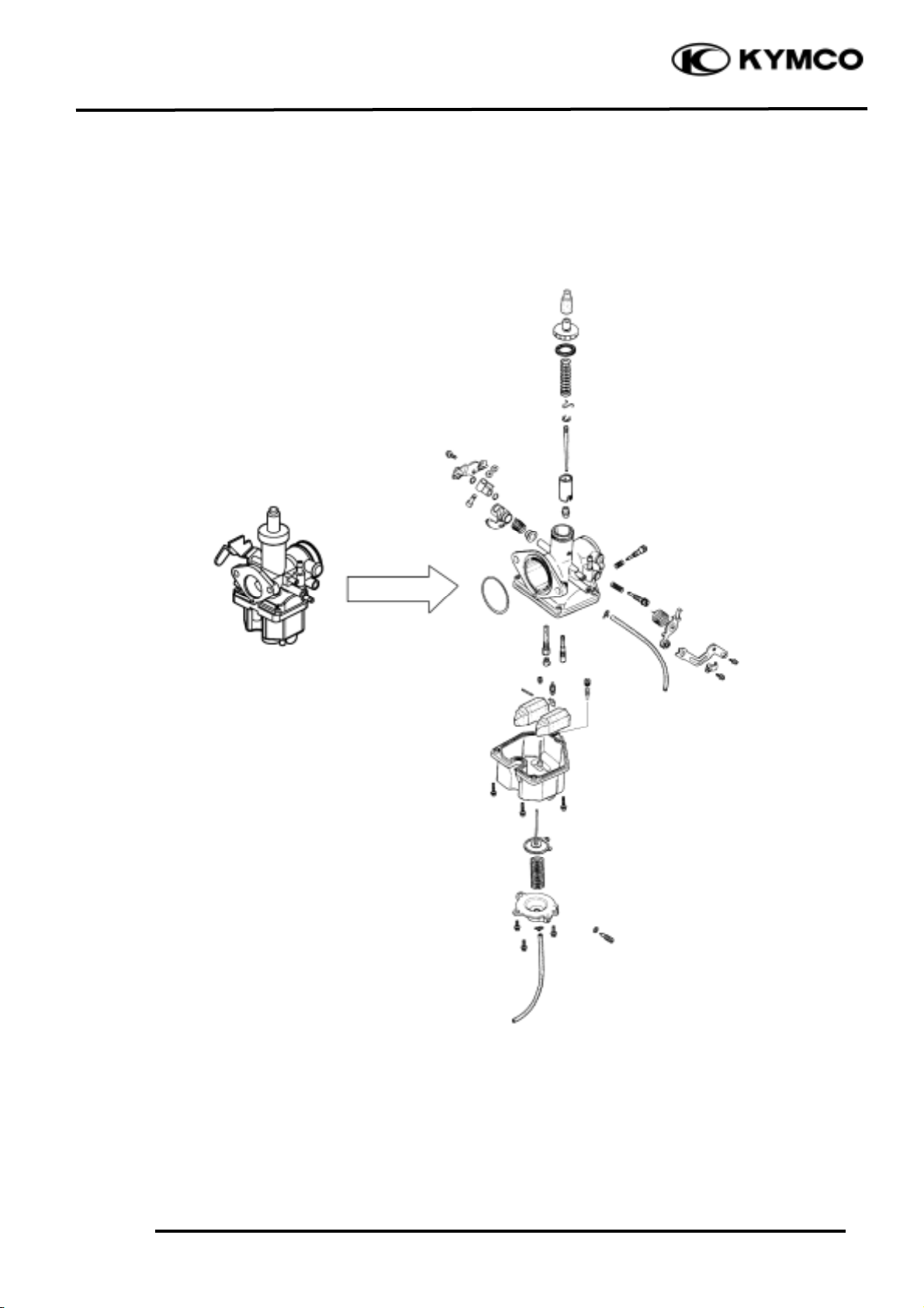
FUEL SYSTEM
__ __ __ _ __ __ __ __ ___ __ __ __ __ _ __ __ __ __ __ _ __ __ __ __ ___ __ __ __ __ _ __ __ __ __ __ _ __ __ __ __ ___ __
SERVICE INFORMATION -------------------------------------------- 5- 2
TROUBLESHOOTING ------------------------------------------------- 5- 3
THROTTLE VALVE DISASSEMBLY/CARBURETOR REMOVAL- 5- 4
FLOAT/FLOAT VALVE/JETS ---------------------------------------- 5- 5
CARBURETOR INSTALLATION ------------------------------------ 5- 8
FUEL TANK------------------------------------------------------------- 5- 9
FUEL VALVE REMOVAL -------------------------------------------- 5- 9
AIR CLEANER ---------------------------------------------------------- 5-10
5
Page 2
5. FUEL SYSTEM
5-1
MX’er SYSTEM
Page 3
5. FUEL SYSTEM
5-2
MX’er SYSTEM
SERVICE INFORMATION
GENERAL INSTRUCTIONS
• Do not bend or twist control cables. Damaged control cables will not operate smoothly.
• When disassembling fuel system parts, note the locations of O-rings. Replace them with new
ones during reassembly.
• Before float chamber disassembly, loosen the drain screw to drain the residual gasoline into a
clean container.
• After the carburetor is removed, plug the intake manifold side with a clean shop towel to prevent
foreign matters from entering.
• When cleaning the carburetor air and fuel jets, the O-rings and diaphragm must be removed first to
avoid damage. Then, clean with compressed air.
• When the motorcycle is not used for over one month, drain the residual gasoline from the float
chamber to avoid erratic idling and clogged slow jet due to deteriorated fuel.
SPECIFICATIONS
MX’er 150
MX’er 125
Item
Standard
Standard
Type
PD
PD
Venturi dia.
f25
f25
Float level
14.8mm
14.8mm
Main jet No.9595
Adjust method
Piston
Piston
Idle speed
1700±100rpm
1700±100rpm
Throttle grip free play
1_ 4mm
1_ 4mm
Air screw opening
2±1/2
2±1/2
Gasoline is very dangerous. When working with gasoline, keep sparks and flames away
from the working area.
Gasoline is extremely flammable and is explosive under certain conditions. Be sure to work
in a well-ventilated area.
Page 4

5. FUEL SYSTEM
5-3
MX’er SYSTEM
SPECIAL TOOL
Float level gauge
TROUBLESHOOTING
Engine cranks but won’t start Engine lacks power
• No fuel in tank • Clogged air cleaner
• No fuel to carburetor • Faulty carburetor
• Cylinder flooded with fuel • Faulty ignition system
• No spark at plug
• Clogged air cleaner Lean mixture
• Intake air leak • Clogged carburetor fuel jets
• Improper throttle operation • Float level too low
• Intake air leak
Engine idles roughly, stalls or runs poorly • Clogged fuel tank cap breather hole
• Excessively used choke • Kinked or restricted fuel line
• Ignition malfunction
• Faulty carburetor Rich mixture
• Poor quality fuel • Float level too high
• Lean or rich mixture • Clogged air jets
• Incorrect idle speed • Clogged air cleaner
Misfiring during acceleration
• Faulty ignition system
• Faulty carburetor
Backfiring at deceleration
• Float level too low
• Incorrectly adjusted carburetor
• Faulty exhaust muffler
Page 5

5. FUEL SYSTEM
5-4
MX’er SYSTEM
THROTTLE VALVE DISASSEMBLY
Remove the front cover.
Remove the front fender.
Remove the carburetor cap.
Pull out the throttle valve.
Disconnect the choke knob cable.
Disconnect the throttle cable and remove the
spring from the throttle valve.
Pry off the needle retainer and remove the jet
needle.
Check the throttle valve and jet needle for
wear or damage.
CARBURETOR REMOVAL
Switch the fuel valve OFF.
Loosen the drain screw to drain the gasoline
from the float chamber.
Disconnect the fuel inlet tube and the choke
cable.
Throttle
Carburetor Cap
Needle Retainer
Spring
Throttle
Jet Needle
Clip
Throttle Cable
Choke Cable
• Keep sparks and flames away from the
work area.
• Drain gasoline into a clean container.
*
Page 6

5. FUEL SYSTEM
5-5
MX’er SYSTEM
Loosen the air cleaner connecting tube band
screw.
Remove the two carburetor lock nuts.
Remove the carburetor
FLOAT/FLOAT VALVE/JETS
FLOAT/FLOAT VALVE DISAS SEMBLY
Remove the float chamber attaching three
screws and remove the float chamber.
Remove the float pin, float and float valve.
FLOAT/FLOAT VALVE INSPECTION
Inspect the float valve seat for wear or
damage.
Inspect the float for damage or fuel level
inside the float chamber.
Float Valve
Screw
Float Pin
Float
Lock Nuts
Screws
Float Valve
Float Valve Seat
Page 7

5. FUEL SYSTEM
5-6
MX’er SYSTEM
JETS/AIR SCREW/THROTTLE STOP
SCREW REMOVAL
Remove the main jet, needle jet holder, and
needle jet.
Remove the slow jet.
Remove the air screw and throttle stop
screw.
CAUTIONS !
FUEL RESERVOIR O-RING CHECK
Remove the O-ring.
INSPECTION
Inspect the check the O-ring for damage.
Replace with new ones if necessary
CARBURETOR CLEANING
Blow compressed air through all passages of
the carburetor body.
• Be careful not to damage the jets and
jet holder when removing them.
• Before removal, turn the throttle stop
screw and air screw in and count the
number of turns until they seat lightly
and then make a note of this.
• Do not force the screw against its seat
to avoid seat damage.
• Be sure to install the O-ring in the
reverse order of removal.
*
Air Screw
Slow Jet
Main Jet
Spring
Washer
O-ring
O-ring
Throttle Stop Screw
Air Screw
Slow Jet
Main Jet
Throttle
Stop Screw
Spring
Page 8

5. FUEL SYSTEM
5-7
MX’er SYSTEM
SLOW/MAIN JET INSTALLATION
Install the slow jet.
Install the needle jet, needle jet holder and
main jet.
Install the throttle stop screw and air screw
Install the float valve, float and float pin.
FLOAT LEVEL INSPECTION
Turn the carburetor upside down so that the
float will go down to make the float valve
contact the float valve seat.
Then slowly tilt the carburetor and measure
the float level with the float level gauge while
the float pin just contacts with float valve.
Float Level:
MX’er 150
14.8mm
MX’er 125
When adjusting, carefully bend the float pin.
Check the float for proper operation and
then install the float chamber.
Float Level Gauge
• When installing the air screw, return it
to the original position as noted during
removal
• After the carburetor is installed, be sure
to perform the Exhaust Emission Test.
*
Float Pin
Slow Jet
Main Jet
Float
Throttle Stop Screw
Air Screw
Page 9

5. FUEL SYSTEM
5-8
MX’er SYSTEM
CARBURETOR INSTALLATION
Install the carburetor onto the intake
manifold and tighten the two lock nuts.
Torque: 0.8_ 1.2kgf-m
Install the air cleaner connecting tube and
tighten the band screw.
THROTTLE VALVE ASSEMBLY
Install the jet needle into the throttle valve
and secure with the needle retainer.
Jet Needle Notch: 4th Notch
(Counted from top to bottom)
Assemble the rubber cover, carburetor cap
and throttle valve spring.
Connect the throttle cable to the throttle
valve.
Install the throttle valve into the carburetor
body.
Connect the accelerating pump cable.
Fully open the throttle and adjust the
accelerating pump cable to align the punch
mark on the accelerating pump arm with the
punch mark on the set plate.
Lock Nut
Groove
Jet Needle
Throttle Stop Screw
Band Screw
Needle Retainer
Clip
Carburetor Cap
Notch
Spring
Throttle
Throttle
Align the groove in the throttle valve
with the throttle stop screw on the
carburetor body.
*
Page 10

5. FUEL SYSTEM
5-9
MX’er SYSTEM
Tighten the choke cable.
FUEL TANK
FUEL TANK REMOVAL
Remove the seat.
Remove the center cover.
Remove the right and left front fender.
Switch the fuel valve “OFF”.
Disconnect the fuel tube and remove two
bolts on the end of the fuel tank.
Remove the fuel tank.
FUEL VALVE REMOVAL
Remove the fuel valve and fuel cup.
Bolts
Fuel Tank
Fuel Valve
Tube
• Keep sparks and flames away from the
work area.
• Wipe off any spilled gasoline.
Warning
Choke Cable
Screw
Side
Page 11

5. FUEL SYSTEM
5-10
MX’er SYSTEM
Remove the screw on the fuel valve control
switch.
Remove the two screws on the fuel valve
body.
INSPECTION
Inspect the fuel valve strainer for dirt and
clog. Clean if necessary.
Replace the O-rings with new ones if they
are damaged or deteriorated.
AIR CLEANER
REMOVAL
Remove the seat.
Remove the four screws on the air cleaner
case cover and the cover.
Remove the air cleaner screen and element.
Fuel Valve Body
Screws
Air Cleaner Case Cover
Control Shaft
Control
Rubber Gasket
Retaining Ring
Washer
 Loading...