

Page 1

18. ONLY ATV ON ROAD AVAILABLE
18-0
MX’er SYSTEM
18
__________________________________________________________________________________
__ __ __ _ __ __ __ __ ___ __ __ __ __ _ __ __ __ __ __ _ __ __ __ __ ___ __ __ __ __ _ __ __ __ __ __ _ __ __ __ __ ___ __
__ __ __ _ __ __ __ __ ___ __ __ __ __ _ __ __ __ __ __ _ __ __ __ __ ___ __ __ __ __ _ __ __ __ __ __ _ __ __ __ __ ___ __
__ __ __ _ __ __ __ __ ___ __ __ __ __ _ __ __ __ __ __ _ __ __ __ __ ___ __ __ __ __ _ __ __ __ __ __ _ __ __ __ __ ___ __
__ __ __ _ __ __ __ __ ___ __ __ __ __ _ __ __ __ __ __ _ __ __ __ __ ___ __ __ __ __ _ __ __ __ __ __ _ __ __ __ __ ___ __
ONLY ATV ON ROAD AVAILABLE
__ __ __ _ __ __ __ __ ___ __ __ __ __ _ __ __ __ __ __ _ __ __ __ __ ___ __ __ __ __ _ __ __ __ __ __ _ __ __ __ __ ___ __
WARING DIAGRAM --------------------------------------------------- 18- 1
BRAKE PEDAL ADJUSTMENT -------------------------------------- 18- 2
INSTRUMENT ---------------------------------------------------------- 18- 3
INDICATOR LIGHT---------------------------------------------------- 18- 3
HAZARD SWITCH ----------------------------------------------------- 18- 4
HORN--------------------------------------------------------------------- 18- 4
18
Page 2
18. ONLY ATV ON ROAD AVAILABLE
18-1
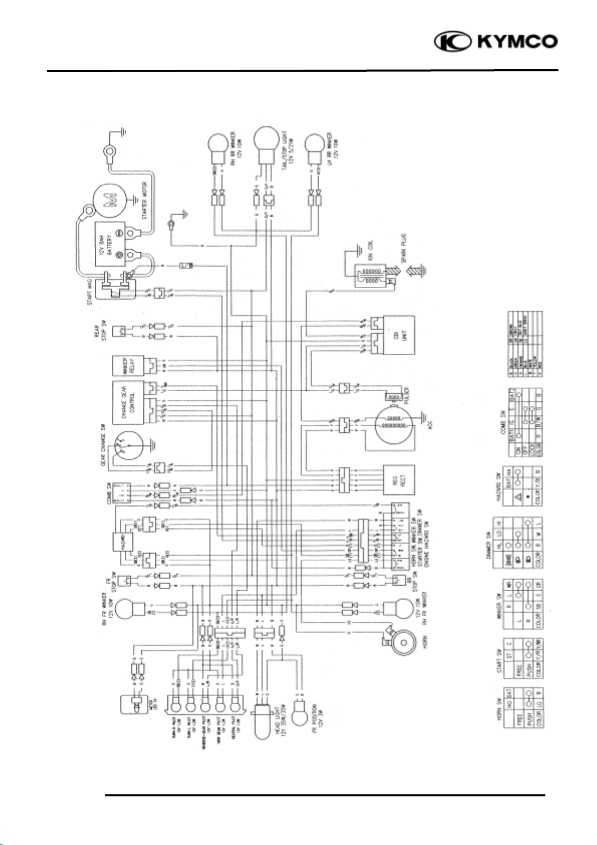
MX’er SYSTEM
WIRING DIAGRAM
Page 3

18. ONLY ATV ON ROAD AVAILABLE
18-2
MX’er SYSTEM
BRAKE PEDAL ADJUSTMENT
The brake pedal free play should be
adjusted
to 10~20 mm (0.4~0.8 in) at the brake pedal
pivot. If the free play is incorrect, adjust as
Follows:
Keep front brake lever free play at 10~20
mm (0.4~0.8 in). (Refer to page 3-9)
Loosen the lock nut.
Turn the adjusting bolt until the front
lower brake cable is tensed.
Apply the front brake lever and check front
bake cam lever to make sure that the brake
does not drag after adjusting.
Tighten the lock nut.
Turn the adjusting nut on the brake cam
lever to decrease play or increase play.
Turn the adjusting nut until specified free
Play is obtained.
Brake Pedal
10~20mm
Front lower brake cable
Lock Nut
Brake Cam Lever
Adjusting Bolt
Adjusting Nut
Page 4

18. ONLY ATV ON ROAD AVAILABLE
18-3
MX’er SYSTEM
INSTRUMENT
REMOVAL
Remove the two instrument attaching
screws.
Disconnect the instrument.
Remove battery cover on instrument back to
replace battery.
SENSOR WHEEL
If the sensor is lost or wore, the speed will
be not calculated on the instrument.
INDICATOR LIGHT
REMOVAL
Remove the screw and disconnect the cover
of the ignition switch.
Screws
Battery Cover
After replace battery, the instrument
will be reset. (Refer to owner’s manual)
*
Speed Wheel
Screw
Page 5

18. ONLY ATV ON ROAD AVAILABLE
18-4
MX’er SYSTEM
Remove the bulb socket and bulb.
Check the bulb for damage and replace with
a new one if necessary.
INSTALLATION
The installation sequence is the reverse of
removal.
HAZARD SWITCH
Check for continuity between the wires
indicated below.
Color
Position
Yellow/
Black
Black
○
○
●
HORN
REMOVAL
Disconnect the horn switch wire.
Remove the bolt and remove horn.
INSTALLATION
The installation sequence is the reverse of
removal.
Bulb Socket
Bulb
Hazard Switch
Horn Switch wire
Bolt
 Loading...