

Page 1

© Young Chang Co., Ltd. 2002. All rights reserved. Kurzweil ® is a product line of
Young Chang Co., Ltd. Young Chang®, Kurzweil ®, V. A. S. T. ®, KDFX®,
Pitcher®, and LaserVerb®, RSP8 ™, HUB7 ™, KSP8 ™, K2600™, K2500™, and
K2000™ are trademarks of Young Chang Co., Ltd. SmartMedia™ is a trademark
of Toshiba Corporation. ADAT® is a registered trademark of Alesis Corporation.
All other products and brand names are trademarks or registered trademarks of
their respective companies. Product features and specifications are subject to
change without notice.
Part Number: 910366 Rev. A
Page 2

Young Chang International Contacts
Contact the nearest Young Chang office listed below to locate
your local Young Chang/ Kurzweil representative.
Young Chang America, Inc.
P.O. Box 99995
Lakewood, WA 98499-0995
Tel: 1-253-589-3200
Fax: 1-253-984-0245
Young Chang Co., Ltd.
178-55 Gajwa-Dong
Seo-Ku, Inchon, Korea 404-714
Tel: 011-82-32-570-1380
Fax: 011-82-32-570-1218
Young Chang America, Inc. (Canadian Division)
3650 Victoria Park Ave. Suite 105
Toronto, Ontario Canada M2H 3P7
Tel: 1-416-492-9899
Fax: 1-416-492-9299
World Wide Web Home Page
http://www.kurzweilmusicsystems.com
Page 3

IMPORTANT SAFETY & INSTALLATION INSTRUCTIONS
INSTRUCTIONS PERTAINING TO THE RISK OF FIRE,
ELECTRIC SHOCK, OR INJURY TO PERSONS
WARNING
followed, including the following:
1) Read these instructions.
2) Keep these instructions.
3) Heed all warnings.
4) Follow all instructions.
5) Do not use this apparatus near water.
6) Clean only with a dry cloth.
7) Do not block any of the ventilation openings. Install in accordance
8) Do not install near any heat sources such as radiators, heat regis-
9) Do not defeat the safety purpose of the polarized or grounding-type
10) Protect the power cord from being walked on or pinched, particularly
11) Only use attachments/accessories specified by the manufacturer.
12) Use only with a cart, stand, tripod, bracket, or table specified by the
13) Unplug this apparatus during lightning storms or when unused for
14) Refer all servicing to qualified service personnel. Servicing is re-
15) Do not expose this apparatus to dripping or splashing and ensure
16) WARNING: To reduce the risk of fire or electric shock do not expose
- When using electric products, basic precautions should always be
with the manufacturer’s instructions.
ters, stoves, or other apparatus (including amplifiers) that produce
heat.
plug. A polarized plug has two blades with one wider than the other.
A grounding type plug has two blades and a third grounding prong.
The wide blade or the third prong are provided for your safety. When
the provided plug does not fit into your outlet, consult an electrician
for replacement of the obsolete outlet.
at plugs, convenience receptacles, and the point where they exit
from the apparatus.
manufacturer, or sold with apparatus. When a cart is used, use caution when moving the cart/apparatus combination to avoid injury
from tip-over.
long periods of time.
quired when the apparatus has been damaged in any way, such as
power-supply cord or plug is damaged, liquid has been spilled or objects have fallen into the apparatus, the apparatus has been exposed to rain or moisture, does not operate normally, or has been
dropped.
that no objects filled with liquids, such as vases, are placed on the
apparatus.
this apparatus to rain or moisture.
SAVE THESE INSTRUCTIONS
Page 4
RADIO AND TELEVISION INTERFERENCE
ying
Warning:
Young Chang could void your authority to operate the instrument.
Important:
use only high quality shielded cables.
Note:
Class A digital device, pursuant to Part 15 of the FCC Rules. These limits are
designed to provide reasonable protection against harmful interference in a
residential installation. This instrument generates, uses, and can radiate radio
frequency energy and, if not installed and used in accordance with the
instructions, may cause harmful interference to radio communications. However,
there is no guarantee that interference will not occur in a particular installation. If
this instrument does cause harmful interference to radio or television reception,
which can be determined by turning the instrument off and on, the user is
encouraged to try to correct the interference by one or more of the following
measures:
• Reorient or relocate the receiving antenna.
• Increase the separation between the instrument and the receiver.
• Connect the instrument into an outlet on a circuit other than the one to which the
receiver is connected.
• If necessary consult your dealer or an experienced radio/television technician for
additional suggestions.
NOTICE
This apparatus does not exceed the Class A limits for radio noise emissions from
digital apparatus set out in the Radio Interference Regulations of the Canadian
Department of Communications.
AVIS
Le present appareil numerique n’emet pas de bruits radioelectriques depassant
les limites applicables aux appareils numeriques de la class A prescrites dans le
Reglement sur le brouillage radioelectrique edicte par le ministere des
Communications du Canada.
Changes or modifications to this instrument not expressly approved by
When connecting this product to accessories and/or other equipment
This instrument has been tested and found to comply with the limits for a
CAUTION
RISK OF ELECTRIC SHOCK
DO NOT OPEN
CAUTION: TO REDUCE THE RISK OF ELECTRIC SHOCK,
DO NOT REMOVE THE COVER
NO USER SERVICEABLE PARTS INSIDE
REFER SERVICING TO QUALIFIED SERVICE PERSONNEL
The lightning flash with the arrowhead symbol,
within an equilateral triangle, is intended to alert
the user to the presence of uninsulated
"dangerous voltage" within the product's
enclosure that may be of sufficient magnitude
to constitute a risk of electric shock to persons.
The exclamation point within an equilateral
triangle is intended to alert the user to the
presence of important operating and
maintenance (servicing) instructions in the
literature accompan
the product.
Page 5

Table of Contents
Using the RSP8 . . . . . . . . . . . . . . . . . . . . . . . . . . . . 1-1
HUB7 . . . . . . . . . . . . . . . . . . . . . . . . . . . . . . . . . 1-1
KSP8 Software . . . . . . . . . . . . . . . . . . . . . . . . . . . . . 1-2
Setting Up Your RSP8 . . . . . . . . . . . . . . . . . . . . . . . 1-3
Connecting Your RSP8. . . . . . . . . . . . . . . . . . . . . . . 1-4
Aftermarket Cables . . . . . . . . . . . . . . . . . . . . . . . 1-5
Starting Up Your RSP8. . . . . . . . . . . . . . . . . . . . . . . 1-6
Adjusting the RSP8 Display . . . . . . . . . . . . . . . . 1-6
Remote Configuration Menus. . . . . . . . . . . . . . . . . . 1-7
Using the Joystick. . . . . . . . . . . . . . . . . . . . . . . . . . . 1-9
The Remote:JOYSTIK Page. . . . . . . . . . . . . . . . 1-10
What the Joystick Transmits. . . . . . . . . . . . . . . . 1-12
Joystick Modes . . . . . . . . . . . . . . . . . . . . . . . . . . 1-14
Using MIDI to Record Panning Information . . . 1-16
Using MIDI for Effect Modulations . . . . . . . . . . 1-20
Using the Control Knobs . . . . . . . . . . . . . . . . . . . . . 1-23
The Remote:KNOBS Page . . . . . . . . . . . . . . . . . 1-23
Intuitive Entry with Control Knobs or Joystick . 1-28
Using the HUB7. . . . . . . . . . . . . . . . . . . . . . . . . . . . 2-1
Which KSP8 Are You Talking To? . . . . . . . . . . 2-2
Configuration Examples . . . . . . . . . . . . . . . . . . . . . . 2-3
HUB7 Connecting Cables. . . . . . . . . . . . . . . . . . . . . 2-6
HUB7 Power Adapter . . . . . . . . . . . . . . . . . . . . . . . . 2-7
RSP8 Diagnostics and Troubleshooting . . . . . . . . A-1
RSP8 Diagnostics . . . . . . . . . . . . . . . . . . . . . . . . A-1
Main Diagnostic Menu . . . . . . . . . . . . . . . . . . . . A-2
Burnin Diagnostic . . . . . . . . . . . . . . . . . . . . . . . . A-2
Description of the Individual Diagnostic Tests . A-3
Description of the Controls Diagnostic. . . . . . . . A-6
In Case of Problems . . . . . . . . . . . . . . . . . . . . . . . . . A-9
v
Page 6

vi
Page 7

Chapter 1
Using the RSP8
The RSP8 is a remote control for Kurzweil’s KSP8 multi-bus
signal processor that provides you convenient access to all of the
KSP8’s front panel functions. The RSP8 also gives you eight
knobs for adjusting effect and other parameters, along with a
joystick for surround panning. You can also configure the knobs
and/or joystick to send MIDI controller values, to either a KSP8
or an external device.
HUB7
Chapter 2 of this manual describes the HUB7 repeater/
concentrator, which lets you use a single RSP8 to control up to
seven KSP8s, and also allows you to extend cable distances
between the RSP8 and KSP8(s).
1-1
Page 8

Using the RSP8
KSP8 Software
To make use of the RSP8, you need operating system software
version 1.5 or higher running on your KSP8. If the version level of
your KSP8 software (as shown on the KSP8 startup screen) is
lower than 1.5, and you have not been provided with a software
update, contact your Kurzweil dealer, or check for the latest
updates by logging on to our web site:
http://www.kurzweilmusicsystems.com
For Other KSP8 Questions
This manual describes only KSP8 features that pertain to the
RSP8 and HUB7. For information on all other KSP8 functions,
refer to the
KSP8 User’s Guide
.
1-2
Page 9
Setting Up Your RSP8
Setting Up Your RSP8
The RSP8 lets you access up to seven KSP8s from any location
that’s convenient for you. You can either:
•
set the RSP8 on top of a table or mixing desk (the bottom of
the RSP8 is covered with a soft material that will not scratch
surfaces).
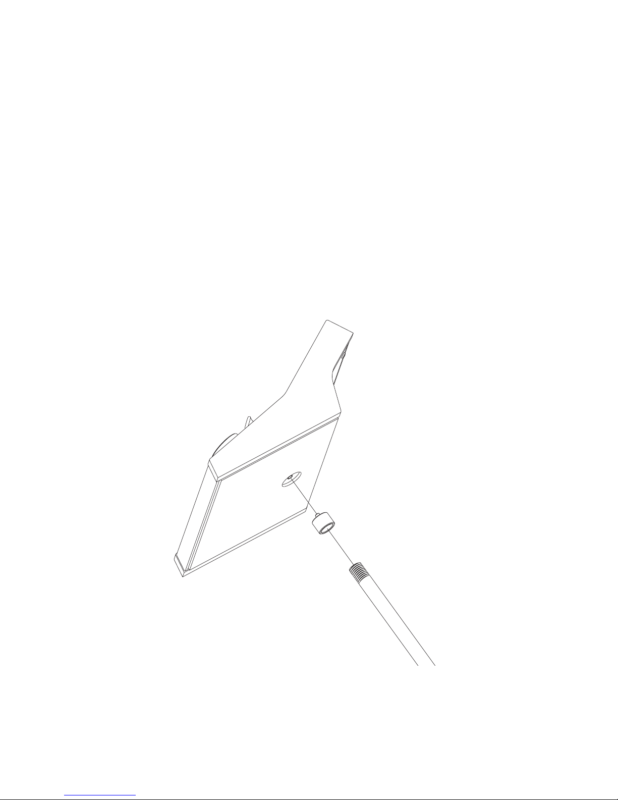
•
attach the supplied microphone stand adapter to the bottom
of the RSP8, then thread the adapter onto the top of a
standard microphone stand, as shown in Figure 1-1. You’ll
probably find this works best if you attach the adapter to the
bottom of the RSP8 before you attach it to the mic stand.
Figure 1-1. Attaching the RSP8 to a microphone stand.
1-3
Page 10

Using the RSP8
Connecting Your RSP8
Your RSP8 is supplied with a fully-shielded 16 meter (52 foot)
connecting cable. Plug one end of this cable into the Remote
connector on the back of your KSP8, then plug the other end into
the rear of your RSP8. Note that the flat side or arrow marking on
the connector should face up on the RSP8 and down on the KSP8.
The RSP8 is also powered through this cable so there is no
separate power cord or adapter to worry about.
The KSP8 and RSP8 allow “hot plugging,” which means that you
can connect and disconnect the cable at any time, whether or not
the power is on.
There is no power switch on the RSP8; it simply follows the
power status of the connected KSP8. If you want your RSP8 to be
fully off, simply unplug it. You may find it more convenient to
use the standby feature (described in the
which reduces power consumption, extends display life, and
allows for near-instant waking.
KSP8 User’s Guide
),
1-4
Page 11

Connecting Your RSP8
Aftermarket Cables
If the original cable becomes damaged or you would like to use a
different length cable, you can buy replacements from sources
listed on the www.kurzweilmusicsystems.com web site.
The required cable characteristics are:
A. MiniDin-8 male plug at each end
B. All 8 pins wired
C. “Straight through” or “one-to-one” wiring, NOT “cross-
over” wiring
D. Overall braid and foil shield, wired to the plug's shell at
each end
E. #24 gauge wires for length up to 16 meters (52 feet)
#26 gauge wires for length up to 10 meters (33 feet)
#28 gauge wires for length up to 6.5 meters (21 feet)
F. The 8 wires must be arranged as 4 twisted pairs paired as
follows:
Pins 1 and 8 or pins 1 and 2
Pins 2 and 7 or pins 7 and 8
Pins 3 and 4
Pins 5 and 6
Note: Apple Macintosh “serial cables” will NOT work because they
violate requirement C above (they are “crossover wired”).
The wire gauge and length limits listed above are very important
to ensure that adequate power is delivered to your RSP8. If in
doubt, refer to the Diagnostics section of this manual for a
voltage test you can run. To go longer than 16 meters – up to 300
meters – you will need to use a HUB7; see the HUB7 section for
details.
1-5
Page 12

Using the RSP8
Starting Up Your RSP8
When you first start up your RSP8, either by plugging in the
connecting cable or by powering up the KSP8 to which it is
attached, there will first be a short pause, after which all LEDs
turn on for 1 second then turn off.
The display backlight then turns on gradually until it stabilizes;
self diagnostics run, and the joystick calibration is read from nonvolatile memory. After the RSP8 startup screen displays,
notification that an RSP8 is connected is sent to the KSP8, and the
KSP8 and RSP8 synchronize their displays.
At this point you can control the KSP8 from either its front panel
or from the RSP8.
If the self diagnostics fail, you will be asked whether to continue
or recalibrate the joystick. See Appendix A of this manual for
details on how to proceed.
Adjusting the RSP8 Display
You can adjust the display contrast using the thumb knob to the
left of the display. Adjust for the most pleasing contrast when
viewing from your normal work position. It is normal for the
setting to change slightly as your work surface and RSP8 warm
up, so you may need to readjust the display after an hour or so.
By default the overall display and LED brightness will be at their
maximum, which is suitable for a brightly lit institutional area.
For a dimly lit studio you may desire to reduce the brightness.
Enter Master mode by pressing the MASTER soft button (the
button on the front panel that is just below the word MASTER on
the RSP8’s display), then press the UTIL soft button followed by
the REMOTE soft button. Scroll down to the fourth item,
Backlight, using the down cursor button. You can change the
value using the Alphanumeric Pad or the Alpha Wheel to any
value from 1 (minimum) to 127 (maximum). The brightness of the
LEDs will also change to match the display, although they will
not turn off completely.
1-6
Page 13

Remote Configuration Menus
Remote Configuration Menus
Most RSP8 features work automatically when you connect it to a
KSP8. Some of the specialized functions, however, may require
some configuration before you can use them.
To access the Remote Configuration Menus (either from the front
panel of the KSP8, or from the RSP8 itself), press the
soft button, then
double press the rightmost two soft buttons beneath your KSP8
or RSP8’s display for a shortcut to this page.
Remote:SETUP||||||||||||||||||||||||||||
||||||||||||||||||||||||||||
Knob|Mode||:Auto|||||||||||||||||||||
Joy|Mode|||:Auto||||||||||||||||||
3-way|Mode|:All|axis|||||||||||||||||||||
Backlight||:127|||||||||||||||||||||||
MIDI|Xmit||:Local|||||||||||||||||||||||
SELECT|SETUP||KNOBS||JOYSTIK|||||||Done|
UTIL
followed by
REMOTE
. Or, you can
MASTER
Soft Buttons on the Remote Configuration Menus
You’ll use
the RSP8 through a HUB7. This soft button lets you choose the
current KSP8 for RSP8 control.
SETUP, KNOBS
the same names. They’re discussed in detail a little further on.
Press
Configuration Menus.
Done
SELECT
when you are ready to leave the Remote
when you have several KSP8s connected to
, and
JOYSTIK
take you to the Remote pages of
1-7
Page 14

Using the RSP8
Menu Items on the Remote:SETUP Page
The Remote:SETUP page includes the following:
•
Knob Mode
Specifies whether the eight control knobs on the RSP8 control
the values of Quick and EQ/Sends parameters (Quick), send
MIDI data (MIDI), or do either (Auto) depending on the
currently displayed page. Auto is the default. Although this
item appears on the Remote:SETUP and Remote:KNOBS
pages, it cannot be set separately for individual knob banks.
When you change the setting of Knob Mode on any of the
pages where it is displayed, the setting is changed globally.
•
Joy Mode
Specifies whether the RSP8’s joystick sends panning
information (Pan), MIDI data (MIDI), or either (Auto)
depending on the currently displayed page. Auto is the
default. Although this item appears on the Remote:SETUP
and Remote:JOYSTIK pages, it cannot be set separately for
individual joystick banks. When you change the setting of
Joy Mode on any of the pages where it is displayed, the
setting is changed globally.
– Quick, MIDI, Auto
– Pan, MIDI, Auto
•
3-way Mode
– Front-back, All axis
Sets the way that the joystick works when you use the “FX1-6
3-Way” mono-to-5.1 panner on the FXSEND page.
back
keeps the front-back axis fixed, while
All axis
Front-
allows
you to move the front back axis as well as the sound source
position.
•
Backlight
– 1-127
Controls the RSP8 display intensity. See “Adjusting the RSP8
Display” on page 1-6.
•
MIDI Xmit
– Local, MIDI, Both
You can send MIDI data from the RSP8 only to the attached
KSP8 (Local), to the KSP8’s MIDI Out port (MIDI), or Both.
1-8
Page 15

Using the Joystick
Using the Joystick
The RSP8’s joystick is a positioning control that gives you
maximum flexibility when panning or sending MIDI controller
values.
The most convenient place to start using the joystick is the
Remote:JOYSTIK page, and the quickest way to get to this page is
to press and hold the
Remote:JOYSTIK page will appear, as shown below:
Remote:JOYSTIK||||||||||||||||||||||||||
Bank||:1||||||||||||||||||||||||||||||||
Mode||:Auto
Axis|||X|||Y|||Rad|Angle|
Chan||:Cur|Cur|Cur|Cur||||
Ctrl||:25||26||27||28|||||
Value||0|||0|||0|||0||||||||||||||||||||
SELECT|SETUP||KNOBS||JOYSTIK|||||||Done|
joystick
button on the RSP8. The
joystick display
By default, the joystick is off. To enable it, press the joystick
button to the left of the joystick, and the LED within that button
will light. The dot on the joystick display (at the far right of the
screen) will jump to show the current position of the joystick. To
disable the joystick, press the button again, and the LED will go
out. Needless to say, the light must be on for the joystick to
function.
1-9
Page 16

Using the RSP8
The Remote:JOYSTIK Page
The parameters for the joystick are all displayed on the Remote:
JOYSTIK page. You can reach this page by either pressing the
JOYSTIK soft button on any Remote Configuration Menu, or by
pressing and holding the joystick button on the RSP8. Note that
being on this page doesn’t make the joystick active; you still have
to press the joystick button on the RSP8 to do that.
Remote:JOYSTIK||||||||||||||||||||||||||
Bank||:1||||||||||||||||||||||||||||||||
Mode||:Auto
Axis|||X|||Y|||Rad|Angle|
Chan||:Cur|Cur|Cur|Cur||||
Ctrl||:25||26||27||28|||||
Value||0|||0|||0|||0||||||||||||||||||||
SELECT|SETUP||KNOBS||JOYSTIK|||||||Done|
• Bank - 1–8
For your convenience, you can configure and store up to
eight banks of joystick settings. These are separate from the
eight knob banks that you can also create.
• Mode - Auto, MIDI, or Pan
Specifies whether the RSP8’s joystick sends panning
information, MIDI data, or either (Auto) depending on the
currently displayed page. Auto is the default.
Although this item appears on the Remote:SETUP and
Remote:JOYSTIK pages, it cannot be set separately for
individual joystick banks. When you change the setting of
Joy Mode on any of the pages where it is displayed, the
setting is changed globally.
• Axis - X, Y, Rad, Angle (display field only)
These are the labels for the four columns showing the values
that the joystick sends: X and Y axis position values, as well
as the numeric values for Radius and Angle. Generally a
panner will use two of these axes together: X and Y, or Radius
and Angle, depending on the panner. All four are available at
all times, however, so you can use any or all of them as
controllers when you use the joystick to send MIDI.
1-10
Page 17

Using the Joystick
• Chan - Off, 1–16, Cur, Stu
For MIDI or Auto mode, sets the MIDI channel for MIDI data
sent from this axis. “Cur” means that the channel used by the
current FXBus will automatically be selected. “Stu” tracks the
studio channel (as set on the Master page).
• Ctrl - 0–127
(MIDI or Auto mode): specifies MIDI controller for this axis.
The default MIDI controllers sent by the joystick are:
X: 25 Rad: 27
Y: 26 Angle: 28
• Value - 1–127 (display field only)
Displays the current numeric value of X, Y, Rad, or Angle,
based on the joystick position.
1-11
Page 18

Using the RSP8
What the Joystick Transmits
The RSP8’s joystick can transmit 4 values: X, Y, Rad and Angle.
You can configure these values to:
• control surround sound panners on the KSP8’s FXSEND
pages
• send MIDI controller values to KSP8 parameters
• send MIDI to external gear.
The chart below summarizes the MIDI and pan values you can
send with the joystick. Note that zero is always where the handle
is pointing upwards (the 12 o’clock position).
Pan angle: 360˚/0˚
Angle value: 127/0
Y axis (0–127)
Pan angle: 270˚
Angle value: 96
X axis (0–127)
(LRPan: -100%–100%)
Pan angle: 180˚
Angle value: 64
(FSPan: 0%–100%)
R
Theta (Angle)
adius (0–127, 0–100%)
Pan angle: 90˚
Angle value: 32
Figure 1-2. MIDI and pan values sent by the RSP8 joystick.
X and Y perform exactly as you might expect, describing the
vertical and horizontal position of the joystick handle. X is left-toright movement of the handle, with the far left being the
minimum numeric value, and the far right being the maximum. Y
1-12
Page 19

Using the Joystick
is the bottom-to-top position. In other words, X and Y basically
describe a point within a square. Because the joystick has a
circular base, however, the combinations of X and Y that are “in
the corners” are not generally available.
The other 2 parameters, Rad and Angle, also describe the position
of the joystick handle, but using polar geometry: the location of
the point in the circle is expressed as a distance from the center
and an angle.
Rad is short for radius, which indicates the distance of the handle
from the center of the circle. When the joystick is centered in its
ring, the radius is 0. As you move the joystick in any direction,
the value increases, until it reaches the outer ring, where Rad will
be at a maximum (127).
Angle, sometimes called theta, tells the angle of the handle. As
you move the joystick clockwise, the value of angle will increase;
when you move the joystick counterclockwise, the angle will
decrease. The value is greatest just before the 12 o’clock position,
where it jumps abruptly down to 0. When the Angle controller is
connected to the Angle parameter in a panner, there does not
appear to be an abrupt change, because of the circular behavior of
the panner (i.e., 0 degrees is the same as 360 degrees). The panner
wraps smoothly back around to center, even though the Angle
controller value jumps from 127 to 0.
You can play with the joystick while on the Remote:JOYSTIK
page to get a sense of how each value changes when you move
the handle. Following the outer ring with the handle allows you
careful control of the angle parameter, while the radius will be at
maximum. If you center the joystick in the ring, you can reduce
the radius to nearly zero, but controlling the angle parameter will
be more difficult.
The numeric value generated by the joystick will be the same
whether you are using the joystick for panning or MIDI. The
parameters that are being controlled inside the KSP8, however,
and how they are interpreted, will depend on the mode you have
selected. The following sections describe the three joystick
modes: Pan, MIDI, and Auto.
1-13
Page 20

Using the RSP8
Joystick Modes
You can set the joystick to be in Auto, MIDI, or Pan mode.
Auto Mode
Auto is the default joystick mode, and means that the joystick
automatically performs panning and/or MIDI capabilities,
depending on the currently displayed screen. When the currently
displayed page is a Studio:FXSEND page for a 5.1 panner, for
example, the joystick will perform panning.
Pan Mode
In Pan (or Auto) mode, you can use the joystick to perform
surround sound panning. Depending on the 5.1 panner you
select, the KSP8 will use either the X and Y or the Radius and
Angle values sent by the joystick to position the sound source.
First make sure that the current studio is set up to use one of the
5.1 panners. Press the EQ/Sends button, then check the FXSEND
page for the current studio to see a joystick display just like the
one on the Remote:JOYSTIK page. If the joystick display does not
appear on the right side of the FXSEND page, double check to see
if you’ve selected one of the 5.1 panners (FX1-6 X-Y, FX1-6 RTheta, or FX1-6 3-Way). Keep in mind, too, that the choice of
panners available to you on the FXSEND page will depend on the
input grouping you have selected on the Studio:INGRP page.
See the KSP8 User’s Guide if you need more information about
setting up a 5.1 studio.
1-14
Page 21

Using the Joystick
When performing surround panning, what you see on the
joystick display will depend on the type of panner you have
selected:
On a mono-to-5.1 panner, the positioning dot moves with the
handle and represents the sound location. With the 3-Way
panners, three dots appear on the joystick display; these
represent front (top), back (bottom), and sound position. Use the
3-Way Mode parameter on the Remote:SETUP page to specify
whether or not you want the front and back positions to move as
you pan.
For a stereo-to-5.1 panner, two dots are shown. The joystick
points at the center of the image, and unless the width is set to 0,
the center of the image is a point between the two dots.
With 5.1-to-5.1 panners, there are five dots representing the
surround image. The joystick points at the center of the image,
which is the location of the center channel.
The following controllers match the way that the three types of
5.1 panners act when controlled directly:
X-Y Panner:
Joystick X axis = LRPan
Joystick Y axis = FSPan
R-Theta panner:
Joystick Rad value = Rad
Joystick Angle (Theta) value = Angle
3-Way panner:
When 3-Way mode is Front-Back, only FSPan is changed by the joystick.
Joystick X axis = LRPan
Joystick X axis = SurLR
Joystick Y axis = FSPan
1-15
Page 22

Using the RSP8
MIDI Mode
When you use the joystick to send MIDI controller data, you will
need to route that data to the desired parameters. Do this using
Studio and Chain MODs, as described in the KSP8 User’s Guide.
MODs let you route the joystick (or any MIDI controller) to any
parameter in the unit. Each axis can send on a different MIDI
channel. Furthermore, you can assign each axis to multiple
parameters on the same channel.
If you're unsure whether the joystick is sending MIDI, check the
MIDI LED. If it lights when you move the joystick, then you’re
sending MIDI; the destination of the MIDI messages will depend
on the setting of the MIDI Xmit parameter on the Remote:SETUP
page. MIDI messages will also show up in the MIDIscope utility,
which you can reach quickly by double pressing the middle two
soft buttons (labeled utility) then pressing the MIDI soft button.
See the KSP8 User’s Guide for more information about MIDIscope.
Using MIDI to Record Panning Information
Use MIDI to automate panning by recording joystick moves from
the RSP8 and KSP8 to an external sequencer. You can
subsequently play back the prerecorded pan moves from the
sequencer to the KSP8.
Because there are up to 8 input/EQ buses in a Studio, when you
wish to control one of them explicitly, it is necessary to “set up a
MOD” in the studio to patch the desired control in to the desired
parameter. Once you have set up your modulators to use a MIDI
controller such as the joystick, you can use an external MIDI
sequencer to record and play back panning movements. Here's
how:
Go to the Remote:SETUP page by pressing the rightmost two soft
buttons together. Set Joy Mode to MIDI, and set MIDI Xmit to
Both. This enables transmission of exclusively MIDI data from
the joystick to both the local KSP8 and the MIDI Out port on the
KSP8. Now press the JOYSTIK soft button.
1-16
Page 23

Using the Joystick
Assuming you have not yet customized the joystick settings, you
will see the screen shown on page 1-10. Switch the bank
parameter to 2, and you will see that all four Channel values
change from Cur (current FXBus channel) to Stu (Studio
channel). Since the Studio MIDI channel defaults to 9, you will be
transmitting the MIDI data on channel 9. (The Studio channel
may be changed on the Master page.)
For the first example, we will automate a stereo panner, so we
will only need a single MIDI controller, presumably the joystick's
X-axis, so side-to-side motion of the joystick will pan the signal
side-to-side. Note that the X-axis Ctrl value is set to 25, meaning
MIDI CC#25. You may wish to disable transmission of the Y, Rad,
and Angle controllers by setting the Chan parameter for each
column to Off. Alternately, you can leave them on, but you will
record excess data into your sequencer and will probably want to
remove it later. Now press Done to exit the Remote menu.
Next, select Studio 1, 4SterIn>4SterFX. To see what is selected as a
panner for input buses 1-2, press EQ/sends, then FXSEND, then
the 1-2 button. You should see the output of EQ1-2 being sent to
FXbuses 1-2 using the “FX1-2 Bal” block. Press the EQ/sends
button to go back to the main Studio view.
Next, press the rightmost button, labelled more> to go to the S
MOD pages.
Press S MOD1. Across one line on the screen, set the Bus column
to In1-2, the Param column to Send1Bal, the Adjust value to
-100% (hard left), the Source to MIDI25, and the Depth to 200%
(-100% + 200% = 100%, or hard right). The screen should look like
this:
Studio:S|MOD1||||||||||||||||||||||||||
Bus:||Param:|||Adjust:|Source:|||Depth:
In1-2|Send1Bal|-100%|||MIDI25||||200%
None||None|||||||||||||Off
None||None|||||||||||||Off
None||None|||||||||||||Off
None||None|||||||||||||Off|||||||||||||
<more|S|MOD1|S|MOD2|S|MOD3|S|MOD4|more>
1-17
Page 24

Using the RSP8
Now press the store button and save the studio by either pressing
the store button again (to save wherever the dialogue suggests)
or by selecting a new ID# then pressing store again.
Make sure the joystick is enabled by pressing it once. The LED
should come on to indicate that it is on. Play some audio into
your KSP8's 1-2 analog inputs. Move the joystick side-to-side to
hear your input signal pan accordingly. If it does not appear to
work, verify the above steps. Make sure that you are sending on
the correct channel (the studio channel or “Stu”) on the
Remote:JOYSTIK page, and verify that the Joy Mode is MIDI and
MIDI Xmit on the Remote:SETUP page is set to Both. (Local will
work audibly but will not be transmitted to the MIDI Out port, so
you won't see the MIDI data in your sequencer.) Also verify that
the studio MOD is set up correctly, as shown above, that the
controller sent on the JOYSTIK page matches that set on the S
MOD page, and verify that the joystick LED is on. If you are
using a digital input, say, the base AES pair, you won't be hearing
any audio at all, so press the config button and set In 1 and In 2 to
AES/EBU 1L and AES/EBU 1R, respectively.
Now that your mod is set up and working, press record on your
sequencer and record some pan movements. You should end up
recording a stream of MIDI25 controller messages on MIDI
channel 9. When you play back the sequence, the KSP8 will
“hear” those messages on its studio channel, and will respond in
real-time because of the S MOD you set up.
To record another pan movement in the same studio, but on
another bus, simply change the joystick X-axis controller on the
Remote:JOYSTIK page to send a different MIDI CC#, and use
that as the source for your second Studio mod.
To record pan movements for a surround panner, follow the same
basic steps, with the following differences:
1. Select Studio#9 6 MonoIn>5.1 FX+ instead of Studio#1. Set up
your incoming signal so that it is a mono signal coming in on
Input 1. You can do this from your mixer, or on the INSEL page
by turning off anything other than In 1. Like before, make sure
1-18
Page 25

Using the Joystick
that if you are using a digital input, you select the proper source,
such as AES/EBU 1L for Input 1. Select the panner you want to
use on the FXSEND page (FX1-6 X-Y, FX1-6 R-Theta, or FX1-6 3Way).
2. You will need two controllers, either X and Y (for the X-Y
panner), or Rad and Angle (for the R-Theta panner). As in the
previous example, you may want to disable the controllers you
are not using on the Remote:JOYSTIK page. (You may only need
the Y-axis control for controlling the 3-Way panner as it was
intended to work, with a fixed front and rear position and a
single front-to-back controller for the FSPan parameter, to move a
signal along a path from the front position (LRPan) to the back
position (SurLR).)
Your S MODs will look like this:
For the X-Y Panner:
Bus:|Param:|||||Adjust:||Source:||Depth:
In1||Send|LRPan|-100%||||MIDI25||||200%
In1||Send|FSPan||100%||||MIDI26|||-100%
For the R-Theta panner:
Bus:|Param:|||||Adjust:||Source:||Depth:
In1||Send|Rad|||0%|||||||MIDI27|||100%
In1||Send|Angle|0.0deg|||MIDI28|||360.0d
For the 3-Way Panner (suggested):
Bus:|Param:||||||Adjust:|Source:||Depth:
In1||Send|FSPan||100%||||||MIDI26|-100%
1-19
Page 26

Using the RSP8
Using MIDI for Effect Modulations
You can also use the joystick to control effect parameters within a
KSP8 chain. In this case, the MIDI controller will be patched in as
a Chain Mod (C MOD) instead of a Studio Mod, as in the
previous example. Still, these effect modulations may be
recorded and played back with an external MIDI sequencer in
much the same way as described above, with some minor
differences.
First, each FXBus has its own MIDI channel, in contrast to the
single Studio channel in the panning example. These MIDI
channels are set for each bus on the FXBUS page; by default
FXBus1 is MIDI channel 1, FXBus2 is MIDI channel 2, etc. Only
when all FXBuses are configured as mono buses, however, do all
the channels get used. With the KSP8 set up as four stereo buses,
for example, the active MIDI channels for the buses are 1, 3, 5, &
7, corresponding to the first bus of each stereo pair. In such a
configuration, the other channels are not used.
As before, go to the Remote:SETUP page by pressing the
rightmost two soft buttons together. Set Joy Mode to MIDI, and
set MIDI Xmit to Both. This enables transmission of exclusively
MIDI data from the joystick to both the local KSP8 and the MIDI
Out port on the KSP8. Now press the JOYSTIK soft button.
Assuming you have not yet customized the joystick settings, you
will see the screen shown on page 1-10. Set the bank parameter to
1, and you will see that all four Channel values will say “Cur”
(current FXBus channel). By using the Current FXBus channel
setting, the RSP8 will know which FXBus is currently selected,
and will send MIDI data on the MIDI channel that is specified for
that bus on the FXBUS page.
Many of the chains that come installed in your KSP8 have some
MIDI controllers, usually the X and/or Y axes (MIDI 25 and MIDI
26) assigned as Chain MODs, so that you can quickly see and
hear the real-time MIDI capabilities of the KSP8. Let's look at a
couple of Chains to see how Chain MODs are assigned, and to
allow you to try out the joystick as a multi-dimensional effect
controller.
1-20
Page 27

Using the Joystick
For simplicity, we will look at stereo chains only. First, choose
studio #1, 4SterIn>4SterFX, and make sure you have audio at
reasonable levels going into your KSP8 on channels 1-2, with
audible output of KSP8 output channels 1-2 through your
monitoring system. Now press the FXBUS soft button to bring up
the FXBUS page for buses 1-2. You may need to press the 1-2 bus
select button to make FXBus1-2 the active bus. Cursor down to
the Type parameter and set it to Chain. Now cursor to the chain
field and select chain #1, Phaser Cubed. Make sure the joystick is
enabled by checking the LED in the joystick button. Press the
joystick button once to activate the joystick if you need to. At this
point, you should be able to move the joystick around and hear
the phaser effects in the chain change in response to the position
of the joystick. (As a rule of thumb for chains, the lower-left
position is generally considered the default, or “minimum”
position, with the upper-right as the “maximum” position.) To
see how the joystick is patched into this chain, press the edit
button, then the more> soft button, followed by the C MOD1 soft
button. You should see a page that looks like this:
Chain:C|MOD1||||||||||||||||||||||||||||
Box:|Param:||||||Adjust:||Source:|Depth:X
Box3|CenterFreq||1976Hz|||MIDI25||3600ctX
Box3|LFO|Rate|||||0.32Hz||MIDI26|||8.50HX
Box2|FLFO|Rate||||0.25Hz||MIDI26|||4.60HX
Box2|CenterFreq||5588Hz|||MIDI25||6000ctX
Box2|NLFO|Rate||||0.70Hz||MIDI26|||6.20HX
<more||C|MOD1|C|MOD2|C|MOD3|C|MOD4|more>
You can see that the several rate parameters are being controlled
by the Y-axis (MIDI 26) and the center frequencies for two of the
phaser presets are being controlled by the X-axis (MIDI 25). For
more information on Chain MODs, see the KSP8 User’s Guide.
Now that you've proven that you can control effect parameters in
real-time with the joystick, you can also record your controller
movements into your external MIDI sequencer. Just press record
on your sequencer and move the joystick. You should record a
series of MIDI controllers (whichever ones are enabled on the
Remote:JOYSTIK page) on MIDI channel 1. Then when you play
the sequence back, those controllers will cause the Chain MODs
shown above to respond in the same way you heard when you
recorded the movements.
1-21
Page 28

Using the RSP8
To record controller movements for chains on other buses, simply
change to another bus, say, FXBus3-4. Because we set the channel
for the controllers to Cur (current) on the Remote:JOYSTIK page,
the controller data will be transmitted to the current bus, FXBus34, and will appear in your sequencer on MIDI channel 3.
KSP8 presets do not contain any modulation data, so any effect
modulations must be done within a chain. If you want to control
a parameter within a preset, put that preset into a chain, even if it
is the only box in the chain, and then use the C MOD pages to
patch in whatever control you want.
As stated earlier, many of the chains provided with the KSP8
have some MODs patched in. Scroll through the chains and
experiment with the joystick to see what kinds of things are
possible.
Some other examples of chains with joystick MODs are:
• Chain #68 Wide Slow Pan has only a single MOD, which
uses the Y-axis (MIDI26) to control the rate of the panner.
Note that this is a pan algorithm within a chain, as opposed
to the dedicated panners at the studio level.
• Chain #8 Reverb Morpher has only 2 MODs, but utilizes
FUNs (functions) inside the chain to combine MIDI control
data from the joystick with an LFO inside the chain. In the
lower-left quadrant, the LFO automatically controls the two
reverb presets in the chain, “morphing” from a small room
ambience to a larger space, and so on. Moving the joystick to
the lower-right quadrant speeds up the LFO. In the upper
two quadrants, the LFO is disabled and you control the
morphing yourself, with the small space in the upper left and
the larger space in the upper right.
1-22
Page 29

Using the Control Knobs
Using the Control Knobs
The RSP8’s control knobs let you conveniently control the eight
parameters on the currently displayed QUICK page, as well as
send MIDI controller data to control Chain or Studio MODs.
The Remote:KNOBS Page
The Remote: KNOBS page is where you see and set parameters
for the control knobs.
Remote:KNOBS||||||||||||||||||||||||||||
Bank||:1||||||||||||||||||||||||||||||||
Mode||:Auto
Knob|||1|||2|||3|||4|||5|||6|||7|||8|
Chan||:Cur|Cur|Cur|Cur|Cur|Cur|Cur|Cur
Ctrl||:76||77||78||79||86||87||88||89||||
Value||0|||0|||0|||0|||0|||0|||0|||0||||
SELECT|SETUP||KNOBS||JOYSTIK|||||||Done|
• Bank - 1–8
For your convenience, you can configure and store up to
eight banks of control knob settings. These are separate from
the eight joystick banks that you can also create.
• Mode - Auto, MIDI, or Quick
Specifies whether the eight control knobs on the RSP8 control
the values of Quick and EQ/Sends parameters (Quick), send
only MIDI data (MIDI), or do either (Auto) depending on the
currently displayed page. Auto is the default.
Although this item appears on the Remote:SETUP and
Remote:KNOBS pages, it cannot be set separately for
individual knob banks. When you change the setting of Knob
Mode on any of the pages where it is displayed, the setting is
changed globally.
• Knob - 1–8 (display field only)
These columns show the settings for the eight control knobs.
1-23
Page 30

Using the RSP8
• Chan - Off, 1–16, Cur, Stu
For MIDI or Auto mode, sets the MIDI channel for data sent
from this knob. “Cur” means that the channel used by the
current FXBus will automatically be selected. “Stu” tracks the
studio channel, as set on the Master page.
• Ctrl - 0–127
For MIDI or Auto mode, specifies a MIDI controller for this
knob. The default MIDI controllers for the eight knobs are 76,
77, 78, 79, 86, 87, 88, and 89.
• Value - 0–127 (display field only)
This is the numeric value of the current knob position.
1-24
Page 31

Using the Control Knobs
Changing Quick Parameters with Control Knobs
In Auto or Quick mode, you can use the RSP8’s control knobs to
control the eight parameters on the currently displayed QUICK
page. All you need to do is make a Studio:QUICK or
Chain:QUICK page the currently displayed page. Quick pages
have up to eight parameters per page, and the value of each
parameter on the page can be controlled with the corresponding
knob on the RSP8. For example, you can change the value of the
second parameter in the left column by moving the second knob
in the left column of control knobs.
The illustration below shows control knob 1 being used to change
the value of the first parameter (Wet/Dry) on a Studio:QUICK
page.
Studio:QUICK|176|Dub|Skanque|Dly||2/2U||
||||||errrt|||||||||||||||||||||||||||||
FX1-2|kDlyg----------------------------h
Wet/DryVVVB:5O%wet|Tempo|||||:120BPM||||
Fdbk|Level|:51%||||HF|Damping:5588Hz||||
LF|Damping|:262Hz||Tap2|PtAmt:75%|||||||
Tap3|PtAmt|:5O%||||Tap4|PtAmt:5O%|||||||
<more|MASTER|STUDIO|FXBUS||QUICK|||more>
Figure 1-3. Using Control Knobs on a QUICK page.
1-25
Page 32

Using the RSP8
Quick mode also enable you to change EQ/Sends parameters
with the control knobs. The page displaying the parameter(s) you
wish to control must be the current (i.e., visible) page on the
screen.
Use the RSP8 knobs to control the items on the screen, as shown
in the illustration below. Note that the top knob in each column
controls the selection in the box. The bottom three knobs in each
column control any parameters listed below the box.
Studio:MIXSEND||||||||||||||||(Studio)
||||||||||||||||||||||||||||
||||||||e1111111111t|||errrrrrrrt||||||
FX5-6---kMix1-2|Balg-o|kNone||||g-oh|||
||||||||CVVVVVVVVVVB|||CVVVVVVVVB||||||
|||||||||Gain|:0.0dB||||||||||||||||||
|||||||||Bal||:0%|||||||||||||||||||||||
|||||||||Width:100%||||||||
IN|EQ||FXSEND|MIXSEND||||||||||||||||||
Figure 1-4. Using Control Knobs on an EQ/Sends page.
1-26
Page 33

Using the Control Knobs
Sending MIDI Data with Control Knobs
In Auto or MIDI mode, you can use the control knobs to send
MIDI data either to MODs on an attached KSP8, to the KSP8’s
MIDI Out port, or to both places (depending on the setting of the
MIDI Xmit parameter on the Remote:SETUP page). You can, for
example, control the value of any KSP8 algorithm parameter
through Chain MODs.
Unlike Quick mode, MIDI mode sends its data regardless of the
currently visible screen on the RSP8/KSP8. Keep in mind,
however, that to get the full range of MIDI controller values (0 to
127) takes several turns of the knob.
The default MIDI controllers sent by the control knobs are:
1: 76 5: 86
2: 77 6: 87
3: 78 7: 88
4: 79 8: 89
1-27
Page 34

Using the RSP8
Intuitive Entry with Control Knobs or Joystick
When setting up Studio or Chain MODs, there’s a handy intuitive
entry shortcut that you may want to use. (Intuitive entry is
covered in detail in the KSP8 User’s Guide.) Highlight the
appropriate Source field on an S MOD or C MOD page, then hold
the enter key and move the controller you want to use (e.g., one
of the control knobs) to automatically select that MIDI controller.
Don’t forget to set Knob Mode (Remote:SETUP page) to Auto or
MIDI if you’re doing this, by the way.
Intuitive entry works with the joystick, too. However, since the
joystick sends four different controllers (MIDI 25 through MIDI
28 for X, Y, Rad, and Angle, respectively), make sure that you’ve
actually entered the controller you want to use when employing
this method. Remember that you can always edit the Source
parameter using the alphanumeric keypad.
When setting up Studio MODs, you’ll want to make sure that the
MIDI channel values on the Remote:JOYSTIK or Remote:KNOBS
page are set to “Stu” or that they match the StudioChanl value on
the Master page. For Chain MODs, you’ll want to make sure that
the MIDI channel values on the Remote:JOYSTIK or
Remote:KNOBS page are set to “Cur” or that they match the
MIDICh value on the given FXBus.
1-28
Page 35

Chapter 2
Using the HUB7
Adding a HUB7 to your KSP8/RSP8 setup allows you to access
up to 7 KSP8s from a single RSP8. The HUB7 also serves as a
repeater, allowing you to greatly extend the cable distance
between KSP8s and an RSP8.
The illustration below shows the HUB7 front panel, including all
of the indicators and ports:
• The 7 KSP8 ports connect to up to 7 KSP8 and compatible
units.
• The Port Selected LED glows red if the KSP8 connected to
that port is currently selected.
• The RSP8 port connects to the single RSP8 in the system or to
another HUB7.
• The RSP8 port LED glows red if power is being applied to the
connected RSP8 or second hub.
• The power jack accepts power from a DC power adapter to
operate the HUB7 and connected RSP8.
• The Power LED indicates that the adapter is connected and
operating.
The HUB7 comes with a pair of two meter cables.
2-1
Page 36

Using the HUB7
Which KSP8 Are You Talking To?
The Remote:SELECT page lets you activate any remotely
attached KSP8. Press the SELECT soft button on any Remote
page to bring up the Remote: SELECT page. The host number of
the currently active KSP8 will be prominently displayed on this
page, and there will be soft buttons for each of the other hosts
(KSP8s) attached to the HUB7.
The quickest way to move between hosts in a multiple-host
environment is this shortcut: using the numeric keypad on the
RSP8, hold down cancel then press the port number of the
desired host.
The host number, by the way, is simply the number of the HUB7
port to which the KSP8 is attached. So if you attach a KSP8 to Port
2 of the HUB7 it will be known as Host 2. If you were to
subsequently unplug that KSP8 and plug it into Port 4, the RSP8
would now see it as Host 4. In order for all the devices to
correctly recognize each other, however, it may be necessary to
restart the HUB7 or KSP8(s) after you’ve swapped cables.
Standby and Multiple Hosts
The KSP8’s Standby feature is a convenient way to turn off a
unit’s display, reduce its power consumption, and mute its
output. When you’re controlling multiple hosts from an RSP8,
however, you need to indicate which host(s) you want to stand
by. Using the soft buttons, as shown below, you can stand by the
current host, all hosts other than the current one, or all hosts
including the current one.
||||||||||||||||||||||||||||
Which|host(s)|would|you|like|to|standby?
||||||||||
|||||||||||||||||||||
|||||||||||||||||||||||
||||||||||||||Curr||Others||All|||Cancel
Press any key on the RSP8 to wake up the current host.
2-2
Page 37

Configuration Examples
Configuration Examples
The examples in the three figures that follow show three possible
ways to configure your system using one or two HUB7s:
Repeater for long cable
In this configuration, the HUB7 is placed near the RSP8. A long
cable, up to 300 meters (980 feet), then runs from the KSP8 to one
of the KSP8 ports of the HUB7. The RSP8 is then connected using
its default 16 meter cable plugged into the RSP8 port of the
HUB7. The HUB7’s power adapter (not shown), supplies power
for both the HUB7 and RSP8; you can plug it into any convenient
outlet near the HUB7.
300 M max.
16 M max.
Figure 2-1. HUB7 as repeater.
2-3
Page 38

Using the HUB7
Concentrator for up to 7 KSP8s
This is similar to the example above except that more KSP8s are
added. Each added KSP8 connects to a KSP8 port on the HUB7
up to a total of 7. Any combination of the KSP8 ports may be
used. When the system powers up, the KSP8 in the lowest
numbered port will be selected by default.
300 M max. (each cable)
16 M max.
Figure 2-2. HUB7 as Concentrator.
2-4
Page 39

Configuration Examples
Concentrator and Repeater
When there are many KSP8s in a cluster and all are far away from
the RSP8, you can use a pair of HUB7s to connect up to six KSP8s,
as shown in Figure 2-3.
300 M max.
(each cable)
16 M max.
Port 7 is connecting
the two hubs, so
it is not available for
connecting a KSP8.
Figure 2-3. HUB7 used as concentrator and repeater.
2-5
Page 40

Using the HUB7
The first HUB7 is near the KSP8 cluster and acts as a concentrator
while the second HUB7 is near the RSP8 and acts as a repeater
and power source (although both HUB7s must be plugged into
outlets). The advantage is that only one long cable is necessary
instead of several long cables. Note that in this case only KSP8
ports 1-6 on the concentrator hub may be used, since the repeater
hub uses port 7.
RSP8 power in all of these configurations is controlled
automatically. If at least one KSP8 is powered, then the RSP8 will
also be powered. When all KSP8s are powered off (even if there is
only one), then the RSP8 will be powered off. The hubs are
always on however.
The RSP8 and HUB7s work together at power up to
automatically detect the connection pattern. There are no
configuration switches or menus to worry about. Although hot
plugging of any of the cables is OK, if the connection pattern is
rearranged, you should cycle power so the system can adapt.
HUB7 Connecting Cables
The rules that apply to RSP8 connecting cables (see page 1-4) also
apply to HUB7 connecting cables, with two exceptions. Since
cables connecting to HUB7 inputs do not carry power, they may
be much longer and the wire gauge does not matter. Even the
smallest common wire gauge, #28, can handle the power
requirements for a 300 meter cable.
However, since it is usually impossible to tell which connector
pins form pairs in aftermarket cables, it is strongly suggested that
hub cables be ordered through dealers listed on the Kurzweil
Music Systems web site.
You’ll also find instructions for building your own cables at
www.kurzweilmusicsystems.com.
2-6
Page 41

HUB7 Power Adapter
HUB7 Power Adapter
If the hub power adapter should become lost or defective,
replacements are available from your Kurzweil dealer.
Aftermarket adapters may also be suitable if they conform to the
following specifications. (NOTE: European customers must
obtain specially filtered replacements from Kurzweil only.)
• Voltage: 9 - 12 volts DC
• Current: 500mA minimum
• Plug: Coaxial DC power plug, 5.5mm OD, 2.0mm ID, center
positive
CAUTION! The HUB7 and its power adapter generate significant
heat while operating. Do not hide under a carpet or place where
ventilation is severely restricted. Allow at least 1 inch clearance
above the adapter and HUB7 unit for air flow.
2-7
Page 42

Using the HUB7
2-8
Page 43

Appendix A
RSP8 Diagnostics and
Troubleshooting
RSP8 Diagnostics
Your RSP8 has extensive built-in diagnostics that let you verify
proper operation and also isolate and characterize problems.
To start diagnostics immediately at power-up:
1. With connecting cable unplugged, press and hold the 4,
5, and 6 buttons.
2. While continuing to hold, plug in the connecting cable.
3. Continue to hold until all of the LEDs flash the second
time then release.
4. The Main Diagnostic Menu and RSP8 software version
number will be displayed and you can select a diagnostic
to run.
To start diagnostics during normal operation:
1. Press and hold the 4, 5, and 6 buttons.
2. Continue to hold until all of the LEDs flash once then
release. This requires up to 3 seconds.
3. The Diagnostic Menu and RSP8 software version number
will be displayed and you can select a diagnostic to run.
To Exit diagnostics:
1. If the Diagnostic Menu is showing, press the rightmost
soft button labeled EXIT.
Appendix A-1
Page 44

RSP8 Diagnostics and Troubleshooting
2. If the Controls diagnostic is running, press soft buttons 3
and 4 (marked EXIT) together. That will take you to the
main diagnostic menu.
Exit from the diagnostics will briefly show the RSP8 startup
screen then resynchronize to the currently selected KSP8's screen.
Main Diagnostic Menu
The Main Diagnostic Menu lets you select and run one of eight
individual hardware diagnostics. You may also run an interactive
control panel diagnostic and an automated burnin sequence. The
soft buttons under the display control the main diagnostic menu
as follows:
CONTROLS – Starts the interactive Control Panel diagnostic.
SELECT – Moves the highlight among the available diagnostics.
RUN – Runs the currently selected individual hardware
diagnostic.
BURNIN – Runs all of the diagnostics in sequence repeatedly.
EXIT – Exit diagnostics and return to normal operation.
For the individual diagnostics, press RUN to start the diagnostic
indicated by the highlight. A short time later the result, either
Pass or Fail, is shown. The soft button labels then change to
RERUN and OK. Pressing RERUN will rerun the diagnostic
while OK will restore the Main Diagnostic Menu labels.
Burnin Diagnostic
Burnin runs all of the individual diagnostics except EEProm Init
repeatedly until stopped or there is a failure. Pressing the
BURNIN soft button starts the sequence with the first individual
diagnostic, Timer Test. The soft button labels change to show a
single STOP button which, if pressed and held until the currently
running diagnostic completes, will exit the burnin sequence.
After all of the diagnostics in the cycle have run, the cycle count
at the top right corner will increment.
Appendix A-2
Page 45

RSP8 Diagnostics and Troubleshooting
In case of failure, the soft button legends change as follows:
RETRY – Rerun the current diagnostic
STOP – Stop burnin and return to the Main Diagnostic Menu.
SKIP – Skip this diagnostic and continue, skipping it again each
cycle.
CONTINUE – Continue running the burnin and retry this
diagnostic next cycle.
The Skip option is handy if you wish to continue burning-in even
though one of the tests is always failing.
Description of the Individual Diagnostic Tests
Timer Test
Checks the functioning of the hardware timers that are part of the
RSP8's internal microprocessor. Each of the three hardware
timers is compared to a software simulated timer and passes if
the timing result is the same. When complete the diagnostic
displays either PASS or FAIL. A failure indicates a problem with
the microprocessor chip on the CPU board.
EPROM Test
Verifies the accuracy of the software EPROM content by
calculating the sum of all of its data and comparing to a stored
checksum value. When complete the diagnostic displays the
checksum and either PASS or FAIL. A failure indicates a problem
with the EPROM chip on the CPU board.
RAM Test
Writes a pseudo-random pattern into the 32K of RAM then reads
it back and checks against the same pseudo-random sequence.
Several passes with different data are performed. When complete
the diagnostic displays either PASS or FAIL. A failure indicates a
problem with the RAM chip on the CPU board.
Appendix A-3
Page 46

RSP8 Diagnostics and Troubleshooting
EEPROM Test
Verifies that the small non-volatile memory used to hold joystick
calibration and other permanent data has retained valid data
from the last time this test was run. It also verifies that this data
can be successfully updated. Note: If the EERPOM chip has been
changed, the EEPROM Initialize test must be run first (see
below). When complete the diagnostic displays either PASS or
FAIL. A failure indicates a problem with the EEPROM chip on the
CPU board or that it hasn't been initialized.
Display Test
Verifies proper communication with the display module and also
checks accurate functioning of the display's memory. It also
checks the restrike capability of the backlight power supply.
When run, the display will show several different random
patterns which is part of the display memory test and will also
turn the backlight off and on once. When complete the diagnostic
displays either PASS or FAIL. A failure indicates a problem with
the LCD module or connecting cable. If the backlight fails to turn
back on promptly, it may be nearing the end of its useful life of
approximately 20,000 hours or the RSP8 is not receiving sufficient
power due to a long or defective connecting cable.
Communication Test
Confirms error-free communication with the attached KSP8
through the connecting cable. For it to work, the RSP8 must be
connected to a KSP8, either directly or through a HUB7, and the
KSP8 must be operating normally (not in diagnostic mode itself).
The test works by sending a large number of messages
containing pseudo-random data to the KSP8 which is expected to
complement the data and return it to the RSP8 which then
recomplements it and compares with the original data sent. This
is called a “buffered test” because the KSP8 receives an entire
message before complementing and returning it. Its also possible
to use a special “loopback cable” to run this test which is
typically only done at the factory.
Appendix A-4
Page 47

RSP8 Diagnostics and Troubleshooting
When run, the display will immediately show either “LB” for
loopback or “BF” for buffered to indicate which test its running.
When connected to a KSP8, “buffered” should be chosen
automatically. After running for several seconds, the display will
show either PASSED or one or more failure types.
“DATA ERR” means that communication is working but that
there were errors in transmission. This can be caused by a
defective or improperly constructed cable, excessive electrical
noise, or a large ground voltage difference between the location
where the KSP8 resides and the location of the RSP8.
“TIMEOUT” means that the KSP8 did not respond to one or more
of the random messages. Usual cause is a non-responsive KSP8,
possibly because it was in diagnostic mode. More severe cases of
the factors that cause data errors (see above) can also cause
timeout errors.
“XTALK ERR” means that one or more of the messages to the
KSP8 was received back in its original form rather than
complemented. This can be caused by a long cable using parallel
(instead of twisted-pair) wires or incorrect pairing of twisted
pairs. A severe case of crosstalk may cause the loopback test to be
run instead of the buffered test even though connected to a KSP8.
Hub Test
Confirms communication with the HUB7 in a system using one
or two HUB7s. If there are multiple KSP8s in the system, all
should be turned on to maximize the validity of the test. Note
that the connected KSP8s will be switched into standby mode
while the test is run. The test result will show the number of hubs
in the system; 0, 1, or 2; the ports used by each hub; and the
currently selected port for each hub. You should manually verify
that the report matches your system configuration.
Appendix A-5
Page 48

RSP8 Diagnostics and Troubleshooting
EEPROM Initialize
Interactively calibrates the joystick and 8 control knobs then
writes the calibration data into the non-volatile EEPROM. When
run, the screen first changes to show joystick calibration
instructions. The calibration data is at the bottom of the display
and consists of minimum and maximum readings for the X and Y
axes of the joystick. These are initially 32 for the minimum and
192 for the maximum.
As the joystick handle is rotated per the displayed instructions,
these values are updated. After a few rotations when the values
are firmly established and don't change any more, the button
beside the joystick should be pressed to write them into the
EEPROM. Typical minimums are 10 +-8 and typical maximums
are 245 +-8.
Next the screen changes to show control knob calibration
instructions. Knob #1 should be rotated exactly 10 clicks
clockwise then the Joystick button pressed again. At the bottom
of the screen is a count of the number of contact state changes
seen which should be near 10, 20, or 40 after the 10 clicks
depending on the encoder type in the unit. If it is not near one of
these values when the Joystick button is pressed, you will be
asked to try again.
Following control knob calibration, the calibration data is written
into the EEPROM. If writing to the EEPROM is successful,
PASSED will be displayed; if not, FAILED will be displayed. In
the latter case it is likely that the EEPROM chip on the CPU board
is defective.
Description of the Controls Diagnostic
Enter the Controls Diagnostic by pressing the leftmost soft button
while the main diagnostic menu is showing. The screen will
change to a special format that shows the exact electrical
response of every control so that problems can be easily detected
and diagnosed.
Appendix A-6
Page 49

RSP8 Diagnostics and Troubleshooting
Buttons – When any button is pressed, its name will be shown
after “BUTTON:” and its row/column address shown after
“ADDRESS:”. The latter can be helpful when troubleshooting
short circuits in the button wiring. Response to changes in button
status is also very fast allowing easy detection of intermittent
button contacts.
LEDS – When a button with an associated LED is pressed, the
LED will light as long as the button is held down. The leftmost
soft button is associated with the LEDs on the left side of the
display panel. Each press lights the next LED in sequence. For the
tri-color meter LEDs, each will sequence through its 3 colors Red, Orange, and Green. Soft button #2 works similarly for the
right side of the display panel. If you wish to hold one or more
LEDs on without having to hold the associated buttons, just press
and hold any button then press momentarily any button whose
associated LED you wish to turn on. Only when all buttons are
released will the LEDs extinguish.
Main Encoder – Rotating this will update the “Alpha” display.
The spinner shows the electrical state of the encoder's contacts
while the numerical display below shows its cumulative position.
This value is also sent to the LCD backlight brightness control.
CAUTION: Do not set this above 160 except for short periods.
Settings above 160 will cause the RSP8 to exceed the power rating
of the KSP8 or HUB7 powering it. Use such settings only for
testing voltage drop in cables as described below.
Control Knobs – Turning any of these will update the second
spinner display in a manner similar to the main encoder. There is
also a number from 1 to 8 just to the left which identifies the
encoder being turned. Additionally, the joystick display at the
right end of the display will show an oscilloscope-like trace of the
encoder's movement. Each “click” of an encoder should draw
one more dot on the display along an upward slant for clockwise
or downward slant for counter-clockwise rotation. Spurious or
unstable operation of the encoder is thus easily seen. Pressing the
rightmost soft button will clear the joystick display area.
Joystick – Moving the joystick will update the X and Y position
display. Values shown are raw readings and do not use the
joystick calibration data. Typically x should span a range of -118
to +118 give or take 8 counts on each end and Y should span a
Appendix A-7
Page 50

RSP8 Diagnostics and Troubleshooting
similar range. If the actual range is much smaller than this or hits
+127 or -128, you may lose some resolution or range in actual use.
Joystick movement also draws on the joystick display area. Look
for smooth tracking without sudden jumps or jags and also a
reasonably round total movement area that closely approaches or
just kisses the boarders. Finally there are two bar displays just to
the left of the joystick display. The “R” (radius) bar shows the
handle's distance from center and the “TH” (theta or angle)
moving dot shows the angle on an imaginary clock face with
12:00 being at the center. Rotating the handle around the limits of
movement should produce a constant length bar on the R display
and a smoothly moving dot on the TH display. As with the
control knob display, the rightmost soft button clears the joystick
display. Also, while the adjacent soft button is held down,
drawing will be suppressed.
Power Voltage – Just under the joystick X,Y display is a reading
of the incoming power voltage. This will generally decrease as
the backlight is made brighter (see Main Encoder above) or
increase as it is made dimmer. At the brightest allowable setting
(160), the voltage reading should be at least 4.00V for proper
operation. Briefly higher settings (not over 30 seconds) are
allowable for margin checking. If the voltage reading is low, the
likely cause is a cable that is too long for its wire size or possibly a
defective cable which has one of the 4 power and ground wires
open. The 16 meter cable supplied with the RSP8 will typically
give a reading of 4.48V with a backlight setting of 160.
Appendix A-8
Page 51

RSP8 Diagnostics and Troubleshooting
In Case of Problems
RSP8 does not power-up (LEDs do not flash, display
remains dark)
1. Defective cable.
2. Incorrect cable (not one-to-one wired).
3. Other cable end not plugged into KSP8 or RSP8 port of HUB7.
4. If plugged into a KSP8, the KSP8 is not on.
5. If plugged into a HUB7, no input port is connected to a
powered KSP8.
6. If plugged into a HUB7, its adapter is not plugged in or not
powered.
7. Cable too long or wire gauge too small between power source
and RSP8.
Power-up sequence repeats indefinitely
1. Cable too long or wire gauge too small between power source
and RSP8.
2. Defective cable.
Display brightness unstable at high settings
1. Cable too long or wire gauge too small between power source
and RSP8.
2. Run the Controls Diagnostic and verify that voltage reading
remains above 4.0 volts with a backlight setting of 160.
Appendix A-9
Page 52

RSP8 Diagnostics and Troubleshooting
Communication errors (bad characters on screen,
flickering LEDs)
1. Defective cable.
2. KSP8 power cord is not grounded.
3. Excessive ground potential difference between KSP8(s) and
HUB7/RSP8. Try insulating the Hub-7 and/or RSP8 enclosure
from other equipment enclosures.
Joystick does not have full range of parameter control
1. Run the Joystick Calibration (EEProm Init) diagnostic.
2. Defective joystick, run Controls diagnostic to verify.
At power up, display reads “EEPROM read or
checksum error” then enters diagnostics about 10
seconds later.
1. Run the joystick calibration as requested. If this happens more
than once, the EEPROM chip on the CPU board needs
replacement but you may continue to use the unit until it is
replaced.
At power up or when entering diagnostics, display
reads “Button XXXXXXXX is stuck down”.
1. Pull up the indicated button if visibly stuck down.
2. A conductive particle has become lodged in the internal
wiring. Unplug, remove the bottom cover, and shake smartly to
dislodge.
3. The indicated switch may have become defective.
4. To try running anyway, press the soft button marked “OK”.
Appendix A-10
Page 53

RSP8 Diagnostics and Troubleshooting
KSP8 Front Panel behaves strangely when RSP8 is
unplugged at the RSP8 end.
1. Remote cable is not of twisted-pair construction, or the wrong
connector pin numbers are paired.
2. Unplug the remote cable at the KSP8 end.
An angry rodent is gnawing your RSP8 cable.
1. Enter diagnostics by holding down the 4, 5, and 6 keys until all
the LEDs flash.
2. Press the second soft button from the left, which is unlabeled.
3. Watch the instructions and demo then press the joystick button
to start play or the exit button if the boss walks by.
Appendix A-11
Page 54

RSP8 Diagnostics and Troubleshooting
Appendix A-12
Page 55

Index
Numerics
3-way Mode 1-8
A
Angle 1-13
B
Backlight 1-8
C
Cables 1-5
Control Knobs 1-23
changing Quick param-
eters with 1-25
J
Joy Mode 1-8
Joystick 1-9
modes 1-14
joystick display 1-9
K
Knob Mode 1-8
Knobs 1-23
KSP8 Software
version needed for
RSP8 1-2
Kurzweil website 2
M
sending MIDI data with
1-27
D
Diagnostics
RSP8 A-1
H
HUB7 2-1
connecting cables 2-6
power adapter 2-7
I
Intuitive Entry 1-28
Microphone stand adapter
1-3
MIDI Xmit 1-8
R
Rad 1-13
Remote
JOYSTIK Page 1-10
KNOBS Page 1-23
Remote Configuration
Menus 1-7
Rodent
angry A-11
Index-1
Page 56

Index
RSP8 1-1
diagnostics A-1
microphone stand
adapter 1-3
Setup 1-3
RSP8 display 1-6
S
shortcuts
joystick button 1-9
reaching Remote Con-
figuration
Menus 1-7
selecting hosts 2-2
Standby
with HUB7 2-2
T
theta 1-13
Troubleshooting A-9
W
website 2
X
X 1-12
Y
Y 1-12
Index-2
 Loading...