

Page 1

It’s the
sound
®
®
.
™
Rev. B
Part Number 910587-002
Page 2
CAUTION
RISK OF ELECTRIC SHOCK
DO NOT OPEN
The lightning flash with the arrowhead symbol, within an equilateral
triangle is intended to alert the user to the presence of uninsulated
"dangerous voltage" within the product's enclosure that may be of
sufficient magnitude to constitute a risk of electric shock to persons.
CAUTION: TO REDUCE THE RISK OF ELECTRIC SHOCK,
REFER SERVICING TO QUALIFIED SERVICE PERSONNEL.
DO NOT REMOVE THE COVER.
NO USER SERVICEABLE PARTS INSIDE.
The exclamation point within an equilateral triangle is intended
to alert the user to the presence of important operating and
maintenance (servicing) instructions in the literature
accompanying the product.
IMPORTANT SAFETY & INSTALLATION INSTRUCTIONS
INSTRUCTIONS PERTAINING TO THE RISK OF FIRE ELECTRIC SHOCK , OR INJURY TO PERSONS
WARNING: When using electric products, basic precautions should
always be followed, including the following:
1. Read all the Safety and Installation Instructions and Explanation
of Graphic Symbols before using the product.
2. This product must be grounded. If it should malfunction or
break down, grounding provides a path of least resistance for
electric current to reduce the risk of electric shock. This product
is equipped with a power supply cord having an equipmentgrounding conductor and a grounding plug. The plug must be
plugged into an appropriate outlet which is properly installed and
grounded in accordance with all local codes and ordinances.
DANGER: Improper connection of the equipment-grounding
conductor can result in a risk of electric shock. Do not modify the
plug provided with the product – if it will not t the outlet, have a
proper outlet installed by a qualied electrician. Do not use an
adaptor which defeats the function of the equipment-grounding
conductor. If you are in doubt as to whether the product is properly
grounded, check with a qualied serviceman or electrician.
3. Do not use this product near water – for example, near a bathtub,
washbowl, kitchen sink, in a wet basement, or near a swimming
pool, or the like.
4. This product should only be used with a stand or cart that is
recommended by the manufacturer.
5. This product, either alone or in combination with an amplier and
speakers or headphones, may be capable of producing sound
levels that could cause permanent hearing loss. Do not operate
for a long period of time at a high volume level or a level that is
uncomfortable. If you experience any hearing loss or ringing in
the ears, you should consult an audiologist.
6. This product should be located so that its location or position
does not interfere with its proper ventilation.
7. The product should be located away from heat sources such as
radiators, heat registers, or other products that produce heat.
8. The product should be connected to a power supply only of the
type described in the operating instructions or as marked on the
product.
9. This product may be equipped with a polarized line plug (one
blade wider than the other). This is a safety feature. If you are
unable to insert the plug into the outlet, contact an electrician to
replace your obsolete outlet. Do not defeat the safety purpose of
the plug.
10. The power supply cord of the product should be unplugged
from the outlet when left unused for a long period of time. When
unplugging the power supply cord, do not pull on the cord, but
grasp it by the plug.
11. Care should be taken so that objects do not fall and liquids are
not spilled into the enclosure through openings.
12. The product should be serviced by qualied service personnel
when:
A. The power supply cord or the plug has been damaged;
B. Objects have fallen, or liquid has been spilled into the
product;
C. The product has been exposed to rain;
D. The product does not appear to be operating normally or
exhibits a marked change in performance;
E. The product has been dropped, or the enclosure damaged.
13. Do not attempt to service the product beyond that described in
the user maintenance instructions. All other servicing should be
referred to qualied service personnel.
14. WARNING: Do not place objects on the product’s power supply
cord, or place the product in a position where anyone could trip
over, walk on, or roll anything over cords of any type. Do not
allow the product to rest on or be installed over cords of any type.
Improper installations of this type create the possibility of a re
hazard and/or personal injury.
RADIO AND TELEVISION INTERFERENCE
WARNING: Changes or modications to the instrument not expressly
approved by HDC-Young Chang could void your authority to operate
the instrument.
IMPORTANT: When connecting this product to accessories and/or
other equipment use only high quality shielded cables.
NOTE: This instrument has been tested and found to comply with the
limits for a Class B digital device, pursuant to Part 15 of the FCC Rules.
These limits are designed to provide reasonable protection against
harmful interference in a residential installation. This instrument
generates, uses, and can radiate radio frequency energy and, if not
installed and used in accordance with the instructions, may cause
harmful interference to radio communications. However, there is no
guarantee that interference will not occur in a particular installation. If
this instrument does cause harmful interference to radio or television
reception, which can be determined by turning the instrument off and
on, the user is encouraged to try to correct the interference by one or
more of the following measures:
• Reorient or relocate the receiving antenna.
SAVE THESE INSTRUCTIONS
ii
• Increase the separation between the instrument and the receiver.
• Connect the instrument into an outlet on a circuit other than the
one to which the receiver is connected.
• If necessary consult your dealer or an experienced radio/television
technician for additional suggestions.
The normal function of the product may be disturbed by strong
electromagnetic interference. If so, simply reset the product to resume
normal operation by following the instructions in the manual. If normal
function does not resume, please use the product in another location.
NOTICE
This apparatus does not exceed the Class B limits for radio noise
emissions from digital apparatus set out in the Radio Interference
Regulations of the Canadian Department of Communications.
AVIS
Le present appareil numerique n’emet pas de bruits radioelectriques
depassant les limites applicables aux appareils numeriques de la
class B prescrites dans le Reglement sur le brouillage radioelectrique
edicte par le ministere des Communications du Canada.
Page 3

IMPORTANT SAFETY INSTRUCTIONS
1) Read these instructions.
2) Keep these instructions.
3) Heed all warnings.
4) Follow all instructions.
5) Do not use this apparatus near water.
6) Clean only with dry cloth.
7) Do not block any of the ventilation openings. Install in accordance with the manufacturer’s instructions.
8) Do not install near any heat sources such as radiators, heat registers, stoves, or other apparatus (including
ampliers) that produce heat.
9) Do not defeat the safety purpose of the polarized or grounding-type plug. A polarized plug has two blades with
one wider than the other. A grounding type plug has two blades and a third grounding prong. e wide blade
or the third prong are provided for your safety. If the provided plug does not t into your outlet, consult an
electrician for replacement of the obsolete outlet
10) Protect the power cord from being walked on or pinched, particularly at plugs, convenience receptacles, and the
point where they exit from the apparatus.
11) Only use attachments/accessories specied by the manufacturer.
12) Use only with a cart, stand, tripod, bracket, or table specied by the manufacturer, or sold with
the apparatus. When a cart is used, use caution when moving the cart/apparatus combination
to avoid injury from tip-over.
13) Unplug this apparatus during lightning storms or when unused for long periods of time.
14) Refer all servicing to qualied service personnel. Servicing is required when the apparatus has been damaged in
any way, such as power-supply cord or plug is damaged, liquid has been spilled or objects have fallen into the
apparatus, the apparatus has been exposed to rain or moisture, does not operate normally, or has been dropped.
Warning: To reduce the risk of re or electric shock, do not expose this apparatus to rain or moisture. Do not expose this equipment
to dripping or splashing and ensure that no objects lled with liquids, such as vases, are placed on the equipment.
To completely disconnect this equipment from the AC Mains, disconnect the power supply cord plug from the AC receptacle.
is product contains chemicals known to the State of California to cause cancer or birth defects or other reproductive harm. Wash
hands after handling. Remarks: As with most electronic equipment, the outer cables may contain phthalate and the copper alloy
power plug contains lead.
©2019 HDC-Young Chang Co., Ltd. All rights reserved. Kurzweil® is a product line of HDC-Young Chang Co., Ltd. Kurzweil®,
HDC-Young Chang®, V. A. S. T.®, PC4® and FlashPlay™ are trademarks of HDC-Young Chang Co., Ltd. All other trademarks and
copyrights are property of their respective companies. Product features and specications are subject to change without notice.
U.S. Patents 6,806,413, 6,978,288, 8,263,849
You may legally print up to two (2) copies of this document for personal use. Commercial use of any copies of this document is
prohibited. HDC-Young Chang Co. retains ownership of all intellectual property represented by this document.
iii
Page 4
Kurzweil International Contacts
Contact the Kurzweil oce listed below to locate your local Kurzweil representative.
US Customers:
American Music & Sound
925 Broadbeck Dr #220
Newbury Park, CA 91320
Tel: 800-431-2609
Fax: 818-597-0411
Email: info@americanmusicandsound.com
www.kurzweil.com
Customers outside the US:
HDC-Young Chang Co., LTD.
178-55, Gajwa-Dong, Seo-Ku
Incheon, Korea Post Code: 404-714
Tel: +82-32-570-1576
Fax: +82-32-576-2340
iv
support@kurzweil.com
www.facebook.com/kurzweilmusicsystems/
www.twitter.com/KurzweilMusic
www.youtube.com/user/KurzweilTutorials
Page 5

Table of Contents
Kurzweil International Contacts ......................................................iv
Getting Started ........................................... 1-1
Features .......................................................................................... 1-1
Software Updates .......................................................................... 1-2
Quick Start ..................................................................................... 1-3
The Front Panel ............................................................................. 1-5
The Rear Panel............................................................................... 1-8
PC4 Sounds ................................................................................. 1-12
Modes ........................................................................................... 1-14
Double Button Presses ............................................................... 1-16
Program Mode ............................................ 2-1
Selecting Programs ....................................................................... 2-1
Program Demo ............................................................................... 2-2
The Display .................................................................................... 2-3
Controllers ..................................................................................... 2-4
The Split and Layer Soft Buttons ................................................. 2-5
Changing the MIDI Channel .......................................................... 2-8
Panic ............................................................................................... 2-8
Save User Programs ..................................................................... 2-9
Program Edit Mode .................................... 3-1
Program Types ............................................................................... 3-1
Editing VAST Programs ................................................................ 3-2
Navigation ...................................................................................... 3-4
The PARAMS Page ........................................................................ 3-6
The FX Page ................................................................................. 3-13
The Layer FX (LYR FX) Page ...................................................... 3-16
The COMMON Page .................................................................... 3-17
The Arpeggiator (ARP) Page ...................................................... 3-21
v
Page 6

The CC Sequencer (CC SEQ) Page ............................................ 3-34
The KEYMAP Page ...................................................................... 3-39
The LAYER Page .......................................................................... 3-44
The Wiring Algorithm (ALG) Page.............................................. 3-49
The DSP Control (DSP CTL) Page .............................................. 3-53
The DSP Modulation (DSP MOD) Page ...................................... 3-55
The OUTPUT Page ....................................................................... 3-57
The Amplitude Envelope (AMP ENV) Page ............................... 3-60
The Envelope 2 (ENV2) and Envelope 3 (ENV3) Pages............ 3-65
The LFO+ Page ............................................................................ 3-66
The Soft Button Functions ......................................................... 3-70
Editing VAST Programs With KVA Oscillators .......................... 3-73
Editing FM Layers ........................................................................ 3-81
FM MAIN Page .............................................................................. 3-81
FM Operator Page ........................................................................ 3-84
FM Layer Page ............................................................................. 3-90
FM Amp + Output Page ............................................................... 3-95
FM Alt Input Page ........................................................................ 3-98
Editing KB3 Programs .............................................................. 3-105
KB3 Editor: Navigation ............................................................. 3-107
KB3 Editor: The Parameters (PARAMS) Page ........................ 3-107
KB3 Editor: The Program FX (FX) Page .................................. 3-107
KB3 Editor: The COMMON Page ............................................. 3-107
KB3 Editor: The Drawbars (DRAWBAR) Page ........................ 3-109
KB3 Editor: The Tone Wheels (TONEWL) Page ...................... 3-110
KB3 Editor: The PITCH Page .................................................... 3-112
KB3 Editor: The AMP Page ....................................................... 3-112
KB3 Editor: The EQ Page .......................................................... 3-113
vi
KB3 Editor: The PERC Page ..................................................... 3-113
KB3 Editor: The KEYCLICK Page ............................................ 3-115
KB3 Editor: The LFO+, ARP and CC SEQ Pages .................... 3-117
Page 7

The Effects Chain Editor ........................... 4-1
The MAIN Page .............................................................................. 4-2
The MOD Pages ............................................................................. 4-3
FXLFO+ page ................................................................................. 4-5
INFO page ....................................................................................... 4-6
The Chain Utility Soft Buttons ...................................................... 4-7
Effects Parameters ........................................................................ 4-9
Keymap and Sample Editing ..................... 5-1
The Keymap Editor ........................................................................ 5-1
Building a Keymap ........................................................................ 5-8
Editing Samples ........................................................................... 5-10
Multi Mode .................................................. 6-1
Selecting Multis ............................................................................. 6-1
The Display .................................................................................... 6-2
Controllers ..................................................................................... 6-3
The Split and Layer Soft Buttons ................................................. 6-6
Save User Multis ............................................................................ 6-9
Recording A Multi To Song Mode .............................................. 6-11
Multi Edit Mode ........................................... 7-1
Navigation ...................................................................................... 7-1
OVERVIEW Page ............................................................................ 7-3
MAIN Page ...................................................................................... 7-5
CONTROLS Page ......................................................................... 7-13
FX Page ........................................................................................ 7-27
ARP Page ..................................................................................... 7-29
CC Sequencer (CC SEQ) Page ................................................... 7-30
RIFF Page ..................................................................................... 7-31
COMMON Page ............................................................................ 7-40
Audio In FX (AUDIO IN) Page ..................................................... 7-41
The Soft Button Functions ......................................................... 7-42
vii
Page 8

Song Mode .................................................. 8-1
The TRANSPORT Section ............................................................. 8-2
The Save Changes Dialog ............................................................. 8-3
The MAIN Page .............................................................................. 8-5
The MIXER Page .......................................................................... 8-14
The MISC Page ............................................................................. 8-17
Soft Button Functions ................................................................. 8-19
The FILTER Page ......................................................................... 8-20
The FX Page ................................................................................. 8-22
The TRACK Page ......................................................................... 8-23
The EVENT Page .......................................................................... 8-36
Global Mode ................................................ 9-1
About Global Mode ........................................................................ 9-1
MAIN1 Page .................................................................................... 9-1
MAIN2 Page .................................................................................... 9-8
FX (Master FX Page) .................................................................... 9-15
FILE (Storage Page) .................................................................... 9-16
MIDI Page ..................................................................................... 9-22
OBJECTS Page ............................................................................ 9-26
SAMPLES ..................................................................................... 9-27
MIXER ........................................................................................... 9-28
TEMPO .......................................................................................... 9-29
INFO .............................................................................................. 9-29
TOOLS Page ................................................................................. 9-30
RESET Page ................................................................................. 9-32
Troubleshooting ....................................... 10-1
Maintenance ................................................................................. 10-1
Common Problems ...................................................................... 10-1
viii
MIDI Problems .............................................................................. 10-5
Pedal Problems............................................................................ 10-6
Other Problems ............................................................................ 10-6
Page 9

MIDI Implementation ..................................A-1
Specications ............................................. B-1
Index ............................................................. I-1
ix
Page 10

Chapter 1
Getting Started
is chapter will give you a quick overview of the PC4.
Features
Getting Started
Features
Sounds
• FlashPlay technology utilizing 2GB of instrument samples including:
• Optimized German D and Japanese C7 Pianos, Triple Strike Piano, 73 Electric Piano,
Clavinets, Harpsichords, Celeste, Bowed and Hit Crotales, Vector Synthesis Waveforms
• Updated Rock, Synth and Orchestral sounds from Kurzweil’s SP6, PC3, and KORE64
• 13 Categories of Programs (Piano, E. Piano, Clav, Organ, Strings, Pad, Synth, Brass/Wind,
Ensemble, Hybrid, Guitar/Bass, Drum/Perc, Misc)
• 2GB of user sample memory for loading samples from WAV, AIF, P3K, and K series les
• KB3 ToneReal ™ organ simulations with 9 sliders as drawbars
• KSR: Kurzweil String Resonance (piano string resonance simulation)
• FM: Classic 6 operator FM synthesis
• Half-Damper pedal support (for piano “half pedaling” sustain techniques)
• Kurzweil’s highly acclaimed VAST Synthesis and FX engine
• More than 1000 Factory Programs divided into 13 Categories
• More than 150 Factory Multis
• More than 4000 User IDs to save your own Programs and Multis
• Audio input jacks with FX (one 1/8” stereo line-in and 1/4” stereo line-in pair)
• 256 voices of polyphony
• 16 Zone MIDI controller in Multi Mode for Splits and Layers
• 16 MIDI Tracks in Song Mode
• Arpeggiator with dedicated front panel controls (up to 16 simultaneous in Multi Mode)
1-1
Page 11

Getting Started
Software Updates
Keyboard and Controllers
e PC4 has an 88-key semi-weighted hammer action keyboard that provides you with a
piano-like feel. e array of physical controllers includes:
• 9 assignable sliders
• 9 assignable knobs
• 10 assignable switch buttons
• Pitch Wheel and assignable Modulation Wheel
• Tap tempo button and tempo knob
• 2 Transpose buttons
• Monopressure (Aftertouch)
• 2 assignable switch pedal jacks (supports up to 4 switch pedals with 2 pedals per jack)
• 2 assignable CC pedal jacks
• Assignable ribbon controller jack
Pedals (Optional)
e PC4 has four jacks on the rear panel for optional pedal controllers.
Two switch pedal jacks are typically used to control two-state (i.e., on / o) parameters such
as sustain, sostenuto, and soft pedal. A Half Damper pedal (also known as a continuous
switch pedal) can be used to allow for “half pedaling” sustain techniques when playing PC4
piano programs. Each jack also supports dual switch pedals, allowing up to 4 switch pedals to
be used.
Two continuous control (or CC) pedal jacks are typically used to control continuous
parameters such as volume and wah.
Your Kurzweil dealer stocks the following pedals:
• KP-1 Single piano-style switch pedal
• KP-1H Single piano-style Half Damper pedal
• CC-1 Continuous pedal
Software Updates
Be sure to check the Kurzweil website at www.kurzweil.com for new sounds, documentation
and software updates. See the Info page in Global mode to check the currently installed OS
version.
1-2
Page 12

Quick Start
Setting Up the PC4
1. If your PC4 has been out in the cold during shipping, give it time to warm up to room
temperature before powering it on, since condensation may have formed inside.
2. Place the PC4 on a keyboard stand or on a hard, at, level surface.
3. Connect the DC power adaptor to the PC4 DC Power jack.
4. Make sure your power outlet is compatible with the included power adaptor, then plug
the power cable into the power outlet.
5. Plug the included Switch Pedal into the SW1 (SUSTAIN) jack on the PC4 rear panel.
6. If you have an additional switch pedal, plug it into the SW2 jack for Sostenuto control.
7. If you have a MIDI CC pedal (also known as a MIDI expression or volume pedal), plug
it into the CC1 (VOLUME) jack for volume control.
Getting Started
Quick Start
8. If you are using speakers, turn the master volume all the way down on your amplier
or mixer. Using standard (1/4-inch) audio cables, rst plug into the input jacks of your
amplier or mixer, then plug the other end of the cables into the PC4 AUDIO OUT A
jacks. (Connecting in this order minimizes the possibility of static discharge damage.)
For a mono signal, only use the LEFT (MONO) A jack, and leave the RIGHT A jack
unplugged. Balanced (“TRS” or “Stereo”) cables are recommended if your mixer or amp
supports balanced inputs.
9. If you are using headphones, connect stereo headphones to the headphone jack on the
rear panel.
10. Move the PC4 VOLUME slider (on the far left side of the front panel) to the minimum
(closer to the keys).
1-3
Page 13

Getting Started
Quick Start
Powering On the PC4
1. Power on the PC4 by pressing the POWER button on the right rear panel.
2. If you are using speakers, turn up the volume on your amplier or mixer.
3. Slowly turn up the PC4 VOLUME Slider and play some notes to check the volume
4. If you are using speakers and the PC4 is not loud enough, turn up the volume on your
5. If you are using a mixer and hear distortion, reduce the gain level on the mixer, or use
6. After using the PC4, if you are using speakers, turn the master volume all the way down
level. (If you have a CC pedal plugged into the CC (VOLUME) jack, make sure it is set
to the maximum volume position).
amplier or mixer.
the mixer’s Pad button if it has one (a button that typically decreases the audio input level
by 20dB).
on your amplier or mixer before powering o the PC4.
Auditioning PC4 Sounds
1. e PC4 starts up in Program Mode. Use the PREVIOUS and NEXT buttons, Alpha
Wheel, or CATEGORY buttons to select a dierent Program. See PC4 Sounds on page
1-12 for more details on selecting Programs or Multis.
1. To hear a Program Demo song for the current Program, press the 0/MISC and ENTER
buttons simultaneously.
2. To hear the capabilities of the PC4, you can play the multi-channel demo songs. Press
the USER and 0/MISC buttons simultaneously to listen to a multi-channel demo song.
3. To switch between auditioning Programs or Multis, press the PROGRAM or MULTI
Mode button under the MODE label to the right of the display.
Automatic Power Saving
e PC4 has an automatic power saving feature (Auto Power O) that can automatically
power o the PC4 after a period of inactivity, in order to conserve electricity. e Auto
Power O feature is enabled by default. e default Power O Time is 8 hours, which will
cause the PC4 to power o after 8 hours of inactivity.
A count down timer warning will be shown in the display a few minutes before the PC4 is
powered o. At any time, touching any PC4 control or playing a note will cause the PC4 to
remain powered on, until the PC4 has been inactive for the set Power O Time.
1-4
Auto Power O can be disabled in Global Mode. e Power O Time can also be adjusted
in Global Mode.
Page 14

The Front Panel
TRANSPOSE Buttons
CATEGORY
SAVE Button and EDIT Button
VARIATION Button
Getting Started
The Front Panel
CONTROL Section
CHANNEL/LAYER/ZONE/TRACK Buttons
Display
Navigation Buttons
Alpha Wheel
MODE Buttons
Buttons
Pitch Wheel and Modulation Wheel
VOLUME Slider
Display
VOLUME Slider
PREVIOUS/NEXT Buttons
EXIT Button
Soft Buttons
e VOLUME Slider controls the volume level of the AUDIO OUT and HEADPHONE
jacks.
e display is the main user interface for the PC4. Use the display to view Program and
Multi names, controller assignments, and editing functions.
ARPEGGIATOR
TEMPO
TRANSPORT
Sections
1-5
Page 15

Getting Started
The Front Panel
Soft Buttons
e 6 buttons below the display are called soft buttons. Soft buttons change their functions
depending upon which page is being displayed. e functions of the soft buttons on each
page are described in the bottom row of the display.
Navigation Buttons
e Navigation buttons move the cursor in the display and allow you to select the current
parameter to be edited.
Alpha Wheel
In Program and Multi Mode, use the Alpha Wheel to navigate through the Program or Multi
list.
In Program Edit or Multi Edit Mode, use the Alpha Wheel to scroll through the list of values
for the currently selected parameter. Turn the Alpha Wheel counter-clockwise or clockwise
to select the previous or next value. Turn the Alpha Wheel slowly to change the value by one
increment, or turn it quickly to jump several increments.
PREVIOUS and NEXT Buttons
In Program and Multi Mode, use the PREVIOUS and NEXT buttons to navigate through
the Program or Multi list. In any mode, use the PREVIOUS and NEXT buttons to navigate
through the list of values for the currently selected parameter.
MODE Buttons
Press the MODE buttons to access PROGRAM, MULTI, SONG or GLOBAL Mode. See
Modes on page 1-14 for a description of each Mode.
CATEGORY Buttons
In Program Mode, the CATEGORY buttons allow you to select and browse Programs in 13
categories of instruments. Engaging the KEYPAD button allows you to use the CATEGORY
buttons as an alphanumeric keypad. e KEYPAD button is always on in Multi Mode, and
where needed for editing parameter values.
1-6
Page 16

TRANSPOSE Buttons
e TRANSPOSE buttons can be used to change the tuning of notes played on the PC4
keyboard in semitones (also known as half steps). e current transpose amount is shown
in the display (for example, the default is “Xp:0st”). Press both TRANSPOSE buttons
simultaneously to reset the transposition to 0.
Pitch Wheel and Modulation Wheel
Use each wheel to respectively perform pitch bends or vary the modulation amount. e
Modulation Wheel will control modulation for each Program or Multi. e name of the
current modulation assignment is shown in the display when the wheel is moved.
VARIATION Button
Pressing the VARIATION button will perform an assigned variation for each Program
or Multi. e name of the current assignment is shown in the display when the button is
pressed.
Getting Started
The Front Panel
e VARIATION button has two states, o (not lit) and on (lit). e VARIATION button
will typically modify the sound by adding an orchestral string section or synth pad layer, or
enabling an eect.
For KB3 Organ Programs, the VARIATION button controls the Rotary Speaker speed,
changing between fast and slow. e display shows “KB3” when a KB3 Program is selected.
CONTROL Section
e CONTROL section is used to control various Program and Multi parameters.
In Program Mode: e knobs, sliders, and buttons control synthesis and FX parameters
for the current Program. Controller assignments can be adjusted or set to user-assignable
parameters in Program Edit Mode.
In Multi Mode: e knobs, sliders, and buttons typically control Zone volume, synthesis
and FX parameters for the current Multi. Controller assignments can be adjusted or set to
user-assignable parameters in Multi Edit Mode.
In Program and Multi Mode: When a KB3 Organ Program is selected, some of the knobs,
sliders, and buttons may perform Organ functions labeled on the front panel. e display
shows “KB3” when a KB3 Program is selected.
ARPEGGIATOR Section
Use the ARP and LATCH buttons to control the PC4’s Arpeggiator.
1-7
Page 17

Getting Started
The Rear Panel
TEMPO Section
Use the TEMPO section to set the tempo of the Arpeggiator, the rate of tempo synced FX
(such as Delay), or the tempo of the current Multi or Song. To set the tempo press the TAP
button a few times at the desired rate, or use the TEMPO knob.
TRANSPORT Section
Use the buttons in the TRANSPORT section to control recording and playback in Song
mode.
SAVE Button and EDIT Button
ese buttons are used when editing Programs, Multis, or other User objects. In Program
Mode, press the SAVE button to save a User Program with the current controller settings.
EXIT Button
Press the EXIT button to exit the current editor. Press the EXIT button repeatedly to return
to Program Mode.
CHANNEL/LAYER/ZONE/TRACK Buttons
Use the CHANNEL/LAYER/ZONE/TRACK buttons to change the current MIDI Channel
in Program Mode, the current Layer in Program Edit Mode, the current Zone in Multi Edit
Mode, or the current Track in Song Mode.
The Rear Panel
POWER Button
Press the POWER button to power the PC4 on or o.
1-8
DC Power Jack
Plug the included power adaptor into the DC Power jack.
Page 18

MIDI IN and OUT Ports
Use the MIDI ports to communicate with other MIDI modules and controllers. e OUT
port is the MIDI transmitting port, and the IN port is the MIDI receiving port.
To use the PC4 as a MIDI controller for another sound module, use a MIDI cable to
connect the PC4’s MIDI OUT port to the MIDI input port of the module that you want to
control.
To control the PC4 using another MIDI controller, use a MIDI cable to connect the PC4’s
MIDI IN port to the MIDI output port of the controller that you will be using.
LCD Knob
Use the LCD knob to control the display brightness.
USB Ports
Getting Started
The Rear Panel
Use the USB ports to connect the PC4 to a computer/tablet or USB hard drive in order to
do the following:
• Use the PC4 as a MIDI controller to play software instruments on a computer/tablet.
• Use a computer/tablet to sequence multi-channel songs on the PC4.
• Backup and restore User objects with a USB hard drive.
• Update the software and sounds of the PC4 with a USB hard drive.
SW1 (SUSTAIN) and SW2 Jacks
Use the SW1 (SUSTAIN) and SW2 jacks to connect switch pedals. One switch pedal is
included with the PC4.
In Program Mode, SW1 (SUSTAIN) defaults to controlling Sustain, and SW2 defaults to
controlling Sostenuto. (For KB3 Organ Programs, SW1 (SUSTAIN) defaults to controlling
the Rotary Speaker speed, changing between fast and slow. is assignment can be changed
in Global Mode. e LCD display shows “KB3” when a KB3 Program is selected.)
In Multi Mode, pedal assignments can vary per Multi. Pedal assignments can be adjusted for
each Zone by using Multi Edit Mode.
Global Mode can be used to set pedal overrides, which can change the pedal assignments for
all Programs and Multis.
Note: Switch pedals must be plugged in before powering on the PC4. Do not to step on the
switch pedals when powering on the PC4, as the state of the pedals is detected as part of the
start up sequence.
1-9
Page 19
Getting Started
The Rear Panel
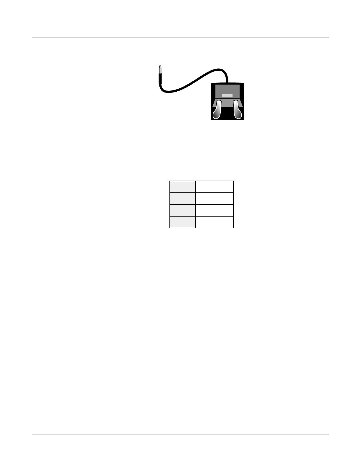
Dual Switch Pedals
e SW1 (SUSTAIN) and SW2 jacks can be connected to dual switch pedals (2 pedals per
jack), allowing up to four switch pedals to be used. Compatible pedals should use a single
1/4 inch tip-ring-sleeve plug.
Pedals plugged into the SW1 (SUSTAIN) jack are referred to as SW1a and SW1b, and
pedals plugged into the SW2 jack are referred to as SW2a and SW2b. In Program Mode the
default assignments are:
SW1a Sustain
SW1b Sostenuto
SW2a Sostenuto
SW2b Soft Pedal
To emulate the 3 pedals of an acoustic piano, plug a single switch pedal into the SW1
(SUSTAIN) jack, and a dual switch pedal into the SW2 jack.
Continuous Switch Pedals (Half-Damper)
e SW1 (SUSTAIN) jack is also compatible with continuous switch pedals (Half-Damper)
that use a 1/4 inch tip-ring-sleeve plug (such as the Kurzweil KP-1H). When connected
to the SW1 (SUSTAIN) jack, a Half Damper pedal enables ner control of Sustain than a
standard switch pedal. Half Damper control is enabled for Programs in the Piano category.
Programs outside of the Piano category will respond to a Half Damper pedal as if it is a
standard switch pedal.
CC1 (VOLUME) and CC2 Jacks
Use the CC1 (VOLUME) jack to connect a MIDI CC pedal (also known as a MIDI
expression or volume pedal). By default this pedal is assigned to control Program and Multi
volume (pre-FX).
For KB3 Organ Programs, the CC1 (VOLUME) pedal controls organ swell. Organ swell is
similar to Program volume, except volume can not be turned all the way down to silence.
e LCD display shows “KB3” when a KB3 Program is selected.
1-10
For User Programs and Multis, the CC1 (VOLUME) and CC2 pedals can be assigned to
dierent functions by using Program Edit or Multi Edit Mode.
Page 20

Getting Started
The Rear Panel
e optional Kurzweil CC-1 continuous control pedal will work best with the PC4, but
it is also possible to use third-party continuous control pedals designed for keyboards.
Compatible pedals should use a 10 kΩ linear-taper potentiometer, with a 1/4 inch tip-ringsleeve (stereo) plug with the wiper connected to the tip.
RIBBON Jack
Use the RIBBON jack to plug in the optional Kurzweil Ribbon Controller. By default the
ribbon controls pitch bend, but you can also program the ribbon controller to send other
MIDI messages. To use the ribbon controller, just press it, and slide your nger along the
ribbon to change the value of the message it’s sending.
You can congure the ribbon to have one control section that runs its entire length, or to
have three sections of equal length. It sends its highest values when you press it at the end
where the cable connects. When you congure it to have three sections, each section sends its
highest values at the end closest to the cable.
Caution: e modular jack is designed for connection to the Kurzweil Ribbon Controller
option only. Don’t plug any other modular plugs into the Ribbon jack.
AUDIO IN LINE/LEFT/RIGHT Jacks
Use the AUDIO IN jacks to mix external audio sources with the sounds of the PC4. is
is useful for playing along with backing tracks from a portable music player, computer, or
other electronic instrument. e LINE jack accepts a stereo 1/8” plug at line level, suitable
for input from MP3 players and computers. e LEFT and RIGHT jacks each accept a 1/4”
plug at line level, suitable for input from mixers and electronic instruments. Sources that are
not line level (typically guitars and microphones) should be amplied with a pre-amp, mixer,
audio interface or other device. Input volume and FX can be adjusted in Global Mode.
AUDIO OUT LEFT (MONO) and RIGHT A/B Jacks
Use the AUDIO OUT A/B jacks to connect to an amplier or mixer. See Quick Start on
page 1-2 for details.
HEADPHONE Jack
Use the HEADPHONE jack located on the left rear panel of the instrument to listen to the
PC4 on stereo headphones. You will need a 1/8-inch-to-1/4-inch adapter in order to use
headphones that have a smaller mini plug connector.
When headphones are plugged in, audio is still transmitted from the AUDIO OUT jacks.
1-11
Page 21

Getting Started
PC4 Sounds
PC4 Sounds
e PC4 contains Programs and Multis. A Program is typically a single instrument sound
such as a Piano, Organ, or Synth. Programs are organized by instrument type in 13
categories.
A Multi is a combination of Programs arranged as layers and/or splits across the keyboard.
Multis are not categorized by instrument type, so the KEYPAD button is always on when in
Multi Mode.
Selecting Programs
In Program Mode, use any of the methods below to select a Program.
Browse All Programs
Make sure the USER button is o, then use the Alpha Wheel or PREVIOUS and NEXT
buttons to select a Program from all of the available Programs.
Select a Program by Category
Make sure the KEYPAD button is o, then press one of the CATEGORY buttons to select
the rst Program of a category (or the current Category Default Program). e selected
CATEGORY button will turn on. Use the Alpha Wheel or PREVIOUS and NEXT buttons
to select Programs from the selected category.
Select a Previously Saved User Program
Press and turn on the USER button, then use the Alpha Wheel or PREVIOUS and NEXT
buttons to browse only User Programs. To return to browsing Factory and User Programs,
press and turn o the USER button.
Select a Program by ID Number
Press and turn on the KEYPAD button. e keypad button allows you to use the numbers
labeled on the CATEGORY buttons to select Programs or Multis by ID number. Type an ID
number followed by pressing the ENTER button to select the associated Program.
Select a Category Default Program
Each category has a Category Default Program (the Program which is selected when each
CATEGORY button is pressed). By default the Category Default Program is set to the rst
Program of each category. To set a dierent Category Default Program, select a Program,
make sure the KEYPAD button is o, then press and hold the currently lit CATEGORY
button.
1-12
Page 22

Selecting Multis
In Multi Mode, use any of the methods below to select a Multi.
Browse All Multis
Make sure the USER button is o, then use the Alpha Wheel or PREVIOUS and NEXT
buttons to select a Multi from all of the available Multis.
Select a Multi by ID Number
Use the CATEGORY buttons to type an ID number followed by pressing the ENTER
button.
Select a Previously Saved User Multi
Press and turn on the USER button, then use the Alpha Wheel or PREVIOUS and NEXT
buttons to browse only User Multis. To return to browsing Factory and User Multis, press
and turn o the USER button.
Getting Started
PC4 Sounds
Controllers
e Sliders, Knobs, Buttons, Wheels, and Pedals can control each of the Factory Programs
and Multis, to produce variations to the sound. Don’t forget to try these out as you explore
the Factory sounds on the PC4.
Generally, each control will perform the assignment labeled on the front panel, although
some controls may have dierent assignments per Program or Multi. When a controller is
moved, the name of the current assignment is shown in the display. Controller assignments
can be adjusted in Program and Multi Edit Mode.
Splits and Layers
e Split and Layer function can be used to Split or Layer the current Program or Multi.
Dierent keyboard regions can play dierent Programs, or multiple Programs can be played
from the same region. To Split or Layer a Multi, it must contain at least one Zone which is
unused (O).
In Program or Multi Mode, press the SPLIT or LAYER soft button to view the Split or Layer
Page. You will then be able to congure up to three additional Programs to create a Split or
Layered Multi containing up to four Programs.
Press the SAVE button once to view the Save Dialog. e Save Dialog allows you to choose
an ID number and name for the Split/Layer Multi you are saving. On the Multi Save Page,
press the SAVE button again to save the Split/Layer Multi. After saving the Split or Layer as a
Multi, additional Multi Controller and FX settings can be edited in Multi Edit Mode.
1-13
Page 23

Getting Started
Modes
Modes
Program Mode
e PC4 always powers up in Program Mode, where single instrument sounds can be played
directly from the keyboard, or multitimbrally via MIDI.
Saving Programs
If you make changes to the current Program using any of the controllers (Knobs, Wheels
or Buttons), the SAVE button turns on to indicate that a change has been made to that
Program.
To save a copy of the Program with the changes you’ve made, press the SAVE button once to
view the Save Dialog. e Save Dialog allows you to choose an ID number and name for the
Program you are saving. On the Program Save Page, press the SAVE button again to save the
Program as a User Program.
Program Edit Mode
Program Edit Mode allows you to select parameters for the assignable knobs, sliders and
buttons, adjust the current Program’s Arpeggiator settings, and adjust many other Program
parameters.
Multi Mode
Multi Mode allows you to play Multis, which are arrangements of up to 16 Programs split
and/or layered in Zones across selected ranges of the keyboard.
By default the volume of the Program in the rst 4 Zones can be easily adjusted while
playing by using the sliders 1-4, and each Zone can be turned on or o by using the
buttons below these sliders. e remaining controls are typically assigned to FX and Synth
parameters. Controller settings can be adjusted in Multi Edit Mode.
Multi Edit Mode
Multi Edit Mode is used to modify the many parameters that make up Multis, including
Program Selection, Key Range, Volume, Pan, and Controller assignments. Use Multi Edit
Mode to create custom sound combinations.
1-14
To save a copy of the Multi with the changes you’ve made, press the SAVE button once to
view the Save Dialog. e Save Dialog allows you to choose an ID number and name for the
Multi you are saving. On the Multi Save Page, press the SAVE button again to save the Multi
as a User Multi.
Page 24

Song Mode
Song Mode allows you to record and play back songs, using up to 16 tracks of Programs.
Global Mode
Use Global Mode to adjust common settings that are shared between all Modes, such as
velocity sensitivity and power saving options. Global Mode is also used for storing or loading
User backup les, and restoring Factory default settings. Some of the more common settings
are summarized below.
Info
e Info Page shows the currently installed operating system and sound object versions. Use
this page to check if your PC4 is up to date with the most recent software and sounds posted
at www.kurzweil.com.
Reset
Getting Started
Modes
You can return the PC4 to the Factory default state by doing a Reset.
Caution: Reset will delete all User objects, so it is important to back up your User objects
before doing a Reset. Factory objects are not deleted.
Saving to External Storage
User objects that you have created can be saved to a USB Flash Drive.
Loading from External Storage
User objects can be loaded onto the PC4 from a USB Flash Drive. is allows you to load
new sounds from Kurzweil or other developers, or to load sounds that you have previously
saved.
1-15
Page 25

Getting Started
Double Button Presses
Double Button Presses
Reset Transposition
To reset the current Program or Multi transposition to 0, simultaneously press both of the
TRANSPOSE -/+ buttons, or the OCTAVE+ and OCTAVE- soft buttons.
Program Demo
In Program Mode, to hear a Program Demo song for the current Program, press the 0/MISC
and ENTER buttons simultaneously.
Song Demo
To hear the capabilities of the PC4, you can play the multi-channel demo songs. Press the
USER and 0/MISC buttons simultaneously to listen to a multi-channel demo song.
Panic
Pressing the ENTER and KEYPAD buttons simultaneously deactivates all sounding notes by
sending an “all notes o” message on all 16 MIDI channels.
Select Channel / Layer / Zone / Track 1
In Program Mode, pressing both of the CHANNEL/LAYER/ZONE/TRACK buttons
simultaneously will select MIDI channel 1.
In Program Edit Mode, pressing both of the CHANNEL/LAYER/ZONE/TRACK buttons
simultaneously will select Layer 1.
In Multi Edit Mode, pressing both of the CHANNEL/LAYER/ZONE/TRACK buttons
simultaneously will select Zone 1.
In Song Mode, pressing both of the CHANNEL/LAYER/ZONE/TRACK buttons
simultaneously will select Track 1
Select Next Unused ID
When selecting an ID number to save a previously saved User object, press the PREVIOUS
and NEXT buttons simultaneously to jump between selecting the previously used ID
number, and the next unused ID number.
1-16
Page 26

Search
e Search page allows you to nd any term or series of characters within the currently
selected list or range of values. Hold the ENTER button and press one of the numeric
buttons 1-9 to view the Search page.
On the search page, use the category buttons to type the term you want to nd, then press
the ENTER button to search. For example, if the program list is selected and you want to
nd all programs containing the word “Horn,” you would type h-o-r-n followed by the
ENTER button. e Search page is not case-sensitive; it will nd upper and lower case
characters regardless of what you type.
After typing a term and pressing the ENTER button, the search page nds and selects
the rst instance of the term in the list (if it exists in the list). To nd and select the next
or previous instance of the term in the list, hold the ENTER button and press one of the
NEXT or PREVIOUS button to search for the next higher-numbered or previous lower
numbered object that contains the search term.
Getting Started
Double Button Presses
Note: Each combination of the ENTER button and a numeric button 1-9 allows you store a
dierent search term. For example, hold the ENTER button and press the 1 button, then
search for a term like “piano”. e term “piano” will now be available whenever you hold the
ENTER button and press the 1 button. Next, hold the ENTER button and press the 2
button, then search for “string”. e term “string” will now be available whenever you hold
the ENTER button and press the 2 button. A dierent term can be stored for each of the
numeric buttons 1-9. ese terms are stored until power o.
1-17
Page 27

Chapter 2
Program Mode
Use Program Mode to play a Program directly from the keyboard, or to play up to 16
Programs multitimbrally via MIDI. Programs typically contain a single instrument sound,
although some Programs may contain multiple instrument sounds.
e PC4 always powers on with Program Mode selected. To enter Program Mode from
another Mode, press and turn on the PROGRAM Mode button, or press the EXIT button
repeatedly until you reach Program Mode.
Program Mode
Selecting Programs
e PC4 powers on with Program 1 selected, or the Program that was selected the last time
Global Mode was exited.
Selecting Programs
In Program Mode, use any of the methods below to select a Program.
Browse All Programs
Make sure the USER button is o, then use the ALPHA WHEEL or PREVIOUS and
NEXT buttons to select a Program from all of the available Programs.
Select a Program by Category
Make sure the KEYPAD button is o, then press one of the CATEGORY buttons to select
the rst Program of a category (or the current Category Default Program). e selected
CATEGORY button will turn on. Use the ALPHA WHEEL or PREVIOUS and NEXT
buttons to select Programs from the selected category.
2-1
Page 28

Program Mode
Program Demo
Select a Previously Saved User Program
Press and turn on the USER button, then use the ALPHA WHEEL or PREVIOUS and
NEXT buttons to browse only User Programs. To return to browsing Factory and User
Programs, press and turn o the USER button.
Select a Program by ID Number
Press and turn on the KEYPAD button. e keypad button allows you to use the numbers
labeled on the CATEGORY buttons to select Programs or Multis by ID number. Type an ID
number followed by pressing the ENTER button to select the associated Program.
Select a Category Default Program
Each category has a Category Default Program (the Program which is selected when each
CATEGORY button is pressed). By default the Category Default Program is set to the rst
Program of each category. To set a dierent Category Default Program, select a Program,
make sure the KEYPAD button is o, then press and hold the currently lit CATEGORY
button.
Program Demo
To hear a Program Demo song for the current Program, press the KEYPAD and ENTER
buttons simultaneously.
2-2
Page 29
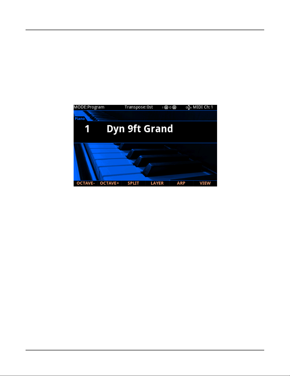
The Display
In Program Mode, the top line of the display shows the current Mode, MIDI transposition,
MIDI In/Out activity indicators, and MIDI channel. If Quick Access view is selected, the
current Quick Access Bank number will be shown instead of the current MIDI channel.
If the currently selected Program is a User Program, the User button will be lit and the
“USER” indicator will appear to the right side of the name. If the currently selected Program
is a KB3 Organ Program, the “KB3” indicator will appear to the right side of the name.
Program Mode
The Display
VIEW Soft Button
Press the VIEW soft button to switch between the default Large view, List view, and Quick
Access view.
MIDI In/Out Activity Indicators
MIDI In/Out activity indicators are displayed at the top of the screen (shown as 2 MIDI
port symbols with “I” for “in” and “O” for “out”). ese indicators briey light up when
MIDI has been recently sent to or received by the PC4’s MIDI/USB ports. If the symbol is
green, this indicates there has been MIDI activity on that port in the last few seconds. If the
symbol is red, this indicates there has been communication with the external software editor
on that port in the last few seconds. If the symbol is grey, this indicates there has been no
MIDI activity on that port in the last few seconds.
2-3
Page 30

Program Mode
Controllers
Controllers
In Program Mode, you can use the PC4 physical controllers (the Knobs, Sliders, Buttons,
Wheels, Pedals, and Ribbon) to modify an instrument sound during a performance to add
variation or expression.
Note: Assigned parameter names are not visible in List view, or if the Global Mode “Show
Controllers” parameter is set to No.
If you make changes to the current Program using any of the controllers, the SAVE button
lights up to indicate that a change has been made to that Program. For more information on
the SAVE button, see Save User Programs on page 2-9.
VAST Program Controller Assignments
In each of the Factory VAST Programs, each control will usually perform the assignment
labeled on the front panel between the Knobs and Sliders. Some controls may have dierent
assignments per Program. When a controller is moved, the name of the current assignment is
shown in the display. Controller assignments can be adjusted in Program Edit Mode.
KB3 Program Controller Assignments
In each of the Factory KB3 Organ Programs, each control will usually perform the
assignment labeled on the front panel below the Sliders. e display shows “KB3” when a
KB3 Program is selected. When a controller is moved, the name of the current assignment is
shown in the display. Controller assignments can be adjusted in Program Edit Mode.
TRANSPOSE Buttons
e TRANSPOSE buttons can be used to change the tuning of notes played on the PC4
keyboard in semitones (also known as half steps). is is a convenient way to change the key
of a song without learning to play it in a dierent key.
e current transpose amount is shown in the LCD display (for example, the default is
“Xp:0st”). Press both TRANSPOSE buttons simultaneously to reset the transposition to 0.
e TRANSPOSE buttons also transpose MIDI notes sent to the USB and MIDI Out ports.
2-4
Page 31

The Split and Layer Soft Buttons
e Split and Layer functions have identical parameters, but produce dierent results.
e Split function allows you to quickly create a Multi such that keys in one range of the
keyboard produce dierent sounds than another range.
e Layer function allows you to layer Programs and Multis such that more than one
instrument sound can be produced by playing one key.
e Split and Layer functions allow you to quickly create Multis without using Multi Edit
Mode to congure Zone key ranges, Programs, and volumes. After creating and saving a Split
or Layer Multi, you can edit additional Multi parameters in Multi Edit mode.
Program Mode
The Split and Layer Soft Buttons
The Split Function
When you create a Split in Program Mode, you are creating a Multi with two Zones set to
On.
e Program you were using in Program Mode is used in the right hand of the Split as the
Zone 1 Program. You can choose a Program that will be used in the left hand of the Split as
the Zone 2 Program.
Follow these steps to create a Split:
1. In Program Mode, select a Program for the right hand of the Split.
2. Press the SPLIT soft button.
3. On the “Split” Page, Zone 2 is selected with a default Bass Program selected for the left
hand of the Split. Use the ALPHA WHEEL or CATEGORY buttons to select a dierent
Program for the left hand of the Split.
2-5
Page 32

Program Mode
The Split and Layer Soft Buttons
4. If desired you may wish to adjust additional Split parameters, described in Split and
Layer Parameters on page 2-6.
5. Press the SAVE button to save your Split as a Multi (See below for details on saving).
After saving your Split Multi, you can edit additional Multi parameters in Multi Edit
mode.
The Layer Function
When you create a Layer in Program Mode, you are creating a Multi with two Zones set to
On.
e Program you were using in Program Mode is used for the Zone 1 Program. You can
choose a Program that will be used as the layered Zone 2 Program.
Follow these steps to create a Layer:
1. In Program Mode, select a Program that you wish to layer.
2. Press the LAYER soft button.
3. On the “Layer” Page, Zone 2 is selected with a default layer Program selected for the
layered Zone 2 Program. Use the ALPHA WHEEL or CATEGORY buttons to select a
dierent Program for the layered Zone 2 Program.
4. If desired you may wish to adjust additional Layer parameters, described in Split and
Layer Parameters on page 2-6.
5. Press the SAVE button to save your Layer as a Multi (See below for details on saving).
After saving your Layer Multi, you can edit additional Multi parameters in Multi Edit
mode.
Split and Layer Parameters
ere are ve parameters (described below) that determine the behavior of Splits and Layers.
Use the cursor buttons to access each of the parameters for each active Zone.
Status (Zone Status)
You can activate additional Zones with the Status parameter or the buttons in the front panel
CONTROL section.
Program
2-6
Use the Program parameter to select a Program for each Zone. Use the Category buttons,
the Alpha Wheel, the Previous/Next buttons, or enable the Keypad button and type an ID
number followed by the Enter button.
Page 33

Program Mode
The Split and Layer Soft Buttons
Volume
To change the volume of a Zone, use the cursor buttons to select the Volume parameter for
one of the Zones. To set a volume, use the Alpha Wheel, the Previous/Next buttons, or use
the keypad function of the Category buttons to type a volume (0-127) followed by the Enter
button.
A value of “None” will use the last volume value used by the Zone’s MIDI channel (often set
by the expression pedal). A value of “None” can be entered by scrolling below 0, or by using
the keypad function of the Category buttons to type negative 1 by pressing the small +/button and then the 1 button, followed by the Enter button.
Key Range
You can adjust the boundary between the left and right hand Programs on the keyboard by
adjusting the Key Range low and Key Range high parameters for each Zone. e keyboard
display for each Zone shows a visual indication of the Key Range by dimming keys that are
outside of the Key Range.
To change the Key Range of a Zone, use the cursor buttons to select the Key Range low or
Key Range high parameters for one of the Zones. Key Range low and Key Range high are
the left and right parameters, respectively, below the Key Range label. With one of these
parameters selected, set the Key Range by using the Alpha Wheel, the Previous/Next buttons,
or use the keypad function of the Category buttons to type a key number (0-127) followed
by the Enter button. With Key Range low or Key Range high selected, the value can also be
changed by holding the Enter button, then pressing the desired key.
Pan
To change the panning of a Zone (left/right stereo placement), use the cursor buttons to
select the Pan parameter for one of the Zones. To set a Pan value, use the Alpha Wheel, the
Previous/Next buttons, or use the keypad function of the Category buttons to type a pan
value (0-127) followed by the Enter button. A value of 0 is full left, 64 is center, and 127 is
full right. Other values will move the stereo placement in between these positions. A value of
“None” will use the last pan value used by the Zone’s MIDI channel.
A value of “None” can be entered by scrolling below 0, or by using the keypad function of
the Category buttons to type negative 1 by pressing the +/- button and then the 1 button,
followed by the Enter button.
Saving a Split or Layer
After setting the Split or Layer parameters, your changes can be saved as a Multi that it can
easily be recalled in Multi Mode. Press the Save button to the left of the display to begin
the saving process. A Multi name is automatically created using half of the original Program
name and half of the default Zone 2 program name. is name can be edited during the
saving process.See Saving a User Multi on page 6-10 in the Multi Mode Chapter for details
on saving.
2-7
Page 34

Program Mode
Changing the MIDI Channel
Once you have saved your Split or Layer as a Multi, you can continue to add additional
Zones, edit controller assignments (like eects controls and sustain pedal per Zone),
transposition per Zone, and other Multi parameters. (See Ch. 7 Multi Edit Mode for
details.)
Changing the MIDI Channel
e current MIDI channel is shown on the right side of the top line of the display. Press the
CHANNEL/LAYER/ZONE/TRACK Up or Down buttons to change the MIDI channel.
Pressing both of the CHANNEL/LAYER/ZONE/TRACK buttons simultaneously will select
MIDI channel 1.
A dierent Program can be selected for each MIDI Channel. All channels can be triggered
simultaneously from an external MIDI sequencer or computer.
Note: e Aux FX Chains of the Program on the currently selected MIDI channel are used
for Programs on all Channels.
Panic
Pressing the ENTER and KEYPAD buttons simultaneously deactivates all sounding notes by
sending an “all notes o” message on all 16 MIDI channels.
2-8
Page 35

Save User Programs
If you make changes to the current Program using any of the controllers, the Save button’s
LED lights to indicate that a change has been made to that Program.
To save a copy of the Program with the changes you’ve made, press the Save button once to
view the Save Dialog. e Save Dialog allows you to choose an ID number to that will be
associated with the program you are saving. When viewing the Save Dialog, you can quickly
save the Program to the displayed ID number by pressing the Save button again.
Changing ID Numbers
e display shows the rst available ID number and the current Program name. User
Programs can be saved to ID numbers from 4096 to 8191.
Program Mode
Save User Programs
If you are saving a Program that has not been previously edited, the next available unused ID
number will be selected.
If you are saving a previously edited User Program, the ID number that the Program was last
saved with will be selected.
Press the Previous and Next buttons simultaneously to toggle between selecting the ID
number that the Program was last saved with and the next available unused ID number.
To change the ID number, turn the Alpha Wheel or use the Previous/Next buttons to select
the new ID number. e label underneath indicates if it is an “Unused ID”. You can also use
the keypad function of the Category buttons to type an ID number, followed by pressing the
Enter button
If you select an ID currently in use, the display will notify you that by saving you will
“replace” the Program currently in that location. Conrm overwriting of the existing
Program by pressing Save, or choose a dierent ID.
2-9
Page 36

Program Mode
Save User Programs
Naming a User Program
To rename the Program, rst press the RENAME soft button. e display shows the current
Program name.
Use the Category buttons, Alpha Wheel or Previous/Next buttons to change each character.
Use the Left/Right cursor buttons or <<< >>> soft buttons to move the cursor.
Press the +/- button to switch between upper and lower case characters.
Use the Insert button to insert a blank space. e selected character and all characters to the
right will move one space to the right.
Use the Delete button to delete the current character (all the characters to the right will move
one space to the left).
Saving a User Program
Press the Save button or Save soft button to complete the saving process, or press the Cancel
soft button to exit without saving. After successfully saving, the Program will be selected in
Program Mode.
To nd the Program again later, press the User button and scroll to the Program ID. You
can also nd the program by pressing the appropriate Category button and scrolling past
the factory programs. Lastly, you can press the Keypad button so that its LED is lit, type the
Program ID number, then press the Enter button.
2-10
Page 37

Chapter 3
Program Edit Mode
Program Edit Mode allows you to edit and customize Programs. Any Program can be edited
in Program Edit Mode and saved to a User ID.
To enter Program Edit Mode, rst press the PROGRAM Mode button to enter Program
Mode, then press the EDIT button.
Program Edit Mode
Program Types
Program Types
e PC4 contains VAST and KB3 Programs.
VAST Programs can use layers of samples and synthesis suitable for generating a wide variety
of traditional instrument sounds, as well as synthesizer sounds. For details on editing VAST
programs, see Editing VAST Programs on page 3-2.
KB3 Programs contain a set of oscillators designed to emulate the tone wheels in a classic
tone wheel organ. For details on editing KB3 programs, see Editing KB3 Programs on page
3-105.
3-1
Page 38

Program Edit Mode
Editing VAST Programs
Editing VAST Programs
VAST Program Features
VAST programs can utilize many common synthesizer features, in addition to some
uncommon features. Some notable features:
• KDFX: Each of the 32 possible VAST layers can be individually processed by a layer
insert FX Chain. All Layers can be processed a common insert FX Chain and two
common Aux FX Chains.
• Intonation and Tuning Maps: Each VAST program can have its own Intonation
Map (tuning repeated across each octave) and Tuning Map (tuning per note).
• KSR: Kurzweil Piano String Resonance Simulation.
• CC Sequencer: A step sequencer to control synthesizer parameters.
• KVA Oscillators: Anti-aliased synthesizer oscillators.
• Cascade Mode: Route the audio of any of the 32 layers of a program into the DSP
ALG of any other layer.
• Dynamic VAST: Combine dierent DSP functions in any order you like, including
parallel and serial congurations.
• FM Layers: FM layers contain a set of oscillators designed to emulate classic 6
operator FM synthesizers.
VAST Program Structure
e diagram below depicts the hierarchy of a VAST program, from individual samples all the
way up to Multis, which can contain up to 16 programs.
Every VAST program contains at least one layer (32 layers maximum). Each layer can use a
keymap of samples or a synth oscillator as sound sources. e sound sources in each layer can
be individually processed with an algorithm containing DSP functions. Each Layer can also
be individually processed by a layer insert FX Chain. All Layers can be processed a common
insert FX Chain and two common Aux FX Chains.
Each VAST layer uses one of the 256 voices of the PC4 (two voices for stereo samples). Each
FM layer uses 4 voices.
3-2
Page 39

MULTI
Program Mode
VAST Program Structure
Zone1Zone2Zone3Zone4Zone5Zone6Zone7Zone
8
16 keyboard zones—
each with independent
program, MIDI channel,
and control assignments
Selected for performance
and editing in Program
mode; up to 32 layers per
program
A keymap processed
through an algorithm,
modulated by control
sources
Up to 128 sample
roots, assigned to play
at programmable key
and velocity ranges
Individual digital sound
recordings stored in
ROM; stereo samples
use two voices of
polyphony
Program Edit Mode
Editing VAST Programs
16 keyboard zones—
each with independent
program, MIDI channel,
and control assignments
PROGRAM
ALGORITHM
KEYMAP
Selected for performance
and editing in Program
mode; up to 32 layers per
program
A keymap processed
through an algorithm,
modulated by control
sources
Up to 128 sample
roots, assigned to play
at programmable key
and velocity ranges
SAMPLE ROOTS
Individual digital sound
recordings stored in
ROM; stereo samples
use two voices of
polyphony
Note: When using a KVA oscillator, the sound source for that layer is generated at the
algorithm stage. See Editing VAST Programs With KVA Oscillators on page 3-73 for more
details.
3-3
Page 40

Program Edit Mode
Navigation
Navigation
Press the soft buttons at the bottom of the screen to navigate to each page, or to perform the
labeled function.
Use the cursor buttons to select each parameter, and the PREVIOUS/NEXT buttons, Alpha
Wheel, or CATEGORY buttons to change each value.
When certain parameters are selected, additional editor pages or functions can be accessed by
pressing the EDIT button. e EDIT button lights up when the EDIT button can be used.
Soft Buttons in the Program Editor
Press the soft buttons at the bottom of the screen to navigate to each page, or to perform the
labeled function.
Press the MORE soft buttons to view more sets of soft buttons.
See the rest of this chapter for details on each of the Program Edit Mode pages.
See “The Soft Button Functions” on page 3-70 for details on soft button functions in
Program Edit Mode pages.
Layers
Use the CHANNEL/LAYER/ZONE/TRACK buttons to change the current Layer. Most
parameters apply only to the currently selected Layer, which will be shown in the top right
corner of the display.
Parameters on the PARAMS Page, FX Page, COMMON Page and ARP Page apply to all
Layers.
The EDIT Button in the Program Editor
When certain parameters are selected, additional editor pages or functions can be accessed by
pressing the EDIT button. e EDIT button lights up when the EDIT button can be used.
Sub Editors
Press the EDIT button to enter sub editors when the following elds are selected:
• Parameters on the PARAMS page
3-4
• FX Chains on the FX or LYR FX pages
• Intonation Maps on the COMMON page
• Keymaps on the KEYMAP page
• Samples within the Keymap editor
Page 41

Jump
When a Program Edit source eld is selected and assigned to a physical controller or CC
number, press the EDIT button to jump to the associated parameter on the Parameters Page.
When a Program Edit source eld is selected and assigned to an envelope, LFO, ASR or
FUN, press the EDIT button to jump to an associated eld on the envelope or LFO+ pages.
Assign
Assign is the secondary function of the ENTER button. You can use the Assign function to
quickly select parameters or set values for parameters by holding the ENTER button while
moving PC4 controllers (Knobs, Sliders, Buttons, Keys, Wheels, and Pedals).
Parameters that can use the Assign function are indicated by showing the Assign symbol in
the top right corner of the display when selected.
Program Edit Mode
Navigation
• Patterns on the ARP page (Shift, Velocity, and Duration)
• Algorithms on the ALG page
Select an Assigned Parameter
When the PARAMS Page Parameter column is selected, hold the ENTER button and move
a controller to select the assigned parameter (if a parameter is assigned to that controller).
is is an easy way to check if a controller is unused, or is already being used by a parameter.
Assign a Physical Controller
When the PARAMS Page Control column or a Program Edit source eld is selected, hold the
ENTER button and move a physical controller to assign the moved controller to the selected
parameter or source eld.
Assign a Control Source
When a Program Edit source eld is selected, hold the ENTER button and press one of the
keyboard keys. Each of the 88 keys will select one of the available control sources.
Select a Key Range
When the LAYER Page Low Key or High Key elds are selected, hold the ENTER button
and press a keyboard key to set the Low Key or High Key.
3-5
Page 42

Program Edit Mode
The PARAMS Page
The PARAMS Page
e PARAMS page shows all Program and FX parameters for the current program that have
been assigned to be controlled by the PC4’s physical controllers, or by MIDI CCs from an
external MIDI device.
Use the PARAMS page to change controller and MIDI CC assignments, set an initial
MIDI value for each controller assignment, and edit the name displayed for each controller
assignment.
When controller or MIDI assignments are made on other Program or FX Edit pages, or
if an FX Chain is selected which contains controller assignments, these parameters are
automatically added to the Parameters page.
3-6
Parameter Column
e Parameter column shows all Program and FX parameters for the current program that
have been assigned to be controlled by the PC4’s physical controllers, or by MIDI CCs from
an external MIDI device.
Eect Chain parameters are named with prexes based on their eect type: “INS” for
parameters from Insert eects, “LFX” for parameters from layer eects, and “AUX1” or
“AUX2” for parameters from Aux eects.
To quickly nd a parameter that is already assigned to a controller, select the parameter
column, hold the ENTER button and move a controller to select the assigned parameter.
Page 43

Control Column
e Control column determines which physical controller (or external MIDI CC number)
will control the parameter in the selected row. To quickly assign one of the PC4’s physical
controllers to a parameter, select the control column in the row of the desired parameter,
hold the ENTER button and move the desired controller. Alternatively, you can use the
Alpha Wheel or the Previous/Next buttons to select a controller from the list, or type in
the controller’s MIDI number followed by the ENTER button. See below for a list of PC4
physical controllers and their associated MIDI numbers.
If you want to disable the controller for a parameter, you can select a value of None by
scrolling to the bottom of the controller list (using the Alpha Wheel or the Previous/Next
buttons), or type -1 followed by the ENTER button.
To choose an external MIDI CC number as a control source, you can enter the number of
the controller followed by the ENTER button, or use the Alpha Wheel or the Previous/Next
buttons. e PC4’s physical controllers each use one of the available MIDI CC numbers,
so you must choose one of the other available CC numbers when using an external MIDI
control source or else the parameter will also be controlled by a PC4 physical controller.
MIDI CC numbers associated with the PC4’s physical controllers are shown in the list below.
Program Edit Mode
The PARAMS Page
PC4 Physical Controller MIDI CC Numbers
Mod Wheel (MIDI CC 1) Slider 4 (MIDI CC 23) Knob 3 (MIDI CC 72)
Knob 8 (MIDI CC 3) Slider 5 (MIDI CC 24) Knob 2 (MIDI CC 73)
CC Pedal 2 (MIDI CC 4) Slider 6 (MIDI CC 25) Knob 4 (MIDI CC 79)
Knob 9 (MIDI CC 9) Slider 7 (MIDI CC 26) Switch 1 (MIDI CC 80)
CC Pedal 1 (MIDI CC 11) Slider 8 (MIDI CC 27) Switch 2 (MIDI CC 81)
Slider 1 (MIDI CC 12) Slider 9 (MIDI CC 28) Switch 3 (MIDI CC 82)
Slider 2 (MIDI CC 13) Variation Button (MIDI CC 29) Switch 4 (MIDI CC 83)
Knob 5 (MIDI CC 14) Sw. Pedal 1a (MIDI CC 64) Switch 5 (MIDI CC 85)
Knob 6 (MIDI CC 17) Sw. Pedal 1b (MIDI CC 66) Switch 6 (MIDI CC 86)
Knob 7 (MIDI CC 18) Sw. Pedal 2a (MIDI CC 66) Switch 7 (MIDI CC 87)
Ribbon Section 1 (MIDI CC 21) Sw. Pedal 2b (MIDI CC 67) Switch 8 (MIDI CC 89)
Slider 3 (MIDI CC 22) Knob 1 (MIDI CC 71) Switch 9 (MIDI CC 90)
3-7
Page 44

Program Edit Mode
The PARAMS Page
Value Column
To change the value of a parameter, use the cursor button to highlight the right column. In
the value column, use the Alpha Wheel or the Previous/Next buttons to enter a MIDI value
from 0-127, or a value of None by scrolling below 0. You can also use the keypad function
of the Category buttons followed by the ENTER button to enter a MIDI value. If you set
a MIDI Value to None by scrolling below 0, the MIDI value will be 0 until you change the
value with an assigned controller (though None will still be displayed). A value of None can
also be selected by using the keypad to type -1, followed by the ENTER button.
Important Note: Values of “None”
For factory programs, standard parameters like Expression (program volume), Sustain,
and Sostenuto are always set to None by default. If you change one of these values, either
on the PARAMS page in the Program Editor, or with a physical controller from Program
Mode (or the Program Editor,) the same value will be used for any other program you
select, if you select another program that uses a value of None for the same parameter.
ese values remain set even if you don’t save the program.
is can be useful, for example, when using an expression pedal to control program
volume. By default, all factory programs have their Expression parameter set to a value of
None, and Expression (program volume) by default can be controlled by an expression
pedal plugged into the CC 1 Pedal jack. With an expression pedal plugged into the CC
1 Pedal jack, you can control the volume of any factory program, but when you select
another factory program, it will have the same volume that you set with the expression
pedal in the last program. is way, the volume of your programs will stay consistent,
and can always be changed by the expression pedal. If you want a program to have a
default volume, you must set a Value other than None for the Expression parameter.
For all parameters with a Value of None, any values set with a physical control
will not be saved when saving the program. You must set the Value column for
that parameter to something other than None in order to set and save a value.
ese values will remain set until changed with a controller, or until a program is
loaded on the current MIDI channel that does not have a value of None for these
parameters.
3-8
Page 45

Parameter Edit
Select a Parameter and press the EDIT button to view the Parameter Edit page. e
Parameter Edit page allows you to view the Parameter’s Destination, Entry Value, Control,
and Text name. e parameter name can be edited, see below for details.
Press the BACK soft button to return to the PARAMS page, or press the DELETE soft
button to delete the current Parameter.
Program Edit Mode
The PARAMS Page
Destination
A parameter’s Destination is automatically set when the Parameter is created, and can not be
changed. A PARAMS page Parameter will control any Program Edit or FX Edit parameter
which has it’s source eld set to the same destination number. For details see “PARAMS
Page Parameter Destination” on page 3-12.
Entry Value and Control
ese parameters are equivalent to the PARAMS page Value column and Control column.
Text
To change the Parameter’s name, use the Navigation buttons to select the Text eld, then
press the EDIT button to enter the Parameter Name page, where you can rename the
Parameter. Use the Navigation buttons and soft buttons to change the Parameter name. Press
OK to save the new parameter name, or CANCEL to return to the previous page.
3-9
Page 46

Program Edit Mode
The PARAMS Page
Adding Parameters to the PARAMS Page
To add parameters to the PARAMS page, a controller assignment must be made using a
source eld on one of the Program Edit or FX Edit pages. Controllable parameters each have
a source eld. All source elds are listed below:
VAST Program Source Fields
The FX Page on page 3-13
• Mod
The Layer FX (LYR FX) Page on page 3-16
• Aux1 Mod, Aux2 Mod
The KEYMAP Page on page 3-39
• Alt Control
The LAYER Page on page 3-44
• Enable
The DSP Modulation (DSP MOD) Page on page 3-55
• Source 1, Source 2, Depth Ctl
The OUTPUT Page on page 3-57
• Mod
Envelope Control on page 3-62
• Source
The LFO+ Page on page 3-66
• RateCt, Trigger, Input a, Input b
FM Operator Page on page 3-84
• Level Source 1, Level Source 2, Freq Source 1, Freq Source 2
FM Amp + Output Page on page 3-95
• Source 1, Source 2, Crossfade
FM Alt Input Page on page 3-98
• Source 1, Source 2
KB3 Program Source Fields
3-10
KB3 Editor: The PITCH Page on page 3-112
• Source 1, Source 2
Page 47

Program Edit Mode
The PARAMS Page
KB3 Editor: The AMP Page on page 3-112
• Source 1, Source 2
KB3 Editor: The LFO+, ARP and CC SEQ Pages on page 3-117
• RateCt, Trigger, Input a, Input b
Chain Edit Source Fields
The MOD Pages on page 4-3
• Source
FXLFO+ page on page 4-5
• RateCt, Trigger, Input a, Input b
Adding Physical Controllers
To assign a PC4 physical controller, select the source eld for the parameter, hold the
ENTER button and move the controller.
Adding MIDI CC Numbers
To assign a CC number to a source eld, enter a number from 1-31 or 64-95 with the
alphanumeric pad, then press Enter. A CC number for an external controller can also be set
by selecting the source eld for the parameter, holding the ENTER button, and sending a
CC value from the external MIDI controller.
Note: e PC4’s physical controllers each use one of the available MIDI CC numbers, so
you must choose one of the other available CC numbers when using an external MIDI
control source or else the parameter will also be controlled by a PC4 physical controller. See
the PC4 Physical Controller MIDI CC Numbers on page 3-7 for a list of CC numbers
used by the PC4’s physical controllers. Some MIDI CCs are also hard wired to control
certain program parameters or functions such as MIDI 5 (Portamento Time), MIDI 7
(Program Volume), MIDI 10 (Pan), MIDI 11 (Expression/Program Volume), MIDI 64
(Sustain), MIDI 66 (Sostenuto), so if you use one of these numbers the CC will always
perform the hard wired function, in addition to any other assignment you make.
3-11
Page 48

Program Edit Mode
The PARAMS Page
Program Edit Source Names
When assigning a physical controller or CC number to a Program Edit source eld, the
source eld will show a default MIDI CC number (the destination), followed by the assigned
physical controller name or MIDI CC number (the control name). For example assigning
Slider 1 shows “12 Slider 1”, and assigning MIDI CC 5 shows “5 MIDI 5”).
Note: If a parameter assignment is changed on the PARAMS page using the Control
column, the Program Edit source eld will update the control name, while maintaining the
same destination number. For example, in a clear Program assign the DSP MOD page Pitch
Source 1 to “12 Slider 1”. A “Pitch” parameter will appear on the Parameters page, with its
Control set to Slider 1. On the PARAMS page, change Pitch Control column to Slider 2.
e DSP MOD page Pitch Source 1 eld will now show “12 Slider 2”.
PARAMS Page Parameter Destination
On the PARAMS page, press the EDIT button to see a Parameter’s Destination eld. A
parameter’s Destination is automatically set when the Parameter is created, and can not be
changed.
A PARAMS page Parameter will control any Program Edit or FX Edit parameter which has
it’s source eld set to the same destination number. When an assigned Program Edit source
eld is selected, you can jump to selecting the controlling PARAMS page parameter by
pressing the EDIT button.
PARAMS Page Parameter Shared Assignments
When assigning a physical controller or CC number to a source eld, a Parameter is
automatically added to the PARAMS Page with the name of the rst assigned Program Edit
parameter.
If you assign a source eld to a destination number that is already used by a parameter
on the PARAMS page, a new parameter will not be added to the PARAMS page. e
new assignment will share the existing Parameter on the PARAMS page (Name, Control
assignment and initial Value). e existing Parameter will control multiple assignments, but
the existing Parameter’s name will not change to reect this. You can edit the Parameter name
by selecting the Parameter and pressing the EDIT button to access the parameter edit page.
See Parameter Edit on page 3-9 for details.
3-12
Page 49

The FX Page
Use the FX page to apply audio eects to a Program. You can select an Insert eects Chain
and 2 Aux eects Chains, all of which apply to all layers in the Program (unless Layer FX are
used, see below for details). In Program Mode, Programs on all MIDI channels share the Aux
chains of the Program on the currently selected MIDI channel.
Program Edit Mode
The FX Page
e PC4’s Chains contain a variety of eects. Each Chain displays icons representing the
type of eects contained in the Chain, as well as the order of eects in the Chain (signal
ows from left to right). e PC4’s Chains include dierent types of reverb, chorus, delay,
anger, phaser, tremolo, panner, rotary, distortion, EQ, compression, lter, envelope
following lter, frequency stimulator, ring modulator, frequency oset, pitch LFO, and
stereoizer.
e selected Chain can be edited by pressing the EDIT button. See Ch. 4 The Effects
Chain Editor for details.
DSP Resources and DSP Units
A Program can have up to 8 Insert Chains (any combination of common and layer specic
inserts) and 2 Aux Chains.
e PC4 has 32 “units” of eects resources that can be used to load eects chains. Each FX
chain requires a certain number of FX units in order to load, depending on its complexity.
e top line of the display shows a fraction with the number of units used by the selected
channel, over the total number of units used. When attempting to use more than 32 units of
FX resources at once, some FX Chains will not be loaded.
3-13
Page 50

Program Edit Mode
The FX Page
When sustaining notes while switching between 2 Programs, FX resources from the rst
Program may be “stolen” in order to load eects from the second Program. Because of this,
you may hear a change in the sound of the rst Program when switching to the second
Program. If both Programs each use 14 DSP Units or less, then in most cases FX resources
will not be stolen from the rst Program, and you should not hear a change in the sound of
the rst Program.
Insert
Choose an eects Chain that will be applied to the current program. If you only need to use
one Chain at a time on one MIDI channel, Insert eects may be all you need. If you plan
to use multiple programs on dierent MIDI channels, it is best to use both Insert and Aux
eects (see Aux below). Aux eects have the advantage of being available to all programs on
each MIDI channel at the same time.
Aux 1, Aux 2
Choose an eects Chain for each of the two auxiliary audio buses. An aux bus is an audio
channel with a shared eects Chain that can be used by programs on any of the 16 MIDI
channels. e aux eect is useful when you want to use the same type of eect for multiple
channels (typically used for Reverb or Delay). You apply an aux eect to the program on a
MIDI channel by “sending” the audio from that channel to an aux bus.
Every channel is connected to the aux buses, but the aux buses don’t receive the signal until
you turn up the aux “send” level for that channel, which controls a channel’s input level to
the aux bus. On each MIDI channel you can control the aux send level for that channel’s
program, in turn controlling how loudly you can hear the aux eect applied to that channel’s
program. e aux send level is set by the Aux 1 and Aux 2 Send parameters on the FX page.
Many Chains also have an additional Aux send, Wet/Dry, or Amount parameter that will
appear on the PARAMS page. For Reverb and Delay Chains, send parameters are often
assigned by default to Slider 9 or Slider 8 respectively.
Output
e Output parameter species the rear panel analog output pair to which the selected aux
bus is routed. Setting the Output to A routes the signal of the selected bus to output pair A.
Setting the Output to B routes the signal of the selected bus to output pair B. is is useful
if you want to control the processed Aux signal with an external mixer or process the signal
with additional external eects.
3-14
Page 51

Send
e Aux Send parameters determine how much of the Program’s signal is sent to each Aux
FX Chain. Depending on the Type parameter, the send values are set either in dB or wet/dry
percent.
Pre/Post
e Aux Pre/Post parameters determine whether or not the output of the Insert chain is sent
to each Aux Chain (the “pre” or “post” insert signal).
When set to Pre, the output of the Insert chain is not sent to the Aux Chain.
When set to Post, the output of the Insert chain is sent to the Aux Chain.
Type
e Type parameter determines the values used for each Send parameter (dB or percent), and
whether or not each send will work as a wet/dry control.
Program Edit Mode
The FX Page
Mod
When Type is set to dB, the Aux send level is set in dB and works like a traditional send on
an audio mixing board. As you turn up the Aux send, the Aux Chain’s processed wet signal
is layered over the program’s unprocessed dry signal. Setting Type to dB is useful for setting a
precise send value. e level of signal sent to the Chain is set in dB, the higher the value the
more processed signal you will hear.
When Type is set to %, the Aux send level is set in % and works as a dry/wet mix. As you
turn up the Aux send, the Aux Chain’s processed wet signal is turned up and begins to
replace the program’s unprocessed dry signal, which is turned down. For example, with an
Aux send set to 50% you hear an equal amount of unprocessed (dry) and processed (wet)
signal. With an Aux send set to 100% you hear only the processed (wet) signal and none of
the original unprocessed (dry) signal. Typically it’s best to set Type to % when a continuous
controller (like a Slider) is assigned to the Mod parameter, because it will give the controller
more usable range then when set to dB.
Use each Mod parameter to select a physical controller or other control source to adjust each
Aux Send value. e selected Mod control source will adjust the Send level using the range
set by the Send parameter.
3-15
Page 52

Program Edit Mode
The Layer FX (LYR FX) Page
The Layer FX (LYR FX) Page
Use the Layer FX page to apply audio eects to individual layers of a Program.
Layer FX Mode
Select a Layer FX Mode to determine how eects will be applied to each layer. See below for
details on each mode:
Use Program FX
With Use Program FX selected, the current layer will use the eects congured on the FX
page. See The FX Page above for more information on program FX.
Layer-Specic FX
With Layer-Specic FX selected, you can congure the eects for the current layer. A
Program can have up to 8 Insert Chains (any combination of common and layer specic
inserts).
e Layer specic parameters are the same as on the FX page, except they apply only to the
current layer, and some of the Aux parameters are not available (the settings from the FX
page are used for the Aux 1 and Aux 2 Chain and Output parameters). See The FX Page
above for more information on these parameters.
In this mode, the Aux parameters on this page apply to the Aux Chains selected on the FX
page.
3-16
Use Another Layer’s FX
With Use Another Layer’s FX selected, you can put the current layer through the Insert
Chain and Aux eects settings of another layer. Use the “Use FX From Layer” parameter to
select the layer whose eects you wish to use.
Page 53

The COMMON Page
e Common Page contains parameters that eect all layers of the current Program.
Program Edit Mode
The COMMON Page
BendRange Up & BendRange Down
Use these parameters to dene how much the pitch will change when you move the Pitch
Wheel. Pitch values are set in cents, where 100 cents = 1 half-step (1 semitone).
For both Bend parameters, positive values will cause the pitch to bend up, while negative
values will cause the pitch to bend down. Large positive values can cause samples to bend
to their maximum upward pitch before the Pitch Wheel is fully up (or down). is will not
happen when bending the pitch down.
Output Gain
Use the Output Gain parameter to cut or boost the nal gain stage of the post-FX program
signal. is is useful for adjusting the overall volume of a program.
Category
is parameter sets the category that the program will be grouped into when you press one of
the Category buttons from the Program mode main page.
Intonation Map
e Intonation Map parameter allows you to set a dierent intonation map for each
program. You can edit the currently selected map and save it as a user map by pressing the
EDIT button.
3-17
Page 54

Program Edit Mode
The COMMON Page
e Intonation Map parameter works just like the Global mode Intonation Map parameter,
except the Intonation Map parameter on the Program Common page only applies to the
current program. (e Global mode Intonation Map parameter applies to all programs.) See
Editing Intonation Maps on page 9-12 for more details on intonation maps.
Intonation Key
e Intonation Key parameter allows you to set a dierent Intonation Key for each program.
e Intonation Key parameter works just like the Global mode Int Key parameter, except
the Intonation Key parameter on the Program Common page only applies to the current
program. (e Global Mode Int Key parameter applies to all programs.) See Editing
Intonation Maps on page 9-12 for more details on intonation keys.
Monophonic
When the Monophonic parameter is set to “O”, the current edited program is
polyphonic—it can play multiple notes at a time.
When the Monophonic parameter is set to “On”, the program will play only one note at
a time, and the Legato parameter and the four Portamento parameters will appear on the
Program Common page. e Monophonic, Legato and Portamento parameters are not
available for KB3 programs.
Legato
When the Monophonic parameter is set to “On”, the Legato parameter appears. e Legato
parameter is useful for emulating legato techniques of various acoustic instruments. When
the Legato parameter is set to “On”, a played note will trigger a new amplitude envelope only
if no other notes in the program are being held. Notes played while other notes are being
held will use the previously triggered amplitude envelope of the rst note that was played.
3-18
Page 55

Portamento
When the Monophonic parameter is set to “On”, the Portamento parameter appears.
When the Portamento parameter is set to “On”, notes played in a monophonic Program can
glide from the pitch of the previously played note to the pitch of the currently played note.
Portamento is often used in synthesizer lead sounds, or to mimic acoustic instruments like
violin and bass, where a pitch glide is achieved by sliding a nger along a vibrating string.
See Portamento Rate (below) to set the Portamento glide speed, and Attack Portamento
(below) to set the way that Portamento responds to played notes. See the Mono Sample
XFade parameter (below) to improve the sound of Portamento in programs that use multiple
samples.
Portamento Rate
When the Portamento parameter is set to “On”, the Portamento Rate parameter appears.
e Portamento Rate parameter determines how fast a note glides from the pitch of one
note to the pitch of the next played note. e value selected for this parameter determines
how many seconds a note takes to glide one semitone (half-step) toward the pitch of the
next played note. For example, at a setting of 12 keys/second the pitch would glide an octave
every second. Select a higher value for a faster pitch glide, or a lower value for a slower pitch
glide. e list of values is nonlinear; that is, the increments get larger as you scroll to higher
values.
Program Edit Mode
The COMMON Page
Portamento Attk
is parameter toggles between two types of portamento. When set to On, the pitch always
glides to each new note played from the pitch of the last note played. When set to O, the
pitch glides to each new note played only if the last note played is still being held. is is
useful when you want only some notes to use portamento.
Mono Sample XFade
When applying portamento to programs that use multiple samples (Acoustic Guitar, for
example), the PC4 will play more than one sample root as the pitch glides from the starting
pitch to the ending pitch. is may cause a small click at each sample root transition. You
can eliminate clicks by setting the Mono Sample XFade parameter to On. When the Mono
Sample XFade parameter is set to On, the PC4 performs a crossfade at each sample root
transition to eliminate clicks.
3-19
Page 56

Program Edit Mode
The COMMON Page
Out Pan
Use the Out Pan parameter to adjust the left/right balance of the entire Program output
signal (post-FX). Negative values pan the audio signal to the left channel, positive values to
the right, and a value of zero pans to the center.
Out Pan Mode
When the Out Pan Mode is set to Fixed, the Out Pan position remains as dened with the
Out Pan parameter, ignoring MIDI pan messages. When the Out Pan Mode is set to +MIDI,
MIDI pan messages (MIDI 10) will shift the sound to the left or right of the Pan parameter
setting. Message values below 64 shift it left, while those above 64 shift it right.
Globals
is parameter aects the control sources LFO2, ASR2, FUN2 and FUN4.
When the Globals parameter is set to O, these control sources are local; they aect each
note individually in the layers that use them as a control source. ey begin operating for
each note each time a note in that layer is triggered, and are not aected by other notes.
When the Globals parameter is set to On, these control sources become global, which means
they aect every note in every layer of the current program, they’re not specic to any one
layer. When these control sources are global, they begin operating as soon as the program is
selected. When Globals are on, LFO2, ASR2, and FUNs 2 and 4 will appear on the LFO+
page preceded by the letter G to indicate that they’re global.
Local control sources are useful for aecting parameters independently for each note in a
layer. Local control sources have the advantage of having a separate copy re-triggered for each
note. eir disadvantage is that their parameters must be set separately for each layer if you
wish to aect multiple layers.
Global control sources are useful for aecting many parameters in a program uniformly,
because they share the same settings on all layers. eir disadvantage is that a separate copy
in not re-triggered for each note.
You’ll use global control sources when you want to aect all notes in a program uniformly,
and local control sources when you want to aect each note independently. For example,
a global LFO is useful for controlling amplitude to create a tremolo eect, if you want the
eect applied uniformly to all the notes you play. A local ASR is useful for controlling the
frequency of a lter sweep, if you want the lter sweep to be independent for each note.
3-20
Page 57

Demo Song
e Demo Song parameter allows you to choose the demo song for the current program.
e demo song is a short, pre‐programmed song that gives you a demonstration of the
program in a musical context. You can play a program’s demo song in Program mode by
simultaneously pressing the 0/MISC and ENTER buttons.
The Arpeggiator (ARP) Page
Use the Arp page to adjust settings for the Program’s Arpeggiator. e Arpeggiator takes
note input from the keyboard (or via MIDI) and outputs a rhythmic and/or melodic pattern
of MIDI notes. e Arpeggiator can aect both the internal programs and external MIDI
instruments.
Program Edit Mode
The Arpeggiator (ARP) Page
e Arpeggiator processes notes by playing them repeatedly, and/or transposing them
up and down the keyboard. You have control over note output velocity, order, duration,
transposition, and more. In Multi Mode, you can assign controllers to control several
arpeggiator parameters in real time (see Multi Controller destinations 150-160 and 170178 in The Controller Destination List on page 7-20). You can also select and edit patterns
for note shifting, velocity shifting, and duration, either as independent patterns, or as a
combination of all three in Step Sequencer mode. e Arpeggiator also has several dierent
“latch” settings, which allows the arpeggiator to respond to played notes in dierent ways,
such as continuing to play after you have released the keys.
3-21
Page 58

Program Edit Mode
The Arpeggiator (ARP) Page
The SAVE ARP Soft Button
If you have adjusted any Arpeggiator settings, you have the option of saving a new Arp
Preset to a User location, where it will be available to use with other Programs and Multis.
All settings on the ARP page are saved as part of the arp preset, except for the State and
KeyRange parameters, which are stored with the Program/Multi. If you don’t save an arp
preset, the arp settings will still be saved with the current Program or Multi.
Press the SAVE ARP soft button to initiate a save. You will have the option to select the ID
number and name for your Arp Preset.
Arpeggiator Common Parameters
e following common parameters are used by the Arpeggiator in both Classic and Step
Sequencer mode.
Arp Preset
Use the Arp Preset parameter to recall factory or user created Arpeggiator settings. An Arp
Preset contains settings for all of the parameters on the ARP page (except for the State and
KeyRange parameters, which are stored with the Program/Multi). Scrolling through the Arp
Presets is an easy way to discover the dierent possibilities of the arpeggiator, or to nd a
preset similar to what you want and continue to edit it from there.
You can save your current settings as an Arp Preset by pressing the SAVE ARP soft button. If
you select a dierent Arp Preset before saving your current Arpeggiator settings, the current
Arpeggiator settings will be replaced by the settings from the preset without showing a
warning. Be sure to save your settings as an Arp Preset if you want to be able to recall them
after making additional changes. Even if you don’t save the current Arpeggiator settings as an
Arp Preset, the most recent settings will always be saved with the Program or Multi when the
Program or Multi is saved. Changing any of the Arp parameters will change the Preset to “0
Edited Arp”, to indicate that the previous preset settings are no longer being used.
State
Use the State parameter to turn the Arpeggiator On or O. is corresponds to the ARP
button in the front panel ARPEGGIATOR section. In a Multi, this parameter can also be
switched on using Controller destination 147 (ArpOn) and switched o using Controller
destination 148 (ArpO).
Arp Mode
e two Arpeggiator modes, Classic and Step Sequencer, oer dierent means of shaping and
editing Arpeggiator patterns. Depending upon this mode, the ARP page will provide access
to dierent options and editable patterns.
3-22
Page 59

Program Edit Mode
The Arpeggiator (ARP) Page
In Classic mode, the ARP page will oer algorithmic options, as well as independent note-
Shift, Velocity and Duration patterns. ese patterns are editable. See Arpeggiator Classic
Mode Parameters on page 3-26 for details on Classic mode parameters.
In Step Sequencer mode, you can edit sequences step-by-step, specifying Note, Velocity,
Duration and Beat for each step in a sequence. See Arpeggiator Step Sequencer Mode
Parameters on page 3-33 for details on Step Sequencer mode parameters.
Arp Mode can also be set to O. In Multi Mode, set the Arp Mode to O for any Zones
which you don’t want to control with the ARP and LATCH buttons.
Tempo
Use the Tempo parameter to set the arpeggiator tempo in beats-per-minute. is parameter
also sets the tempo for tempo synced eects and LFOs. Use the Keypad, Alpha Wheel, or
Previous/Next buttons to set a tempo that will be saved with the program.
You can also set the tempo to System by scrolling below 20 BPM, or typing -1 followed
by the ENTER button. When Tempo is set to System, the arpeggiator will use the system
tempo. System tempo is useful when you wish to set a tempo that will be used by many
programs. Programs set to System are not saved with a set tempo, and will always use the
global system tempo. To set the system Tempo, use the TEMPO section of the front panel.
Press the TAP button a few times at the desired rate, or use the TEMPO knob. For details on
system tempo, see TEMPO on page 9-29.
In Multi Edit Mode, the arp Tempo parameter is not shown, and the arpeggiator tempo is
determined by the Tempo parameter on the Common page.
Latch
e Latch parameter allows you to control how and when notes played on the keyboard
(or via external MIDI) will be arpeggiated. For example, some latch settings allow notes
to continue arpeggiating after keys have been released (these are called latched notes), and
some settings only arpeggiate certain notes. Keep in mind, notes played outside of the Arp
KeyRange are never latched or arpeggiated.
Some Latch settings require using the Latch switch. e Latch switch can be controlled by
the LATCH button in the front panel ARPEGGIATOR section, or by a switch pedal by
setting one of the SW Override parameters to Arp Latch on the Global Mode Main 2 page
(see Switch Pedal Overrides on page 9-13). In Multi Mode, you can also control the Latch
switch by assigning a switch to destination 157 (Latch) (values 0-63 = o, 64-127 = on).
Each of the Latch settings are described below.
Keys: If the Latch switch is turned o, notes are arpeggiated only when keys are held. As you
hold dierent notes, they get added to the arpeggiation, and as you release notes, they get
taken out. If the Latch switch is turned on, any played notes will become latched and will
arpeggiate even after they are released, until the Latch switch is turned o.
3-23
Page 60

Program Edit Mode
The Arpeggiator (ARP) Page
Overplay: Notes are arpeggiated only when the Latch switch is turned on while notes are
held. Overplay latches any keys that are being held when the Latch switch is turned on.
Latched keys continue arpeggiating after they are released until the Latch switch is turned
o. Any notes that you play after the Latch switch is turned on do not get arpeggiated.
Arpeg: Notes are arpeggiated only when the Latch switch is turned on while notes are held.
Arpeg latches any keys that are being held when the Latch switch is turned on. Latched keys
continue arpeggiating after they are released until the Latch switch is turned o. Any notes
that you play after the Latch switch has been turned on become part of the arpeggiation, and
they drop out of the arpeggiation as soon as you release them.
Add: Notes are arpeggiated only when the Latch switch is turned on while notes are held.
Add latches any keys that are being held when the Latch switch is turned on, and also latches
any notes played after this. Latched keys continue arpeggiating after they are released until
the Latch switch is turned o.
Auto: Every note you play is automatically latched, and the Arpeggiator runs as long as you
hold at least one arpeggiated note. As long as you keep holding on at least one note (it doesn’t
have to be the same note the whole time), every note you play in the arpeggiation range gets
latched.
Autohold is similar to Auto. Holding at least one arpeggiated note on and playing other
notes latches those notes. Unlike in Auto mode, if you stop holding at least one arpeggiated
note on, the arpeggiation continues playing (although you can’t latch any more notes). In
this case, if you strike another key within the arpeggiation range, you start a new arpeggiation
sequence. Autohold is useful for arpeggiating chords: when you play a chord, it gets latched,
and continues arpeggiating after you release the chord. When you play another chord, the
previous chord gets unlatched, and the new one gets latched. You can use the front panel
ARP button to stop arpeggiation at any time.
1NoteAuto is similar to Autohold, except only the last note played is latched (even if
previously played notes are still being held). 1NoteAuto is specically designed for use with
Shift Patterns (see “Shift Pattern” on page 3-26) because Shift Patterns are designed to be
played from one note at a time (though you can use 1NoteAuto without a Shift Pattern
as well). Using 1NoteAuto ensures that Shift Patterns will sound correct by only allowing
one note at a time to trigger the pattern. You can use the ARP button in the front panel
ARPEGGIATOR section to stop arpeggiation at any time.
1NoteAutoLow and 1NoteAutoHi are also designed for use with Shift Patterns. ey work
similarly to 1NoteAuto, except 1NoteAutoLow always latches the lowest note when holding
multiple notes, and 1NoteAutoHi always latches the highest note when holding multiple
notes. You can also use these latch types without a Shift Pattern if desired. You can use the
ARP button in the front panel ARPEGGIATOR section to stop arpeggiation at any time.
3-24
Limit Option
is parameter determines what the Arpeggiator does when it has shifted the currently
arpeggiated notes up (or down) to the value set by the Shift Limit parameter.
Page 61

Program Edit Mode
The Arpeggiator (ARP) Page
Stop causes the Arpeggiator to stop when it reaches the shift limit.
Reset causes the Arpeggiator to return to its original pitch and repeat the cycle of notes.
Unipolar means that after playing up to the shift limit, the Arpeggiator begins shifting
notes in the opposite direction, until it reaches the original pitch, where it reverses again.
To determine the next note when it reaches the shift limit, the Arpeggiator calculates the
interval between the shift limit and what the next note would be if the shift limit weren’t
there. It then plays the note that is the calculated interval lower than the last note before the
shift limit. e same thing happens in reverse when the arpeggiated notes get back down to
the original pitch. e following table makes this easier to visualize by showing the result of
arpeggiating one note (C4) in Unipolar mode, with Shift Amount set to 3 ST and various
values for Shift Limit.
Bipolar starts out the same way as Unipolar, but during downward note shifting, it continues
past the original pitch until it hits the shift limit in the opposite direction, where it reverses
again.
FloatRst adds a bit of apparent randomness to the process. “Float” means that when the
Arpeggiator reaches the shift limit, it resets—but not to its original pitch as with plain
Reset. Like Unipolar and Bipolar, it looks at the rst note that would exceed the shift limit,
and calculates the interval between that note and the shift limit. It then restarts the cycle of
latched notes, transposing the entire cycle by the interval it just calculated, then shifting each
subsequent cycle by the value of Shift Amount, until it reaches the shift limit again.
Here’s a very simple example. Suppose that the only note in the Arpeggiator cycle isC4,
Shift Amount is4 (a third), and Shift Limit is7 (so notes won’t get shifted above G4). e
#
Arpeggiator plays C4, then E4. e next note should be G
limit—so the PC4 calculates the dierence between that G
4, but that’s above the shift
#
4 and the shift limit (G4):
one semitone. It adds that dierence to the original starting note (C4) and plays that note
#
next—C
4. e next note (F4) is within the shift limit, but the next note (A4) isn’t, so it gets
translated into D4—and so on.
FloatUnip uses the same concept as FloatRst and applies it to Unipolar mode: when the
Arpeggiator reaches the shift limit, it calculates the dierence between the next note and
the limit, and transposes the next cycle of notes down by that interval, then shifts each
subsequent cycle down until it reaches the original pitch.
FloatBip is similar to FloatUnip, but the downward shift limit isn’t the original pitch, it’s the
negative of the Shift Limit value.
Key Range (Low Key and High Key)
e Arpeggiator processes notes within the range of these parameters. Notes outside the
specied range play normally, and do not become part of the arpeggiation sequence. When
the Low Key or High Key parameter is selected, you can easily set the value by holding the
ENTER button and striking the desired key. Key Range is not saved with each Arp Preset,
but instead is saved as part of each program (or Multi Zone). is allows you to try dierent
presets while maintaining the same Key Range.
3-25
Page 62

Program Edit Mode
The Arpeggiator (ARP) Page
Arpeggiator Classic Mode Parameters
Beats
e Beats parameter sets the number of notes per beat. e tempo is based on quarter notes.
erefore, if you set Beats to 1/4, you will get one note per beat of the clock. At 1/16, you
will get 4notes per beat, and so forth. e maximum value is 96 notes per beat (1/384), but
at most tempos, divisions smaller than 1/64 will sound pretty much the same.
To nd a Beats value, multiply the notes you want per beat by 4. For example, 4 notes per
beat (16th notes) would be 4*4=16, a Beats value of 1/16. ree notes per beat (8th note
triplets) would be 3*4=12, a Beats value of 1/12. Six notes per beat (16th note triplets)
would be 6*4=24, a Beats value of 1/24.
Shift Mode
Use the Shift Mode parameter to set how the arpeggiator will shift the pitch of played notes.
e Alg (algorithm) setting will let you create note sequences based upon a xed Shift
Amount. When you select Patt (pattern), the Shift Pattern parameter will appear, allowing
you to select a preset or user dened shift pattern. See Shift Pattern below for details.
Shift Limit
When the Shift (Shift Amount) parameter is set to a value other than 0, Shift Limit
determines how far up or down the Arpeggiator can shift the arpeggiated notes. Try setting
Shift Limit to 12 or 24 to create an arpeggio that repeats the same pattern of notes in
dierent octaves. is works well when Shift (Shift Amount) is set to 12 or when a Shift
Pattern is selected.
Shift Amount
When the Shift Mode is set to Alg, Shift Amount appears. Shift Amount determines how
much transposition will occur for each cycle of notes. Try setting Shift Amount to 12,
and Shift Limit to 12 or 24 to create an arpeggio that repeats the same pattern of notes in
dierent octaves.
Shift Pattern
When Shift Mode is set to Pattern, the Shift Pattern parameter appears, which allows you to
select a step sequence for arpeggiator note patterns. e note number of each played key is
shifted according to a sequenced pattern, thus “Shift Pattern.” ere are pre-programed shift
patterns including many useful chords, intervals, and rhythms. You can also create a custom
user pattern using the pattern editor (see below for details).
Shift Pattern steps are played back at the rate set for Beats. Keep in mind that Shift Patterns
are aected by every parameter on the ARP page, which can be the cause of unexpected
variation, or a way to add interesting variation to a pattern.
3-26
Page 63

Program Edit Mode
The Arpeggiator (ARP) Page
Shift Patterns are most easily used and understood when triggered by only one key at a
time. One way to prevent triggering from multiple keys is to use one of the Latch types
1NoteAuto, 1NoteAutoLow, or 1NoteAutoHi when using a shift pattern. Triggering shift
patterns from one key allows the pre-programed patterns to sound like what you would
expect from their names (otherwise the results can be unpredictable). If no other keys are
playing, patterns will start over each time a key is pressed (there are some exceptions to this
when using Arpeggiator Latch settings other than “Keys,” though a newly triggered pattern
will always start at step 1).
Editing Shift Patterns
You can edit the highlighted pattern by pressing the EDIT button. You can create a new user
pattern by editing an existing pattern and saving it to a user ID.
In the Shift Pattern editor, pressing STEP- removes the last step in the list, pressing STEP+
inserts a new note step at the end of the list. Use the cursor to move between pattern steps,
use the alpha wheel, alphanumeric pad, or plus/minus buttons to enter the note shift amount
for each step. You can set a step to a value of “none” by entering -127 and then scrolling
down one more step. A step with the value “none” causes the arpeggiator to play nothing for
that step, allowing you to create rhythmic patterns by using “none” to leave spaces.
Use the CHANNEL/LAYER/ZONE/TRACK buttons to change the direction in which
pattern steps are played (indicated by Up, Down, or Flat on the right of the top line). With
pattern direction set to Up, the pattern plays starting at step one and moving up through
each step towards step 48. With pattern direction set to Down, the pattern starts at step one,
but then moves to the last step and continues to move backwards through the steps down
towards step 1 in the octave below the rst note played. When the pattern direction is set to
Up or Down, the pattern will repeat transposed in the next higher or lower octave (limited
by the ARP page Shift Limit parameter). Patterns set to Flat play without transposition, in
which case the Shift Limit parameter can be used to restrict note range.
To save an edited pattern, press the front panel Save button to view the save dialog and select
a user ID. You can also rename the pattern if desired. Press DELETE to delete a user pattern
from memory. Press Exit to return to the ARP page.
3-27
Page 64

Program Edit Mode
The Arpeggiator (ARP) Page
Play Order
When the Shift Mode is set to Alg, Play Order appears. Play Order determines the order in
which the arpeggiator plays notes.
Played causes them to play back in the chronological order in which you played them.
Upwards means that notes play in ascending pitch order.
Downwards means that notes play in descending pitch order.
UpDown causes notes to play from lowest pitch to highest, then from highest pitch to
lowest, repeating the cycle until you stop the arpeggiation. e notes at the very top and very
bottom only play once.
UpDownRep is similar to UpDown, except that the notes at the top and bottom play twice
when the Arpeggiator reverses direction.
Random plays the notes in random order.
Shue plays them at random, but keeps track of the notes so that no note repeats until all of
the others have played.
Walk is a “random walk” order: each successive note is either the next or previous note (in
chronological order). For example, suppose you’ve played four notes—G4, B4, D5, and
F5—in that order. e rst note the Arpeggiator plays is the G4. e second note will be
either B4 (the next note chronologically), or F5 (the “previous” note chronologically—that
is, the last arpeggiated note). If the second note is B4, the third note will be either D5 or G4.
If the second note is F5, the third note will be either G4 or D5.
Simultaneous makes the Arpeggiator repeat each note simultaneously. If you play a C and
hold it while you play an E and a G, the Arpeggiator will play all three notes at the same time
and at the same tempo. Simultaneous also works well with Shift and Limit, allowing you to
shift multiple notes simultaneously.
Velocity
Velocity sets the attack velocity of the played notes.
With Velocity set to First, all notes play at the velocity of the rst played note.
With Velocity set to Played, each note repeats with the same velocity you played it at.
With Velocity set to Last, all notes play at the velocity of the most recently played note.
With Velocity set to Aftertouch, the velocities are controlled by keyboard pressure: as you
hold and push down on any key, the velocities get higher, and as you ease up they get lower.
3-28
With Velocity set to MIDI109, all notes play with the same velocity. e default MIDI109
velocity is 100. In Multi Mode, you can control the velocity in real-time by assigning a
controller to destination 109.
Page 65

Program Edit Mode
The Arpeggiator (ARP) Page
With Velocity set to Fixed, all notes play with the same velocity. e Velocity Fixed eld
appears, which allows you to set a specic velocity. In Multi Mode, you can control the
velocity in real-time by assigning a controller to destination 175 VelFixed.
When you select Pattern, the Velocity Patt parameter will appear, allowing you to select a
preset or user dened velocity pattern. See Velocity Patt below for details.
e Velocity Modes Human1 through Human4 randomly change played note velocity
within a range in order to make arpeggiation sound more human like, with each note varying
slightly in velocity. e Human settings use the velocity received from the rst note played as
the center of the randomization range. Each note of the arpeggiator will randomly choose a
velocity within the given range. (See the table below for velocity ranges.)
e Velocity Modes Chimp1 through Chimp4 function in a similar fashion to the Human
settings (see above). Like the Human settings, the Chimp settings randomly change played
note velocity within a range, but the Chimp settings have larger randomization ranges.
e Chimp settings use the velocity received from the rst note played as the center of the
randomization range. Each note of the arpeggiator will randomly choose a velocity within
the given range. (See the table below for velocity randomization ranges.)
Note: For Human and Chimp modes, if the velocity of the rst played note is low enough
that the selected randomization range could result in a velocity of zero, some notes may have
a velocity of zero and therefore produce no sound.
Velocity Setting Velocity Randomization Range
Human1 ± 3
Human2 ± 6
Human3 ± 10
Human4 ± 15
Chimp1 ± 25
Chimp2 ± 35
Chimp3 ± 50
Chimp4 ± 64
Velocity Modes MissNotes1 through MissNotes9 makes the PC4 randomly miss playing
a percentage of inputted notes. See the table below for percentages and their equivalent
settings. Each of these settings also randomly changes some of the inputted velocities in a
range of ± 5, with the purpose of simulating a more human played sound.
Note: Missed Notes are actually output as notes with a velocity of zero.
Velocity Setting Approximate % of Notes Missed
MissNotes1 % 10
MissNotes2 % 20
MissNotes3 % 30
3-29
Page 66

Program Edit Mode
The Arpeggiator (ARP) Page
Velocity Patt
When Velocity is set to Pattern, the Velocity Patt parameter appears, which allows you to
select a step sequence for arpeggiator velocity patterns. A Velocity Pattern shifts the velocity
of each arpeggiated note according to a sequenced pattern. Select a factory pattern, or create
a custom user pattern using the pattern editor (see below for details).
Velocity Patterns use the velocity received from the rst note played as the center position
to shift velocities up or down from. Velocity Pattern steps are played back at the rate set for
Beats. Rhythms can be created by using velocity values of -127 or “none” to leave rests in the
arpeggiation.
Velocity Setting Approximate % of Notes Missed
MissNotes4 % 40
MissNotes5 % 50
MissNotes6 % 60
MissNotes7 % 70
MissNotes8 % 80
MissNotes9 % 90
If no other keys are playing, patterns will start over each time a key is pressed (there are some
exceptions to this when using ARP Latch parameters other than “Keys,” though a newly
triggered pattern will always start at step 1). When triggering velocity patterns from more
than one key at a time, each consecutive step of the pattern shifts the velocity from a dierent
inputted key, the order of which is decided by the Play Order parameter on the ARP page.
Editing Velocity Patterns
You can edit the highlighted pattern by pressing the EDIT button. You can create a new user
pattern by editing an existing pattern and saving it to a user ID.
Each pattern can have up to 48 steps, and each step can shift velocities by ± 127 steps.
You can insert a step with a value of “none” by entering -127 and then shifting down one
more step. A step with the value “none” causes the arpeggiator to play nothing for that step,
allowing you to create rhythmic patterns by using “none” to leave spaces. Pressing STEPremoves the last step in the list, pressing STEP+ inserts a new velocity step at the end of the
list (the pattern editor remembers the values of removed steps until you save or exit). Use the
navigation buttons to move between pattern steps, use the Alpha Wheel, or Previous-/Next+
buttons to enter the velocity shift amount for each step.
3-30
Page 67

Program Edit Mode
The Arpeggiator (ARP) Page
Note: For patterns with negative velocity values, if the velocity of the rst played note is low
enough that a pattern step could result in a velocity of zero, some notes may have a velocity
of zero and therefore produce no sound.
To save an edited pattern, press the front panel Save button to view the save dialog and select
a user ID. You can also rename the pattern if desired. Press DELETE to delete a user pattern
from memory. Press Exit to return to the ARP page.
Duration Mode
Use the Duration Mode parameter to set how the arpeggiator will control the duration
of played notes. When Duration Mode is set to Fixed, the Duration parameter appears
which allows you to set a xed duration that will be applied to all arpeggiated notes. See
the Duration section below for details. When Pattern is selected, the Duration Pattern
parameter will appear, allowing you to select a preset or user dened duration pattern. See
the Duration Pattern section below for details.
Duration
Duration determines how long each arpeggiated note plays based on the current arpeggiator
Beats value. 100% means that a note sustains until the next one sounds—very legato. 50%
means that the note lls half the space between itself and the next note. e lowest value is
0%—stacattissimo. is parameter has no eect on percussion sounds or other sounds whose
duration is xed.
Duration Patt
When Duration Mode is set to Pattern, the Duration Patt parameter appears, which allows
you to select a step sequence for arpeggiator duration patterns. A Duration Pattern sets the
duration of each arpeggiated note according to a sequenced pattern. Duration Pattern steps
are played back at the rate set for Beats. e duration of each note is a percentage of the
current arpeggiator Beats value. Select a factory pattern, or create a custom user pattern using
the pattern editor (see below for details).
3-31
Page 68

Program Edit Mode
The Arpeggiator (ARP) Page
Editing Duration Patterns
You can edit the highlighted pattern by pressing the EDIT button. You can create a new user
pattern by editing an existing pattern and saving it to a user ID.
Each step can have a duration from 0-100% of the current arpeggiator Beats setting. Each
pattern can have up to 48 steps. Pressing STEP- removes the last step in the list, pressing
STEP+ inserts a new note step at the end of the list (the pattern editor remembers the values
of removed steps until you save or exit). Use the navigation buttons to move between pattern
steps, use the Alpha Wheel, alphanumeric pad, or Previous-/Next+ buttons to enter the
duration amount for each step.
To save an edited pattern, press the front panel Save button to view the save dialog and select
a user ID. You can also rename the pattern if desired. Press DELETE to delete a user pattern
from memory. Press the Exit button to return to the ARP page.
3-32
Page 69

The Arpeggiator (ARP) Page
Arpeggiator Step Sequencer Mode Parameters
In Step Sequencer mode, the ARP page will give you the ability to create a unique
Arpeggiator pattern step-by-step.
Program Edit Mode
Select a parameter using the up/down navigation buttons. To change steps, select the Step#
parameter, then press the left or right navigation buttons.
Colored oval graphics provide a quick visual interpretation of the Step Sequence:
• Color = Note number.
• Height = Velocity level.
• Width = Duration.
• e line under each oval changes length depending on the Beats value for the current
step.
Number Steps
Use the Number Steps parameter to set the number of steps in the current sequence.
Step#
e Step# parameter shows the number of each step in the sequence, and can be used to
navigate between the steps.
Note
Note values create the shift pattern for the Step sequence. Notes are specied in half-steps
from the last latched note (represented as 0). us, this series of notes: 0, 4, 7 will play a triad
in sequence. Note values can range from -128 to +127, with negative numbers shifting below
the latched note.
3-33
Page 70

Program Edit Mode
The CC Sequencer (CC SEQ) Page
Veloc (Velocity)
Veloc (Velocity) values shift the velocity of each step up or down from the last latched note.
Velocity can be shifted -127 to +127 from the original value of the last latched note.
Durat (Duration)
Durat (Duration) determines how long each step is sustained, based on the Beats value of
each step. e duration range is 0-100, which represents a percentage of the Beats value of
each step. A setting of 100 will sustain the note for the entire length of the step.
Beats
Beats sets the length of time between each step in the sequence, which allows you to alter the
rhythm of a sequence. Beats is set in fractions of a 4 beat measure, whose rate is set by the
Tempo parameter. A step with Beats set to 1/4 will play a quarter note based on the current
Tempo setting.
To nd a Beats value, multiply the notes you want per beat by 4. For example, 4 notes per
beat (16th notes) would be 4*4=16, a Beats value of 1/16. ree notes per beat (8th note
triplets) would be 3*4=12, a Beats value of 1/12. Six notes per beat (16th note triplets)
would be 6*4=24, a Beats value of 1/24.
The CC Sequencer (CC SEQ) Page
e CC Sequencer allows you to rhythmically modulate a program parameter (such as lter
frequency) based on preset or user patterns. CC is short for continuous controller, which is
a type of MIDI message that can be used to control assigned parameters. e CC Sequencer
can aect both internal programs and external MIDI instruments.
3-34
Page 71

CC Seq Preset
Use the CC Seq Preset parameter to recall factory or user created CC Sequencer settings. A
CC Seq Preset contains settings for all of the parameters on the CC SEQ page (except for
the State parameter, which is stored with the Program/Multi). Scrolling through the CC Seq
Presets is an easy way to discover the dierent possibilities of the CC Sequencer, or to nd a
preset similar to what you want and continue to edit it from there.
You can save your current settings as a CC Seq Preset by pressing the SAVE SEQ soft button.
If you select a dierent CC Seq Preset before saving your current CC Sequencer settings,
the current CC Sequencer settings will be replaced by the settings from the preset without
showing a warning. Be sure to save your settings as a CC Seq Preset if you want to be able to
recall them after making additional changes. Even if you don’t save the current CC Sequencer
settings as a CC Seq Preset, the most recent settings will always be saved with the Program or
Multi when the Program or Multi is saved. Changing any of the CC Sequencer parameters
will change the Preset to “0 Edited CC Seq”, to indicate that the previous preset settings are
no longer being used.
Program Edit Mode
The CC Sequencer (CC SEQ) Page
State
Use the State parameter to turn the CC Sequencer On or O.
Number Steps
Use the Number Steps parameter to set the number of steps in the sequence.
Sync
When the State parameter is set to On, the Sync parameter determines when the CC
sequence will re-start.
When the Sync parameter is set to Free Run, the sequence begins playing as soon as the
program is selected, and it restarts whenever it reaches the end of the sequence.
When the Sync parameter is set to Every Note, the sequence begins playing as soon as the
program is selected, and it restarts whenever it reaches the end of the sequence, or whenever a
new note is played.
When the Sync parameter is set to All Keys Up, the sequence begins playing as soon as the
program is selected, and it restarts whenever it reaches the end of the sequence, or whenever
all keys have been released.
When the Sync parameter is set to Arp, the sequence begins playing only when the program’s
arpeggiator is playing, and it restarts whenever it reaches the end of the sequence.
3-35
Page 72

Program Edit Mode
The CC Sequencer (CC SEQ) Page
When the Sync parameter is set to Arp with Reset, the sequence begins playing only when
the program’s arpeggiator is playing, and it restarts whenever it reaches the end of the
sequence, or whenever the program’s arpeggiator restarts its sequence.
e AnyOther CCSeq setting only applies to Multi Mode. When the Sync parameter is
set to AnyOther CCSeq, the sequence begins playing as soon as the Multi is selected, and
it restarts whenever it reaches the end of the sequence, or whenever a CC Sequence for a
program in another Zone begins or restarts.
Note Value
e Note Value parameter sets the number of steps that will be played per beat. e tempo is
based on quarter notes. erefore, if you set Note Value to 1/4, you will get one step per beat
of the clock. At 1/16, you will get 4 steps per beat, and so forth.
MIDI Dest
e MIDI Dest parameter sets the MIDI destination for the CC messages generated by the
CC Sequencer. You can send CC messages to a PC4 Program, to the MIDI Out ports, to the
USB port, or to any combination of these destinations.
By default, CC messages are sent to all possible destinations. When using the PC4 to control
or layer with external MIDI instruments, you may wish to send CC messages only to certain
destinations.
In Program Mode, when the MIDI Dest parameter is set to Zone, the CC messages will be
sent to the PC4 Program and to the MIDI and USB ports.
In Multi Mode, when the MIDI Dest parameter is set to Zone, the CC messages will be sent
to the destination set by the Zone’s Main page Destination parameter.
Seq State
e CC Sequencer can play 4 simultaneous sequences which can each control a dierent
parameter or CC number. Use the Seq State parameter to turn the selected sequence On or
O.
Sequence
e CC Sequencer can play four simultaneous sequences which can each control a dierent
parameter or CC number. Use the Sequence parameter to select one of four sequences to
edit. You can also use the SEQ- and SEQ+ soft buttons to select one of the four sequences.
3-36
Page 73

Scale
Program Edit Mode
The CC Sequencer (CC SEQ) Page
Each of the four sequences uses the same settings for the State, Number Steps, Sync, Note
Value, and MIDI Dest parameters. All other CC Sequencer parameters can be adjusted
independently for each of the four sequences.
Use the Scale parameter to change the range of CC values sent by the sequence (in
combination with the Scale Mod, Add, and Add Mod parameters). e Scale parameter
multiplies the CC values sent from the sequence. CC messages are limited to sending values
from 0-127, even if the Scale and Add parameters are set to produce values outside of this
range.
Each step in a CC Sequence can send CC values 0-127. ese values can be multiplied by
the percent value of the Scale parameter in order to change the range of CC values. For
example:
When when Scale is set to 100% the sequence can send CC values 0-127.
Scale values 1-99% make the sequence send a smaller range of CC values. When Scale is set
to 50% the sequence is limited to sending CC values 0-63.
Scale values 101-200% multiply each sequencer step CC value to send higher CC values. For
example, when Scale is set to 200% a CC sequencer value of 62 will be sent as 126.
Scale Mod
Use the Scale Mod parameter to change the range of CC values sent by the sequence using a
physical controller (in combination with the Scale, Add, and Add Mod parameters).
e selected physical controller will use values 0-127 to multiply the CC values sent from the
sequence by 0%-200%.
Add
Use the Add parameter to change the range of CC values sent by the sequence (in
combination with the Scale, Scale Mod, and Add Mod parameters). e Add parameter adds
a value to the CC values sent from the sequence. CC messages are limited to sending values
from 0-127, even if the Scale and Add parameters are set to produce values outside of this
range.
Add Mod
Use the Add Mod parameter to change the range of CC values sent by the sequence using a
physical controller (in combination with the Scale, Scale Mod, and Add parameters).
3-37
Page 74

Program Edit Mode
The CC Sequencer (CC SEQ) Page
e selected physical controller will use values 0-127 to add -127 through 127 to the CC
values sent from the sequence.
MIDI CC
Use the MIDI CC eld to select a MIDI CC number and/or assigned program parameter
to control with a CC Sequence. If a MIDI CC number is assigned to a program parameter,
the program parameter name will be shown next to the CC number (for example “12 Filter
Freq”).
Mode
Use the Mode parameter to select a preset or user pattern of CC Sequence steps.
When the Mode parameter is set to User, the user sequence is displayed. e CC value of
each step is shown as a number as well as represented by the height of a red and purple bar.
Use the navigation buttons to select each step and adjust each CC value. For each step, the
purple bar shows an approximation of the step value that will be sent after the Scale and Add
parameters have been applied.
e other Mode parameter settings each display a preset 16 step sequence. Each step of the
sequence has a red dot representing a CC value from 0 to 127.
Patterns with Random or Rand in the name will produce random values for each step. e
possible range of random values for each step is shown by white arrows.
The SAVE SEQ Soft Button
If you have adjusted any CC Sequencer settings, you have the option of saving a new CC Seq
Preset to a User location, where it will be available to use with other Programs and Multis.
All settings on the CC SEQ page are saved as part of the CC Seq preset, (except for the State
parameter, which is stored with the Program/Multi). If you don’t save an CC Seq preset, the
CC Sequencer settings will still be saved with the current Program or Multi.
Press the SAVE SEQ soft button to initiate a save. You will have the option to select the ID
number and name for your CC Seq preset.
3-38
Page 75

The KEYMAP Page
Use the Keymap Page to select keymaps for the current layer of the Program, as well as other
keymap parameters. A keymap is a group of samples that can be played by the current layer.
Program Edit Mode
The KEYMAP Page
Keymap, Keymap 1, Keymap 2
Assign a keymap to the current layer. Keymaps are collections of samples assigned to note
and velocity ranges. With the Keymap parameter selected, press the EDIT button to enter
the Keymap editor (see Ch. 5 Keymap and Sample Editing for details).
When a DSP oscillator is being used as a layer sound source on the ALG page, the layer’s
current keymap will apply the volume adjustment value of each sample in the keymap to
each note played by the oscillator within those sample keyranges. To prevent this, select
Keymap 999 Silence.
When a DSP oscillator is being used as a layer sound source on the ALG page, and a layer’s
Amp Envelope Mode is set to Natural, the natural envelope of each sample in the layer’s
current keymap will be applied to each note played by the oscillator within those sample
keyranges. To prevent this, select Keymap 999 Silence or set Amp Envelope Mode is set to
User.
Stereo
Use the Stereo parameter when using stereo samples. When the Stereo parameter is set to
On, the Keymap 1 and Keymap 2 parameters appear. e KEYMAP page parameters will
aect both keymaps. When the Stereo parameter is set to On, the OUTPUT page for the
current layer will show an additional Pan parameter.
3-39
Page 76

Program Edit Mode
The KEYMAP Page
e PC4 contains both stereo and mono samples. Keymaps designed for stereo use are
labeled with names beginning with “Stereo” or ending in “Left,” “Right,” “L,” or “R.”
For stereo keymap playback, set Stereo to “On” and assign corresponding Left and Right
keymaps to Keymap 1 and Keymap 2 respectively. For keymaps beginning with “Stereo,”
assign the same keymap to both Keymap 1 and Keymap 2. If you select the same keymap
for Keymap 1 and Keymap 2, the PC4 automatically uses the left side for Keymap 1 and the
right side for Keymap 2.
Once you have the keymaps assigned, go to the OUTPUT page and set the panning for each
keymap as desired.
If you’re not using stereo samples, you should set this parameter to O.
Transpose
Use the Transpose parameter to transpose the current keymap.
Key Tracking
Use the Key Tracking parameter to set the pitch interval between each keyboard key. e
default value of 100 cents gives you the normal semitone (half-step) interval between each
note (a cent is a hundredth of a semitone). Higher values increase the interval; lower values
decrease it. Negative values will cause the pitch to decrease as you play higher notes.
e Key Tracking parameter on the KEYMAP page works in conjunction with Pitch KeyTrk
parameter on the DSP CTL page. Unless you’re looking for nonstandard note intervals, the
values of these two parameters should add up to 100 cents.
Velocity Tracking
Use the Velocity Tracking parameter to change the pitch of the keymap based on velocity.
Dierent attack velocities will play dierent pitches of the sample root assigned to each
note range. If the pitch change is great enough, the next higher or lower sample root will
be played, which in some cases (many drum programs, for example) will play an entirely
dierent sound. Positive values will play higher pitches of the sample root as you play higher
attack velocities, while negative values will play lower pitches as you play higher attack
velocities.
3-40
Page 77

Alt Method
Each sample root in a keymap can have an alternate sample start point. e sample start
points in the selected keymap can be varied between the original and alternate start point by
using an assigned physical controller or other control source. is can be useful for emulating
legato playing of acoustic instrument sounds, by skipping the initial attack section of samples
for legato notes.
When the Alt Method parameter is set to Switched, the PC4 will use the Alt point as the
sample start point when the assigned controller is at a value greater than 64. When Alt
Method is set to Continuous, the sample start point will vary between the original and
alternate start point depending on the value of the assigned controller.
Alt Control
Each sample root in a keymap can have an alternate sample start point. e sample start
points in the selected keymap can be varied between the original and alternate start point by
using an assigned physical controller or other control source. is can be useful for emulating
legato playing of acoustic instrument sounds, by skipping the initial attack section of samples
for legato notes.
Program Edit Mode
The KEYMAP Page
Use the Alt Control parameter to select a control source that will adjust the sample start
point.
Emulating Legato Play
If you place the Alt point after the initial attack transients of a sample, you can use the Alt
Switch to emulate legato playing in an acoustic instrument, by skipping the initial attack
section of samples for legato notes.
Setting the Alt Control parameter to Chan St (Channel State) will cause the alternate sample
start point to be used whenever another note is already being held. (Chan St sends a value
of 127 whenever at least one note is being held in the program’s MIDI channel.) is allows
non-overlapping notes to use the sample’s original start point, while overlapping notes will
use the alternate start point.
Timbre Shift
is parameter works only on multi-sample keymaps, and changes the root selection for each
key you play. A timbre-shifted note retains its original pitch, but its harmonics are those of
the same timbre at a higher or lower pitch. Positive values for this parameter tend to brighten
a sound, while negative values darken.
3-41
Page 78

Program Edit Mode
The KEYMAP Page
For example, if you shift the timbre up 4 semitones, playing C 4 will result in the pitch C
4, but will actually play the sample normally assigned to G
semitones. is will increase the playback rate of the sample, so although the pitch remains
normal, the timbre is brighter. You’d get the same eect by setting the Xpose parameter on
the KEYMAP page to -4 semitones, then setting the Pitch parameter on the DSP CTL page
to +4 semitones.
Playback Mode
Setting Playback Mode to Normal plays samples in the selected keymap from their start
point to their end point.
Setting Playback Mode to Reverse plays samples in reverse, from their end point to their start
point.
Setting Playback Mode to BiDirect (bidirectional) causes the samples to loop innitely,
alternating between normal and reversed playback.
Setting Playback Mode to Noise replaces the samples with a white noise generator.
#
3 with its pitch tuned up four
String Resonance
Sympathetic string resonance in an acoustic piano is the phenomenon of undamped piano
strings resonating as a result of sound from other notes/keys. is can be observed if one
plays a C, continues holding down the key after the sound has decayed, and then forcibly
presses and quickly releases another C key. e undamped strings of the held-down C key
will audibly ring, providing a highly tuned “echo”, commonly known as sympathetic string
resonance.
e String Resonance parameter works in conjunction with the FX preset “600 String
Resonance” to emulate the sound of strings resonating in an acoustic piano. When
combined, these two components create KSR (Kurzweil String Resonance). Factory programs
in the Piano category are set up to use KSR, and they provide a good example of how the
two components should be used. When making your own program with KSR, it may be
easiest to use an FX Chain from one of these programs, since they already contain controller
assignments for KSR. In these Programs and Chains the dry/wet mix of the KSR eect can
be controlled with Slider 6, and the eect can be enabled or disabled with assignable switch
button 6. When making your own Chain, the FX preset “600 String Resonance” should be
used for the rst box of the Program’s insert Chain.
When a layer has the String Resonance parameter set to On, the FX preset “600 String
Resonance” monitors which keys are being held on that layer and uses them to tune the
algorithm in the FX preset. Any audio that passes though the FX preset while these keys are
held will cause emulated strings to resonate based on this tuning. When using KSR, layers
which contain samples of piano notes should have the String Resonance parameter set to
On. Layers that do not play samples of piano notes (such as layers for mechanical key release
3-42
Page 79

Program Edit Mode
The KEYMAP Page
noise, pedal noise, string/synth layers etc) should have the String Resonance parameter set
to O. (Layers set to O will still resonate any other strings that have been emulated.) If
more than one layer in a program is set to play piano notes for the exact same velocity and
key range, the FX preset will function the best if only one of those layers has the String
Resonance parameter set to On.
In an acoustic piano, it is possible to strike and hold a key very lightly so that a note is
not played, but the key’s strings will still become undamped and will resonate when other
keys are played. KSR can simulate this behavior. To do so, select the layer in the program
which has the lowest velocity range and which has the String Resonance parameter set
to On. On the Layer page, set the Enable parameter to GAttVel, and set the Enable Min
parameter to 2. is will allow notes played with a velocity of 1 to tune the algorithm in FX
preset “600 String Resonance” without playing a note. (is only works for velocities of 1.
Velocities above 1 will not tune the algorithm without playing a note, even if the Enable Min
parameter is set to a higher value.)
3-43
Page 80

Program Edit Mode
The LAYER Page
The LAYER Page
Use the Layer page to set the current layer’s keyboard range, velocity range, and other layer
specic parameters.
Low Key, High Key
Use the Low Key and High Key parameters to set the key range for the current layer. e
Low Key and High Key parameters set the lowest and highest active notes for the current
layer. e standard MIDI key range is C 1—G 9 (0-127). Middle C is C 4.
Low Velocity, High Velocity
Use the Low Velocity and High Velocity parameters to set the velocity range for the current
layer. e Low Velocity and High Velocity parameters set the lowest and highest active
velocities for the current layer.
Velocity values are set in 8 standard musical dynamics markings (ppp-f). e 8 available
dynamic levels each account for a range of 14-16 velocities out of velocities 1-127. is
allows for velocity switching between up to eight layers.
For ner control of velocities levels or velocity switching between up to 32 layers, follow
these steps:
1. Set the Low Velocity to ppp, and High Velocity to f.
2. Set the Layer page Enable parameter to GAttVel (Global Attack Velocity).
3-44
3. Set the Layer page Enable Sense parameter to Normal.
4. Set the layer’s velocity range in values 1-127 using the Enable Low and Enable High
parameters.
Page 81

Bend
e Bend parameter determines how Pitch bend control messages will aect the current
layer. To apply the same Bend setting to the entire program, set the same value for each layer.
When Bend is set to All, pitch bend is applied to all notes.
When Bend is set to Key, pitch bend is applied only to held notes (pitch bend is not applied
to notes held with the sustain pedal). is is useful for emulating guitar string bending
techniques. For example, you can play and release a sustained a note held with the sostenuto
pedal (as a guitarist might with an open string), then play pitch bent notes over the sustained
note; the note held with sostenuto will not bend.
When Bend is set to O, pitch bend is disabled for the current layer.
Trigger
When the Trigger parameter is set to Normal, notes are triggered when a key is pressed down
and a MIDI note on message is received by the layer.
Program Edit Mode
The LAYER Page
When the Trigger parameter is set to Reverse, notes are triggered when a key is released and a
MIDI note o message is received by the layer (velocity is determined by the release velocity
of the released key).
When the Trigger parameter is set to Pedal Down or Pedal Up, notes are triggered when
the sustain pedal is pressed down or released (typically used for triggering piano pedal noise
samples). e sustain pedal will trigger MIDI note 60 with a velocity of 64.
Delay Control
e delay parameters allow you to set an adjustable delay time to delay the start of each note
triggered in the current layer.
Use the Delay Control parameter to select a physical controller or other control source that
will adjust the delay time. e delay time will be adjusted with the range set by the Min
Delay and Max Delay parameters.
Minimum Delay, Maximum Delay
e delay parameters allow you to set an adjustable delay time to delay the start of each note
triggered in the current layer. Use the Min Delay and Max Delay parameters the range of the
delay time in seconds.
If the Delay Control parameter is set to OFF, the Min Delay setting is used. If the Delay
Control parameter is set to ON, the Max Delay setting is used.
3-45
Page 82

Program Edit Mode
The LAYER Page
Enable, Enable Low, Enable High, Enable Sense
Use the Enable parameters to determine when the layer will be active, based on the value of
a physical controller or other control source. For details on using the Enable parameters with
velocity, see “Low Velocity, High Velocity” on page 3-44.
Use the Enable parameter to select a control source that can activate or deactivate the layer.
Some local control sources (KeyNum and AttVel, for example) are not valid for the Enable
parameter. In these cases, you should use the global equivalent (GKeyNum and GAttVel in
this example).
Use the Enable High and Enable Low parameters to select a control source value range that
can activate or deactivate the layer.
When the Enable Sense parameter is set to Normal, the layer will become active when
the control source is in the range set by Enable High and Enable Low. e layer will be
deactivated when it is out of this range.
When the Enable Sense parameter is set to Reverse, the layer will become active when the
control source is out of the range set by Enable High and Enable Low. e layer will be
deactivated when it is in this range.
Opaque
An opaque layer blocks all higher-numbered layers in its key and velocity range, allowing
only the opaque layer to play. is is an easy way to change a small range of notes in a
program, leaving the original sound playing above and below the new sound. For example:
1. Edit a one-layer program, and create a new layer (Layer 2) with the NEWLYR soft
2. On the Layer 2 Keymap page, select a keymap with a dierent instrument sound.
3. On the Layer 2 Layer page, set Low Key C 3 and High Key to D 3.
4. On the Layer 2 Layer page, set the Opaque parameter to On.
5. Go back to Layer1 and duplicate it by pressing the DUPLYR soft button. e duplicate
6. Delete Layer 1 (the original layer). Layer 2 (the layer you created with NEWLYR)
button.
layer becomes Layer3. You now have a three-layer program.
becomes Layer 1, and Layer3 (the layer you create with DUPLYR) becomes Layer2.
Now Layer1 blocks out Layer2 at the notes C3–D3.
3-46
Page 83

Sustain Pedal
e Sustain Pedal parameter determines how the layer will respond sustain messages
(Controller destination 64, Sustain), typically sent from the sustain pedal (the SW1
SUSTAIN jack).
When the Sustain Pedal parameter is set to O, notes will not respond to sustain messages.
When the Sustain Pedal parameter is set to On, any note that is played or is already playing
when the pedal is pressed and held will be sustained for as long as the pedal is held. is
setting is useful for piano sounds that do not respond to half damper pedal techniques.
When the Sustain Pedal parameter is set to On2, any note that is played while the pedal is
pressed and held will be sustained for as long as the pedal is held, unless the notes have been
released. Notes that are already playing the release segment of their amplitude envelope will
not be sustained. is is useful for most instrument sounds other than piano, where notes
may have a long amplitude envelope release time. For example, for a string or synth sound
that may have a long release time, use On2 to prevent previously released notes from being
sustained.
Program Edit Mode
The LAYER Page
When the Sustain Pedal parameter is set to On3, any note that is played or is already playing
when the pedal is pressed and held will be sustained for as long as the pedal is held. e
On3 setting also enables the use of half damper pedal techniques when using a compatible
continuous switch pedal (such as the Kurzweil KP-1H). On3 emulates the behavior of an
acoustic piano’s sustain pedal by increasing the release portion of the current layer’s amplitude
envelope as the pedal is pressed down, before becoming fully sustained. is allows you to
use a sustain pedal to control note release length and sustain. is setting is useful for piano
sounds that respond to half damper pedal techniques.
Sostenuto Pedal
e Sostenuto Pedal parameter determines how the layer will respond sostenuto messages
(Controller destination 66, Sostenuto), typically sent from the sostenuto pedal (the SW2
jack).
When the Sostenuto Pedal parameter is set to O, notes will not respond to sostenuto
messages.
When the Sostenuto Pedal parameter is set to On, any keys that are being held when the
pedal is pressed and held will sustain for as long as the pedal is held. Notes played after the
pedal is already down do not get sustained.
Freeze Pedal
e Freeze Pedal parameter determines how the layer will respond freeze messages
(Controller destination 69, Freeze).
3-47
Page 84

Program Edit Mode
The LAYER Page
When the Freeze Pedal parameter is set to O, notes will not respond to freeze messages.
When the Freeze Pedal parameter is set to On, any note that is played or is already playing
when the destination 69 receives a value of 64-127 will sustain without decay until
destination 69 receives a value of 0-63. If a note is already decaying, it will freeze at that level.
Ignore Release
When the Ignore Release parameter is set to O, the layer responds normally to Note O
messages.
When the Ignore Release parameter is set to On, the layer will ignore all Note O messages
that it receives. is should be used only with sounds that decay to silence when a note is
held, otherwise the sounds will sustain forever (press PANIC to stop sustained notes).
Hold Through Attack (Hold Through Att)
When the Hold rough Att parameter is set to O, a note will enter the release segment of
the amplitude envelope as soon as a key is released.
When the Hold rough Att parameter is set to On, a note will always play the entire rst
attack segment of the amplitude envelope, even if a key is released. is is useful for layers
which have a long amplitude envelope attack segment, or an attack that’s delayed with the
layer delay parameters. Setting this parameter to On will cause notes to reach full amplitude
even if each key is only held for a short time.
Hold Until Decay
When the Hold Until Decay parameter is set to O, a note will enter the release segment of
the amplitude envelope as soon as a key is released.
When the Hold Until Decay parameter is set to On, a note will always play the entire rst
three attack segments of the amplitude envelope, even if a key is released. is is useful for
layers which have long amplitude envelope attack segments, or an attack that’s delayed with
the layer delay parameters. Setting this parameter to On will cause notes to play all attack
segments of the amplitude envelope, even if each key is only held for a short time.
3-48
Page 85

The Wiring Algorithm (ALG) Page
e PC4’s algorithms are the core of VAST programs (Variable Architecture Synthesis
Technology). Use the Wiring Alg page to select an algorithm and route DSP (digital signal
processing) functions for the current layer. Several DSP functions are available including
lters, equalizers, oscillators, ampliers, mixers, panners, distortion, shapers, and aliasers.
DSP functions contain adjustable parameters which can be set to a single setting, or
controlled by a physical controller or other control source (such as an LFO or envelope).
Program Edit Mode
The Wiring Algorithm (ALG) Page
Algorithm
Use the Algorithm parameter to select an algorithm by ID number. A diagram of the selected
algorithm is shown in the center of the page, showing the selected DSP functions and audio
signal ow wiring. In the diagram, the audio signal ows through each DSP block from left
to right.
Depending on the algorithm, the signal may split into two wires, enabling part of the signal
to bypass certain portions of the algorithm. Split wires may rejoin within the algorithm, or
they may pass all the way through as split signals.
Each of the factory algorithms represents a preset signal path. See the The Wiring Alg Editor
(Dynamic VAST) on page 3-51 for details on making user algorithms with custom signal
paths.
Caution: Changing a layer’s algorithm can aect the layer’s sound drastically. It’s a good idea
to turn down the volume of your PC4 or your sound system before changing algorithms.
3-49
Page 86

Program Edit Mode
The Wiring Algorithm (ALG) Page
Alt Input
When the Alt Input parameter is set to None, the Keymap of the current layer is used as the
algorithm input signal.
When the Alt Input parameter is set to 1-32, the output of the selected layer number is used
as the algorithm input signal. is feature is known as cascade mode, because the output
of each layer can cascade into the input of another layer. is allows a single layer to be
processed by up to 32 layers of algorithms.
DSP Functions
Several DSP functions are available including lters, equalizers, oscillators, ampliers, mixers,
panners, distortions, shapers, and aliasers. DSP functions contain adjustable parameters
which can be set to a single setting, or controlled by a physical controller or other control
source (such as an LFO or envelope).
e DSP functions are represented in the algorithm diagram as rectangular blocks.
Each DSP function has one or more parameters to which you can adjust and apply a variety
of modulation sources on the DSP CTL and DSP MOD pages. For details see “The DSP
Control (DSP CTL) Page” on page 3-53 and “The DSP Modulation (DSP MOD) Page” on
page 3-55.
PITCH and AMP
Each algorithm contains a PITCH block at the input, and AMP block at the output. When
the Alt Input parameter is set to None, the Keymap of the current layer is used as the
algorithm input signal. In this case, the left-most PITCH block controls the pitch of the
samples in the keymap. e right-most AMP block always controls the nal amplitude of the
signal.
Selectable DSP Functions
Between the PITCH and AMP blocks, up to 4 DSP functions can be selected.
DSP functions vary in size depending on their complexity and number of parameters. e
smallest DSP function is a single DSP block, it can have a single adjustable parameter, and
4 of these DSP blocks can be t in a single layer. e largest DSP function is a 4 block DSP
function, it can have up to 4 adjustable parameters, and 1 of these DSP blocks can be t in a
single layer.
3-50
To select a DSP function, use the navigation buttons to select a block, then use the Alpha
Wheel or PREVIOUS and NEXT buttons to select one of the DSP functions available for
the selected block. Based on the selected block’s size and wiring, dierent DSP functions will
be available.
Page 87

Program Edit Mode
The Wiring Algorithm (ALG) Page
Some DSP functions are available in dierent block sizes, with larger block sizes generally
oering more parameters or higher sound quality. For example, the one block LOPASS
function is a low pass lter with a single parameter, LP Frq, while the two block 2POLE
LOWPASS function is a low pass lter with two parameters, LP Freq and LP Res. Similarly,
the one block SQUARE oscillator has a single parameter, Sqr Pch, while the two block
SQUARE oscillator also has a single parameter, Sqr Pch, but provides higher sound quality
through anti-aliasing.
In order to select a DSP function, you must rst select an algorithm with the appropriate
block size and wiring. Depending on the size and wiring of the selected block, dierent DSP
functions may be available.
A diagram of the selected algorithm is shown in the center of the page, showing the selected
DSP functions and audio signal ow wiring. In the diagram, the audio signal ows through
each DSP block from left to right.
Depending on the algorithm, the signal may split into two wires, enabling part of the signal
to bypass certain portions of the algorithm. Split wires may rejoin within the algorithm, or
they may pass all the way through as split signals.
The Wiring Alg Editor (Dynamic VAST)
e Wiring Alg Editor allows you to access Dynamic VAST by editing the wiring of an
algorithm. With Dynamic VAST, literally thousands of wiring schemes are possible.
To enter the Wiring Alg Editor, select the Algorithm parameter on the Wiring Alg page,
select an algorithm, and press the EDIT button.
In the Wiring Alg Editor, each function block has three editable parameters: number of
inputs, number of outputs, and block size. (e Output Mode parameter applies to the
entire algorithm.)
3-51
Page 88

Program Edit Mode
The Wiring Algorithm (ALG) Page
To select a block for editing, move the cursor down the display until no parameter eld is
highlighted; then, using the < and > buttons, highlight a block to edit. Press the ^ button to
move the cursor back into the parameter elds, and then select a parameter to edit.
To edit the wiring signal path, select either an input of a block or an output of the entire
algorithm. By scrolling with Alpha Wheel or the Previous- and Next+ buttons, you can see
every possible wiring conguration for that selected signal path.
Inputs
Use the Inputs parameter to select the number of inputs for the currently selected DSP
block.
Num Blocks
Use the Num Blocks parameter to select the number of blocks for the currently selected DSP
block.
Outputs
Use the Outputs parameter to select the number of outputs for the currently selected DSP
block.
Output Mode
e Output Mode parameter determines the number of outputs from the algorithm. With
Output Mode set to Normal, the algorithm has one output. With Output Mode set to Sep.
L/R, the algorithm has two outputs, each of which is sent to a separate stereo channel.
3-52
Page 89

The DSP Control (DSP CTL) Page
Use the DSP Control page to make coarse or ne adjustments to parameters of each DSP
block in the algorithm, and to adjust parameters for hard-wired modulation sources.
Program Edit Mode
The DSP Control (DSP CTL) Page
Function-parameter
e left-hand column of the DSP CTL page shows each function-parameter of the current
layer’s algorithm. You can coarsely adjust the selected function-parameter in these left-hand
elds.
e function-parameters are listed along the left-hand side of the DSP CTL page and the
DSP MOD page. e label of each function-parameter depends on its function in the
current program’s algorithm. For example, the Pitch function’s function-parameter is labeled
Pitch; and the two-block Lopass function’s function-parameters are labeled LP Frq and LP
Res.
Use each function-parameter to make coarse adjustments to each DSP function. Depending
on the parameter, values may be set in semitones (ST), cents (ct), decibels (dB) or Hertz (hz).
ese adjustments are also combined with any modulation applied to each DSP function on
the DSP CTL and DSP MOD pages.
3-53
Page 90

Program Edit Mode
The DSP Control (DSP CTL) Page
Subpage Parameters
e right-hand side of the DSP CTL page shows a subpage with ne adjust and hard-wired
modulation parameters for the selected function-parameter. To access the parameters on the
subpage, highlight the function-parameter you wish to edit, and then press the > button
to move the cursor into the subpage. e label of a function-parameter depends on its
corresponding function-block in the current layer’s algorithm.
Fine
Use the Fine parameter to make ne adjustments to the selected function-parameter. Not all
function-parameters have a Fine parameter.
e default Pitch function-parameter has two ne adjust parameters. e Fine parameter
changes the pitch in cents (100ths of a semitone). e Hz parameter changes pitch according
to its frequency in Hertz (cycles per second).
Key Tracking
Use the KeyTrk parameter to modulate the selected function-parameter based on the MIDI
note number of each note played.
Positive KeyTrk values will progressively increase modulation depth for each note played
above middle C, and progressively decrease modulation depth for notes played below
middle C. For example, with a positive KeyTrk value, playing middle C causes no change
in modulation depth, playing each key further above middle C increases the modulation
depth by the KeyTrk amount, and playing each key further below middle C decreases the
modulation depth by the KeyTrk amount.
Negative KeyTrk values will progressively decrease modulation depth for each note played
above middle C, and progressively increase modulation depth for notes played below
middle C. For example, with a negative KeyTrk value, playing middle C causes no change
in modulation depth, playing each key further above middle C decreases the modulation
depth by the KeyTrk amount, and playing each key further below middle C increases the
modulation depth by the KeyTrk amount.
For the default Pitch function-parameter, the value set for the KeyTrk parameter on the DSP
CTL page is added to the value set for the key tracking parameter on the KEYMAP page.
Velocity Tracking
Use the VelTrk parameter to modulate the selected function-parameter based on the MIDI
velocity of each note played.
Positive VelTrk values will progressively increase modulation depth for higher velocities. For
example, with a positive VelTrk value, playing a velocity of 0 causes no change in modulation
depth, playing each velocity further above 0 increases the modulation depth by the VelTrk
amount.
3-54
Page 91

The DSP Modulation (DSP MOD) Page
Negative VelTrk values will progressively decrease modulation depth for higher velocities.
For example, with a negative VelTrk value, playing a velocity of 0 causes no change in
modulation depth, playing each velocity further above 0 decreases the modulation depth by
the VelTrk amount.
The DSP Modulation (DSP MOD) Page
Use the DSP Modulation page to make coarse adjustments to parameters of each DSP block
in the algorithm, and to adjust parameters for selectable modulation sources.
Program Edit Mode
Function-parameter
e left-hand column of the DSP MOD page shows each function-parameter of the current
layer’s algorithm. You can coarsely adjust the selected function-parameter in these left-hand
elds.
e function-parameters are listed along the left-hand side of the DSP MOD page and the
DSP CTL page. e label of each function-parameter depends on its function in the current
program’s algorithm. For example, the Pitch function’s function-parameter is labeled Pitch;
and the two-block Lopass function’s function-parameters are labeled LP Frq and LP Res.
Use each function-parameter to make coarse adjustments to each DSP function. Depending
on the parameter, values may be set in semitones (ST), cents (ct), decibels (dB) or Hertz (hz).
ese adjustments are also combined with any modulation applied to each DSP function on
the DSP MOD and DSP CTL pages.
3-55
Page 92

Program Edit Mode
The DSP Modulation (DSP MOD) Page
Subpage Parameters
e right-hand side of the DSP MOD page shows a subpage with selectable modulation
sources for the selected function-parameter. To access the parameters on the subpage,
highlight the function-parameter you wish to edit, and then press the > button to move the
cursor into the subpage. e label of a function-parameter depends on its corresponding
function-block in the current layer’s algorithm.
Source 1
Use the Source 1 parameter to modulate the selected function-parameter with a physical
controller or other control source.
Depth
Use the Depth parameter to set the maximum modulation depth of Source 1.
When a Source 1 control source is at its minimum value, Source 1 will have no eect on the
function-parameter.
When a Source 1 control source is at its maximum value, Source 1 will apply the amount of
modulation set by the Depth parameter.
Source 1 control source values between the minimum and maximum will scale the amount
of modulation between no eect and the amount set by the Depth parameter
Source 2
Use the Source 2 parameter to modulate the selected function-parameter with a physical
controller or other control source.
DptCtl (Depth Control)
Use the DptCtl parameter to modulate the Source 2 modulation depth with a physical
controller or other control source.
When a DptCtl control source is at its minimum value, the Source 2 modulation depth will
be set to the value of the MinDepth parameter.
When a DptCtl control source is at its maximum value, the Source 2 modulation depth will
be set to the value of the MaxDepth parameter.
DptCtl control source values between the minimum and maximum will scale the Source 2
modulation depth between the values of the MinDepth and MaxDepth parameters.
MinDepth
Use the MinDepth parameter to set the minimum modulation depth of Source 2.
3-56
When a DptCtl control source is at its minimum value, Source 2 will apply the amount of
modulation set by the MinDepth parameter.
Page 93

MaxDepth
Use the MaxDepth parameter to set the maximum modulation depth of Source 2.
When a DptCtl control source is at its maximum value, Source 2 will apply the amount of
modulation set by the MaxDepth parameter.
The OUTPUT Page
Use the Output page to adjust the left/right panning position and other panning settings
for each layer. e Output page also contains parameters for remapping the notes of drum
programs.
To control panning for all layers at once, use the Out Pan parameter on the Program Edit
Common page.
Program Edit Mode
The OUTPUT Page
Pan and Pan2
Use the Pan parameter to adjust the panning of the current layer’s pre-FX signal. Negative
values pan the signal to the left channel, positive values pan to the right, and a value of zero
pans to the center.
When the Keymap page has the Stereo parameter set to On, the Pan2 parameter appears on
the Output page. Use the Pan parameter to adjust the panning of the current layer’s pre-FX
signal for the left keymap (Keymap 1), and use the Pan2 parameter to adjust the panning of
the current layer’s pre-FX signal for the right keymap (Keymap 2).
3-57
Page 94

Program Edit Mode
The OUTPUT Page
Crossfade and Crossfade Sense
e Crossfade parameter lets you select a control source to fade the current layer’s amplitude
from zero to maximum. When CrossFadeSense is Norm, the layer is at full amplitude when
the Crossfade control is at minimum. With CrossFadeSense set to Rvrs, the layer is at zero
amplitude when the Crossfade control is at minimum.
To crossfade two layers in the same program, assign the same control source for the
CrossFade parameters in both layers, then set one CrossFadeSense parameter Norm, and one
to Rvrs.
ese parameters are similar to the Source 1 and Depth parameters for the Amp function on
the DSP CTL and DSP MOD pages, but the attenuation curve for the Crossfade parameter
is optimized specically for crossfades.
Pan Mode
When Pan Mode is set to Fixed, the pan position remains as dened with the Pan parameter,
ignoring MIDI pan messages.
When Pan Mode is set to +MIDI, MIDI pan messages (MIDI CC 10) will shift the sound
to the left or right of the Pan parameter setting. Message values below 64 shift it left, while
those above 64 shift it right.
When Pan Mode is set to Auto each note is panned based on its MIDI note number, using
the position set by the Pan and Pan2 parameters as the center. Middle C (MIDI note number
60) is equivalent to the position set by the Pan and Pan2 parameters. Lower notes shift
increasingly left, while higher notes shift increasingly right. MIDI pan messages (MIDI CC
10) will also aect the pan position
When Pan Mode is set to Reverse, panning behaves the same as the Auto setting, except that
lower notes shift increasingly right, while higher notes shift increasingly left.
Out Pan, Out Pan Mode, and Out Gain
When the LYR FX page has the Layer FX Mode parameter set to Layer-Specic FX, the Out
Pan, Out Pan Mode, and Out Gain parameters appear on the Output page.
Use the Out Pan parameter to pan the post layer FX signal of the current layer; negative
values pan the audio signal to the left channel, positive values to the right, and a value of zero
pans to the center.
3-58
When Out Pan Mode is set to Fixed, the pan position remains as dened with the Out Pan
parameter, ignoring MIDI pan messages.
Page 95

When Out Pan Mode is set to +MIDI, MIDI pan messages (MIDI 10) will shift the sound
to the left or right of the Pan parameter setting. Message values below 64 shift it left, while
those above 64 shift it right.
Use the Out Gain parameter to adjust the gain of the post layer FX signal of the current layer.
Pan Table
e Pan Table parameter allows you to select preset per-key panning tables, so that the note
that each key produces is uniquely panned. ese tables are particularly useful for producing
the stereo image of a drum set when creating percussion programs, or for producing the
stereo image of a piano when creating piano programs.
Drum Remap
e Drum Remap parameter denes how drum programs are mapped, so that drum sounds
can be properly remapped when using the General MIDI (GM) drum map.
e Kurz1 map designates that the current drum program was originally a PC2 program,
and that it uses the PC2 drum map.
Program Edit Mode
The OUTPUT Page
e Kurz2 map designates that the current drum kit uses a PC4 drum map (all factory
drum programs use this map). e Kurz2 map is similar to that of the PC2, except tom-tom
sounds have been moved into octave C3-C4, so they are more easily playable with the main
kick and snare drum sounds in that octave.
When editing a drum program, make sure to follow the layout of the drum map being used
if you want to be able to properly remap the kit to the GM drum map. Programs that have
the Drum Remap parameter set to O will not be viewed by the PC4 as drum programs and
will not be aected when remapping to the GM drum map.
To remap drum to the GM drum map, set the Global Mode Drum Remap parameter to
GM. For details see Drum Remap on page 9-13.
Exclusive Zone
e Exclusive Zone parameter applies principally to drum programs. When using a drum
program, you may want the closed hi-hat sounds to “cut o” open hi-hat sounds. Since you
can remap the keymaps of drum programs, this parameter remaps “cut o keys” accordingly.
3-59
Page 96

Program Edit Mode
The Amplitude Envelope (AMP ENV) Page
The Amplitude Envelope (AMP ENV) Page
Use the Amp Envelope page to adjust the amplitude envelope for each layer. e amplitude
envelope controls the volume contour of each note played, determining how long it takes
for each note to fade in when a key is pressed, and how long it takes for each note to fade to
silence when a key is released.
Mode
When the Mode parameter is set to Natural, many of the amplitude envelope parameters are
hidden, and a natural envelope is used.
Many factory ROM samples include a natural envelope, which is custom designed for each
sample by Kurzweil engineers. A natural envelope contains more detail than a user envelope,
and allow samples of acoustic instruments to sound more realistic.
When the Mode parameter is set to User, several amplitude envelope parameters appear. e
User setting allows you to adjust several parameters for amplitude envelope attack, decay and
release.
Attack1, Attack2, Attack3
When the Mode parameter is set to User, the Attack parameters appear.
e amplitude envelope includes 3 attack segments. Each segment has a eld for time (how
long it takes to play the segment), and a eld for level (a percentage of the maximum possible
level for the current layer). Level for the Attack segments can be set from 0 to 100%.
When a note is played, the volume goes from silence to the volume level set by Attack1.
Use the two elds below the Attack1 parameter to set a time for Attack1 in seconds, and a
volume level in percent.
3-60
Page 97

Program Edit Mode
The Amplitude Envelope (AMP ENV) Page
After the Attack1 segment is played, the Attack2 segment is played. e volume goes from
the volume level set by Attack1, to the volume level set by Attack2. Use the two elds below
the Attack2 parameter to set a time for Attack2 in seconds, and a volume level in percent.
After the Attack2 segment is played, the Attack3 segment is played. e volume goes from
the volume level set by Attack2, to the volume level set by Attack3. Use the two elds below
the Attack3 parameter to set a time for Attack3 in seconds, and a volume level in percent.
Decay1
When the Mode parameter is set to User, the Decay1 parameter appears.
After the 3 attack segments are played, the volume goes from the volume level set by Attack3,
to the volume level set by Decay1. Use the two elds below the Decay1 parameter to set a
time for Decay1 in seconds, and a volume level in percent. To hear a note’s decay segment,
the note must remain held until after the attack section is completed, otherwise the release
segment will be heard.
e Decay1 level sets the sustain level of the amplitude envelope. When a note is played and
held, it will sustain at this level. is is analogous to the S (sustain level) of a classic analog
ADSR envelope. To create a sustaining amplitude envelope, simply set the Decay1 level to a
nonzero value. Level for Decay1 can be set from 0 to 100%.
Release1, Release2, Release3
When the Mode parameter is set to User, the Release parameters appear.
e amplitude envelope includes 3 release segments. Release segments 1 and 2 each have a
eld for time (how long it takes to play the segment), and a eld for level (a percentage of the
maximum possible level for the current layer). Release segment 3 only has a eld for time.
Level for Release segments 1 and 2 can be set from 0 to 150%.
When a note is played, the volume goes from the Decay1 level to the volume level set by
Release1. Use the two elds below the Release1 parameter to set a time for Release1 in
seconds, and a volume level in percent.
After the Release1 segment is played, the Release2 segment is played. e volume goes from
the volume level set by Release1, to the volume level set by Release2. Use the two elds below
the Release2 parameter to set a time for Release2 in seconds, and a volume level in percent.
After the Release2 segment is played, the Release3 segment is played. e volume goes from
the volume level set by Release2, to silence. Use the time eld below the Release3 parameter
to set a time for Release3 in seconds.
Loop
When the Mode parameter is set to User, the Loop parameters appear.
e top Loop eld determines the Loop type.
A value of O disables looping for the current layer’s amplitude envelope.
3-61
Page 98

Program Edit Mode
The Amplitude Envelope (AMP ENV) Page
Values of seg1F, seg2F, and seg3F are forward loops. In each case, the amplitude envelope
plays through the attack and decay sections, then loops back to the beginning of the rst,
second, or third attack segments, respectively.
Values of seg1B, seg2B, and seg3B, are bidirectional loops. e amplitude envelope plays
through the attack and decay sections, then reverses and plays backward to the beginning of
the rst, second, or third attack segment, respectively. When it reaches the beginning of the
assigned attack segment, it reverses again, playing forward to the end of the decay section,
and so on.
When the top Loop eld is set to a value other than O, the bottom Loop eld determines
the number of times that the amplitude envelope will Loop.
A value of Inf makes the amplitude envelope loop until a note is released. A value of 1
through 31 determines how many times the loop will repeat after the amplitude envelope has
played through once. Each note will stop looping and play its release segment when the note
is released.
Envelope Control
e parameters on the bottom half of the AMP ENV page give you realtime control over the
rates of each section of the amplitude envelope for both natural and user envelopes, as well as
control over the Impact parameter.
e values for the various envelope control parameters are cumulative. For example, if you
set attack to be controlled by Keytrk and VelTrk, the resulting change on Attack would be
aected by the combination of the values produced by KeyTrk and VelTrk.
e values of each of these parameters multiply the rates of the envelope sections they
control. Values greater than 1.000x make the envelope sections run faster (they increase the
rate), while values less than 1.000x make the envelope sections run slower. Say for example
that on the current layer you had set the Decay section’s time at 2.00 seconds, and its level at
0%. is sets the layer’s amplitude to fade to silence two seconds after the completion of the
last attack segment. e decay time is two seconds; the decay rate is 50% per second. Now if
you set the Decay Adjust parameter to a value of 2.000x, you’ve increased the decay rate by a
factor of two, making it twice as fast. e rate increases to 100% per second, and the decay
time is now one second instead of two.
Note: Since 0 multiplied by any number equals 0, the envelope control parameters on this
page will have no eect on any AMP ENV sections set to 0 seconds. A way around this is to
change any AMP ENV sections set to 0 to 0.02 seconds.
ere is an exception for the rst attack segment: If the rst attack segment is set to 0 seconds
and an envelope control parameter is applied, an oset of .002 seconds will be applied
internally when any of those envelope control values does not equal 0. is allows attack
time to be controlled even when attack is set to 0 seconds.
3-62
Page 99

Program Edit Mode
The Amplitude Envelope (AMP ENV) Page
Adjust
Use the Adjust parameter to oset the envelope rate of each amplitude section.
When a control source is selected for the Source eld, use the Adjust and Depth elds to set
the range of envelope control. When the control source selected for the Source eld is at it’s
minimum value, the Adjust amount is applied to the rate of the selected amplitude section.
When the control source selected for the Source eld is at any value above it’s minimum
value, the Adjust amount is applied to the rate of the selected amplitude section and added to
the control source’s current value multiplied by the Depth parameter.
Keytrk
Use the Keytrk parameter to control the envelope rate of each amplitude section based on the
MIDI note number of each key played. Applying Keytrk to the Release segment is useful for
emulating acoustic string and percussion instruments, in which lower notes often have longer
release times, and higher notes often have shorter release times.
Keytrk uses the MIDI note number of each key as a control source. When Keytrk is greater
than 1.000x, notes above C 4 will make the envelope section run faster, while notes below C
4 will make it run slower. When Keytrk is less than 1.000x, notes above C 4 will make the
envelope section run slower, and notes below C 4 will make it run faster.
VelTrk
Use the VelTrk parameter to control the envelope rate of the attack amplitude sections based
on the MIDI velocity of each key played. Applying VelTrk is useful for emulating bowed
acoustic string instruments, in which louder notes often have faster attack times, and softer
notes often have longer attack times.
When the value of this parameter is greater than 1.000x, attack velocities greater than 64
make the attack section run faster, and attack velocities below 64 make it run slower.
VelTrk is not available for the decay and release segments, however you can achieve a similar
control by selecting attack velocity (GAttVel) as a control source for the Decay or Release
Source parameters.
Source
Use the Source parameter to assign a control source to control the envelope rate of each
amplitude section. Use the Adjust and Depth elds to set the range of envelope control.
Depth
Use the Depth parameter to set the range of envelope control for the controller set in the
Source eld.
3-63
Page 100

Program Edit Mode
The Amplitude Envelope (AMP ENV) Page
When a control source is selected for the Source eld, use the Adjust and Depth elds to set
the range of envelope control. When the control source selected for the Source eld is at it’s
minimum value, the Adjust amount is applied to the rate of the selected amplitude section.
When the control source selected for the Source eld is at any value above it’s minimum
value, the Adjust amount is applied to the rate of the selected amplitude section and added to
the control source’s current value multiplied by the Depth parameter.
Impact
Impact can boost or cut note volume by up to 24 dB during the rst 20 milliseconds of the
attack of an envelope. is feature is an easy way to get more “thump” from your bass and
drum sounds.
3-64
 Loading...