

Page 1
Part Number 910568-001
Page 2

IMPORTANT SAFETY & INSTALLATION INSTRUCTIONS
INSTRUCTIONS PERTAINING TO THE RISK OF FIRE ELECTRIC SHOCK , OR INJURY TO PERSONS
WARNING: When using electric products, basic precautions should always be followed, including the following:
1. Read all the Safety and Installation Instructions and Explanation of Graphic Symbols before using the product.
2. This product must be grounded. If it should malfunction or break down, grounding provides a path of least resistance for electric current
to reduce the risk of electric shock. This product is equipped with a power supply cord having an equipment-grounding conductor and a
grounding plug. The plug must be plugged into an appropriate outlet which is properly installed and grounded in accordance with all local
codes and ordinances.
DANGER: Improper connection of the equipment-grounding conductor can result in a risk of electric shock. Do not modify the plug provided
with the product – if it will not t the outlet, have a proper outlet installed by a qualied electrician. Do not use an adaptor which defeats the
function of the equipment-grounding conductor. If you are in doubt as to whether the product is properly grounded, check with a qualied
serviceman or electrician.
3. Do not use this product near water – for example, near a bathtub, washbowl, kitchen sink, in a wet basement, or near a swimming pool,
or the like.
4. This product should only be used with a stand or cart that is recommended by the manufacturer.
5. This product, either alone or in combination with an amplier and speakers or headphones, may be capable of producing sound levels that
could cause permanent hearing loss. Do not operate for a long period of time at a high volume level or a level that is uncomfortable. If you
experience any hearing loss or ringing in the ears, you should consult an audiologist.
6. This product should be located so that its location or position does not interfere with its proper ventilation.
7. The product should be located away from heat sources such as radiators, heat registers, or other products that produce heat.
8. The product should be connected to a power supply only of the type described in the operating instructions or as marked on the product.
9. This product may be equipped with a polarized line plug (one blade wider than the other). This is a safety feature. If you are unable to insert
the plug into the outlet, contact an electrician to replace your obsolete outlet. Do not defeat the safety purpose of the plug.
10. The power supply cord of the product should be unplugged from the outlet when left unused for a long period of time. When unplugging the
power supply cord, do not pull on the cord, but grasp it by the plug.
11. Care should be taken so that objects do not fall and liquids are not spilled into the enclosure through openings.
12. The product should be serviced by qualied service personnel when:
A. The power supply cord or the plug has been damaged;
B. Objects have fallen, or liquid has been spilled into the product;
C. The product has been exposed to rain;
D. The product does not appear to be operating normally or exhibits a marked change in performance;
E. The product has been dropped, or the enclosure damaged.
13. Do not attempt to service the product beyond that described in the user maintenance instructions. All other servicing should be referred to
qualied service personnel.
14. WARNING: Do not place objects on the product’s power supply cord, or place the product in a position where anyone could trip over, walk
on, or roll anything over cords of any type. Do not allow the product to rest on or be installed over cords of any type. Improper installations
of this type create the possibility of a re hazard and/or personal injury.
RADIO AND TELEVISION INTERFERENCE
WARNING: Changes or modications to the instrument not expressly approved by Young Chang could void your authority to operate the
instrument.
IMPORTANT: When connecting this product to accessories and/or other equipment use only high quality shielded cables.
NOTE: This instrument has been tested and found to comply with the limits for a Class B digital device, pursuant to Part 15 of the FCC Rules.
These limits are designed to provide reasonable protection against harmful interference in a residential installation. This instrument generates,
uses, and can radiate radio frequency energy and, if not installed and used in accordance with the instructions, may cause harmful interference
to radio communications. However, there is no guarantee that interference will not occur in a particular installation. If this instrument does cause
harmful interference to radio or television reception, which can be determined by turning the instrument off and on, the user is encouraged to try
to correct the interference by one or more of the following measures:
• Reorient or relocate the receiving antenna.
• Increase the separation between the instrument and the receiver.
• Connect the instrument into an outlet on a circuit other than the one to which the receiver is connected.
• If necessary consult your dealer or an experienced radio/television technician for additional suggestions.
NOTICE
This apparatus does not exceed the Class B limits for radio noise emissions from digital apparatus set out in the Radio Interference Regulations
of the Canadian Department of Communications.
AVIS
Le present appareil numerique n’emet pas de bruits radioelectriques depassant les limites applicables aux appareils numeriques de la class B
prescrites dans le Reglement sur le brouillage radioelectrique edicte par le ministere des Communications du Canada.
SAVE THESE INSTRUCTIONS
ii
Page 3
CAUTION
RISK OF ELECTRIC SHOCK
DO NOT OPEN
The lightning flash with the arrowhead symbol, within an equilateral
triangle is intended to alert the user to the presence of uninsulated
"dangerous voltage" within the product's enclosure that may be of
sufficient magnitude to constitute a risk of electric shock to persons.
CAUTION: TO REDUCE THE RISK OF ELECTRIC SHOCK,
REFER SERVICING TO QUALIFIED SERVICE PERSONNEL.
DO NOT REMOVE THE COVER.
NO USER SERVICEABLE PARTS INSIDE.
The exclamation point within an equilateral triangle is intended
to alert the user to the presence of important operating and
maintenance (servicing) instructions in the literature
accompanying the product.
SAFETY INSTRUCTIONS
1) Read these instructions.
2) Keep these instructions.
3) Heed all warnings.
4) Follow all instructions.
5) Do not use this apparatus near water.
6) Clean only with dry cloth.
7) Do not block any of the ventilation openings. Install in accordance with the manufacturer’s instructions.
8) Do not install near any heat sources such as radiators, heat registers, stoves, or other apparatus (including
ampliers) that produce heat.
9) Do not defeat the safety purpose of the polarized or grounding-type plug. A polarized plug has two
blades with one wider than the other. A grounding type plug has two blades and a third grounding
prong. The wide blade or the third prong are provided for your safety. If the provided plug does not t
into your outlet, consult an electrician for replacement of the obsolete outlet.
10) Protect the power cord from being walked on or pinched, particularly at plugs, convenience receptacles,
and the point where they exit from the apparatus.
11) Only use attachments/accessories specied by the manufacturer.
12) Use only with a cart, stand, tripod, bracket, or table specied by the manufacturer,
or sold with the apparatus. When a cart is used, use caution when moving the cart/
apparatus combination to avoid injury from tip-over.
13) Unplug this apparatus during lightning storms or when unused for long periods of
time.
14) Refer all servicing to qualied service personnel. Servicing is required when the apparatus has been
damaged in any way, such as power-supply cord or plug is damaged, liquid has been spilled or objects
have fallen into the apparatus, the apparatus has been exposed to rain or moisture, does not operate
normally, or has been dropped.
Warning: To reduce the risk of re or electric shock, do not expose this apparatus to rain or moisture. Do
not expose this equipment to dripping or splashing and ensure that no objects lled with liquids, such as vases,
are placed on the equipment.
To completely disconnect this equipment from the AC Mains, disconnect the power supply cord plug from
the AC receptacle.
©2014 Young Chang Co., Ltd. All rights reserved. Kurzweil® is a product line of Young Chang Co., Ltd. Kurzweil®, Young
Chang®, V. A. S. T.®, and PC3A™ are trademarks of Young Chang Co., Ltd. All other trademarks and copyrights are property of
their respective companies. Product features and specications are subject to change without notice.
You may legally print up to two (2) copies of this document for personal use. Commercial use of any copies of this document is
prohibited. Young Chang Co. retains ownership of all intellectual property represented by this document.
iii
Page 4

Kurzweil International Contacts
Contact the Kurzweil oce listed below to locate your local Kurzweil representative.
US Customers:
American Music & Sound
22020 Clarendon Street, Suite 305
Woodland Hills, CA 91367
Tel: 800-431-2609
Fax: 818-597-0411
Email: info@americanmusicandsound.com
www.kurzweil.com
Customers outside the US:
Young Chang Co., LTD.
9th Floor, Bldg 102, I-Park,
Jeongja-Dong, Bundang-Gu, Seongnam-Si,
Gyeonggi-Do
463-859 South Korea
Tel: +82 31 786 7900
iv
support@kurzweil.com
www.facebook.com/kurzweilmusicsystems/
www.twitter.com/KurzweilMusic
www.youtube.com/user/KurzweilTutorials
Page 5

Table of Contents
Kurzweil International Contacts iv
Chapter 1 Introduction
Keeping Current 1-2
Overview of the PC3A 1-2
VAST Synthesis 1-3
KB3 Tone Wheel Emulation 1-3
VA-1 Programs 1-3
How to Use This Manual 1-4
Do I Have Everything? 1-4
Boot Loader 1-4
Battery 1-4
Options 1-5
Sound ROM Expansion Card 1-5
Pedals 1-5
Ribbon Controller 1-5
Breath Controller 1-5
USB Storage Device 1-5
Chapter 2 Startup
Make Connections 2-1
Make Music 2-1
Startup—the Details 2-2
Before You Start... 2-2
Connecting the Power Cable (Line Cord) 2-2
Connecting Audio Cables 2-2
Connecting MIDI 2-3
Pedals 2-4
Breath 2-4
Ribbon 2-5
Switching On the Power 2-5
USB Storage Port 2-6
USB Computer Port 2-6
Setting the Clock 2-7
PC3A Programs 2-7
Selecting Programs 2-7
Easy Audition 2-7
Program Mode Display 2-8
VAST Programs 2-8
KB3 Programs 2-9
Setups 2-9
Quick Access 2-9
The Other Modes 2-10
Software Upgrades 2-10
i
Page 6

Chapter 3 User Interface Basics
Mode Selection 3-1
Mode Buttons 3-2
Bank Buttons 3-2
Sliders 3-3
Program and Category Buttons 3-4
Picking favorites 3-4
Pitch Wheel and Mod Wheel 3-5
Navigation 3-6
The Display 3-6
Pages 3-6
The Top Line 3-6
The Bottom Line 3-6
The Soft Buttons 3-7
The Cursor Buttons 3-7
The Chan/Layer Buttons 3-7
The Edit Button 3-8
The Exit Button 3-8
Data Entry 3-9
The Alpha Wheel 3-9
The Plus/Minus Buttons 3-9
The Alphanumeric Pad 3-9
Double Button Presses 3-10
Intuitive Data Entry 3-11
Changing the Current Layer in Multi-Layer Programs 3-11
Search 3-12
Quick Song Recording and Playback 3-12
Chapter 4 The Operating Modes
What the Modes Are 4-1
Selecting Modes 4-1
Finding Square One 4-2
Using the Modes 4-2
Program Mode 4-2
Setup Mode 4-2
Quick Access Mode 4-3
Eects Mode 4-3
MIDI Mode 4-3
Master Mode 4-3
Song Mode 4-3
Storage Mode 4-3
Chapter 5 Editing Conventions
Introduction to Editing 5-1
What’s an Object? 5-1
Object Type and ID 5-2
Saving and Naming 5-3
ROM Objects 5-4
Memory Objects 5-4
Keyboard Naming 5-5
ii
Page 7

Deleting Objects 5-6
Dependent Objects 5-6
Saving and Loading Files—Storage Mode 5-6
Special Button Functions 5-7
Chapter 6 Program Mode
The Program Mode Page 6-1
Selecting Programs 6-1
The Soft Buttons in Program Mode 6-2
The Info Box 6-2
Controllers Assignments For Factory ROM Programs 6-2
Saving Controller Settings in Program Mode 6-3
The Arpeggiator In Program Mode 6-3
MIDI Channels 6-3
VAST and KB3 Programs 6-4
VAST Program Structure 6-4
KB3 Program Structure 6-6
KB3 Mode 6-6
KB3 Eects And Real-time Controls 6-6
MIDI Control of KB3 Programs 6-8
Control Setup 6-9
Control Setup Overview 6-9
Control Setup Advanced Features 6-10
Selecting And Editing The Control Setup 6-10
Editing VAST Programs 6-12
The Soft Buttons in the Program Editor 6-12
The MODE Buttons in the Program Editor 6-13
Assigning Program Parameters to Control Sources 6-13
The KEYMAP Page 6-14
Keymap 6-14
Transpose (Xpose) 6-14
Key Tracking (KeyTrk) 6-14
Velocity Tracking (VelTrk) 6-15
Method (AltMethod) 6-15
Stereo 6-15
Timbre Shift 6-16
Playback Mode 6-16
Alternative Controller (AltControl) 6-16
Alternative Switch (AltControl and AltMethod) 6-16
The LAYER Page 6-17
Low Key (LoKey) 6-18
High Key (HiKey) 6-18
Low Velocity (LoVel) 6-18
High Velocity (HiVel) 6-18
Pitch Bend Mode (Bend) 6-18
Trigger (Trig) 6-18
Delay Control (DlyCtl) 6-18
Minimum Delay (MinDly), Maximum Delay (MaxDly) 6-18
Enable 6-19
Enable Sense (S) 6-19
iii
Page 8

Opaque 6-20
Sustain Pedal (SusPdl) 6-20
Sostenuto Pedal (SosPdl) 6-20
Freeze Pedal (FrzPdl) 6-20
Ignore Release (IgnRel) 6-20
Hold Through Attack (ThrAtt) 6-20
Hold Until Decay (TilDec) 6-21
The PITCH Page 6-21
The AMP Page 6-21
The Algorithm (ALG) Page 6-22
Algorithm Basics 6-23
Common DSP Control Parameters 6-24
Alt Input for Algorithms (Cascade Mode) 6-27
Dynamic VAST 6-28
The DSP Control (DSPCTL) Page 6-29
The DSP Modulation (DSPMOD) Page 6-30
The OUTPUT Page 6-31
Pan 6-32
Pan Mode 6-32
Output: Pan, Gain, and Mode 6-33
Pan Table 6-33
Crossfade and Crossfade Sense (XFadeSense) 6-33
Drum Remap 6-33
Exclusive Zone Map 6-34
The COMMON Page 6-35
Pitch Bend Range Up and Down 6-35
Monophonic 6-35
Legato Play 6-36
Portamento 6-36
Portamento Rate 6-36
Attack Portamento 6-36
Mono Sample XFade 6-37
Globals 6-37
Output: Gain, Pan, and Pan Mode 6-37
Demo Song 6-37
The LFO Page 6-38
Minimum Rate 6-39
Maximum Rate 6-39
Rate Control 6-39
LFO Shape 6-39
LFO Phase 6-39
The ASR Page 6-40
Trigger 6-40
Mode 6-40
Delay 6-40
Attack 6-41
Release 6-41
The Function (FUN) Page 6-41
The Amplitude Envelope (AMPENV) Page 6-42
Attack Segment Times 6-43
iv
Page 9

Attack Segment Levels 6-43
Decay Segment 6-43
Release Segments 6-43
Loop Type 6-44
Number of Loops 6-44
The Envelope 2 (ENV2) and Envelope 3 (ENV3) Pages 6-44
The Envelope Control (ENVCTL) Page 6-45
Adjust 6-46
Key Tracking 6-46
Velocity Tracking 6-46
Source, Depth 6-46
Impact 6-47
The Program FX (PROGFX) Page 6-47
Insert 6-48
Aux 1, Aux 2 6-48
Output 6-48
Auxiliary Send Parameters 6-48
Aux1 Mod, Aux2 Mod 6-49
The Layer FX (LYR_FX) Page 6-49
The Controllers (CTLS) Page 6-50
INFO 6-51
Function Soft Buttons 6-51
Set Controllers (SetCtl) 6-52
New Layer (NewLyr) 6-52
Duplicate Layer (DupLyr) 6-52
Import Layer (ImpLyr) 6-52
Delete Layer (DelLyr) 6-52
Name, Save, Delete 6-52
Editing VAST Programs With KVA Oscillators 6-53
Basic Use of KVA Oscillators 6-53
Setting KVA Oscillator Type 6-54
Advanced Use Of KVA Oscillators 6-55
Editing KB3 Programs 6-59
KB3 Editor: The Tone Wheels (TONEWL) Page 6-59
Upper Tone Wheel Keymap 6-59
Upper Volume Adjust 6-60
Number of Tone Wheels 6-60
Organ Map 6-60
Wheel Volume Map 6-60
Globals 6-60
Lower Transpose / Upper Transpose 6-60
KB3 Editor: The Drawbars (DRAWBR) Page 6-61
Mode 6-61
Steps 6-61
Volume 6-61
Tune 6-61
KB3 Editor: The Set Drawbars (SetDBR) Soft Button 6-62
KB3 Editor: The PITCH Page 6-62
KB3 Editor: The AMP Page 6-62
KB3 Editor: The PERC1 Page 6-63
v
Page 10

Percussion 6-63
Volume 6-63
Decay 6-63
Harmonic 6-64
VelTrack 6-64
LowHarm 6-64
HighHarm 6-64
StealBar 6-64
KB3 Editor: The PERC2 Page 6-64
PercLevel, DecayTime, OrgLevel 6-64
KB3 Editor: The KEYCLK Page 6-65
KeyClick 6-65
Volume 6-65
Decay 6-65
VelTrk 6-65
Pitch 6-66
Random 6-66
ReTrigThresh 6-66
Note Attack 6-66
Note Release 6-66
KB3 Editor: The MISC Page 6-67
PreampResp 6-67
Leakage 6-67
LeakMode 6-68
SpeedCtl 6-68
VibChorCtl 6-68
VibChorSel 6-68
VolAdjust 6-68
BendRngUp, BendRngDn 6-68
Sustain 6-68
Sostenuto 6-68
LesliePedal 6-68
KB3 Editor: The EQ Page 6-69
KB3 Editor: The OUTPUT Page 6-70
Exp Pedal 6-70
KB3 Editor: The Program FX (PROGFX) Page 6-70
KB3 Editor: The LFO, ASR, and FUN Pages 6-70
KB3 Programming Tips 6-71
Chapter 7 Setup Mode
Zone-status LEDs in Setup Mode 7-2
Soloing a Zone 7-3
The Setup Editor 7-3
The Channel/Program (CH/PROG) Page 7-4
Program 7-4
Destination 7-5
Channel 7-5
MidiBank 7-5
MIDI Program (MidiProg) 7-6
Status 7-6
vi
Page 11

Out 7-6
Input Channel 7-6
MIDI Bank Mode (BankMode) 7-7
Entry Program Change (EntryProgChg) 7-8
Arpeggiator 7-8
The Key/Velocity (KEY-VEL) Page 7-9
Low Key (LoKey), High Key (HiKey) 7-10
Transpose 7-10
Note Map 7-10
Velocity Scale (VelScale) 7-11
Velocity Oset 7-12
Velocity Curve (VelCurve) 7-14
Low Velocity (LoVel), HighVelocity (HiVel) 7-16
The Pan/Volume (PAN/VOL) Page 7-17
Entry Volume, Exit Volume 7-17
Entry Pan, Exit Pan 7-17
The BEND Page 7-18
Bend Range (Semitones) and Bend Range (Cents): Up and Down 7-18
Aux Bend 1 Up and Aux Bend 1 Down 7-19
Aux Bend 2 Range 7-19
Controllers 7-19
Continuous Controllers 7-20
Switch Controllers 7-21
The Controller Destination List 7-21
Shift Key Number, Shift Key (ShKeyNum, ShiftKey) 7-26
Continuous Controller Parameters 7-29
Switch Controller Parameters 7-30
The WHEEL Page 7-32
The SLIDER and SLID2 Pages 7-33
The Continuous Control Pedal (CPEDAL) Page 7-34
The Pressure (PRESS) Page 7-35
The Footswitch Pages (FT SW1, FT SW2, FT SW3) 7-36
The Arpeggiator Switch (ARP SW) Page 7-37
The SWITCH Page 7-38
The RIBBON Page 7-39
The Ribbon Conguration (RIBCFG) Page 7-40
Ribbon Conguration 7-40
Position Mode (PosMode) 7-41
Spring 7-41
Center 7-41
The ARPEGGIATOR & ARPEGGIATOR 2 (ARP1, ARP2) Pages 7-42
The ARPEGGIATOR Page 7-42
The ARPEGGIATOR 2 Page 7-49
7-49
Real-time Control of Arpeggiator Parameters 7-53
Ris 7-55
The RIFF1 Page 7-55
The RIFF2 Page 7-58
Real-time Control of Ri Parameters 7-63
vii
Page 12

The FX Pages: FX, AUXFX1, AUXFX2, and MASTFX 7-64
The Programmable Switch Pages: SWPRG1 to SWPRG8 7-64
The COMMON Page 7-65
Tempo 7-65
Clock Source 7-65
Aux FX Channel 7-65
KB3 Channel 7-66
Mutes 7-66
Arpeggiator Global (ArpGlobal) 7-66
TRIGGER KEYS (KEYTRG) 7-67
The Utility Soft Buttons 7-68
Name 7-68
Save 7-68
Delete 7-68
New Zone (NewZn) 7-68
Duplicate Zone (DupZn) 7-68
Import Zone (ImpZn) 7-68
Delete Zone (DelZn) 7-68
Recording A Setup To Song Mode 7-69
Chapter 8 Quick Access Mode
Soft Buttons In Quick Access Mode 8-2
The QA Editor 8-2
Chapter 9 Effects and Effect Mode
Eects Overview 9-1
Insert Eects 9-1
Aux Eects 9-1
Master Eects 9-2
Chains 9-2
Signal Flow 9-2
DSP Units - Manage and Distribute Processor Power for Eects 9-3
Aux Override 9-3
Eect Mode and the Eects Pages 9-4
The EectsEnable Page 9-4
The Aux 1 Override and Aux 2 Override Pages 9-5
The Master Eects Page 9-8
The Chain Editor 9-9
The MAIN Page 9-9
The MOD Pages 9-10
FXLFO, FXASR, and FXFUN pages 9-11
INFO 9-11
Eects Parameters 9-12
General Parameters 9-12
Reverbs 9-13
Delays 9-14
Equalizers (EQ) 9-15
Compressors, Expanders, and Gates 9-16
Chorus 9-18
Flanger 9-19
viii
Page 13

Quantize 9-19
LaserVerb 9-19
Filters 9-20
Distortion 9-21
Rotating Speakers 9-22
Vibrato/Chorus 9-23
Tremolo and AutoPan 9-24
Pitcher 9-25
Ring Modulation 9-25
Stereo Simulation 9-25
Chapter 10 MIDI Mode
The TRANSMIT Page 10-1
Control Setup 10-2
Destination 10-2
Channel 10-2
Transpose 10-2
Velocity Map (Transmit) 10-3
Pressure Map (Transmit) 10-4
Program Change (ProgChang) 10-5
Change Setups (ChgSetups) 10-5
The RECEIVE Page 10-5
Basic Channel 10-6
MIDI Receive Mode (MIDI Mode) 10-6
All Notes O 10-6
Program Change Mode (PrgChgMode) 10-6
Velocity Map (Receive) 10-7
Pressure Map (Receive) 10-8
System Exclusive ID (SysExID) 10-9
Bank Select 10-9
Local Keyboard Channel (LocalKbdCh) 10-10
The Channels Page 10-14
Enable 10-14
Program 10-14
Pan 10-15
Volume 10-15
Program Lock, Pan Lock, Volume Lock 10-15
Program Change Formats 10-15
Extended Program Changes 10-16
QAccess 10-16
The Soft Buttons in MIDI Mode 10-18
Program Change (PrgChg) 10-18
Reset Channels (RsetCh) 10-18
Panic 10-18
Chapter 11 Master Mode
MAIN 11-1
Tune 11-2
Transpose 11-2
FX Mode 11-2
ix
Page 14

Drum Remap 11-2
ID Entry 11-2
Setup Controllers (SetupCtls) 11-2
Master Table Lock (Master Lock) 11-3
Demo Button 11-3
Buttons Mode (Buttons) 11-3
Display 11-3
MAPS 11-5
Velocity Map (Master) 11-5
Pressure Map (Master) 11-7
Intonation 11-8
Key Action Map 11-9
Intonation Key (Int.Key) 11-9
Default Sequence 11-10
OUTPUT 11-10
Output Clock 11-10
Digital Output Volume (Dig. out volume) 11-10
Digital Output (Dig. Out) 11-10
Aux Out Pair Mode 11-10
Clock Source 11-11
TEMPO 11-11
General MIDI Mode (GM On, GM O) 11-12
OBJECT 11-13
Rename 11-14
Delete 11-14
UTILS (UTILITIES) 11-16
CLOCK 11-17
Reset 11-17
Loader 11-18
About 11-18
Save 11-18
Preview Sample (PRVIEW) 11-18
Chapter 12 Song Mode and the Song Editor
Getting Started with the Sequencer 12-1
What is a Sequencer? 12-1
Song Mode: The MAIN Page 12-1
Current Song (CurSong) 12-2
Tempo 12-2
Recording Track (RecTrk) 12-3
Program (Prog) 12-3
Track Number (Trk:#) 12-3
Volume (Vol) 12-4
Pan 12-5
Mode 12-6
Location (Locat) 12-6
Mode Indicators (+ and x): 12-6
Activity Indicators 12-6
Track Status Indicators 12-6
Track Channels 12-7
x
Page 15

Soft Buttons on the MAIN Page 12-7
The Save Changes Dialog 12-8
Song Mode: The BIG Page 12-10
Time In 12-10
Time Out 12-10
Song End 12-11
Loop 12-11
RecMode 12-11
Metron 12-11
Song Mode: The FX Pages 12-12
Song Mode: The MIXER Page 12-12
Out 12-12
The Rec, Play, and Stop Soft Buttons 12-13
The Keep Soft Button 12-13
The Done Soft Button 12-13
Song Mode: The METRONOME Page 12-13
Metronome 12-14
CountO 12-14
Program 12-14
Channel 12-14
Strong Note 12-14
Strong Vel 12-14
Soft Note 12-14
Soft Vel 12-14
The Rec, Play, and Stop Soft Buttons 12-14
The Done Soft Button 12-14
Song Mode: The Filter Pages (RECFLT and PLYFLT) 12-15
Notes 12-15
LoKey 12-15
Hi 12-15
LoVel 12-16
Hi 12-16
Controllers 12-16
Controller 12-16
LoVal 12-16
Hi 12-16
PitchBend 12-16
ProgChange 12-16
MonoPress 12-16
PolyPress 12-16
The Rec, Play, and Stop Soft Buttons 12-16
The Done Soft Button 12-16
Song Mode: The MISC Page 12-17
Control Chase 12-17
Quant 12-17
Grid 12-17
Swing 12-18
Release 12-18
Key Wait 12-18
Song Mode: The STATS Page 12-18
xi
Page 16

The Song Editor 12-19
Song Editor: The COMMON Page 12-19
Tempo 12-19
TimeSig 12-19
FX Track 12-20
DrumTrack 12-20
MidiDst 12-20
Soft Buttons on the COMMON Page 12-21
Song Editor: The TRACK Page 12-21
Common Parameters for Edit Song: Track Functions 12-22
Region/Criteria Box Parameters 12-22
Soft Buttons on the TRACK Page 12-23
Song Editor: Track Functions 12-24
Erase 12-24
Copy 12-24
Bounce 12-25
Insert 12-26
Delete 12-26
Quantize 12-27
Shift 12-28
Transpose 12-28
Grab 12-29
Change 12-30
Remap 12-31
Song Editor: The EVENT Page 12-31
Initial Program, Volume, Pan 12-32
Location 12-32
Bar, Beat, and Tick 12-32
Event Type and Value 12-32
Soft Buttons on the EVENT Page 12-33
Tempo Track 12-33
Chapter 13 Storage Mode
Storage Mode Page 13-1
Using USB Devices 13-2
Storage Mode Common Features 13-4
Directories 13-4
Path 13-4
Common Dialogues 13-4
The STORE Page 13-6
Storing Overview 13-6
Select Object Type To Store 13-7
Select Object Range To Store 13-7
The Store Advanced Page 13-7
The LOAD Page 13-9
Loading Individual Objects From a .P3A Or Compatible File Type 13-10
Loading Methods 13-11
The Utilities (UTILS) Page 13-14
Soft Buttons on the Utilities Page 13-14
Export 13-15
xii
Page 17

Format 13-15
Chapter 14 Keymap and Sample Editing
The Keymap Editor 14-1
Keymap Editor Parameters 14-3
The Soft Buttons in the Keymap Editor 14-5
Special Double Button Presses in the Keymap Editor 14-6
Building a Keymap 14-7
Editing Samples 14-9
The Miscellaneous (MISC) Page 14-9
The TRIM Page 14-12
Chapter 15 Tutorial: Song Mode
Part 1: Assign Instruments To Tracks 15-2
Part 2: Set The Tempo 15-3
Part 3: Record Your First Track, Save The Song 15-4
Part 4: Record Additional Tracks 15-7
Part 5: Fixing Mistakes 15-8
Part 6: Adjusting The Volume Of Each Instrument 15-10
Part 7: Learning More About Song Mode 15-15
Appendix Specications
MIDI Implementation Chart A-1
Specications A-2
Appendix PC3A Bootloader
Using the Bootloader Menu B-1
System Update (PC3A Software, Objects, Etc.) B-2
Run Diags - PC3A Diagnostics Utility B-2
System Reset B-2
System Utilities B-3
Appendix Changing PC3A Voltage
Removing the fuse holder C-1
Appendix PC3A Objects (V 2.3)
Programs D-1
Setups D-17
Eect Chains D-20
Eect Presets with Algorithms D-29
How to Use These Tables D-29
Reverbs D-29
Delays D-33
Chorus D-35
Flange D-35
Phaser D-36
Trem / Panner / Spatial D-37
Rotary D-37
Distortion D-38
Dynamics D-39
EQ / Filters D-39
Chorus / Combi D-41
Flange / Combi D-42
xiii
Page 18

Keymaps D-44
Samples D-54
Arpeggiator Shift Patterns D-63
Arpeggiator Velocity Patterns D-65
Appendix PC3A Legacy File Conversion
Object Types and Conversion Details E-1
Keymap Objects E-1
Program Objects E-1
Setup Objects E-1
Index i
xiv
Page 19

Introduction
Chapter 1
Introduction
Greetings. Your new instrument oers amazing acoustic, electric, and synthesizer sounds,
combined with advanced programming features that will let you create almost any sound you
can imagine. This manual covers the PC3A in its 88, 76, and 61-note congurations (PC3A8,
PC3A7, and PC3A6.) For the most part, anywhere we talk about the PC3A in this manual we
mean any of these instruments.
The PC3A comes loaded with 256 MB of ROM sounds, including:
• The Original PC3K set.
• The KORE64 expansion set (featuring improved guitar, drums, synth, brass, and woodwind
sounds).
• The German D Grand EXP expansion set (featuring improved acoustic piano sounds).
In Program Mode, press the Exp 1 Bank button to access KORE64 Programs (IDs 3200-3590), or
press the Exp 2 Bank button to access the German D Grand EXP Programs (IDs 3700-3730). By
default, program 3700 will be selected when the PC3A is rst powered on.
In addition to the great sounds and programming features, the PC3A is fully equipped with
performance features you’ll use at every gig. For example, there are nine conveniently situated
sliders for accurately emulating the drawbars on a tone wheel organ such as a Hammond B3™.
And the PC3A’s 24 dedicated sound select buttons, along with its Quick Access banks will let you
instantly choose and change sounds whenever you like.
Advanced program, keymap and sample editing features allow you to customize your sounds
further. You’re able to map any sample to any key, tune individual samples, change the start, alt
start, loop point and end point of samples and even assign a controller to adjust sample start
point in real-time.
If you’ve used other Kurzweil gear, you’ll have no trouble getting up and running quickly. Bear
in mind, however, that the PC3A’s beauties are more than skin-deep; you’ll want to read this
manual, as well as the materials at the www.kurzweil.com website to take full advantage of your
instrument.
1-1
Page 20
Introduction
Arp
SW
Keeping Current
Check for new documentation and operating system upgrades before you start using your
instrument. When new software is available for the PC3A, it will be posted at www.kurzweil.
com. You’ll use the PC3A’s Boot Loader (described in this manual) to upgrade your instrument to
use the new software.
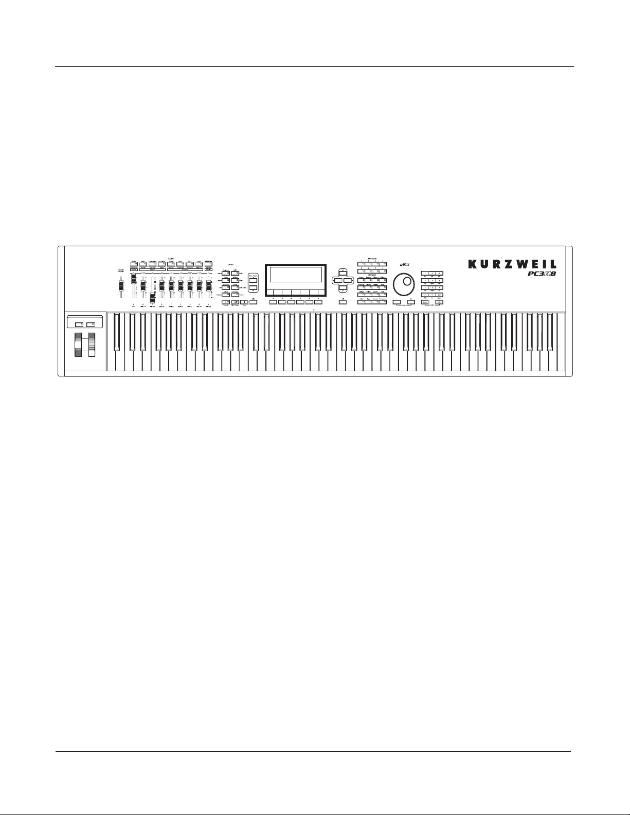
Overview of the PC3A
Pictured below is the 88-key PC3A8.
The PC3A’s 1400+ programs include improved piano sounds from the German D Grand EXP
expansion, and improved guitar, drums, synth, brass, and woodwind sounds from the KORE64
expansion. Also included are string sections from the Orchestral and Contemporary sound
blocks, Stereo Triple Strike Piano, Classic Keys for realistic vintage electric piano sounds, and
General MIDI (GM) sounds. Multi-zone performance setups are also provided; many of these
setups use note triggers to play factory-recorded songs that provide grooves and arpeggiation
that make great templates for performance or recording. An on-board sequencer with front panel
transport buttons lets you record your ideas any time inspiration strikes. This sequencer (Song
mode) lets you play back MIDI type 0 or 1 sequences, record and play back your own songs, and
record multi-timbral sequences received via MIDI.
In addition to V.A.S.T. capability, a few of the features that by themselves make the PC3A an
impressive stage and studio machine are:
• 128-voice polyphony
• Fully multi-timbral voices, so that dierent programs can be played on each MIDI channel.
• An on-board digital eects processor provides multiple simultaneous eects, including
real-time eects control, internally or via MIDI.
• More eects processing power than Kurzweil’s own KSP8 studio eects processor.
• Two additional balanced analog outputs in addition to the standard stereo audio output pair,
as well as a digital output. All of the outputs are available simultaneously.
For backup, storage, and moving les, two types of USB ports are provided on the back panel of
the PC3A. A USB storage port allows you to connect a USB device such as a thumb drive, and a
second USB Computer port lets you connect the PC3A to a computer for le transfer and MIDI
connectivity.
1-2
Page 21

Introduction
VA-1 Programs
VAST Synthesis
The PC3A’s Variable Architecture Synthesis Technology (V.A.S.T.) lets you build sounds from
realistic instrumental samples and sampled synth waveforms—then modify the nature of those
sounds through a wide variety of digital signal-processing (DSP) functions. The PC3A also
generates its own synth waveforms, which can be combined with the samples or used on their
own.
While many other synthesizers may oer a xed set of DSP tools (typically ltering, pitch, and
amplitude modulation) the PC3A’s Variable Architecture lets you arrange a combination of DSP
functions from a long list of choices. The functions you choose dene the type of synthesis you
use.
Each layer of every program has its own DSP architecture, which we call an algorithm. Within
each algorithm, you can select from a variety of DSP functions. Each function can be
independently controlled by a variety of sources including LFOs, ASRs, envelopes, a set of
unique programmable functions (FUNs), as well as any MIDI control message. The many
dierent DSP functions and the wealth of independent control sources give you an extremely
exible, truly vast collection of tools for sound creation and modication.
The PC3A oers powerful editing features we call Dynamic V.A.S.T. and Cascade Mode.
Dynamic V.A.S.T. allows you to “wire” your own algorithms, combining dierent DSP functions
in any order you like, including parallel and serial congurations.
Cascade Mode lets you route any layer of a program into the DSP of any other layer. Any of the 32
layers of a program can go into any other layer.
When you’re ready to jump in and start creating programs, turn to Chapter 6.
KB3 Tone Wheel Emulation
In addition to VAST synthesis, the PC3A oers many oscillator-based programs that give you the
classic sound of tone-wheel organs like the Hammond B3. KB3 mode, as we call it, is completely
independent of VAST, and has its own set of editing procedures. Nine dedicated sliders on the
PC3A’s front panel give you real-time drawbar control over these organ sounds. Buttons above
the sliders control rotating speaker speed, percussion, and other organ features.
The quickest way to get to the KB3 programs is by pressing the KB3 button (above the sliders, to
the left of the screen). The blue LED in the KB3 button will light when the current program is a
KB3 program.
VA-1 Programs
The VA-1 (Virtual Analog Synthesizer) programs included with the PC3A oer realistic
emulations of classic analog synthesizers, built from Kurzweil’s unique anti-aliased DSPgenerated oscillators. The PC3A’s power-shaped oscillators let you transition smoothly from one
waveform into another in real time, without using cross-fades.
VA-1 programs are scattered throughout the PC3A. Look for them in the Synth Category and the
Classic Keys Bank. You’ll see “KVA Oscillator” appear in the Keymap screen on the left hand side
of the display.
1-3
Page 22

Introduction
How to Use This Manual
This PC3A Musician’s Guide describes how to connect and power up your PC3A, and to hook up
the PC3A to your sound system and MIDI system. It provides an overview of the front panel,
and a brief description of the operating modes to help you start playing music with the
instrument. It covers the PC3A in its 88, 76, and 61-note congurations (PC3A8, PC3A7, and
PC3A6).
Detailed information on editing and advanced programming features is also provided on the
Kurzweil website:
http://www.kurzweil.com
The best way to read this guide is with your PC3A in front of you. By trying the examples we give
to illustrate various functions, you can get a quick understanding of the basics.
Do I Have Everything?
Your PC3A shipping carton should include the following in addition to your instrument:
• Power cable
• Sustain pedal
• USB cable
• Getting Started manual
If you don’t have all of these components, please call your Kurzweil/Young Chang dealer.
You may also want to purchase a USB thumb drive for portable backups and storage.
Boot Loader
When you need to update the PC3A’s software or run diagnostic tests, you’ll use the Boot Loader.
To bring up the Boot Loader, hold down the Exit button (below the cursor buttons, to the right of
the display) while powering on your PC3A. Refer to Appendix BAppendix B, p.1 for details on
the Boot Loader.
Battery
The PC3A uses a CR2032 battery to power its clock. The battery should last ve years, and a
message will tell you when the battery needs replacing. The access panel on the bottom of the
PC3A (which you can easily remove with a screwdriver) allows you to get at the battery for
removal and replacement.
CAUTION: Danger of explosion if battery is incorrectly replaced. Replace only with the same or
equivalent type (CR2032).
1-4
Page 23

Introduction
Options
Ask your Kurzweil dealer about the following PC3A options:
Sound ROM Expansion Card
The PC3A has the KORE64 and German D Grand EXP cards installed as standard components.
Pedals
The PC3A has jacks for three switch pedals (for functions like sustain or program/setup changes)
and two continuous pedals (for functions like volume control and wah). Your Kurzweil dealer
stocks the following optional pedals:
FS-1 Standard box-shaped switch pedal
KFP-1 Single piano-style switch pedal
KFP-2M Double piano-style switch pedal unit
CC-1 Continuous pedal
Ribbon Controller
There’s a dedicated modular jack (like a telephone jack) on the rear panel of the PC3A for
connecting this 600-mm (24-inch) ribbon controller. You can congure the PC3A to use the ribbon
as a single large controller, or a three-section controller with independent settings for each
section.
Breath Controller
You can plug a Yamaha (or equivalent) breath controller into the dedicated jack on the PC3A’s
rear panel.
USB Storage Device
You can plug a USB mass storage device such as a “thumb drive” or memory stick into the PC3A
for backing up, archiving, sharing your work, and updating your software. Any size USB mass
storage device will work, though thumb drives are recommended for their portability, durability,
and low price.
Note: Most USB thumb drives are compatible with the PC3A, but some older USB thumb drives and larger
USB bus powered drives will not work with the PC3A if they require more than 100 mA of current (high
power USB devices). When attempting to use an incompatible USB device, the PC3A will display the
message “USB device requires too much power.” The PC3A is designed to work with low power USB
devicesandcanprovideamaximumof100mAtoaUSBdevice.Powerrequirementspecicationsfor
thumb drives are not always made clearly available by the manufacturer, but a newly purchased thumb
drivewillmostlikelybecompatible.Ifpossible,checkthepowerrequirementspecicationsofyourUSB
device before purchase.
1-5
Page 24
Startup
Make Music
Chapter 2
Startup
If hooking up new gear is familiar to you, and you just want to get going, here’s a quick
description of what you need to get started with your PC3A. If you need more information,
thorough descriptions of each step follow.
Make Connections
1. Set the keyboard on a hard, at, level surface. Make sure to leave plenty of room for
ventilation.
2. Four adhesive-backed rubber feet are provided with your PC3A. If you want to attach them
to the bottom of the PC3A(recommended to prevent scratching your tabletop), carefully
turn the keyboard over, remove the paper backing from the rubber feet and attach them
now, near each corner, all on the same level.
3. Connect the power cable.
4. Make sure your sound system is at a safe volume level. Also make sure that the PC3A’s
5. Plug in a pair of stereo headphones or run standard (1/4-inch) audio cables from your
Make Music
6. Power up your PC3A, raise the level of the MASTER VOLUME slider, and check out some of
MASTER VOLUME slider (on the far left side of the front panel) is all the way down.
amplier or mixer to the MIX audio outputs on the PC3A. (Use the Main Left out for
mono.) Balanced (“TRS” or “Stereo”) cables are recommended.
the programs and setups. The PC3A starts up in Program mode by default. Press one of the
mode buttons to the left of the display to switch modes.
7. If you hear distortion, reduce the gain on your mixing board, or use the pad if it has one.
8. Scroll through the program list with the Alpha Wheel, or the dedicated Category and
Program buttons, and try the PC3A’s many sounds.
2-1
Page 25
Startup
Startup—the Details
Startup—the Details
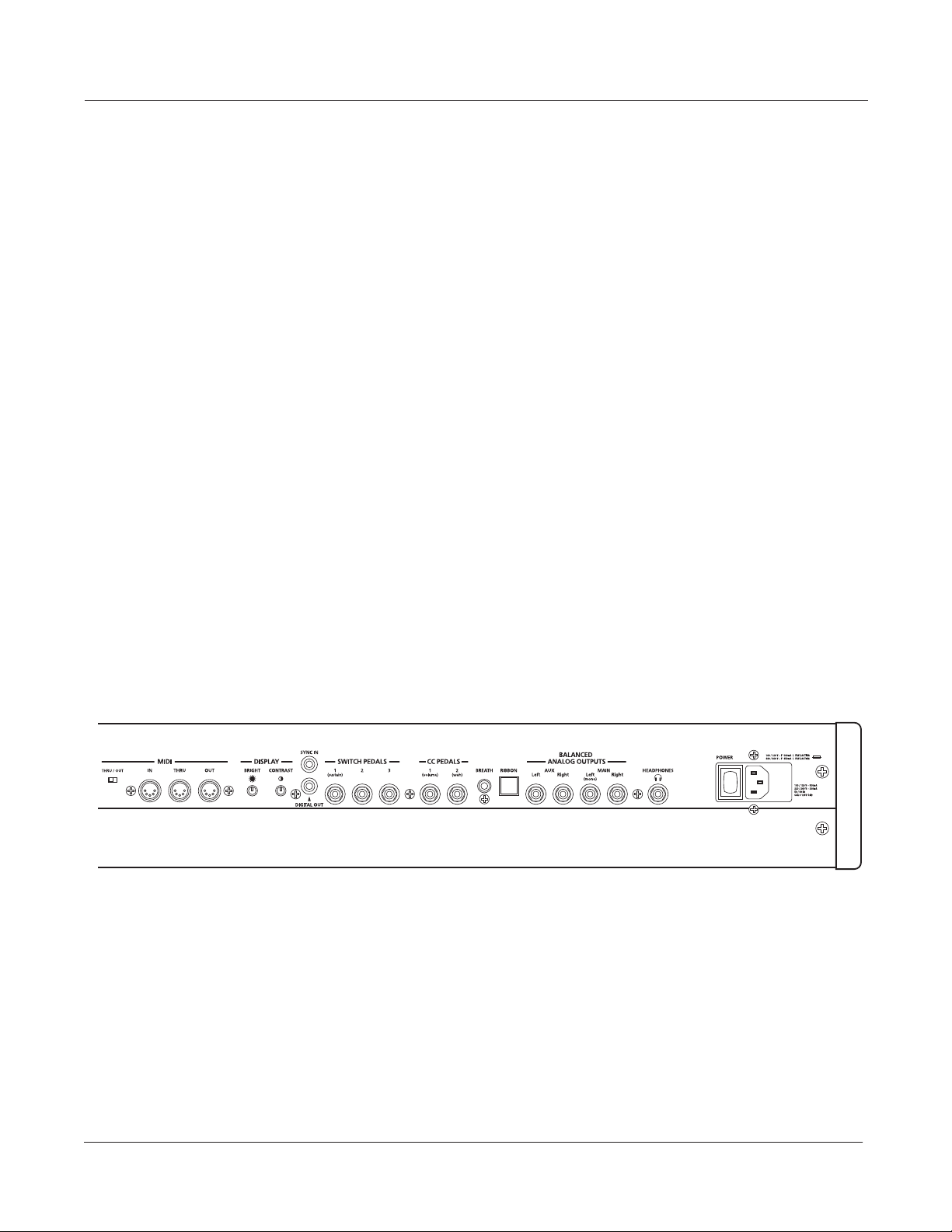
This section walks you through the hookup of your PC3A. We’ll take a look at the rear panel, then
describe the power, audio, and other cable connections.
Before You Start...
Don’t connect anything until you make sure your PC3A is properly and safely situated. Also, if
your PC3A has been out in the cold, give it time to warm up to room temperature before starting
it, since condensation may have formed inside the PC3A. It is normal for the rear panel near the
MIDI jacks to become warm after a while.
Connecting the Power Cable (Line Cord)
The PC3A runs on AC power: 100, 120, 230, or 240 volts at 50–60 Hz. Your dealer will set the
voltage switch to match the voltage in your area. The voltage level is set with a selector on the
rear panel of the PC3A. Unless you are sure it needs to be changed, you shouldn’t adjust this.
When you’ve connected the cable at the PC3A end (as you face the back of the PC3A, the power
connection is at the right), plug it into a grounded outlet. If your power source does not have the
standard three-hole outlet, you should take the time to install a proper grounding system. This
will reduce the risk of a shock.
2-2
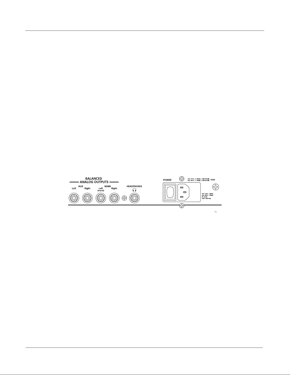
Connecting Audio Cables
Analog
After you’ve turned down the level on your sound system, connect the PC3A’s analog audio
outputs to your sound system using a pair of stereo or mono audio cables. Mono cables will
always work, but if you’re going into balanced inputs, use stereo cables for a better signal-tonoise ratio and a bit more volume. The PC3A’s analog outputs are balanced, and generate a
“hotter” signal than some previous Kurzweil instruments.
You’ll nd four 1/4-inch balanced audio output jacks on the rear panel. For now, connect one end
of each audio cable to your mixing board or PA system inputs, and connect the other end to the
jacks marked Main Left and Right on the rear panel of the PC3A. If you have only one input
available, use the PC3A’s Main Left output to get the full signal in mono.
In Master mode you can set the Aux outputs to duplicate the Main Outs – useful for monitoring
and other operations. They are always in stereo, as is the headphone out.
Page 26
Startup
Startup—the Details
Digital
For digital audio output from the PC3A, connect a 75-Ohm coaxial cable from the PC3A’s RCA
Digital Out jack to the AES or S/PDIF input of the receiving device. You may need an RCA-to-
XLR adapter to connect with the receiving device. If the receiving device receives only optical
signals, you’ll need a converter as well. The PC3A’s Master Page (press the Master mode button)
lets you select a range of useful sample rates for the digital output.
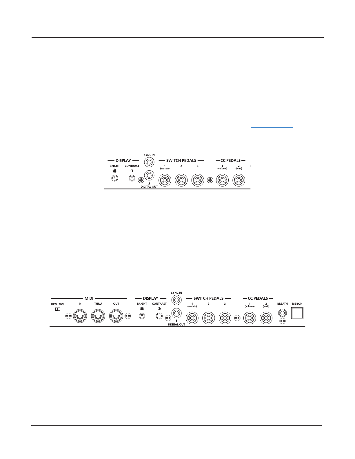
The RCA jack labeled “Sync In” allows you to synchronize the PC3A’s S/PDIF Digital Audio
output sample rate to an external S/PDIF source. Although no audio signal is received by the
“Sync In” jack, its clock is received and may be used to set the output sample rate. For details, see
the Master Mode OUTPUT page parameter Digital Output (Dig. Out) in Ch. 11, page 10. NOTE:
Sync In is NOT a “Word Clock” input. Only a valid S/PDIF signal is recognized.
Connecting MIDI
The simplest MIDI conguration uses a single 5-pin MIDI cable: either from the MIDI Out port of
your PC3A to the MIDI In port of another instrument, or from the MIDI Out port of another MIDI
controller to the MIDI In port of the PC3A. There are all sorts of possible congurations,
including additional synths, personal computers, MIDI eects processors, and MIDI patch bays.
Depending on your system, you may want to use the PC3A’s MIDI Thru port to pass MIDI
information from a MIDI controller to the PC3A and on to the next device in your system. You
can also connect MIDI devices to the PC3A’s MIDI Out port, which can send channelized MIDI
information from the keyboard or through the PC3A from your MIDI controller.
The MIDI Thru port can be congured to serve as an additional MIDI Out by sliding the nearby
switch to the Out position.
You can also use the PC3A’s USB port to send and receive MIDI. By default the PC3A will show
up as a USB MIDI device. If you choose USB Temporary Drive from Storage mode, the PC3A will
temporarily (while on that Storage mode page) become a “virtual storage device” and USB MIDI
will be disabled. Dierent host programs on your computer may indicate various errors as the
USB MIDI device is no longer present. Leaving Storage mode will restore USB MIDI
functionality.
USB MIDI and 5-pin MIDI can be used at the same time; the MIDI signals will be combined into a
single 16-channel MIDI stream.
2-3
Page 27

Startup
Startup—the Details
Pedals
Plug your switch or continuous pedals into the corresponding jacks on the PC3A’s rear panel. We
recommend using the Kurzweil pedals described on page 1-5, but you can use almost any switch
or continuous pedal, as long as it adheres to the following specications (as most pedals do):
Breath
Switch pedals
Continuous pedals 10-kOhm linear-taper potentiometer,
1
/
-inch tip-sleeve plug
4
1
/
-inch tip-ring-sleeve plug
4
with the wiper connected to the tip.
If you use a third-party (non-Kurzweil) switch pedal, make sure it’s connected before you turn
on your PC3A. This ensures that the pedal will work properly (it might function backward—o
when it’s down and on when it’s up—if you turn on your PC3A before plugging in the pedal).
Similarly, don’t press any of your switch pedals while powering up, because the PC3A veries
each pedal’s orientation during power up. If you’re pressing a pedal, you might cause it to work
backward.
The pedals are independently programmable within each zone of every setup. Here are the
default settings for the ve pedals you can use with the PC3A:
Switch Pedal 1 Controller 64 (Sustain)
Switch Pedal 2 Controller 66 (Sostenuto)
Switch Pedal 3 Controller 67 (Soft)
Continuous Control Pedal 1 Controller 11 (Expression / Volume)
Continuous Control Pedal 2 Controller 4 (Foot Pedal) producesa“wah”eectinmanysetups
The 3.5mm jack labeled Breath accepts a standard breath controller, which sends standard MIDI
Breath (MIDI 2) messages. The PC3A’s preset programs and setups don’t respond to breath, but if
you have other instruments that do respond to Breath, you can control them from the PC3A via
MIDI.
2-4
You can also program the PC3A so that the breath controller sends a dierent MIDI message. This
would enable you to use a breath controller to aect the PC3A, but then other instruments
receiving MIDI from the PC3A would no longer respond to the PC3A’s breath controller (unless
you also programmed them to receive the same MIDI Controller that the PC3A’s breath
controller is sending).
Page 28
Startup
Startup—the Details
Ribbon
Plug the optional Kurzweil Ribbon Controller into the modular Ribbon jack on the rear panel.
The ribbon controller itself should rest on a at surface; it ts nicely between the keys and the
buttons and sliders on the front panel.
The ribbon is a continuous controller. You can program the ribbon controller to send MIDI
Controller messages 1–127, as well as several specialized messages. It generates values of 0–127
for whatever MIDI Controllers you assign it to send. Just press it, and slide your nger along the
ribbon to change the value of the message it’s sending.
You can congure the ribbon to have one control section that runs its entire length, or to have
three sections of equal length. It sends its highest values when you press it at the end where the
cable connects. When you congure it to have three sections, each section sends its highest values
at the end closest to the cable.
Caution: The modular jack is designed for connection to the Kurzweil Ribbon Controller option only.
Don’t plug any other modular plugs into the Ribbon jack.
Switching On the Power
The PC3A’s power switch is on the rear panel, adjacent to the power cable connection.
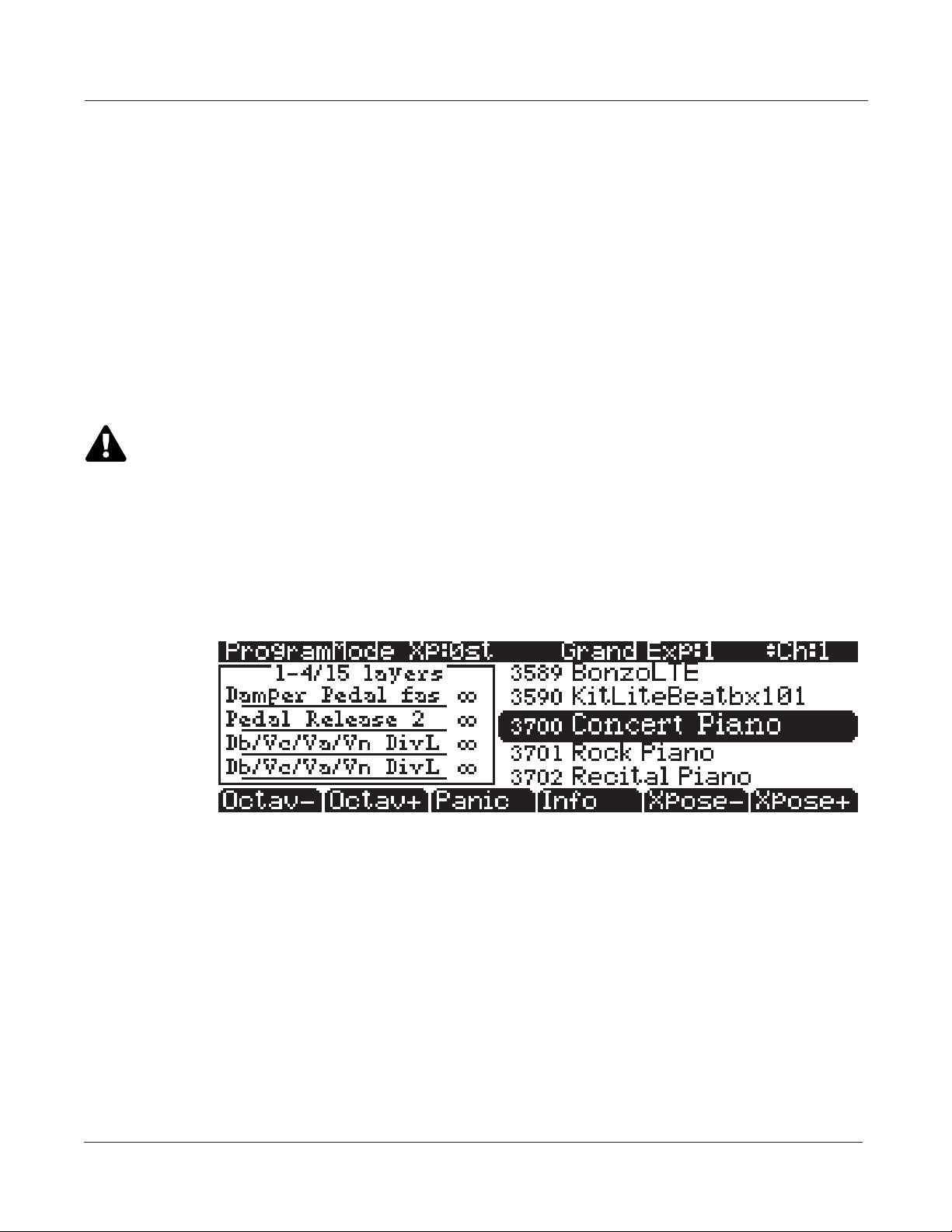
When you power up, the display briey shows some startup information. The Program mode
display then appears. It looks like the diagram below, though your PC3A may be dierent from
the example.
The rst time you power up (or after a reset), your instrument will be set to operate on MIDI
Channel 1 (as shown at the far right of the top line above).
Set the volume at a comfortable level. You’ll get the best signal-to-noise ratio if you keep the
PC3A at full volume, and adjust the level from your mixing board. You may also want to adjust
the display contrast and brightness. There are two small knobs on the rear panel of the PC3A for
this purpose.
2-5
Page 29
Startup
Startup—the Details
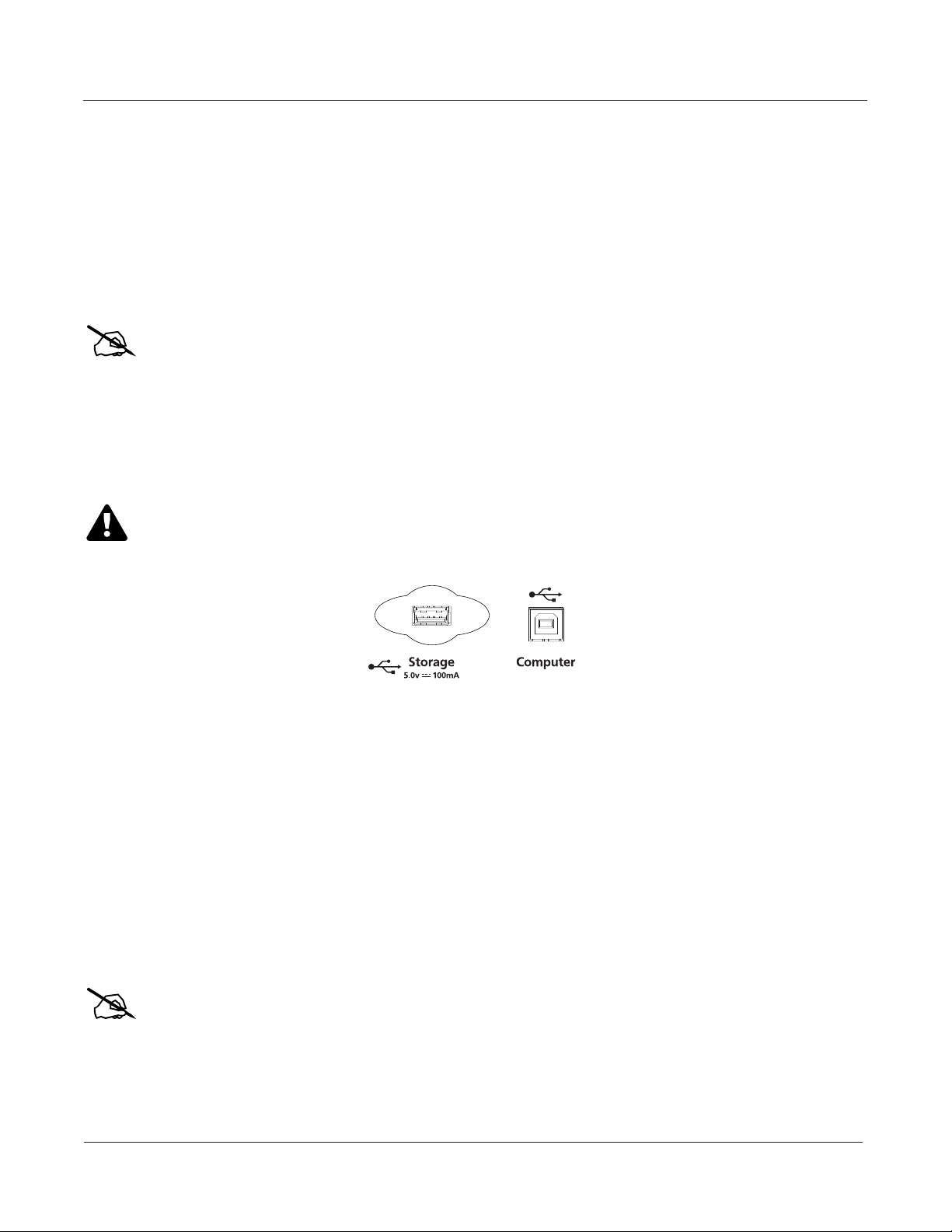
USB Storage Port
Note: Most USB thumb drives are compatible with the PC3A, but some older USB thumb drives and
Caution: Do not remove a USB device while the display says Loading... or Saving.... Removing a USB
You can plug a USB mass storage device such as a “thumb drive” into the PC3A for backing up,
archiving, sharing your work, and updating your software. Any size USB mass storage device
will work, though thumb drives are recommended for their portability, durability, and low price.
The USB Storage port is on the back panel of the PC3A, but it is easily accessible from the front of
the instrument. A USB connector will only t into the port if oriented properly, so don’t force it
into the port, as this may damage your PC3A or USB device. If you are having trouble inserting
your USB connector into the port, try ipping the connector over.
larger USB bus powered drives will not work with the PC3A if they require more than 100 mA of current
(high power USB devices.) When attempting to use an incompatible USB device, the PC3A will display the
message “USB device requires too much power”. The PC3A is designed to work with low power USB
devicesandcanprovideamaximumof100mAtoaUSBdevice.Powerrequirementspecicationsfor
thumb drives are not always made clearly available by the manufacturer, but a newly purchased thumb
drivewillmostlikelybecompatible.Ifpossible,checkthepowerrequirementspecicationsofyourUSB
device before purchase.
deviceduringaletransfercancausedatacorruption.
2-6
USB Computer Port
Next to the USB Storage port on the back panel of the PC3A is a USB Computer port. The USB
Computer port works for MIDI (transmit and receive) or to connect your PC3A to a computer for
le transfer. By default, the USB port is set to MIDI mode. When selecting USB PC connection in
Storage mode, USB MIDI will temporarily be disabled.
We recommend that you use the USB cable provided with your PC3A and do not use extension
USB cables. The PC3A’s USB Computer port is only intended for connection to a USB Type A
port.
In USB Storage mode, a “PC3A” virtual drive will appear on your computer desktop. One
important thing to know here is that this is a virtual drive. You can save to this drive from the
PC3A, but you must immediately transfer that le to your desktop (or other folder). You must
copy data from the PC3A virtual drive to your computer’s drive or else the data will be lost.
Note: When transferring les to and from the PC3A via the USB Computer Port, the maximum
size of les that can be transferred is approximately 1.6MB. This is suitable for most objects.
When using the USB Storage Port to transfer les, the le size that can be transferred is limited
only by the size of the USB mass storage device and the PC3A’s available object memory.
Page 30

Startup
PC3A Programs
When you leave Storage Mode, there will be a prompt telling you that the PC3A is turning back
into a USB MIDI device - which you have to acknowledge. If you haven’t copied the le(s) to
your desktop (or other place on the computer) it won’t be on the virtual disk when you leave
storage mode.
Depending on your computer’s operating system, you may sometimes see a scary device
removal warning on your desktop (for example, when the PC3A leaves the Boot Loader). You
may disregard such a message without worries of damage to your PC3A or computer.
Setting the Clock
The rst time you start up your PC3A is probably a good time to set the instrument’s clock to
your current local time. Do this from the Master mode CLOCK page.
The clock will time-stamp your les that have been stored via USB.
PC3A Programs
The PC3A powers up in Program mode, where you can select and play programs (called patches,
presets, or voices on other instruments). Programs are preset sounds composed of up to 32 layers
of samples or waveforms. If you’ve left Program mode, just press the Program mode button or
Exit button to return.
Selecting Programs
When you are in Program mode, there are three basic ways to select a PC3A program:
• Press one of the Bank buttons (above the sliders on the left side of the front panel) to select a
bank, then press a Category button and a Program button. The Category and Program
buttons are on the front panel, between the screen and the alpha wheel. Note: The instrument
names above the Category buttons are relevant for Banks 1 and 2 (Base 1 and Base 2). For all other
Banks, the Category buttons select a group of 8 programs to be selected by the Program buttons, but
the group of programs may not match the instrument name of the selected Category button. (See
Program and Category Buttons in Ch. 3, page 4 for more details.)
• Type the program’s ID (number) on the alphanumeric buttonpad, then press Enter. If you
make a mistake, press Clear, then start over.
• Scroll through the list using the Alpha Wheel, the Plus or Minus button under the Alpha
Wheel, or the cursor buttons (the arrow buttons to the right of the display).
The PC3A has various settings for responding to MIDI Program Change commands from
external sources. These are explained in Chapter10 , so we won’t go into them here. You should
be able to change programs by sending Program Change commands from your MIDI controller.
Easy Audition
Any time you want to hear what a program sounds like, highlight the program’s name (while in
Program mode) then press the Play/Pause button to play a brief sample. The Demo Button
parameter on the Master Mode MAIN page must be on for Easy Audition to work; the parameter
is on by default. Master mode is described in Chapter 11.
2-7
Page 31

Startup
PC3A Programs
Program Mode Display
Take a minute to familiarize yourself with the Program mode display. It gives you some helpful
basic information, like the MIDI transposition, what MIDI channel you’re on, and which
program is currently selected.
Info Box
There’s a box at the left side of the display. The info box, as it’s called, displays information about
the current program (there’s also an info box for Setup mode).
Soft buttons
On most PC3A screens, the bottom line of the display identies the function of each of the
buttons beneath the display. We call these buttons soft buttons, because they do dierent things
depending on what’s currently showing in the display.
In Program and Quick Access modes, you can change octaves with the Octav- and Octav+
buttons under the display. The Info soft button shows you relevant details about the current
item. The Xpose-/Xpose+ buttons are a shortcut for quick transposition in semitone (half step)
increments. You can use them to transpose the entire PC3A as much as three octaves up or down.
The top line of the display shows the current amount of transposition (Xpose). Press both Xpose
buttons simultaneously to return transposition to zero.
The Panic button (or a double press of Cancel and Enter at the bottom of the alphanumeric
keypad) sends an All Notes O message and an All Controllers O message—both to the PC3A
and over all 16 MIDI channels. You won’t need it often, but it’s nice to have.
VAST Programs
A “normal” VAST program is what most of the factory programs are. The info box contains
details about the dierent layers in each program, usually indicating the keymap used in each
layer. The line under the keymap name indicates the layer’s keyboard range. In this case, only the
rst two displayed layers extend across the entire keyboard (A 0 to C 8). The × symbol to the right
of each layer shows that the keymap is a stereo keymap.
2-8
Page 32

Startup
Quick Access
KB3 Programs
KB3 (organ) programs dier from VAST programs in that they don’t have layers. Instead they
rely on oscillators that mimic the tone wheels used in many popular organs. Consequently, the
info box shows only the waveform used in the program. Because of their architecture, KB3
programs require dierent processing within the PC3A. KB3 programs play only on a single
channel at a time (VAST programs will work ne on that channel, too).
The quickest way to get to the KB3 programs is by pressing the KB3 button that’s above the
sliders.
When you’re ready to start doing your own programming, check out Chapter 6 .
Setups
Setups are preset combinations of programs. Setups can have up to 16 zones, each of which can
be assigned to any range of the keyboard (overlapping or split). Each zone can have its own
program, MIDI channel, and MIDI control assignments, as well as ri and arpeggiator settings.
Press the Setup mode button to the left of the display. Its LED will light, telling you that you’re in
Setup mode. Notice that the Setup mode display is similar to the Program mode display. If the
setup has four or fewer zones, the box at the left shows you the programs assigned to each of the
setup’s zones. If the setup is composed of more than four zones, then the box displays the rst
four zones; at the top of the box will be text showing the total number of zones. See Ch. 7, page 1
for a more detailed description.
Many setups include arpeggiation and note-triggered songs to create some pretty amazing
grooves that you can use as is, or as templates for your own material. As you play with these
setups, experiment with the sliders and other controllers for a wide range of eects. Some of
these grooves keep playing after you’ve released the keys that got them going. When you want to
stop them, select another setup, or press the Setup mode button (or Stop for ris).
Quick Access
A really convenient way to select programs and setups is to use Quick Access mode, where you
select a Quick Access bank from a list of factory preset or user-programmed banks. Each bank
contains ten memory slots, or entries, where you can store any combination of programs or
setups. While you’re in Quick Access mode, you can select any program or setup in the bank with
buttons 0 through 9 or the cursor keys.
The PC3A comes with a few Quick Access banks already programmed so you can get an idea of
how they work. You’ll probably create your own Quick Access banks to help you select programs
and setups with a minimum of searching. Press the Quick Access mode button to the left of the
display. Its LED lights, to tell you you’re in Quick Access mode.
2-9
Page 33

Startup
Software Upgrades
The top line of the display tells you which Quick Access bank is selected. Use the Chan/Layer
buttons (to the left of the display) to scroll through the banks. The names of each of the ten entries
in the bank are listed in the center of the display. Many of their names will be abbreviated. The
currently selected entry’s full name is shown near the bottom of the display. The amount of
transposition is displayed to the left of the entry name. If the current entry is a program, you’ll
see the current keyboard (MIDI) channel displayed to the right of the entry’s name. If it’s a setup,
you’ll see the word Setup.
The entries on the Quick Access page are arranged to correspond to the layout of the numeric
buttons on the alphanumeric pad.
When you’re ready to create your own Quick Access banks, turn to Chapter8 to learn about the
Quick Access Editor.
The Other Modes
There are ve other mode buttons on the front panel. See Chapters 3 and 4 for more detailed
descriptions of the modes.
Eects mode Enable/disable eects presets, and set Aux overrides.
MIDI mode Congure the PC3A for sending and receiving MIDI information.
Master mode Dene performance and control settings.
Song mode Record and edit sequences (songs); play Type 0 and Type 1 MIDI
Storage mode Load and save programs, setups, sequences, and other objects via USB
Software Upgrades
It’s easy to upgrade the PC3A’s operating system and objects (programs, setup, etc.) using the
boot loader to install upgrades into ash ROM. When upgrades are available you can download
them from www.kurzweil.com and install them via one of the PC3A’s two USB ports.
When you’ve downloaded an upgrade, you can install it yourself in a matter of minutes. Follow
the instructions included with the upgrade les.
sequences.
device.
2-10
Page 34

User Interface Basics
Arp
SW
Mode Selection
Chapter 3
User Interface Basics
This chapter will show you how to get around the front panel of your PC3A. Your interactions
can be divided into three primary operations: mode selection, navigation, and data entry. There
is also an assignable control section.
Mode Selection
The PC3A is always in one of eight primary operating modes. Select a mode by pressing one of
the mode buttons — they’re to the left of the display. Each mode button has an LED that lights to
indicate the current mode. Only one mode can be selected at a time.
Program mode Select and play programs, and modify them with the Program Editor.
Setup mode Select and play setups (16 keyboard zones with independent MIDI
channel, program and control assignments), and modify them with the
Setup Editor.
Quick Access mode Select from a list of preset banks, each containing a list of ten programs
and/or setups that can be viewed in the display for easy selection. Modify
the preset banks and create your own with the Quick Access Editor.
Eect mode Enable/disable eects or set Aux overrides for Program Mode (or a
program selected from Quick Access mode.)
MIDI mode Dene how your PC3A sends and receives MIDI information, and
congure each channel to receive independent program, volume, and pan
messages that override the normal Program mode settings.
Master mode Dene performance and control characteristics for the entire PC3A.
3-1
Page 35

User Interface Basics
Bank Buttons
Song mode Use the PC3A’s sequencer to record and play back your keyboard
Storage mode Interface with the PC3A’s USB storage or computer ports to load and save
The PC3A’s tone wheel organ emulation is called KB3 mode. You automatically enter this mode
when you select a KB3 program. The KB3 Bank button takes you there directly.
Mode Buttons
performance, play Type 0 and Type 1 MIDI sequences, and record multitimbral sequences received via MIDI.
programs, setups, samples, and more.
When you press a mode button, its LED lights up to indicate that the mode has been selected. If
pressing a mode button does not light its LED, press the Exit button one or more times, then try
again.
Additional labeling for each mode button indicates special functions that relate to some of the
PC3A’s editors.
Bank Buttons
The Bank buttons, situated in the top left corner of the PC3A’s front panel, let you choose
dierent banks of programs (e.g., KB3 programs or Classic Keys programs). Within each bank,
you can use the Program and Category buttons (to the right of the display) to select individual
programs.
The Bank buttons have special functions in KB3 mode, indicated by labels beneath each button.
3-2
Page 36

User Interface Basics
Bank Buttons
Sliders
In KB3 mode, the PC3A’s nine sliders emulate an organ’s drawbars. For example, slider A
emulates an organ’s 16’ drawbar. In other modes, the sliders can be used to send values for
dierent MIDI controllers. In either case, you may have to move the slider past the current value
for its selected function before slider movement will have any eect. Press the Info soft button on
the Program mode or Setup mode main page to see the slider assignments of the current program
or setup.
Most VAST programs use the sliders for these functions:
A Data Filter frequency, Brightness
B MIDI 13 Filter resonance, Tremolo rate control
C MIDI 22 Layer volume, Envelope control, Lo EQ
D MIDI 23 Layer volume, Envelope control, Hi EQ
E MIDI 24 Layer volume for thumps and release
F MIDI 25 FX control 1
G MIDI 26 FX distortion drive
H MIDI 27 FX distortion warmth
I MIDI 28 Reverb / delay control
3-3
Page 37

User Interface Basics
Program and Category Buttons
Program and Category Buttons
Use the Program and Category buttons, in conjunction with the Bank buttons, to select PC3A
programs by Bank type and instrument category. Each Bank contains 128 programs divided into
16 categories. Each of the 16 categories contains 8 programs.
To select a program, rst press one of the Bank buttons (above the sliders on the left side of the
front panel) to select a bank, then press a Category button and a Program button. The Category
and Program buttons are on the front panel, between the screen and the alpha wheel.
Note: The instrument names above the Category buttons are relevant for Banks 1 and 2 (Base 1 and Base
2). For all other Banks, the Category buttons select a group of 8 programs to be selected by the Program
buttons, but the group of programs may not match the instrument name of the selected Category button.
3-4
Picking favorites
When you select a program within a category, your selection will be remembered. For example,
choose program 3 in the Organ category (press Category: Organ, then Program: 3). Now move to
the strings by pressing the Category: Strings button. If you press the Category: Organ button
again, you will be returned to program 3 in the Organ category. In this way, each category can
have a “favorite” program.
You can make program selections within each category ahead of time. This way, you’ll be able to
access the program you want in any category simply by pressing appropriate category button.
Important things to remember about your “favorites”:
• You must save your PC3A’s Master Table to remember your selections across power cycles.
See Chapter11 for information about the Master Table.
• Your selections are bank-dependent. In other words, you can save 16 in the Base 1 bank, 16 in
the Exp 1 bank, etc.
Page 38

User Interface Basics
Pitch Wheel and Mod Wheel
Pitch Wheel and Mod Wheel
Arp
SW
Pitch Mod
To the left of the PC3A’s keyboard are the Pitch Wheel and the Mod Wheel, as well as the SW and
Arp buttons.
Push the Pitch Wheel away from you to raise the pitch of the note(s) you are playing. Pull it
towards you to lower the pitch. Most programs are set so that the pitch wheel will raise and
lower pitch by a whole step, although some programs use the pitch wheel to lower pitch by as
much as an octave. The Pitch Wheel has a spring so that it will snap back to place (i.e., back to the
original pitch) when you release it.
The Mod Wheel performs a variety of functions. Dierent programs may use it for lter sweeps,
tremolo/vibrato, wah, or layer volume.
The Arp button turns on and o the PC3A’s Arpeggiator.
The SW button (MIDI 29) can be programmed to do a variety of things. Often it is used for layer
enable or eect enable.
3-5
Page 39

User Interface Basics
Navigation
Navigation
The navigation section of the front panel consists of the display and the buttons surrounding it.
These navigation buttons will take you to every one of the PC3A’s programming parameters.
The Display
Your primary interface with the PC3A is its backlit graphic display. As you press various buttons,
this uorescent display reects the commands you enter and the editing changes you make. The
ample size of the display (240-by-64 pixels) enables you to view lots of information at one time.
Pages
Within each mode, the functions and parameters are organized into smaller, related groups that
appear together in the display. Each one of these groups of parameters is called a page. Each
mode has what we call an entry-level page; it’s the page that appears when you select that mode
with one of the mode buttons. Within each mode and its editor(s), the various pages are selected
with the navigation buttons. There are many pages, but there are a few features common to each
page.
The illustration below shows the entry-level page for Program mode.
3-6
The Top Line
On the top line of most pages, there’s a reminder of which mode you’re in and which page you’re
on. Many pages display additional information in the top line, as well. The Program-mode page
above, for example, shows you the current amount of MIDI transposition and the currently
selected MIDI channel. The top line is almost always “reversed”—that is, it has a white
background with blue characters.
The Bottom Line
The bottom line is divided into six (sometimes fewer) sets of reversed characters that serve as
labels for the six buttons directly beneath the display. These labels—and the functions of the
buttons—change depending on the currently selected page. Consequently the buttons that select
these functions are called “soft” buttons.
Page 40

User Interface Basics
Navigation
The Soft Buttons
The soft buttons are called “soft” because their functions change depending on the currently
selected mode and page. Sometimes they perform specic functions, like changing MIDI
channels in Program mode. In the Program Editor and other editors, they’re also used to move to
dierent pages of programming parameters. If a soft button’s label is in all capital letters
(KEYMAP, for example), pressing the corresponding soft button takes you to a page of
parameters. If the soft button is labeled in lower-case or mixed-case letters (Save, for example),
the soft button performs some kind of function.
The Cursor Buttons
To the right of the display are four buttons arranged in a diamond fashion. These are called the
cursor buttons. They move the cursor around the currently selected page, in the direction
indicated by their labels. The cursor is a highlighted (reversed) rectangle (sometimes it’s an
underscore). It marks the value of the currently selected parameter.
Programming the PC3A involves selecting various parameters and changing their values. Select
parameters by highlighting their values with the cursor. You can change the highlighted value
with any of the data entry methods described in the data entry section below.
The Chan/Layer Buttons
To the left of the display are two buttons labeled Chan/Layer. Their function depends on the
current mode. In Program mode, for example, they shift through the MIDI channels, showing the
program assigned to each channel. This changes the MIDI channel the PC3A uses internally, as
well as the channel you’re using to send information to other synths connected to the PC3A’s
MIDI Out port (MIDI slaves). Changing the current MIDI channel also changes the
corresponding setting on the MIDI mode TRANSMIT page. When you press both Chan/Layer
buttons at the same time you will be returned to Channel 1, Check out the chart on page 3-10 for
more shortcuts you can make with double button presses.
When you’re in the Program Editor, the Chan/Layer buttons let you view each layer in the
program. You can see the corresponding parameters in each layer by scrolling through the layers
with these buttons. In the Setup Editor, the Chan/Layer buttons scroll through the zones in the
current setup. In Quick Access mode, they scroll through the Quick Access banks, and in Song
mode they scroll through recording tracks.
3-7
Page 41

User Interface Basics
Navigation
The Edit Button
The Edit button activates each of the PC3A’s editors, and acts as a shortcut to many pages within
the Program Editor. Pressing the Edit button tells the PC3A that you want to change some aspect
of the object marked by the cursor. For example, when a program is selected and you press Edit,
you enter the Program Editor. If a setup is selected, you enter the Setup Editor.
There are editors accessible from just about every operating mode. To enter an editor, choose one
of the modes (mode selection), and press Edit. An editing page for that mode will appear. You
can then select parameters (navigation) and change their values (data entry). If the value of the
selected parameter has its own editing page, pressing the Edit button will take you to that page.
For example, in the Program Editor, on the PITCH page, you might see LFO1 assigned as the
value for Pitch Control Source 1. If you select this parameter (the cursor will highlight its value—
LFO1 in this case), then press the Edit button, you’ll jump to the page where you can edit the
parameters of LFO1. Naturally, you can nd every page in the current editor by using the soft
buttons, but often it’s easier to use the Edit button shortcut.
The Exit Button
Press Exit to leave the current editor. If you’ve changed the value of any parameter while in that
editor, the PC3A will ask you whether you want to save your changes before you can leave the
editor. See Chapter 5 for information on saving and naming. The Exit button also takes you to
Program mode if you’re on the entry level page of one of the other modes. If at some point you
can’t seem to get where you want to go, press Exit one or more times to return to Program mode,
then try again.
3-8
Page 42

User Interface Basics
Navigation
Data Entry
The data entry section of the front panel includes the Alpha wheel, the Plus/Minus buttons, and
the 14-button alphanumeric pad.
The Alpha Wheel
The Alpha Wheel is especially useful because it can quickly enter large or small changes in value.
If you turn the Alpha Wheel one click to the right, you’ll increase the value of the currently
selected parameter by one increment. One click to the left decreases the value by one increment.
If you turn it rapidly, you’ll jump by several increments. You can also use the Alpha Wheel to
enter names when you’re saving objects.
The Plus/Minus Buttons
These buttons are located just under the Alpha Wheel. The Plus button increases the value of the
currently selected parameter by one, and the Minus button decreases it by one. These buttons are
most useful when you’re scrolling through a short list of values, or when you want to be sure
you’re changing the value by one increment at a time. One press of the Plus or Minus button
corresponds to one click to the right or left with the Alpha Wheel. These buttons will repeat if
pressed and held.
Pressing the Plus and Minus buttons simultaneously will move you through the current list of
values in large chunks instead of one by one. Don’t confuse these buttons with the +/- button on
the alphanumeric pad. This button is used primarily for entering negative numeric values and
switching from uppercase to lowercase letters (and vice versa).
The Alphanumeric Pad
As its name implies, this set of 14 buttons lets you enter numeric values, and to enter names one
character at a time. Depending on where you are, the PC3A automatically enters letters or
numerals as appropriate (you don’t have to select between alphabetic or numeric entry).
When you’re entering numeric values, press the corresponding numeric buttons, ignoring
decimal places if any (to enter 1.16, for example, press 1, 1, 6, Enter). The display will reect your
entries, but the value won’t actually change until you press Enter. Before pressing Enter, you can
return to the original value by pressing Cancel. Pressing Clear is the same as pressing 0 without
pressing Enter.
When entering names, you can use the Left/Right cursor buttons or the <<< / >>> soft buttons to
move the cursor to the character you want to change. Use the labels under the alphanumeric
buttons as a guide to character entry. Press the corresponding button one or more times to insert
the desired character above the cursor. The Cancel button is equivalent to the >>> soft button,
and Enter is the same as OK. The Clear button replaces the currently selected character with a
space. The +/- button toggles between uppercase and lowercase letters.
There’s also a convenient feature called keyboard naming, which lets you use the keyboard to
enter characters in names. See page 5-5.
3-9
Page 43

User Interface Basics
Navigation
Double Button Presses
Pressing two or more related buttons simultaneously executes a number of special functions
depending on the currently selected mode. Make sure to press them at exactly the same time.
In this mode
or editor…
Program mode
Setup mode
Song mode
Storage mode
Program Editor
Any Editor
Save Dialog
Rename Dialog
…pressing these
buttons
…does this:
simultaneously…
ARP, SW Brings up quick arpeggiator conguration page.
Octav-, Octav+ Reset MIDI transposition to 0 semitones. Double-press again to go
to previous transposition.
Chan/Layer Set current MIDI channel to 1. Sets layer 1 in Program editor.
Plus/Minus Step to next Program bank (increments of 128).
Up/Down cursor buttons Starts playback of demo song for current Program. Stop with Stop
transport button.
Left/Right cursor buttons Brings up the TEMPO page.
Plus/Minus Moves through list of Setups in increments of 128.
Chan/Layer Set zone 1.
Left/Right cursor buttons Brings up the TEMPO page.
Up/Down cursor buttons Toggle between Play and Stop.
Chan/Layer Select all tracks on any TRACK page in Song Editor.
Left/Right cursor buttons Brings up the TEMPO page.
Left/Right cursor buttons Select all items in a list. Move cursor to end of name in naming
dialog.
up/down cursor buttons Clear all selections in a list. Move cursor to beginning of name in
naming dialog.
Chan/Layer Select Layer 1.
Plus/Minus Scroll through the currently selected parameter’s list of values in
regular or logical increments (varies with each parameter).
2 leftmost soft buttons Reset MIDI transposition to 0 semitones. Double-press again to go
to previous transposition.
Center soft buttons Select Utilities menu.
2 rightmost soft buttons Reset MIDI transposition to 0 semitones. Double-press again to go
to previous transposition.
Left/Right cursor buttons Display the TEMPO page.
Up/Down cursor buttons Toggle between Play and Stop of current song.
Cancel/Enter Panic (sends all notes/controllers off message on all 16 channels).
Plus/Minus buttons Toggle between next free ID and original ID.
Plus/Minus buttons Moves cursor to the end of the name.
Left/Right cursor buttons Moves cursor to the end of the name.
3-10
Page 44

User Interface Basics
Intuitive Data Entry
Intuitive Data Entry
Many parameters have values that correspond to standard physical controllers. In many cases,
you can select these values “intuitively,” rather than having to scroll through the Control Source
list. Do this by selecting the desired parameter, then holding the ENTER button while moving the
desired physical control.
For example, on the LAYER page in the Program Editor, you can set the range of the currently
selected layer as follows: use the cursor buttons to move the cursor to the value for the LoKey
parameter, press (and hold) the Enter button, then press the note you wish to be the lowest note
for the currently displayed layer. The note you triggered will appear as the value for the LoKey
parameter. Repeat the process for the HiKey parameter.
Another example: select Program 199 while in Program mode. Press Edit to enter the Program
Editor. Press the PITCH soft button to select the PITCH page. Move the cursor to the Src1
parameter. Hold the Enter button, and move the Pitch Wheel. PWheel will be selected as the
value for Src1.
You can also use the keyboard to choose control sources, since most key numbers correspond to a
value on the control source list. If you have a certain control source that you use over and over
(for example, LFO1), this can be the quickest way to enter its value. To do this: highlight a
parameter which uses a value from the control source list, hold down Enter, then strike the key
corresponding to the control source you want to choose. LFO1, for example, is assigned to B5.
Also, for almost every parameter, you can hold the Enter button and move the Data Slider (Slider
A) to run through the range of values for the currently selected parameter. This is not as precise
as the Alpha Wheel, but much faster.
Changing the Current Layer in Multi-Layer Programs
When editing a multi-layer program, you can quickly switch between layers by holding the
Enter button, then striking a key. The PC3A will change the current layer to that key’s layer. If the
key is part of more than one layer, subsequent key strikes will cycle through each layer that has
that key in its range.
Note: This method for changing the current layer in a multi-layer program will NOT work if the currently
highlighted parameter has a note number or control source for its value. In this case, the key you strike will
function as described above.
3-11
Page 45

User Interface Basics
Quick Song Recording and Playback
Search
There’s a convenient way to nd any string of characters within the currently selected list, or
range of values. Hold the Enter button and press any of the numeric buttons. A dialog appears.
Type in the string of characters you want to nd. For example, if you’re looking at the program
list and you want to nd all programs containing the word “Horn,” you would type h-o-r-n. This
function is not case-sensitive; it will nd upper and lower case characters regardless of what you
type.
When you’ve typed the string of characters you want to nd, press Enter. The PC3A searches
through the current list of objects or values, nds all items that match the string of characters you
typed, and displays the rst one it nds. Hold Enter and press one of the Plus/Minus buttons to
search for the next higher- or lower-numbered object that contains the string of characters.
The string you select remains in memory. You can store and select a string of characters with each
of the numeric buttons. Hold Enter and press one of the numeric buttons at any time to select that
string for a search. When the string appears, you can change it, or just press Enter to nd that
string.
Quick Song Recording and Playback
Below the mode selection buttons there are three buttons, labeled Record, Play/Pause, and Stop.
They control the recording and playback of songs from any mode; you don’t have to be in Song
mode to record or play back. However, you’ll need to make sure that the Demo Button parameter
on Master Mode Page 2 is set to “O.” Otherwise these buttons are used for Easy Audition (see
page 2-7 above).
3-12
Using these buttons aects the current track of the current song—that is, the song and track that
were selected the last time you were in Song mode. When you record, the recording track and
recording mode are determined by the current settings in Song mode; likewise for the playback
mode when you’re playing a song.
When the sequencer status is STOPPED (neither the Record-button LED nor the Play/Pause-
button LED is lit or ashing), press Record to put the sequencer in REC READY status. The
Record-button LED lights (red). Then press Play/Pause to start recording. The Play/Pause-
button ashes (green) to indicate the tempo. Any counto is determined by the current Songmode setting for the CountO parameter. Press Play/Pause or Stop to end recording and go to
the Save dialog, where you can save the song, or discard it.
When the sequencer status is STOPPED, press Play/Pause to begin playing the current song.
Press Play/Pause again to pause playback, and again to resume. Press Stop to end playback.
See Chapter 12 in the full manual for more information on Song Mode.
Page 46

The Operating Modes
Selecting Modes
Chapter 4
The Operating Modes
In this chapter we’ll discuss the theory behind the mode concept, and we’ll describe the basic
operating features of each mode.
What the Modes Are
The modes exist to make the PC3A logical to work with. With as many performance and
programming features as the PC3A has, it’s helpful to break them into groups. These groups are
called modes. There are eight primary modes; they’re described briey in the section called Using
the Modes on page 4-2, then the rest of the manual is dedicated to explaining each primary mode in
turn.
Each mode is named for the kind of operations you perform while in that mode, and each mode’s
editor (if any) contains all of the parameters related to editing the type of object found in that
mode. In Setup mode, for example, you select setups (and only setups) for performance or
editing. All of the setup-editing parameters are grouped together on the Setup-Editor page,
which is accessible through Setup mode.
Selecting Modes
When the PC3A is on, it’s always operating in one of the eight primary modes represented by the
LED-highlighted buttons to the left of the display—or in one of the editors corresponding to the
current operating mode. Pressing one of the mode buttons selects the corresponding mode. This
is the mode’s entry level. At the entry level, the LED of the selected mode is lit. Only one mode
can be selected at a time.
From any primary mode, you can get to any other primary mode simply by pressing one of the
mode buttons. If you’re in an editor, however, you must press Exit to return to the mode’s entry
level before selecting another mode.
All of the modes except Storage mode give you access to one or more editors for changing the
values of the parameters within that mode. Press the Edit button to enter the editor of the
currently selected mode. When you do this, the mode LED goes out.
It’s possible to enter another mode’s editor without leaving the currently selected mode. For
example, if you press Edit while in Setup mode, you’ll enter the Setup Editor. The Setup-Editor
page will appear, and the Program parameter will be highlighted by the cursor. If you press Edit
again, you’ll enter the Program Editor, where you can edit the currently selected program. While
you can edit and save programs as you normally would, you’re still in Setup mode, and you can’t
select another mode at this point. When you exit the Program Editor, you’ll return to the Setup
Editor page. Press Exit again, and you’ll leave the Setup Editor, returning to the Setup mode
page.
4-1
Page 47

The Operating Modes
Using the Modes
The following table lists the procedures for moving between modes and editors. Note that the
Exit button won’t always take you where the table says it will; it often depends on how you got
where you are. The table assumes that you’ve entered a given editor via its corresponding mode.
You’ll always return to Program mode eventually if you press Exit repeatedly.
Current Mode/
Editor Status
Any mode
Program mode
Program Editor
Setup mode
Setup Editor
Quick Access mode
Quick Access Editor
Song mode
Most editors
Available Modes/
Editors
All other modes Press corresponding mode button
Program Editor Press Edit
Program mode Press Exit
Effects Editor On PROGFX page, select Insert, then press Edit
Setup Editor Press Edit
Setup mode Press Exit
Program Editor On CH/PRG page: select LocalPrg parameter; press Edit
Quick Access Editor Press Edit
Quick Access mode Press Exit
Song Editor Select CurSong parameter; press Edit
Program Editor Select Program parameter; press Edit
Previous mode or editor Press Exit
Finding Square One
If, at any time, you don’t know where you are, and the mode LEDs are all unlit, press Exit one or
more times. This will return you to the entry level of whatever mode you were in, and if you
press Exit enough times, you will always return to Program mode, the startup mode. If you’ve
made any changes, you’ll be asked whether you want to save before leaving any editor. Press the
No soft button or the Exit button if you don’t want to save. If you want to save, press the Rename
or Yes soft button, and you’ll see the Save dialog, which is described in Saving and Naming on page
5-3.
How to Get There
Using the Modes
You can play your PC3A regardless of the mode you’re in. The PC3A’s MIDI response is almost
always active. Even so there are three modes that are more performance-oriented than the others.
These are Program, Setup, and Quick Access modes. We’ll describe each of the eight modes
briey in this section.
Program Mode
The PC3A starts up in Program mode, where you can select, play, and edit programs. The
Program mode entry-level page shows the currently selected program, as well as a small
segment of the program list.
The Program Editor takes you to the core of the PC3A’s sound editing parameters.
Setup Mode
Setup mode lets you select, play, and edit setups. Setups consist of up to 16 separate zones, split
or overlapping, each having its own program, MIDI channel, and control parameters. Setups are
great for performance situations, whether you’re playing multiple PC3A programs or controlling
additional synths connected to the PC3A’s MIDI Out port. Chapter 7 describes Setup mode.
4-2
Page 48

The Operating Modes
Using the Modes
If you’re using a dierent MIDI controller, you can make use of Setup mode even if your MIDI
controller can transmit on only one MIDI channel at a time. To do this, go to the RECEIVE page in
MIDI mode (by pressing the RECV soft button while in MIDI mode), and set the Local Keyboard
Channel parameter to a value that matches the transmit channel of your MIDI controller. When
you select Setup mode, the PC3A will interpret incoming MIDI information according to the
settings for the currently selected setup. See the discussion of the Local Keyboard Channel
parameter in Chapter 10 for details.
Quick Access Mode
Another feature for live performance, Quick Access mode enables you to combine programs and
setups into banks of ten entries. Each of these programs or setups can be selected with a single
alphanumeric button. Dierent banks are selected with the Chan/Layer buttons. There’s a
selection of factory preset banks, and you can use the Quick Access Editor to create your own
banks and store them in the PC3A’s memory. There’s a full description in Chapter 8.
You can also use Quick Access banks as a way to remap incoming or outgoing Program Change
commands.
Effects Mode
Eects mode sets the behavior of the PC3A’s eects processor. The Eects mode page lets you tell
the PC3A how to select eects congurations called chains. Chapters 9 shows you how.
MIDI Mode
You’ll use MIDI mode to congure the PC3A’s interaction with other MIDI instruments, by
setting parameters for transmitting and receiving MIDI. You’ll also use it to congure your PC3A
for multi-timbral sequencing. On the CHANNELS page, you can assign a program to each
channel, and enable or disable each channel’s response to three types of MIDI control messages:
Program Change, volume and pan. See Chapter 10.
Master Mode
Master mode, described in Chapter11 , contains the parameters that control the entire PC3A.
Global settings for tuning, transposition, velocity and aftertouch sensitivity, and other
preferences are adjusted here. You can also get to GM Mode from here and set the sample rate for
the PC3A’s digital output.
Song Mode
Song mode enables you to play sequences (songs) stored in the PC3A’s memory, and provides a
fully featured sequencer that you can use to record songs. You can also record multi-timbrally via
MIDI, or load standard MIDI les (Type 0 or 1). The Song Editor also enables you to modify
existing sequences stored in memory. See Chapter12 .
Storage Mode
Storage mode lets you load and save programs and other objects using an USB device. See
Chapter13 .
4-3
Page 49

Editing Conventions
Introduction to Editing
Chapter 5
Editing Conventions
Introduction to Editing
Programming (editing) the PC3A always involves three basic operations: mode selection,
navigation, and data entry.
First, select the mode that relates to the object you want to edit—a program, a setup, etc. Then
select the object you want to edit, and press the Edit button to enter the editor within that mode.
For programs, setups, songs, and quick access banks, these objects are “selected” when you are
on the main page of their corresponding mode. In these cases you can press the Edit button with
anything selected on their main page to access their editor. Often there will be more objects inside
of these “main page” editors, such as shift patterns and velocity patterns, and they can be edited
by selecting their parameter with the cursor and pressing the Edit button. An editor contains all
the parameters that dene the object you’re programming.
Next, you navigate around the editor’s page(s) with the soft buttons, and select parameters with
the cursor (arrow) buttons. When you’ve selected a parameter (its value is highlighted by the
cursor), you can change its value with one of the data entry methods. When you change a value,
you’ll normally hear its eect on the object you’re editing. The PC3A doesn’t actually write your
editing changes to memory until you save the object you’re working on. It then allows you to
choose between writing over the original object, or storing the newly edited version in a new
memory location.
What’s an Object?
If you’ve been wondering what we mean by the term “object,” it’s an expression we use for
anything that can be named, saved, deleted, or edited. Here’s a list of all the types of objects:
Programs Factory-preset or user-programmed sounds stored in ROM or ash
Algorithms Factory-preset or user-programmed routing (virtual wiring) for V.A.S.T.
Setups Factory-preset or user-programmed MIDI performance presets consisting
Songs Sequence les loaded into memory, or MIDI data recorded in Song mode.
Chains Factory-preset or user-programmed congurations of the PC3A’s onboard
Quick Access banks Factory-preset or user-programmed banks of ten entries each, that store
Intonation maps Factory-preset or user-programmed pitch osets for each note in all
memory. A program is one or more layers of sound, with programmable
DSP functions applied to the keymaps within each layer.
DSP Functions.
of up to 16 zones, each with its own program, MIDI channel, and
controller assignments, and (optionally) arpeggiation specications.
digital audio eects processor.
programs and setups for single-button access in Quick Access mode.
octaves. Set from master mode, intonation maps are used to change the
PC3A’s intonation in all modes.
5-1
Page 50

Editing Conventions
Object Type and ID
Shift patterns Factory-preset or user-programmed sequences of note shift information,
Velocity patterns Factory-preset or user-programmed sequences of note velocity shift
Master tables The values that are set for the parameters in Master mode, as well as the
Object Type and ID
The PC3A stores its objects in memory using a system of ID numbers that are generally organized
into banks. Each object is identied by its object type and object ID; these make it unique. An
object’s type is simply the kind of object it is, whether it’s a program, setup, song, or whatever.
The object ID is a number from 1 to the maximum that distinguishes each object from other
objects of the same type. For example, within a bank you can have a setup, a program, and an
eect, all with ID 201; their object types distinguish them. You can’t, however, have two programs
with ID 201.
used by the arpeggiator for detailed arpeggiations, or by the Shift Key
Number controller destination.
information, used by the arpeggiator for detailed velocity triggering in
arpeggiation.
settings for the parameters on the Transmit, Receive, and Channels pages
in MIDI mode, and the programs currently assigned to each MIDI
channel.
Object Type Object ID Object Name
Program 201 Hot Keys
Setup 404 Silicon Bebop
Velocity Map 1 Linear
ROM (factory preset) objects have ID numbers in a number of banks. When you save objects that
you’ve edited, the PC3A will ask you to assign an ID. If the original object was a ROM object, the
PC3A will suggest the rst available ID in the User Bank (starting at 1025). If the original object
was a memory object, you’ll have the option of saving to an unused ID, or replacing the original
object. Double press the - and + buttons (beneath the alpha wheel) to select the next available
user location.
Objects of dierent types can have the same ID, but objects of the same type must have dierent
IDs to be kept separate. When you’re saving an object that you’ve edited, you can replace an
existing object of the same type by giving it the same ID. The object you are replacing will be
deleted permanently. There is one exception to this: If you write over a ROM object (factory
preset,) you can always revert to the original factory ROM object by deleting you new object that
uses the ID. The object that you had replaced the ROM object with will be permanently deleted,
and the original ROM object will appear in its place.
Many parameters have objects as their values—for example, the Intonation parameter in Master
mode. In this case, the object’s ID appears in the value eld along with the object’s name. You can
enter objects as values by entering their IDs with the alphanumeric pad. This is especially
convenient for programs, since their ID numbers are usually the same as their MIDI program
change numbers.
5-2
The object type and ID enable you to store hundreds of objects without losing track of them, and
also to load les from storage without having to replace les you’ve already loaded.
Page 51

Editing Conventions
Saving and Naming
Saving and Naming
When you’ve edited an object to your satisfaction, you’ll want to store it in memory. There’s a
standard procedure for saving and naming, which applies to all objects. You can press the Save
soft button, of course, but it’s easier to press the Exit button, which means “I want to leave the
current editor.” If you haven’t actually changed anything while in the editor, you’ll simply exit to
the mode you started from. If you have made changes, however, the PC3A will ask you if you
want to save those changes. This is the rst Save dialog, the Exit page. Press Cancel to resume
editing, No to exit the editor, or Yes to save your edits and move to the Save page.
The Rename soft button on the Save page takes you immediately to the naming dialog, where
you assign a name to the object you’re saving. You haven’t saved yet, but you’ll be able to after
you’ve named the program.
The cursor underlines the currently selected character. Press the <<< or >>> soft buttons to move
the cursor without changing characters. Press an alphanumeric button one or more times to enter
a character above the cursor. The characters that correspond to the alphanumeric buttons are
labeled under each button. If the character that appears is not the one you want, press the button
again. Press the +/- button on the alphanumeric pad to switch between upper and lower case
characters.
Press 0 one or more times to enter the numerals 0 through 9. Press Clear (on the alphanumeric
pad) to erase the selected character without moving any other characters. Press the Delete soft
button to erase the selected character. All characters to the right of the cursor will move one space
left. Press the Insert soft button to insert a space above the cursor, moving all characters to the
right of the cursor one space to the right.
Press the Cancel soft button if you decide not to name the object. Press OK when the name is set
the way you want to save it.
In addition to the letters and numerals, there are three sets of punctuation characters. The easiest
way to get to them is to press one of the alphanumeric buttons to select a character close to the
one you want, then scroll to it with the Alpha Wheel. Here’s the whole list:
! “ # $ % & ’ ( ) * + , - . / 0 1 2 3 4 5 6 7 8 9
: ; < = > ? @ A through Z
[ \ ] ^ _ ` a through z. (space).
Pressing the Plus/Minus buttons simultaneously is a short cut to the following characters:
0, A, a and (space).
If you’re wondering how we came up with this sequence of characters, it’s composed of ASCII
characters 33 through 122.
When you press OK, the nal Save dialog appears, where you assign an ID to the edited object. If
you change your mind about the name, press the Rename soft button for another try.
Note: For an additional naming method, see Keyboard Naming below.
5-3
Page 52

Editing Conventions
Saving and Naming
ROM Objects
Memory Objects
If the object you started from was a ROM (factory preset) object, the PC3A will automatically
suggest the next available (unused) ID as the ID for the edited object. If that’s the ID you want,
press the Save soft button, and the object will be stored in memory with that ID. Otherwise, you
can select any ID from 1 to the maximum. This page also gives you the opportunity to return to
the naming dialog (as described in the previous section) or, by pressing the Object soft button, to
access the Object Utilities (see The Utilities (UTILS) Page in Ch. 13, page 14).
If you select an ID that’s already in use, the PC3A will tell you that you’re going to replace the
ROM object that’s already been assigned that ID. If you don’t want to do that, you can select a
dierent ID. Or you can press the Plus/Minus buttons simultaneously to toggle between the ID
that the PC3A suggested and the original ID. Or press the Cancel soft button to cancel the
operation.
If you decide not to cancel or change the ID, and you press the Replace soft button, the PC3A will
write your newly edited object over the existing ROM object. Actually, it only appears that way,
since you can’t truly write to ROM. The ROM object will reappear if you delete the newly edited
object (there are soft buttons in each editor for deleting objects).
If the original object was a memory object, the PC3A will assume you want to replace it, and will
suggest the same ID as the original object. (In all modes other than Song mode, a diamond icon
preceding an item’s ID indicates a memory object). As with ROM objects, you can cancel, replace,
or change the ID and save to an unused ID. If you replace a memory object, however, it’s
denitely gone!
5-4
Page 53

Editing Conventions
l L
Delet e; mov e char acters left one sp ace
Move cursor left one sp ace
Move cursor right one s pace
(Shif t)
(Spac e)
2 @
a A
3 #
b B
c C
4 $
d D
5 %
e E
f F
6 ^
g G
7 &
h H
8 *
i I
j J
9 (
k K
0 (ze ro) )
m M
- (Hy phen) _ ( Unders core)
n N
= (Eq uals) +
o O
(Back space)
p P
q Q
; (Se micolo n) : (Col on)
r R
' (Ap ostrop he) '' (Q uote)
s S
t T
, (Co mma) <
u U
. (Pe riod) >
v V
/ (Sl ash) ?
w W
x X
[ (Le ft bra cket) ` (Ba ck quo te)
y Y
] (Ri ght br acket) \ (B acksla sh)
z Z
(Spac e)
(OK, Enter)
(Shif t)
Move cursor to en d of n ame
A0
C4
A0 to C8
(Standard 88-note Keyboard)
tch Wheel Absolute Value
C8
1 !
Move cursor to st art of name
Inser t; mov e char acters right one s pace
Move cursor right one s pace
Delet e; mov e char acters left one sp ace
Move cursor left one sp ace
C5
C6
C7
C3
C2
Inser t; mov e char acters right one s pace
Use the (Shift) keys or
Sustain pedal to enter
upper-case and
special characters
Saving and Naming
Keyboard Naming
The keyboard naming feature
makes naming objects
convenient, by letting you use
the keyboard (or your MIDI
controller) to enter the name of
the object you’re modifying.
When you’re in a Rename
dialog, use either of the Chan/
Layer buttons to change
between the keyboard naming
states: O (disabled), On, and
Adv (Advance).
When set to On or Adv, the keys
(MIDI note numbers, actually)
correspond to all the characters
shown on page 5-3. There are
also equivalents to the cursor
movement, insertion, deletion,
and OK (Enter) buttons.
5-5
On requires you to move the
cursor to enter each letter, just as
you have to do when using the
normal data entry methods for
naming. Adv automatically
moves the cursor one space to
the right each time you strike a
key, just like a typewriter or
computer keyboard. This is the
most convenient setting.
Page 54

Editing Conventions
Saving and Loading Files—Storage Mode
Deleting Objects
Within most editors, there are soft buttons for deleting objects. When you want to delete an
object, press the Delete soft button, and the PC3A will ask you if you want to delete the object.
(At this point in the dialog, you can select another object with any of the data entry methods.)
Press OK if you want to delete it, or press Cancel if you don’t. The PC3A won’t let you delete
ROM objects (also known as “factory” objects).
Memory objects, on the other hand, are gone when you delete them! If you’ve “replaced” a ROM
object by saving a memory object with the same ID, the ROM object is invisible, but still there.
Deleting the memory object stored at the same ID will restore the ROM object.
You’ll often delete objects to gain memory space, or to organize the memory banks before saving
objects to storage. To delete multiple objects, use the Delete Objects utility available in Master
mode. It’s described on page 11-14.
Dependent Objects
A dependent object is an object that’s linked in memory with at least one other object. For
example, if you create a setup that uses a program that you also created, that program is a
dependent object of the setup.
When you start to delete an object that has dependent objects, the Delete dialog gives you a
choice: Delete dependent objects? If you press Yes, the PC3A will delete the object and all its
dependent objects when you execute the Delete function. In our example, if you were deleting
the setup you created, and you chose to delete dependent objects, the dependent program would
get deleted as well. If you press No at the Delete dependent objects? prompt, the PC3A deletes
only the object, but keeps the dependent objects. In our example, the setup would get deleted,
but the dependent program would remain.
When deleting objects and their dependents, the PC3A deletes only those dependent objects that
aren’t dependent on other objects that you’re not deleting. For example, suppose you have two
setups that contain the same program. If you delete one of the setups, and delete dependent
objects with it, the setup gets deleted, but the program that’s contained in the other setup remains
in memory.
Saving and Loading Files—Storage Mode
Saving a le simply involves selecting objects or a complete bank of objects to be stored as a
single le. All objects with IDs within that range will be saved to the le. When you load a le, the
PC3A asks you which bank will receive the le. You can load a le into any of the sixteen banks,
regardless of the bank it was saved from. The PC3A will automatically reassign the object IDs.
See Chapter13 for more information on loading and saving les.
5-6
Page 55

Editing Conventions
Saving and Loading Files—Storage Mode
Special Button Functions
The Mode buttons and the Chan/Layer buttons have additional functions, depending on the
mode or editor you’re in. The table below describes some of these special button functions.
Button Special Function
Program
Mute 1
Mutes Layer 1 of current program in Program Editor.
Setup
Mute 3
Q Access
Solo
Effects
FX Bypass
MIDI
Mute 2
Master
Mute 4
Song
Mute Active
Storage
Compare
Chan / Layer In Program Editor, these two buttons scroll through layers of current program; in Setup
Edit Whenever cursor is highlighting an editable object or parameter, takes you to corresponding
Mutes Layer 3 of current program in Program Editor.
Solos current layer in Program Editor.
In Program Editor, bypasses (mutes) current program’s FX preset (plays program dry.) In
Chain Editor, mutes/unmutes currently selected effects box, and the Effect Mode button’s
LED will light when a muted effects box is selected, and unlight when an unmuted effects
box is selected.
Mutes Layer 2 of current program in Program Editor.
Mutes Layer 4 of current program in Program Editor.
Mutes active layer of current program in Program Editor.
Negates effect of unsaved edits and plays last-saved (unedited) version of object being
edited in Program Editor.
Editor, scroll through zones of current setup; in Quick Access mode, scroll through entries in
current Quick Access bank; In Song Mode, change recording track.
editor or programming page
5-7
Page 56

Program Mode
The Program Mode Page
Chapter 6
Program Mode
Programs are the PC3A’s performance-level sound objects. They’re preset sounds equivalent to
the patches, presets, voices, or multis that you nd on other synths.
Program mode is the heart of the PC3A, where you select programs for performance and editing.
The PC3A is packed with great sounds, but it’s also a synthesizer of truly amazing depth and
exibility. When you’re ready to start tweaking sounds, the Program Editor is the place to start.
The PC3A oers two new powerful editing features: Cascade Mode and Dynamic VAST.
• Cascade Mode lets you route any layer of a program into the DSP of any other layer. Any of
the 32 layers of a program can go into any other layer.
• Dynamic VAST lets you “wire” your own algorithms. You can combine dierent DSP
functions in any order you like, including parallel and serial congurations.
The Program Mode Page
The top line of the Program mode entry-level page shows your mode location, the current MIDI
transposition, the MIDI bank name and MIDI program number of the highlighted program, and
the current MIDI channel.
Selecting Programs
When you are in Program mode, there are three basic ways to select a PC3A program:
• Press one of the Bank buttons (above the sliders on the left side of the front panel) to select a
bank, then press a Category button and a Program button to choose within the bank. The
Category and Program buttons are on the front panel, between the screen and the alpha
wheel. (See Program and Category Buttons on page 3-4 for more details.)
• Type the program’s ID (number) on the alphanumeric buttonpad, then press Enter. If you
make a mistake, press Clear, then start over.
• Scroll through the list using the Alpha Wheel, the Plus or Minus button under the Alpha
Wheel, or the cursor buttons (the arrow buttons to the right of the display).
6-1
Page 57

Program Mode
The Program Mode Page
The Soft Buttons in Program Mode
Use the Octav– and Octav+ soft buttons to transpose up or down by a full octave. Pressing both
Octav buttons simultaneously returns the transposition to its original setting.
Pressing the Panic soft button sends an All Notes O message and an All Controllers O
message on all 16 MIDI channels.
Press the Info soft button to see all of the controller assignments of the current program. Scroll
down the page using the Alpha Wheel or the Plus/Minus buttons.
The Xpose-/Xpose+ buttons are a shortcut for quick transposition in semitone (half step)
increments. You can use them to transpose the entire PC3A as much as three octaves up or down.
The top line of the display shows the current amount of transposition (Xpose). Pressing both
Xpose buttons simultaneously returns the transposition to zero. The Xpose buttons transpose the
PC3A, as well as any MIDI devices connected to the PC3A’s MIDI Out port. Changing the
transposition with the soft buttons also changes the corresponding setting on the MIDI mode
TRANSMIT page.
The Info Box
The info box at the left of the Program mode page gives you information about the current
program. Generally, the info box shows the keymap assigned to each layer (for KB3 programs, the
info box shows the keymap used for the upper tone wheels.) The line beneath the name of the keymap
indicates the keyboard range of that layer. In the diagram above, for example, there’s one layer
that extends from C 0 to C 8—the default range. The representation of these layer ranges is
approximate; they’re intended to let you know if you have a layered keyboard (lines
overlapping) or a split keyboard (lines not overlapping). Stereo keymap layers are indicated in
the info box with a double circle symbol. The info box can display up to four layers at a time. If
the current program has more than four layers, you can view their keymaps by pressing and
holding down the Enter button and scrolling with the Chan/Layer buttons.
Note: For VAST layers using KVA oscillators, the info box may or may not show the name of the oscillator
being used. See Advanced Use Of KVA Oscillators on page 6-55 for more details.
The info box can also be set to show the assignment and current MIDI CC value for the last
moved controller, see Display on page 11-3 for details.
Controllers Assignments For Factory ROM Programs
Many of the programs included with the PC3A (factory ROM programs) can be controlled by
using the PC3A’s physical controllers (sliders, wheels, switches, pedals, etc.) Press the Info soft
button to see all of the controller assignments of the current program. Here is a list of controllers
and their commonly assigned program parameters:
• Slider I (MIDI 28) - Slider I usually controls the program’s send level to an Aux eect
(usually reverb or delay.) In this case, use slider I to control the reverb or delay level.
• SW Switch - The SW switch often enables a layer (like strings for piano program) or an eect.
• Mod Wheel - The Mod Wheel often works with the parameter assigned to the SW switch and
controls the level of a layer or the level or intensity of an eect such as tremolo, vibrato, or
wah.
• Sliders A-H - Sliders A and B often control lter or EQ parameters that change the
“brightness”of the program. Sliders C through H usually control parameters specic to the
current programs amplitude envelopes, layer volumes, and insert eect parameters. Press
the Info soft button to see all of the controller assignments of the current program.
See Assigning Program Parameters to Control Sources on page 6-13 for details on making your own
controller assignments.
6-2
Page 58

Program Mode
The Program Mode Page
Saving Controller Settings in Program Mode
Many programs have parameters assigned to the PC3A’s sliders, mod wheel, and the SW button
above the mod wheel. You can change the settings of these controllers to change the sound of the
current program. If you switch to a dierent program, the alterations that you made to the
previous program will be lost without warning.
To save a program with its current controller settings, you must save entry values for the
controllers. Entry values are values sent for each controller setting when a program is loaded. To
capture entry values for the current program, press the Edit button to the left of the display to
enter the Program Editor. Next, use the more soft buttons to nd the SetCtl soft button, then
press the SetCtl soft button. Lastly, press the Exit button to the right of the display and follow the
prompt to choose an ID# and save the program.
Similarly, when using a KB3 program, you can capture the entry values for the drawbars (the
sliders) by pressing the SetDBR soft button in the KB3 program editor.
The Arpeggiator In Program Mode
In Program Mode, you can use an arpeggiator for the Program on the currently selected MIDI
channel. The arpeggiator can be turned on and o by pressing the Arp button above the wheels
(so long as the default Control Setup is being used, see Control Setup below for details.)
To access the arpeggiator parameters, press the Arp and SW buttons (above the wheels)
simultaneously. See The ARPEGGIATOR Page on page 7-42 for details on the arpeggiator
parameters. The arpeggiator plays at the tempo set on the TEMPO page. Press the left and right
cursor buttons simultaneously to view the TEMPO page (see TEMPO on page 11-11 for details.)
In Program Mode, you can change the program on the current MIDI channel, or change the
current MIDI channel, and the current arpeggiator settings will remain the same. If you enter
Setup Mode and then return to Program Mode, the arpeggiator in Program Mode will be
returned to its default settings. The default settings for the arpeggiator in Program Mode are set
on Zone 1 of the Control Setup (see Control Setup below for details.)
Note: Settings for the arpeggiator in Program Mode are not saved with each program. Settings
for the arpeggiator in Program Mode can only be saved by editing arpeggiator settings for Zone 1
of the Control Setup. Because arpeggiator settings are not saved with each program, Setup Mode
should be used when you wish to save a program with specic arpeggiator settings. A Setup can
contain up to 16 programs, each with their own arpeggiator settings (see Chapter 7 Setup Mode for
details.)
MIDI Channels
To select a MIDI channel to use in Program mode, use the Chan/Layer buttons at the left of the
display. The current MIDI channel is displayed in the top right corner of the Program mode main
page. Notes played on the PC3 keyboard are sent to the MIDI out port on the currently selected
MIDI channel. For basic use of Program mode (playing a single Program,) the MIDI channel can
usually be ignored. For multitimbral use of Program mode (playing multiple dierent programs
at once,) select each MIDI channel then select a Program for each. In Program mode, when
sending MIDI data to the PC3 from an external MIDI device, the PC3 can play up to 16 dierent
programs at once (one on each MIDI channel.) See Save on page 11-18 for details on saving the
Program selection for each channel. For more advanced multitimbral features and easier saving
and recalling of multitimbral program selections, see Chapter 7 Setup Mode, and Chapter 12 Song
Mode and the Song Editor.
6-3
Page 59

Program Mode
VAST Program Structure
VAST and KB3 Programs
It is important to understand the dierence between VAST programs and KB3 programs.
VAST programs contain up to 32 layers, each of which contains a keymap or KVA oscillator.
Keymaps consists of a number of samples assigned to a particular keyboard range. KVA
oscillators use powerful DSP to generate a range of simple and complex waveforms (see Editing
VAST Programs With KVA Oscillators on page 6-53 for more details.) See VAST Program
Structure below for more details on VAST programs.
KB3 programs use a much dierent architecture. There are no layers or algorithms, just a set of
oscillators (designed to emulate the tonewheels in a Hammond Organ) that start running as soon
as you select a KB3 program. See KB3 Program Structure on page 6-6 for more details on KB3
programs.
VAST Program Structure
You might want to take a look at Figure 6-1 on page 6-5, which depicts the hierarchy of a VAST
program, from individual samples all the way up to setups, which can contain up to 16
programs.
Every VAST program contains at least one layer. A layer consists of a keymap and an algorithm
for processing the samples contained in the keymap. Each sample is a separate digital recording
of some kind of sound: musical, vocal, industrial, any sound at all. Individual samples are
assigned to specic key ranges (from A 2 to D 3, for example), and are also assigned to be
triggered at specic attack velocities. These assignments constitute the keymap.
When you trigger a note, the PC3A looks to the keymap of each layer of the currently active VAST
program(s) to determine which samples to play. The sound engine then fetches the requested
samples and generates a digital signal representing the sound of the samples. This signal rst
passes through the DSP functions that make up the algorithm. It then passes through the PC3A’s
eects processor, and nally appears—with some level of eects applied to it—at one or more of
the audio outputs.
The layer is the VAST program’s basic unit of polyphony, that is, each layer constitutes one of the
128 voice channels the PC3A can activate at any time. If you have a program that consists of two
layers covering the note range from A 0 to C 8, each key you strike triggers two voice channels.
Note: One exception to this structure is when using a KVA oscillator, the sound source for that layer is not
derived from a keymap, but is generated at the algorithm stage (though keymap information is still used to
set key range and maximum amplitude.) After this, the structure is the same as described above. See
Editing VAST Programs With KVA Oscillators on page 6-53 for more details.
6-4
Page 60

Program Mode
Program Mode
VAST Program Structure
16 keyboard zones—
each with independent
program, MIDI channel,
and control assignments
Selected for performance
and editing in Program
mode; up to 32 layers per
program
A keymap processed
through an algorithm,
modulated by control
sources
Up to 128 sample
roots, assigned to play
at programmable key
and velocity ranges
Individual digital sound
recordings stored in
ROM; stereo samples
use two voices of
polyphony
VAST Program Structure
Zone1Zone2Zone3Zone4Zone5Zone6Zone7Zone
Zone1Zone2Zone3Zone4Zone5Zone6Zone7Zone
8
8
16 keyboard zones—
each with independent
program, MIDI channel,
and control assignments
Selected for performance
and editing in Program
mode; up to 32 layers per
program
Figure 6-1 VAST Program Structure
A keymap processed
through an algorithm,
modulated by control
sources
Up to 128 sample
roots, assigned to play
at programmable key
and velocity ranges
Individual digital sound
recordings stored in
ROM; stereo samples
use two voices of
polyphony
6-5
Page 61

Program Mode
KB3 Program Structure
KB3 Program Structure
There’s nothing quite like the sound of the classic Hammond™ B-3 tone wheel organ, especially
when played through a Leslie™ rotating speaker system. We’ve done extensive testing and
analysis with several tone wheel organs, and created our own models to emulate the unique tone
wheel sound. We even took into account the way that older organs start to sound dierent (and
arguably better) as their capacitors begin to leak—and we included a parameter that lets you
vary the amount of grunge (leakage) in your sound.
KB3 programs use oscillators to emulate the tone wheel sound. Each oscillator operates
independently, and has its own pitch and amplitude control. You can control how many
oscillators are used for a KB3 program. There are two oscillators per voice, for a total of 256. You
can use up to 91 of them in a KB3 program (the 92nd is reserved to produce key click). Because
the oscillators start running as soon as you select a KB3 program, there are always voices
available—unlike VAST programs, which start “stealing” notes when you reach the polyphony
limit.
The oscillators—we’ll call them tone wheels from here on—are divided into an upper and lower
group. The upper tone wheels use the samples in the PC3A’s keymaps to generate sound, while
the lower tone wheels use sine waves. You can change the keymap of a KB3 program’s upper
tone wheels to produce a large array of sounds. By changing the keymap from sine to a saw wave
it is possible to emulate the sound of classic combo organs like the Vox™ and Farsa™ models.
KB3 programs are also routed through vibrato, rotary speaker, preamp and distortion eects, see
below for details.
KB3 Mode
KB3 programs are dierent enough from VAST programs that we use the term KB3 mode to
describe what’s going on when you play a KB3 program. Whenever you play a KB3 program,
you are in KB3 mode. The blue LED in the KB3 button will light when the current program is a
KB3 program.You can play KB3 programs only on a single channel at a time.
If you want to create your own KB3 program, start by editing an existing KB3 program.
KB3 Effects And Real-time Controls
You have real-time control over many components of KB3 programs directly from the front
panel. The sliders emulate the drawbars that are so essential to the tone wheel sound, while the
buttons above them (the Bank Buttons) can control the KB3 eects: Leslie, vibrato, chorus, and
percussion. When using a KB3 program in Setup Mode, you must set the Mutes parameter to KB3
Control in order to use the Bank buttons for controlling KB3 eects (see Mutes on page 7-66 for
details.)
Drawbars
One of the standard performance features of many tone wheel organs is the set of drawbars for
emulating the stops on a pipe organ. Moving the drawbars controls the amplitude of either the
fundamentals or the harmonics of the notes. The PC3A’s sliders serve as the nine drawbars found
on most tone wheel organs. Pushing the sliders up is the equivalent of pushing the drawbars in
(removing fundamentals or harmonics).
6-6
Subharmonics Fundamental Harmonics
16’ 5
Slider A Slider B Slider C Slider D Slider E Slider F Slider G Slider H Slider I
1
/3’ 8’ 4’ 2 2/3’ 2’ 1 3/5’ 1 1/3’ 1’
Table 6-1 Standard Drawbar Settings for the Hammond B3
Page 62

Program Mode
KB3 Program Structure
KB3 Mode Effects Buttons (Bank Buttons)
When using a KB3 program, the Bank buttons (above the sliders) control KB3 eects, instead of
choosing program banks as they usually do in program mode. The KB3 function is labeled below
each button, their LEDs indicate the status of the various eects for the current KB3 program.
This status is saved as part of each program. You can change the eects in real time by pressing
the buttons.
The KB3 eects return to their programmed settings the next time you select the program. If,
however, you’re in the Program Editor when you change the eects, you’re actually editing the
program. (EacheectalsohasacorrespondingparameterintheProgramEditor,seethetablebelow.) If
you like the changes, you can save the program with the new KB3 eects settings. If you don’t
like the changes, you can exit without saving, and the program will revert to its previous settings.
In KB3 mode the Bank buttons also respond to and send MIDI Controller messages. See Table 6-3
on page 6-8 for details.
Effect
Category
Rotary
Vibrato
Percussion
LED Color
Button Name
Fast / Slow red/green MISC: SpeedCtl
On / Off red/off MISC: VibChorCtl
Chorus / Vibrato red/green MISC: VibChorSel Disabled if Button 2 is off
Depth 1 / 2 / 3 green/orange/red MISC: VibChorSel Disabled if Button 2 is off
On / Off red/off PERC: Percussion
Volume Loud / Soft red/green PERC: Volume Disabled if Button 5 is off
Decay Fast / Slow red/green PERC: Decay Disabled if Button 5 is off
Pitch High / Low red/green PERC: Harmonic Disabled if Button 5 is off
(relative to
button name/
state)
Corresponding
Page and
Parameter
Comments
Table 6-2 KB3 Mode Effects Buttons and Corresponding Parameters
Additional Controller Assignments In KB3 Mode
Other default assignments for factory KB3 programs include:
CC Pedal 1 (volume) controls preamp volume, which emulates the volume control of an organ
preamp. The PreampResp parameter must be set to On for this to work (the default setting.) See
PreampResp on page 6-67 for details.
The Mod Wheel controls Distortion Drive.
Switch Pedal 1 (sustain) controls the SpeedCtl parameter, which toggles the Rotary speed
between slow or fast. See SpeedCtl on page 6-68 for details. This has the same eect as using Bank
Button 1 (labeled Rotary Fast/Slow.)
6-7
Page 63

Program Mode
KB3 Program Structure
MIDI Control of KB3 Programs
Controller Numbers
Table 6-3 lists the MIDI Controller numbers that control KB3 features. Send the listed controller
number and appropriate controller value to control each KB3 feature via MIDI. The PC3A also
sends these Controller numbers to its MIDI Out port when using each of these KB3 features.
MIDI
KB3 Program Feature
Controller
Values
Number
Distortion Drive (Mod Wheel) 1 0 = Minimum Distortion Drive.
127 = Maximum Distortion Drive.
Values between 0 and 127 scale between
minimum and maximum Distortion Drive.
Preamp Volume (Volume/Expression Pedal) 11 0 = Minimum Preamp volume.
127 = Maximum Preamp volume.
Values between 0 and 127 scale between
minimum and maximum volume.
Drawbar1 6
Drawbar2 13
Drawbar3 22
Drawbar4 23
Drawbar5 24
Drawbar6 25 0-13 = volume 8
Drawbar7 26
Drawbar8 27
Drawbar9 28
Rotating Speaker Fast/Slow 68 64-127 = Fast, 0-63 = Slow
Chorus/Vibrato On/Off 95 64-127 = On, 0-63 = Off
Chorus/Vibrato Selector and Chorus/Vibrato
Depth
Percussion On/Off 73 64-127 = On, 0-63 = Off
Percussion Loud/Soft 71 64-127 = Loud, 0-63 = Soft
Percussion Decay Fast/Slow 70 64-127 = Fast, 0-63 = Slow
Percussion Pitch High/Low 72 64-127 = High, 0-63 = Low
Key Click Level 89 0 = -96 dB.
Leakage Level 90 0 = -96 dB.
With Steps
parameter set to
(0-8)
(See Steps on
page 6-61 for
details)
14-27 = volume 7
28-41 = volume 6
42-55 = volume 5
56-70 = volume 4
71-84 = volume 3
85-98 = volume 2
99-112 = volume 1
113-127 = volume 0
93 54-71 = select chorus with depth 1
72-89 = select chorus with depth 2
90-127 = select chorus with depth 3
0-17 = select vibrato with depth 1
18-35 = select vibrato with depth 2
36-53 = select vibrato with depth 3
127 = Maximum Key Click Level set in Editor.
Values between 0 and 127 scale between
-96 dB and maximum Key Click Level.
Values between 0 and 127 scale between
With Steps
parameter set to
(0-127)
(See Steps on
page 6-61 for
details)
127 = minimum
volume.
0 = maximum
volume.
Values between
127 and 0 scale
between minimum
and maximum
volume.
127 = 0 dB.
-96 dB and 0 dB.
6-8
Table 6-3 KB3 MIDI Controller Assignments
Page 64

Program Mode
Control Setup
Control Setup
Control Setup Overview
The Control Setup is a Setup object edited and stored in Setup Mode but used by Program Mode.
The Control Setup denes the CC destinations for the PC3A’s physical controllers (wheels,
sliders, pedals, etc.) in Program mode. These assignments are the MIDI CC numbers that the
PC3A’s physical controllers send while in Program mode. Parameters in the Program Editor can
then be assigned to respond to these CC numbers. See the Figure 6-2 below for a visual depiction
of the Control Setup’s role while in Program Mode. See the sections on page 6-11 for details on
physical controller destinations and program parameter sources.
The programs in the PC3A factory ROM have parameters assigned to respond to the controller
destinations of the default Control Setup (126 Internal Voices). Therefore you’ll want to use
126 Internal Voices as the Control Setup in most cases.
Note: If you don’t use the default Control Setup, assigned parameters in the PC3A’s factory
ROM programs will probably not respond to the PC3A’s physical controllers. Don’t edit the
Control Setup unless you are an advanced MIDI user and know what you’re doing.
Advanced users may wish to use a dierent control setup if they need to send specic MIDI
controller numbers to the MIDI out port when in Program mode. You can also program several
dierent control setups and switch among them for dierent applications.
Table 6-4 below shows which pages and parameters in the Setup Editor of the Control Setup
have an eect on Programs in Program mode. Aside from assigning MIDI CC destinations for the
PC3A’s physical controllers, the Control Setup allows you to set other available parameters for
each physical controller, such as Scale, Curve, Add, and Switch Type (see Continuous Controller
Parameters on page 7-29 for details on these parameters.)
Default Control Setup:
PC3A’s
Physical
Controllers
Slider A
(Data)
Switch
Pedal 1
(sustain)
(Continues
for all
controllers.)
Setup Mode
Setup ID#: 126: Internal Voices
Setup Editor
Controller Destinations:
SlidA sends
Dest: Data (MIDI CC 6)
FOOT SWITCH 1 sends
OnControl/OffControl:
Sustain (MIDI CC 64)
Program Mode
Program
Program Editor
Parameter
Control Sources:
Source: Data (CC 6)
(parameter is controlled by
the physical controller that
is sending MIDI CC 6)
Source: Sustain (CC 64)
(parameter is controlled by
the physical controller that
is sending MIDI CC 64)
Figure 6-2 Examples Of How The Control Setup Denes The PC3A’s Physical Controller
Assignments While In Program Mode
6-9
Page 65

Program Mode
Control Setup
Control Setup Advanced Features
The control setup can also be used to set other parameters which aect program mode. See
Chapter 7 Setup Mode for details on each of these parameters:
• Velocity scaling can be set in the Setup Editor with parameters on the KEY-VEL page.
Though a master velocity map can be set with the Velocity Map parameter on the Master
Mode MAPS page (see page 11-5,) setting velocity scaling in the Control Setup provides more
options.
• Programmable switch destinations can be set on the Setup Editor PRG SWITCH pages. In
Program mode, the Programmable Switches act as Program Select buttons if none of them
are assigned to a destination in the control setup. If at least one Programmable Switch is
assigned in the control setup, then the assigned Programmable Switch buttons act as
assigned, but none of the buttons function as program select buttons.
• Ribbon settings can be set on the Setup Editor RIBBON and RIBBON CONFIGUR pages.
• MIDI aftertouch can be turned o on the Setup Editor PRESSURE page by setting the Dest
eld to OFF.
• On the CH/PROG page you can set the Bank Mode which determines the type of MIDI bank
messages that Program Mode will send to the USB and MIDI out ports when changing
programs. See Program Change (ProgChang) on page 10-5 to disable the PC3A from sending
program change messages.
• The Destination parameter on the CH/PROG page determines where MIDI messages are
sent. Usually this should be kept at its default setting USB_MIDI+MIDI+LOCAL, and the
MIDI message destination for Program mode should be set with the Destination parameter
on the MIDI Mode Transmit page (see page 10-2 for details.) The Destination parameter on
the CH/PROG page works in combination with the Destination parameter on the MIDI
Mode Transmit page. For example if the Destination parameter on the CH/PROG page is set
to MIDI+LOCAL, then MIDI messages will not be sent to the USB port, even if USB_
MIDI+MIDI+LOCAL is selected for the Destination parameter on the MIDI Mode Transmit
page.
Selecting And Editing The Control Setup
The current control setup can be selected on the MIDI Mode Transmit page using the
ControlSetup parameter.
To edit the current control setup, select the ControlSetup parameter on the MIDI Mode Transmit
page, then press the Edit button to the left of the display. You can also select the setup in Setup
Mode and then press the Edit button to the left of the display. If you edit or overwrite the default
Control Setup (126 Internal Voices), you can always recall the original control setup by deleting
the setup stored at ID# 126. This will return the setup to its default settings. You can delete a
setup by using the Delete soft button in the Setup Editor.
When selecting or editing the Control Setup, only Zone 1 of the setup has an eect on program
mode. (Zones 2–16 are not relevant in Program Mode, because the PC3A’s physical controllers can only
control one MIDI channel at a time in Program Mode.) See Table 6-4 below for which pages and
parameters in the Setup Editor of the Control Setup have an aect on Programs in Program
Mode.
6-10
Note: The Control Setup doesn’t aect the sound of a program, only the assignments of certain
physical controllers. The samples and keymaps assigned to a program are unaected by the
Control Setup. While you’re in Program mode, the PC3A ignores the programs assigned to the
setup that you chose as the Control Setup.
Page 66

Program Mode
Control Setup
Control Setup–Setup Editor Page (Zone 1) Parameters Affecting Program Mode
CH/PROG Arpeggiator, Destination, BankMode
KEY-VEL All
PAN-VOL ExitVolume, ExitPan
BEND AuxBend1Up, AuxBend1Dwn, AuxBend2Rng
COMMON Tempo, ArpSync
ARPEGGIATOR All
RIBBON CONFIGUR All
Continuous Controller assignment pages (SLIDER,
SLID2, CONT.PEDALS, RIBBON, WHEEL, PRESS)
Switch Controller assignment pages (FOOT
SWITCH 1-3, SWITCH ARP, SWITCH SW, PRG
SWITCH 1-8)
Dest, Scale, Add, Curv
Type, OnControl, OnValue, OffControl,
OffValue, EntryState
Table 6-4 Control Setup Parameters Affecting Program Mode
About PC3A Physical Controller Destinations
PC3A physical controllers transmit controller messages consisting of a destination and a value.
The destination allows the physical controller to be identied, while the value represents the
current state of the physical controller (button on/o, slider setting, etc.) Each destination can be
identied as a number (though some destinations are displayed in the PC3A as the name of their
default use.) Destinations can be MIDI continuous controller numbers (0-127) or PC3A internal
destinations (128 and above.) For simplicity, we will refer to both of these types of destinations as
CC numbers, or CCs (continuous controller numbers.)
By default, physical controller destinations 0-127 are transmitted internally to program
parameters, and to the USB and MIDI Out ports as MIDI continuous controller numbers (see
Destination on page 10-2 to change this behavior.)
Physical controller destinations 128 and above are only transmitted internally to program
parameters. Destinations above 127 can not be assigned as a program parameter control source.
Some destinations above 127 will still aect Program Mode even though they can not be assigned
as a program parameter control source. For example, destination 133 Tempo always controls the
system tempo. In the control setup, setting a slider to destination 133 Tempo would make that
slider always control system tempo while in Program mode. This might be useful to change the
tempo when using the arpeggiator in Program mode, though the slider wouldn’t be able to
control anything else in Program mode. See The Controller Destination List on page 7-21 for details
on each controller destination.
About Program Parameter Sources
In program mode, when you want to control a parameter with a physical controller, you set the
parameters source eld to the destination that the physical controller is sending to. For example,
by default the destination for the Mod Wheel is CC 1. If you select a source eld in the Program
Editor, then press 1 followed by the Enter button, that parameter will be controlled by the Mod
Wheel. In this case, the parameter could also be controlled by CC 1 being sent from an external
MIDI device.
You can assign a destination to a source eld by selecting the source eld, holding the Enter
button, then moving the physical controller that you want to use. For most of the PC3A’s physical
controllers, their destination name in the source eld is displayed with the name of the controller
on the PC3A’s front panel.
6-11
Page 67

Program Mode
Editing VAST Programs
Editing VAST Programs
The Program Editor is where you begin to modify the PC3A’s resident sounds, and to build your
own sounds around sample keymaps or KVA oscillators (see Editing VAST Programs With KVA
Oscillators on page 6-53 for some dierences.) There’s virtually no limit to the sounds you can
create using the tools in the Program Editor.
Note: This section describes the Program Editor as it applies to VAST programs. See Editing KB3
Programs on page 6-59 for information about editing KB3 programs.
To enter the Program Editor, start in Program mode and press Edit. The Program-mode LED will
go out, and the KEYMAP (Keymap) page will appear.
The top line of the display gives you the usual reminder of your location. It also tells you which
layer you’re viewing, and how many layers there are in the program. You can use the
Chan/Layer buttons to scroll through the layers, if the program has more than one.
Here’s a method for jumping quickly to a specic layer in a program—it’s especially useful in
multi-layered drum programs. Hold the Enter button and strike a key. The display will show the
layer(s) assigned to that key. If more than one layer is assigned to the same key, repeatedly
striking the key (while continuing to hold the Enter button) will cycle through all layers assigned
to that key. This method will work in most places within the Program Editor, but there is an
exception: if the parameter you have highlighted has a note number or control source as its value,
then holding Enter and striking a note will call up that note or control source. For all other
parameters, however, this method will switch between layers.
The Soft Buttons in the Program Editor
The Program Editor’s soft buttons are labeled by the words that appear in the bottom line of the
display. These buttons have two important jobs in the Program Editor: selecting pages, and
selecting specic functions. If a soft button is labeled in all uppercase letters, pressing it will take
you to the page it describes. If the button is labeled in mixed uppercase and lowercase letters,
pressing it will execute the software function described by the label. Pressing the LAYER soft
button, for example, will take you to the Layer page, while pressing the Save soft button will
initiate the process for saving the currently selected program.
There are more pages and functions in the Program Editor than there are soft buttons. Therefore,
two of the soft buttons are dedicated to scrolling through the list of pages and functions. If you
don’t see the button for the page or function you want to select, press one of the soft buttons
labeled more, and the labels will change. This doesn’t change the currently selected page, it
merely changes the selection of available soft buttons.
6-12
Page 68

Program Mode
Editing VAST Programs
Two of the soft buttons in the Program Editor are special cases. They’re the soft buttons that select
the editing pages for the rst and last DSP functions (Pitch and Level, respectively) of the current
program’s algorithm. One of these soft buttons is labeled PITCH, and pressing it will take you to
the DSPCTL (DSP Control) page with the Pitch parameter highlighted. The other one of these soft
buttons is labeled AMP, and pressing it will take you to the DSPCTL page with the Level
parameter highlighted. Additionally, pressing the DSPCTL soft button will take you to the
DSPCTL page.
The MODE Buttons in the Program Editor
When in the Program editor, each of the MODE select button has a dierent function. Beside
each button is the name of its function in the Program editor. When activated, the button’s LED
will light up.
Mute 1, 2, 3, and 4
Each of the top four MODE select buttons serve to mute one of the current program’s rst four
layers. Pressing the Program button mutes layer 1, pressing the MIDI button mutes layer 2,
pressing the Setup button mutes layer 3, and pressing the Master button mutes layer 4.
Solo
Pressing the Q Access button solos the current layer.
Mute Active
Pressing the Song button mutes the current layer.
FX Bypass
Pressing the Eect button bypasses all eects. Note, however, that if either of the Aux Overrides
in Eects mode are active, then those eects are still applied.
Compare
Pressing the Storage button calls up the Compare Editor, which recalls the program pre-edit
settings, allowing you to compare your edited program with the original program. Pressing the
Storage button again returns you to the Program editor. Using the Compare Editor makes no
changes to the current program.
Assigning Program Parameters to Control Sources
Many PC3A program parameters can be assigned to be controlled by the PC3A’s physical
controllers or by MIDI CCs from an external MIDI device. For details on controllable parameters
of VAST programs, see the following sections: The DSP Modulation (DSPMOD) Page on page 6-30,
The LFO Page on page 6-38, The ASR Page on page 6-40, The Function (FUN) Page on page 6-41, The
Envelope Control (ENVCTL) Page on page 6-45, The MOD Pages on page 9-10, and FXLFO, FXASR,
and FXFUN pages on page 9-11. For KB3 programs, see the following sectionsKB3 Editor: The
PITCH Page on page 6-62, KB3 Editor: The AMP Page on page 6-62, KB3 Editor: The LFO, ASR, and
FUN Pages on page 6-70, The MOD Pages on page 9-10, and FXLFO, FXASR, and FXFUN pages on
page 9-11.
For each program, the Program Editor can be used to assign the PC3A’s physical controllers or
external MIDI controller CC numbers to control parameters. Controllable parameters each have a
source eld. Make assignments to the source eld for the desired parameter. Source elds are
named dierently depending on their page: Src1, Src2, RateCt, Trigger, Input a, Input b, and
Source. To assign a PC3A physical controller, select the source eld for the parameter, hold the
Enter button and move the controller. To assign a CC number to a source eld, enter the number
with the alphanumeric pad, then press Enter. A CC number for an external controller can also be
set by selecting the source eld for the parameter, holding the Enter button, and sending a CC
value from the external MIDI controller. When assigning a CC number to a source eld, the
number may be displayed in the source eld as the name of that CC’s default use.
6-13
Page 69

Program Mode
Editing VAST Programs
The KEYMAP Page
Press the KEYMAP soft button to call up the KEYMAP page. The parameters on this page aect
sample root selection, i.e., which samples are played on which keys.
Parameter Range of Values Default
Keymap Keymap List 1 Piano f Left
Transpose -128 to 127 semitones 0
Key Tracking ± 2400 cents per key 100
Velocity Tracking ± 7200 cents 0
Alt Method Switched, Continuous Switched
Stereo Off, On Off
Timbre Shift ± 60 semitones 0
Playback Mode Norm, Rvrs, Bidirectional, Noise Normal
Alt Control Control Source List Off
6-14
Keymap
Assign a keymap from ROM to the current layer. Keymaps are collections of samples assigned to
note and velocity ranges. With the Keymap parameter selected, press the Edit button to enter the
Keymap editor (see The Keymap Editor on page 14-1 for details.)
Transpose (Xpose)
Transpose the current keymap up as much as 127 semitones (ten octaves and a perfect fth) or
down as much as 128 semitones (ten octaves and a minor sixth).
Key Tracking (KeyTrk)
This is one of the six common DSP control parameters. On the KEYMAP page, key tracking
aects the interval between notes. The default value of 100 cents (a cent is a hundredth of a
semitone) gives you the normal semitone interval between each note. Higher values increase the
interval; lower values decrease it. Negative values will cause the pitch to decrease as you play
higher notes.
When you make changes to this parameter, you’ll need to keep in mind that KeyTrk on the
KEYMAP page works in conjunction with KeyTrk on the PITCH page. Therefore, you’ll need to
check the KeyTrk value on both pages to see how key tracking works within a program. Unless
you’re looking for nonstandard note intervals, the values of the KeyTrk parameters on the PITCH
and KEYMAP pages should add up to 100 cents.
Page 70

Program Mode
Editing VAST Programs
Velocity Tracking (VelTrk)
This is another common DSP control parameter. As with the other parameters on the KEYMAP
page, this shifts the position of the keymap. Dierent attack velocities will play dierent pitch
shifts of the sample root assigned to that note range. If the shift is great enough, the next higher or
lower sample root will be played, which in some cases (many drum programs, for example) will
play an entirely dierent sound. Positive values will play higher pitches of the sample root when
you use hard attack velocities (they shift the keymap downward), while negative values will play
lower pitches.
Method (AltMethod)
See Alternative Switch (AltControl and AltMethod) below.
Stereo
You’ll use this parameter when you’re working with stereo samples.
When you set this parameter to On, the KEYMAP page changes slightly:
An additional Keymap parameter appears. The two keymap parameters are distinguished as
Keymap 1 and Keymap 2. The KEYMAP page parameters will aect both keymaps. When the
Stereo parameter is set to On, the OUTPUT page for the current layer will show an additional
pair of Pan parameters.
The PC3A contains both stereo and mono samples. Keymaps designed for stereo use are labeled
with names beginning with “Stereo” or ending in “Left,” “Right,” “L,” or “R.” For stereo keymap
playback, set Stereo “On” and assign corresponding Left and Right keymaps to Keymap1 and
Keymap2 respectively. For keymaps beginning with “Stereo,” assign the same keymap to both
Keymap1 and Keymap2. If you select the same keymap for Keymap1 and Keymap2, the PC3A
automatically uses the left side for Keymap1 and the right side for Keymap2.
Once you have the keymaps assigned, go to the OUTPUT page and set the panning for each
sample as desired. Keep in mind that using stereo keymaps reduces the polyphony of the
program. For example, if you had a two-layer program with stereo keymaps in each layer, each
note you play would use 4 of your 128 voices, allowing a total of 32 notes before all the voices
have been used.
If you’re not using stereo samples, you should set this parameter’s value to O.
6-15
Page 71

Program Mode
Editing VAST Programs
Timbre Shift
This parameter works only on multi-sample keymaps, and changes the root selection for each
key you play. With this parameter you can radically alter the current layer’s timbre (basic sound
characteristics). The nature of the change depends on the timbre itself, so this parameter calls for
experimentation. Basically, timbre shifting changes a note’s timbre by imposing dierent
harmonic qualities onto the note. A timbre-shifted note retains its original pitch, but its
harmonics are those of the same timbre at a higher or lower pitch. Positive values for this
parameter tend to brighten a sound, while negative values darken.
Here’s an example. If you shift the timbre up 4 semitones, then playing C 4 will result in the pitch
C 4, but will actually play the sample normally assigned to G# 3, and shift its pitch up four
semitones. This will increase the playback rate of the sample, so although the pitch remains
normal, the timbre is brighter. You’d get the same eect by setting the Xpose parameter on the
KEYMAP page to -4 semitones, then setting the Adjust on the PITCH page to +4 semitones. For
multi-sample layers with narrow key ranges, large amounts of timbre shifting will cause
dierent sample roots to be played back.
Playback Mode
This gives you numerous options for manipulating the samples in the current layer as you trigger
them. Normal leaves the samples unaected, while Reverse plays them in reverse. At a value of
Reverse, the samples will continue to loop as long as notes are sustained. To play them just once
in reverse, you would adjust the length of the layer’s amplitude envelope (explained later in this
chapter). BiDirect (bidirectional) causes the samples to loop innitely, alternating between
normal and reversed playback. Noise replaces the samples with a white noise generator.
Alternative Controller (AltControl)
See Alternative Switch (AltControl and AltMethod) below.
Alternative Switch (AltControl and AltMethod)
Many, but not all, PC3A sample roots have been pre-assigned a carefully chosen alternate sample
start point that can be selected using the Alternate Switch feature (AltControl and AltMethod
parameters). This feature allows you to control the sample playback start/end time triggered by
any control source. (The alternate sample start point can be adjusted by editing a sample, see
Editing Samples on page 14-9 and The TRIM Page on page 14-12 for details.)
Use the AltControl parameter to specify a control source that will cause the sample to begin or
end at the Alt point. Then use the AltMethod parameter to choose between switched and
continuous calculation of the Alt point. If the value of AltMethod is Switched, the PC3A will use
the Alt point when the relevant control source is at a value greater than 64 at Note Start. If
AltMethod is Continuous, the Alt point will vary depending on the value of the relevant control
source at Note Start.
As an example, suppose you’re working with a ute keymap and wish to control the amount of
chi heard at the beginning of the sound. On the KEYMAP page in the Program Editor, set
AltControl to MWheel. Now the Mod Wheel controls how much of the initial sample attack is
used. If you set AltMethod to Switched and move the Mod Wheel at least half-way up, at Note
Start the sample will begin at the pre-set alternate start point (in this case, slightly past the initial
chi). If you set the AltMethod to Continuous, the PC3A will interpolate the sample’s starting
point based on the position of the Mod Wheel. If the Mod Wheel is 75% of the way up at Note
Start. the sample will begin 75% of the way between normal and alternate start points.
6-16
Page 72

Program Mode
The LAYER Page
Emulating Legato Play
If you place the Alt point after the initial attack transients of the sample, then you can use the Alt
Switch to emulate legato playing in an acoustic instrument. As an example, set Keymap to
14 Flute. Now set the AltControl parameter to Chan St (Channel State). Now if you play notes
separately, the initial breathy chi will be heard. But if you play the notes legato (connecting
them smoothly), the Alt point is used and you do not hear the chi. This is because the Chan St is
turned on as long as any note is being held. Most of the PC3A’s ROM samples have their Alt
points set for purposes of legato play. In most cases the dierence in attacks is subtle, but for
some sounds, like drums, the dierence can be more noticeable.
The LAYER Page
Press the LAYER soft button to call up the LAYER page. Here you’ll set a number of parameters
that aect the current layer’s keyboard range, attack and release characteristics, and response to
various controls.
Parameter Range of Values Default
Low Key C -1 to G 9 C 0
High Key C -1 to G 9 C 8
Low Velocity ppp to fff ppp
High Velocity ppp to fff fff
Bend Off, Key, All All
Trig Normal, Reversed Normal
Delay Control Control Source list Off
Minimum Delay 0 to 25 seconds 0
Maximum Delay 0 to 25 seconds 0
Layer Enable Control Source list On
Enable Sense
Enable Min
Enable Max
Opaque Layer Off, On Off
Sustain Pedal Off, On, On2 On
Sostenuto Pedal Off, On On
Freeze Pedal Off, On On
Ignore Release Off, On Off
Hold Through Attack Off, On Off
Hold Until Sustain Off, On Off
Normal, Reversed
± 127
± 127
Normal
64
127
6-17
Page 73

Program Mode
The LAYER Page
Low Key (LoKey)
High Key (HiKey)
Low Velocity (LoVel)
High Velocity (HiVel)
This sets the lowest active note for the current layer. This parameter’s value cannot be set higher
than the value for HiKey. The standard MIDI key range is C 1—G 9 (0-127). Middle C is C 4.
Here you set the highest active note for the current layer. This parameter’s value cannot be set
lower than the value for LoKey.
With this parameter you dene the lowest attack velocity at which the layer will be enabled
(generate a sound). The values for this parameter and the next are expressed in the standard
musical dynamics markings, similar to the values available for the velocity maps. Attack
velocities that are below this threshold will not trigger notes. If you set this parameter’s value
higher than the HiVel value, the layer will not play at all.
Similarly, this will set the highest attack velocity at which the layer will be enabled. Attack
velocities above this threshold will not trigger notes in this layer.
Using LoVel and HiVel, you can set up velocity switching between up to eight layers. If you need
even more, you can do it using the Enable and Enable Sense (S) parameters (page 6-19).
Pitch Bend Mode (Bend)
This determines how Pitch bend control messages will aect the current layer. A value of All
bends all notes that are on when the Pitch bend message is generated. A value of Key bends only
those notes whose triggers are physically on when the Pitch bend message is generated (notes
held with the sustain pedal, for example, won’t bend). This is great for playing guitar solos on
top of chords—play a chord, hold it with the Sustain pedal, then play your licks and bend them
all you want; the chord won’t bend with it. A value of O disables Pitch bend for the current
layer. To apply the same Pitch Bend Mode setting to the entire program, make sure to set the
same setting for each layer.
Trigger (Trig)
Set Trig to Rvrs to have notes of the current layer triggered on key-up. The initial velocities of
notes triggered this way are determined by the release velocities of the keys that trigger them.
The default setting is Norm.
Delay Control (DlyCtl)
Here you select, from the Control Source list, a control source that will delay the start of all notes
in the current layer. The length of the delay is determined by MinDly and MaxDly (described
below). You’ll assign a continuous control like MWheel for the DlyCtl parameter when you want
to vary the delay time, and a switch control if you want the delay to either be its minimum value
(switch o), or its maximum (switch on). The delay control will aect only those notes triggered
after the delay control source is moved; the delay time is calculated at each note start, based on
the status of the delay control source at that time.
Minimum Delay (MinDly), Maximum Delay (MaxDly)
The length of the delay is determined by these two parameters. When the control source assigned
to DlyCtl is at its minimum, the delay will be equal to the value of MinDly. The delay will be
equal to the value of MaxDly when the control source is at its maximum. If DlyCtl is set to OFF,
you get the minimum delay. If it’s set to ON, you get the maximum delay. This doesn’t change
the note’s attack time, just the time interval between the Note On message and the start of the
attack. The delay is measured in seconds.
6-18
Page 74

Program Mode
The LAYER Page
Enable
This assigns a control source to activate or deactivate the layer. When the value of the assigned
control source is between the minimum and maximum thresholds set by the Sense (S) parameter,
the layer is active. When the value of the assigned control source is below the minimum or above
the maximum, the layer is inactive. By default, many layers have the Enable parameter set to ON,
so the minimum and maximum thresholds don’t matter. They’re relevant only when Enable is set
to a specic control source (like MWheel).
Some local control sources (KeyNum and AttVel, for example) are not valid for the Enable
parameter. In these cases, you should use the global equivalent (GKeyNum and GAttVel in this
example).
Enable Sense (S)
This parameter determines how and when a layer is enabled by the control source assigned for
the Enable parameter. Enable Sense has three values: orientation, minimum, and maximum.
Suppose for a moment that you’re editing a program, and in the current layer you’ve set the
value of Enable to MWheel, which causes the Mod Wheel to control whether the layer is active.
The default values for Enable Sense are as follows: orientation is Norm; minimum is 64, and
maximum is 127. This means that when the Mod Wheel is less than halfway up, the layer is
disabled. The layer plays only when the Mod Wheel is more than halfway up.
Change the orientation to Rvrs, and the layer plays only when the Mod Wheel is less than
halfway up. Change the orientation back to Norm, and change the minimum to 127. Now the
layer plays only when the Mod Wheel is all the way up.
You could use this parameter to set up a two-layer program that would let you use a MIDI
control to switch between layers, say a guitar sound and a distorted guitar. Both layers would
have their Enable parameters set to the same control source, say MWheel. One layer would have
its Enable Sense orientation set to Norm, and the other would have it set to Rvrs. Both layers
would have their Enable Sense minimums set to 64, and their maximums to 127. The rst layer
would play when your Mod Wheel was above its midpoint, and the second layer would play
when the Mod Wheel was below its midpoint. (You could achieve the same eect by having the
Enable Sense orientation in both layers set to Norm, and the minimum and maximum values set
as follows: minimum 0 and maximum 63 for one layer; minimum 64 and maximum 127 for the
other.)
Using this parameter in conjunction with the Enable parameter, you can easily create velocityswitching for as many layers as you have in your program. This is useful for drum programs,
since you can dene a dierent velocity-trigger level for each of the 32 layers available in drum
programs.
First, set the Enable parameter for the Layer 1 to a value of GAttVel (global attack velocity). This
causes the layer to play based on the attack velocity of your keystrokes. Then set the Enable Sense
(S) parameter to a value of Norm, and adjust its minimum and maximum values (the two
numerals to the right of Norm) to a narrow range. Don’t use negative values, since they don’t
apply when you’re using GAttVel as the layer enabler.
Repeat this for each layer in the program. Bear in mind that if you want to set up 32 dierent
velocity levels for a program, with equal intervals between each layer, then you have a range of 4
for each level (Layer 1 is 0–3, Layer 2 is 4–7, and so on). It won’t be easy to play precisely enough
to trigger the layer you want. On the other hand, if you’re using Song mode or an external
sequencer, you can edit attack velocity levels, and get exactly the results you want.
6-19
Page 75

Program Mode
The LAYER Page
Opaque
Sustain Pedal (SusPdl)
Sostenuto Pedal (SosPdl)
An opaque layer blocks all higher-numbered layers in its range, allowing only the opaque layer
to play. This is an easy way to change a small range of notes in a program, leaving the original
sound playing above and below the new sound.
Start with a one-layer program, and create a new layer (Layer 2) with the NewLyr soft button. On
the KEYMAP page for Layer 2, select the keymap you want to use, then on the LAYER page, set
Layer 2’s range (say, C 3 to D 3), and set its Opaque parameter to On. Then go to Layer 1, and
duplicate it (with the DupLyr soft button); the duplicate layer becomes Layer 3. You now have a
three-layer program. Delete Layer 1 (the original layer); Layer 2 (the new layer you created)
becomes Layer 1, and Layer 3 becomes Layer 2. Now Layer 2 blocks out Layer 3 (the duplicate of
the original layer) at the notes C 3–D 3.
When this parameter is on, the layer will respond to all sustain messages (Controller destination
64, Sustain). When o, the current layer will ignore sustain messages. On2 means that the sustain
pedal will not catch the release of a note that is still sounding when the sustain message is
received; this can be very useful in a program that uses amplitude envelopes with a long release
time.
When Sostenuto is on, the layer will respond to all sostenuto messages (Controller destination 66,
Sostenuto). When o, the layer ignores sostenuto messages. Sostenuto, as you may know, is a
feature found on pianos that have three pedals. Pressing the Sostenuto pedal on a piano (usually
the middle pedal) sustains the notes whose keys you were holding down when you pressed the
pedal. Notes played after the pedal is already down do not get sustained.
Freeze Pedal (FrzPdl)
This parameter activates or deactivates the layer’s response to Freeze pedal messages (Controller
destination 69, Freeze). The Freeze pedal control causes all notes that are on to sustain without
decay until the Freeze pedal control goes o. If a note is already decaying, it will freeze at that
level.
Ignore Release (IgnRel)
When IgnRel is o, the layer responds normally to Note O messages. When on, the layer will
ignore all Note O messages that it receives. This should be used only with sounds that decay to
silence when a note is held, otherwise the sounds will sustain forever (press the Cancel and Enter
buttons simultaneously to stop sustained notes.) This parameter can come in handy when your
PC3A is slaved to a drum machine or sequencer, which sometimes generates Note Ons and Note
Os so close together that the envelope doesn’t have time to play before the note is released. If
used in combination with ThrAtt or TilDec (see below,) IgnRel allows you play staccato, yet still
hear the entire length of the attack and decay sections of the amplitude envelope.
Hold Through Attack (ThrAtt)
When on, this parameter causes all notes in the layer to sustain through the entire rst attack
segment of their amplitude envelopes, even if the notes have been released. If you have a sound
with a slow attack, or an attack that’s delayed with the delay control, setting this parameter to On
will make sure your notes reach full amplitude even if you’re playing fast. When set to O, notes
will release as soon as you release the note (generate a Note O). If the rst attack segment of the
layer’s amplitude envelope is very short, you probably won’t notice a dierence between values
of On and O.
6-20
Page 76

Program Mode
The AMP Page
Hold Until Decay (TilDec)
When on, this parameter causes all notes in the layer to sustain through all three attack segments
in their amplitude envelopes even if the notes have been released. Looped amplitude envelopes
will not loop, however, if the notes are released before reaching the end of the nal attack
segment. Notes will go into their normal releases if they are released after the envelope has
looped. When set to O, notes will release as soon as a Note O message is generated.
The PITCH Page
Pressing the PITCH soft button takes you to the DSPCTL page with the Pitch function
highlighted. See The DSP Control (DSPCTL) Page on page 6-29 for more information on the Pitch
function.
The AMP Page
Pressing the AMP soft button takes you to the DSPCTL page with the Amp function (labeled as
“Level”) highlighted. See The DSP Control (DSPCTL) Page on page 6-29 for more information on
the Amp function.
6-21
Page 77

Program Mode
The Algorithm (ALG) Page
The Algorithm (ALG) Page
Press the ALG soft button to call up the Algorithm (ALG) page. The top line of the display gives
you the usual mode reminder, and tells you which layer you’re looking at, as well as how many
layers are in the current program. You can view the ALG pages of any other layers in the program
by using the Chan/Layer buttons.
The basic denition: an algorithm is the “wiring” (signal path) of a sample to the audio outputs,
through a series of digital signal processing (DSP) functions that you select. The PC3A’s
algorithms are the core of Variable Architecture Synthesis Technology. The DSP functions are
synthesis tools (lters, oscillators, etc.) that you assign to the various stages of the algorithm. The
DSP functions you choose determine the type of synthesis you use.
The central portion of the page shows the algorithm for the currently selected layer. You see the
number of the algorithm (from 1 to 28, 101 to 131, and the IDs for any user-dened algorithms)
and a graphic representation of the signal path, as well as the currently selected DSP functions
within the signal path.
To use a dierent algorithm, select the Algorithm parameter and use any data entry method to
select a dierent one. To change the DSP function within an algorithm, move the cursor to the
block you want to change, then use the Alpha Wheel or Plus/Minus buttons. There’s a staggering
number of combinations of algorithms and DSP functions alone, not to mention the numerous
controls that can be used to modify the DSP functions.
Note:Changingalayer’salgorithmcanaectthelayer’ssounddrastically.It’sagoodideatobringdown
the volume of your PC3A or your sound system before changing algorithms.
See Algorithm Basics below for information on editing algorithms.
6-22
Page 78

Program Mode
The Algorithm (ALG) Page
Algorithm Basics
Each of the 59 available algorithms represents a preset signal path. With our new Dynamic VAST
feature, you can edit any preset signal path and make your own, unique algorithms, but that will
be explained further on in this section. Take a look at Algorithm 1 in the diagram below. It’s one
of the simplest algorithms.
The DSP functions are represented by the rectangular blocks. The lines connecting the blocks
together indicates the ow of the digital signal from left to right; they represent what we call the
“wire” of the algorithm: the actual physical path that the signal follows through the algorithm.
Selecting dierent algorithms can be compared to connecting dierent DSP functions with
dierent wiring diagrams.
Think of the left side of each block as its input, and the right side as its output. Depending on the
algorithm, the signal may split into two wires, enabling part of the signal to bypass certain
portions of the algorithm. Split wires may rejoin within the algorithm, or they may pass all the
way through as split signals. If the last block has two wires at its output, we call it a doubleoutput algorithm. If it has one wire, it’s a single-output algorithm, even if there are two wires in
earlier portions of the algorithm.
Each block of the algorithm represents a certain function in the signal path. In every noncascaded algorithm (see Alt Input for Algorithms (Cascade Mode) below), the signal ows rst
through a one-stage DSP function that controls the pitch of the samples in the keymap (this
function is represented as a block labeled PITCH in the upper right-hand corner of the display).
In fact, the rst DSP function in each algorithm always controls pitch, even though it doesn’t
apply in every instance and, as will be explained later in this section, it is bypassed in cascaded
algorithms. Similarly, the last DSP function always controls the nal amplitude of the signal (this
function is represented as a block labeled AMP in the upper right-hand corner of the display).
The number of function-parameters a DSP function can have depends on the relative size of its
function-block on the Algorithm page (four slots is the largest block size.) For instance, a
function-block that is three slots long can have up to three function-parameters, whereas a
function-block that is two slots long can have up to two function-parameters. For each functionparameter, there’s a corresponding “subpage” on both the DSPCTL and DSPMOD pages. On the
DSPCTL subpages, there are neadjust and hard-wired parameters with which you can make xed
adjustments to the function-parameter. On the DSPMOD subpages, there are programmable
parameters that you can assign to any control source in the Controller List to modulate the
function-parameter. The above italicized parameter-types are described in Common DSP Control
Parameters on page 6-24. More information on the subpages can be found in The DSP Control
(DSPCTL) Page on page 6-29 and The DSP Modulation (DSPMOD) Page on page 6-30.
Highlighting any of the function-blocks on the ALG page and pressing the Edit button takes you
to the DSPCTL page.
6-23
Page 79

Program Mode
The Algorithm (ALG) Page
Common DSP Control Parameters
The type of DSP function available for any function block depends on the algorithm. Some of the
specialized functions like the PANNER are always located just before the nal AMP function.
Others, like the two-input functions, appear only in algorithms that are structured for two-input
functions.
You can change the nature of each layer of a program simply by assigning dierent DSP
functions to the layer’s algorithm. Your level of control goes much deeper than that, however.
Each DSP function has one or more parameters to which you can patch a variety of control
sources to modify the behavior of the DSP functions themselves.
The parameters on the various control-input pages are very similar; in fact, there are six
parameters that appear on almost every page. Consequently we refer to them as the common
DSP control parameters. Although the parameters on the control-input pages dier slightly from
function to function, you can expect to see some or all of the common DSP control parameters
whenever you select the control-input page for any of the DSP functions.
You’ll recognize the common DSP control parameters, along with several other parameters. Keep
in mind that there’s a set of common control parameters for each of the DSP functions; in this case
we’re describing them only as they apply to the pitch control function.
Function-parameter
Unlike the other ve common DSP parameters, the function-parameters are accessible on both
the DSPCTL page and the DSPMOD page. They are listed along the left-hand side of each page;
any changes made to them on one page are reected in the other. The label of each function-
parameter depends on its function in the current program’s algorithm. For example, the Pitch
function’s function-parameter is labeled Pitch; whereas the two-block Lopass function’s
function-parameters are labeled LP Frq and LP Res.
By adjusting the function-parameter, you can add a xed amount of adjustment to any DSP
function. For the Pitch function, adjusting the function-parameter will change the pitch in
semitone increments. Use this as a starting point to set the pitch where you want it to be normally.
This will shift the pitch of the currently selected layer, and will aect the playback rate of sampled
sounds. Sampled sounds have an upper limit on pitch adjustment. It’s normal for the pitches of
sampled sounds to “pin” (stop getting higher) when you adjust the pitch upward in large
amounts. The oscillator waveforms can be pitched higher. Any sound can be pitched downward
without limit.
The primary use of adjusting the function-parameter or ne adjust parameter (which will be
explained under the next heading) is to oset the cumulative eects of the other DSP function
parameters. For example, you might set a high value for key tracking (dened below) for a
dramatic change in eect across the keyboard. The eect might be too much at one end of the
keyboard, however, so you could use one of the adjust parameters to reduce the initial amount of
that eect.
6-24
Page 80

Program Mode
The Algorithm (ALG) Page
The PC3A always uses real values of measurement, rather than just arbitrary numbers, for
adjustable parameters. This means that you specify pitch in semitones (ST) and cents (ct), and
amplitude in decibels (dB).
Remember that the parameters on the control-input pages are cumulative—they can add to or
subtract from the eects of the other parameters on the page, depending on their values. For
example, even if you’ve adjusted the pitch of a sample so high that it pins, the eects of the other
parameters may bring the pitch back down to a workable range.
Fine Adjust Parameter
You can add slight detuning to the pitch with the ne adjust parameters. Notice that there are
actually two ne adjust parameters for the Pitch function: one that changes the pitch in cents
(100ths of a semitone), and one that changes it according to its frequency (in increments of
Hertz—cycles per second). Since we’re discussing the universal control sources here, and not
specically pitch, we’ll move on for now, as the Hz parameter applies only to pitch-related
functions. See The PITCH Page on page 6-21 for a more thorough description of Hz.
Hard-wired Parameters
Key Tracking
This is a quick way to get additional control based on the MIDI note number of each note you
trigger. Key tracking applies a dierent control signal value for each note number. In the case of
pitch, key tracking enables you to change the tuning of each note relative to its normal pitch.
Middle C is the zero point. Regardless of the key tracking value, there is no eect on Middle C. If
you set a nonzero value for key tracking, the eect increases for each note above or below Middle
C. In the case of pitch, for example, say you assign a value of 5 cents per key for the key tracking
parameter. Triggering Middle C (C 4 on the PC3A) will play a normal C 4. Triggering C
#
4 will
play a note 5 cents higher than C# 4. Triggering D 4 will play a note 10 cents higher than D 4, and
so on. Notes below Middle C will be tuned lower than their normal pitches. If you set a negative
value for key tracking, notes above Middle C will be tuned lower than their normal pitches.
Keep in mind that key tracking on the PITCH page works in conjunction with the key tracking
parameter on the KEYMAP page. This is why you can set the KeyTrk parameter on the PITCH
page to 0ct/key, and notes still increase in pitch by 100 cents/key as you go up the keyboard. It’s
because the KeyTrk parameter on the KEYMAP page is already set at 100 cents per key.
Velocity Tracking
A positive value for velocity tracking will raise the pitch as you trigger notes with higher attack
velocities. This is great for getting a trace of detuning based on your attack velocity, especially in
drum programs, where you can make the pitch of the drum samples rise slightly with highervelocity Note Ons, just as drums do when you strike them harder. Negative values will lower the
pitch as you increase the attack velocity.
Programmable Parameters
Source 1 (Src1)
This parameter takes its value from a long list of control sources including every MIDI control
number, a host of LFOs, ASRs, envelopes and other programmable sources.
Src1 works in tandem with the parameter beneath it on the page: Depth. Choose a control source
from the list for Src1, then set a value for Depth. When the control source assigned to Src1 is at its
maximum, the pitch will be altered to the full depth you set. For example, if you set Src1 to
MWheel, and set Depth to 1200 ct, the pitch will rise as you push the Mod Wheel up on your
PC3A or MIDI controller, reaching a maximum of 1200 ct (12 semitones, or one octave).
6-25
Page 81

Program Mode
The Algorithm (ALG) Page
Source 2 (Src2)
This one’s even more programmable. Like Src1, you choose a control source from the list. But
instead of setting a xed depth, you can set a minimum and maximum depth, then assign
another control source to determine how much depth you get. Try this example. (Make sure Src1
is set to OFF rst, so the two sources don’t interact.) Start with Program 199, and press Edit. Press
the PITCH soft button to select the PITCH page. Set the Src2 parameter to a value of LFO1, then
set the Minimum Depth parameter to 100 ct, and Maximum Depth to 1200 ct. Then set the Depth
Control parameter to MWheel. This lets you use the Mod Wheel to vary the depth of the
oscillation in pitch generated by the LFO.
Now, when the Mod Wheel is down, the pitch will oscillate between a semitone (100 ct) up and a
semitone down (the default waveform for LFO1 is a sine wave, which goes positive and
negative). With the Mod Wheel up, the pitch will oscillate between an octave up and an octave
down.
Since the Mod Wheel is a continuous control, you can achieve any amount of depth control
between the minimum and maximum. If you had set the Depth Control to Sustain, for example,
then you’d get only two levels of depth control: the maximum (1200 cents) with your MIDI
controller’s sustain pedal down, or the minimum (100 cents) with the sustain pedal up.
6-26
Page 82

Program Mode
The Algorithm (ALG) Page
Alt Input for Algorithms (Cascade Mode)
Cascade mode is a particularly powerful feature of the PC3A that allows you to create unique
algorithms of previously unattainable levels of complexity. The following three gures show the
signal path of a program congured using the PC3A’s new Cascade mode:
On the ALG (Algorithm) page of every layer, the Alt Input parameter lets you select any other
layer to go through the current layer’s DSP. You can set it up so that layer 1 goes into layer 2 into 3
(as shown above). If you turn down the volume on layers 1 and 2, then you are hearing true
cascading—it’s like a big chain with each algorithm feeding into the next, and what you hear is
layer 3’s output. You can also have the volumes of all three layers turned up, which will mix the
signal of all three layers. You could, in the same program, also decide to run layer 4 into 5 into 6
into 13 into 25 if you wanted. Any of the 32 layers can go into any other layer.
6-27
Page 83

Program Mode
The Algorithm (ALG) Page
The Cascade mode algorithms (very much like triple mode on a K2600) start at ID 101. Note in
the above gures how algorithm 101 looks very similar to algorithm 1. Each Cascade mode
algorithm corresponds to its non-cascade equivalent, which has the same ID number minus 100.
For example, algorithm 105 is a cascade mode version of algorithm 5. On the Alg page, select
which layer you want to have running through your cascade layer with the Alt Input parameter.
Make sure to turn down the Amp volume on your source layers if you only want to hear what’s
coming out of the nal cascade layer.
Dynamic VAST
The Dynamic VAST editor is yet another particularly powerful feature of the PC3A that allows
you to edit the wiring of an algorithm. With Dynamic VAST, literally thousands of wiring
schemes are possible. Using Cascade mode in conjunction with Dynamic VAST gives you almost
innite control over your program’s sound and behavior by enabling you to create your own
unique, complex algorithms.
To enter the Dynamic VAST editor, select the ALG (Algorithm) page by pressing the ALG soft
button. Highlight the Algorithm parameter, select an algorithm, and press the edit button. This
action calls up the Edit Algorithm (EditAlg) page in which you can edit the wiring of the selected
algorithm.
6-28
Parameter Range of Values Default
Inputs 1, 2 1
Outputs 1, 2 1
Number of Blocks 1 to 4 2
Output Mode Normal, Sep. L/R Normal
In addition to having a selectable function, each function block has three editable parameters:
number of inputs, number of outputs, and block size (the Output Mode parameter is an editable
parameter of the algorithm as a whole). When you rst enter the EditAlg page, there will be a
cursor in the parameter eld, and the rst block of the algorithm will be highlighted. To select a
block for editing, move the cursor down the display until no parameter eld is highlighted; then,
using the < and > buttons, highlight the block you wish to edit. Press the ^ button to move the
cursor back into the parameter elds, and then select the parameter you wish to edit.
The Output Mode parameter determines the number of outputs from the algorithm. With
Output Mode set to Normal, the algorithm has one output. With Output Mode set to Sep. L/R,
the algorithm has two outputs, each of which is sent to a separate stereo channel.
To edit the signal path, select either an input of a block or an output of the entire algorithm. By
scrolling with Alpha Wheel or the - and + buttons, you can see every possible conguration for
that selected signal path.
Page 84

Program Mode
The DSP Control (DSPCTL) Page
The DSP Control (DSPCTL) Page
Before reading further, be sure to read Algorithm Basics on page 6-23 and Common DSP Control
Parameters on page 6-24.
Press the DSPCTL soft button to call up the DSP Control (DSPCTL) page, which is displayed
below:
Function Parameter Range of Values Default
Pitch -128 to 127 semitones 0
Fine Adjust ± 100 cents 0
Pitch
(Function) (Function-Parameter) (Depends on Function) (Depends on Function)
(Function) (Function-Parameter) (Depends on Function) (Depends on Function)
(Function) (Function-Parameter) (Depends on Function) (Depends on Function)
(Function) (Function-Parameter) (Depends on Function) (Depends on Function)
Level
Hertz Adjust ± 10.00 Hertz 0
Key Tracking ± 2400 cents/key 0
Velocity Tracking ± 7200 cents 0
Level -96 to 24 decibels -6
Key Tracking ± 2.00 decibels/key 0
Velocity Tracking ± 96 decibels 35
Each eld in the left-hand column of the page is a function-parameter of the current layer’s
algorithm. You can coarsely adjust the function-parameter in these left-hand elds—as noted in
Common DSP Control Parameters, any adjustments made to the function-parameters on the
DSPCTL page are reected in the corresponding function-parameters on the DSPMOD page. The
right-hand side of the DSPCTL page is the subpage of the highlighted function-parameter—on
the subpage are the ne adjust parameters and hard-wired parameters. To access the parameters
on the subpage, highlight the function-parameter you wish to edit, and then press the > button to
move the cursor into the subpage.
6-29
Page 85

Program Mode
The DSP Modulation (DSPMOD) Page
The label of a function-parameter depends on its corresponding function-block in the current
layer’s algorithm. The above DSPCTL page corresponds to the following algorithm:
The DSP Modulation (DSPMOD) Page
Before reading further, be sure to read Algorithm Basics on page 6-23 and Common DSP Control
Parameters on page 6-24.
Press the DSPMOD soft button to call up the DSP Modulation (DSPMOD) page, which is
displayed below:
6-30
Parameter Range of Values Default
Source 1 Control Source List Off
Depth (Depends on Function) 0
Source 2 Control Source List Off
Depth Control Control Source List Off
Minimum Depth (Depends on Function) 0
Maximum Depth (Depends on Function) 0
Each eld in the left-hand column of the page is a function-parameter of the current layer’s
algorithm. You can coarsely adjust the function-parameter in these left-hand elds—as noted in
Common DSP Control Parameters, any adjustments made to the function-parameters on the
DSPMOD page are reected in the corresponding function-parameters on the DSPCTL page. The
Page 86

Program Mode
The OUTPUT Page
right-hand side of the DSPCTL page is the subpage of the highlighted function-parameter—on
the subpage are the programmable parameters. To access the parameters on the subpage,
highlight the function-parameter you wish to edit, and then press the > button to move the
cursor into the subpage.
Each function-parameter’s subpage contains the programmable parameters of the highlighted
function-parameter. By assigning control sources to modulate a function-parameter, you can
enable real-time control of your program’s sound and behavior. You can assign Src1 to any
control source, and can specify its maximum value with the Depth parameter. Src2 is dierent—
you can assign it to any control source, but can also assign a control source to its maximum value
with the DptCtl parameter. You can then specify the range of Src2’s depth with the MinDepth
and MaxDepth parameters.
Note: The PC3A features an easy shortcut for quickly assigning any of the PC3A’s realtime controllers
(sliders, wheels, buttons, etc.) to a currently selected parameter (such as the Src1 and Src2 parameters
above.) Simply hold the Enter button and move the desired controller.
The label of a function-parameter depends on its corresponding function-block in the current
layer’s algorithm. The above DSPMOD page corresponds to the following algorithm:
The OUTPUT Page
Press the OUTPUT soft button to get to the OUTPUT page, where you set the layer’s pre- and
post-FX panning. There are actually four dierent congurations of the OUTPUT page; which
one you see depends on whether the current layer uses a stereo keymap, and whether it uses
program FX or layer-specic eects (more on this in The Program FX (PROGFX) Page on page 6-47
and The Layer FX (LYR_FX) Page on page 6-49).
Regardless of the page’s conguration, there are parameters for adjusting the pan position, the
pan mode, the pan table (if any), the crossfade control, and the crossfade sense. Layers that use
stereo keymaps, or that use layer-specic FX, have additional parameters on their OUTPUT
pages. The following page is for a mono keymap program that uses program FX:
6-31
Page 87

Program Mode
The OUTPUT Page
Pan
Parameter Range of Values Default
Pan (or Pan 1) ± 64 0
(Pan 2) ± 64 63
Pan Mode Fixed, +MIDI, Auto, Reverse +MIDI
(Output Pan) ± 64 0
(Output Gain) -96 to 48 decibels 0
(Output Pan Mode) Fixed, +MIDI +MIDI
Pan Table Pan Table List 0 None
Crossfade Control Control Source List Off
Crossfade Sense Normal, Reversed Norm
Drum Remap Off, Kurz1, Kurz2 Off
Exclusive Zone Map Zone Map List 0 None
Use this parameter to position the current layer’s pre-FX signal. Negative values pan the signal to
the left channel, positive values pan to the right, and a value of zero pans to the center. To adjust
the post-FX, nal-stage gain and panning of the current program, go to the COMMON page and
adjust the Output parameters (see The COMMON Page on page 6-35); or to adjust a layer’s
post-FX audio signal individually, go to the LYR_FX page and set the Layer FX Mode parameter
to Layer-Specic FX (see The Layer FX (LYR_FX) Page on page 6-49), and then return to the
OUTPUT page and adjust the output parameters.
An additional pan parameter (Pan2) appears if you have the Stereo parameter on the KEYMAP
page set to a value of On.
Pan Mode
When the mode is Fixed the pan position remains as dened with the Pan parameter, ignoring
MIDI pan messages. When the mode is +MIDI, MIDI pan messages (MIDI 10) will shift the
sound to the left or right of the Pan parameter setting. Message values below 64 shift it left, while
those above 64 shift it right. A setting of Auto assigns the pan setting of each note based on its
MIDI note number. In this case, Middle C (MIDI note number 60) is equivalent to the Pan
parameter’s setting. Lower notes shift increasingly left, while higher notes shift increasingly
right. A setting of Reverse shifts low notes right, and high notes left. MIDI pan messages will also
aect the pan position when values of Auto and Reverse are selected.
6-32
Page 88

Program Mode
The OUTPUT Page
Output: Pan, Gain, and Mode
When the Layer FX Mode parameter is set to Layer-Specic FX on the LYR_FX page, three
additional parameters appear on the OUTPUT page: Out Pan, Out Gain, and Out Pan Mode.
These parameters are analogous to the output parameters on the COMMON page, but are
layer-specic—the COMMON output parameters apply to all layers. You can use the output
parameters on the OUTPUT page to adjust the panning and gain of the post-FX signal of the
current layer.
Pan Table
The factory preset pan tables are key-specic panning schemes by which the note that each key
produces is uniquely panned. These tables are particularly useful for producing the stereo image
of a drum set when creating percussion programs, or for producing the stereo image of a piano
when creating piano programs.
Crossfade and Crossfade Sense (XFadeSense)
The Crossfade parameter lets you select a control source to fade the current layer’s amplitude
from zero to maximum. When XFadeSense is Normal, the layer is at full amplitude when the
Crossfade control is at minimum. With XFadeSense set to Reverse, the layer is at zero amplitude
when the Crossfade control is at minimum.
This parameter is similar to the Src1 and Depth parameters for the Amp function on the DSPCTL
and DSPMOD pages, but the attenuation curve for the Crossfade parameter is optimized
specically for crossfades.
To crossfade two layers in the same program, assign the same control source for the CrossFade
parameters in both layers, then set one of their XFadeSense parameters to a value of Norm, and
the other’s to Rvrs.
Drum Remap
The Drum Remap parameter should generally not be changed. This parameter lets the PC3A
know how drum programs are mapped so that drum sounds can be properly remapped when
using the General MIDI (GM) drum map (see below.) Kurz1 designates that the current drum
program was originally a PC2 program, and that it uses the PC2 drum map (programs 113-119
use this map.) Kurz2 designates that the current drum kit uses the new PC3A drum map (all
other factory drum programs use this map: 120, 241-248, 369-376.) The new drum map is similar
to that of the PC2, except tom-tom sounds have been moved into octave C3-C4, so they are more
easily playable with the main kick and snare drum sounds in that octave. When editing a kit,
make sure to follow the layout of the drum map being used if you want to be able to properly
remap the kit to the GM drum map. Programs that have the Drum Remap parameter set to O
will not be viewed by the PC3A as drum programs and will not be aected when remapping to
the GM drum map.
6-33
Page 89

Program Mode
The OUTPUT Page
Exclusive Zone Map
In most keyboards and synthesizers, drum programs are mapped as dictated by the General
MIDI (GM) industry standard. The GM drum map isn’t optimally intuitive in terms of
playability, so we developed our own unique keymap that is more intuitive and lends better to
performance. However, the GM drum map is so commonplace that many players feel most
comfortable playing drum programs with the GM drum map. So, we designed the PC3A such
that you can remap drum programs to the GM drum map. You can set drum programs to remap
to the GM drum map in Master Mode. On the Master Mode MAIN page set the drum remap
parameter to GM. To return drum programs to their original maps, set this parameter to None.
See Drum Remap on page 11-2 in the Master Mode chapter for more information.
The Exclusive Zone Map is another parameter that applies principally to drum programs. When
using a drum program, you may want the closed hi-hat sounds to “cut o” open hi-hat sounds.
Since you can remap the keymaps of drum programs, this parameter remaps “cut o keys”
accordingly.
Like Drum Remap, you can use this parameter on any program, but you probably won’t want to
do this.
6-34
Page 90

Program Mode
The OUTPUT Page
The COMMON Page
The COMMON page is reached by pressing the COMMON soft button in the Program Editor.
Here’s where you nd 12 frequently-used parameters that aect the entire current program, not
just the current layer.
Notice that when the Monophonic parameter is set to its default value of O, the ve
monophonic parameters do not appear on the page.
Parameter Range of Values Default
Pitch Bend Range Up ± 7200 cents 200
Pitch Bend Range Down ± 7200 cents -200
Monophonic Off, On Off
(Legato Play) Off, On Off
(Portamento) Off, On Off
(Portamento Rate) 1 to 3000 keys per second 70
(Attack Portamento) Off, On On
(Mono Sample XFade) Off, On Off
Globals Off, On Off
Output Gain -96 to 24 decibels 0
Output Pan ± 64 0
Output Pan Mode Fixed, +MIDI +MIDI
Demo Song Demo Song List 0 None
Pitch Bend Range Up and Down
Use these parameters to dene how much the pitch will change when you move your Pitch
Wheel. For both Pitch Bend Range parameters, positive values will cause the pitch to bend up,
while negative values will cause the pitch to bend down. Large positive values can cause samples
to bend to their maximum upward pitch shift before the Pitch Wheel is fully up (or down). This
will not happen when bending pitch down.
Monophonic
When o, the program is polyphonic—it can play up to 128 notes at a time. Notice that when the
Monophonic parameter is o, the LegatoPlay parameter and the three Portamento parameters
do not appear on the COMMON page. This is because only monophonic programs can use
portamento.
6-35
Page 91

Program Mode
The OUTPUT Page
Legato Play
When On, the program will play only one note at a time. This makes it possible to use and to
determine the behavior of the portamento feature. Do not set Ignore Release On (page 6-20) when
you are using Monophonic programs, since the lack of Note O messages will prevent you from
switching programs properly.
When Legato Play is on, a note will play its attack only when all other notes have been released.
This is useful for realistic instrumental sounds.
Portamento
This parameter is either on or o. The default value of O means that portamento is disabled for
the current program.
Portamento is a glide between pitches. On actual acoustic instruments like violin and bass, it’s
achieved by sliding a nger along a vibrating string. On most keyboards that oer portamento,
it’s achieved by holding down a key that triggers the starting note, then striking and releasing
other keys. The pitch glides toward the most recently triggered note, and remains at that pitch as
long as the note remains on. The PC3A gives you two ways to get portamento. See the Attack
Portamento parameter below.
When applying portamento to multi-sampled sounds (Acoustic Guitar, for example), the PC3A
will play more than one sample root as the pitch glides from the starting pitch to the ending
pitch. This may cause a small click at each sample root transition. You can eliminate clicks by
using the Mono Sample XFade parameter (see below.)
Portamento Rate
The setting for Portamento rate determines how fast the current note glides from starting pitch to
ending pitch. The value of this parameter tells you how many seconds the note takes to glide one
semitone toward the ending pitch. At a setting of 12 keys/second, for example, the pitch would
glide an octave every second. The list of values is nonlinear; that is, the increments get larger as
you scroll to higher values.
Attack Portamento
This parameter toggles between two types of portamento. When set to On, the PC3A remembers
the starting pitch so you don’t have to hold a note on to achieve portamento. The pitch always
glides to each new note from the previously triggered note. When set to O, the pitch will glide
to the most recently triggered note only when the previous note is still on (in other words, you
must use legato ngering).
6-36
Page 92

Program Mode
The OUTPUT Page
Mono Sample XFade
When applying portamento to multi-sampled sounds (Acoustic Guitar, for example), the PC3A
will play more than one sample root as the pitch glides from the starting pitch to the ending
pitch. This may cause a small click at each sample root transition. You can eliminate clicks by
setting the Mono Sample XFade parameter to On. When the Mono Sample XFade parameter is
set to On, the PC3A performs a crossfade at each sample root transition to eliminate clicks.
Globals
This is another toggle, which aects LFO2, ASR2, FUNs 2 and 4. When o, these three control
sources are local; they aect each individual note in the layers that use them as a control source.
They begin operating each time a note in that layer is triggered.
When the Globals parameter is set to On, these control sources become global, that is they aect
every note in every layer of the current program, they’re not specic to any one layer. When these
control sources are global, they begin operating as soon as the program is selected. When Globals
are on, LFO2, ASR2, and FUNs 2 and 4 will appear on their respective pages preceded by the
letter G to indicate that they’re global.
You’ll use global control sources when you want to aect all notes in a program uniformly, and
local control sources when you want to aect each note independently. For example, you’d use a
global LFO controlling pitch to create a Leslie eect on an organ sound, since you want the eect
applied to all the notes you play. You’d use a local LFO controlling pitch to create a vibrato for a
solo violin, since you want to be able to vary the rate and depth of the vibrato for each note.
Output: Gain, Pan, and Pan Mode
The Output parameters on the COMMON page allow you to adjust the nal-stage gain and
panning of the post-FX signal. Use the OutGain parameter to cut or boost the signal. Use the
OutPan parameter to pan the signal; negative values pan the audio signal to the left channel,
positive values to the right, and a value of zero pans to the center.
When the OPanMode is set to Fixed the pan position remains as dened with the OutPan
parameter, ignoring MIDI pan messages. When the OPanMode is set to +MIDI, MIDI pan
messages (MIDI 10) will shift the sound to the left or right of the Pan parameter setting. Message
values below 64 shift it left, while those above 64 shift it right.
Demo Song
The Demo Song parameter allows you to choose the demo song for the current program. The
demo song is a short, pre-programmed song that gives you a demonstration of the program in a
musical context. You can play a program’s demo song in any page in the Program mode by
pressing the Play/Pause button, and stop the song by pressing the Stop button (both buttons are
located under the MODE buttons on the front panel).
When in the Program mode entry-level page, you can hear a demo song in whatever program
you want by pressing the Play/Pause button with one program selected, and then selecting
another program. None of the KB3 programs have demo songs, but by this method, you could,
for example, hear the demo song for program 83 Big Old Jupiter played with the KB3 program
53 Testify.
Note: You can also trigger and stop demo songs with a simultaneous double button press of the up and
down cursor buttons.
6-37
Page 93

Program Mode
The OUTPUT Page
The LFO Page
LFOs are low-frequency oscillators. LFOs are used to automate the modulation of a parameter
based on the shape and frequency of an audio waveform. You’ll use the LFO page to dene the
behavior of the two LFOs available to each layer. LFOs are periodic (repeating) control sources.
The basic elements are the rate, which denes how frequently the LFO repeats, and shape, which
denes the waveform of the modulation signal it generates.
With the PC3A, you can set upper and lower limits on each LFO’s rate, and assign a control
source to change the LFO’s rate in realtime, if you wish.
Because of its periodic nature, the LFO is perfect for creating eects like vibrato (cyclic variation
in pitch) and tremolo (cyclic variation in amplitude). When you’re editing LFOs, or any control
source, remember that it must be assigned to control some parameter before you’ll hear the
eects of your edits.
LFO1 is always local, meaning that it’s triggered with each Note On event, and runs
independently for each note in the layer. LFO2 is local by default, but can be made global. This is
done on the COMMON page, by setting the Globals parameter to On, which causes LFO2, ASR2,
FUN2 and FUN4 all to become global. Global controls uniformly aect every note in each layer.
6-38
Parameter Group (Available for
each of LFO1 and LFO2)
Minimum Rate 1/4 note, 1/8 note, 1/8 triplet, 1/16 note, 0
Maximum Rate 0 to 24 Hz 0.00
Rate Control Control Source List Off
LFO Shape LFO Shape List (Ref. Guide) Sine
LFO Start Phase 0, 90, 180, 270 Degrees 0
Range of Values Default
0.00
to 24 Hz
Page 94

Program Mode
The OUTPUT Page
Minimum Rate
This is the slowest rate at which the LFO runs. When its Rate Control is set to OFF, or when the
control source assigned to it is at its minimum, the LFO runs at its minimum rate. As previously
mentioned, the values 1/4 note, 1/8 note, 1/8 triplet, and 1/16 note sync the Minimum Rate with
the PC3A’s system tempo. Of course, if you choose to tempo sync your LFO, then the LFO rate is
xed, and you can specify neither Maximum Rate nor Rate Control. The display changes thusly:
Maximum Rate
This is the fastest possible rate for the LFO. When its Rate Control is set to ON, or when the
control source assigned to it is at its maximum, the LFO runs at its maximum rate.
Rate Control
Assign any control source in the list to modulate the LFO’s rate between its minimum and
maximum. A continuous control like the Mod Wheel is a natural choice, enabling you to get just
about any rate between minimum and maximum. But you can use a switch control too, to get just
the minimum or maximum with nothing in between. Assigning MPress (aftertouch) as the rate
control for an LFO vibrato gives you an easy way to increase the vibrato rate in realtime, as you
can on many acoustic instruments.
LFO Shape
The shape of the LFO waveform determines the nature of its eect on the signal its modulating.
An easy way to check the eects of the dierent LFO shapes is to set LFO1 as the value for the
Src1 parameter on the PITCH page, and set the Depth for Src1 to 400 cents or so. Then go to the
LFO page, set the Min and Max rates for LFO1 at 0.00 Hz and 4.00 Hz or so, and set the Rate
control to MWheel. Now play your MIDI controller and you’ll hear the LFO’s rate change when
you move its Mod Wheel. Select dierent LFO Shapes and check out the eect on the pitch.
LFO Phase
Use this parameter to determine the starting point of the LFO’s cycle. One complete cycle of the
LFO is 360 degrees. 0 degrees phase corresponds to a control signal value of 0, becoming positive.
Each 90-degree increment in the phase represents a quarter-cycle of the LFO.
When an LFO is local, the phase parameter gives you control over the starting point of the LFO
for each note (for example, you could make sure every vibrato started below the pitch you played
instead of at the pitch you played). The LFO’s phase also aects global LFOs, although it’s often
indistinguishable, since global LFOs start running as soon as the program containing them is
selected, even if you don’t play any notes.
6-39
Page 95

Program Mode
The ASR Page
The ASR Page
ASRs are three-section unipolar envelopes—attack, sustain, and release. The PC3A’s ASRs can be
triggered by a programmable control source, and can be delayed. ASR1 is always a local control.
ASR2 is local by default, but becomes global if the Globals parameter on the COMMON page is
set to On. ASRs are frequently used to ramp the depth of pitch or amplitude in a vibrato or
tremolo, enabling delays in those eects. The ASR page consists of two rows of ve parameters,
one row for each of the ASRs.
Trigger
Mode
Parameter Range of Values Default
Trigger Control Source List Off
Mode Normal, Hold, Repeat Normal
Delay 0 to 30 seconds 0 seconds
Attack 0 to 30 seconds 0 seconds
Release 0 to 30 seconds 0 seconds
This denes the control source that starts the current layer’s ASRs. The ASR starts when the
trigger switches from o to on. If the Trigger parameter is set to ON, a global ASR starts running
immediately when you select a program that contains it. A local ASR starts running as soon as
you trigger a note in the layer that contains it. Switch controls are better suited for ASR triggers
because of their binary (on/o) nature. A continuous control will trigger the ASRs when its
signal value is above its midpoint.
This parameter sets the sustain section of the ASR. The ASR’s mode determines what the ASR
does when it nishes its attack section. If the Mode parameter is set to Normal, the ASR will run
directly from its attack section to its release section (no sustain). At a setting of Repeat, the ASR
will cycle through the attack and release sections, then loop forward and cycle through again
until the ASR’s trigger switches o. If the mode is set to Hold, the ASR maintains its position at
the end of the attack section until the ASR’s trigger switches o. The ASR then goes into its
release section. If the ASR’s trigger switches o before the attack section is complete, the ASR
goes directly to its release section.
6-40
Delay
When the ASR’s trigger switches on, the ASR will start immediately if this parameter is set to
zero. Nonzero values will cause a corresponding delay between the ASR trigger and the start of
the ASR.
Page 96

Program Mode
The Function (FUN) Page
Attack
This denes how long the ASR takes to ramp up from minimum to maximum eect on whatever
it’s patched to.
Release
This denes how long the ASR takes to fade to minimum from its maximum. If the ASR’s trigger
switches o before the ASR has reached maximum, the ASR releases from that level.
The Function (FUN) Page
FUN is short for function. The PC3A’s four FUNs greatly extend the exibility of the control
sources. Each FUN accepts input from any two control sources, performs a selectable function on
the two input signals, and sends the result as its output, which can be assigned like any other
control source. Using the FUNs involves dening them on the FUN page, then assigning one or
more of them as control sources. The FUN page looks like this:
There are three parameters for each FUN. Inputs a and b can be any control source from the
Control Source list. The control sources you want to combine are the ones you’ll assign as the
values for these parameters.
The Function parameter determines what mathematical function is applied to the two inputs.
When a FUN has been assigned as a control source, the PC3A reads the values of the two control
sources dened as Inputs a and b. It then processes them according to the setting for the Function
parameter, and the resulting value is the FUN’s output.
6-41
Page 97

Program Mode
The Amplitude Envelope (AMPENV) Page
The Amplitude Envelope (AMPENV) Page
Amplitude envelopes have three sections: attack, decay, and release. The attack section
determines how long each note takes to reach its assigned amplitude level after you trigger a
Note On event. The decay section determines how quickly and how much a sustained sound
fades before a Note O is triggered. The release section determines how quickly a sound fades to
silence after a Note O is triggered.
Press the AMPENV soft button to reach the Amplitude Envelope page. For many programs, it
will look like the diagram below, which tells you that the amplitude envelope for the current
layer is the sample’s default “natural” envelope. Many factory ROM programs use the natural
envelope, which is custom designed for each sample and waveform during its original
development process. A natural envelope usually contains more detail than a user envelope, and
may make samples of acoustic instruments sound more realistic.
If you want to build your own amplitude envelope, just turn the Alpha Wheel a click. The value
Natural will change to User, and a set of AMPENV parameters will appear. The sound will
change when you do this, because the default settings for the User envelope, as shown in the
diagram below, take eect as soon as you leave Natural mode. Returning to Natural mode
applies the original amplitude envelope once again.
You’ll tweak the parameters on the AMPENV page when you want to shape the amplitude
characteristics of your sounds. A graphic view of the amplitude envelope will appear on the
display to give you a visual sense of the envelope’s characteristics. The dots along the envelope
graphic indicate the breakpoints between the envelope’s various segments.
The AMPENV page’s top line gives you the usual location reminder, points out the currently
selected layer, and tells you the relative scale of the envelope’s graphic view. The envelope
graphic shrinks in scale as the segment times get longer. This auto-zoom feature maximizes the
available display space. Try lengthening one of the segment times. The envelope graphic will
stretch to ll the display from left to right. When it lls the display, it will shrink to half its size,
and the top line will indicate that the scale has changed (from [1/1] to [1/2], for example).
6-42
Page 98

Program Mode
The Amplitude Envelope (AMPENV) Page
Each parameter on this page has two values, as listed below. For the envelope segments, the rst
(upper) value is the duration of the segment, and the second is the amplitude level at the
completion of the segment. For the Loop parameter, the values dene how the envelope loops,
and how many times the loop cycles.
Parameter Group Parameter Range of Values
Attack Segment 1, 2, 3
Decay Segment
Release Segment 1, 2, 3
Loop
Time 0 to 60 seconds
Level 0 to 100%
Time 0 to 60 seconds
Level 0 to 100%
Time 0 to 60 seconds
Level
Type Off, Forward, Bidirectional
# of loops Innite, 1 to 31 times
0 to 150% (Release Segment
3 is always set to 0%)
Attack Segment Times
These indicate how long it takes for the current layer ’s amplitude to reach its nal level from its
starting level.
Attack Segment Levels
These are the nal levels that each segment achieves at completion. The levels are expressed as
percentages of the maximum possible amplitude for the current layer. Attack segment 1 always
starts at zero amplitude, and moves to its assigned level in the time specied by its time value. So
the default settings of 0 seconds and 100% mean that the rst segment of the attack section
moves instantly from zero amplitude to 100% amplitude. Increase the time of Attack segment 1 if
you want the sound to ramp up more slowly.
Attack segments 2 and 3 aect the sound only when you set a nonzero value for time. They will
then move to their assigned levels in the time specied. Their starting levels are equal to the nal
levels of the preceding segment.
Decay Segment
The decay section has only one segment. It has values for time and level, just as for the attack
section. The decay section begins as soon as the attack section has been completed. It starts at the
same amplitude level as the attack segment preceding it, and moves to its assigned level in the
time specied. You’ll hear a note’s decay section only when the attack section is completed before
a Note O message is generated for that note.
To create a sustaining envelope, simply set the Decay segment’s level to a nonzero value.
Release Segments
Like the attack and decay sections, each of the three segments in the release section has values for
time and level. Each segment reaches its assigned level in the time specied for that segment.
Release segment 1 starts at the Note O event for each note, at the current amplitude level of that
note—whether it’s in the attack section or the decay section. It then moves to its assigned level in
the time specied. Release segments 2 and 3 start at the nal levels of the segments before them.
6-43
Page 99

Program Mode
The Envelope 2 (ENV2) and Envelope 3 (ENV3) Pages
Release segments 1 and 2 can be set to any level from 0 to 150%. Release segment 3 always has a
level of 0%, so you can’t adjust its level. In place of its Level parameter you see a parameter that
lets you toggle between User envelopes and the sound’s preprogrammed natural envelope.
Loop Type
There are seven dierent values for Loop type.
A value of O disables looping for the current layer’s amplitude envelope.
Values of seg1F, seg2F, and seg3F are forward loops. In each case, the amplitude envelope plays
through the attack and decay sections, then loops back to the beginning of the rst, second, or
third attack segments, respectively.
Values of seg1B, seg2B, and seg3B, are bidirectional loops. The amplitude envelope plays
through the attack and decay sections, then reverses and plays backward to the beginning of the
rst, second, or third attack segment, respectively. When it reaches the beginning of the assigned
attack segment, it reverses again, playing forward to the end of the decay section, and so on.
Number of Loops
A value of Inf makes the amplitude envelope loop until a Note O is generated. Values of 1
through 31 indicate how many times the loop will repeat after the amplitude envelope has
played once through its normal cycle.
Regardless of the loop type and the number of loops, each note goes into its release section as
soon as its Note State goes o (that is, when a Note O is generated). The envelope will continue
to loop as long as Note State remains on, whether it’s held on by a pedal, by the IgnRel parameter
(described in the section entitled The LAYER Page on page 6-17), or anything else.
The Envelope 2 (ENV2) and Envelope 3 (ENV3) Pages
The PC3A oers two envelopes in addition to AMPENV. Like AMPENV, ENV2 and ENV3 can be
assigned like any other control source. Unlike AMPENV, however, ENV2 and ENV3 can be
bipolar. This means that you can set negative values for them. (Obviously, you can’t have an
amplitude less than zero, so AMPENV is unipolar—the values range from either 0 to 100% or 0
to 150%.) A bipolar envelope controlling pitch, for example, could modulate the pitch both above
and below its original level.
Another dierence is that AMPENV always controls the amplitude of the layer, so even if you use
it as a control source for other functions, it will still aect the layer’s amplitude. ENV2 and ENV3
aect only those layers that have them assigned as a control source. Also, AMPENV uses an
exponential attack (the amplitude rises much faster at the end of the attack segment than it does
at the beginning), while ENV2 and ENV3 use linear attacks (the attack segment increases at the
same rate from start to nish).
6-44
Page 100

Program Mode
The Envelope Control (ENVCTL) Page
The pages for Envelopes 2 and 3 are reached with the soft buttons ENV2 and ENV3. When you
select these pages, you’ll nd a display that looks very much like the AMPENV page. The only
dierences are that you can program an amount for Rel3; the Rel1 and Rel2 limits, which are
±100%; and in the envelope graphic, which has a dotted line running horizontally across the
display. This is the zero level line; negative level values for the various envelope segments will
cause the envelope graphic to dip below this line.
The Envelope Control (ENVCTL) Page
The Envelope Control page gives you realtime control over the rates of each section of the
amplitude envelope for both natural and user envelopes (see The Amplitude Envelope (AMPENV)
Page on page 6-42.) Press the ENVCTL soft button to reach the ENVCTL page.
The display’s top line reminds you of the current layer. The column on the left lists the three
section types of the amplitude envelope, and each corresponding line lists the values for the ve
DSP control parameters that are available for each section type. The DSP control parameters are:
Adjust, Key tracking, Velocity tracking, and Source/Depth, which are listed at the top of each
corresponding column. When AMPENV is set to User mode, the Attack and Release sections on
this page apply to the attack and release sections on the AMPENV page. It’s important to keep in
mind that the values for the various parameters are cumulative, meaning that if for example you
set attack to be controlled by Keytrk and VelTrk, the resulting change on Attack would be aected
by the combination of the values produced by KeyTrk and VelTrk. Also note that unlike previous
Kurzweil models, ENVCTL does aect the attack sections of natural envelopes. Additionally, the
bottom line of this page lets you make use of the Impact feature, which lets you boost or cut the
amplitude of the rst 20 milliseconds of a note’s attack.
The parameters and values in the following parameters list (see below) apply to each of the three
envelope sections—attack, decay, and release. We’ll describe them only once, since their
functions are largely the same for each envelope section. The only dierence is with velocity
tracking, which is only available as a parameter to control attack sections of the amplitude
envelope (however, you can assign attack velocity as the value for the Source parameter in each
of the sections).
The values of each of these parameters multiply the rates of the envelope sections they control.
Values greater than 1.000x make the envelope sections run faster (they increase the rate), while
values less than 1.000x make the envelope sections run slower. Say for example that on the current
layer’s AMPENV page you had set the Decay section’s time at 2.00 seconds, and its level at 0%.
This sets the layer’s amplitude to fade to silence two seconds after the completion of the last
attack segment. The decay time is two seconds; the decay rate is 50% per second. Now if you
select the ENVCTL page and set the Decay Adjust parameter to a value of 2.000x, you’ve
increased the decay rate by a factor of two, making it twice as fast. The rate increases to 100% per
second, and the decay time is now one second instead of two.
6-45
 Loading...