

Page 1

Part Number: 910540-002 Rev.C
Kurzweil KORE 64
ROM Expansion Board for the PC3 and PC3K
Installation Instructions
December 4, 2012
©2012 Young Chang Co., Ltd. All rights reserved. Kurzweil® is a product line of Young Chang
Co., Ltd. Kurzweil®, Young Chang®, V.A.S.T.®, PC3™, PC3K™, and KORE 64™ are
trademarks of Young Chang Co., Ltd. All other trademarks and copyrights are property of their
respective companies. Product features and specifications are subject to change without notice.
Page 2

ii
Kurzweil Customer Contacts
Contact the nearest Kurzweil office listed below to locate your local Kurzweil representative.
US Customers
American Music and Sound
22020 Clarendon Street, Suite 305
Woodland Hills, CA 91367
Tel: 800-431-2609
Fax: 818-597-0411
email: info@AmericanMusicAndSound.com
Customers Outside the US
Kurzweil Co., LTD
9th Floor, Building 102, I-Park
Jeongja-Dong, Bundang-Gu, Seongnam-Si, Geonggi-Do
463-859 South Korea
Tel: +82 031 786 7900
Official distributors in other countries are listed on the web site, which is shown below.
World-wide Operational Technical Support
support@kurzweil.com
World Wide Web Home Page
http://www.kurzweil.com
Page 3

Introduction
3
Introduction
Thank you for purchasing the KORE 64TM ROM Expansion Kit. This guide explains how to install
the hardware (one small circuit board) and software (operating system and Kurzweil soundware
objects) that constitute the expansion kit.
PC3 or PC3K?
The PC3 and PC3K are very similar instruments; the primary difference is that the PC3K enables
you to import samples from .AIFF and .WAV files (as well as certain Kurzweil files), and the PC3
does not. The circuit board included in this expansion kit works for both models. Depending on
your model, you may have to make one small modification to the board. The only other difference
in the hardware installation is the location of the expansion board on the main circuit board of your
instrument.
Please read all of the introductory information in this document (through Preparing for Hardware
Installation on page 4) before proceeding with the installation.
When you’ve finished the introductory material, turn to the section appropriate for your model:
Hardware Installation: PC3 on page 7, or Hardware Installation: PC3K on page 8.
Contents of the Kit
In addition to this installation guide, your KORE 64 Expansion Kit should contain the
following items:
• Expansion board (dual inline memory module, or DIMM)
• deoxIT ® swab for cleaning the contacts of the circuit board
Safety Precautions
To prevent risk of electrocution, make sure that your instrument is disconnected from its power
supply before you begin disassembly.
Static electricity, even in small amounts, can cause damage to electronic components (especially
memory). Before disassembling your instrument, touch a conductive metal surface to discharge
any static electricity that you may have built up.
Save Your Data!
After upgrading your instrument’s software, you’ll need to perform a hard reset. This deletes all
your user-defined objects (programs, setups, effects), and completely reinitializes the instrument.
Be sure to back up your instrument’s memory before you begin the installation. PC3 owners need
an xD memory card, and PC3K owners need a USB thumb drive.
Page 4

Tools And Materials Required
4
Tools and Materials Requir ed
Software Upgrade
IMPORTANT: before you can install the hardware components of your expansion kit, you must
upgrade your instrument’s operating system software, and its soundware objects (program and
setup information). See Upgrading Your Software below for upgrade instructions.
Hardware Installati on
• #2 (small) cross-recess (Phillips head) screwdriver
• Two thick foam pads (to protect your instrument)
You’ll need a flat work area large enough to accommodate the disassembled instrument. Most
tabletops will work. Please be sure to use a surface wide enough to support your instrument from
the ends. The foam pads will prevent damage to the keys and the components on the front panel.
Upgrading Your Software
Before installing any hardware, you must upgrade your instrument’s software and test it to make
sure it’s working correctly. The software upgrades are available at the following location on the
Kurzweil website:
http://kurzweil.com/downloads
Click on the link that corresponds to your instrument. Scroll up or down until you find the link for
the latest software version. Click on the link to download your new software.
Each link downloads a compressed file that expands to a set of files including the software upgrade
files, and instructions for installing the upgrades. The compressed file may expand automatically
when you download it. If it doesn’t, you can use an application like ZipIt or WinZip to expand the
file.
When you’ve completed the software upgrade, proceed to the hardware installation, starting with
the preparations in the following section.
Preparing for Hardware Installation
The first few steps of the hardware installation are identical for the PC3 and PC3K—disassembling
the instrument and preparing the circuit board that you’re going to install. This section shows you
how to do this for both the PC3 and the PC3K. When you’ve finished, go to the appropriate section
for your model.
Removing the Access Panel
1. Make sure your instrument is disconnected from its power supply, and that you’ve disconnected
all other cables from the rear panel. Also be sure to discharge any residual static electricity by
touching a conductive metal object (like the keyboard casing).
Page 5
Preparing For Hardware Ins t al lation
5
2. Position the foam pads on your work surface so that they’ll support the ends of the keyboard.
3. Place your instrument face-down on the foam pads, with the keyboard facing away from you,
and the back of the instrument closer to you. Make sure that it’s not resting on the Alpha Wheel
or sliders.
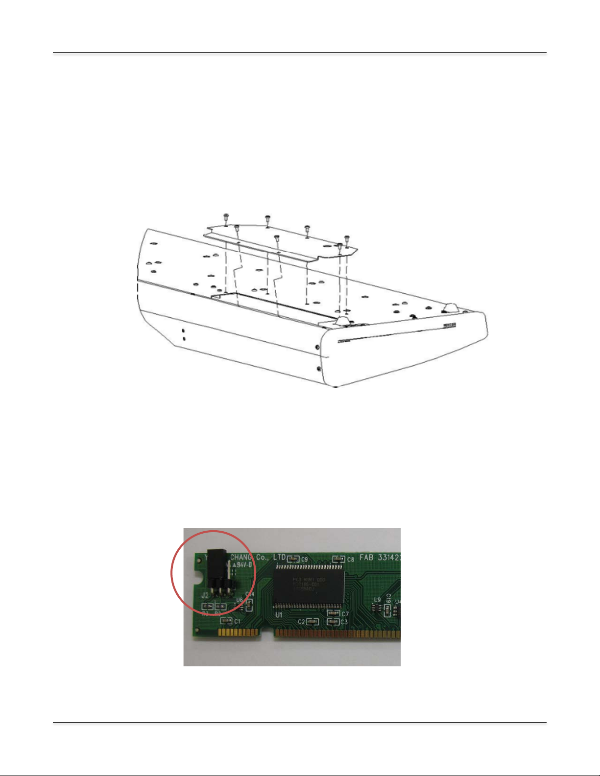
4. Using a #2 (small) Phillips screwdriver, remove the seven screws that secure the access panel,
as shown in Figure 1.
Figure 1: Removing the access panel
Configuring the Circuit Board
The circuit board for the Expansion Kit works for both the PC3 and the PC3K. A three-pin header
at the upper left corner of the board makes this possible. A jumper (a small plastic connector)
connects two of the three pins, and configures the board for either the PC3 or the PC3K. Figure 2
shows the jumper connecting pins 1 and 2 (the two left-hand pins). This is the correct
configuration for the PC3K.
Figure 2: Jumper position for PC3K
Page 6

Preparing For Hardware Ins t al lation
6
Figure 4: Deoxidizing the board
Figure 3: Jumper position for PC3
If you’re installing the Expansion Kit into a PC3K, you can proceed to the next section,
Deoxidizing the Contacts. If you’re installing into a PC3, you’ll need to move the jumper so that it
connects pins 2 and 3 (the two right-hand pins).
1. Grasp the jumper firmly, and slide it off the pins. Be careful not to bend the pins.
2. Slide the jumper onto the two right-hand pins, and push it firmly into place.
Deoxidizing the Contacts
During shipping and storage, the gold contacts on the
circuit board may have become oxidized, which can
prevent proper operation. To ensure the best
performance, your expansion kit includes a small
swab impregnated with deoxIT. Use the deoxIT to
clean the contacts, as shown in Figure 4.
Be careful not to touch the contacts with your bare
fingers; this will cause further oxidation.
You may want to use a plastic glove to make sure the
contacts stay clean, and to avoid getting deoxIT on
your hands.
Once you’ve deoxidized the contacts, you’re ready to
install the expansion board. We recommend saving
the deoxIT cloth in its plastic bag, in case you need
to clean the contacts again.
Please be sure to follow the hardware installation
instructions for the appropriate model.
Page 7

Hardware Installation: PC3
7
Figure 5: Identifying Bank 1
Hardware Installation: PC3
1. Identify Bank 1 on the main circuit board. There are two slots on the main board. Bank 1 is the
slot that is closer to you. If necessary, gently press the retaining clips at the edges of the slot into
the open position.
2. Grasp the expansion board at the top and center, with the chips facing away from you. The
contacts should be at the bottom. Note the notches at the bottom and center of the expansion
board. These notches help you align the board in the slot.
3. Holding the expansion board in a vertical position, insert it into the Bank 1, aligning the notches
with the partitions in the socket.
IMPORTANT NOTE: You may notice that Bank 0 is labeled EXPANSION SOUND
ROM. This is NOT the correct slot, despite the labeling. Be sure to install the expansion
board into Bank 1.
4. Press the board firmly into the slot, then squeeze the two hinged clips at the ends of the slot
until they snap into the closed position. This will require several pounds of pressure on the
expansion board; make sure to apply the pressure vertically, to avoid putting stress on the
expansion board or the slot. You may need to snap one clip first, then the other.
Page 8

8
5. Replace the access panel.
Figure 7: Identifying Bank 0
Figure 6: Expansion board installed in Bank 1
Hardware Ins t allation: PC3
6. Proceed to Verifying the Installation: PC3 on page 9.
Hardware Installation: PC3K
1. Identify Bank 0 on the main circuit board. There are two slots on the main board. Bank 1
already contains the 128 Mb PC3K flash memory board. Bank 0 is the empty slot.
Page 9

Hardware Ins t allation: PC3K
9
Figure 8: Expansion board installed in Bank 0
2. Grasp the expansion board at the top and center, with the chips facing away from you. The
contacts should be at the bottom. Note the notches at the bottom and center of the expansion
board. These notches help you align the expansion board in the slot on the main board.
3. Holding the expansion board in a vertical position, insert it into the Bank 0, aligning the notches
with the partitions in the socket.
4. Press the board firmly into the slot, then squeeze the two hinged clips at the ends of the slot
until they snap into the closed position. This will require several pounds of pressure on the
expansion board; make sure to apply the pressure vertically, to avoid putting stress on the
expansion board or the slot. You may need to snap one clip first, then the other.
5. Replace the access panel.
6. Proceed to Verifying the Installation: PC3K on page 13.
Verifying the Installation: PC3
You’ll need to run a few diagnostic tests to make sure that your expansion board is properly
installed and fully functional.
1. Reconnect the power supply and turn your instrument on.
2. Press the MASTER button to enter Master mode.
Page 10

Verifying The Install ation: PC3
10
3. Press SOFT Button 6 (more) three times; you’ll see the following page, which includes the
EXPAND option.
4. Use SOFT Button 3 to select the EXPAND option. You should see the following page. If so,
proceed to step 5. (Note: the diagnostic program refers to Slots, even though the main circuit
board uses the term Bank. These terms mean the same thing.)
You’ll see the following page if you’ve installed the expansion board in the wrong slot.
Page 11

Verifying The Installation: PC3
11
The following page appears if you’ve positioned the jumper on the expansion board incorrectly.
Turn off your instrument, disconnect the power supply, open the access panel, remove the
expansion board, and repeat the instructions in Preparing for Hardware Installation on page 4,
making sure to position the jumper correctly.
If you’ve configured the expansion board correctly, but the PC3’s display shows Empty DIMM
slot for Bank 1, you may not have installed the expansion board properly. Turn off your
instrument, disconnect the power supply, and repeat the instructions in Hardware Installation:
PC3 on page 7.
If you’ve configured the expansion board correctly, and have properly installed the board in
Bank 1, but you still see Empty DIMM slot for Bank 1, there may be a problem with the board
itself. The diagnostics in step 5 can help you determine if it’s a problem with the installation, or
with the board itself.
5. Use the UP/DOWN arrow keys to select Slot 1. Press SOFT button 1 (TEST) to run the
diagnostic on the selected slot. The test should run for about a minute. If the test succeeds,
you’ll see the following:
Congratulations! You’re ready to start using your ROM expansion. If the test fails, it may be for
any of the following reasons.
Page 12

Verifying The Install ation: PC3
12
If you’ve installed the expansion board in the wrong slot, you’ll see the following:
In this case, turn off your instrument, disconnect the power supply, and repeat the instructions in
Hardware Installation: PC3 on page 7.
You may see any of the following results if there’s an issue with the expansion board (either
poor contact due to improper positioning or oxidation on the contacts, or a malfunction of the
board itself).
An error in the address bus gives results like the following (it won’t look exactly like this):
A data bus error results in a page that looks something like this:
Page 13

Verifying The Installation: PC3
13
You’ll see the following if there’s a checksum error, which may indicate a malfunction of the
expansion board:
If you encounter any of these errors, you may be able to correct them by carefully reseating the
expansion board in Bank 1. Another application of deoxIT to the contacts may also correct the
problem. Both of these procedures may help if you encounter problems after using the ROM
expansion successfully.
If you’re unable to get a successful test after trying all of these procedures, please contact
Kurzweil Customer Support. See page ii for contact information.
Verifying the Installation: PC3K
You’ll need to run a few diagnostic tests to make sure that your expansion board is properly
installed and fully functional.
1. Reconnect the power supply and turn your instrument on.
2. Press the MASTER button to enter Master mode.
3. Press SOFT Button 6 (more) three times; you’ll see the following page, which includes the
EXPAND option.
Page 14

Verifying The Install ati on: PC3 K
14
4. Use SOFT Button 3 to select the EXPAND option. You should see the following page. If so,
proceed to step 5. (Note: the diagnostic program refers to Slots, even though the main circuit
board uses the term Bank. These terms mean the same thing.) If so, proceed to step 5.
The following page appears if you’ve positioned the jumper on the expansion board incorrectly.
Turn off your instrument, disconnect the power supply, open the access panel, remove the
expansion board, and repeat the instructions in Preparing for Hardware Installation on page 4,
making sure to position the jumper correctly.
If you’ve configured the expansion board correctly, but the PC3’s display shows Empty DIMM
slot for Bank 0, you may not have installed the expansion board properly. Turn off your
instrument, disconnect the power supply, and repeat the instructions in Hardware Installation:
PC3K on page 8.
If you’ve configured the expansion board correctly, and have properly installed the board in
Bank 0, but you still see Empty DIMM slot for Bank 0, there may be a problem with the board
itself. The diagnostics in step 5 can help you determine if it’s a problem with the installation, or
with the board itself.
Page 15

Verifying The Installation: PC3K
15
5. Use the UP/DOWN arrow keys to select Bank 0. Press SOFT button 1 (TEST) to run the
diagnostic. The test should run for about a minute. If the test succeeds, you’ll see the following:
Congratulations! You’re ready to start using your ROM expansion. If the test fails, it may be for
any of the following reasons.
You may see any of the following results if there’s an issue with the expansion board (either
poor contact due to improper positioning or oxidation on the contacts, or a malfunction of the
board itself).
An error in the address bus gives results like the following (it won’t look exactly like this):
A data bus error results in a page that looks something like this:
Page 16

Verifying The Install ati on: PC3 K
16
You’ll see the following if there’s a checksum error, which may indicate a malfunction of the
expansion board:
If you encounter any of these errors, you may be able to correct them by carefully reseating the
expansion board in Bank 0. Another application of deoxIT to the contacts may also correct the
problem. Both of these procedures may help if you encounter problems after using the ROM
expansion successfully.
If you’re unable to get a successful test after trying all of these procedures, please contact
Kurzweil Customer Support. See page ii for contact information.
 Loading...