

Page 1

K
DFX
V2
M usician’ s Reference
© Y oung Chang Co., Ltd. 2002. All rights reserved. Permission is granted to r eprint up to two copies of this manual for personal use.
Kurzweil ® is a product line of Young Chang Co., Ltd. Y oung Chang®, Kurzweil ® , V. A. S. T. ®, KDFX®, Pitcher®, and LaserV erb®, KSP8 ™,
K2600™, K2500™, and K2000™ are trademarks of Young Chang Co., Ltd. SmartMedia™ is a trademark of T oshiba Corporation. ADAT® is a
registered trademark of Alesis Corporation. All other products and brand names are trademarks or registered trademarks of their respective
companies. Product features and specifications are subject to change without notice.
Part Number: 910379, Re v. B
Page 2

Young Chang International Contacts
Contact the nearest Young Chang office listed below to locate your local Young Chang/ Kurzweil representative.
Young Chang America, Inc.
P.O. Box 99995
Lakewood, WA 98499-0995
Tel: 1-253-589-3200
Fax: 1-253-984-0245
Young Chang Co., Ltd.
178-55 Gajwa-Dong
Seo-Ku, Inchon, Korea 404-714
Tel: 011-82-32-570-1380
Fax: 011-82-32-570-1218
Young Chang America, Inc. (Canadian Division)
3650 Victoria Park Ave. Suite 105
Toronto, Ontario Canada M2H 3P7
Tel: 1-416-492-9899
Fax: 1-416-492-9299
W orld Wide Web Home Page
http://www.kurzweilmusicsystems.com
ii
Page 3

Table of Contents
Young Chang International Contacts . . . . . . . . . . . . . . . . . . . . . . . . . . . . . . ii
Introducing KDFX Version 2 . . . . . . . . . . . . . . . . . . . . . . . . . . . . . . . . . . . 1-1
Overview . . . . . . . . . . . . . . . . . . . . . . . . . . . . . . . . . . . . . . . . . . . . . . . . . . . 1-1
Additions and Changes to Effects Mode Pages . . . . . . . . . . . . . . . . . . . . . . 1-2
New Button Presses for Bypassing/Enabling Effects . . . . . . . . . . . . . . . . . 1-2
MAIN Page . . . . . . . . . . . . . . . . . . . . . . . . . . . . . . . . . . . . . . . . . . . . . . . . . 1-3
Soft Buttons in Effects Mode . . . . . . . . . . . . . . . . . . . . . . . . . . . . . . . . . . . . 1-4
Soft Buttons: Configuring Bypasses . . . . . . . . . . . . . . . . . . . . . . . . . . . . . . 1-4
Effects Bus Editor . . . . . . . . . . . . . . . . . . . . . . . . . . . . . . . . . . . . . . . . . . . . 1-5
Effects Send Page . . . . . . . . . . . . . . . . . . . . . . . . . . . . . . . . . . . . . . . . . . . . 1-6
The CTRL Page . . . . . . . . . . . . . . . . . . . . . . . . . . . . . . . . . . . . . . . . . . . . . . 1-7
Effects Control Mode (FXCtrl) . . . . . . . . . . . . . . . . . . . . . . . . . . . . . . . . . . 1-7
Effects Control in Embedded Editors . . . . . . . . . . . . . . . . . . . . . . . . . . . . . 1-7
Bypass and Mute pages . . . . . . . . . . . . . . . . . . . . . . . . . . . . . . . . . . . . . . . . 1-8
Creating a Custom Bypass Scene . . . . . . . . . . . . . . . . . . . . . . . . . . . . . . . . 1-8
The EQBYP Page . . . . . . . . . . . . . . . . . . . . . . . . . . . . . . . . . . . . . . . . . . . . 1-9
The FX Bypass Page . . . . . . . . . . . . . . . . . . . . . . . . . . . . . . . . . . . . . . . . . . 1-9
The Bus Mute Page . . . . . . . . . . . . . . . . . . . . . . . . . . . . . . . . . . . . . . . . . . . 1-10
Chaining Effects . . . . . . . . . . . . . . . . . . . . . . . . . . . . . . . . . . . . . . . . . . . . . . 1-11
Gain Staging in Effects Chains . . . . . . . . . . . . . . . . . . . . . . . . . . . . . . . . . . 1-12
Checking Out Some Chains . . . . . . . . . . . . . . . . . . . . . . . . . . . . . . . . . . . . . 1-12
KDFX V2 Objects . . . . . . . . . . . . . . . . . . . . . . . . . . . . . . . . . . . . . . . . . . . . 1-13
New FX Algorithms . . . . . . . . . . . . . . . . . . . . . . . . . . . . . . . . . . . . . . . . . . . 1-13
Additional FX Algorithms new to K2500 . . . . . . . . . . . . . . . . . . . . . . . . . . 1-13
New FX Studios . . . . . . . . . . . . . . . . . . . . . . . . . . . . . . . . . . . . . . . . . . . . . . 1-13
Additional FX Studios new to K2500 . . . . . . . . . . . . . . . . . . . . . . . . . . . . . 1-14
New FX Presets . . . . . . . . . . . . . . . . . . . . . . . . . . . . . . . . . . . . . . . . . . . . . . 1-15
Additional FX Presets new to K2500 . . . . . . . . . . . . . . . . . . . . . . . . . . . . . 1-16
A Tour of KDFX V2 . . . . . . . . . . . . . . . . . . . . . . . . . . . . . . . . . . . . . . . . . . . 2-1
Load the Tutorial files . . . . . . . . . . . . . . . . . . . . . . . . . . . . . . . . . . . . . . . . . 2-1
A Simple Studio . . . . . . . . . . . . . . . . . . . . . . . . . . . . . . . . . . . . . . . . . . . . . . 2-2
The FXBus Page . . . . . . . . . . . . . . . . . . . . . . . . . . . . . . . . . . . . . . . . . . . . . 2-2
The INPUT Page . . . . . . . . . . . . . . . . . . . . . . . . . . . . . . . . . . . . . . . . . . . . . 2-3
The FXSEND Page . . . . . . . . . . . . . . . . . . . . . . . . . . . . . . . . . . . . . . . . . . . 2-4
The AUXFX Page . . . . . . . . . . . . . . . . . . . . . . . . . . . . . . . . . . . . . . . . . . . . 2-5
The OUTPUT Page . . . . . . . . . . . . . . . . . . . . . . . . . . . . . . . . . . . . . . . . . . . 2-5
A More Complex Studio . . . . . . . . . . . . . . . . . . . . . . . . . . . . . . . . . . . . . . . 2-6
FXBus1 . . . . . . . . . . . . . . . . . . . . . . . . . . . . . . . . . . . . . . . . . . . . . . . . . . . . 2-6
FXBus2 . . . . . . . . . . . . . . . . . . . . . . . . . . . . . . . . . . . . . . . . . . . . . . . . . . . . 2-7
Inputs . . . . . . . . . . . . . . . . . . . . . . . . . . . . . . . . . . . . . . . . . . . . . . . . . . . . . . 2-7
Table of Contents-1
Page 4

AuxFX Bus . . . . . . . . . . . . . . . . . . . . . . . . . . . . . . . . . . . . . . . . . . . . . . . . . 2-8
Outputs . . . . . . . . . . . . . . . . . . . . . . . . . . . . . . . . . . . . . . . . . . . . . . . . . . . . . 2-9
Chaining Effects . . . . . . . . . . . . . . . . . . . . . . . . . . . . . . . . . . . . . . . . . . . . . . 2-10
A Complex Studio with Real-Time Control . . . . . . . . . . . . . . . . . . . . . . . . 2-13
Setting the FXCTRL . . . . . . . . . . . . . . . . . . . . . . . . . . . . . . . . . . . . . . . . . . 2-13
The Setup . . . . . . . . . . . . . . . . . . . . . . . . . . . . . . . . . . . . . . . . . . . . . . . . . . . 2-13
Looking at the Studio . . . . . . . . . . . . . . . . . . . . . . . . . . . . . . . . . . . . . . . . . . 2-14
Setting Up FXMods . . . . . . . . . . . . . . . . . . . . . . . . . . . . . . . . . . . . . . . . . . . 2-15
A Note About Effects in Setups . . . . . . . . . . . . . . . . . . . . . . . . . . . . . . . . . . 2-19
Building Your Own . . . . . . . . . . . . . . . . . . . . . . . . . . . . . . . . . . . . . . . . . . . 2-20
Algorithm Reference . . . . . . . . . . . . . . . . . . . . . . . . . . . . . . . . . . . . . . . . . . 3-1
Degen Regen BPM . . . . . . . . . . . . . . . . . . . . . . . . . . . . . . . . . . . . . . . . . . . . 3-2
Switch Loops. . . . . . . . . . . . . . . . . . . . . . . . . . . . . . . . . . . . . . . . . . . . . . . . . 3-7
Moving Delay . . . . . . . . . . . . . . . . . . . . . . . . . . . . . . . . . . . . . . . . . . . . . . . . 3-10
Allpass Phaser 3 . . . . . . . . . . . . . . . . . . . . . . . . . . . . . . . . . . . . . . . . . . . . . . 3-11
VC+Dist+1Rotor 2 . . . . . . . . . . . . . . . . . . . . . . . . . . . . . . . . . . . . . . . . . . . . 3-13
VC+Dist+HiLoRotr . . . . . . . . . . . . . . . . . . . . . . . . . . . . . . . . . . . . . . . . . . . 3-13
VC+Tube+Rotor 4 . . . . . . . . . . . . . . . . . . . . . . . . . . . . . . . . . . . . . . . . . . . . 3-13
Rotor 1. . . . . . . . . . . . . . . . . . . . . . . . . . . . . . . . . . . . . . . . . . . . . . . . . . . . . . 3-13
VC+Dist+HiLoRot2 . . . . . . . . . . . . . . . . . . . . . . . . . . . . . . . . . . . . . . . . . . . 3-13
Subtle Distort . . . . . . . . . . . . . . . . . . . . . . . . . . . . . . . . . . . . . . . . . . . . . . . . 3-22
Quantize+Alias . . . . . . . . . . . . . . . . . . . . . . . . . . . . . . . . . . . . . . . . . . . . . . . 3-23
Pitcher+MiniVerb . . . . . . . . . . . . . . . . . . . . . . . . . . . . . . . . . . . . . . . . . . . . . 3-26
Reverb+Compress. . . . . . . . . . . . . . . . . . . . . . . . . . . . . . . . . . . . . . . . . . . . . 3-29
St Chorus+Delay. . . . . . . . . . . . . . . . . . . . . . . . . . . . . . . . . . . . . . . . . . . . . . 3-32
St Flange+Delay . . . . . . . . . . . . . . . . . . . . . . . . . . . . . . . . . . . . . . . . . . . . . . 3-32
Gate+Cmp[EQ]+Vrb. . . . . . . . . . . . . . . . . . . . . . . . . . . . . . . . . . . . . . . . . . . 3-33
Gate+TubeAmp. . . . . . . . . . . . . . . . . . . . . . . . . . . . . . . . . . . . . . . . . . . . . . . 3-37
Revrse LaserVerb . . . . . . . . . . . . . . . . . . . . . . . . . . . . . . . . . . . . . . . . . . . . . 3-40
Gated LaserVerb. . . . . . . . . . . . . . . . . . . . . . . . . . . . . . . . . . . . . . . . . . . . . . 3-43
Poly Pitcher. . . . . . . . . . . . . . . . . . . . . . . . . . . . . . . . . . . . . . . . . . . . . . . . . . 3-46
Frequency Offset. . . . . . . . . . . . . . . . . . . . . . . . . . . . . . . . . . . . . . . . . . . . . . 3-48
MutualFreqOffset . . . . . . . . . . . . . . . . . . . . . . . . . . . . . . . . . . . . . . . . . . . . . 3-48
WackedPitchLFO . . . . . . . . . . . . . . . . . . . . . . . . . . . . . . . . . . . . . . . . . . . . . 3-52
Chaos! . . . . . . . . . . . . . . . . . . . . . . . . . . . . . . . . . . . . . . . . . . . . . . . . . . . . . . 3-54
Band Compress. . . . . . . . . . . . . . . . . . . . . . . . . . . . . . . . . . . . . . . . . . . . . . . 3-57
CompressDualTime . . . . . . . . . . . . . . . . . . . . . . . . . . . . . . . . . . . . . . . . . . . 3-61
3 Band EQ. . . . . . . . . . . . . . . . . . . . . . . . . . . . . . . . . . . . . . . . . . . . . . . . . . . 3-65
HF Stimulate 1 . . . . . . . . . . . . . . . . . . . . . . . . . . . . . . . . . . . . . . . . . . . . . . . 3-66
HarmonicSuppress . . . . . . . . . . . . . . . . . . . . . . . . . . . . . . . . . . . . . . . . . . . . 3-67
Table of Contents-2
Page 5
Chapter 1
Introducing KDFX Version 2
Overview
KDFX V2 gives you more control than ever over the effects in each studio, through several
enhancements:
• You can assemble chains of up to four FX Presets on an FXBus.
• You have access to 26 new KDFX algorithms (29 for K2500).
• You can mute or bypass effects and EQ for individual FXBuses. You can now keep effects
bypassed outside the program editor, as well.
• You can get to Effects Mode directly from Program, Setup, and Song modes—you don’t
have to go through another editor first.
If you are familiar with Version 1 of KDFX, you will notice that there are several new pages and
parameters giving you access to the new features. You’ll also notice some changes to existing
pages. The INPUT, AUXFX, and OUTPUT pages have not changed at all with KDFX V2,
however.
The following tables give a brief explanation of the major additions and changes in KDFX V2.
Page Description What’s Different
KDFXMode:MAIN
EditStudio:FXBUS
EditStudio:FXSEND
KDFXMode:CTRL
KDFXMode:EQBYP
KDFXMode:FXBYP
KDFXMode:BUSMUT
Displays studio assignment. Also, for each
insert FXBus, displays FX Preset assignment,
bypass/mute, and PAU assignment.
New soft buttons for adding/deleting
FX Presets on current FXBus; new soft button
for bringing up the new FXSEND page.
Directs the send of each Insert FXBus to either
the default stereo Mix bus or the AuxFX bus,
with balance control for each.
Controls FXCtrl (formerly FX Mode) and
FX Chan, as well as dither.
Controls EQ mute/bypass for each Insert
FXBus.
Controls independent active/bypassed status
for each Insert FXBus and the AuxFX bus.
Controls independent active/muted status for
each Insert FXBus and the AuxFX bus.
Was EffectsMode page; controlled studio
assignment, FX Mode and FX Chan, and
dither (noise-floor adjustment).
P AU assignment is handled for each FXBus
individually; Level and Balance for each
FXBus are part of new FXSend page; New
feature: you can chain multiple Presets
together on an insert bus using the Add and
Remove buttons.
Relocates Lvl and Bal parameters from the
FXBus page.
Replaces functionality of EffectsMode
page, which no longer exists.
New feature.
New feature.
New feature.
Page 6

Introducing KDFX Version 2
Additions and Changes to Effects Mode Pages
Additions and Changes to Effects Mode Pages
Prior to V2, there was a single Effects Mode page, which was responsible primarily for setting
the FX Mode and FX Chan parameters. This pair of parameters affected how the K2600/K2500
selected studios when you changed programs, setups, or songs. You would get to the
EffectsMode page by pressing the Effects button while in a performance mode (not while in an
editor). While inside an editor, the Effects button was used to globally bypass or enable the
effects.
There’s much more going on with V2, so we’ve added several pages, and moved a number of
parameters into more logical groupings. Pressing the Effects button now takes you to the
KDFXMode:MAIN page, which gives you easy access to the Effects Mode pages.
The Studio Editor has some new soft buttons and pages to accommodate effect chaining in
KDFX V2. The Add and Remove buttons on the FXBUS page let you create and modify chains
on the buses. The FX Send and Aux Send fields and graphics that were pr eviously shown on the
FXBUS page are now found on their own new page, FXSEND. Pressing the right more > button
on the FXBUS page reveals the FXSEND soft button, as well as the familiar AUXFX and
OUTPUT buttons.
New Button Presses for Bypassing/Enabling Effects
As a result of the new flexibility we’ve added, bypassing or enabling effects now takes an extra
button press or two, because you have to press Effects , then BypAll or Enable . Also, you may
need to press Exit or Effects again, depending on whether you're just toggling the effects on and
off, or whether you are leaving the effects bypassed and returning to an editor. See page 1-4 for
information on the new bypass features.
1-2
Page 7

MAIN Page
The KDFXMode:MAIN page gives you a summary view of the current effects configuration,
including the current studio, the FX Presets assigned to each of the five effects buses, and the
bypass status of each bus.
KDFXMode:MAIN||||FXCtrl:Auto||||<>Enable
Studio: 113|PltEnvFI4T|Plate| ||||||Free:0
FX1|||43|Plebe|Chamber||||||||-|||Size:1
FX2|||902|Synth|Env|Filter||||B|||Size:2
FX3|||735|Bap|ba_da_dap|||||||-|||Size:1
FX4|||0|None||||||||||||||||||B|||Size:0
Aux|| | 103|Bi g Predel a yPlate | |||B|| | Size:3
MAIN| | CTRL|| | EQBYP| | FXBYP| | BUSMUT | Enable |
Figure 1-1 Effects mode: the KDFXMode:MAIN page
As with every other page, the top line of the KDFXMode:MAIN page identifies the page you’re
on. It also shows you two other important features of Effects mode:
FXCtrl: Effects-control status. Prior to V2, this was called FX Mode. The functionality
Enable state: Shows whether KDFX is currently enabled or if any part of KDFX is bypassed or
hasn’t changed, but we renamed it because it’s now a parameter on the Ctrl page,
which is accessible with the CTRL soft button.
muted.
Introducing KDFX Version 2
MAIN Page
The second line of the display shows the ID and name of the current studio. When you enter
KDFX Mode directly (i.e., not through another one of the K2500/K2600’s editors) you can scroll
through the displayed list of studios. This allows you to choose a different studio on the
KDFXMode:MAIN page. When FXCTRL is set to Master (see page 1-7), you can also do this,
even when you have entered KDFX Mode from within another editor.
If you select the studio then press the Edit button, you’ll go to EditStudio:FXBUS page, where
you can make changes to each bus within the studio.
The second line also shows the number of PAUs available for the current studio (“Free:” on the
right-hand side). This number will be 0–4, since in each studio four PAUs are available for the
four insert FXBuses (the AuxFX bus has its own fixed set of three PAUs).
The next five lines show the IDs and names of the FX Presets assigned to the five effects buses
(insert FXBuses 1–4 and the AuxFX bus). You can’t change these assignments on the
KDFXMode:MAIN page; to do that you would highlight the Studio name (line two of this page)
then press Edit . This takes you to the Studio Editor, on the appropriate FXBUS page for the first
bus. As in KDFX V1, use the Chan/Bank buttons to move between buses.
Each of these five lines also indicates the bypass status for the five buses, as well as the number
of PAUs used by each FXBus. A dash (
bypassed/disabled. You can change the bypass status for a bus by moving the cursor to this
field and changing it with either the alpha wheel or pressing one of the increment/decrement
buttons.
The size of each FX Preset is measured in PAUs (processor allocation units). FXBuses 1–4 can all
use up to four PAUs, but the studio can use a maximum of four total PAUs. The AuxFX bus can
use up to three PAUs independent of the insert FXBuses.
) indicates active/enabled, and
-
indicates
B
1-3
Page 8

Introducing KDFX Version 2
MAIN Page
Soft Buttons in Effects Mode
The MAIN button takes you to the KDFXMode:MAIN page, where you can view the current
studio and the FX Presets assigned to the five KDFX buses.
The CTRL button takes you to the KDFXMode:CTRL page, which contains parameters that
determine which studio gets selected when you select a program, setup, or song. You also use
the KDFXMode:CTRL page to change dither and digital word size settings.
Soft Buttons: Configuring Bypasses
You can individually bypass any of the EQ and effects inputs, and also mute any of the FXBuses
(the four insert FXBuses and the AuxFX bus). In the enabled state, nothing is muted or bypassed.
The K2600/K2500 always starts up in the enabled state.
Use these soft buttons to perform bypasses and muting:
EQBYP Displays EQ Bypass page, where you can bypass the EQ on each individual
input bus.
FXBYP Displays FX Bypass page, where you can bypass the effects on individual
FXBuses.
BUSMUT Displays the BusMute page, where you can mute the output of individual
FXBuses.
BypAll/Enable Toggles between enabled state and default bypass state (all buses bypassed,
none muted). If you have created a custom bypass scene, BypAll resets it to
the default bypass state. See page 1-8 for information on creating a custom
bypass scene.
You may also use either of the Chan/Bank buttons to toggle between enabled
and bypassed states. This will often be preferable, since Chan/Bank, unlike
BypAll, does not reset the bypass state to the default (all buses bypassed,
none muted). Instead, Chan/Bank toggles between the enabled state and any
custom bypass scene you may have created, allowing you to audition a studio
with and without bypasses.
1-4
Page 9

Effects Bus Editor
The revised FXBus Editor lets you create effects Preset chains on any of the four stereo effects
buses. See page 1-11 for more information about chaining effects.
EditStudio:FXBUS|Size:3|Free:0|<>FXBus:1
|||||qWWWWT|||||||||||||||||||||||||||||
FX1|!kRvrb©!!!!!!!!!!!!!!!!!!!!!!!!!!!h|
|||||CVVVVB|||||||||||||||||||||||||||||
FX:|1|NiceLittleBooth|||||||||||||||||||
Wet/Dry|||:42%wet|||||||||||||||||||||||
Out|Gain||:0.0dB|||||||||||Alloc:Auto|||
<more||INPUT||FXBUS|||Add||Remove||more>
Figure 1-2 Effects Bus Editor display -- single effect
EditStudio:FXBUS|Size:1|Free:0|<>FXBus:1
|||||qWWWWT|||qwwwwt|||qwwwwt|||qwwwwt||
FX1|!kRvrb©!!!kChorg!!!kDly|g!!!kFlngg!h
|||||CVVVVB|||CVVVVB|||CVVVVB|||CVVVVB||
FX:|1|NiceLittleBooth|||||||||||||||||||
Wet/Dry|||:42%wet|||||||||||||||||||||||
Out|Gain||:0.0dB|||||||||||Alloc:Auto|||
<more||INPUT||FXBUS|||Add||Remove||more>
Introducing KDFX Version 2
Effects Bus Editor
Figure 1-3 Effects Bus Editor display -- four chained effects
The Add and Remove buttons allow you to define your own chains of effects using up to four
FX Presets. The Add button creates an effects block (shown as a box) to the right of the current
cursor position in the effects chain. You can use a total of four effects in any studio, so if you
create a four-block effects chain on a bus then you won’t be able to use any effects on the other
buses in that studio. Your K2500/K2600 keeps track of effects usage for you, and won’t let you
add an effects block to a bus if you’re already max’ed out.
The Remove button deletes the effects block that the FXBUS editor cursor is on. Adding and
deleting effects blocks may cause audio glitches in any signal path and should not be done
during critical listening.
Each FX Preset in an effect chain has two “override” parameters (BusMods) that are displayed
when that FX block is selected. By selecting the name of an override parameter (e.g., Wet/Dry),
you can scroll to choose from any other available parameter.
Each effect also has its full complement of real time modulators as defined and displayed in the
Program and Setup editors.
1-5
Page 10

Introducing KDFX Version 2
Effects Send Page
Effects Send Page
The FXSEND page lets you send the output of each stereo effects bus to the stereo mixdown and
auxiliary buses.
In KDFX V1, these sends were on the EditStudio:FXBUS page.
EditStudio:FXSEND|||||||||||||<>FXBus:1|
|||||!!!!!!!!!!!!!!!!!!!!!!!!!!!!!!!!!!h
||||||0wwwwt||||||||||0wwwwt|||||||||
||||||KAux|1||||||||||KMix|1|||||||||
||||||CVVVVB||||||||||CVVVVB|||||||||
|||||||Aux|Lvl:0.0dB|||Mix|Lvl:0.0dB||||
|||||||Aux|Pan:0%||||||Mix|Pan:0%|||||||
||||||||||||||||||||||||||||||||||||||||
<more||FXSEND|AUXFX|OUTPUT|||||||||more>
Figure 1-4 Effects Bus Send display
1-6
Page 11

The CTRL Page
The CTRL page is where you set a variety of important parameters for KDFX, including the
Effects Control Mode (FXCtrl) for the current studio; this parameter was known as FX Mode in
KDFX V1, and its function is the same in KDFX V2.
As in KDFX V1, the CTRL page is also where you set the FX Channel and set the Dither level for
the current studio. Depending on the options you have installed, this is also where you’ll be able
to change word length for digital output.
KDFXMode:CTRL||||FXCtrl:Auto||||<>Enable
Studio:49|Sndboard|Room|Hall||||||||||||
FXCtrl:Auto|||||||||||||||||||||||||||||
FXChan:Current||||||||||||||||||||||||||
||||||||||||||||||||||||||||||||||||||||
||||||||||||||||||||||||||||||||||||||||
Dither:Medium|||||||||||||||||||||||||||
MAIN||CTRL|||EQBYP||FXBYP||BUSMUT|Enable
Figure 1-5 Effects Control page
Effects Control Mode (FXCtrl)
FXCtrl determines how the K2500/K2600 selects studios as you change programs or setups, and
determines whether you have real-time control over studio parameters—in other words,
whether FXMods are active.
Introducing KDFX Version 2
The CTRL Page
If the value of FXCtrl is Program or Auto, then as you change programs in Program mode, the
K2500/K2600 also loads the studio linked with that program. This activates all the FXMods
defined within the program. If the value of FXCtrl is Setup or Auto, then as you change setups
in Setup mode, the K2500/K2600 also loads the studio linked with that setup. This activates all
the FXMods defined within the setup. If the value of FXCtrl is Auto, and the value of FX Chan is
Current, then when you’re in Program, Setup, Quick Access, or Song mode, programs, setups
and songs automatically use their corresponding studios. In Program, Setup, and Quick Access
modes, the studio corresponds to the current program or setup. In Song mode, the studio
corresponds to the program on the song’s assigned effects channel (which is determined by the
value of the EffectChan parameter on the COMMON page in the Song Editor).
If the value of FXCtrl is Master, changing programs or setups does not load an associated studio;
the current studio is defined by the Studio parameter on the Effects Mode page. Any FXMods
defined in the current program or setup are inactive.
Effects Control in Embedded Editors
In the parlance of V.A.S.T., an embedded editor is an editor that you enter while you are already
in another editor. An example of this would be entering the KDFX Studio Editor while you are
already in the Program Editor. In this sort of situation, an editor may function differently than if
you had entered it directly from a performance mode.
When you enter the KDFX Studio Editor from within another editor (for example, you are
already in the Program Editor when you press the Effects button), KDFX will revert FXCtrl to
Auto and FXChan to Current if you attempt to perform an operation that the software doesn’t
support. For example, you cannot change a program’s assigned studio by pressing the Effects
button to enter the KDFX Editor while you are already within the Program Editor. If you set
FXCtrl to Master you will be able to audition different studios, but the software will not let you
change a studio. The correct way to change the studio used by a program is to press the KDFX
soft button from within the Program Editor.
1-7
Page 12

Introducing KDFX Version 2
Bypass and Mute pages
Bypass and Mute pages
In KDFX V1, you could perform a global bypass by pressing the Effects button while inside an
editor. You could not bypass effects outside of an editor.
With KDFX V2, you can bypass effects buses, inside or outside of an editor, by pressing the
Effects button followed by either the BypAll soft button or one of the Chan/Bank buttons.
Although similar, the two methods are slightly different:
• The BypAll soft button globally bypasses all effects buses, and also r esets the default bypass
state to bypass all buses. When you press this soft button it changes into the Enable soft
button, allowing you to toggle between the state where all buses are bypassed and the state
where all are enabled.
• Either Chan/Bank button toggles between the enabled state and the current bypass state.
The current bypass state is either the default (all buses bypassed) or the custom bypass
scene you have created. See the section that follows for information about creating a bypass
scene.
Pressing the Effects button again, or pressing Exit, puts you back where you were.
Creating a Custom Bypass Scene
You create a custom bypass “scene” (e.g., effects bypassed on one bus, but not on the other
three) by using the soft buttons on the EQBYP, FXBYP, and BUSMUT pages to isolate sounds or
effects. You can then toggle between an all-enabled state and your custom scene by pressing
either of the Chan/Bank buttons (to the left of the display) while in KDFX Mode.
The system indicates whether anything at all is bypassed or muted by showing “Bypass” at the
far right of the top line on the display; if nothing is bypassed, this field shows “Enable.” Any
settings from the FXBYP page are also indicated on the KDFXMode:MAIN page as either a “B”
(bypassed) or a “-” (enabled). EQ Bypass and Bus Mute settings, however, are not indicated on
the KDFXMode:MAIN page. If you exit this mode with anything bypassed, the Effects button's
red LED stays lit to remind you that something is not active.
1-8
Page 13

Introducing KDFX Version 2
Bypass and Mute pages
The EQBYP Page
KDFXMode:EQBYP|||FXCtrl:Auto||||<>Enable
Studio:113|PltEnvFI4T|Plate|||||||||||||
||||||||||||||||||||||||||||||||||||||||
EQ|A|||LoShelf-HiShelf||||||||||||||:In|
EQ|B|||LoShelf-HiShelf||||||||||||||:Out
EQ|C|||Lopass1-HiShelf||||||||||||||:In|
EQ|D|||Hipass1-Lopass1||||||||||||||:In|
MAIN||EQ|A|||EQ|B|||EQ|C|||EQ|D|||||||||
Figure 1-6 EQ Bypass Page
The MAIN soft button takes you to the KDFXMode:MAIN page. The soft buttons EQ A, EQ B,
EQ C, and EQ D toggle the bypass/active status for the EQ on the corresponding input buses.
The EQBYP page looks a little different when there are mono inputs to the studio. In this case,
press the L/R soft button to toggle between left and right mono inputs for a bus.
KDFXMode:EQBYP|||FXCtrl:Auto||||<>Enable
Studio:113*PltEnvFI4T|Plate|||||||||||||
||||||||||||||||||||||||||||||||||||||||
EQ|A/L|LoShelf-HiShelf||||||||||||||:In|
EQ|B|||LoShelf-HiShelf||||||||||||||:Out
EQ|C|||Lopass1-HiShelf||||||||||||||:In|
EQ|D|||Hipass1-Lopass1||||||||||||||:In|
MAIN||EQ|A/L|EQ|B|||EQ|C|||EQ|D|||L/R||||
Figure 1-7 EQ Bypass Page with Mono Inputs
The FX Bypass Page
KDFXMode:FXBYP|||FXCtrl:Auto||||<>Enable
Studio:113|PltEnvFI4T|Plate|||||||||||||
FX1|||43|Plebe|Chamber||||||||||:Active
FX2|||158|Soft|Chorus|||||||||||:ByPass
FX3|||2|Stereo|Echoes|||||||||||:Active
||||||||||||||||||||||||||||||||||||||||
Aux|||31|Platey|Room||||||||||||:Active|
MAIN||FXBus1|FXBus2|FXBus3||||||||AuxFX|
Figure 1-8 FX Bypass Page
The MAIN soft button takes you to the MAIN page. The FX1–FX4 and AuxFX soft buttons
toggle Bypass/Active status for the effect on the corresponding bus.
1-9
Page 14

Introducing KDFX Version 2
Bypass and Mute pages
The Bus Mute Page
KDFXMode:BUSMUT||FXCtrl:Auto||||<>Enable
Studio:113|PltEnvFI4T|Plate|||||||||||||
FXBus1||43|Plebe|Chamber|||||||||:Active
FXBus2|158|Soft|Chorus|||||||||||:Muted|
FXBus3|||2|Stereo|Echoes|||||||||:Muted|
FXBus4|||---|||||||||||||||||||||:Active
AuxFX|||31|Platey|Room|||||||||||:Active
MAIN||FXBus1|FXBus2|FXBus3|FXBus4|AuxFX|
Figure 1-9 Bus Mute Page
The MAIN soft button takes you to the KDFXMode:MAIN page. The soft buttons
FXBus1–FXBus4 and AuxFX toggle the mute/active status for the corresponding input buses.
1-10
Page 15

Chaining Effects
One of the most powerful new features in KDFX V2 is effects chaining, which allows you to
send a signal through four consecutive KDFX effects. The screen below shows an example of
this:
EditStudio:FXBUS|Size:1|Free:0|<>FXBus:1
|||||qWWWWT|||qwwwwt|||qwwwwt|||qwwwwt||
FX1|!kRvrb©!!!kChorg!!!kDly|g!!!kFlngg!h
|||||CVVVVB|||CVVVVB|||CVVVVB|||CVVVVB||
FX:|1|NiceLittleBooth|||||||||||||||||||
Wet/Dry|||:42%wet|||||||||||||||||||||||
Out|Gain||:0.0dB|||||||||||Alloc:Auto|||
<more||INPUT||FXBUS|||Add||Remove||more>
Figure 1-10 Effects Bus Editor display -- four chained effects
Effects chaining allows the 4 PAUs of processing shared among Buses 1-4 of a Studio to be used
in series. You can chain one FX Preset into another, into another, up to four in a row, until you
run out of PAUs. This is done by removing processing “blocks” from one bus, and adding them
to another. As no effect is less than 1 PAU, and only 4 PAUs are available across Buses 1-4, any
Studio may have a maximum of 4 blocks, arranged however you please, in which to select
Presets (not counting the Aux bus which is unaffected by chaining).
Introducing KDFX Version 2
Chaining Effects
The FXBUS page has changed in KDFX V2 to allow for effect chaining. The chained effects are
shown at the top of the display (underneath the top menu line). As an example, start from
Program Mode, press the Effects button, then select Studio 700 Flanger Trio:
KDFXMode:MAIN||||FXCtrl:Auto||||<>Enable
Studio:700|Flanger|Trio|||||||||||Free:0
FX1a||180|Ned|Flangers||||||||-|||Size:1
||1b||172|Sweet|Flange||||||||-|||Size:1
||1c||181|Wispy|Flange||||||||-|||Size:1
||1d||40|SmallDrumChamber|||||-|||Size:1
Aux|||108|Roomitizer||||||||||-|||Size:2
MAIN||CTRL|||EQBYP||FXBYP||BUSMUT|Enable|
You can see that this studio has three flange effects, followed by a reverb. The effects are
numbered 1a through 1d to indicate that they are all part of FXBUS 1, instead of four separate
effects buses. Now press Edit to go into the Studio Editor. The top of the display shows the four
effects chained together . Each block contains an abbr eviation based on the algorithm used by the
Preset:
EditStudio:FXBUS|Size:1|Free:0|<>FXBus:1
|||||qWWWWT|||qwwwwt|||qwwwwt|||qwwwwt||
FX1|!kFlng©!!!kFlngg!!!kFlngg!!!kRvrbg!h
|||||CVVVVB|||CVVVVB|||CVVVVB|||CVVVVB||
FX:|180|Ned|Flangers||||||||||||||||||||
Wet/Dry|||:42%wet|||||||||||||||||||||||
Out|Gain||:0.0dB|||||||||||Alloc:Auto|||
<more||INPUT||FXBUS|||Add||Remove||more>
The name of the FX Preset for the currently highlighted block is now shown underneath the
signal path graphics. In this example, you will see the FX Preset Ned Flangers if the first block is
highlighted. You still have 2 Bus Overrides (or Bus Mods) per block, which appear just below
the name of the Preset.
1-11
Page 16

Introducing KDFX Version 2
Chaining Effects
Use the left and right cursor buttons to select each block. When a block is selected, move the
alpha wheel or press the + or - buttons to select a different FX Preset (you can also change the
Preset by cursoring to the full name of the Preset after the FX: label).
Notice that the unhighlighted blocks have a box around them. This shows they are active. Since
this studio has 4 blocks, each block can use only 1 PAU. If you select an effect that uses more
than one PAU, one of the blocks will become inactive and the box surrounding that block will
disappear . For example, if you change the first block to FX Preset 183 Narr owResFlange, the box
around block 4 disappears. The top line of the display shows you this FX Preset uses 2 PAUs. As
in the past, if the Allocation parameter is set to Auto, the lower number blocks have pr ecedence,
so block 4 is the one that becomes inactive. If you highlight block 4 at this point, you will see the
FX Preset shown in parenthesis, again showing it is not active.
The Chan/Bank buttons still move you through the four FXBUSes as in KDFX V1. Since no
effects are available in this case, you will see a line with no blocks on them if you look at any bus
except FXBUS 1. You can still use a bus to send another signal to the AUX without the chain, by
the way, since KDFX has been designed to offer you maximum flexibility.
Gain Staging in Effects Chains
When chaining Presets together, it is sometimes necessary to adjust the levels between blocks,
most often to pad the level going into the next block to prevent unwanted clipping. While most
algorithms have both an In Gain and an Out Gain parameter, In Gain is not selectable as a Bus
Mod. In fact, any Preset beyond the first in a chain cannot use In Gain, and will display the value
inside the Preset in parentheses. We suggest, when necessary, choosing Out Gain as a Bus Mod
to adjust the output level of an effect, instead of trying to pad the input of the following effect.
Of course, you can always edit FX Presets directly and customize them for your chain.
Checking Out Some Chains
For examples of studios with chains, check out studios 700-719. By setting the FX Ctrl parameter
(KDFXMode:CTRL page) to Master, and the OutPair parameter (MIDIMode:Channels page) to
KDFX-A, you can scroll through Programs on a given MIDI channel and audition these studios
as they were intended to be heard, with a variety of input source material.
1-12
Page 17

KDFX V2 Objects
Listed below are the new KDFX Objects added with version 5.xx (K2500) or 3.xx (K2600) of the
Base Objects file. These include new FX Algorithms, Presets, and Studios added to the
K2500/K2600 with the new object files. Objects marked “Additional XX new to K2500” were
previously available in the K2600 but not in the K2500.
New FX Algorithms
138 Degen Regen BPM 792 Gate+TubeAmp
139 Switch Loops 914 Reverse LaserVrb
140 Moving Delay 915 Gated LaserVerb
161 Allpass Phaser 3 916 Poly Pitcher
741 Rotor 1 917 Frequency Offset
742 VC+Dist+HiLoRot2 918 MutualFreqOffset
743 Subtle Distort 919 WackedPitchLFO
744 Quantize+Alias 920 Chaos!
745 Pitcher+Miniverb 948 Band Compress
746 Reverb+Compress 949 CompressDualTime
781 St Chorus+Delay 971 3 Band EQ
784 St Flange+Delay 972 HF Stimulate 1
790 Gate+Cmp[EQ]+Vrb 975 HarmonicSuppress
Introducing KDFX Version 2
KDFX V2 Objects
Additional FX Algorithms new to K2500
738 VC+Dist+1Rotor 2
739 VC+Dist+HiLoRotr
740 VC+T ube+Rotor 4
New FX Studios
700 Flanger Trio 710 Blues/R&R Guitar
701 Thin Cloud Layer 711 Clean Rhythm Gtr
702 Fazetortion 712 Sweeping Verb
703 Ultraphasulate 713 Pad Ambience
704 Chutney Squishy 714 Coming of Dawn
705 BuddMeetsTomita 715 Wide Raindrops
706 2 Buses 2 Chains 716 Robot Voice
707 RingMod Envelope 717 Before The Crash
708 Drum Megashaper 718 Piano Multi-Verb
709 Dist Lead Guitar 719 Mastering Studio
1-13
Page 18

Introducing KDFX Version 2
KDFX V2 Objects
Additional FX Studios new to K2500
167 auxChorEnvF Hall 182 auxFlgChDl Hall
168 auxChRvEncr Chor 183 auxDstLsr CDR
169 auxChrDstEQ Room 184 CPDlEnFltCmpGtRv
170 aux ChDlSRS Hall 185 RotoOrgFX2 Hall
171 aux EQFlng DstEQ 186 ChDlFlPtLzVb Plt
172 auxFlngPhsr Lasr 188 CDR FlgRvb Hall
173 auxFlShQFlg Hall 190 DistRoom GrphEQ
174 auxFlgDist+ Room 191 Enh Ch 4T Hall
175 aux GtVbFl4T Bth 192 FiltCmpExpFl CDR
176 auxRvRvQFlg Hall 193 LzVbFlDstEQ Room
177 auxRvRbShapeChmb 194 PhseDist Room
178 auxSpinMDly Room 195 ChDlyRvFlRv Hall
179 aux SweepEchoBth 196 RmRotr&DstChrPlt
180 auxRoto&DsFDRPlt 197 Clear Studio
181 auxRot&Ds2FDRPlt
1-14
Page 19

New FX Presets
104 Cool Dark Place 793 Very Nazty Rotor
105 Gunshot Verb 794 80's Funk Guitar
106 Rvrb Compression 795 Mean 70'sFunkGtr
107 Snappy Drum Room 796 Crunch Guitar
108 Roomitizer 797 Classic Gtr Dist
109 Live T o Tape 798 SaturatedGtrDist
123 Rvrs Laserverb 799 TubeDist DlyChor
124 Growler 928 Gated Laserverb
125 Ringy Drum Plate 929 Waterford
126 Oil Tank 930 A little dirty
127 Wobbly Plate 931 Slight Overload
128 Pitcher Hall 932 Blown Speaker
129 DistantPitchRoom 933 Ring Linger
139 Fanfare In Gmaj 934 Drum Shaper
140 Basic Delay 1/8 935 Aliaser
141 Diffuse Slaps 936 Quantize+Alias1
142 Multitaps ms 937 Quantize+Alias2
143 Timbre T aps 938 Drum Mortar
144 Ecko Plecks 939 Superphasulate
145 Degenerator 940 Rich Noodle
146 Nanobot Feedback 941 Nickel Chorus
147 Takes a while... 942 HF Stimulator
148 Wait for UFO 943 OddHarmSuppress
149 News Update 944 AM Radio
162 Full Chorus 945 U-Shaped EQ
163 Dense Gtr Chorus 946 Drum Crusher
164 Standrd Gtr Chor 947 Vocal Room
165 Bass Chorus 948 Vocal Stage
166 StChorus+Delay 949 Mid Compressor
167 StChor+3vs2Delay 981 Poly Pitcher
168 CDR for Lead Gtr 982 CheapVoxChanger
169 PinchChorusDelay 983 Hip Hop Aura
179 Soft Edge Flange 984 Woodenize
180 Ned Flangers 985 Marimbafication
181 Wispy Flange 986 Frequency Offset
182 Crystal Flange 987 Drum Loosener
183 NarrowResFlange 988 Drum Tightener
184 TightSlapFlange 989 V ox Honker
185 Flanged Taps 990 Glacial Canyon
186 StFlange+Delay 991 Spring Thing
187 StFlng+3vs2Delay 992 Contact
188 Singing Flanger 993 Drum Frightener
189 DampedEchoFlange 994 Mad Hatter
197 Slippery Slope 995 Fallout
198 Westward W av es 996 Ascension
791 Slow Res Rotor 997 60Hz Buzz Kill
792 Smooth Rotors
Introducing KDFX Version 2
KDFX V2 Objects
1-15
Page 20

Introducing KDFX Version 2
KDFX V2 Objects
Additional FX Presets new to K2500
11 Viewing Booth 817 Non-Linear 846 Flange Echo
122 Reverse Reverb 2 818 Slapverb 847 Rotary Club
196 Static Phaser 819 Full Bass 848 Rotary Hall
782 VibrChrDstRotor1 820 Room + Delay 849 Chorus
783 VibrChrDstRotor2 821 Delay Big Hall 850 Soundbrd/rvb
784 VibChrDstRotor3 822 Chorus Room 851 Percussive Room
785 FullVbChTubeRotr 823 Chorus Smallhall 852 Brt Empty Room
786 ChorDlyHall 2 824 Chorus Med Hall 853 Mosque Room
787 Flange Hall 2 825 Chorus Big Hall 854 New Gated
788 SpeeChorusDeep 826 Chor-Delay Room 855 Chorus Slap Room
789 Fluid Wash 827 Chor-Delay Hall 856 Chorus Bass Room
790 VC+DistRotor 828 Flange-Dly Room 857 New Chorus Hall
800 Sweet Hall 829 Flange-Dly Hall 858 Spacious
801 Small Hall 830 Stereo Chorus 859 Wash Lead
802 Medium Hall 831 Stereo Flanger 860 New Hall w/Delay
803 Large Hall 832 Stereo Delay 861 Rich Delay
804 Big Gym 833 4-Tap Delay 862 Glass Delay
805 Bright Plate 1 834 Chorus Delay 863 Real Plate
806 Opera House 835 Flange Delay 864 Real Niceverb
807 Live Chamber 836 Chorus 4-Tap 865 ClassicalChamber
808 Bathroom 837 Flange 4 Tap 866 Empty Stage
809 Med Large Room 838 Chorus Echo 867 Long & Narrow
810 Real Room 839 Chorus Echoverb 868 Far Bloom
811 Drum Room 840 Fast Flange 869 Floyd Hall
812 Small Dark Room 841 Wash 870 With A Mic
813 Small Closet 842 Into The Abyss 926 Simple Lazerverb
814 Add Ambience 843 Space Flanger 927 TripFilter
815 Gated Reverb 844 Flange Room 979 Simple Panner
816 Reverse Reverb 845 Predelay Hall 980 Big Bass EQ
1-16
Page 21

Chapter 2
A Tour of KDFX V2
Let’s take a tour through several KDFX V2 studios. After you do this, you should have a pretty
good idea of what it’s like to work with Effects mode.
Note: If you have a K2600, the information in this chapter replaces the information on 9-12
through 9-26 in the Rev. A K2600 Musician’s Guide; If you’r e a K2500 user, the information in this
chapter replaces pages 2-1 through 2-14 of the KDFX User’s Guide.
Load the Tutorial files
From the K2600 Demos disk that came with your K2600, load the file KDFXTUTR.K26 into
bank 200...299. K2500 users should load the file TUTOR1B.K25 from their KDFX Objects disk.
You can use a different bank if you like, but then your numbers and the ones in this chapter will
be different.
1. Insert the disk into the drive
2. Press Disk to go into Disk mode
3. Set Current Disk to Floppy
4. Press Load
5. Cursor down to KDFXTUTR.K26 (or TUTOR1B.K25)
6. Press OK
7. In the “Load this file as:” dialog, select 200...299
8. Press OK
9. Press OverWrt (this will erase all objects in the 200s bank, so you should save anything
you want to keep before doing this; press Cancel if you want to save objects before
proceeding). If the 200s bank is empty, then OverWrt will not be displayed as an option; in
this case, you should select Append.
10. Press Exit to get back to Program mode.
Page 22

A Tour of KDFX V2
A Simple Studio
A Simple Studio
Call up Program #199 on your K2600/K2500. In Program mode, either scroll the Alpha wheel to
Program 199 Default Program, or press 1-9-9-Enter on the Alphanumeric pad.
Now go into Effects mode by pressing the Effects button, and you’ll see this page:
KDFXMode:MAIN|||FXCtrl:Auto|||||<>Enable
Studio:199|Default|Studio|||||||||Free:4
FX1|||199|No|Effect|||||||||||-|||Size:0
FX2|||199|No|Effect|||||||||||-|||Size:0
FX3|||199|No|Effect|||||||||||-|||Size:0
|
Aux|||199|No|Effect||||||||||||-||Size:0
MAIN||CTRL|||EQBYP||FXBYP||BUSMUT|BypAll
Now press the CTRL soft button. A screen such as this one will appear:
KDFXMode:CTRL||||FXCtrl:Auto||||<>Enable
Studio:199|Default|Studio|||||||||||
FXCtrl:Auto|||||||||||||||||||||||||||||
FXChan:Current|||||||||||||||||||||||||||||
||||||||||||||||||||||||||||||||||||||||
||||||||||||||||||||||||||||||||||||||||
Dither:Medium||||||||||||||||||||||||||||
MAIN|||CTRL|||EQBYP||FXBYP||BUSMUT|BypAll
Scroll the Alpha wheel until the Studio parameter’s value is 200 Simple.
The FXBus Page
Now press Edit, and this page appears:
EditStudio:FXBus|Size:1|Free:3|<>FXBus:1
|||||qWWWWT|||||||||||||||||||||||||||||
FX1|!kDly|©!!!!!!!!!!!!!!!!!!!!!!!!!!!h|
|||||CVVVVB|||||||||||||||||||||||||||||
FX:|200*4|Tap|BPM|||||||||||||||||||||||
Wet/Dry|||:35%wet|||||||||||||||||||||||
Tempo|||||:120BPM||||||||||Alloc:Auto|||
<more||INPUT||FXBUS|||Add||Remove||more>
This is the FXBus page for FXBus1. It is where an FX preset is assigned to the FXBus. Put the
cursor on the box containing 200*4 Tap BPM—this is the current FX preset, a four-tap delay
whose speed is expressed in terms of tempo (Beats Per Minute). Use the Alpha wheel to scroll
through the many other FX presets that come with KDFX. Like all K2600/K2500 objects, those
that are in RAM (like this one) will have an asterisk in their name, and those that are in ROM
will not. There are three more FXBuses, which you can view by pressing the Chan/Bank
buttons. In this studio they are all empty (No Effect).
Go back to 4 Tap BPM on FXBus1, and play the piano sound from your keyboard. The arrow
next to FX1 flashes, showing that there is audio passing through this FXBus. The arrow keeps
flashing as long as the FXBus is processing audio.
Below the FX preset selector is a Wet/Dry control, which determines how much of the signal
will pass through the FX preset. Below that is a Tempo control, which sets the timing of the
2-2
Page 23

A Tour of KDFX V2
A Simple Studio
delays. These parameters are called “bus overrides,” because they override parameters which
are actually inside the FX preset itself—these parameters can be adjusted from inside the
FX preset, or they can be set from out here, where they are much mor e convenient. If you change
FX presets, these values change, because their values inside the various FX presets are all
different. There will be more about bus overrides a little later in this chapter.
Allocation
The Allocation parameter determines how many processor allocation units (PAUs) are reserved
for this FXBus. The number of PAUs an FX preset uses is dependent on the algorithm at the core
of the FX preset. Algorithms can use anywhere from 1 to 4 PAUs, depending on their
complexity. As you scroll through the FX presets, the number of PAUs required by each one is
shown on the top line of the display (Size:), along with the number of PAUs that are available
(Free:) for other algorithms.
The 4 insert FXBuses have 4 PAUs to share among them, so if any bus uses more than one PAU,
it means that some buses cannot be assigned an FX preset. This is a very common situation, as
you shall see. The Aux bus has its own set of 3 PAUs, which are completely independent and are
not shared with the insert FXBus PAUs.
You can preassign a PAU value to an FXBus, in which case any FX presets that require more
PAUs than you have given the bus cannot be loaded into the bus. If you try to put an FX preset
into a bus that requires more PAUs than are currently available on that bus, the preset’s name
appears in parentheses—exactly the way a KB3 program appears if you try to select it on a
channel that’s not the KB3 channel.
In most factory studios, the Allocation parameters are set to Auto, in which case PAUs are
assigned dynamically as you assign FX presets to the various buses. As you unassign FX presets
from buses, or assign FX presets with smaller PAU requirements, the PAUs freed up are
automatically reassigned to other buses where they are needed.
A value of Auto for this parameter allocates PAUs to lower-numbered FXBuses first, as needed.
The INPUT Page
Press the soft button labeled INPUT. This page appears:
EditStudio:INPUT||||||||||||<>Input:||A|
||||||||||||||||||||||||||||||||||||||y
SP
||||||||||||||||||||||||||||||VVVVVVVV
||||qwwwwwwwtqwwwwwwwtqwwwwww†qwwwwwwtÓ|||||||
||A!kLoShelfgkHiShelfjkFXBus1fONone||g»||||||
||||CVVVVVVVBCVVVVVVVM<>>>>>>S?VVVVVVB
|||G:0.0dB||G:6.0dB||Lvl:-6.0d
|||F:123Hz||F:1568Hz|Pan:0%
|||||||||||||||||||||Wid:100%|||||||||||
<more||INPUT||FXBUS||||||||||||||||more>
This is the INPUT page. It is showing Input A, as indicated both on the left side and in the upper
right corner—use the Chan/Bank buttons to view the other three inputs. Input A is the first
stereo signal pair coming from the K2600/K2500 Program Editor’s Output section. Depending
on how the K2600/K2500 is set up, this could be a single layer of a single program, or multiple
layers, or multiple programs, or one or more zones from a setup, or the output fr om one or more
MIDI channels.
2-3
Page 24

A Tour of KDFX V2
A Simple Studio
The S at the upper left says that the Input A is being handled as a stereo feed; this can be
changed to two mono feeds. The P means that the stereo feed has a Pan control; you can choose
to make this a Balance control instead, by setting this parameter to SB.
If you play on the keyboard, you can see the arrow next to the letter A flashing, as audio is being
passed through this part of the studio. The arrow on this page flashes only as long as there is an
input signal present.
Equalization
The first two blocks are the low and high EQs on the input. Put the cursor on either box and turn
the Alpha wheel, and you will see the options you have available for types of EQ—these include
None, which bypasses that EQ. The first block has more choices than the second.
The G underneath each block is its Gain; 0.0dB is unity gain; the signal passes through without
change. (There is no Gain parameter when a block is set to LoPass or HiPass.) F is the equalizer’s
frequency. In the input section for this example, the high frequencies are boosted 6.0 dB above
1568 Hz.
Sends
The third and fourth blocks determine the destinations of the Input A signal: each block can be
set to route the signal to any of the four insert FXBuses, or to None. You cannot, however, set
both blocks to the same destination.
The Lvl control is the FXBus send; it sets the level of the signal to the FXBus above it. In this
example, the level is backed off 6.0 dB, to compensate for the treble boost in the equalizer, so that
the signal doesn’t overload the FXBus.
Pan determines the position of the signal respective to the left and right sides. Width (which is
not shown when you are using mono inputs) determines how much the left and right sides’
signals will be separated or blended.
The FXSEND Page
Press the more> soft button to display additional soft buttons for this page. Then press FXSEND
to see the FXSEND page:
EditStudio:FXSEND|||||||||||||<>FXBus:1|
|||||!!!!!!!!!!!!!!!!!!!!!!!!!!!!!!!!!!h
||||||0wwwwt||||||||||0wwwwt|||||||||
FX1|||KAux|1||||||||||KMix|1|||||||||
||||||CVVVVB||||||||||CVVVVB|||||||||
|||||||Aux|Lvl:3.5dB|||Mix|Lvl:-4.5d|||||
|||||||Aux|Pan:0%||||||Mix|Pan:0%|||||||
||||||||||||||||||||||||||||||||||||||||
<more||FXSEND|AUXFX|OUTPUT|||||||||more>
Levels
There are two sets of level and pan controls from the FX preset to the output mixer. Use the first
set, Aux Lvl and Aux Pan, to specify how much of the sound will go to the global or Auxiliary
effects bus, and how its two channels are panned. On this FXBus, the signal to the Aux bus is
boosted 3.5 dB. The second set determines how much of the sound goes to the Mix bus. On this
FXBus, the Mix signal is attenuated -4.5 dB.
2-4
Page 25

A Tour of KDFX V2
A Simple Studio
The AUXFX Page
Press the AUXFX soft button. This page appears:
EditStudio:AUXFX|Size:3|Free:0||||||||||
||||qWWWWWWWWWWWWWWWWWWWWWW||||qwwwwt|!h
Aux!k204*Big|Chamber|||||||!!!!kMix|g!||
|||||||||||||||||||||||||||||||CVVVVB|||
Wet/Dry|||:58%wet||||||||||||Lvl:0.0dB||
Out|Gain||:1.5dB|||||||||||||Bal:0%|||||
||||||||||||||||||||||||||||||||||||||||
<more||FXSEND|AUXFX||OUTPUT||||||||more>
This is the Global AUXFX page, and shows us what is happening on the Auxiliary effects bus.
The Aux bus is a second processor, which follows the four insert FXBuses. It has its own
FX preset, with bus overrides, and level and balance controls to feed it into the Mix bus. It
doesn’t share PAUs with the FXBuses; it has three PAUs of its own, and consequently doesn’t
have an Allocation parameter. The Aux bus can be routed all by itself to an output, as we’ll see.
In this studio, the Aux bus contains a chamber reverb.
The OUTPUT Page
Press the OUTPUT soft button.
EditStudio:OUTPUT||||||||||||||||||||||||
Mix|Lvl:0.0dB||||||Output|A:Mix
Mix|Bal:0%|||||||||Output|B:FXBus1
|||||||||||||||||||Output|C:Off
|||||||||||||||||||Output|D:Off
<more||FXSEND|AUXFX||OUTPUT||||||||more>||
The OUTPUT page is the interface to the real world. It determines which of the signals going
through the various effects buses show up at the K2600/K2500’s four sets of physical outputs: A,
B, C, and D. These four outputs, all stereo, are both analog and digital (through the KDS bus).
Output A also goes to the K2600/K2500’s AES/EBU digital output.
In this studio, Output A is carrying the Mix, that is, the combination of the outputs of the four
FXBuses (only one of which is in use) and the Aux bus. Output B is carrying FXBus1, which is
the signal after it passes through the delay on FXBus1, but before it gets to the reverb on the Aux
bus. The other outputs are carrying no signal.
Note: If you’re using the Mix audio outputs, keep in mind they carry the summed signals of audio
outputs A through D. Normally you would assign each of the audio outputs differently. In the example
above, you might set Output B to Off, or Output A to AuxFx, to avoid applying the FXBus1 effect to the
entire program.
2-5
Page 26
A Tour of KDFX V2
A More Complex Studio
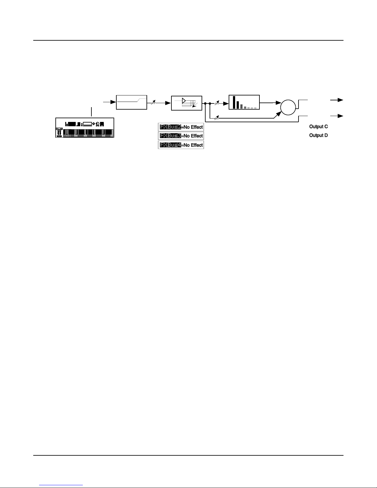
Here’s a diagram of what this studio looks like:
Program
output A
-6dB
EQ
Figure 2-1 Structure of Studio 200*
A More Complex Studio
Press Exit as many times as necessary to get to Program mode. Call up Program 200
ElecPno/Flute. This is a split keyboard program: On Layer 1, which has been assigned to the
KDFX-A outputs, is an electric piano, whose key range goes up to B4. On Layer 2, which goes to
the KDFX-B outputs, is a flute, whose key range starts at C5.
Press the Effects mode button, then the CTRL soft button and set FXCtrl to Master. Then call up
Studio 201 RngMd/PFD/Plt. Press Edit to look inside of this studio.
FXBus1
On the first FXBus is an FX preset called 201*Tut Ring Mod. The algorithm this uses is a ring
modulator, which is a processor that takes the sounds coming into it and combines them with
static waveforms by adding and subtracting their frequencies, thereby creating interesting
nonharmonic effects. Notice that this FX preset uses 1 PAU.
FXBus1
4 Tap BPM
AuxFXBus
Big Chamber
+3.5dB
-4.5dB
Mix
+
Physical
output A
Output B
2-6
EditStudio:FXBUS|Size:1|Free:1|<>FXBus:1
|||||qWWWWT|||||||||||||||||||||||||||||
FX1||kRMod©!!!!!!!!!!!!!!!!!!!!!!!!!!!h|
|||||CVVVVB|||||||||||||||||||||||||||||
FX1:|201*Tut|Ring|Mod|||||||||||||||||||
Wet/Dry|||:90%wet|||||||||||||||||||||||
Out|Gain||:0.0dB||||||||||||Alloc:Auto||
<more||INPUT||FXBUS|||Add|||Remove|more>
As you play on the lower part of the keyboard, the arrow next to FX1 flashes, but as you play on
the upper part it doesn’t. That’s because the upper part of the keyboard (the flute sound) is
routed to a different FXBus.
Bus Overrides
There are two FX preset parameters on this page: Wet/Dry mix and Output Gain. These
parameters actually exist inside the FX preset, and are placed on this page so you can control
them without editing the FX preset itself. These are bus overrides, as described earlier. You can
change both the value of the override parameter and the name of the parameter that shows up in
the bus override: to select a different parameter, simply highlight its name and scroll the Alpha
wheel. As you do so, you will see the other parameters inside the FX preset that can be brought
out to this page.
Page 27

A Tour of KDFX V2
A More Complex Studio
These overrides (that is, which parameters are available, and their values) are stored as part of
the studio, not as part of the FX preset, and therefore you don’t have to create new FX presets
just because you want to change a couple of parameters. There are two bus overrides available
for each of the four insert FXBuses and the Aux bus.
If you don’t want any parameter control on this page, select the parameter’s names, then scroll
the Alpha wheel until you see None.
FXBus2
Press the Chan/Bank Up button to get to FXBus2:
EditStudio:FXBus|Size:2|Free:1|<>FXBus:1
|||||qWWWWT|||||||||||||||||||||||||||||
FX2|!kFDRv©!!!!!!!!!!!!!!!!!!!!!!!!!!!h|
|||||CVVVVB|||||||||||||||||||||||||||||
FX:|202*Flg+Dly145BPM|||||||||||||||||||
Wet/Dry|||:90%wet|||||||||||||||||||||||
Out|Gain||:-2.5dB|||||||||||Alloc:Auto||
<more||INPUT||FXBUS|||Add|||Remove|more>
On this bus is an FX preset called Flg+Dly145BPM, which uses a combination algorithm that
has flanging, delay, and a reverb all rolled into one. The 145BPM part refers to the fact that the
delay times are based on a tempo of 145 BPM,
As you play the flute sound, the arrow next to FX2 flashes, and it keeps on flashing as long as the
various feedback delays are sounding. It doesn’t flash when you play on the lower part of the
keyboard.
This FX preset uses 2 PAUs. Along with the 1 PAU in use on FXBus 1, this makes 3 of the 4
available PAUs accounted for, so the Free parameter has a value of 1.
Press more>, then FXSEND to see that the output configuration of this FXBus has the signal
going to the Aux bus attenuated by -9.5 dB, and going to the main Mix bus at unity gain.
The other two FXBuses are empty, which you can confirm by pressing the Chan/Bank buttons a
few times.
Inputs
Now let’s look at the inputs to the FXBuses. Press <more, followed by the INPUT soft button,
and see this page:
EditStudio:INPUT||||||||||||<>Input:||A|
||||||||||||||||||||||||||||||||||||||y
SP
||||||||||||||||||||||||||||||VVVVVVVV
||||qwwwwwwwtqwwwwwwwtqwwwwww†qwwwwwwtÓ|||||||
||A!kLoShelfgkHiShelfjkFXBus1fONone||g»||||||
||||CVVVVVVVBCVVVVVVVM<>>>>>>S?VVVVVVB
|||G:12.0dB|G:0.0dB||Lvl:0.0d
|||F:370Hz||F:1047Hz|Pan:0%
|||||||||||||||||||||Wid:100%|||||||||||
<more||INPUT||FXBUS||||||||||||||||more>
Input A carries the electric piano, coming from the program’s KDFX-A outputs. Play on the
piano part of the keyboard, and the arrow next to A flashes.
2-7
Page 28

A Tour of KDFX V2
A More Complex Studio
This input is configured to be stereo. It has a large bass boost: 12.0 dB of everything at 370 Hz
and below, which adds a strong low-frequency emphasis to the signal being ring-modulated. Its
signal is being sent only to the first FXBus. The stereo separation (Width) of the signal is at
maximum.
Use the Chan/Bank Up button to go to Input B.
EditStudio:INPUT||||||||||||<>Input:||B|
||||||||||||||||||||||||||||||||||||||y
SP
||||||||||||||||||||||||||||||VVVVVVVV
||||qwwwwwwwtqwwwwwwwtqwwwwww†qwwwwwwtÓ|||||||
||B!kLoShelfgkHiShelfjkFXBus2fONone||g»||||||
||||CVVVVVVVBCVVVVVVVM<>>>>>>S?VVVVVVB
|||G:0.0dB||G:4.0dB||Lvl:0.0dB
|||F:123Hz||F:3136Hz|Pan:0%
|||||||||||||||||||||Wid:100%|||||||||||
<more||INPUT||FXBUS||||||||||||||||more>
This is the flute, coming from the program’s KDFX-B outputs. It is also stereo. The incoming
signal has a strong treble boost on it. It is sent directly to FXBus2 at unity gain and full width.
Play on the flute part of the keyboard, and the arrow next to B flashes.
The other two inputs, C and D, are not assigned to any FXBus.
AuxFX Bus
Now let’s look at the Auxiliary FX Bus (Aux bus). Press more>, then the AUXFX soft button to
look at its page.
EditStudio:AUXFX|Size:3|Free:0||||||||||
||||qWWWWWWWWWWWWWWWWWWWWWW||||qwwwwt|!h
Aux!k203*MedWarmPlate||||||!!!!kMix|g!||
|||||||||||||||||||||||||||||||CVVVVB|||
Wet/Dry|||:100%wet|||||||||||Lvl:0.0dB||
Out|Gain||:0.0dB|||||||||||||Bal:0%|||||
||||||||||||||||||||||||||||||||||||||||
<more||FXSEND|AUXFX||OUTPUT||||||||more>
Here is an FX preset called MedWarmPlate, which is just what it sounds like: a medium-sized,
warm-sounding plate reverb. It has two bus overrides, Wet/Dry mix, and Output Gain. The
Wet/Dry level is set to 100%, because the reverb can be applied to any of this studio’s FXBuses.
You set the actual wet/dry mix for these with the Aux and Mix levels on the FXSEND pages. By
keeping the reverb level on the Aux bus set to 100%, you avoid mixing in a non-reverbed signal
twice.
Since both Insert FXBuses have signal going to the Aux Bus, the arrow next to Aux will flash as
long as any signal processing is going on in either of the insert FXBuses.
2-8
Page 29
A Tour of KDFX V2
A More Complex Studio
Outputs
Finally, press the OUTPUT soft button to get to the OUTPUT page. Here we see that the four
physical output pairs are each passing different parts of the studio. If the outputs are connected
to an external mixer , you can tr eat each of them separately: r ecording them on dif fer ent tracks of
a tape deck, sending them to different outboard processors, or mixing them differently in a
monitor mix.
EditStudio:OUTPUT||||||||||||||||||||||||
Mix|Lvl:0.0dB||||||Output|A:Mix
Mix|Bal:0%|||||||||Output|B:FXBus1
|||||||||||||||||||Output|C:FXBus2
|||||||||||||||||||Output|D:AuxFX
<more||FXSEND|AUXFX||OUTPUT||||||||more>||
Output A has the Mix bus. This is the combined output of the two FXBuses, plus the reverb on
the Aux bus. Its gain and balance are at unity.
Output B has the output of FXBus1, that is, the ring-modulated piano, without any reverb.
Output C has the output of FXBus2, the delayed/flanged/ flute, without any reverb.
Output D has the output of the Aux bus, which is just the reverb signal, with no dry component,
since the value of Wet/Dry on the AUXFX page is 100%.
Note: If you’re using the Mix audio outputs, keep in mind they carry the summed signals of audio
outputs A through D. Normally you would assign each of the audio outputs differently. In the example
above, you might set Outputs B through D to Off, or Output A to Off, to avoid overlapping assignments.
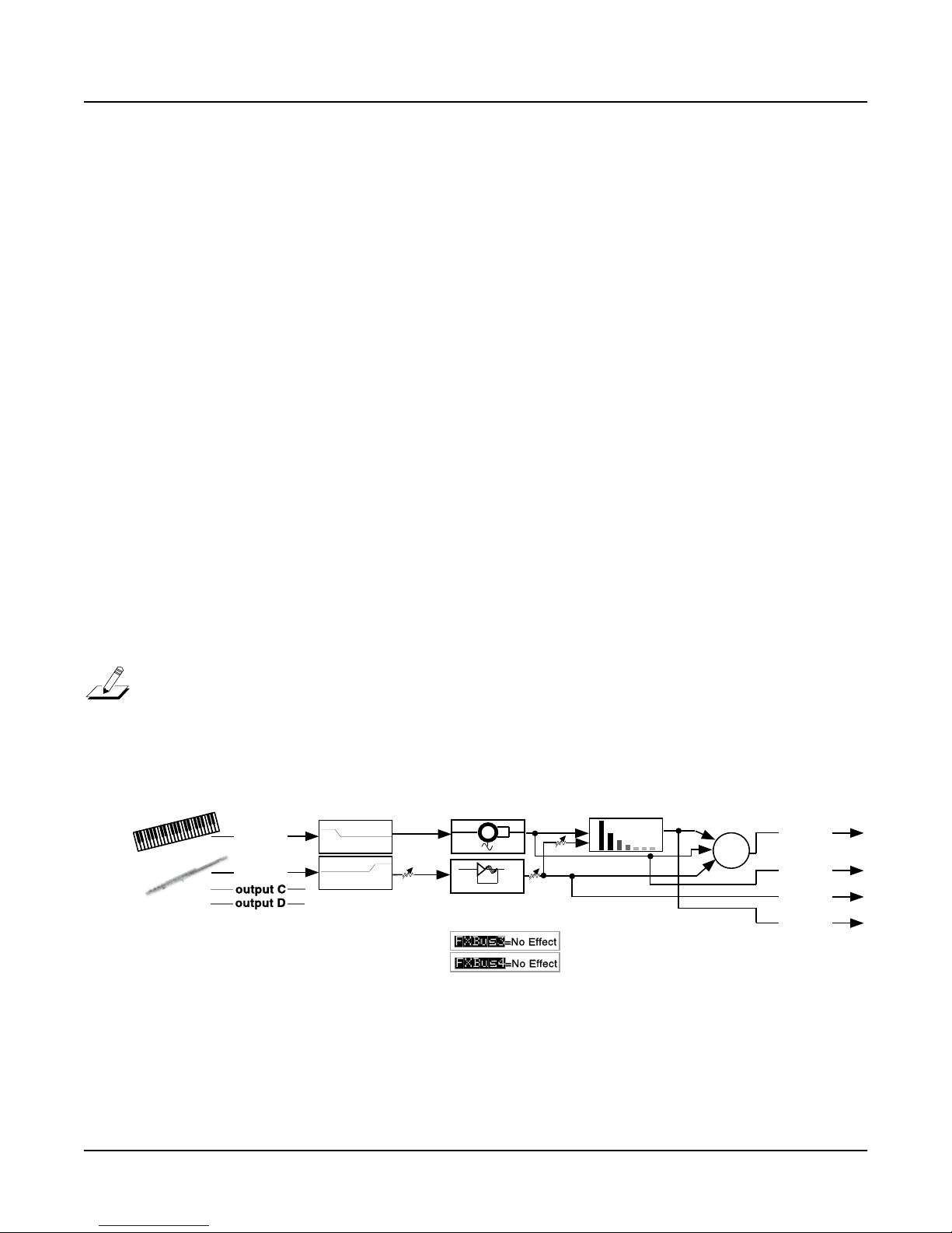
Here is the overall structure for this studio:
AuxFXBus
MedWarmPlate
-9.5dB
Mix
+
Physical
output A
Output B
Output C
Output D
Program
output A
output B
EQs
-5dB
Ptc+Flg+Dly145BP
FXBus1
Tut Ring Mod
FXBus2
-2.5dB
Figure 2-2 Structure of Studio 201
2-9
Page 30

A Tour of KDFX V2
Chaining Effects
Chaining Effects
Now we’ll see how you can employ multiple effects on a single bus using the new chaining
feature in KDFX V2.
Start in Program Mode by highlighting Program 199 Default Program, then pressing the Ef fects
button. From the KDFXMode:MAIN page, select Studio 199 Default Studio (highlight the
Studio name, then scroll through the list or press 1-9-9-Enter on the Alphanumeric pad).
With the Studio name still highlighted, press the Edit button to enter the Studio Editor. As
shown below, you can see that there is an empty effects block on this bus and all 4 PAUs are still
available. If you’d like, you can press the Chan/Bank buttons to see that while there are other
empty blocks (although not on FXBus 4, since it is generally used as a dry bus or a pass-through
to the AUX FX), there are no effects on any of the buses in this studio.
EditStudio:FXBUS|Size:0|Free:4|<>FXBus:1
||||qWWWWT||||||||||||||||||||||||||||||
FX1!k||||©!!!!!!!!!!!!!!!!!!!!!!!!!!!!h|
||||CVVVVB||||||||||||||||||||||||||||||
FX:|199|No|Effect|||||||||||||||||||||||
None||||||:|||||||||||||||||||||||||||||
None||||||:|||||||||||||||||Alloc:Auto||
<more||INPUT||FXBUS|||Add|||Remove|more>
Now press the Add soft button to add another empty effects block to this bus:
EditStudio:FXBUS|Size:0|Free:4|<>FXBus:1
||||qwwwwt|||qWWWWT|||||||||||||||||||||
FX1!k||||g!!!k||||©!!!!!!!!!!!!!!!!!!!h|
||||CVVVVB|||CVVVVB|||||||||||||||||||||
FX:|0|None||||||||||||||||||||||||||||||
None||||||:|||||||||||||||||||||||||||||
None||||||:|||||||||||||||||Alloc:Auto||
<more||INPUT||FXBUS|||Add|||Remove|more>
We’ll use a distortion preset for the first effect in this block. Use the cursor keys to highlight the
first effects block, then select Preset 763 SubtleDistortion:
EditStudio:FXBUS|Size:1|Free:3|<>FXBus:1
||||qWWWWT|||qwwwwt|||||||||||||||||||||
FX1!kDist©!!!k||||g!!!!!!!!!!!!!!!!!!!h|
||||CVVVVB|||CVVVVB|||||||||||||||||||||
FX:|763|SubtleDistortion||||||||||||||||
Wet/Dry|||:100%wet||||||||||||||||||||||
Out|Gain||:-24.0dB||||||||||Alloc:Auto||
<more||INPUT||FXBUS|||Add|||Remove|more>
You can see that the effects block now displays an abbreviation that indicates the type of effect,
while the lines below show the name of the specific effect preset, as well as the bus overrides
defined for this preset. As always, you can select one of the bus overrides and change it to be any
parameter of the effect’s underlying algorithm. You’ll probably want to keep the two overrides
here, however, since they offer useful control over the preset: Wet/Dry lets you quickly adjust
how much of the signal is effected, while Out Gain lets you boost or cut the audio level of this
effect as it enters the next effect in the chain.
2-10
Page 31

A Tour of KDFX V2
Chaining Effects
We’ll now add phaser and reverb effects to the chain:
Use the cursor keys to highlight the second effects block, then select Preset 191 Slow Deep
Phaser:
EditStudio:FXBUS|Size:1|Free:2|<>FXBus:1
||||qwwwwt|||qWWWWT|||||||||||||||||||||
FX1!kDistg!!!kPhsr©!!!!!!!!!!!!!!!!!!!h|
||||CVVVVB|||CVVVVB|||||||||||||||||||||
FX:|191|Slow|Deep|Phaser||||||||||||||||
Notch/Dry|:50%wet|||||||||||||||||||||||
None||||||:|||||||||||||||||Alloc:Auto||
<more||INPUT||FXBUS|||Add|||Remove|more>
Press Add again to add another effects block. If the “Out of ef fect blocks” message displays (and
it should), then you’ll have to remove an effects block from one of the other buses in this studio.
Press the Chan/Bank up button to display the screen for FXBus 2; you will see an empty effects
block, highlighted for your convenience; press the Remove soft button and that block (that you
weren’t using anyway) is now available for you on FXBus 1.
Press the Chan/Bank down button to return to FXBus 1. Use the cursor keys to highlight the
Phsr block, then press the Add soft button. This time an empty effects block will be added to the
chain for you. Note that the new block is added to the right of the current block, which is why
we highlighted the Phsr block before pressing Add.
While the third block in the chain (the one you just added) is highlighted, select Preset 104 Cool
Dark Place. Your display will look something like this:
EditStudio:FXBUS|Size:3|Free:2|<>FXBus:1
||||qwwwwt|||qwwwwt|||qwwwwt||||||||||||
FX1!kDistg!!!kPhsrg!!!kRvrbg!!!!!!!!!!h|
||||CVVVVB|||CVVVVB|||CVVVVB||||||||||||
FX:|104|(Cool|Dark|Place)|||||||||||||||
In/Out||||:In|||||||||||||||||||||||||||
Out|Gain||:-0.5dB|||||||||||Alloc:Auto||
<more||INPUT||FXBUS|||Add|||Remove|more>
The outlined box around the effect block and the parentheses around the preset name indicate
that we’ve chosen an effect that requires more processing power than we currently have
available in this studio. Take a quick glance at the top line of the screen and the problem
becomes obvious: Cool Dark Place wants 3 PAUs (as shown by the Size parameter) but only 2
are available (as shown by the Free parameter). KDFX will still let you place the preset on the
chain, but it won’t be active, so you won’t hear the effect on your signal.
Let’s see if we can find a reverb that fits in this chain. Press the + cursor button once to have a
look at the next listed preset, 105 Gunshot Verb:
EditStudio:FXBUS|Size:2|Free:0|<>FXBus:1
||||qwwwwt|||qwwwwt|||qWWWWT||||||||||||
FX1!kDistg!!!kPhsrg!!!kDlyR©!!!!!!!!!!h|
||||CVVVVB|||CVVVVB|||CVVVVB||||||||||||
FX:|105|Gunshot|Verb||||||||||||||||||||
In/Out||||:In|||||||||||||||||||||||||||
Out|Gain||:-0.5dB|||||||||||Alloc:Auto||
<more||INPUT||FXBUS|||Add|||Remove|more>
As you can see, this effect requires 2 PAUs, which is what happens to be available in the Studio.
If you decide to use this effect, however, you will not be able to add any more presets to this
2-11
Page 32

A Tour of KDFX V2
Chaining Effects
chain, since you have now maximized your PAU usage. If you’d like to have four effects on the
chain, you’ll have to select only effects that use a single PAU. (You’ll also have to remove the
empty effects block from FXBus 3 so that it will be available for FXBus 1.) Keep in mind,
however, that you can still send the output of this chain to an effect on the Aux bus, which
allows effects using up to 3 PAUs.
Now let’s audition this effects chain: play your keyboard to hear the sound of the 199 Default
Program running through the 3 effects you’ve chosen in series.
To use this effects chain with any other program, you’ll have to save the studio. Press Exit, then
Rename. Enter a name for the studio, then press OK. The save dialog now offers you the next
available studio number; you can save the studio at this location or choose a different one. Press
Save and you are returned to the KDFXMode:MAIN page. Press Exit to r eturn to ProgramMode.
You can now select a program, press Edit, followed by the KDFX soft button (you’ll have to
press one of the more soft buttons a few times to bring the KDFX soft button into view), and
select your new studio for the program’s effects. Don’t forget to check the program’s OUTPUT
page to be sure that its output pair is routed to KDFX-A.
2-12
Page 33

A Complex Studio with Real-Time Control
A Complex Studio with Real-Time Control
The final studio we’ll look at is a bit more complex, not least because it’s under real-time contr ol.
Getting real-time control of a studio requires doing some advance work. Most noticeably, you
have to create a program or setup that uses a particular studio, then define a set of FXMods in
that program or setup. The FXMods provide the settings that link physical controllers such as
sliders to studio effects like wet/dry mix.
For all of this to work, the FXCtrl parameter on the KDFXMode:CTRL page must be set to a
value of Program (if you want only programs to be in charge of studio selection and controls) or
Setup (if you want only setups to have this ability)—or Auto if you want to control over studios
whenever you select a program or a setup.
In this example, we’ll work with setup control over a studio—the procedure for working with
program control is almost exactly the same.
Setting the FXCTRL
To enable real-time control of the studio from the setup, we have to put the K2600/K2500 in the
correct Effects mode. Go to the KDFXMode:CTRL page (press Effects followed by the CTRL soft
button), and set FXCtrl to Setup. FX Channel automatically goes to None.
KDFXMode:CTRL||||FXCtrl:Auto||||<>Enable
Studio:199|Default|Studio|||||||||||
FXCtrl:Setup|||||||||||||||||||||||||||||
FXChan:None|||||||||||||||||||||||||||||
||||||||||||||||||||||||||||||||||||||||
||||||||||||||||||||||||||||||||||||||||
Dither:Medium|||||||||||||||||||||||||||
MAIN||CTRL|||EQBYP||FXBYP||BUSMUT|BypAll
A Tour of KDFX V2
The Setup
Now let’s look at the setup that we’re going to use to control our studio. Press Setup to go into
Setup mode, and select 200 KDFXCombo.
This is a four-zone setup, with bass and drums at the bottom, electric piano in the middle, and a
breathy flute-like sound on the top. Each layer goes to a separate KDFX output pair, so they can
all get different processing.
If you edit the setup and look at the various zones, you’ll see this:
• Zone 1: Gtr Jazz Band, a layered bass and drum program, going to KDFX-A.
• Zone 2: Dual Slap Bass, also going to KDFX-A. This and the previous zone are active from
the bottom of the keyboard up to A3.
• Zone 3: Pno & Epno & Pad, an electric piano and pad program, going to KDFX-B, which is
active from A#3 to F#5.
• Zone 4: Hybrid Vox, going to KDFX-C, and active from G5 and up.
2-13
Page 34

A Tour of KDFX V2
A Complex Studio with Real-Time Control
Looking at the Studio
Starting from SetupMode, press Edit, then more> three times. Now press the KDFX soft button
to view the studio. The name of the studio associated with this setup, 202*Complex, appears.
EditSetup:KDFX||||||||||||||||All|Zones||
Studio:202*Complex||||||||||
Bus:|Param:|||||Adjust:||Source:||Depth:
FX1||In/Out|||||Out||||||SoftPd|||1
FX1||Aux|Lvl||||-55.0dB||MIDI27|||52dB
FX2||L|Fdbk|Lvl|0%|||||||MIDI26|||100%
<more||KDFX|||FXMOD2|FXMOD3|FXMOD4|more>
Highlight the studio’s name and press Edit, and let’s dig into this studio.
Press INPUT if you’d like to look at the EditStudio:INPUT pages. These are all set up
straightforwardly, with Input A going to FXBus1, Input B going to FXBus2, etc. Press the
Chan/Bank buttons to move between the input groups.
On the FXBus Pages
Press FXBUS to look at the FXBuses. On FXBus1 is 205*CompresHK, a hard-knee compressor.
EditStudio:FXBus|Size:1|Free:1|<>FXBus:1
|||||qWWWWT|||||||||||||||||||||||||||||
FX1|!kCmpr©!!!!!!!!!!!!!!!!!!!!!!!!!!!h|
|||||CVVVVB|||||||||||||||||||||||||||||
FX:|205*CompresHK|||||||||||||||||||||||
In/Out||||:FXMod||||||||||||||||||||||||
None||||||:||||||||||||||||Alloc:Auto|||
<more||INPUT||FXBUS|||Add||Remove||more>
The In/Out parameter shown on this page is a bus override, similar to the ones we’ve seen in
earlier tutorials. However, instead of saying In or Out it says FXMod. This means that this
parameter isn’t controlled from inside the studio at all—it’s controlled by something outside the
studio.
As it happens, it’s controlled by the soft pedal, MIDI Controller 67—Switch Pedal 3 for
K2600/K2500 keyboard users. We’ll see how this is done in a moment. Pressing this pedal
causes the compressor to kick in, squashing the dynamic range of the sound. The MakeUpGain
inside the compressor is set to 6.0 dB, however, so the level doesn’t change much when the
compressor is engaged.
Such control is useful on this program, which uses velocity-switching to change drum sounds.
As you play harder , the dr um sounds change, but they also get louder, which you may not want.
With the compressor engaged, the drum sounds can change without getting louder.
There’s another FXMod, which is assigned to the Aux bus send level; this is indicated on the
EditStudio:FXSEND page (press more> followed by the FXSEND soft button to have a look). On
the Aux bus is a reverb, so this FXMod controls how much of the signal coming through here
will go to the reverb. It’s under the control of Slider G, MIDI Controller 27. Play the bass and
drums and move that slider, and you’ll hear the reverb go in and out.
2-14
Page 35

A Tour of KDFX V2
A Complex Studio with Real-Time Control
Setting Up FXMods
How do you set up FXMods? That’s back on the KDFX page in the Setup Editor. Exit the Studio
Editor (if you have made any changes, don’t save them—that will only confuse things!), then
press the KDFX soft button. Listed here are the FXMods for this setup:
EditSetup:KDFX||||||||||||||||All|Zones||
Studio:202*Complex||||||||||
Bus:|Param:|||||Adjust:||Source:||Depth:
FX1||In/Out|||||Out||||||SoftPd|||1
FX1||Aux|Lvl||||-55.0dB||MIDI27|||52dB
FX2||L|Fdbk|Lvl|0%|||||||MIDI26|||100%
<more||KDFX|||FXMOD2|FXMOD3|FXMOD4|more>
The first FXMod affects the signal on the FX1 bus, as shown by the Bus parameter. Param
indicates which parameter is affected on the FX1 bus—in this case, the In/Out parameter. The
Adjust parameter defines the initial condition of the parameter controlled on this bus—in this
case, the In/Out parameter has an initial value of Out (disengaged).
The Source parameter determines what MIDI Controller affects the In/Out parameter. For the
first FXMod it’s SoftPd (that’s MIDI 67, which is Soft Pedal according to the MIDI specification,
and which the K2600/K2500 uses as the default destination for Switch Pedal 3). While this setup
is current, any K2600/K2500 controller—be it a wheel, slider, ribbon, or button—that’s
programmed to send MIDI 67 will affect the In/Out parameter on the FX1 bus of this studio.
The Depth parameter defines how much the soft pedal affects the In/Out value, and here it is 1.
For parameters with binary value, likes In/Out or On/Off, the Depth parameter can have only
three values: 1, 0, or -1. If it is set to 1 or -1, then changing the state of the Source (in this case,
depressing the soft pedal), changes the parameter’s state—in this case, going from Out to In. (If
it’s set to 0, then the Source has no effect on the value of the parameter.)
Now look at the second FXMod. It sets the Aux Lvl on the FX1 bus to an initial value -55 dB. The
Source, MIDI 27, can raise that level by as much as 52 dB, to put it at -3 dB. You can hear this in
action when you move Slider G (which defaults to MIDI 27) while you play this patch.
FXBus 2
Let’s go back into the Studio Editor and look at FXBus 2. Highlight the studio name on the
EditSetup:KDFX page, then press Edit; then press the upper Chan/Bank button to change buses.
Here’s our piano and string pad, going through an FX preset called 206*Fast&RichChorus.
EditStudio:FXBus|Size:1|Free:1|<>FXBus:2
|||||qWWWWT|||||||||||||||||||||||||||||
FX2|!kChor©!!!!!!!!!!!!!!!!!!!!!!!!!!!h|
|||||CVVVVB|||||||||||||||||||||||||||||
FX:|206*Fast&RichChorus|||||||||||||||||
None||||||:|||||||||||||||||||||||||||||
None||||||:|||||||||||||||||Alloc:Auto||
<more||INPUT||FXBUS|||Add|||Remove|more>
2-15
Page 36

A Tour of KDFX V2
A Complex Studio with Real-Time Control
If you now go inside the FX Preset (by pressing Edit), you’ll see that the left and right feedback
levels (“Fdbk Lvl”) are under FXMod control:
EditFXPreset:PARAM1|||||||EffectSize:1/1
FXAlgorithm:152|Dual|Chorus|1|
||||||||||||||||||||In|Gain|||:0.0dB
L|Wet/Dry|:50%wet|||R|Wet/Dry|:50%wet
L|Out|Gain:0.0dB||||R|Out|Gain:0.0dB
L|Fdbk|Lvl:FXMod||||R|Fdbk|Lvl:FXMod
Xcouple|||:0%|
<more||PARAM1|PARAM2|PARAM3||||||||more>
Press PARAM2, you’ll see that the Left and Right LFO Rates are also under FXMod control.
EditFXPreset:PARAM2|||Dual|Chorus|1|||||
L|Tap|Lvl|:75%||||||R|Tap|Lvl|:75%|
L|Tap|Pan|:-100%||||R|Tap|Pan|:100%
L|LFO|Rate:FXMod||||R|LFO|Rate:FXMod
L|LFODepth:5.0ct||||R|LFODepth:5.0ct
L|Tap|Dly|:4.0ms||||R|Tap|Dly|:4.0ms
L|HF|Damp|:25088Hz||R|HF|Damp|:25088Hz
<more||PARAM1|PARAM2|PARAM3||||||||more>
Go back out of the FXPreset and the Studio, to the Setup’s KDFX page, by pressing Exit twice.
Here we see that on FX Bus 2, L Fdbk Lvl has a starting value of 0%, and can be changed, using
MIDI controller 26 (Slider F), up to 100%.
Press FXMOD2 to go to the next page of FXMods, and you’ll see the same slider changing the R
Fdbk Lvl, only in this case the Depth is -100%, meaning the feedback on this channel will be out
of phase with the main signal.
EditSetup:FXMOD2||||||||||||||All|Zones||
Bus:|Param:|||||Adjust:||Source:||Depth:
FX2||R|Fdbk|Lvl|0%|||||||MIDI26|||-100%
FX2||L|LFO|Rate||0.50Hz||MIDI25|||8.25H
FX2||R|LFO|Rate||0.52Hz||MIDI25|||8.25H
FX2||Aux|Lvl||||-15.5dB||MIDI27|||15dB
FX3||Fdbk|Level|10%||||||MIDI24|||89%
<more||KDFX|||FXMOD2|FXMOD3|FXMOD4|more>
Further down the FXMOD2 page are the assignments to the LFO rates: MIDI controller 25
(Slider E) is assigned to the left and right LFO1 Rates, with minimum values of 0.50 and 0.52
Hz, respectively, and maximum change of 8.25 Hz. Set the feedback level high and you can
really clearly hear the LFO rate changing (but watch out that the effect doesn’t go into
oscillation at the highest feedback level).
Finally, MIDI Controller 27, our old friend Slider G, controls the Aux Level send on this bus as
well, controlling the amount of this signal that will be sent to the Aux reverb, and thus how
much reverb will be applied to the piano/pad sounds. As you can see, you can assign a single
Source to multiple FXMods.
2-16
Page 37

A Tour of KDFX V2
A Complex Studio with Real-Time Control
FXBus 3
Press Edit, then use the Chan/Bank buttons to select FXBus 3. Here’s where our breathy flute
sound is, and it’s going through a delay FXPreset called 207*Adj Delay.
EditStudio:FXBus|Size:1|Free:1|<>FXBus:3
|||||qWWWWT|||||||||||||||||||||||||||||
FX3|!kDly|©!!!!!!!!!!!!!!!!!!!!!!!!!!!h|
|||||CVVVVB|||||||||||||||||||||||||||||
FX:|207*Adj|Delay|||||||||||||||||||||||
Wet/Dry|||:50%wet||||||||||||||||||||||||
Out|Gain||:0.0dB||||||||||||Alloc:Auto||
<more||INPUT||FXBUS|||Add|||Remove|more>
Press Edit to inside the FXPreset, and you’ll see that the Feedback Level is under FXMod
control.
EditFXPreset:PARAM1|||||||EffectSize:1/1
FXAlgorithm:131|4-Tap|Delay|
||||||||||||||||||||In|Gain|||:0.0dB
Wet/Dry|||:50%wet|||Out|Gain||:0.0dB
Fdbk|Level:FXMod
||||||||||||||||||||Dry|Bal|||:0%
HF|Damping:25088Hz||Hold||||||:Off|
<more||PARAM1|PARAM2|PARAM3||||||||more>
Press PARAM2, and on that page, you’ll see that Delay Scale is also under FXMod control:
EditFXPreset:PARAM2|||||4-Tap|Delay|||||
Loop|Crs||:480ms|||||
||||||||||||||||||||DelayScale:FXMod|
Loop|Fine|:0.0ms
Tap1|Crs||:120ms||||Tap3|Crs||:360ms|
Tap1|Fine|:0.0ms||||Tap3|Fine|:10.0ms|
Tap2|Crs||:240ms||||Tap4|Crs||:480ms|
Tap2|Fine|:5.0ms||||Tap4|Fine|:-5.0ms|
<more||PARAM1|PARAM2|PARAM3||||||||more>
Go back out to the Setup (press Exit twice), press the FXMOD3 soft button, and look at the
FXMOD3 page.
EditSetup:FXMOD3||||||||||||||All|Zones||
Bus:|Param:|||||Adjust:||Source:||Depth:
FX3||DelayScale||0.54x|||Foot||||||6.00x
FX3||Aux|Lvl||||-50.0dB||MIDI27|||52dB
None|None||||||||||||||||OFF
None|None||||||||||||||||OFF
None|None||||||||||||||||OFF
<more||KDFX|||FXMOD2|FXMOD3|FXMOD4|more>
On the FXMOD3 page, we see that the Delay Scale, which scales all of the various delays in the
Algorithm, is controlled by the Foot Pedal, MIDI controller 4—Control Pedal 1 for
K2600/K2500 keyboard users. The delay is nominally a 480 ms loop, with four equal-spaced
taps inside it, 120 ms apart. With the Foot Pedal, we can scale all those times by a factor of
between 0.54 and 6.00.
Finally, the Aux Level from this bus, controlling another reverb send, is once again assigned to
MIDI controller 27, Slider G.
2-17
Page 38

A Tour of KDFX V2
A Complex Studio with Real-Time Control
And in Conclusion...
Here’s a summary of the FXMods in our complex studio with real-time control:
• Soft pedal puts compression on the bass and drums.
• Slider F controls the feedback on the chorus on the piano/string pad. Slider E controls the
LFO speed on that chorus.
• Slider D controls the feedback on the delay on the breathy flute.
• Foot Pedal controls the delay time on the breathy flute.
• Slider G controls the reverb send for all three zones.
2-18
Page 39

A Note About Effects in Setups
This applies primarily to K2600R/K2500R users who are playing their units with a conventional
MIDI keyboard. In order to play setups, which normally require a multi-zoned/multichannel
keyboard like the K2600 or PC2, the K2600R/K2500R includes a parameter called Local
Keyboard Channel (LocalKbdCh), found on the MIDI Mode RECEIVE page. If you set this
parameter to the transmitting channel of the keyboard, then the K2600 takes all incoming MIDI
data on that channel and treats it as if it was coming from a local keyboard—that is, it plays all
the zones in the setup.
However, when you use this feature, the K2600 will respond to certain MIDI Controller
messages coming in on this channel only if the Controller has been specified as a destination on
the controller assignment pages in the setup (SLIDER, SLID/2, etc.)—and then, only if the setup
assigns the customary physical controller to that MIDI Controller.
For example, Slider A is customarily assigned to Data (MIDI Controller 6), but if on the setup’s
SLIDER page, Slider A has been reassigned to something else, then Data messages coming from
the external keyboard on the local keyboard channel will not be recognized. Therefore, any
MIDI Controller message that is not in its customary place in the setup cannot be used as a
KDFX Source, because the setup will not recognize it. A list of the physical controllers affected
by using the local keyboard channel is included in the MIDI Mode chapter of your K2600/K2500
Musician’s Guide.
A Tour of KDFX V2
A Note About Effects in Setups
This is not an issue in Program mode, or when using the K2600/K2500 with a sequencer. In
those cases the LocalKbdCh should be set to None, and there is no restriction on the MIDI data
passing through.
2-19
Page 40

A Tour of KDFX V2
Building Y our Own
Building Y our Own
Now that we’ve walked you through a complex studio, here are some hints on how to go about
building your own.
First, you want to decide whether you want the studio to be static, or to be dynamic under
FXMod control from the K2600/K2500 keyboard and/or an external MIDI source. If it’s to be
static, the value of FXCtrl must be Master, while if it’s to be dynamic, the value of FXCtrl must
be Program, Setup, or Auto, depending on how you want to approach it.
Then you need to look at how your program outputs are arranged, so you can design the studio
intelligently. If you’re using internal setups, look at the output assignments on the various
zones, and change them so sounds that need different effects are separated, and those that can
use the same effects are grouped. If you’re using a MIDI sequencer, you might want to use the
Channel output overrides in MIDI Mode, and arrange your sequence so that the assignment of
tracks to FXBuses is determined by the tracks’ MIDI channel assignments.
Now set up your studio, assigning FX presets to the program outputs/KDFX inputs. Many of
the ROM studios follow a common organizational plan, which might be a good starting point
for your studios:
• FXBus 1 contains a relatively simple reverb with a low Size requirement.
• FXBus 2 contains an effect that does not increase the “length” of the sound (that is, no reverb
or delay), something like chorus, flange, phaser, distortion, shaper, pitcher, enhancer , EQ, or
EQ morpher.
• FXBus 3 contains effects that take up lots of time, such as delays, delays with reverb, or
other “Lead” sounds.
• FXBus 4 is dry, since the first three FXBuses have probably used up all the PAUs.
• The AUXFX Bus contains a larger reverb (Size: 2 or 3), a compressor, or a graphic EQ. It can
often be used instead of an FXBus reverb, such as the one on FXBus1. If you use it in this
way (set the Aux Lvl on FXBus 1 to 0dB or higher), it frees up FXBus1 for use as an
Enhancer, Stereo Image, Flanger, etc.
Finally, set up your FXMods in the setup or program you plan to use. If you’re using a
sequencer , you might want to dedicate a pr ogram just to the studio and FXMods, with no sound
coming from that program.
Keep in mind that FXMods don’t always have to be dynamic—they can be used to assign static
(Source: OFF) values to the parameters in a studio that are different from the studio’s normal
parameters. This lets you create and store multiple variations on a studio without making each
one a separate studio—when you want to call up the variation, merely call up the program that
contains the correct FXMods.
One last reminder: don’t forget to save your studio!
2-20
Page 41

Chapter 3
Algorithm Reference
This chapter provides complete reference information for the new algorithms included in KDFX
V2. This information is in addition to the algorithm information provided in Chapter 10 of your
K2600 Musician’s Reference or your K2500 KDFX Algorithm Reference.
Algorithm Reference
3-1
Page 42

Algorithm Reference
Degen Regen BPM
138 Degen Regen BPM
Long delay allowing loop instability
PAUs: 4 each
Degen Regen BPM starts as a simple mono delay line with feedback. However with the Fdbk Gain and
Dist Drive parameters, the algorithm can be pushed hard into instability. When Degen Regen BPM is
unstable, your sound gets a little louder on each pass through the delay line. Eventually the sound will hit
digital clipping when the effects processor runs out of headroom bits. To keep this all under control, a softknee compressor has been included inside the delay line loop. With the compressor properly set, the
sound never reaches digital clipping, but it does become more and more distorted as it gets pushed har der
and harder into the compressor. To make things really nasty, there’s also a distortion in the delay path.
(The distortion parameters are on the PARAM4 page with the compressor parameters.)
Degen Regen BPM uses all 4 PAUs available for insert effects. With the resources of all 4 PAUs available,
Degen Regen BPM lets you set the longest mono delay line available in KDFX which is just over 20
seconds. If you want a long delay, this is the algorithm to do it. (You don’t have to over-drive the feedback
or use the distortion.)
The delay has two output taps in addition to the feedback tap. Each tap may be moved along the delay line
using an LFO (internal to the effects processor). The output taps have separate controls for level and
panning (in the stereo configurations).
Throw a few filters into the delay line loop, and you get a pretty versatile delay line. The available filters
are highpass (LF Damping), lowpass (HF Damping), bass shelf, treble shelf, and two parametric EQs
(Mid1, Mid2).
For details about the compressor see the documentation for SoftKneeCompress. For the distortion see the
documentation for Mono Distortion.
3-2
Page 43

L Input
t
Level
Level
Algorithm Reference
Degen Regen BPM
Dry
L Output
Pan
Wet
Pan
R Outpu
Delay
R Input
Feedback
Compressor Distortion Filters
Dry
Figure 1 Degen Regen BPM
Parameters:
Page 1
Wet/Dry -100 to 100%wet Out Gain Off, -79.0 to 24.0 dB
Loop Gain Off, -79.0 to 24.0 dB Tempo System, 1 to 255 BPM
Loop Lvl -100 to 100% Send Gain Off, -79.0 to 24.0 dB
HF Damping 8 to 25088 Hz LF Damping 8 to 25088 Hz
Page 2
LoopLength 0 to 32 bts Mid1 Gain -79.0 to 24.0 dB
LFO Period 1/24 to 32 bts Mid1 Freq 8 to 25088 Hz
Bass Gain -79.0 to 24.0 dB Mid1 Width 0.010 to 5.000 oct
Bass Freq 8 to 25088 Hz Mid2 Gain -79.0 to 24.0 dB
Treb Gain -79.0 to 24.0 dB Mid2 Freq 8 to 25088 Hz
Treb Freq 8 to 25088 Hz Mid2 Width 0.010 to 5.000 oct
3-3
Page 44

Algorithm Reference
Degen Regen BPM
Page 3
LpLFODepth 0.0 to 230.0 ct Tap1 Delay 0 to 32 bts
LpLFOPhase 0.0 to 360.0 deg Tap1 Level 0 to 100 %
T1LFODepth 0.0 to 230.0 ct Tap1 Pan -100 to 100%
T1LFOPhase 0.0 to 360.0 deg Tap2 Delay 0 to 32 bts
T2LFODepth 0.0 to 230.0 ct Tap2 Level 0 to 100 %
T2LFOPhase 0.0 to 360.0 deg Tap2 Pan -100 to 100%
Page 4
Comp Atk 0.0 to 228.0 ms Comp Ratio 1.0:1 to 100.0:1, Inf:1
Comp Rel 0 to 3000 ms Comp Thres -79.0 to 0.0 dB
CompSmooth 0.0 to 228.0 ms Dist Drive 0 to 96 dB
DistWarmth 8 to 25088 Hz
|||||||||||||||||||||||||||||| Reduction
-dB 40 20 12 8 6 4 2 0
Wet/Dry The relative amount of input signal and delay signal that is to appear in the final effect
output mix. When set to 0%, the output is taken only from the input (dry). When set to
100%, the output is all wet.
Out Gain The overall gain or amplitude at the output of the effect.
Send Gain The input gain or amplitude to the Degen Regen BPM delay loop.
Loop Gain Controls the signal level of the signal which is fed back to the input of the delay line. If
other elements of Degen Regen BPM were removed (set flat), then Loop Gain would
cause the algorithm to become unstable above 0 dB. However other parameters interact
resulting in a more complex gain structure. See also Loop Lvl.
Loop Lvl A convenience parameter which may be used to reduce the Fdbk Gain feedback strength.
It may be helpful if you are used to dealing with feedback as a linear (percent) control. At
100%, the feedback strength is as you have it set with Loop Gain. Lower levels reduce the
feedback signal, so at 50% the feedback signal is reduced by -6 dB from the selected Loop
Gain level. Negative values polarity invert the feedback loop signal.
Tempo In Degen Regen BPM, Tempo is the basis for the delay lengths, as referenced to a musical
tempo in bpm (beats per minute). When this parameter is set to System, the tempo is
locked to the internal sequencer tempo or to incoming MIDI clocks. In this case, FXMods
(FUNs, LFOs, ASRs etc.) will have no effect on the Tempo parameter.
LF Damping The -3 dB frequency in Hz of a one-pole highpass filter (6 dB/octave) placed in the
feedback path of the delay line. The signal does not go through the filter the first time
through the delay line. Multiple passes through the feedback will cause the signal to
become more and more bright (removing low frequencies).
HF Damping The -3 dB frequency in Hz of a one-pole lowpass filter (-6 dB/octave) placed in the
feedback path of the delay line. The signal does not go through the filter the first time
through the delay line. Multiple passes through the feedback will cause the signal to
become more and more dull.
3-4
Page 45

Algorithm Reference
Degen Regen BPM
LoopLength The delay length of the feedback tap. If feedback is turned up from 0%, this parameter sets
the repeating delay loop length. In Degen Regen BPM, the loop length is specified as a
fraction or multiple of the tempo, in “beats.” The length of a delay loop in seconds can be
calculated from beats as T = (beats/tempo) ❃ 60.
LFO Period The feedback tap and the output taps lengths can be modulated with an LFO internal to
the effects processor. The rate at which the tap positions move are tied to a common
period control (time for one complete cycle) which is expressed in beats. The LFO Period
control is specific to Degen Regen BPM. The depth of modulation is specified by the
LpLFODepth parameter. Frequency in Hz can be calculated from the period in beats as
F = tempo/(beats ❃ 60). Since this moving delay tap is part of the feedback path through
the delay, subsequent passes of the signal through the delay may result in some strange
pitch modulations. It is possible to set LFO Period with LoopLength so that alternate
passes through the loop detune then retune the signal (for example, set the LFO period to
double the LoopLength). The maximum pitch shift up is not identical to the maximum
pitch shift down, so the alternating detune/retune effect is not perfect.
Bass Gain The amount of boost or cut in dB that the bass shelving filter should apply to the low
frequency signal components. Every increase of 6 dB approximately doubles the
amplitude of the signal. Positive values boost the bass signal below the specified
frequency. Negative values cut the bass signal below the specified frequency. Since the
filters are in the delay feedback loop, the cut or boost is cumulative on each pass the
sound makes through the loop.
Bass Freq The center frequency of the bass shelving filter in intervals of one semitone.
Treb Gain The amount of boost or cut in dB that the treble shelving filter should apply to the high
frequency signal components. Every increase of 6 dB approximately doubles the
amplitude of the signal. Positive values boost the treble signal above the specified
frequency. Negative values cut the treble signal above the specified frequency. Since the
filters are in the delay feedback loop, the cut or boost is cumulative on each pass the
sound makes through the loop.
Treb Freq The center frequency of the treble shelving filter in intervals of one semitone.
Midn Gain The amount of boost or cut in dB that the parametric filter should apply to the specified
signal band. Every increase of 6 dB approximately doubles the amplitude of the signal.
Positive values boost the signal at the specified frequency. Negative values cut the signal
at the specified frequency. Since the filters are in the delay feedback loop, the cut or boost
is cumulative on each pass the sound makes through the loop.
Midn Freq The center frequency of the parametric EQ in intervals of one semitone. The boost or cut
will be a maximum at this frequency.
Midn Width The bandwidth of the parametric EQ may be adjusted. You specify the bandwidth in
octaves. Small values result in a very narrow (high-Q) filter response. Large values result
in a very broad response.
LpLFODepth The feedback (loop) delay tap will have its position modulated by an LFO (internal to the
FX processor) if the LpLFODepth parameter is non-zero. A moving tap on a delay line will
result in a pitch shift, and LpLFODepth sets the maximum pitch shift (up and down) in
cents.
LpLFOPhase Specifies the phase angle of the feedback (loop) LFO relative to the output tap LFOs and
the system (or MIDI) tempo clock, if turned on (see Tempo). For example, if one LFO is set
to 0° and another is set to 180°, then when one LFO delay tap is at its shortest, the other
will be at its longest. If the system (or MIDI) tempo clock is turned on , the LFOs are
synchronized to the clock with absolute phase.
3-5
Page 46

Algorithm Reference
Degen Regen BPM
TnLFODepth The output delay taps (1 and 2) will have their positions modulated by an LFO (internal to
TnLFOPhase Specifies the phase angle of the output LFO tap (1 or 2) relative to the other output LFO
Tapn Delay The delay length of the output tap 1 or 2. In Degen Regen BPM, the tap length is specified
Tapn Level The level of the output tap 1 or 2 expressed as a percent.
Tapn Pan The output taps 1 and 2 are mono sources that can be panned to the left or right output
Comp Atk The time for the compressor to start to cut in when there is an increase in signal level
Comp Rel The time for the compressor to stop compressing when there is a reduction in signal level
the FX processor) if the TnLFODepth parameter is non-zero. A moving tap on a delay line
will result in a pitch shift, and TnLFODepth sets the maximum pitch shift (up and down)
in cents.
tap, the feedback (loop) LFO tap, and the system (or MIDI) tempo clock, if turned on (see
Tempo). For example, if one LFO is set to 0° and another is set to 180°, then when one LFO
delay tap is at its shortest, the other will be at its longest. If the system (or MIDI) tempo
clock is turned on, the LFOs are synchronized to the clock with absolute phase.
as a fraction or multiple of the tempo, in “beats.” The length of a delay tap in seconds can
be calculated from beats as T = (beats/tempo) ❃ 60.
channels. A pan setting of -100% is fully left while 100% is fully right.
(attack) above the threshold.
(release) from a signal level above the threshold.
CompSmooth A lowpass filter in the compressor control signal path. It is intended to smooth the output
of the expander’s envelope detector. Smoothing will affect the attack or release times
when the smoothing time is longer than one of the other times.
Comp Ratio The compression ratio. High ratios are highly compressed; low ratios are moderately
compressed.
Comp Thres The threshold level in dBFS (decibels relative to full scale) above which the signal begins
to be compressed.
Dist Drive Applies a boost to the feedback signal to overdrive the distortion algorithm. When
overdriven, the distortion algorithm will soft-clip the signal. Since distortion drive will
make your signal very loud, you may have to reduce the feedback amount or turn on the
compressor as the drive is increased.
DistWarmth A lowpass filter in the distortion control path. This filter may be used to reduce some of
the harshness of some distortion settings without reducing the bandwidth of the signal.
3-6
Page 47

Algorithm Reference
Switch Loops
139 Switch Loops
Looped delay lines with input switching
PAUs: 2
Switch Loops allows you to run up to four parallel recirculating delay lines of differ ent lengths, switching
which delay line(s) are receiving the input signal at a given moment. The stereo input is summed to mono
and sent to any of the four delay lines. You can select which delay lines are receiving input with the
DlySelect parameters.
The gain in decibels of each of the four delays can be set individually. The amount of feedback to apply to
each delay is set with a DecayRate parameter. The DecayRate controls how many decibels the signal will
be reduced for every second the signal is recirculating in the delay.
The length of the delays are set based on tempo (system tempo or set locally) and duration in beats.
Assuming a 4/4 time signature with tempo beats on the quarter note, 8/24 bts is an eighth triplet (8/24
equals 1/3 of a quarter note), 12/24 bts is an eighth, 16/24 bts is a quarter triplet, and 1 bts is a quarter note
duration. Dividing the quarter note into 24ths, allows delay lengths based on the most common note
lengths. To determine a delay length in seconds, divide the length of the delay (in beats) by the tempo and
multiply by 60 seconds/minute (beats/tempo ❃ 60).
Switch Loops has a few more specialized parameters. HF Damping controls a one pole lowpass filter on
each of the delay lines. Max Fdbk overrides all of the DecayRate parameters and prevents the signals in the
delay lines from decaying at all. Fdbk Kill will override the DecayRate parameters and the Max Fdbk
parameter by completely turning of the feedback for all the delays. Fdbk Kill stops all the delay line
recirculation.
The outputs of all the delay lines are summed, and the output gain is applied to the mono result which can
be panned between the two output channels.
Fdbk Kill = 0
Max Fdbk = 1
Dry Gain
Dry Gain
Out Gain
L Output
Pan
R Output
L Input
R Input
Delay
Select
Delay
Select
Delay
Select
Delay
Select
Dry In/Out
Gain A
Gain B
Gain C
Gain D
Dry In/Out
Decay Rate A
HF Damping
Decay Rate B
HF Damping
Decay Rate C
HF Damping
Decay Rate D
HF Damping
()
Delay A
Delay B
Delay C
Delay D
Figure 2 Switch Loops
3-7
Page 48

Algorithm Reference
Switch Loops
Parameters:
Page 1
Dry In/Out In or Out Out Gain Off, -79.0 to 24.0 dB
Dry Gain Off, -79.0 to 24.0 dB Tempo System, 1 to 255 BPM
Fdbk Kill On or Off Pan -100 to 100 %
Max Fdbk On or Off HF Damping 8 to 25088 Hz
Page 2
DlySelect1 Off, A, B, C, D
DlySelect2 Off, A, B, C, D
DlySelect3 Off, A, B, C, D
DlySelect4 Off, A, B, C, D
Page 3
Dly Len A 0 to 32 bts Dly Len C 0 to 32 bts
DecayRateA 0.0 to 230.0 dB/s DecayRateC 0.0 to 230.0 dB/s
Gain A Off, -79.0 to 24.0 dB Gain C Off, -79.0 to 24.0 dB
Dly Len B 0 to 32 bts Dly Len D 0 to 32 bts
DecayRateB 0.0 to 230.0 dB/s DecayRateD 0.0 to 230.0 dB/s
Gain B Off, -79.0 to 24.0 dB Gain D Off, -79.0 to 24.0 dB
Out Gain The overall gain or amplitude at the output of the effect.
Dry In/Out If set to In, Dry In/Out allows the dry input signal to be added to the final algorithm
output.
Dry Gain If Dry In/Out is In, then Dry Gain controls the level of the dry input signal that is
summed to the final algorithm output.
Fdbk Kill Forces the delay recirculation of all delay lines to stop by turning off the delay line
feedback. Fdbk Kill provides a quick way to silence the algorithm to start over with new
sounds in the delays. Fdbk Kill overrides the Max Fdbk and DecayRate parameters.
Max Fdbk Prevents the recirculating delay lines from decaying by turning the delay line feedback
fully on. Max Fdbk overrides the DecayRate parameters, but does not function when Fdbk
Kill is On.
Tempo Tempo is the basis for the delay lengths, as referenced to a musical tempo in bpm (beats
per minute). When this parameter is set to System, the tempo is locked to the internal
sequencer tempo or to incoming MIDI clocks. In this case, FXMods (FUNs, LFOs, ASRs
etc.) will have no effect on the Tempo parameter.
Pan The summed mono signal from the delay lines may be panned between left and right
output channels. -100% is panned fully left, 0% is centered, and 100% is fully right.
HF Damping The -3 dB frequency in Hz of a one-pole lowpass filter (-6 dB/octave) placed in the
feedback path of each delay line. Multiple passes through the feedback will cause the
signal to become more and more dull.
3-8
Page 49

Algorithm Reference
Switch Loops
DlySelectn You select which delay lines (A, B, C, or D) receive the mono input signal with the
DlySelect (1, 2, 3, or 4) parameters. Since there are four delay lines, you can turn on none,
1, 2, 3, or 4 of the delay lines. All four of the DlySelect parameters are equivalent—it
doesn’t matter which you use. If you turn on a particular delay line in more than one
DlySelect parameter, it’s the same as turning it on in just one DlySelect parameter.
Dly Len n The delay length of the delay line n (n = A, B, C, or D). If the DecayRate for the delay is
low or Max Fdbk is On, this parameter sets the repeating delay loop length for this delay.
The delay length is specified as a fraction or multiple of the tempo, in “beats.” The length
of a delay loop in seconds can be calculated from beats as T = (beats/tempo) ❃ 60.
DecayRaten The rate at which the delay line n (n = A, B, C, or D) will decay or reduce in level.
DecayRate controls a feedback level which is calculated based on DecayRate and Dly Len.
By basing the feedback gain on DecayRate, all four of the delay lines can decay at the
same rate in spite of differing delay lengths. DecayRate is expressed as decibels of signal
reduction per second.
Gain n The level of the delay n (n = A, B, C, or D) output tap expressed in decibels.
3-9
Page 50

Algorithm Reference
Moving Delay
140 Moving Delay
Generic stereo moving delay lines
PAUs: 1
Moving Delay is identical to Dual MovDelay except that the algorithm now has stereo controls rather
than dual mono. This means all the controls except L Pan and R Pan are no longer dual left and right but
are ganged into single controls controlling both left and right channels.
Parameters:
Page 1
Wet/Dry 0 to 100 % Out Gain Off, -79.0 to 24.0 dB
L Pan -100 to 100 % R Pan -100 to 100 %
Page 2
Delay 0.0 to 1000.0 ms
LFO Mode ChorTri, ChorTrap, Delay, Flange
LFO Rate 0.00 to 10.00 Hz
LFO Depth 0.0 to 200.0 %
Feedback -100 to 100 %
HF Damping 8 to 25088 Hz
Wet/Dry The relative amount of input signal and effected signal that is to appear in the final effect
output mix for each input channel. When set to 0%, the output is taken only from the
input (dry) signal. When set to 100%, the output is all wet.
Out Gain The overall gain or amplitude at the output of the effect.
L Pan, R Pan The output panning position of each moving delay circuit. 0% is center; Negative values
pan left, while positive values pan right.
Delay Adjusts the delay time for the moving delay circuits, which is the center of LFO excursion.
LFO Mode Adjusts the LFO excursion type. In Flange mode, the LFO is optimized for flange effects
and LFO Dpth adjusts the excursion amount. In ChorTri and ChorTrap modes, the LFO is
optimized for triangle and trapezoidal pitch envelopes respectively, and LFO Dpth
adjusts the amount of chorus detuning. In Delay mode, the LFO is turned off leaving a
basic delay. LFO Rate and LFO Dpth in Delay mode are disabled.
LFO Rate Adjusts the LFO speed for the moving delay circuits.
LFO Depth In Flange LFO mode, this adjusts an arbitrary LFO excursion amount. In ChorTri and
ChorTrap modes, this controls the chorus detune amount. In delay mode, this is disabled.
Feedback Adjusts the level of the moving delay circuits’ output signal fed back into their own
inputs. Negative values polarity invert the feedback signal.
HF Damping Adjusts the cutoff frequency of a 1-pole (6dB/oct) lowpass filter in the moving delay
circuits.
3-10
Page 51

Algorithm Reference
Allpass Phaser 3
161 Allpass Phaser 3
Allpass filter phasers
PAUs: 3
The allpass phasers are algorithms that use allpass filters to achieve a phaser effect. These algorithms do
not have built in LFOs, so like Manual Phaser, any motion must be supplied with an FXMod. Unlike the
other phasers, the allpass phasers use high order allpass filters. The order of the allpass filters sets the
number of notches that will appear in the frequency response when the dry and filtered signals ar e mixed.
The number of notches in the frequency response ranges from 3 to 6 for Allpass Phaser 3 . The allpass
phaser algorithms use a typical signal routing with wet/dry and cross-coupled feedback. A different
number of notches may be chosen for the feedback path than for the direct output.
Dry
L Output
Out
L Input
Allpass
FB
Wet
Out Gain
Feedback
X-Couple
R Input
Allpass
FB
Out
Wet
Dry
Out Gain
R Output
Figure 3 An allpass phaser
A phaser uses a special filter called an allpass filter to modify the phase response of a signal’s spectrum
without changing the amplitude of the spectrum. Okay, that was a bit of a mouthful—so what does it
mean? As the term “allpass filter” suggests, the filter by itself does not change the amplitude response of a
signal passing through it. An allpass filter does not cut or boost any frequencies. An allpass filter does
cause some frequencies to be delayed a little in time, and this small time shift is also known as a phase
change. The frequency where the phase change has its greatest effect is a parameter that you can control.
By modulating the frequency of the phaser, you get the swishy phaser sound. With a modulation rate of
around 6 Hz, an effect similar to vibrato may be obtained, but only in a limited range of filter frequencies.
3-11
Page 52

Algorithm Reference
Allpass Phaser 3
By adding the phaser output to the dry input using, for example, a Wet/Dry parameter, you can pr oduced
peaks and notches in the frequency response. At frequencies where the phaser is “in phase” with the dry
signal, the signal level doubles (or there is a 6 dB level increase approximately). At frequencies where the
phaser and dry signals are “out of phase,” the two signals cancel each other out and there is a notch in the
frequency response. You can get a complete notch when Wet/Dry is set to 50%. If subtraction is used
instead of addition by setting Wet/Dry to -50%, then the notches become peaks and the peaks become
notches.
As mentioned earlier , allpass phasers leave the phaser motion up to you, so they have no built in LFOs. To
get phaser motion, you have to change the filter center frequencies (left and right channels) yourself. The
best way to do this is with an FXMod.
When feedback is used, it can greatly exaggerate the peaks and notches, producing a much more r esonant
sound. Cross-coupling (XCouple) the feedback between the left an right channels increases the complexity
of the frequency response.
In the figure above, you’ll notice that the spacing of the notches and peaks are not harmonically related.
When a lot of feedback is used, the non-harmonic structure produces very bell-like tones, particularly with
XCouple set to 100%. (Don’t modulate the frequencies to get this effect.) Try experiments using different
allpass orders for the feedback, different frequency arrangements, changing the sign (+/-) of the feedback
(Fdbk Level) parameter, and different input sources (drums are a good starting point).
Parameters:
Page 1
Wet/Dry -100 to 100%wet Out Gain Off, -79.0 to 24.0 dB
Fdbk Level -100 to 100% XCouple 0 to 100%
LCenterFreq 8 to 25088 Hz RCenterFreq 8 to 25088 Hz
FB APNotch 3 to 6 or 7 to 10 OutAPNotch 3 to 6 or 7 to 10
Wet/Dry The amount of phaser (wet) signal relative to unaffected (dry) signal as a percent.
Out Gain The output gain in decibels (dB) to be applied to the combined wet and dry signals.
Fdbk Level The phaser output can be added back to its input to increase the phaser resonance.
Negative values polarity invert the feedback signal.
XCouple Determines how much of the right feedback signal to feed into the left input channel and
how much left feedback to feed into the right input channel. When increasing cross-
coupling, the amount of feedback from one channel into its own input is reduced, so that
at 100% the left feeds back entirely to the right channel and vice versa. [Stereo versions
only]
CenterFreq The nominal center frequency of the phaser filter. The frequency LFO modulates the
phaser filter centered at this frequency. There are separate left and right controls in the
stereo version.
FB APNotch The number of notches the allpass filter can produce when summed with a dry signal.
Used in the feedback loop. Higher values produce more resonant peaks, for a more
complex resonant structure.
OutAPNotch The number of notches the allpass filter can produce when summed with a dry signal.
Used on the algorithm output. Higher values produce a steeper, longer phase response
resulting in more peaks and notches when combined with the dry signal.
3-12
Page 53

Rotary Effects
738 VC+Dist+1Rotor 2
739 VC+Dist+HiLoRotr
740 VC+Tube+Rotor 4
741 Rotor 1
742 VC+Dist+HiLoRot2
Rotating speaker algorithms
PAUs: 1 for Rotor 1
2 each for VC+Dist+1Rotor 2, VC+Dist+HiLoRotr,
and VC+Dist+HiLoRot2
4 for VC+Tube+Rotor 4
The rotary algorithms contain multiple effects designed for the Hammond B3® emulation (KB3 mode).
These effects may include the Hammond® vibrato/chorus, amplifier distortion, cabinet emulation and
rotating speaker (Leslie®). A variety of rotating speaker algorithms have been designed to deal with
different circumstances Some of the algorithms ar e designed to trade off featur es or model quality to allow
the rotating speaker model to work in fewer PAUs.
Algorithm Reference
VC+Dist+1Rotor 2
The first effect in the chain is often the Hammond vibrato/chorus algorithm. The vibrato/chorus has six
settings which are the same as those used in the Hammond B3: three vibrato (V1, V2, V3) and three chorus
(C1, C2, C3) settings. In VC+Tube+Rotor 4, the vibrato chorus has been carefully modeled after the
electromechanical vibrato/chorus in the B3. The vibrato/chorus in the other smaller algorithms use a
conventional design, which has been set to match the B3 sound as closely as possible, but does not quite
have the same character as the fully modeled vibrato/chorus.
The final section of each of the rotary algorithms is the rotating speaker routine. The various algorithms
may trade off some features of the rotating speaker routine and the tradeoffs will be discussed for each
algorithm separately. However as an introduction, let’s discuss a full featured rotating speaker.
The rotating speaker has separately controllable tweeter and woofer drivers. The signal is split into high
and low frequency bands and the two bands are run through separate rotors. The upper and lower rotors
each have a pair of virtual microphones that can be positioned at varying positions (angles) around the
rotors. An angle of 0° is loosely defined as the front of the speaker. You can also control the levels and leftright panning of each virtual microphone. The signal is then passed through a final lowpass filter to
simulate the band-limiting effect of the speaker cabinet.
Figure 4 Rotating speaker with virtual microphones
3-13
Page 54

Algorithm Reference
(i)
(ii)
VC+Dist+HiLoRot2
For the rotating speakers, you can control the crossover frequency of the high and low frequency bands
(the frequency where the high and low frequencies get separated). The rotating speakers for the high and
low frequencies have their own controls. For both, the rotation speed, the ef fective driver size, and tremolo
can be set. The rotation rate sets how fast the rotating speaker is spinning. The effective driver size is the
radius of the path followed by the speaker relative to its center of rotation. This parameter is used to
calculate the resulting Doppler shift of the moving speaker. Doppler shift is the pitch shift that occurs
when a sound source moves toward or away from you the listener. In a rotating speaker, the Doppler shift
will sound like vibrato. As well as Doppler shift, there will be some acoustic shadowing as the speaker is
alternately pointed away from you and toward you. The shadowing is simulated with a tremolo over
which you can control the tremolo depth and “width.” The high frequency driver (r otating horn) will have
a narrower acoustic beam width (dispersion) than the low frequency driver, and the widths of both may be
adjusted. Note that it can take up to one full speaker rotation before you hear changes to tremolo when
parameter values are changed. Negative microphone angles take a longer time to respond to tremolo
changes than positive microphone angles.
Figure 5 Acoustic beams for (i) low frequency driver and (ii) high frequency driver
You can control resonant modes within the rotating speaker cabinet with the Lo and Hi Resonate
parameters. For a realistic rotating speaker, the resonance level and delay excursion should be set quite
low. High levels will give wild pitch shifting.
VC+Dist+1Rotor 2 models a single rotating speaker in a two-PAU algorithm. In other respects the
algorithm is quite full featured and includes the Hammond vibrato/chorus model, distortion, full control
of the rotating speaker model (speed, size for Doppler shift, tremolo, acoustic beam width, cabinet
resonance) and microphone positions and panning. You get all the features, but only for one driver. The
signal does not get split into a high band and low band and passed through separate drivers.
L Input
R Input
Vibrato/
Chorus
Distortion
Rotator
Mic Levels
Pan
Cabinet
Pan
L Output
Out Gain
Out Gain
R Output
Figure 6 VC+Dist+1Rotor 2
3-14
Page 55

Algorithm Reference
VC+Dist+HiLoRot2
Parameters (VC+Dist+1Rotor 2):
Page 1
In Gain Off, -79.0 to 24.0 dB
In/Out In or Out Out Gain Off, -79.0 to 24.0 dB
VibChInOut In or Out Dist Drive 0.0 to 96.0 dB
Vib/Chor V1 DistWarmth 8 to 25088 Hz
Roto InOut In or Out Cabinet LP 8 to 25088 Hz
Page 2
Gain Off, -79.0 to 24.0 dB
Rate -10.00 to 10.00 Hz
Size 0 to 250 mm
Tremolo 0 to 100%
Beam Width 45.0 to 360.0 deg
Page 3
Mic A Pos -180.0 to 180.0 deg Mic B Pos -180.0 to 180.0 deg
Mic A Lvl 0 to 100% Mic B Lvl 0 to 100%
Mic A Pan -100 to 100% Mic B Pan -100 to 100%
Page 4
Resonate 0 to 100%
Res Dly 10 to 2550 samp
Res Xcurs 0 to 510 samp
Res Phs 0.0 to 360.0 deg
VC+Dist+HiLoRotr gives you a model of the Hammond vibrato/chorus, distortion and the band splitting
for high and low frequency drivers. To pack all this into a two-PAU algorithm, a few sacrifices had to be
made to the list of parameters for the rotating speaker model. So what’s missing? The resonance controls
for the low frequency driver are gone. There is no control of the acoustic beam width for the low driver.
The microphone panning is gone and there is a single microphone level control for the A and B
microphones. The distortion used is a smaller version of PolyDistort+EQ. Even with fewer features, this
algorithm gives a convincing Leslie effect while allowing space for more algorithms on other buses.
VC+Dist+HiLoRot2 makes different tradeoffs than VC+Dist+HiLoRotr. The distortion is the same as
used in Mono Distortion. This distortion uses more processor resources than the PolyDistort+EQ, so
VC+Dist+HiLoRot2 does not include the acoustic beam width control for either the high or low frequency
drivers. The signal flow is the same as for VC+Dist+HiLoRotr.
3-15
Page 56

Algorithm Reference
VC+Dist+HiLoRot2
L Input
Rotator
L Output
Out Gain
Vibrato/
Chorus
Distortion
R Input
L Input
Vibrato/
Chorus
Distortion
R Input
Figure 7 VC+Dist+HiLoRotr and VC+Dist+HiLoRot2
Parameters (VC+Dist+HiLoRotr and VC+Dist+HiLoRot2):
Page 1 (VC+Dist+HiLoRotr)
Rotator
Rotator
Rotator
Mic Levels
Out Gain
R Output
L Output
Out Gain
Mic Levels
Out Gain
R Output
3-16
In Gain Off, -79.0 to 24.0 dB
In/Out In or Out Out Gain Off, -79.0 to 24.0 dB
VibChInOut In or Out Dist Drive Off, -79.0 to 48.0 dB
Vib/Chor V1 Dist Curve 0 to 127%
Roto InOut In or Out DistLPFreq 8 to 25088 Hz
Page 1 (VC+Dist+HiLoRot2)
In/Out In or Out In Gain Off, -79.0 to 24.0 dB
VibChInOut In or Out Out Gain Off, -79.0 to 24.0 dB
Vib/Chor V1 Dist Drive 0.0 to 96.0 dB
Roto InOut In or Out Dist Warmth 8 to 25088 Hz
Page 57

Algorithm Reference
Page 2
Xover 8 to 25088 Hz
Lo Rate -10 to 10 Hz Hi Rate -10 to 10 Hz
Lo Size 0 to 250 mm Hi Size 0 to 250 mm
Lo Trem 0 to 100% Hi Trem 0 to 100%
Hi Beam W 45.0 to 360.0 deg
Page 3
LoMic Lvls 0 to 100%
LoMicA Pos -180.0 to 180.0 deg LoMicB Pos -180.0 to 180.0 deg
VC+Dist+HiLoRot2
HiMic Lvls 0 to 100%
HiMicA Pos -180.0 to 180.0 deg HiMicB Pos -180.0 to 180.0 deg
HiSlow>Fst 0.10 to 10.00 s
Page 4
HiResonate 0 to 100%
Hi Res Dly 10 to 2550 samp
HiResXcurs 0 to 510 samp
Res HiPhs 0.0 to 360.0 deg
Rotor 1 is a rotating speaker model on a budget. Its most attractive feature is its small size (one PAU).
Obviously a few things had to be scaled back. There is no vibrato/chorus model and no distortion control.
There is only a single rotating driver rather than a pair for high and low frequency bands. Aside fr om these
omissions, the rotating speaker model is quite full featured. It includes full control of the rotating speaker
including speed, size for Doppler shift, tremolo, acoustic beam width, cabinet lowpass filter and resonance
and full microphone control for two microphone positions.
3-17
Page 58

Algorithm Reference
VC+Dist+HiLoRot2
L Input
R Input
Figure 8 Rotor 1
Parameters (Rotor 1):
Page 1
In/Out In or Out In Gain Off, -79.0 to 24.0 dB
Rotator
Mic
Levels
Pan
Pan
L Output
Out Gain
Cabinet
Out Gain
R Output
Out Gain Off, -79.0 to 24.0 dB
Cabinet LP 8 to 25088 Hz
Page 2
Gain Off, -79.0 to 24.0 dB
Rate -10 to 10 Hz
Size 0 to 250 mm
Trem 0 to 100%
Beam W 45.0 to 360.0 deg
Page 3
Mic A Pos -180.0 to 180.0 deg Mic B Pos -180.0 to 180.0 deg
Mic A Lvl 0 to 100% Mic B Lvl 0 to 100%
Mic A Pan -100 to 100% Mic B Pan -100 to 100%
Page 4
Resonate 0 to 100%
Res Dly 10 to 2550 samp
Res Xcurs 0 to 510 samp
Res Phs 0.0 to 360.0 deg
3-18
Page 59

Algorithm Reference
VC+Dist+HiLoRot2
VC+Tube+Rotor 4 faithfully models the response and smooth distortion caused by overloading a vacuum
tube circuit.
Parameters (VC+Tube+Rotor 4):
Page 1 (VC+Tube+Rotor 4)
In/Out In or Out In Gain Off, -79.0 to 24.0 dB
VibChInOut In or Out Out Gain Off, -79.0 to 24.0 dB
Vib/Chor V1 Tube Drive Off, -79.0 to 60.0 dB
Roto InOut In or Out Cabinet LP 8 to 25088 Hz
Page 2
Xover 8 to 25088 Hz
Lo Gain Off, -79.0 to 24.0 dB Hi Gain Off, -79.0 to 24.0 dB
Lo Rate -10 to 10 Hz Hi Rate -10 to 10 Hz
Lo Size 0 to 250 mm Hi Size 0 to 250 mm
Lo Trem 0 to 100% Hi Trem 0 to 100%
Hi Beam W 45.0 to 360.0 deg
Page 3
LoMicA Pos -180.0 to 180.0 deg LoMicB Pos -180.0 to 180.0 deg
LoMicA Lvl 0 to 100% LoMicB Lvl 0 to 100%
LoMicA Pan -100 to 100% LoMicB Pan -100 to 100%
HiMicA Pos -180.0 to 180.0 deg HiMicB Pos -180.0 to 180.0 deg
HiMicA Lvl 0 to 100% HiMicB Lvl 0 to 100%
HiMicA Pan -100 to 100% HiMicB Pan -100 to 100%
Page 4
LoResonate 0 to 100% HiResonate 0 to 100%
Lo Res Dly 10 to 2550 samp Hi Res Dly 10 to 2550 samp
LoResXcurs 0 to 510 samp HiResXcurs 0 to 510 samp
ResH/LPhase 0.0 to 360.0 deg
In/Out When set to In, the algorithm is active; when set to Out the algorithm is bypassed.
In/Out Gain The overall gain or amplitude at the input or output of the effect. For distortion, it is often
necessary to turn the output gain down as the distortion drive is turned up.
VibChInOut When set to In the vibrato/chorus is active; when set to Out the vibrato/chorus is
bypassed.
Vib/Chor This control sets the Hammond B3 vibrato/chorus. There are six settings for this effect:
three vibratos V1, V2, and V3, and three choruses C1, C2, and C3.
3-19
Page 60

Algorithm Reference
VC+Dist+HiLoRot2
Roto InOut When set to In the rotary speaker is active; when set to Out the rotary speaker is
bypassed.
Dist Drive or
Tube Drive
Applies a boost to the input signal to overdrive the distortion algorithm. When
overdriven, the distortion algorithm will soft-clip the signal. Since distortion drive will
make your signal very loud, you may have to reduce the Out Gain as the drive is
increased.
Dist Curve Controls the curvature of the distortion. 0% is no curvature (no distortion at all). At 100%,
the curve bends over smoothly and becomes perfectly flat right before it goes into
clipping.
DistWarmth A lowpass filter in the distortion control path. This filter may be used to reduce some of
the harshness of some distortion settings without reducing the bandwidth of the signal.
DistLPFreq Controls one-pole lowpass filters in the PolyDistort+EQ (in VC+Dist+HiLoRotr).
Without the lowpass filters, the sound tends to be too bright and raspy. With less
distortion drive, less filtering is needed. If you turn off the distortion curve (set to 0%),
you should turn off the lowpass filter by setting it to the highest frequency.
Cabinet LP A lowpass filter to simulate the band-limiting of a speaker cabinet. The filter controls the
upper frequency limit of the output.
Xover The frequency at which high and low frequency bands are split and sent to separate
rotating drivers.
Gain The gain or amplitude of the signal passing through the rotating speaker.
Rate The speed of the speaker rotation.
Size The effective size (radius of rotation) of the rotating speaker in millimeters. Affects the
amount of Doppler shift or vibrato of signal.
Tremolo Controls the depth of tremolo of the signal. Expressed as a percentage of full scale
tremolo.
Beam Width The rotating speaker effect models the acoustic radiation pattern of a speaker ranging
from omnidirectional (radiates in directions in equal amounts) to a wide beam. You may
adjust the beam width from 45° to 360°. If you imagine looking down on the rotating
speaker, the beam angle is the angle between the -6 dB levels of the beam. At 360°, the
speaker is omnidirectional.
Resonate A simulation of cabinet resonant modes expressed as a percentage. For realism, you
should use very low settings.
Res Dly The number of samples of delay in the resonator circuit in addition to the rotation
excursion delay.
Res Xcurs The number of samples of delay to sweep through the resonator at the rotation rate of the
rotating speaker.
Res Phs This parameter sets the relative phases the resonators. The angle value in degrees is
somewhat arbitrary and you can expect the effect of this parameter to be rather subtle.
Lo Gain The gain or amplitude of the signal passing through the rotating woofer (low frequency)
driver.
Lo Rate The speed of the woofer rotation.
3-20
Page 61

Algorithm Reference
VC+Dist+HiLoRot2
Lo Size The effective size (radius of rotation) of the rotating woofer in millimeters. Affects the
amount of Doppler shift or vibrato of the low frequency signal.
Lo Trem Controls the depth of tremolo of the low frequency signal. Expressed as a percentage of
full scale tremolo.
Hi Gain The gain or amplitude of the signal passing through the rotating tweeter (high frequency)
driver.
Hi Rate The speed of the tweeter rotation.
Hi Size The effective size (radius of rotation) of the rotating tweeter in millimeters. Affects the
amount of Doppler shift or vibrato of the high frequency signal.
Hi Trem Controls the depth of tremolo of the high frequency signal. Expressed as a percentage of
full scale tremolo.
Hi Beam W The rotating speaker effect models a rotating horn for the high frequency driver. The
acoustic radiation pattern of a horn tends to be a narrow beam. You may adjust the beam
width from 45° to 360°. If you imagine looking down on the rotating speaker, the beam
angle is the angle between the -6 dB levels of the beam. At 360°, the horn is
omnidirectional (radiates in all directions equally).
Mic Pos The angle of the virtual microphones in degrees from the “front” of the rotating speaker.
This parameter is not well suited to modulation because adjustments to it result in large
sample skips (audible as clicks when signal is passing through the effect). There are two
pairs of microphones (A and B) for high and low frequency drivers.
Mic Lvl The level of the virtual microphone signal being sent to the output. There are two pairs of
microphones (A and B) for high and low frequency drivers.
Mic Pan Left-right panning of the virtual microphone signals. A setting of -100% is panned fully
left, and 100% is panned fully right. There are four of these parameters to include two
pairs (A and B) for high and low frequency drivers.
LoResonate A simulation of cabinet resonant modes expressed as a percentage. For realism, you
should use very low settings. This is for the low frequency signal path.
Lo Res Dly The number of samples of delay in the resonator circuit in addition to the rotation
excursion delay. This is for the low frequency signal path.
LoResXcurs The number of samples of delay to sweep through the resonator at the rotation rate of the
rotating speaker. This is for the low frequency signal path.
HiResonate A simulation of cabinet resonant modes expressed as a percentage. For realism, you
should use very low settings. This is for the high frequency signal path.
Hi Res Dly The number of samples of delay in the resonator circuit in addition to the rotation
excursion delay. This is for the high frequency signal path.
HiResXcurs The number of samples of delay to sweep thr ough the resonator at the rotation rate of the
rotating speaker. This is for the high frequency signal path.
ResH/LPhs This parameter sets the relative phases of the high and low resonators. The angle value in
degrees is somewhat arbitrary and you can expect the effect of this parameter to be rather
subtle.
3-21
Page 62

Algorithm Reference
Subtle Distort
743 Subtle Distort
Adds small amount of distortion to signal.
PAUs: 1
Use Subtle Distort to apply small amounts of distortion to a signal. The distortion characteristic is set with
the Curvature and EvenOrders parameters. Increasing Curvature increases the distortion amount while
EvenOrders increases the asymmetry of the distortion, adding even distortion harmonics. The distorted
signal then is sent through two one-pole lowpass filters and added to the dry input signal. The lowpass
filters can reduce any harshness from the raw distortion operation. The Dry In/Out is provided as a utility
to audition the distortion signal in the absence of dry signal. Out Gain and Dist Gain can be adjusted
together to match the level of the bypassed (dry only) signal. Adding distortion to the dry signal will
increase the output level unless Out Gain is reduced.
Parameters:
Page 1
In/Out In or Out Out Gain Off, -79.0 to 24.0 dB
Dry In/Out In or Out Dist Gain Off, -79.0 to 0.0 dB
Curvature 0 to 100 % Dist LP A 8 to 25088 Hz
EvenOrders 0 to 100 % Dist LP B 8 too25088 Hz
In/Out When set to In the distortion is active; when set to Out the distortion is bypassed.
Dry In/Out Utility parameter to listen to distortion without the dry signal.
Out Gain The overall gain or amplitude at the output of the effect.
Dist Gain The gain or amplitude of the distorted signal path prior to passing through the Out Gain
adjustment.
Curvature The amount of distortion; none at 0% and maximum at 100%.
Even Orders The asymmetry of the distortion (number of even harmonics); none at 0% and maximum
at 100%.
Dist LP A Frequency of Lowpass Filter A.
Dist LP B Frequency of Lowpass Filter B.
3-22
Page 63

Algorithm Reference
Quantize+Alias
744 Quantize+Alias
Digital quantization followed by simulated aliasing.
PAUs: 1
The Quantize+Alias algorithm offers some of the worst artifacts that digital has to offer! Digital audio
engineers will go to great lengths to remove, or at least hide the effects of digital quantization distortion
and sampling aliasing. In Quantize+Alias we do quite the opposite, making both quantization and
aliasing in-your-face effects. The quantizer will give your sound a dirty, grundgy, perhaps industrial
sound. The aliasing component simulates the effect of having sampled a sound without adequately band
limiting the signal (anti-alias filtering).
Quantization distortion is a digital phenomenon caused by having only a limited number of bits with
which to represent signal amplitudes (finite precision). You are probably aware that a bit is a number
which can have only one of two values: 0 or 1. When we construct a data or signal word out of more than
one bit, each additional bit will double the number of possible values. For example a two bit number can
have one of four different values: 00, 01, 10 or 11. A thr ee bit number can take one of eight dif fer ent values,
a four bit number can take one of sixteen values, etc. An 18-bit digital-to-analog converter (DAC) like the
one in the K2600 can interpret 262,144 different amplitude levels (218).
Let’s take a look at how finite precision of digital words affects audio signals. The figures below are plots
of a decaying sine wave with varying word lengths.
(i) (ii)
(iii) (iv)
Figure 9 A decaying sine wave represented with different word lengths: (i) 1-bit, (ii) 2-bit, (iii)
3-bit, (iv) 4-bit.
3-23
Page 64

Algorithm Reference
Quantize+Alias
Clearly a one-bit word gives a very crude approximation to the original signal while four bits is beginning
to do a good job of reproducing the original decaying sine wave. When a good strong signal is being
quantized (its word length is being shortened), quantization usually sounds like additive noise. But notice
that as the signal decays in the above figures, fewer and fewer quantization levels are being exercised
until, like the one bit example, there are only two levels being toggled. W ith just two levels, your signal has
become a square wave.
Controlling the bit level of the quantizer is done with the DynamRange parameter (dynamic range). At
0 dB we are at a one-bit word length. Every 6 dB adds approximately one bit, so at 144 dB, the wor d length
is 24 bits. The quantizer works by cutting the gain of the input signal, making the lowest bits fall off the
end of the word. The signal is then boosted back up so we can hear it. At very low DynamRange settings,
the step from one bit level to the next can become larger than the input signal. The signal can still make the
quantizer toggle between bit level whenever the signal crosses the zero signal level, but with the larger bit
levels, the output will get louder and louder. The Headroom parameter prevents this from happening.
When the DynamRange parameter is lower than the Headroom parameter, no more signal boost is added
to counter-act the cut used to quantize the signal. Find the DynamRange level at which the output starts to
get too loud, then set Headroom to that level. You can then change the DynamRange value without
worrying about changing the signal level. Headroom is a parameter that you set to match your signal
level, then leave it alone.
At very low DynamRange values, the quantization becomes very sensitive to DC offset. It affects where
your signal crosses the digital zero level. A DC offset adds a constant positive or negative level to the
signal. By adding positive DC offset, the signal will tend to quantize more often to a higher bit level than to
a lower bit level. In extreme cases (which is what we’re looking for, after all), the quantized signal will
sputter, as it is stuck at one level most of the time, but occasionally toggles to another level.
Aliasing is an unwanted artifact (usually!) of digital sampling. It’s an established rule in digital sampling
that all signal frequency components above half the sampling frequency (the Nyquist rate) must be
removed with a lowpass filter (anti-aliasing filter). If frequencies above the Nyquist rate are not removed,
you will hear aliasing. A digital sampler cannot represent frequencies above the Nyquist rate, but rather
than remove the high frequencies, the sampler folds the high frequencies back down into the lower
frequencies where they are added to the original low frequencies. If you were to play a rising pure tone
through a sampler without an anti-alias filter, you would hear the tone start to fall when it past the
Nyquist rate. The pitch will continue to drop as the input tone’s frequency increases until the input tone
reaches the sampling rate. The sampled tone would then have reached dc (frequency is 0) and will start to
rise again. Usually a lowpass anti-aliasing filter is placed before the sampler to prevent this from
happening.
(i)
FsFn=Fs/2
(ii)
FsFn=Fs/2
Figure 10 Spectra of (i) an analog signal and the (ii) same signal after sampling without
filtering
3-24
Page 65

Algorithm Reference
Quantize+Alias
In the Quantize+Alias algorithms, we do not actually sample the incoming signal at a lower rate. Instead
we use a special modulation algorithm to simulate the effect of pitches falling when they should be rising.
The Pitch (coarse and fine) parameters roughly correspond to setting the Nyquist frequency. Higher
pitches result in modulating your input signal with higher frequencies. The LFO Depth parameter changes
the strength of the modulation. Larger values of LFO Depth produce a deeper modulation which may be
considered analogous to inputting a insufficiently band-limited signal for sampling.
Parameters:
Page 1
In/Out In or Out Out Gain Off, -79.0 to 24.0 dB
Quant W/D 0 to 100 %wet DynamRange 0 to 144 dB
Alias W/D 0 to 100 %wet dc Offset -79.0 to 0.0 dB
Lowpass 8 to 25088 Hz Headroom 0 to 144 dB
Page 2
Pitch Crs 8 to 25088 Hz
Pitch Fine -100 to 100 ct
LFO Depth 1 to 49 samp
In/Out When set to In, the quantizer and aliaser are active; when set to Out, the quantizer and
aliaser are bypassed.
Out Gain The overall gain or amplitude at the output of the effect.
DynamRange The digital dynamic range controls signal quantization, or how many bits to remove from
the signal data words. At 0 dB the hottest of signals will toggle between only two bit (or
quantization) levels. Every 6 dB added doubles the number of quantization levels. If the
signal has a lot of headroom (available signal level before digital clipping), then not all
quantization levels will be reached.
Headroom When the signal has a lot of headroom (available signal level before digital clipping),
turning down DynamRange can cause the amplitude of adjacent quantization levels to
exceed the input signal level. This causes the output to get very loud. Set Headroom to
match the amount of digital signal level still available (headroom). This is easily done by
finding the DynamRange level at which the signal starts getting louder and matching
Headroom to that value.
dc Offset Adds a positive DC offset to the input signal. By adding DC offset, you can alter the
position where digital zero is with respect to you signal. At low DynamRange settings,
adding DC offset can may the output sputter. dc Offset is expressed in decibels (dB)
relative to full-scale digital.
Alias W/D Amount of aliaser output signal (wet) relative to aliaser input signal (dry) to send to the
final output. The dry signal here is taken to mean the output of the quantizer.
Pitch C
Pitch F
Pitch sets the frequency (coarse and fine) at which the input signal is modulated. Higher
pitches produce a high frequency modulation.
LFO Depth The depth of the modulation, controlling how strong the modulation sounds. Larger
values produce a more extreme modulation effect.
3-25
Page 66

Algorithm Reference
Pitcher+MiniVerb
745 Pitcher+MiniVerb
Combination algorithm of Pitcher followed by MiniVerb
PAUs: 2
Pitcher+MiniVerbis Pitcher followed by MiniVerb. Pitcher applies a filter to the signal, the filter having a
regular series of peaks in its frequency response which generally imposes a pitch on the input signal. The
MiniVerb reverb is then applied to the “pitched” signal. See the relevant sections for complete details on
these algorithm components.
There are several parameters for controlling the routing and mixing of signals. As might be expected,
Wet/Dry sets the level of the wet (Pitcher+MiniVerb) signal relative to the main dry input signal. The
Mix Pitcher and Mix Reverb parameters set the amounts of the outputs of both of the component effects to
send to the main algorithm outputs. The Pch/Dry>Rv parameter sets the amount of pitcher signal to feed
to the reverb relative to dry input signal.
Pch/Dry > Rv
Mix
Reverb
Dry
Pitcher MiniVerb
We t Out Gain
Mix Pitcher
Figure 11 Signal flow of Pitcher+MiniVerb
Parameters:
Page 1
Wet/Dry 0 to 100%wet Out Gain Off, -79.0 to 24.0 dB
Mix Pitcher 0 to 100%
Mix Reverb 0 to 100%
Page 2
Pt Pitch C -1 to G 9
Pt Offst -12.0 to 12.0 ST
Pt Odd Wts -100 to 100%
Pt Pair Wts -100 to 100%
Pt 1/4 Wts -100 to 100%
Pt 1/2 Wts -100 to 100%
3-26
Page 67

Algorithm Reference
Pitcher+MiniVerb
Page 3
Pch/Dry>Rv 0 to 100 %
Rv T ype Hall1, ...
Rv Time 0.5 to 30.0 s, Inf
Rv DiffScl 0.00 to 2.00x Rv Density 0.00 to 4.00x
Rv SizeScl 0.00 to 4.00x Rv HFDamp 8 to 25088 Hz
Rv PreDlyL 0 to 620 ms Rv PreDlyR 0 to 620 ms
Wet/Dry The relative amount of input signal and effected signal that is to appear in the final effect
output mix. When set to 0%, the output is taken only from the input (dry). When set to
100%, the output is all wet.
Out Gain The overall gain or amplitude at the output of the effect.
Mix Pitcher Adjusts the amount of the pitcher effect that is mixed together as the algorithm wet signal.
Negative values polarity invert that particular signal.
Mix Reverb Adjusts the amount of the reverb effect that is mixed together as the algorithm wet signal.
Negative values polarity invert that particular signal.
Pt Pitch The fundamental pitch imposed upon the input. Values are in MIDI note numbers.
Pt Offst An offset from the pitch frequency in semitones. This is also available for adding an
additional continuous controller mod like pitch bend.
Pt Odd Wts
Pt Pair Wts
Pt 1/4 Wts
Pt 1/2 Wts
These parameters control the exact shape of the frequency response of Poly Pitcher An
exact description of what each one does is, unfortunately, impossible, since there is a
great deal of interaction between them. For examples, examine the figures in the section
on Pitcher.
Pch/Dry->Rv This parameter controls how much of the pitcher effect is mixed with dry and fed into the
reverb effect. This control functions like a wet/dry mix, where 0% is completely dry and
100% is pitcher effect only.
Rv Time The reverb time displayed is accurate for normal settings of the other parameters (Rv HF
Damp = 25088 kHz, and Rv DiffScl, Rv SizeScl and Rv Density = 1.00x). Changing
Rv Time to Inf creates an infinitely sustaining reverb.
Rv Type The configuration of the reverb algorithm to simulate a wide array of carefully designed
room types and sizes. This parameter effectively allows you to have several different
reverb algorithms only a parameter change away. Smaller Rv Types will sound best with
shorter Rv Times, and vice versa. (Note that since this parameter changes the structure of
the reverb algorithm, you may not modulate it.)
Rv DiffScl A multiplier that affects the diffusion of the reverb. At 1.00x, the diffusion will be the
normal, carefully adjusted amount for the current Rv Type. Altering this parameter will
change the diffusion from the preset amount.
Rv SizeScl A multiplier that changes the size of the current room. At 1.00x, the room will be the
normal, carefully tweaked size of the current Rv T ype. Altering this parameter will change
the size of the room, and thus will cause a subtle coloration of the reverb (since the room’s
dimensions are changing).
Rv Density A multiplier that affects the density of the reverb. At 1.00x, the room density will be the
normal, carefully set amount for the current Rv Type. Altering this parameter will change
the density of the reverb, which may color the room slightly.
3-27
Page 68

Algorithm Reference
Pitcher+MiniVerb
Rv HFDamp Reduces high frequency components of the reverb above the displayed cutoff frequency.
Rv PreDlyL/R The delay between the start of a sound and the output of the first reverb reflections from
Removing higher reverb frequencies can often make rooms sound more natural.
that sound. Longer predelays can help make larger spaces sound more realistic. Longer
times can also help improve the clarity of a mix by separating the reverb signal from the
dry signal, so the dry signal is not obscured. Likewise, the wet signal will be more audible
if delayed, and thus you can get by with a dryer mix while maintaining the same
subjective wet/dry level.
3-28
Page 69

Algorithm Reference
Reverb+Compress
746 Reverb+Compress
A reverb and compressor in series.
PAUs: 2
Reverb+Compress is configured as a reverb followed by a compressor. The reverbs used are the same as
MiniVerb. The compressor is a soft-knee compressor and can be configured as a feed-forwar d or feedback
compressor.
L Input
L Output
Reverb Compress
R Input
R Output
Figure 12 Simplified block diagrams of Reverb+Compress
The main control for the reverbs is the Rv T ype parameter. Rv Type changes the structure of the algorithms
to simulate many carefully crafted room types and sizes. Spaces characterized as booths, small rooms,
chambers, halls and large spaces can be selected. For a complete discussion on the reverbs see the sections
on MiniVerb.
The compressor reduces the signal level when the signal exceeds a threshold. The amount of compression
is expressed as a ratio. The compression ratio is the inverse of the slope of the compressor input/output
characteristic. The amount of compression is based on the sum of the magnitudes of the left and right
channels. A compression ratio of 1:1 will have no effect on the signal. An infinite ratio, will compress all
signal levels above the threshold level to the threshold level (zero slope). For ratios in between infinite and
1:1, increasing the input will increase the output, but by less than it would if there was no compression.
The threshold is expressed as a decibel level relative to digital full-scale (dBFS) where 0 dBFS is digital
full-scale and all other available values are negative.
In the soft-knee compressor there is a gradual transition from compressed to unity gain.
Out
Amp
Figure 13 Soft-Knee compression characteristics
To determine how much to compress the signal, the compressor must measure the signal level. Since
musical signal levels will change over time, the compression amounts must change as well. You can
control the rate at which compression changes in response to changing signal levels with the attack and
release time controls. With the attack time, you set how fast the compressor responds to increased levels.
At long attack times, the signal may overshoot the threshold level for some time before it becomes fully
compressed, while at short attack times, the compressor will rapidly clamp down on the level. The release
Threshold
In Amp
3-29
Page 70

Algorithm Reference
Reverb+Compress
time controls how long it takes the compressor to respond to a reduction in signal levels. At long release
times, the signal may stay compressed well after the signal falls below threshold. At short release times,
the compressor will open up almost as soon as the signal drops.
For typical compressor behavior, the attack time is considerably shorter than the release time. At very
short attack and release times, the compressor is almost able to keep up with the instantaneous signal
levels and the algorithm will behave more like distortion than compression. In addition to the attack and
release times, there is another time parameter: CompSmooth. The smoothing parameter will increase both
the attack and release times, although the effect is significant only when its time is longer than the attack or
release time. Generally the smoothing time should be kept at or shorter than the attack time.
You have the choice of using the compressors configured as feed-forward or feedback compressors. For
feed-forward, set the FdbkComprs parameter to Out; for feedback compression, set it to In. The feedforward configuration uses the input signal as the side-chain source. The feedback compressor on the
other hand uses the compressor output as the side-chain source. Feedback compression tends to be more
subtle, but you cannot get an instant attack.
In the feedback configuration, the signal being compressed may be delayed relative to the side chain
compression processing. The delay allows the signal to start being compressed just before an attack
transient arrives. Since the side chain processing “knows” what the input signal is going to be before the
main signal path does, it can tame down an attack transient by compressing the attack before it actually
happens. In the feed-forward configuration, the delay affects both the main signal and the side chain, and
so is of limited usefulness. In compressors which use more than 1 PAU, the delay affects the main signal
only, regardless of the side chain configuration.
A meter displays the amount of gain reduction applied to the signal as a result of compression.
Parameters:
Page 1
In/Out In or Out ReverbGain Off, -79.0 to 24.0 dB
Reverb W/D 0 to 100 %wet Rv Time 0.5 to 30.0 s, Inf
Rv PreDlyL 0 to 620 ms Rv PreDlyR 0 to 620 ms
Rv HFDamp 8 to 25088 Hz CompIn/Out In or Out
Page 2
Rv Type Hall1, etc. Rv DiffScl 0.00 to 2.00 x
Rv SizeScl 0.00 to 4.00 x
Rv Density 0.00 to 4.00 x
Page 3
Comp Atk 0.0 to 228.0 ms Comp Ratio 1.0:1 to 100.0:1, Inf:1
Comp Rel 0 to 3000 ms Comp Thres -79.0 to 0.0 dB
CompSmooth 0.0 to 228.0 ms CompMakeUp Off, -79.0 to 24.0 dB
CompSigDly 0.0 to 25.0 ms FdbkComprs In or Out
|||||||||||||||||||||||||||||| Reduction
-dB 40 20 12 8 6 4 2 0
3-30
Page 71

Algorithm Reference
Reverb+Compress
In/Out When set to In the overall algorithm is active; when set to Out the algorithm is bypassed.
ReverbW/D This is a simple mix of the reverb input (dry) with the reverb output (wet) to produce the
final reverb output.
ReverbGain An overall level control of the reverb’s output (applied after the reverb Wet/Dry mix).
Rv HFDamp Reduces high frequency components of the reverb above the displayed cutoff frequency.
Removing higher reverb frequencies can often make rooms sound more natural.
Rv PreDlyL/R The delay between the start of a sound and the output of the first reverb reflections from
that sound. Longer predelays can help make larger spaces sound more realistic. Longer
times can also help improve the clarity of a mix by separating the reverb signal from the
dry signal, so the dry signal is not obscured. Likewise, the wet signal will be more audible
if delayed, and thus you can get by with a dryer mix while maintaining the same
subjective wet/dry level.
CompIn/Out When set to In the compressor is active; when set to Out the compressor is bypassed.
Rv Type Changes the configuration of the reverb algorithm to simulate a wide array of carefully
designed room types and sizes. This parameter effectively allows you to have several
different reverb algorithms only a parameter change away. Smaller Rv Types will sound
best with shorter Rv Times, and vice versa. (Note that since this parameter changes the
structure of the reverb algorithm, you may not modulate it.)
Comp Atk The time for the compressor to start to cut in when there is an increase in signal level
(attack) above the threshold.
Comp Rel The time for the compressor to stop compressing when there is a reduction in signal level
(release) from a signal level above the threshold.
CompSmooth A lowpass filter in the control signal path. It is intended to smooth the output of the
expander’s envelope detector. Smoothing will affect the attack or release times when the
smoothing time is longer than one of the other times.
CompSigDly The time in ms by which the input signal should be delayed with respect to compressor
side chain processing (i.e. side chain predelay). This allows the compression to appear to
take effect just before the signal actually rises.
Comp Ratio The compression ratio. High ratios are highly compressed; low ratios are moderately
compressed.
Comp Thres The threshold level in dBFS (decibels relative to full scale) above which the signal begins
to be compressed.
CompMakeUp Provides an additional control of the output gain. The Out Gain and MakeUpGain
controls are additive (in decibels) and together may provide a maximum of 24 dB boost to
offset gain reduction due to compression.
FdbkComprs A switch to set whether the compr essor side chain is configur ed for feed-forwar d (Out) or
feedback (In).
3-31
Page 72

Algorithm Reference
St Chorus+Delay
781 St Chorus+Delay
784 St Flange+Delay
Combination effect algorithms using time/frequency units instead of tempo
PAUs: 1 or 2
The algorithms listed here are identical in most respects to combination ef fects elsewhere documented. For
example, St Chorus+Delay is closely based on Chorus+Delay. The difference for algorithms with “St” in
the name is that they use stereo controls (ganged controls) rather than dual mono controls for the chorus
and flange components of the algorithms.
3-32
Page 73

Algorithm Reference
Gate+Cmp[EQ]+Vrb
790 Gate+Cmp[EQ]+Vrb
Combination algorithm designed for vocal processing.
PAUs: 4 each
This algorithm is provided with vocal processing in mind. It includes a gate followed by a compressor and
a reverb. Equalization is included as part of the compressor’s side-chain processing. Side-chain
equalization allows some interesting processing possibilities including “de-essing” (by boosting the treble
in the side-chain). For each configuration of compressor and EQ, the EQ includes bass, treble and mid
controls (gain and frequency for each plus width for the mid EQ).
EQ SC
Compress
Input
Gate Reverb
Output
Figure 14 Gate+Cmp[EQ]+Vrb
The gate (same gate as Gate) allows you to cut out noise during vocal silence. You must decide whether to
gate based on left or right channels or to gate based on both channels (average magnitude). Both the gate
and compressor have their own side-chain processing paths. For both the gate and compressor, side-chain
input may be taken from either the left or right channels, or the average signal magnitude of the left and
right channels may be selected using the GateSCInp or CompSCInp parameters.
The reverb is the same as used in MiniVerb. You will find all the same controls and room settings. In the
FXPreset editor, you will have to scroll with the more> soft button to find the PARAM5 soft button
containing the reverb parameters.
Parameters:
Page 1
GateIn/Out In or Out Out Gain Off, -79.0 to 24.0 dB
GateSCInp L, R, (L+R)/2 CompIn/Out In or Out
CompSCInp L, R, (L+R)/2
FdbkComprs In or Out
Page 2
Gate Thres -79.0 to 0.0 dB Gate Time 25 to 3000 ms
Gate Duck On or Off Gate Atk 0.0 to 228.0 ms
Gate Rel 0 to 3000 ms
GateSigDly 0.0 to 25.0 ms
Reduction -dB 60 40 ❃ 16 ❃ 8 4 0
3-33
Page 74

Algorithm Reference
Gate+Cmp[EQ]+Vrb
Page 3
Comp Atk 0.0 to 228.0 ms Comp Ratio 1.0:1 to 100:1, Inf:1
Comp Rel 0 to 3000 ms Comp Thres -79.0 to 0.0dB
CompSmooth 0.0 to 228.0 ms CompMakeUp Off, -79.0 to 24.0 dB
CompSigDly 0.0 to 25.0ms
Page 4
CmpSCBassG -79.0 to 24.0 dB CmpSCTrebG -79.0 to 24.0 dB
CmpSCBassF 8 to 25088 Hz CmpSCTrebF 8 to 25088 Hz
CmpSCMidG -79.0 to 24.0 dB Comp SC EQ In or Out
CmpSCMidF 8 to 25088 Hz
CmpSCMidW 0.010 to 5.000 oct
Page 5
Reverb W/D 0 to 100 %wet
Rv T ype Hall1, etc.
Rv Time 0.5 to 30.0 s, Inf
Rv DiffScl 0.00 to 2.00x Rv Density 0.00 to 4.00x
Rv SizeScl 0.00 to 4.00x Rv HF Damp 8 to 25088 Hz
Rv PreDlyL 0 to 620 ms Rv PreDlyR 0 to 620 ms
Out Gain The overall gain or amplitude at the output of the entire algorithm.
GateIn/Out When set to In the gate is active; when set to Out the gate is bypassed.
GateSCInp Select the input source channel for gate side-chain processing—left, right or both. For both
(L+R)/2 the averaged magnitude is used.
CompIn/Out When set to In the compressor is active; when set to Out the compressor is bypassed.
CompSCInp Select the input source channel for compressor side-chain processing—Left, Right or
Both. For both (L+R)/2 the averaged magnitude is used.
FdbkComprs A switch to set whether the compr essor side-chain is configured for feed-forwar d ( Out) or
feedback (In).
Gate Thres The signal level in dB required to open the gate (or close the gate if Gate Duck is on).
Gate Duck When set to Off, the gate opens when the signal rises above threshold and closes when
the gate time expires. When set to On, the gate closes when the signal rises above
threshold and opens when the gate time expires.
Gate Time The time in seconds that the gate will stay fully on after the signal envelope rises above
threshold. The gate timer is started or restarted whenever the signal envelope rises above
threshold. If Retrigger is On, the gate timer is continually reset while the side chain signal
is above the threshold.
3-34
Page 75

Algorithm Reference
Gate+Cmp[EQ]+Vrb
Gate Atk The time for the gate to ramp from closed to open (reverse if Gate Duck is on) after the
signal rises above threshold.
Gate Rel The time for the gate to ramp from open to closed (reverse if Gate Duck is On) after the
gate timer has elapsed.
GateSigDly The delay in milliseconds (ms) of the signal to be gated relative to the side chain signal. By
delaying the main signal, the gate can be opened before the main signal rises above the
gating threshold.
Comp Atk The time for the compressor to start to cut in when there is an increase in signal level
(attack) above the threshold.
Comp Rel The time for the compressor to stop compressing when there is a reduction in signal level
(release) from a signal level above the threshold.
CompSmooth A lowpass filter in the compressor side-chain signal path. It is intended to smooth the
output of the compressor’s envelope detector. Smoothing will affect the attack or release
times when the smoothing time is longer than one of the other times.
CompSigDly The time in ms by which the input signal should be delayed with respect to compressor
side-chain processing (i.e. side-chain predelay). This allows the compression to appear to
take effect just before the signal actually rises.
Comp Ratio The compression ratio. High ratios are highly compressed; low ratios are moderately
compressed.
Comp Thres The compressor threshold level in dBFS (decibels relative to full scale) above which the
signal begins to be compressed.
CompMakeUp
A gain or amplitude control provided to offset gain reduction due to compression.
The EQ parameters with names starting with CmpSC refer to EQ filters in the side-chain processing path
of Gate+Cmp[EQ]+Vrb.
CmpSCBassG, Bass Gain The amount of boost or cut that the bass shelving filter should apply to
the low frequency signals in dB. Every increase of 6 dB approximately
doubles the amplitude of the signal. Positive values boost the bass signal
below the specified frequency. Negative values cut the bass signal below
the specified frequency.
CmpSCBassF, Bass Freq The center frequency of the bass shelving filter in intervals of one
semitone.
CmpSCTrebG, Treb Gain The amount of boost or cut that the treble shelving filter should apply to
the high frequency signals in dB. Every increase of 6 dB approximately
doubles the amplitude of the signal. Positive values boost the treble
signal above the specified frequency. Negative values cut the treble signal
above the specified frequency.
CmpSCTrebF, Treb Freq The center frequency of the treble shelving filters in intervals of one
CmpSCMidG, Mid Gain The amount of boost or cut that the parametric mid filter should apply in
semitone.
dB to the specified frequency band. Every increase of 6 dB approximately
doubles the amplitude of the signal. Positive values boost the signal at the
3-35
Page 76

Algorithm Reference
Gate+Cmp[EQ]+Vrb
CmpSCMidF, Mid Freq The center frequency of the parametric mid filter in intervals of one
CmpSCMidW, Mid Width The bandwidth of the side chain parametric mid filter may be adjusted.
Reverb W/D A simple mix of the reverb sound with the dry (compressed) sound.
Rv PreDlyL/R The delay between the start of a sound and the output of the first reverb
Rv Time The reverb time displayed is accurate for normal settings of the other
specified frequency. Negative values cut the signal at the specified
frequency.
semitone. The boost or cut will be at a maximum at this frequency.
You specify the bandwidth in octaves. Small values result in a very
narrow filter response. Large values result in a very broad response.
reflections from that sound. Longer predelays can help make larger
spaces sound more realistic. Longer times can also help improve the
clarity of a mix by separating the reverb signal from the dry signal, so the
dry signal is not obscured. Likewise, the wet signal will be more audible
if delayed, and thus you can get by with a dryer mix while maintaining
the same subjective wet/dry level.
parameters (HF Damping = 25088 kHz, and Rv DiffScl, Rv SizeScl and
Rv Density = 1.00x). Changing Rv Time to Inf creates an infinitely
sustaining reverb.
Rv Type Changes the configuration of the reverb algorithm to simulate a wide
array of carefully designed room types and sizes. This parameter
effectively allows you to have several different reverb algorithms only a
parameter change away. Smaller Rv Types will sound best with shorter
Rv Times, and vice versa. (Note that since this parameter changes the
structure of the reverb algorithm, you may not modulate it.)
Rv HF Damp Reduces high frequency components of the reverb above the displayed
cutoff frequency. Removing higher reverb frequencies can often make
rooms sound more natural.
Rv DiffScl A multiplier which affects the diffusion of the reverb. At 1.00x, the
diffusion will be the normal, carefully adjusted amount for the current
Rv Type. Altering this parameter will change the diffusion from the
preset amount.
Rv SizeScl A multiplier which changes the reverb size of the current room. At 1.00x,
the room will be the normal, carefully tweaked size of the current
Rv Type. Altering this parameter will change the size of the room, and
thus will cause a subtle coloration of the reverb (since the room’s
dimensions are changing).
Rv Density A multiplier which affects the density of the reverb. At 1.00x, the room
density will be the normal, carefully set amount for the current Rv Type.
Altering this parameter will change the density of the reverb, which may
color the room slightly.
3-36
Page 77

Algorithm Reference
Gate+TubeAmp
792 Gate+TubeAmp
Combination algorithm designed for guitar processing.
PAUs: 3
This algorithm is provided with guitar processing in mind. It sends the signal through a gate, tone
controls, tube distortion and cabinet simulation or EQ section. Also depending on the algorithm selected,
the signal may pass through one or more of compressor, equalization, chorus, flange, moving delay or
reverb. The algorithm is mono, though the chorus or flange can provide stereo spreading at the output.
L Input
R Input
Gate Tone
Tube
Amp
Cabinet
L Output
R Outp ut
Figure 15 Gate+TubeAmp
The gate (same gate as Gate) allows you to cut out noise during silence. Both the gate and compressor
have their own side-chain processing paths, and a number of signal routing options for side-chain
processing are provided. The gate side-chain input may be taken from either the left or right channels, or
the average signal magnitude of the left and right channels may be selected with the GateSCInp
parameter . Also you may choose to gate the sum of left and right channels or just one of the channels with
the Gate Chan parameter. Since the effect is mono, if you gate only one channel (left or right), then that
channel will be sent to the next stage of the effect, and the channel that is not selected will be discarded. If
you choose both (L+R)/2, the sum (mix) of both channels will be used for further processing.
Select
L, R, or Sum
L Input
R Input
Side Chain
Processing
Select
L, R, or Sum
Gate
Figure 16 Gate routings
Each of the guitar combi algorithms contains a tone control and tube distortion model. The 3-band tone
control authentically recreates the r esponse in many guitar preamps based on r eal measur ements collected
by Kurzweil engineers. It is adjusted with the Bass Tone, Mid Tone, and Treb Tone controls with values
ranging from 0 to 10 commonly found on many guitar amps. The flattest frequency response is obtained
by setting Mid Tone to 10, and both Bass and Treb Tone controls to 0. The Tube Drive parameter faithfully
model the response and smooth distortion caused by overloading a vacuum tube circuit.
Following the tube distortion is cabinet simulation or an EQ section with parametric bass, treble and midrange equalization filters. The cabinet simulator models the responses of various types of mic’d guitar
cabinets. The preset can be selected using the Cab Preset parameter. The presets are described below.
3-37
Page 78

Algorithm Reference
Gate+TubeAmp
Parameters (Gate+TubeAmp):
Page 1
In/Out In or Out Out Gain Off, -79.0 to 24.0 dB
GateIn/Out In or Out
GateSCInp L, R, (L+R)/2
Gate Chan L, R, (L+R)/2
Basic Flat response from 100 Hz to 4 khz with 24dB/oct rolloffs on each end
Lead 12 Open back hard American type with one 12” driver
2x12 Closed back classic American type with two 12” drivers
Open 12 Open back classic American type with one 12” driver
Open 10 Open back classic American type with one 10” driver
4x12 Closed back British type with four 12” drivers
Hot 2x12 Closed back hot rod type with two 12” drivers
Hot 12 Open back hot rod type with one 12” driver
Page 2
Gate Thres -79.0 to 0.0 dB Gate Time 25 to 3000 ms
Gate Duck On or Off Gate Atk 0.0 to 228.0 ms
Gate Rel 0 to 3000 ms
GateSigDly 0.0 to 25.0 ms
|||||||||||||||||||||||||||||| Reduction
-dB 60 40 ❃ 16 ❃ 8 4 0
Page 3
Bass Tone 0.0 to 10.0 Tube Drive Off, -79.0 to 60.0 dB
Mid Tone 0.0 to 10.0 Warmth 8 to 25088 Hz
Treb Tone 0.0 to 10.0 Cab Preset Open 12, ...
In/Out When set to In the effect is active; when set to Out the effect is bypassed.
Out Gain The overall gain or amplitude at the output of the entire algorithm.
GateIn/Out When set to In the gate is active; when set to Out the gate is bypassed.
GateSCInp Select the input source channel for gate side-chain processing—left, right or both. For both
(L+R)/2 the averaged magnitude is used.
Gate Chan Select which input channel will receive gate processing—left, right or mix. This selects the
mono input for the algorithm.
Gate Thres The signal level in dB required to open the gate (or close the gate if Ducking is On).
3-38
Page 79

Algorithm Reference
Gate+TubeAmp
Gate Duck When set to Off, the gate opens when the signal rises above threshold and closes when
the gate time expires. When set to On, the gate closes when the signal rises above
threshold and opens when the gate time expires.
Gate Time The time in seconds that the gate will stay fully on after the signal envelope rises above
threshold. The gate timer is started or restarted whenever the signal envelope rises above
threshold.
Gate Atk The time for the gate to ramp from closed to open (reverse if Gate Duck is On) after the
signal rises above threshold.
Gate Rel The time for the gate to ramp from open to closed (reverse if Gate Duck is On) after the
gate timer has elapsed.
GateSigDly The delay in milliseconds (ms) of the signal to be gated relative to the side chain signal. By
delaying the main signal, the gate can be opened before the main signal rises above the
gating threshold.
Bass Tone
Mid Tone
Treb Tone
Adjusts the three bands of tone control integrated with the distortion drive circuit.
Flattest response is obtained by setting Mid Tone to 10.0 and both Bass Tone and
Treb Tone to 0.0.
Tube Drive Adjusts the gain into the distortion circuit. Higher values produce more distortion.
Cab Preset Eight preset cabinets have been created based on measurements of real guitar amplifier
cabinets. The presets are Basic, Lead 12, 2x12, Open 12, Open 10, 4x12, Hot 2x12, and
Hot 12.
Warmth Adjusts a 1 pole (6dB/oct) lowpass filter applied after distortion.
3-39
Page 80

Algorithm Reference
Revrse LaserVerb
914 Revrse LaserVerb
A bizarre reverb which runs backwards in time.
PAUs: 4
Revrse LaserVerb is a mono effect that simulates the effect of running the LaserVerb in reverse. When you
play a sound through the algorithm, it starts out relatively diffuse then builds to the final “hit.” Since
KDFX cannot break the universal rules of causality (sorry, KDFX doesn’t know what you are about to
play!), there can be a significant delay between what you play and when you hear it. In addition to the
normal Wet/Dry control, with the Rvrs W/D, the dry signal is considered to be the delayed “hit” signal.
Revrse LaserVerb is LaserVerb in reverse, so when it is fed an impulsive sound such as a snare drum, it
plays the impulse back as a delayed train of closely spaced impulses, and as time passes, the spacing
between the impulses gets closer until they coalesce at the “hit.” The close spacing of the impulses
produces a discernible buzzy pitch which gets higher as the impulse spacing decreases. The following
figure is a simplified representation of the Revrse LaserVerb impulse response. (An impulse response of a
system is what you would see if you had an oscilloscope on the system output and you gave the system an
impulse or a spike for an input.)
t=0
Figure 17 Simplified impulse response of Revrse LaserVerb
With appr opriate parameter settings this ef fect pr oduces an ascending buzz or whine. The ascending buzz
is most prominent when given an impulsive input such as a drum hit. To get the ascending buzz, start with
about half a second of delay and set the Contour parameter to a high value (near 100%). The Contour
parameter controls the overall shape of the LaserVerb impulse response. At high values the response
builds up slowly to the “hit.” As the Contour value is reduced, the response starts out lower and rises
more rapidly to the “hit.”
The Spacing parameter controls the initial separation of impulses in the impulse response and the rate of
their subsequent separation. Low values result in a high initial pitch (impulses are more closely spaced)
and takes longer for the pitch to lower.
3-40
"hit"
Page 81

Wet
L Input
Contour
Delay
"Dry"
R Input
Figure 18 Revrse LaserVerb
Parameters:
Page 1
Wet/Dry 0 to 100 %wet Out Gain Off, -79.0 to 24.0 dB
Rvrs W/D 0 to 100 %wet Pan -100 to 100 %
Out Gain
Algorithm Reference
Revrse LaserVerb
L Output
Pan
R Output
Page 2
Dly Coarse 0 to 5000 ms Contour 0.0 to 100.0 %
Dly Fine -20.0 to 20.0 ms
Spacing 0 to 200 samp
Wet/Dry The amount of reverbed (wet) signal relative to unaffected (dry) signal.
Rvrs W/D A special wet/dry control in which the “dry” signal is in fact delayed so that it is the last
sound to be sent to the output, as if the LaserVerb is being played in reverse.
Out Gain The overall gain or amplitude at the output of the effect.
Pan The left and right inputs get summed to mono, the mono signal passes through the Revrse
LaserVerb, and the final mono output is panned to the left and right outputs. Panning
ranges from -100% (fully left), through 0% (centered), through to 100% (fully right).
Dly Coarse You can set the overall delay length from 0 to 5 seconds. Lengthening the delay will
increase the duration or decay time of the reverb.
Dly Fine The delay fine adjust is added to the delay coarse adjust to provide a delay resolution
down to 0.2 ms.
Spacing Determines the starting pitch of the ascending buzz and how fast it ascends. The Spacing
parameter sets the initial separation of impulses in the impulse response and subsequent
rate of decreasing impulse separation. The spacing between impulses is given in samples
and may be a fraction of a sample. (A sample is the time between successive digital wor ds
which is 20.8 µs or 1/48000 seconds.) For low values, the buzz builds to a higher
frequency than for higher Spacing settings.
3-41
Page 82

Algorithm Reference
Revrse LaserVerb
Contour Controls the overall envelope shape of the reverb. When set to a high value, sounds start
at a high level and build slowly to the final “hit.” As the control value is reduced, sounds
start lower and build rapidly to the final “hit.”
3-42
Page 83

Algorithm Reference
Gated LaserVerb
915 Gated LaserVerb
The LaserVerb algorithm with a gate on the output.
PAUs: 3
Gated LaserVerb is LaserVerb Lite with a gate on the output. For a detailed explanation of LaserVerb see
the section for LaserVerb Lite. The gate controls are covered under Gate. Signal routings between the
inputs, the LaserVerb, the gate, and the outputs are described here.
Dry
Gate
"Input"
Source
Select
L, R, or Sum
Side Chain
Processing
L Input
R Input
LaserVerb
"Output"
Gate
Wet
Gate
Dry
L Output
R Output
Figure 19 Signal flow of Gated LaserVerb
LaserVerb is a stereo algorithm that produces interesting sounds in the reverb decay. However, the decay
often lasts longer than desired. The gate may be used to cut the output signal after the input signal drops
below a threshold. You may select whether to gate the LaserVerb output based on the input signal level or
the signal level at the output of the LaserVerb. In most cases the gate would be based on the input signal.
When you gate on the output signal, you must wait for the LaserVerb tail to drop below the threshold
before the gate will close. Whether you gate based on the input or the output signal strength, you can
select which input or output channel to use as the gating side chain signal: left, right, or the average of the
left and right magnitudes.
Parameters:
Page 1
Wet/Dry 0 to 100 %wet Out Gain Off, -79.0 to 24.0 dB
Fdbk Lvl 0 to 100 % GateIn/Out In or Out
Xcouple 0 to 100 % GateSCInp L, R, (L+R)/2
HF Damping 8 to 25088 Hz GateSCSrc Input or Output
Page 2
Delay Crs 0 to 5000 ms Contour 0.0 to 100.0 %
Delay Fine -20.0 to 20.0 ms
Spacing 0.0 to 40.0 samp
3-43
Page 84

Algorithm Reference
Gated LaserVerb
Page 3
Gate Thres -79.0 to 0.0 dB Gate Time 25 to 3000 ms
Gate Duck On or Off Gate Atk 0.0 to 228.0 ms
Wet/Dry The amount of reverbed and gated (wet) signal relative to unaffected (dry) signal. The
Out Gain The overall gain or amplitude at the output of the effect.
Fdbk Lvl The percentage of the r everb output to feed back or return to the reverb input. T urning up
Xcouple LaserVerb Lite is a stereo effect. The cross-coupling control lets you send the sum of the
Gate Rel 0 to 3000 ms
GateSigDly 0.0 to 25.0 ms
|||||||||||||||||||||||||||||| Reduction
-dB 60 40 ❃ 16 ❃ 8 4 0
gate is on the wet signal path.
the feedback is a way to stretch out the duration of the reverb, or, if the reverb is set to
behave as a delay, to repeat the delay. The higher feedback is set, the longer the decay or
echo will last.
input and feedback from one channel to its own LaserVerb effect (0% cross coupling) or to
the other channel’s effect (100% cross coupling) or somewhere in between.
HF Damping The damping of high frequencies relative to low frequencies. When set to the highest
frequency (25088 Hz), there is no damping and all frequencies decay at the same rate. At
lower frequency settings, high frequency signal components will decay faster than low
frequency components. If set too low, everything will decay almost immediately.
GateIn/Out Enables (On) or disables (Off) the gate. Not affected by Wet/Dry.
GateSCInp Select whether the gate side chain signal should use the left (L) channel, right (R) channel
or the average magnitude of left and right channels ((L+R)/2) to control the gate.
GateSCSrc Select whether the gate side chain signal should be taken from the algorithm input or from
the LaserVerb output.
Dly Coarse You can set the overall delay length from 0 to 5 seconds. Lengthening the delay will
increase the duration or decay time of the reverb. To reduce LaserVerb to a simple delay,
set the Contour and Feedback controls to 0%. Use a delay of about half a second as a
starting point.
Dly Fine The delay fine adjust is added to the delay coarse adjust to provide a delay resolution
down to 0.1 ms.
Spacing Determines the starting pitch of the descending buzz and how fast it descends. The
Spacing parameter sets the initial separation of impulses in the impulse response and
subsequent rate of increasing impulse separation. The spacing between impulses is given
in samples and may be a fraction of a sample. (A sample is the time between successive
digital words which is 20.8 µs or 1/48000 seconds.) For low values, the buzz starts at high
frequencies and drops slowly. At high values the buzz starts at a lower pitch and drops
rapidly.
Contour Controls the overall envelope shape of the reverb. When set to a high value, sounds
passed through the reverb start at a high level and slowly decay. As the control value is
reduced, it takes some time for the effect to build up before decaying. At a value of
around 34, the reverb is behaving like a reverse reverb, building up to a hit. When the
Contour is set to 0, LaserVerb is reduced to a simple delay.
3-44
Page 85

Algorithm Reference
Gated LaserVerb
Gate Thresh The signal level in dB required to open the gate (or close the gate if Ducking is on).
Gate Duck When set to Off, the gate opens when the signal rises above threshold and closes when
the gate time expires. When set to On, the gate closes when the signal rises above
threshold and opens when the gate time expires.
Gate Time The time in seconds that the gate will stay fully on after the signal envelope rises above
threshold. The gate timer is started or restarted whenever the signal envelope rises above
threshold.
Gate Atk The time for the gate to ramp from closed to open (reverse if Ducking is on) after the
signal rises above threshold.
Gate Rel The time for the gate to ramp from open to closed (reverse if Ducking is on) after the gate
timer has elapsed.
GateSigDly The delay in milliseconds (ms) of the signal to be gated relative to the side chain signal. By
delaying the main signal, the gate can be opened before the main signal rises above the
gating threshold.
3-45
Page 86

Algorithm Reference
Poly Pitcher
916 Poly Pitcher
Creates pitch from pitched or non-pitched signal—twice.
PAUs: 2
Poly Pitcher is closely based on Pitcher, and most of the featur es of Poly Pitcher ar e cover ed in the section
on Pitcher. Poly Pitcher is really just a pair of Pitcher algorithms (A and B) using the same inputs and
summing to the same outputs. There is one set of weight parameters (Odd Wts, Pair Wts, Quartr Wts, and
Half Wts), which are applied to both pitcher sections. However, the actual pitch settings for the two
pitchers can be set independently. You can also set the relative level of the two pitchers with the A/B Mix
parameter. One last difference from Pitcher is that there are separate pitch offset parameters for left and
right channels for both pitchers. With separate left/right controls for the pitch offset, you can produce a
greater sense of stereo separation.
Parameters:
Page 1
Wet/Dry 0 to 100 %wet Out Gain Off, -79.0 to 24.0 dB
Odd Wts -100 to 100 % Quartr Wts -100 to 100 %
Pair Wts -100 to 100 % Half Wts -100 to 100 %
Page 2
A/B Mix 0 to 100 %
Pitch A C -1 to G 9
PchOffs AL -12.0 to 12.0 ST PchOffs AR -12.0 to 12.0 ST
Pitch B C -1 to G 9
PchOffs BL -12.0 to 12.0 ST PchOffs BR -12.0 to 12.0 ST
Wet/Dry The relative amount of input signal and effected signal that is to appear in the final effect
output mix. When set to 0%, the output is taken only from the input (dry). When set to
100%, the output is all wet.
Out Gain The overall gain or amplitude at the output of the effect.
Odd Wts
Pair Wts
Quartr Wts
Half Wts
These parameters control the exact shape of the frequency response of Poly Pitcher. An
exact description of what each one does is, unfortunately, impossible, since there is a
great deal of interaction between them. For examples, examine the figures in the section
on Pitcher.
A/B Mix The relative amount of pitcher A and pitcher B to mix to the final output. At 0%, only
pitcher A can be heard at the output, and at 100%, you can hear only pitcher B.
50% produces equal amounts of both.
3-46
Page 87

Algorithm Reference
Poly Pitcher
Pitch A, B The fundamental pitch imposed upon the input expressed in semitone scale intervals.
Pitcher A and pitcher B may be set independently.
PchOff AL
PchOff AR
PchOff BL
PchOff BR
An offset from the pitch frequency in semitones. Not only are the A and B pitchers
treated separately, the left and right channels have their own controls for increased
stereo separation. Pitch offset may be useful as a modifiable control resembling pitch
bend.
3-47
Page 88

Algorithm Reference
Frequency Offset
917 Frequency Offset
918 MutualFreqOffset
Single Side Band Modulation
PAUs: 2
Frequency Offset and MutualFreqOffset perform single side band (SSB) modulation. Essentially what
this means is that every frequency component of your input sound will be offset (in frequency) or
modulated by the same amount. In the Frequency Offset algorithm, if you have the OffsetFreq and
Offs Scale parameters set to a frequency of 100 Hz, then all frequencies in your sound will be offset up (or
down) by 100 Hz. Both algorithms produce modulation both up and down and you can control the
relative amount of up and down modulation with separate level and pan controls. The Frequency Offset
algorithms are very similar to Ring Modulator, which is a dual side band modulator. If you set the up and
down level parameters to match, the output will be quite close to the Ring Modulator output. Unlike Ring
Modulator however, you can choose to listen to just the up modulation or the down modulation, and not
necessarily both. In addition, you can pan the up and down modulation outputs in different directions
(left or right).
ABB- A A+ BFrequencyABB- A AB A+B
Figure 20 Single side band modulation (frequency offset) (i) down and (ii) up. When combined
(iii) we get dual side band modulation (ring modulation).
Frequency Offset is a mono algorithm that modulates your input signal with a pure sine wave. A sine
wave contains a single frequency, so your input signal will be offset in frequency by the frequency of the
sine wave.
Dry
L Input
R Input
Lowpass
Generator
Sine
SSB
Modulator
Pan
Wet
Pan
L Output
R Output
Figure 21 Block diagram of Frequency Offset
3-48
Page 89

Algorithm Reference
MutualFreqOffset
MutualFreqOffset modulates the two input signals (left and right) with each other. If one of the signals is
a sine wave, the algorithm behaves like Frequency Offset. Now imagine that one of the input signals is the
sum of two sine waves. Both of the two sine waves will modulate the signal on the other input. For
example, if the two sine waves are at 100 Hz and 200 Hz, upward modulation of another signal at 1000 Hz
will produce pitches at 1100 Hz and 1200 Hz. Obviously this is going to get very complicated to work out
when the inputs are more than simple sine waves. MutualFreqOffset may require extra gain
compensation so separate left, right input gain controls and a gain control for the final (wet) output are
provided.
Figure 22 Block diagram of MutualFreqOffset
With downward modulation, you will hear the pitch drop as you increase the frequency of the input
sound. The downward modulation is a difference (subtraction) in frequencies. If the difference drops to
negative values, the frequency will start to rise again. It doesn’t matter which frequency gets subtracted
from the other, since the result will sound the same. For example 1000 Hz - 100 Hz = 900 Hz will produce
the same pitch as 100 Hz - 1000 Hz = -900 Hz. Similarly, upward modulation is a sum of frequencies and
pitch will rise as you increase the frequency of input sound. However in a digital sampled system,
frequencies higher than half the sample rate (the Nyquist rate, 24 kHz in KDFX) cannot be represented.
When the summed frequencies pass the Nyquist rate, the pitch starts coming back down.
Both Frequency Offset and MutualFreqOffset provide panning with width of the dry input signals
directly to the output.
Parameters (Frequency Offset):
Page 1
Wet/Dry 0 to 100 %wet Out Gain Off, -79.0 to 24.0 dB
In Lowpass 8 to 25088 Hz
3-49
Page 90

Algorithm Reference
MutualFreqOffset
Page 2
OffsetFreq 0.00 to 10.00 Hz
Offs Scale 1 too25088x
DwnOffsLvl 0 to 100 % UpOffsLvl 0 to 100 %
DwnOffsPan -100 to 100 % UpOffsPan -100 to 100 %
Parameters (MutualFreqOffset):
Page 1
Wet/Dry 0 to 100 %wet Out Gain Off, -79.0 to 24.0 dB
In Gain L Off, -79.0 to 24.0 dB Wet Gain Off, -79.0 to 24.0 dB
In Gain R Off, -79.0 to 24.0 dB
InLowpassL 8 to 25088 Hz InLowpassR 8 to 25088 Hz
Page 2
DwnOffsLvl 0 to 100 % UpOffsLvl 0 to 100 %
DwnOffsPan -100 to 100 % UpOffsPan -100 to 100 %
Wet/Dry The amount of modulated (wet) signal relative to the unaffected (dry) signal as a percent.
Out Gain The overall gain or amplitude at the output of the effect.
In Lowpass A first-order lowpass filter is provided to reduce the bandwidth of the input signal.
Considering the many new frequency components that will be created, the lowpass filter
may help tame the sound. MutualFreqOffset has separate controls for left and right input
channels.
OffsetFreq Frequency Offset algorithm only. The frequency when multiplied with Offs Scale which
is the modulation frequency. The offset or modulation frequency is the frequency in Hz
which is added to and/or subtract from all the frequencies of the input signal.
Offs Scale Frequency Offset algorithm only. A scale factor which is multiplied with the OffsetFreq
parameter to produce the offset or modulation frequency.
In Gain L/R MutualFreqOffset algorithm only. Two independent gain controls (left and right) to
adjust the amplitude of the input signals. (See Wet Gain.)
Wet Gain The gain or amplitude of the modulated (wet) signal. The Wet Gain parameter and the In
Gain L/R parameters are for the MutualFreqOffset algorithm which produces an output
based on multiplying the left and right inputs. This is very different from adding signals,
and controlling levels can be tricky. Ideally you would set the input gains and the wet gain
so that the signal level remains flat when you adjust Wet/Dry while ensuring you hear no
internal clipping. Use Out Gain for overall level control.
DwnOffsLvl The level of the down modulated signal. Negative values polarity invert the signal.
UpOffsLvl The level of the up modulated signal. Negative values polarity invert the signal.
3-50
Page 91

Algorithm Reference
MutualFreqOffset
DwnOffsPan The down modulated signal may be panned to the left or right algorithm outputs. -100%
sends the signal to the left output and 100% sends the signal to the right output.
UpOffsPan The up modulated signal may be panned to the left or right algorithm outputs. -100%
sends the signal to the left output and 100% sends the signal to the right output.
3-51
Page 92

Algorithm Reference
WackedPitchLFO
919 WackedPitchLFO
An LFO based pitch shifter.
PAUs: 3
Okay, it ain’t pretty, but WackedPitchLFO uses LFO modulated delay lines with cross fades to produce a
shift of signal pitch. You can set the amount of shift in coarse steps of semitones or fine steps of cents
(hundredths of a semitone). This shifter works using the same concepts used to detune a sound in a chorus
algorithm. In a chorus algorithm, an LFO is used to change the length of a delay line. By smoothly
changing a delay line length from long to short to long, the signal is effectively resampled at a new rate
causing the pitch to rise and fall. In the WackedPitchLFO algorithm, the signal level is made to rise and
fall in time with the delay line movement so that we only hear signal from the delay line when the pitch is
rising (or falling). By overlapping and adding several delay taps moved by several LFOs, we can then
produce a relatively smooth pitch shifted signal.
Relatively.
It is possible for sounds coming out of the delay lines to be out of phase, which means that a certain
amount of cancellation can occur. The result sounds like there is a certain amount of tremolo in the pitch
shifted signal. The depth of the tremolo will depend on the pitch of the signal, the rate of the LFO and the
amount of pitch shifting—it will be different for every pitch. The rate of the tremolo is the rate of the LFO.
At higher rates the tremolo can be objectionable. At slow LFO rates, the pitch shifting is quite clean,
though you will hear some flanging. However longer delay line lengths are needed at slower LFO rates for
a given amount of pitch shift. The delays can get quite long, and it is possible to run out of available delay
(in which case you will get less pitch shift than you request). The trade-off is tremolo for delay. Higher
frequency signals will sound better when pitch shifted than lower frequency signals. Increasing the
amount of pitch shift will increase both the amount of tremolo and the amount of delay.
You can introduce feedback in WackedPitchLFO. When you do, the signal can be made to continuously
rise (or fall) as it repeatedly passes through the feedback loop.
The pitch shifter is based on delay lines. Changing the amount of pitch shift will produce large jumps in
delay line lengths, and you will hear the jumps as clicks if you are playing a sound while changing the
shift amount. For this reason, the shift amount parameters will not work well as modifiable parameters on
an FXMOD page.
Parameters:
Page 1
Wet/Dry -100 to 100 %wet Out Gain Off, -79.0 to 24.0 dB
Feedback 0 to 100 % Highpass 8 to 25088 Hz
LFO Rate 0.01 to 10.00 Hz Shift Crs -24 to 24 ST
Lowpass 8 to 25088 Hz Shift Fine -100 to 100 ct
Wet/Dry The relative amount of input signal and pitch shifted signal that is to appear in the final
effect output mix. When set to 0%, the output is taken only from the input (dry). When set
to 100%, the output is all wet.
Out Gain The overall gain or amplitude at the output of the effect.
Feedback By introducing feedback, the pitch can be made to continually rise or fall as the signal
makes successive passes through the pitch shifter.
3-52
Page 93

Algorithm Reference
WackedPitchLFO
LFO Rate The frequency of the LFOs that drive the pitch shifter. The pitch shifter produces a certain
amount of tremolo that will oscillate based on this rate. However reducing the rate will
increase the delay lengths needed by the pitch shifter.
Shift Crs A coarse adjust to the pitch shift amount from -24 to +24 semitones. The algorithm
performs best when the amount of pitch shift is small.
Shift Fine A fine adjust to the pitch shift amount from -100 to +100 cents (hundredths of a semitone).
Lowpass A lowpass filter in the algorithm feedback loop. Use the lowpass to tame some of the
higher frequency artifacts. This is especially important when using feedback.
Highpass A highpass filter in the algorithm feedback loop. Use the highpass to tame the lower
frequencies when using feedback.
3-53
Page 94

Algorithm Reference
Chaos!
920 Chaos!
Fun with chaos and instability
PAUs: 2
The moment you scroll to the Chaos! algorithm, you will discover it is wildly unstable. Chaos! is a delay
feedback algorithm which includes lots of gain with distortion plus plenty of filters tweaking the sound.
Modifying the parameters will often cause the algorithm to jump from one chaotic instability state to
another , often unpr edictably. For the most part Chaos! howls and resonates on its own, and while an input
signal can affect the output, the effect of the input signal on the output is usually small. When selfresonating, the sound you can get can be very strange. It is particularly interesting if you keep modifying
the parameters. What do you use this effect for? Well, that’s the creative challenge!
You should be very careful with the Out Gain or Drive Cut settings with Chaos! If you start the algorithm
in a stable state (not self resonating) and start increasing gains (in the distortion drive or filters), the output
level can build. The feedback can be every bit as unpleasant as putting a microphone next to a
loudspeaker! (There’s an application: simulating PA system feedback!)
Let’s take a closer look at Chaos!
L Input
R Input
+/- FB
Invert
Distort
LP
HP
Delay
Bass
Treble
Mid
Mid
In/Out
L Output
R Output
Figure 23 Chaos!
As advertised, Chaos! is a feedback loop with delay, distortion and lots of filters. Most of the effects in
KDFX carefully manage levels on feedback loops to prevent instability. In a digital system, uncontrolled
instability will usually rapidly enter digital clipping with full scale signal output. Very nasty. Chaos! also
keeps a lid on levels, preventing digital clipping but allowing instability. You will still need to cut back on
Out Gain (or Drive Cut) to bring the signal down to reasonable levels.
The distortion drive when turned up, will push Chaos! into instability unless Drive Cut is used to hold the
level down. As the sound starts becoming unstable, your input signal will still have a strong effect on the
output. As more and more drive is applied, the self-resonance dominates the output.
The delay length is expressed as a frequency where the length of the delay in seconds is 1/fr equency. Why
do this? A short delay line with a lot of feedback will resonate at a frequency of 1/length of the delay. It is
the resonant behavior of Chaos! which is particularly interesting, which make the delay more naturally
expressed as a frequency. Not only will the delay resonate at its natural frequency (1/length), but you may
also hear many overtones (or harmonics). There is a switch to invert the feedback (FB Invert). When set to
In, FB Invert will cause the natural frequency and its harmonics to be suppressed while frequencies
between the harmonics now resonate. In this case the frequency one octave down and its odd harmonics
are resonating.
3-54
Page 95

Algorithm Reference
Chaos!
F F
(i) (ii)
Figure 24 Resonating frequencies with FB Invert set to (i) Out and set to (ii) In.
In addition to the distortion warmth filter, there are six filters built into the delay line loop: a highpass, a
lowpass, a treble and a bass shelf, and two parametric midrange filters. Boosting the shelves or mids
increases the strength of instability at the boosted frequencies. Since overall level is controlled, the net
effect is to reduce the level of the other frequencies. Using filters to cut frequencies is similar, but with cut
it is possible to remove so much signal that the algorithm drops into stability and stops self-resonating.
The individual elements of Chaos! (filters and so forth) are fairly basic, and you may understand them
well. When put together as the Chaos! algorithm, the interactions become very complex and many of the
old rules don’t seem to apply. Keep plugging at it.
Parameters:
Page 1
In/Out In or Out Out Gain Off, -79.0 to 24.0 dB
Drive 0 to 96 dB FB Invert In or Out
Drive Cut Off, -79.0 to 0.0 dB Dly FreqC 8 to 25088 Hz
Warmth 8 to 25088 Hz Dly FreqF -100 to 100 ct
Page 2
Highpass 8 to 25088 Hz Lowpass 8 to 25088 Hz
Bass Gain -79.0 to 24.0 dB Treb Gain -79.0 to 24.0 dB
Bass Freq 8 to 25088 Hz Treb Freq 8 to 25088 Hz
Mid1 Gain -79.0 to 24.0 dB Mid2 Gain -79.0 to 24.0 dB
Mid1 Freq 8 to 25088 Hz Mid2 Freq 8 to 25088 Hz
Mid1 Width 0.010 to 5.000 oct Mid2 Width 0.010 to 5.000 oct
In/Out When set to In, the effect is active. When set to Out, the effect is bypassed.
Out Gain The overall gain or amplitude at the output of the effect. The output gain is outside and
after the feedback loop.
Drive Sets how high the distortion is to be driven. The distortion and its drive gain are inside the
feedback loop.
3-55
Page 96

Algorithm Reference
Chaos!
Drive Cut Reduces the signal level after the distortion. By reducing the signal level after the
Warmth Warmth affects the character of the distortion. Warmth reduces (at low settings) the higher
Dly FreqC The feedback signal path includes a short delay line which will tend to resonate at a
Dly FreqF The resonant frequency of the feedback delay line can be tuned sharp or flat in one cent
FB Invert The feedback signal can be inverted (subtracted instead of added) so that instead of
Highpass The highpass filter removes frequencies below the specified cut-off frequency. The filter is
distortion, Chaos! can be returned to stability while still producing a lot of distortion.
Drive Cut is also inside the feedback loop.
frequency distortion components without making the overall signal dull.
frequency of 1/length of the delay. The delay length is therefore expr essed as the resonant
frequency. Note that all the filters in the feedback loop also add delay, so with more
filtering, the resonance tuning will drift flat.
(hundredths of a semitone) increments.
resonance at the specified frequency and its harmonics, the resonance occurs between
those frequencies. This is like setting resonance one octave lower, but using only the odd
harmonics.
first order, cutting signal level at 6 dB per octave of frequency. When set to the lowest
frequency, the filter is performing very little cut of the low frequencies. When Chaos! is
self-resonating, turning up the highpass frequency will cause high frequencies to be
emphasized.
Lowpass The lowpass filter removes frequencies above the specified cut-off frequency. The filter is
first order, cutting signal level at 6 dB per octave of frequency. When set to the highest
frequency, the filter is performing very little cut of the high frequencies. When Chaos! is
self-resonating, turning down the lowpass frequency will cause low frequencies to be
emphasized.
Bass Gain The amount of boost or cut in decibels to apply to the bass shelf filter inside the feedback
loop. Boost will emphasize frequencies below the filter frequency, while cut will
emphasize frequencies above the filter frequency.
Bass Freq The frequency in Hz below which the bass shelf filter performs boost or cut.
Treb Gain The amount of boost or cut in decibels to apply to the treble shelf filter inside the feedback
loop. Boost will emphasize frequencies above the filter frequency, while cut will
emphasize frequencies below the filter frequency.
Treb Freq The frequency in Hz above which the treble shelf filter performs boost or cut.
Midn Gain The amount of boost or cut in decibels to apply to the midrange parametric filter n (1 or 2)
inside the feedback loop. Boost will emphasize the specified filter frequency while cut will
emphasize all other frequencies.
Midn Freq The frequency in Hz at which the midrange parametric filter n (1 or 2) performs boost or
cut.
Midn Width The width of the frequency band in octaves of the midrange parametric filter n (1 or 2).
When the filter is set for boost, a narrow band (low settings) will cause the resonating
output to approach a pure tone more rapidly.
3-56
Page 97

Algorithm Reference
Band Compress
948 Band Compress
Stereo algorithm to compress a single frequency band
PAUs: 3
Band Compress is in most respects identical to SoftKneeCompress. However, Band Compress
compresses only on a single band of frequencies. Frequency band selection is based on a parametric filter.
You control the filter center frequency and bandwidth. The compressor controls the filter gain.
Gain
0 dB
-20
-40
10 Hz 100 1000 10k
Freq
Figure 25 Band Compress filtering at full compression
The compressor reduces the signal level when the signal level exceeds a threshold. The amount of
compression is expressed as a ratio. The compression ratio is the inverse of the slope of the compressor
input/output characteristic. The amount of compression is based on the sum of the magnitudes of the left
and right channels. A compression ratio of 1:1 will have no effect on the signal. An infinite ratio, will
compress all signal levels above the threshold level to the threshold level (zero slope). For ratios in
between infinite and 1:1, increasing the input will increase the output, but by less than it would if there
was no compression. The threshold is expressed as a decibel level r elative to digital full-scale (dBFS) where
0 dBFS is digital full-scale and all other available values are negative.
With Band Compress, the side chain processing acts only on a specified band of frequencies. At the input
of the side chain is a bandpass filter which passes only the frequency band of interest. The side chain
output then controls the gain of a band cut filter acting on the main signal path. The bandpass and band
cut filters both are set to the same center frequency and bandwidth which you control. The depth of the
band cut filter is of course set by the compressor side chain processing.
You can select which channel, left (L), right (R) or the maximum amplitude of the two (L & R) is used to
control the compression (side chain processing) with the SC Input parameter. You can also select which
channel is actually compressed, again left (L), right (R) or both (L & R) using the ComprsChan parameter.
3-57
Page 98

Algorithm Reference
Band Compress
Select
L, R or
Max L, R
Compressor
Computation
Filter Gain
Select
L, R or
Max L, R
L, R,
Bandpass
Filters
or L&R
Compress
Channel
Bandpass
Filters
L Input
Delay
Notch
Filters
Out
Gain
Delay
R Input
Figure 26 Band Compress block diagram
The soft-knee compressor is used which has a more gradual transition from compressed to unity gain.
L Output
R Output
Out
Amp
Threshold
In Amp
Figure 27 Soft-Knee compression characteristic
To determine how much to compress the signal, the compressor must measure the signal level. Since
musical signal levels will change over time, the compression amounts must change as well. You can
control the rate at which compression changes in response to changing signal levels with the attack and
release time controls. With the attack time, you set how fast the compressor responds to increased levels.
At long attack times, the signal may overshoot the threshold level for some time before it becomes fully
compressed, while at short attack times, the compressor will rapidly clamp down on the level. The release
time controls how long it takes the compressor to respond to a reduction in signal levels. At long release
times, the signal may stay compressed well after the signal falls below threshold. At short release times,
the compressor will open up almost as soon as the signal drops.
For typical compressor behavior, the attack time is considerably shorter than the release time. At very
short attack and release times, the compressor is almost able to keep up with the instantaneous signal
levels and the algorithm will behave more like distortion than compression. In addition to the attack and
release times, there is another time parameter: SmoothTime. The smoothing parameter will increase both
3-58
Page 99

Algorithm Reference
Band Compress
the attack and release times, although the effect is significant only when its time is longer than the attack or
release time. Generally the smoothing time should be kept at or shorter than the attack time.
You have the choice of using the compressors configured as feed-forward or feedback compressors. For
feed-forward, set the FdbkComprs parameter to Out; for feedback compression, set it to In. The feedforward configuration uses the input signal as the side-chain source. The feedback compressor on the
other hand uses the compressor output as the side-chain source. Feedback compression tends to be more
subtle, but you cannot get an instant attack.
In the feedback configuration, the signal being compressed may be delayed relative to the side chain
compression processing. The delay allows the signal to start being compressed just before an attack
transient arrives. Since the side chain processing “knows” what the input signal is going to be before the
main signal path does, it can tame down an attack transient by compressing the attack before it actually
happens.
A meter is provided to display the amount of gain reduction that is applied to the signal as a result of
compression.
Parameters:
Page 1
In/Out In or Out Out Gain Off, -79.0 to 24.0 dB
Band FreqC 8 to 25088 Hz FdbkCmprs In or Out
Band FreqF -100 to 100 ct SC Input L, R, L & R
Band Width 0.010 to 5.000 oct ComprsChan L, R, L & R
Page 2
Atk Time 0.0 to 228.0 ms Ratio 1.0:1 to 100.0:1, Inf:1
Rel Time 0 to 3000 ms Threshold -79.0 to 0.0 dB
SmoothTime 0.0 to 228.0 ms MakeUpGain Off, -79.0 to 24.0 dB
Signal Dly 0.0 to 25.0 ms
|||||||||||||||||||||||||||||| Reduction
-dB 40 20 12 8 6 4 2 0
In/Out When set to In the compressor is active; when set to Out the compressor is bypassed.
Out Gain The output gain parameter may be used to increase the gain by as much as 24 dB, or
reduce the gain to nothing. Note that the Out Gain parameter does not control the signal
level when the algorithm is set to Out.
Band FreqC The coarse control for the center frequency of the filter band to be compressed. Only
signal components centered in the band will be compressed.
Band FreqF The fine control for the center frequency of the filter band to be compressed. Only signal
components centered in the band will be compressed.
Band Width The width of the frequency band to be compressed in octaves. Small values compress a
very narrow range of frequencies. Large values compress a broad range of frequencies.
SC Input Select the input source channel for side-chain processing—left (L), right (R) or both
(L & R). When set to L & R, the maximum amplitude is used.
3-59
Page 100

Algorithm Reference
Band Compress
ComprsChan Select which input channel will receive compression processing—left, right or both. If you
FdbkComprs A switch to set whether the compr essor side chain is configur ed for feed-forwar d (Out) or
Atk Time The time for the compressor to start to cut in when there is an increase in signal level
Rel Time The time for the compressor to stop compressing when there is a reduction in signal level
SmoothTime A lowpass filter in the control signal path. It is intended to smooth the output of the
Signal Dly The time in ms by which the input signal should be delayed with respect to compressor
Ratio The compression ratio in effect above the compression threshold. High ratios are highly
Threshold The compression threshold level in dBFS (decibels relative to full scale) above which the
select left or right, the opposite channel will pass through unaffected.
feedback (In).
(attack) above the threshold.
(release) from a signal level above the threshold.
compressor’s envelope detector. Smoothing will affect the attack or release times when
the smoothing time is longer than one of the other times.
side chain processing (i.e. side chain predelay). This allows the compression to appear to
take effect just before the signal actually rises.
compressed; low ratios are moderately compressed.
signal begins to be compressed.
MakeUpGain Provides an additional control of the output gain. The Out Gain and MakeUpGain
controls are additive (in decibels) and together may provide a maximum of 24 dB boost to
offset gain reduction due to compression.
3-60
 Loading...