

Page 1

K2600 Series
Service Manual
©2003 All rights reserved. Kurzweil is a product line of Young Chang Co.; Kurzweil is a
trademark of Young Chang Co. All other products and brand names are trademarks or
registered trademarks of their respective companies. Product features and specifications
are subject to change without notice.
Part Number: 910396 Rev. A
Page 2
t
CAUTION
RISK OF ELECTRIC SHOCK
DO NOT OPEN
The lightning flash with the arrowhead symbol,
within an equilateral triangle is intended to aler
the user to the presence of uninsulated
"dangerous voltage" within the product's
enclosure that may be of sufficient magnitude
to constitute a risk of electric shock to persons.
CAUTION: TO REDUCE THE RISK OF ELECTRIC SHOCK,
DO NOT REMOVE THE COVER
NO USER SERVICEABLE PARTS INSIDE
REFER SERVICING TO QUALIFIED SERVICE PERSONNEL
The exclamation point within an equilateral
triangle is intended to alert the user to the
presence of important operating and
maintenance (servicing) instructions in the
literature accompanying the product.
IMPORTANT SAFETY & INSTALLATION INSTRUCTIONS
INSTRUCTIONS PERTAINING TO THE RISK OF FIRE, ELECTRIC SHOCK, OR INJURY TO PERSONS
WARNING: When using electric products, basic precautions should
always be followed, including the following:
1. Read all of the Safety and Installation Instructions and Explanation
of Graphic Symbols before using the product.
2. Do not use this product near water—for example, near a bathtub,
washbowl, kitchen sink, in a wet basement, or near a swimming
pool, or the like.
3. This product should be used only with a stand or cart that is
recommended by the manufacturer.
4. This product, either alone or in combination with an amplifier and
speakers or headphones, may be capable of producing sound
levels that could cause permanent hearing loss. Do not operate for
a long period of time at a high volume level or at a level that is
uncomfortable. If you experience any hearing loss or ringing in the
ears, you should consult an audiologist.
5. The product should be located so that its location or position does
not interfere with its proper ventilation.
6. The product should be located away from heat sources such as
radiators, heat registers, or other products that produce heat.
7. The product should be connected to a power supply only of the type
described in the operating instructions or as marked on the product.
8. This product may be equipped with a polarized line plug (one blade
wider than the other). This is a safety feature. If you are unable to
insert the plug into the outlet, contact an electrician to replace your
obsolete outlet. Do not defeat the safety purpose of the plug.
9. The power supply cord of the product should be unplugged from the
outlet when left unused for a long period of time. When unplugging
the power supply cord, do not pull on the cord, but grasp it by the
plug.
10. Care should be taken so that objects do not fall and liquids are not
spilled into the enclosure through openings.
11. The product should be serviced by qualified service personnel
when:
A. The power supply cord or the plug has been damaged;
B. Objects have fallen onto, or liquid has been spilled into the
product;
C. The product has been exposed to rain;
D. The product does not appear to be operating normally or
exhibits a marked change in performance;
E. The product has been dropped, or the enclosure damaged.
12. Do not attempt to service the product beyond that described in the
user maintenance instructions. All other servicing should be
referred to qualified service personnel.
13. WARNING: Do not place objects on the product’s power supply
cord, or place the product in a position where anyone could trip
over, walk on, or roll anything over cords of any type. Do not allow
the product to rest on or be installed over cords of any type.
Improper installations of this type create the possibility of a fire
hazard and/or personal injury.
RADIO AND TELEVISION INTERFERENCE
WARNING: Changes or modifications to this instrument not expressly
approved by Young Chang could void your authority to operate the
instrument.
IMPORTANT: When connecting this product to accessories and/or other
equipment use only high quality shielded cables.
NOTE: This instrument has been tested and found to comply with the
limits for a Class A digital device, pursuant to Part 15 of the FCC Rules.
These limits are designed to provide reasonable protection against
harmful interference when the instrument is used in a commercial
environment. This instrument generates, uses, and can radiate radio
frequency energy and, if not installed and used in accordance with the
instruction manual, may cause harmful interference to radio
communications. Operation of this instrument in a residential area is
likely to cause harmful interference, in which case the user will be
required to correct the interference at his or her own expense.
Changes and modifications not expressly approved by the manufacturer
SAVE THESE INSTRUCTIONS
ii
or registrant of this instrument can void the user’s authority to operate
this instrument under Federal Communications Commission rules.
In order to maintain compliance with FCC regulations, shielded cables
must be used with this instrument. Operation with unapproved
equipment or unshielded cables is likely to result in harmful interference
to radio and television reception.
NOTICE
This apparatus does not exceed the Class A limits for radio noise
emissions from digital apparatus set out in the Radio Interference
Regulations of the Canadian Department of Communications.
AVIS
Le present appareil numerique n’emet pas de bruits radioelectriques
depassant les limites applicables aux appareils numeriques de la
class A prescrites dans le Reglement sur le brouillage radioelectrique
edicte par le ministere des Communications du Canada.
Page 3

Young Chang Distributors
Contact the nearest Young Chang office listed below to locate your local Young Chang/Kurzweil
representative.
A N D Music Corp.
P.O. Box 99995
Lakewood, WA 98499-0995
Tel: (253) 589-3200
Fax: (253) 984-0245
Young Chang Akki Co., Ltd.
178-55 Gajwa-Dong
Seo-Ku, Inchon
Korea 404-250
Tel: 011-82-32-570-1380
Fax: 011-82-32-570-1218
Young Chang America, Inc. (Canadian Division)
P.O. Box 61515
9350 Yonge Street
Richmond Hill, Ontario
Canada L4C 3N0
Tel: (905) 508-0531
Fax: (905) 508 1308
iii
Page 4

Page 5

Kurzweil K2600 Series Service Manual
Contents
Young Chang Distributors ............................................................................................................................................... iii
Chapter 1 Introduction
Models ....................................................................................................................................................................... 1-1
Notes, Cautions, Warnings ..................................................................................................................................... 1-1
K2600/X Rear Panel........................................................................................................................................................ 1-2
K2600R Rear Panel .......................................................................................................................................................... 1-2
Rear Panel Features......................................................................................................................................................... 1-3
All Models................................................................................................................................................................. 1-3
Keyboard Models only............................................................................................................................................ 1-3
Rack Models only..................................................................................................................................................... 1-3
K2600/X Front Panel ...................................................................................................................................................... 1-4
Front Panel Features ....................................................................................................................................................... 1-5
All Models................................................................................................................................................................. 1-5
Keyboard Models only............................................................................................................................................ 1-5
K2600R Front Panel......................................................................................................................................................... 1-6
Rack Models only..................................................................................................................................................... 1-6
Contents
Chapter 2 Diagnostics
Diagnostic Tests ............................................................................................................................................................... 2-1
Saving User Data............................................................................................................................................................. 2-1
Entering Diagnostics....................................................................................................................................................... 2-2
LCD and Front Panel Buttons ................................................................................................................................ 2-2
Test Results................................................................................................................................................................ 2-3
Diagnostic Test Menus.................................................................................................................................................... 2-3
Main Menu................................................................................................................................................................ 2-3
Burn-In Menu ........................................................................................................................................................... 2-3
Forever....................................................................................................................................................................... 2-3
Description of Tests......................................................................................................................................................... 2-4
LCD ............................................................................................................................................................................ 2-4
Engine Blk (Engine Block) ...................................................................................................................................... 2-4
Object Blk (Object Block)......................................................................................................................................... 2-4
RAM/PRAM............................................................................................................................................................. 2-5
I/O Port ..................................................................................................................................................................... 2-5
FDD Init (Floppy Disk Drive Initialize)................................................................................................................ 2-6
Scanner ...................................................................................................................................................................... 2-6
MIDI Uart.................................................................................................................................................................. 2-6
FDD R/W (Floppy Disk Drive Read/Write) ....................................................................................................... 2-6
SCSI ............................................................................................................................................................................ 2-7
VLSI & ZRAM .......................................................................................................................................................... 2-7
Hobbes................................................................................................................................................................ 2-7
Janis..................................................................................................................................................................... 2-7
Lisa...................................................................................................................................................................... 2-8
Sampling Opt (Sampling Option).......................................................................................................................... 2-8
Test access to sampling option........................................................................................................................ 2-8
Test analog-sampling circuitry........................................................................................................................ 2-8
Test digital-sampling circuitry........................................................................................................................ 2-9
i
Page 6

Kurzweil K2600 Series Service Manual
Contents
Sine Wave .................................................................................................................................................................. 2-9
Sound ROM ............................................................................................................................................................ 2-10
Sound RAM ............................................................................................................................................................ 2-10
1st NVRAM..............................................................................................................................................................2-11
2nd NVRAM............................................................................................................................................................2-11
Digital IO..................................................................................................................................................................2-11
Chapter 3 K2600R Disassembly/Assembly
Introduction ..................................................................................................................................................................... 3-1
Saving User Data...................................................................................................................................................... 3-1
Cables, Connectors................................................................................................................................................... 3-1
Tools Required.......................................................................................................................................................... 3-1
Opening the K2600R ....................................................................................................................................................... 3-2
Removing the Top Cover ........................................................................................................................................ 3-2
Replacing the Top Cover......................................................................................................................................... 3-2
Removing the Audio Board.................................................................................................................................... 3-3
Replacing the Audio Board..................................................................................................................................... 3-3
Removing the Digital I/O Option Board.............................................................................................................. 3-3
Replacing the Digital I/O Option Board .............................................................................................................. 3-4
Removing the Small Digital I/O Board ................................................................................................................ 3-4
Replacing the Small Digital I/O Board................................................................................................................. 3-5
Removing the DSP Board........................................................................................................................................ 3-5
Replacing the DSP Board ........................................................................................................................................ 3-6
Removing the CPU Board....................................................................................................................................... 3-6
Replacing the CPU Board ....................................................................................................................................... 3-8
Removing the Power Supply Board...................................................................................................................... 3-9
Replacing the Power Supply Board....................................................................................................................... 3-9
Removing the Transformer..................................................................................................................................... 3-9
Replacing the Transformer.................................................................................................................................... 3-10
Removing the Backlight Board ............................................................................................................................ 3-10
Replacing the Backlight Board ............................................................................................................................. 3-10
Removing the Fan ...................................................................................................................................................3-11
Replacing the Fan....................................................................................................................................................3-11
Front Panel Assembly................................................................................................................................................... 3-12
Removing the Front Panel Cover......................................................................................................................... 3-12
Replacing the Front Panel Cover ......................................................................................................................... 3-12
Removing the Front Panel Mounting Bracket ................................................................................................... 3-12
Replacing the Front Panel Mounting Bracket.................................................................................................... 3-14
Removing the Front Panel/Scanner Board ........................................................................................................ 3-15
Replacing the Front Panel/Scanner Board......................................................................................................... 3-15
Removing the LCD Board..................................................................................................................................... 3-16
Replacing the LCD Board ..................................................................................................................................... 3-16
Removing the AC Entry Module......................................................................................................................... 3-16
Replacing the AC Entry Module.......................................................................................................................... 3-17
Removing the Floppy Disk Drive........................................................................................................................ 3-17
Replacing the Floppy Disk Drive......................................................................................................................... 3-17
Removing the Hard Disk Drive ........................................................................................................................... 3-18
Replacing the Hard Disk Drive............................................................................................................................ 3-18
Removing the Sampling Board ............................................................................................................................ 3-18
Replacing the Sampling Board............................................................................................................................. 3-19
ii
Page 7

Kurzweil K2600 Series Service Manual
Chapter 4 K2600/K2600X Disassembly/Assembly
Introduction ..................................................................................................................................................................... 4-1
Saving User Data...................................................................................................................................................... 4-1
Notes, Cautions, Warnings ..................................................................................................................................... 4-1
Cables, Connectors................................................................................................................................................... 4-1
Tools Required.......................................................................................................................................................... 4-1
Opening the K2600/K2600X.......................................................................................................................................... 4-2
K2600 Bottom............................................................................................................................................................ 4-2
K2600X Bottom......................................................................................................................................................... 4-3
Removing the Top Enclosure.................................................................................................................................. 4-4
Replacing the Top Enclosure .................................................................................................................................. 4-5
Closing the K2600/K2600X .................................................................................................................................... 4-5
Top Enclosure................................................................................................................................................................... 4-6
Removing the Audio Board.................................................................................................................................... 4-7
Replacing the Audio Board..................................................................................................................................... 4-7
Removing the Disk Drive ....................................................................................................................................... 4-7
Replacing the Disk Drive ........................................................................................................................................ 4-7
Removing the Digital I/O Option Board.............................................................................................................. 4-8
Replacing the Digital I/O Option Board .............................................................................................................. 4-8
Removing the Small Digital I/O Board ................................................................................................................ 4-8
Replacing the Small Digital I/O Board................................................................................................................. 4-9
Removing the Sampling Board .............................................................................................................................. 4-9
Replacing the Sampling Board............................................................................................................................... 4-9
Removing the Slider Board................................................................................................................................... 4-10
Replacing the Slider Board ................................................................................................................................... 4-10
Removing the LCD Board......................................................................................................................................4-11
Replacing the LCD Board ......................................................................................................................................4-11
Removing the Backlight Board ............................................................................................................................ 4-12
Replacing the Backlight Board ............................................................................................................................. 4-12
Removing the Control Panel Board..................................................................................................................... 4-13
Replacing the Control Panel Board ..................................................................................................................... 4-13
Bottom Enclosure .......................................................................................................................................................... 4-15
Removing the Keyboard Scanner Board............................................................................................................. 4-15
Replacing the Keyboard Scanner Board ............................................................................................................. 4-15
Removing the DSP Board...................................................................................................................................... 4-15
Replacing the DSP Board ...................................................................................................................................... 4-16
Removing the CPU Board..................................................................................................................................... 4-16
Replacing the CPU Board ..................................................................................................................................... 4-17
Removing the Power Supply Board.................................................................................................................... 4-17
Replacing the Power Supply Board..................................................................................................................... 4-18
Removing the Transformer................................................................................................................................... 4-18
Replacing the Transformer.................................................................................................................................... 4-18
Removing the Fan .................................................................................................................................................. 4-18
Replacing the Fan................................................................................................................................................... 4-19
Removing the Hard Disk Drive ........................................................................................................................... 4-19
Replacing the Hard Disk Drive............................................................................................................................ 4-19
Removing the Mod Wheel Assembly.................................................................................................................. 4-19
Replacing the Mod Wheel Assembly .................................................................................................................. 4-20
K2600 Keyboard Assembly.......................................................................................................................................... 4-21
Removing the K2600 Keyboard Assembly......................................................................................................... 4-21
Replacing the K2600 Keyboard Assembly.......................................................................................................... 4-22
Disconnecting the K2600 Keyboard .................................................................................................................... 4-23
Contents
iii
Page 8

Kurzweil K2600 Series Service Manual
Contents
Connecting the Keyboard ..................................................................................................................................... 4-23
Removing Keys ...................................................................................................................................................... 4-24
Natural/White Key ........................................................................................................................................ 4-24
Natural/White Keys.............................................................................................................................................. 4-25
Sharp/Black Keys .................................................................................................................................................. 4-25
Replacing a Key...................................................................................................................................................... 4-26
Servicing the Keyboard Contact Boards............................................................................................................. 4-26
Removing the Treble Contact Board ............................................................................................................ 4-26
Replacing the Treble Contact Board............................................................................................................. 4-26
Removing the Bass Contact Board ............................................................................................................... 4-26
Replacing the Bass Contact Board................................................................................................................ 4-26
Removing the Keyboard Contact Strips ............................................................................................................. 4-27
Replacing the Keyboard Contact Strips.............................................................................................................. 4-27
K2600X Keyboard Assembly ....................................................................................................................................... 4-28
Removing the K2600X Keyboard Assembly ...................................................................................................... 4-28
Replacing the K2600X Keyboard Assembly....................................................................................................... 4-29
Removing Keys ...................................................................................................................................................... 4-29
Natural/White Key ........................................................................................................................................ 4-30
Natural/White Keys.............................................................................................................................................. 4-30
Sharp/Black Keys .................................................................................................................................................. 4-31
Replacing a Key...................................................................................................................................................... 4-32
Servicing the Keyboard Contact Boards............................................................................................................. 4-32
Removing the Treble Contact Board ............................................................................................................ 4-32
Replacing the Treble Contact Board............................................................................................................. 4-32
Removing the Bass Contact Board ............................................................................................................... 4-32
Replacing the Bass Contact Board................................................................................................................ 4-32
Removing the Keyboard Contact Strips ............................................................................................................. 4-33
Replacing the Keyboard Contact Strips.............................................................................................................. 4-33
Removing a Key Weight........................................................................................................................................ 4-34
Replacing a Key Weight ........................................................................................................................................ 4-34
Chapter 5 Troubleshooting
Introduction ..................................................................................................................................................................... 5-1
Surface-Mount Devices ........................................................................................................................................... 5-1
Cables, Connectors................................................................................................................................................... 5-1
Using the Disk Drive ...................................................................................................................................................... 5-1
Formatting Floppy Disks ........................................................................................................................................ 5-1
Saving User Data...................................................................................................................................................... 5-2
Loading Saved Data................................................................................................................................................. 5-2
Boot Loader...................................................................................................................................................................... 5-3
Entering the Boot Loader........................................................................................................................................ 5-3
Hard Reset................................................................................................................................................................. 5-3
Soft Reset ................................................................................................................................................................... 5-4
Installing the Operating System ............................................................................................................................ 5-4
Installing Objects...................................................................................................................................................... 5-4
Replacing the Battery...................................................................................................................................................... 5-5
Removing the Battery.............................................................................................................................................. 5-5
Installing a Battery................................................................................................................................................... 5-5
Scanner Diagnostics ........................................................................................................................................................ 5-6
K2600R Rack Models ............................................................................................................................................... 5-6
Front Panel Buttons ................................................................................................................................................. 5-6
iv
Page 9

Kurzweil K2600 Series Service Manual
Contents
Alpha Wheel ............................................................................................................................................................. 5-6
K2600 Keyboard Models......................................................................................................................................... 5-7
Front Panel Sliders................................................................................................................................................... 5-7
Wheels ....................................................................................................................................................................... 5-7
Small Ribbon............................................................................................................................................................. 5-8
Large Ribbon............................................................................................................................................................. 5-8
Keyboard ................................................................................................................................................................... 5-8
Switch Pedals 1, 2, 3, and 4 ..................................................................................................................................... 5-8
CC Pedals 1 and 2 .................................................................................................................................................... 5-8
Power Up Problems ........................................................................................................................................................ 5-9
Dead, No Power ....................................................................................................................................................... 5-9
Blue Screen................................................................................................................................................................ 5-9
Locks Up, Freezes .................................................................................................................................................. 5-10
‘Running System…’ or Fails VLSI/ZRAM test in diagnostics:................................................................ 5-10
‘Waking up Scanner’ ...................................................................................................................................... 5-10
‘V.A.S.T.’ Sign Wave on boot-up or Fails Sound ROM, Sound RAM or VLSI diagnostic tests ........... 5-10
“Please Wait…” when trying to load from floppy disk: ........................................................................... 5-10
“Please Wait…” when trying to load from SCSI: ....................................................................................... 5-10
Fails Sound RAM Diagnostic test ........................................................................................................................ 5-10
Front Panel Problems.....................................................................................................................................................5-11
Boots up with three Flashes...................................................................................................................................5-11
LCD not lit................................................................................................................................................................5-11
Buttons, Sliders or Controllers Not Working......................................................................................................5-11
Audio Problems............................................................................................................................................................. 5-12
Intermittent or No Audio...................................................................................................................................... 5-12
No Audio, Distortion, or Noisey Outputs.......................................................................................................... 5-12
Right Channel.................................................................................................................................................. 5-12
Left Channel .................................................................................................................................................... 5-12
Full volume static distortion after 10-15 minutes of warm-up then locks-up: ...................................... 5-12
Different clicks and pops on each effect or consistent ‘thumping’ noise in all outputs:...................... 5-12
Boots up normally but has no sound,.......................................................................................................... 5-12
Keyboard Problems....................................................................................................................................................... 5-13
Keyboard velocity problems................................................................................................................................. 5-13
Dead Keyboard....................................................................................................................................................... 5-13
Dead Note(s), One or More in a Section...................................................................................................... 5-13
Mechanical Noise............................................................................................................................................ 5-13
K2600/K2600X Interconnect Diagram ....................................................................................................................... 5-14
K2600R Interconnect Diagram..................................................................................................................................... 5-15
Chapter 6 Parts Lists
Introduction ..................................................................................................................................................................... 6-1
K2600R, K2600RS ..................................................................................................................................................... 6-1
K2600, K2600S, K2600X, K2600XS, K2600 AES.................................................................................................... 6-2
K2600 Series ..................................................................................................................................................................... 6-3
CPU Board, N012305411 ......................................................................................................................................... 6-3
DSP Board, N012305413.......................................................................................................................................... 6-5
K2600R/K2600RS............................................................................................................................................................ 6-6
Audio Board, N012305605 ...................................................................................................................................... 6-6
Backlight Board, N012104325................................................................................................................................. 6-7
FLoppy Disk Drive Assembly, N012104665 ......................................................................................................... 6-7
LCD Board, N012103796 ......................................................................................................................................... 6-7
v
Page 10

Kurzweil K2600 Series Service Manual
Contents
Phone & Volume Assembly, N012401127.............................................................................................................. 6-8
AC Entry Module Assembly, N012104121 ........................................................................................................... 6-8
Power Supply Board, N012304340 ........................................................................................................................ 6-8
Front Panel/Scanner Board, N012305417........................................................................................................... 6-10
Final Assembly, N012000134 .................................................................................................................................6-11
K2600 Series Keyboard Models................................................................................................................................... 6-13
Audio Board, N012305611..................................................................................................................................... 6-13
Button Board, N012304344.................................................................................................................................... 6-14
Control Panel Board, N012104341 ....................................................................................................................... 6-14
Floppy Disk Drive Assembly, N012104666 ........................................................................................................ 6-15
Backlight Board, N012104311 ............................................................................................................................... 6-15
Super Ribbon Assembly, N044011513 ................................................................................................................. 6-16
Pitch & Mod Wheel Assembly, N012304338 ...................................................................................................... 6-16
Player Control Board, N012104337...................................................................................................................... 6-16
AC Entry Module, N012104111............................................................................................................................ 6-17
Power Supply Board, N012304339 ...................................................................................................................... 6-17
Keyboard Scanner Board, N012305415 ............................................................................................................... 6-19
Slider Board, N012104345 ..................................................................................................................................... 6-20
K2600/K2600S ............................................................................................................................................................... 6-21
LCD Board, N012103794 ....................................................................................................................................... 6-21
Final Assembly, N012002131 ................................................................................................................................ 6-21
Keyboard Assembly, N215040311........................................................................................................................ 6-23
K2600X/K2600XS/K2600 AES .................................................................................................................................... 6-24
LCD Board, N012103798 ....................................................................................................................................... 6-24
Final Assembly, N012000133 ................................................................................................................................ 6-24
Keyboard Assembly, N215040413........................................................................................................................ 6-26
Chapter 7 Schematics
CPU Board–CPU, Sampler Interface (1 of 8)............................................................................................................... 7-3
CPU Board–Flash, SRAM, Expansion PRAM (2 of 8)................................................................................................ 7-4
CPU Board–FDD, LCD, MIDI Interface (3 of 8).......................................................................................................... 7-5
CPU Board–SCSI Interface (4 of 8)................................................................................................................................ 7-6
CPU Board–JANIS, DAC Interface (5 of 8).................................................................................................................. 7-7
CPU Board–Sound Memory Interface (6 of 8) ............................................................................................................ 7-8
CPU Board–Sound Memory (7 of 8)............................................................................................................................. 7-9
CPU Board–Connectors and Decoders (8 of 8)......................................................................................................... 7-10
DSP Board–Vast Chain (1 of 5) .....................................................................................................................................7-11
DSP Board–FX LISAs, DITHER (2 of 5) ..................................................................................................................... 7-12
DSP Board–DRAM 3/5V Addr/Data Buffers (3 of 5).............................................................................................. 7-13
DSP Board–FX Delay RAM (4 of 5)............................................................................................................................. 7-14
DSP Board–System Init, Dig IO Int, Decode, Clock (5 of 5).................................................................................... 7-15
Backlight Inverter Board .............................................................................................................................................. 7-17
Audio Board (rack models)–A DACs, B DACs, Filters (1 of 4)............................................................................... 7-18
Audio Board (rack models)–C DACs, D DACs, Filters (2 of 4).............................................................................. 7-19
Audio Board (rack models)–A, B, C, D Balanced Outs (3 of 4) .............................................................................. 7-20
Audio Board (rack models)–Mix Output, Phones Output (4 of 4)......................................................................... 7-21
Front Panel/Scanner Board (rack models)–Scanner, Front Panel I/F................................................................... 7-22
Audio Board (keyboard models)–A DACs, B DACs, Filters (1 of 4) ..................................................................... 7-23
Audio Board (keyboard models)–C DACs, D DACs, Filters (2 of 4)..................................................................... 7-24
Audio Board (keyboard models)–A, B, C, D Balanced Outs (3 of 4) ..................................................................... 7-25
Audio Board (keyboard models)–Mix Output, Phones Output (4 of 4)................................................................ 7-26
vi
Page 11

Kurzweil K2600 Series Service Manual
Contents
Front Panel Board (keyboard models)–Buttons and LEDs ..................................................................................... 7-27
Slider Board (keyboard models) ................................................................................................................................. 7-28
Scanner Board (keyboard models)–Scanner Kybd I/F, Play I/F (1 of 2) .............................................................. 7-29
Scanner Board (keyboard models)–Power, Dig I/O (2 of 2)................................................................................... 7-30
Player Control Board (keyboard models)–Player Control Interface...................................................................... 7-31
Itty Bitty Button Board (keyboard models) ............................................................................................................... 7-32
Digital I/O Board–Relays, AES Encoding, KDS Encoding (1 of 3)........................................................................ 7-33
Digital I/O Board–KDS & AES In/Out connectors (2 of 3).................................................................................... 7-34
Digital I/O Board–KDS In (3 of 3) .............................................................................................................................. 7-35
ROM Expansion Daughter Board–Sound Memory Control, Connectors............................................................. 7-36
Sampling Option Board (SMP-2)–Analog A/D (1 of 4)........................................................................................... 7-37
Sampling Option Board (SMP-2)–System Interface (2 of 4).................................................................................... 7-38
Sampling Option Board (SMP-2)–Digital Interface (3 of 4)..................................................................................... 7-39
Sampling Option Board (SMP-2)–Analog Input (4 of 4) ......................................................................................... 7-40
vii
Page 12

Kurzweil K2600 Series Service Manual
Contents
viii
Page 13

Chapter 1
Introduction
This chapter provides the service technician with a layout of the front and rear panel features, as
well as a brief explanation of their functions. For in-depth descriptions of the many features the
K2600 Series instruments include, consult the Musician’s Guide.
This chapter also includes a description of the models available in the K2600 Series and a
description of the symbols used throughout this manual.
Note: If possible, all user data should be saved prior to opening the unit, entering the Boot
Loader to run diagnostics or to perform a hard reset. For instructions to save all user data, refer
to Chapter 5, Saving User Data on page 5-1.
Models
There are seven models in the K2600 Series. The available models are listed below.
• K2600, 76-note keyboard
• K2600S, 76-note keyboard with built-in sampler
• K2600X, 88-note keyboard
• K2600XS, 88-note keyboard with built-in sampler
• K2600R, Rack-mount
• K2600RS, Rack-mount with built-in sampler
• K2600 AES, 88-note keyboard with built-in sampler, digital I/O, DMTI, and sample libraries
Notes, Cautions, Warnings
Please pay special attention to all Notes, Cautions, and Warnings used throughout this manual
as they not only point out specific instructions, but also alert you to differences between the
K2600R rack units, the 76-note K2600 keyboard, and the 88-note K2600X keyboard. Certain
chapters and sections are solely for the keyboard or rack unit. Other chapters combine both the
keyboard and rack units.
A brief description of these symbols follows:
Note: Provides additional information, indicates differences between models, and emphasizes
specific instructions.
Caution: Highlights areas to instruct you to proceed cautiously so that damage does not occur
to the unit or individual components.
Warning: Alerts you so that damage does not occur to yourself, others, or external equipment
and devices.
Page 14
Introduction
K2600/X Rear Panel
K2600/X Rear Panel
100/120V ~ F2.0A 250V slow-blow
230/240V ~ F1.0A 250V slow-blow
100/120/230/240V ~ AC
1.5/.75 A
50-60 Hz
WARNING
ATTENTION
FOR CONTINUED PROTECTION AGAINST
UTILISER UN FUSIBLE DE
THE RISK OF FIRE, REPLACE ONLY WITH
RECHANGE DE MEME TYPE.
THE SAME TYPE AND RATING OF FUSE.
Power
Entry Module
Figure 1-1 K2600/X rear panel
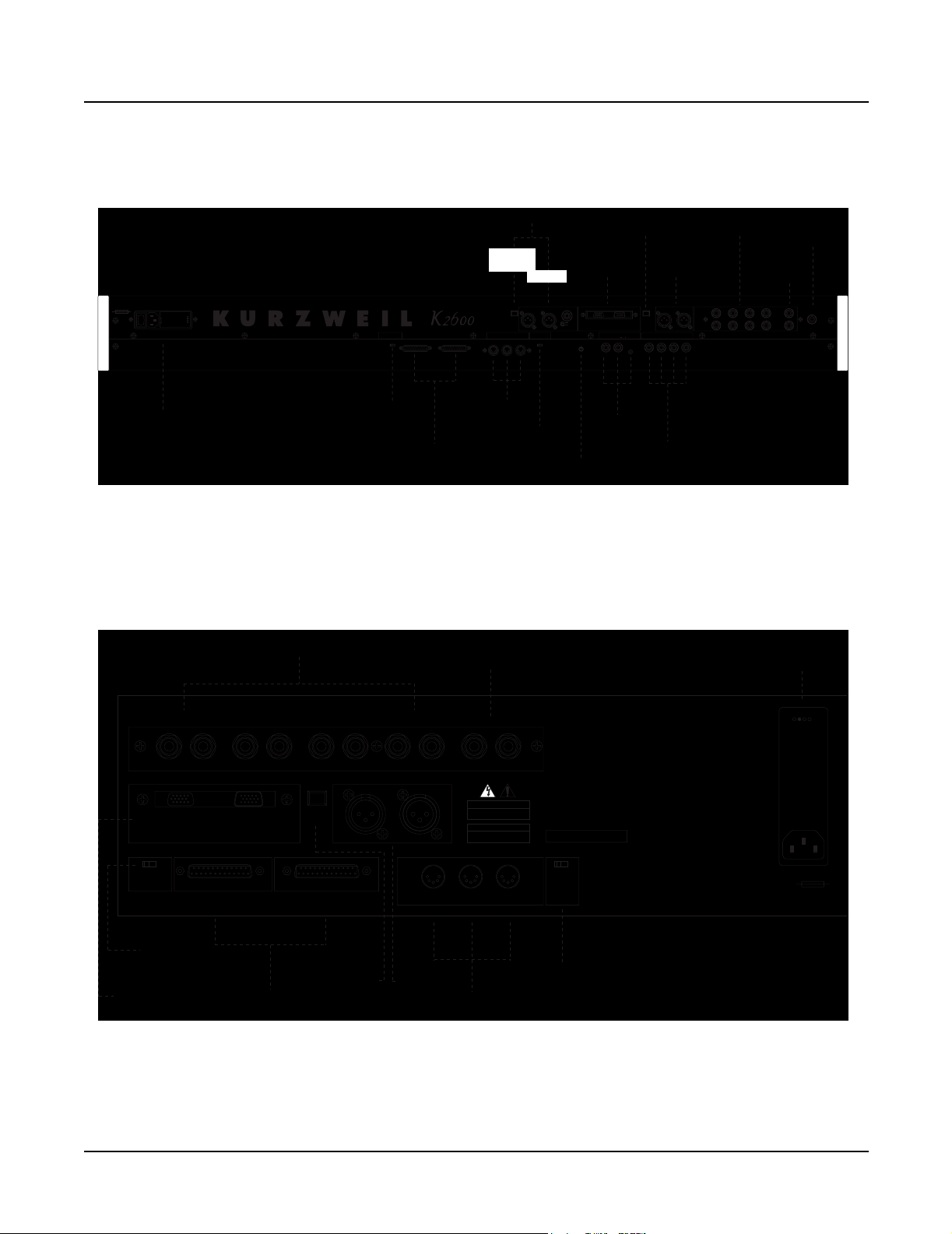
K2600R Rear Panel
Analog Outputs
Bal/Unbal
SCSI Termination
Auto / Disable
SCSI
Termination
Switch
SCSI
SCSI
Ports
SCSI Thru
Optical
MIDI
In Thru / Out Out
MIDI
Ports
Mix
Outputs
Inputs
In
Analog
Analog Inputs
Optical
In
Lo ZLeft RightLo Z
MIDI Select
Thru / Out
MIDI
Select Switch
Kurzweil
Kurzweil I/O
Left
Right
Hi Z
LCD Contrast
LCD
Contrast
Optical
I/O
KDS Out DMTi In
CC Pedals / Breath
Breath12or
CC Pedals/
Breath
Out
Digital
Digital I/O
Optical
Out
Out In
Switch Pedals
1234
Switch
Pedals
Analog Outputs
I/O
Analog Outputs
Bal/Unbal
Bal/Unbal
Left
BDCA
Right
Headphones
Mix
Outputs
(mono)
Mix
Headphones
Power
Entry Module
1-2
Bal/UnbalAnalog Outputs
A
LR
Kurzweil I/O
KDS Out DMTi In
Auto/Disable
THIS DEVICE COMPLIES WITH PART 15 OF THE FCC RULES. OPERATION IS SUBJECT TO THE FOLLOWING TWO CONDITIONS:
(1) THIS DEVICE MAY CAUSE HARMFUL INTERFERENCE, AND (2) THIS DEVICE MUST ACCEPT ANY INTERFERENCE
RECEIVED, INCLUDING INTERFERENCE THAT MAY CAUSE UNDESIRED OPERATION.
SCSI
B
LR
Optical
Out
SCSI Thru
SCSI
Termination
Switch
Kurzweil
I/O
SCSI
Ports
Figure 1-2 K2600R rear panel
C
LR
Digital I/O
Out In
Optical
Out
D
LR
MIDI
In Thru / Out Out
Digital
I/O
Mix
(mono)
LR
CAUTION
RISK OF ELECTRIC SHOCK
DO NOT OPEN
ATTENTION
RISQUE DE CHOC ELECTRIQUE
NE PAS OUVRIR
MIDI
Ports
WARNING:
WHEN TRANSPORTING
RACK-MOUNTED K2600R,
SUPPORT REAR OF UNIT
TO PREVENT DAMAGE.
WARN ING:
TO REDUCE RISK OF FIRE AND
ELECTRIC SHOCK, DO NOT
EXPOSE THIS PRODUCT TO
RAIN OR MOISTURE.
Mfr: Young Chang Akki, Co., LTD
Made in Korea
Serial No.
MIDI SelectSCSI Termination
Thru / Out
MIDI
Select Switch
WARNING:
FOR CONTINUED PROTECTION AGAINST THE RISK
OF FIRE, REPLACE ONLY WITH THE SAME TYPE AND RATING OF FUSE.
ATT ENTION:
UTILISER UN FUSIBLE DE RECHANGE DE MEME TYPE.
100/120/230/240V ~ AC
1.5/.75 A
48-65 Hz
100/120V ~ F2.0A 250V slow-blow
230/240V ~ F1.0A 250V slow-blow
Page 15

Rear Panel Features
All Models
• Mix Outputs, use these two 1/4” jacks (Left is mono) to connect either T/S or T/R/S cables.
• Analog Outputs Bal/Unbal, configure these 1/4” jacks (four pairs, A–D) as stereo pairs of
individual mono outputs.
• SCSI ports, use these two ports to connect a hard drive or other SCSI devices.
• SCSI Termination switch, a slide switch to select either Auto or Disable for SCSI termination.
• MIDI ports, In, Thru/Out, and Out, to use with other MIDI devices to receive, pass, and
send MIDI data.
MIDI Select switch, a slide switch to select the operation of the Thru/Out port.
•
• Kurzweil I/O, use these serial ports to send or receive the Kurzweil KDS format.
• Digital I/O, use these XLR jacks to send or receive digital information.
• Optical Out, use this jack to send or receive digital information from external devices with
an optical in jack.
Introduction
Rear Panel Features
Keyboard Models only
• Power Entry Module, includes the power switch, AC connector, fuse holder, and voltage
select switch.
• LCD Contrast, turn this potentiometer to adjust the LCD for the best visibility.
• CC Pedals/Breath, use these two 1/4” jacks to connect external control pedals (10kΩ linear
taper potentiometer, ring/tip/sleeve). Use the 3.5mm jack to connect a breath controller.
• Switch Pedals, use these four 1/4” jacks to connect footswitches.
• Inputs, this section is covered by a plate if the sampling option is not installed.
• For units with the sampling option, use either the two Lo Z XLR or the Hi Z 1/4”
(tip/ring/sleeve) jacks for sampling from an analog source.
• Optical In, If sampling from a digital source with an optical out jack, use this input.
• Headphones: use this 1/4” jack to connect headphones.
Rack Models only
• Power Entry Module, includes the AC connector, fuse holder, and voltage select switch.
1-3
Page 16
Introduction
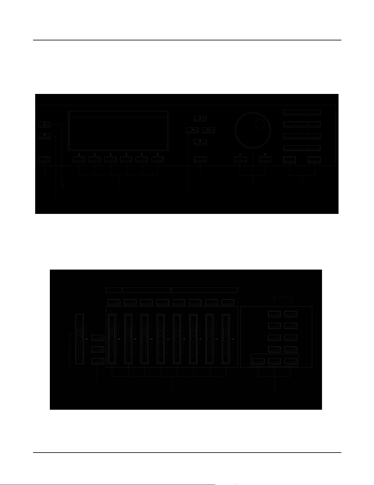
K2600/X Front Panel
K2600/X Front Panel
Data Entry
Chan/Bank
Layer/Zone
Edit
123
ABC DEF GHI
456
JKL MNO PQR
789
STU VWX YZ
+ / - 0 Clear
Exit
Cancel Enter
Space0-9UPPER/lower
Exit
button
Layer/Zone
button
Chan/Bank
button
LCD,
soft buttons
Figure 1-3 Data Entry Section
Assignable Controllers
Master Volume
Solo
Mixdown
MIDI Faders
Rotary Vibrato Percussion
Fast / Slow On / Off
12345678
ABCDEF GH
Chorus /
Vibrato
KB3 Controllers
Depth
1 / 2 / 3
On / Off
Cursor
buttons
Volume
Loud / Soft
Exit
button
Decay
Fast / Slow
Pitch
High / Low
Alpha Wheel,
Minus, Plus
buttons
Mode
Mute 1
Zoom - Gain -
Mute 2
Zoom +
Mute 3
Samp/Sec
Record Play/Pause Stop
Mode
buttons
Program MIDI
Setup Master
Q Access
Song
Effects Disk
Alphanumeric
buttons
Previous Pg
Mark
Gain +
Jump
Link
CompareFX Bypass
1-4
Master
Volume
slider
Solo,
Mixdown,
MIDI Faders
buttons
Assignable
and KB3 controllers
Figure 1-4 Assignable Controllers and Mode Sections
Record,
Play/Pause,
Stop buttons
Page 17

Front Panel Features
All Models
• LCD, backlit graphic display
• Soft buttons, use these buttons to select an action or item shown directly above a button in
the LCD.
• Cursor buttons, use these buttons to navigate through the LCD.
• Alpha Wheel, use the Alpha Wheel to increase or decrease a value by one or several increments.
• Plus (+) and Minus (–) buttons, these buttons operate similar to the Alpha Wheel. Pressing
the Plus (+) or Minus (-) button allows you to increase or decrease a value by one.
Alphanumeric Keypad, use these buttons to enter characters (both uppercase and
•
lowercase), numbers, and spaces.
• Mode buttons, use these buttons to select one of the eight operating modes.
• Chan/Bank and Layer/Zone buttons, depending on the current editor, use these buttons to
scroll through layers, presets, values, and zones.
• Exit button, press this button to leave the current editor.
• Edit button, use this button to modify a selected object or parameter.
Introduction
Front Panel Features
Keyboard Models only
• Master Volume slider, adjusts the overall volume of the mixed audio outputs and the
headphone jack.
• Assignable and KB3 Controllers, use these buttons to define the functions of these sliders
for zones or KB3 organ programs.
• Record, Play/Pause, and Stop buttons, use these buttons in Song mode.
• Solo button, this button mutes all but the current zone.
• Mixdown button, press this button to enter the Mixdown page to select the functions of the
physical controllers during MIDI mixdown.
• MIDI Faders button, press this button to enter the MIDI Faders page to define the functions
of the sliders.
• Ribbon Controller (not shown), define the parameters for the ribbon controller to respond
to finger positions and pressure. It can be programmed to control one section or up to three
sections.
• Disk Drive (not shown), use the disk drive to load, save, and copy data to a floppy disk.
• Mod/Pitch Wheel Assembly (not shown)
• Mod and Pitch wheels, use these wheels to vary modulation and pitch.
• Small Ribbon Controller, use this controller to add expression such as vibrato.
• SW1 and SW2 buttons, assignable buttons for use in the Setup Editor.
1-5
Page 18
Introduction
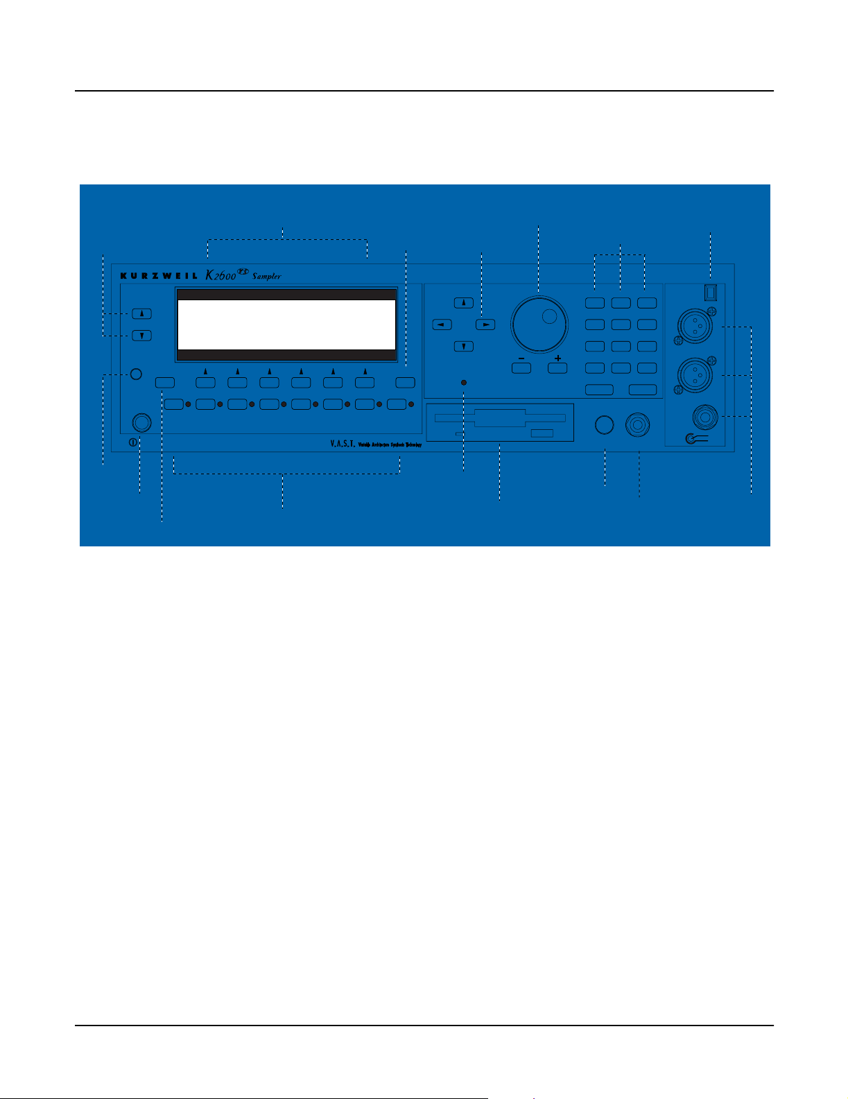
K2600R Front Panel
K2600R Front Panel
Chan/Bank,
Layer/Zone
buttons
LCD
Contrast
Chan/Bank
Layer/Zone
Edit
LCD
Contrast
Program MIDISetup Master SongEffects DiskQ Access
Mute 1 JumpMute 2 Mute 3 CompareFX Bypass MarkPrevious Pg
Power
Power
Edit
button
Figure 1-5 Front panel, K2600RS rack model
LCD and
Soft buttons
(below)
MIDI LEDMIDI LED
Mode
buttons
Alpha wheel,
Minus (–) and
Plus (+) buttons
Exit
button
Exit
LinkSamp/SecZoom +Zoom - Gain - Gain +
Cursor
buttons
MIDI
Alphanumeric
buttons
123
ABC DEF GHI
456
JKL MNO PQR
789
STU VWX YZ
+ / - 0 Clear
Cancel Enter
Volume
Space0-9UPPER/lower
Headphone
InputsData Entry
Optical
Lo Z
Hi Z
Optical
In
Left
Right
Left
Right
MIDI LED
Disk Drive
Volume
Headphone
Inputs
Rack Models only
• Power switch, push switch to turn the unit on and off.
• MIDI LED, this LED flashes when receiving data from a MIDI controller.
• Headphone jack, use this 1/4” jack to connect headphones.
• Volume potentiometer, adjusts the overall volume of the mixed audio outputs and the
headphone jack.
• LCD Contrast, turn this potentiometer to adjust the LCD for the best visibility.
• Disk Drive, use the disk drive to load, save, and copy data to a floppy disk. Use formatted
double-sided, double density (DSDD—720K or high-density (HD—1.4M) disks.
Inputs, this section is covered by a plate if the sampling option is not installed.
•
• For units with the sampling option, use either the two Lo Z XLR or the Hi Z 1/4”
(tip/ring/sleeve) jacks for sampling from an analog source.
• Optical In, If sampling from a digital source with an optical out jack, use this input.
1-6
Page 19
Chapter 2
Diagnostics
Diagnostic Tests
Test Name Description
LCD Tests the LCD
Engine Blk Tests the Operating System (installed in FlashROM)
Object Blk Tests the Setups (installed in FlashROM)
RAM/PRAM Tests the RAM (volatile, non-volatile and expansion)
I/O Port Tests the Microcontroller’s port pins
FDD Init Tests the Floppy Disk Drive controller
Scanner Tests the Scanner communications
MIDI Uart Tests MIDI In and Out
FDD R/W Tests the Floppy Disk Drive
SCSI Tests drive(s) on the SCSI bus
VLSI & ZRAM Tests Janis, Hobbes, and Lisa (not Lisa option)
Sampling Opt Tests the Sampling Option
Sine Wave Tests the sound hardware with sine waves
Sound ROM Tests the Sound ROM
Sound RAM Tests the Sound RAM
1st NVRAM Writes to the Non-Volatile and Expansion RAM
2nd NVRAM Checks the pattern written by the 1st NVRAM test
Digital IO Tests the Lisa Option
Table 2-1 Diagnostic Tests
Saving User Data
Warning: Be sure to save all user data and remove any user disk from the disk drive before
entering diagnostics.
To save user data, insert a formatted floppy disk into the disk drive and press the Disk button.
In Disk Mode, use the
in the LCD. Press the soft button under OK and follow the instructions displayed in the LCD.
See Saving User Data on page 5-2 for additional information.
Down cursor button to scroll through the list until Everything appears
Page 20
Diagnostics
Entering Diagnostics
Entering Diagnostics
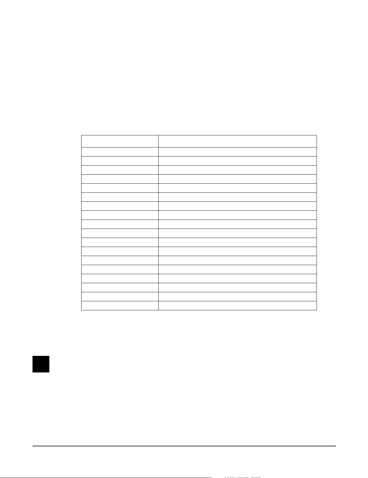
1. Apply power to the unit. When the Please wait... message appears in the LCD,
quickly press and release the Exit button. The LCD shows the following:
------ K2600 Boot Loader v1.00 ------
Install System Hard Reset
Install Objects Run Diags
Run System Fixed Diags
OK
Figure 2-1 LCD example, boot loader menu
2. Use the cursor buttons or turn the Alpha Wheel until Run Diags is highlighted. Press the
soft button under OK.
3. The LCD briefly shows a message that the integrity of the operating system is being
checked and then displays a message warning you that some diagnostic tests will erase
data stored in user RAM.
Warning: If you have not saved the data stored in user RAM and wish to do so before
proceeding, turn the unit off to exit the diagnostic tests, power up and save the data. If
you need instructions, refer to Saving User Data on page 5-2.
4. If you have already saved data stored in user RAM, press any button to continue.
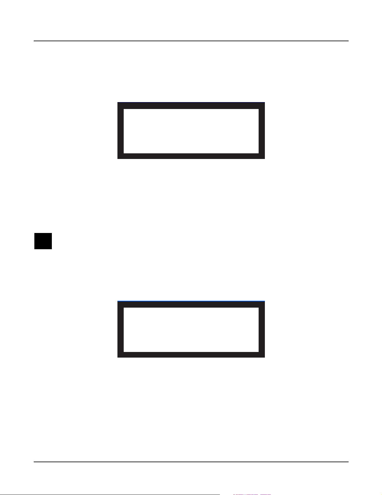
5. The LCD shows the following:
------ K2600 Diagnostic Ver 1.03 -----LCD Scanner Sine Wave
Engine Blk MIDI Uart Sound ROM
Object Blk FDD R/W Sound RAM
RAM/PRAM SCSI 1st NVRAM
I/O Port VLSI & ZRAM 2nd NVRAM
FDD Init SamplingOpt Digital IO
BurnIn Forever OK
Figure 2-2 LCD example, K2600 diagnostic menu
LCD and Front Panel Buttons
The LCD displays the list of tests, test modes, actions, and test results.
Press the Left, Right, Up, or Down cursor buttons or turn the Alpha Wheel to navigate through
the available tests.
2-2
Use the soft buttons located below the LCD to select different test modes or actions.
Page 21
Test Results
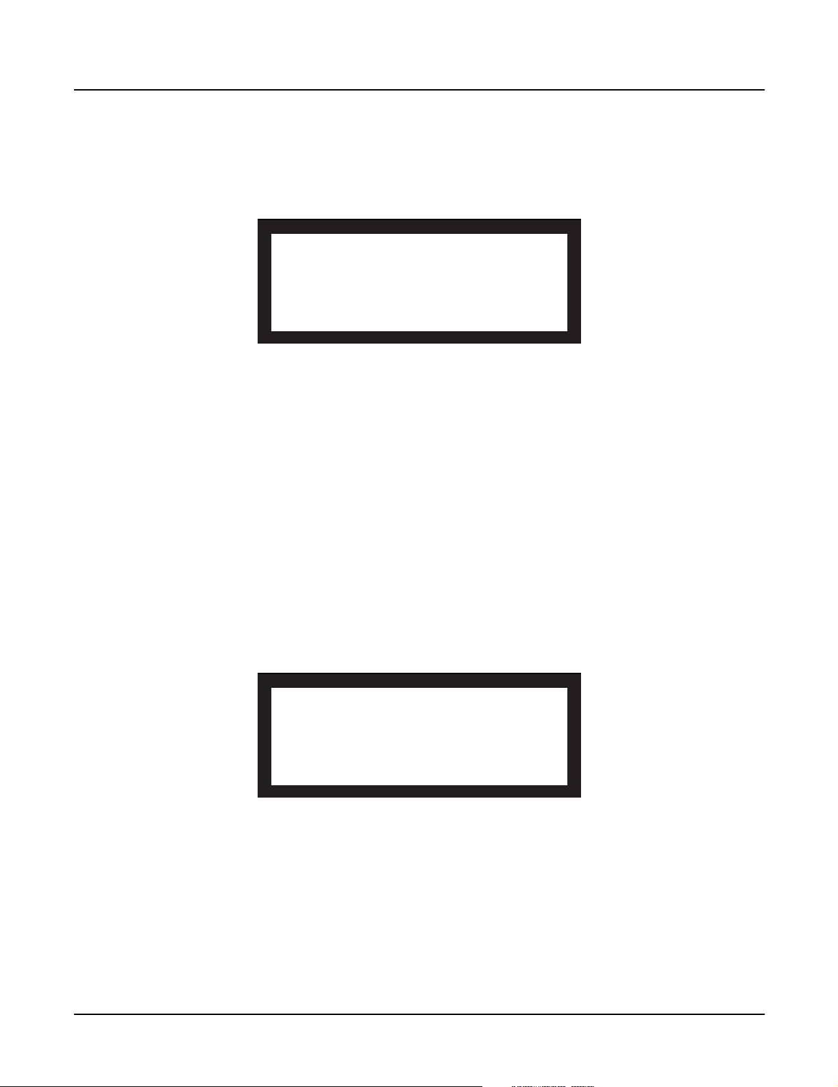
At the completion of an individual test, the LCD displays the results of the test. Figure 2-3 shows
an example of the display for the Engine Blk test.
Test Item : Engine Blk
Please wait. Testing...Success
Press any key to continue...
Figure 2-3 LCD example, Engine Blk test
Diagnostic Test Menus
After following the steps described in Entering Diagnostics, you’ll see the main diagnostic menu
in the LCD. The following describes the steps required to run the tests in the three menus.
Diagnostics
Diagnostic Test Menus
Main Menu
To run an individual test, press Left, Right, Up, or Down cursor buttons or turn the Alpha
Wheel to highlight the test name, then press the soft button below OK to execute the test. When
the test has completed, whether pass or fail, press any button to return to the main menu and
use the cursor buttons or Alpha Wheels to select another test.
Burn-In Menu
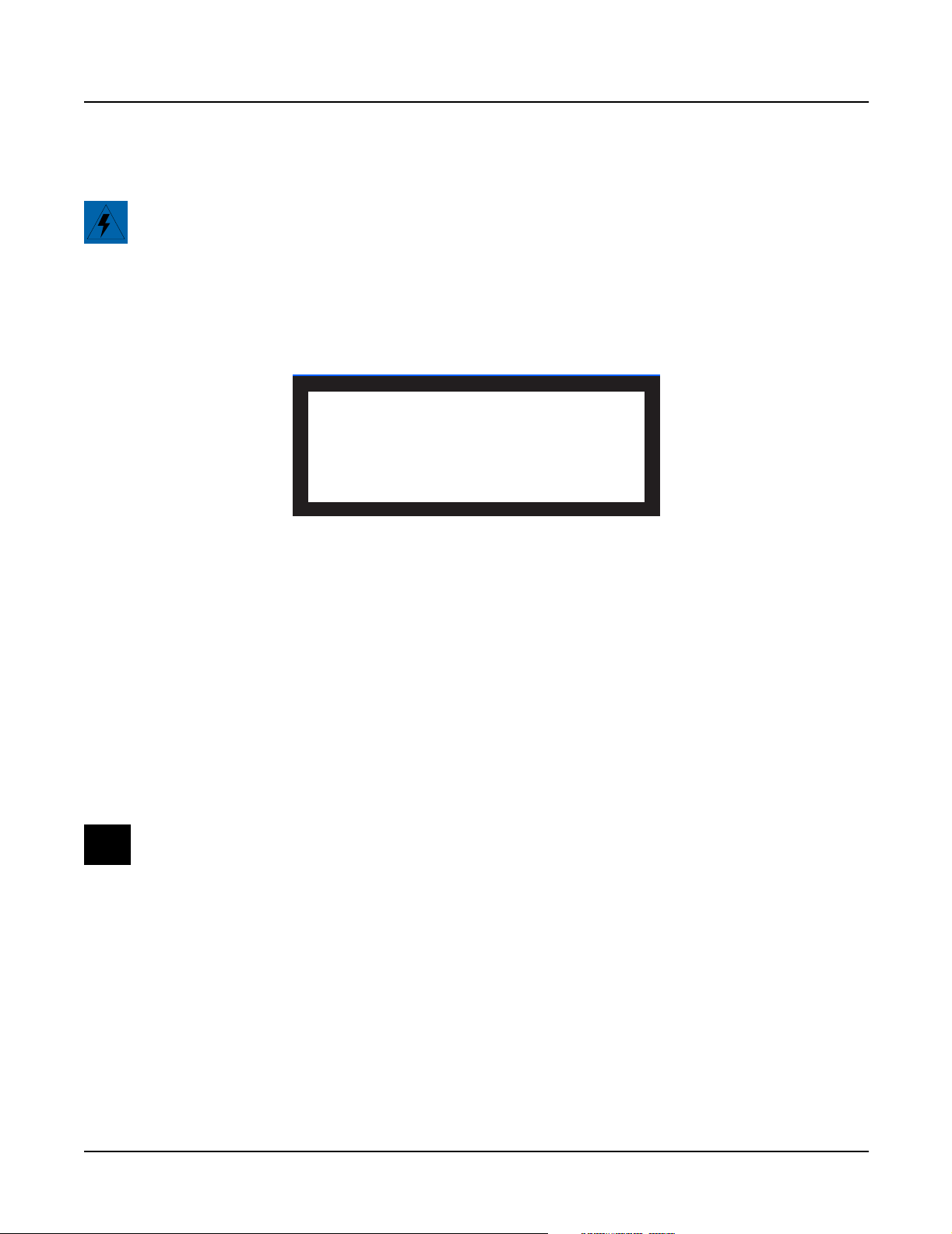
Burn-In continuously runs the sequence of tests listed in Figure 2-4.
Figure 2-4 LCD example, Burn-In tests
Press the soft button below Burn-In in the LCD to begin running the tests. The tests continue to
run until you press the Exit button.
LCD : PASS Scanner : PASS
Engine Blk : PASS FDD R/W : PASS
Setup Blk : PASS Sound ROM : PASS
RAM/PRAM : PASS Sound RAM : PASS
I/O port : PASS
FDD Init : PASS
EXIT-Stop Diags. Total-0000 Fail-0000
Forever
Forever continuously runs an individual test. The test continues to run until you press the Exit
button. The number of tests performed and the result is displayed in the LCD. You can return to
the diagnostic main menu by pressing the soft button below EXIT-Stop Diag. in the LCD.
2-3
Page 22

Diagnostics
Description of Tests
Description of Tests
LCD
This test writes a group of characters to the LCD and verifies that the same characters can be
read back again. The LCD Test includes four test phases that run automatically. The four steps
include the following:
1. Data test phase for the LCD character display memory
2. Address test phase for the LCD character display memory
3. Data test phase for the LCD graphics display memory
4. Address test phase for the LCD graphics display memory
The data test phase repeatedly writes the following 17-byte data pattern to the LCD:
0x00, 0xFF, 0x00, 0x0F, 0xF0, 0xCC, 0x33, 0xAA, 0x55, 0x11, 0xEE, 0x22, 0xDD, 0x44, 0xB, 0x88, 0x77
After the pattern is written, it is read back. If a difference is detected, the test fails.
The address test phase writes consecutive values to consecutive locations in the LCD. Then
these values are read back. If a difference is detected, the test fails.
A failure of this test indicates a problem with the LCD, Engine Board, connections between the
two boards or related circuitry.
Engine Blk (Engine Block)
This test computes an observed 32-bit check value of the setup area of the Flash ROMs (U4 and
U5) on the Engine Board. This value is then compared to the expected value, which is stored in
the flash itself. If the values differ, an error is reported.
If this test fails, install the latest Operating System and run the test again.
A failure of this test indicates a problem with the microcontroller, Flash ROMs, or related
circuitry on the Engine Board.
Object Blk (Object Block)
This test computes an observed 32-bit check value of the setup area of the Flash ROMs (U4 and
U5) on the Engine Board. The value is then compared to the expected value, stored in the Flash
ROMs. If the values differ, the test fails.
If this test fails, install the latest Operating System and Objects and run the test again.
A failure of this test indicates a problem with the Flash ROMs or related circuitry on the Engine
Board.
2-4
Page 23
RAM/PRAM
Caution: This test destroys all non-volatile user RAM! If you haven’t already saved user data,
power cycle the unit and save the data now. If you need instructions, refer to Saving User Data on
page 5-2.
The RAM/PRAM test performs a data test and an address test on each of the processor RAM
sections. These sections include volatile RAM at addresses 0x2100000 through 0x213FFFF and
the non-volatile RAM at addresses 0x02000000 through 0x0203FFFF.
Figure 2-5 LCD example, RAM/PRAM test
Diagnostics
Description of Tests
Test Item : RAM/PRAM
PRAM Present
Please wait. Testing...Success
Press any key to continue...
I/O Port
If the PRAM optional expansion non-volatile RAM is installed, this test checks addresses
0x01F00000 through 0x01FFFFFF. After the volatile and non-volatile RAM is tested, the message
PRAM Present is displayed in the LCD. If the PRAM optional expansion is not installed, the
LCD shows PRAM Absent.
The data test phase of this test writes a value derived from a 23-word test sequence to each RAM
location. While the value is in memory, it is bitwise-inverted twice. This should bring the data
back to its original value. The data is then compared with the original data. If a difference is
detected, an error occurs and the test fails.
The address-test phase of this test writes RAM addresses sequentially throughout RAM. The
addresses are then read back. If a difference is detected, an error occurs and the test fails.
A failure of this test may indicate a problem with the RAM or related circuitry.
Note: If a PRAM option is installed and the test fails, remove the optional PRAM Board and
rerun the test.
If the PRAM optional expansion RAM is installed and the LCD shows PRAM Absent, be sure
that the PRAM option board is correctly installed. If the LCD doesn’t show PRAM Present,
there may be a problem with either the PRAM Board, the Engine Board or related circuitry.
The I/O Port test mutes and unmutes the audio circuitry to verify that the signal is transmitted
correctly.
A failure of this test may indicate a problem with the Engine or DSP Board.
2-5
Page 24

Diagnostics
Description of Tests
FDD Init (Floppy Disk Drive Initialize)
Note: Insert a blank formatted disk into the floppy disk drive before running this test!
The FDD Init test recalibrates the disk drive.
A failure of this test may indicate a problem with the connection between the floppy drive and
the Engine Board, the floppy drive, or floppy drive’s controller (U9 on the Engine Board).
Scanner
This test lights sequentially the LEDs for the eight mode select buttons:
Program, Setup, Q Access, Effects, MIDI, Master, Song, and Disk
This test confirms scanner communications by sending data to the scanner, 37451, (U1 on the
Scanner Board-keyboard units and on the Front Panel/Scan Board-rack units). After processing
the data, the scanner sends a result back to the main processor (U3 on the Engine Board). If the
returned value is not as expected or if the scanner does not reply as expected, the test fails.
Failure of this test indicates a failure of the main processor or the scanner. Note that failed
scanner communications will likely disable operating the diagnostics from the control panel,
since control panel signals must be read and written through the scanner.
MIDI Uart
The MIDI Uart test performs a loop-back of the serial port by sending a 23-byte pattern over the
external MIDI link. This test requires a MIDI loop (a MIDI cable that connects two MIDI jacks).
The test will fail if a MIDI cable is not connected between two MIDI jacks. Be sure to run this test
with MIDI cables connected as follows:
Note: Be sure to use a functional MIDI cable!
1. Connect a MIDI cable to the MIDI In and MIDI Out jacks and run the test.
2. Connect a MIDI cable to the MIDI In and MIDI Out/Thru jack and set the Out/Thru
switch on the rear panel to Out. Run the test.
Failure of this test could be caused by failure of the serial port, other MIDI circuitry, or a problem
on the Engine or DSP Board.
FDD R/W (Floppy Disk Drive Read/Write)
Note: Insert a blank formatted disk into the floppy disk drive before running this test! Be sure to
insert a blank disk; any data on the disk will be lost and could cause this test to fail.
This test initializes the floppy disk drive and performs a write/read test of the disk in the drive.
2-6
If this test fails, check the cable connections from the floppy disk drive to the Engine Board.
Failure of this test may indicate a problem with the floppy disk drive, the floppy drive’s
controller (U9 on the Engine Board), or related circuitry.
Page 25
SCSI
Diagnostics
Description of Tests
The LCD shows the following when you select the SCSI test.
ID# scsiType Rest ID# scsiType Rest
0 Not Found !! 4 Not Found !!
1 Not Found !! 5 Not Found !!
2 Not Found !! 6 Not Found !!
3 Not Found !!
Press any key to continue...
Figure 2-6 LCD example, SCSI test
The SCSI tests the functionality of the SCSI ports. This test sets the K2600’s SCSI ID to 7 and
scans the SCSI bus. When it finds a connected SCSI device (such as an internal or external hard
drive) the K2600 writes random data to each block, then checks to see if data has been retained.
Warning: The attempt is made to retain user data on an internal or external hard drive by
saving the contents of each block before testing and restoring it at the completion of the test.
However, it is always wise to back up critical data prior to executing this test.
Failure of this test may indicate a problem with SCSI ID settings, a fault of the SCSI device or
connection, or a problem on the Engine Board.
Note: For more information on SCSI configurations and guidelines, refer to the K2600 Series
Musician’s Reference and Musician’s Guide.
VLSI & ZRAM
The test writes data to the VLSI chip registers and internal RAM, and then confirms that the data
has been retained by these memories. The following lists the areas that are tested. This list does
not, however, correlate to the testing sequence.
Hobbes
• Hobbes time slot data
• Hobbes accumulator store
• Hobbes dither store
• Hobbes output unit-hold register
Janis
• Janis channel registers
• Janis sample cache
2-7
Page 26
Diagnostics
Description of Tests
Lisa
• Lisa microcode RAM (only Engine Board Lisa), not optional
Failure of this test generally indicates a problem on the DSP Board; it should be replaced.
Sampling Opt (Sampling Option)
Figure 2-7 illustrates the full menu of sampling option tests. To display this page, select
Sampling Option from the main menu and use the Up or Down button or the Alpha Wheel to
scroll through the menu options.
Test complete sampling option
Test access to sampling option
Test analog-sampling circuitry
Test digital-sampling circuitry
Return to main menu
OK
Figure 2-7 LCD example, Sampling Option test
Note: If the sampling option is not installed, the LCD indicates that the option is not installed.
You can select the first option to test the complete sampling option, or choose from one of the
following:
Test access to sampling option
This test plays a 1KHz sine wave in left output C, plays a 1.5KHz sine wave in right output C,
and performs a series of one-second samples from the internal audio loopback from the Audio
Board. These samples are acquired using each of the four access modes, and a number of
measurements are made on each sample.
Test analog-sampling circuitry
The LCD prompts you to perform the following:
Insert a pair of patch cables (1/4"
stereo male to XLR male) between audio
output pair B and the balanced inputs of
the sampling option.
OK
LK
2-8
Figure 2-8 LCD example, analog-sampling
This test plays a 1KHz sine wave in the left channel and a 1.5KHz sine wave in the right channel.
Page 27
Description of Tests
Test digital-sampling circuitry
The LCD prompts you to perform the following:
Remove any patch cables from the
balanced inputs of the sampling option.
Insert a digital-audio cable (XLR male
to XLR female) between the Digital In
and Digital Out jacks.
OK
LK
Figure 2-9 LCD example, digital-sampling
This test plays a 1KHz sine wave in the left channel and a 1.5KHz sine wave in the right channel.
These sine waves are not sampled, but are merely used to generate digital data with which to
test the digital audio circuitry.
Note: For more information on sampling, refer to the K2600 Series Musician’s Reference and
Musician’s Guide.
Diagnostics
Sine Wave
This test produces six sine waves to confirm the clarity of each sine wave.
Warning: This test generates loud constant sine waves! Before executing this test, turn the
volume on the K2600 and your sound system down to minimum.
As soon as this test is executed, you should hear the first sine wave. Press any button or move
the Alpha Wheel to step through the remaining five frequencies.
Note: The LCD does not prompt you during this test. You must press a button or move the
Alpha Wheel to administer this test!
To test the frequency of each sine wave, connect an oscilloscope to the headphone or mix output
jacks. The six sine waves should generate at the following frequencies:
To hear each sine wave, connect a set of headphones to the headphone jack and begin running
the test.
A failure of this test may indicate a problem with the Engine Board, Audio Board, or related
circuitry.
100Hz, 500Hz, 1KHz, 2.5KHz, 5.0KHz, 10.0KHz
2-9
Page 28
Diagnostics
Description of Tests
Sound ROM
The Sound ROM test performs a checksum of each megabyte of Sound ROM. The computed
checksum is compared to the checksum stored in ROM.
The asterisk groups displayed in the LCD change to PASS or FAIL at the completion of each
sound block test. If a sound block is not installed that portion will fail.
Sound ROM Test
Base Pian Orch Cont ROM3 ROM4
Meg 0 **** **** **** **** **** ****
Meg 1 **** **** **** **** **** ****
Meg 2 **** **** **** **** ****
Meg 3 **** **** **** **** ****
Press any key to continue...
Figure 2-10 LCD example, Sound ROM test
A failure of this test indicates a problem with a Sound ROM or the Engine Board.
Sound RAM
Note: The length of the testing time to run this test depends on the amount of RAM installed.
The more RAM present, the longer the test time. The test time for each megabyte of RAM is
approximately 20 seconds. It should take approximately 15 minutes to run this test for a unit
with 128M.
This test checks the amount of sound RAM installed and displays the amount found in each
bank in the LCD. The test then writes a bit pattern to each block of sound RAM. The bit pattern
is confirmed and an inverse of this pattern is written into RAM for confirmation.
Figure 2-11 LCD example, Sound RAM test
A failure of this test may indicate a problem with the SIMMs, their installation, the Engine
Board, or related circuitry.
Test Item : Sound RAM
Bank 0: 32M Bank 2: 32M
Bank 1: 32M Bank 3: 32M
Please wait. Testing...
Press any key to continue...
2-10
Page 29
1st NVRAM
Caution: This test destroys all non-volatile user RAM! If you haven’t already saved user data,
power cycle the unit and save the data now. If you need instructions, refer to Saving User Data on
page 5-2.
The 1st NVRAM test checks the function of the battery-backed RAM by writing a bit pattern to
it, and works in conjunction with the 2nd NVRAM test. After the test is executed, the LCD
prompts you to remove power from the unit, wait two minutes, apply power, and immediately
execute the 2nd NVRAM test.
Diagnostics
Description of Tests
Test Item : 1st NVRAM
PRAM Present
Please wait. Testing...Complete !!!
Please power off and on again !!!
AND select '2nd NVRAM' in first menu.
Figure 2-12 LCD example, 1st NVRAM test
2nd NVRAM
This test confirms that the bit pattern written to it during the 1st NVRAM test has been retained,
thereby constituting a successful test.
A failure of this test may indicate a problem with the battery, or related circuitry on the Engine
Board.
Digital IO
This test performs a test of the microcode RAM and delay RAM of all Lisa chips on the Digital
IO option. If this option is not installed, the LCD indicates not found.
2-11
Page 30

Diagnostics
Description of Tests
2-12
Page 31

Chapter 3
K2600R Disassembly/Assembly
Introduction
The chapter contains all the procedures for the disassembly and assembly of the K2600R
instruments including factory-installed and after-market options. In some instances a procedure
may instruct you to remove a cable from an after-market option board or device that may not be
present. Simply skip this step of the procedure and continue.
Saving User Data
Warning: Be sure to save all user data and remove any user disk from the disk drive before
disassembly.
To save user data, insert a formatted floppy disk into the disk drive and press the Disk button.
In Disk Mode, use the Down cursor button to scroll through the list until Everything appears
in the LCD. Press the soft button under OK and follow the instructions displayed in the LCD. For
detailed instructions to save the user data, please refer to Saving User Data on page 5-2.
Cables, Connectors
All flat ribbon cable connectors are keyed, and therefore cannot be reversed. Flat ribbon cables
have locking cable clips. Be sure to reapply the clips when connecting cables.
In some cases, tape secures cable connections or fastens cables to the top cover and bottom
enclosure. Always peel back the tape from one side when disconnecting cables so that the tape
remains properly positioned.
Tools Required
• No. 1 Phillips head screwdriver
• No. 2 Phillips head screwdriver
• No. 2 Phillips head screwdriver right angle
• 1/2” nut driver
• 5MM nut driver (hex standoffs)
• Allen Wrench
• Foam blocks
Page 32

K2600R Disassembly/Assembly
Opening the K2600R
Opening the K2600R
Removing the Top Cover
Before you begin disassembly, please be sure that the power is off, and that the AC cord and all
other cables are disconnected.
1. The top cover is secured to the K2600R with ten screws: four screws on each side of the
unit and two screws on the rear.
2. Remove the four screws on the left and four screws on the right side of the top cover.
Notice that the screws positioned closest to the rear panel are shorter.
3. Remove the two screws (use #1 screwdriver) from the upper rear panel edge of the top cover.
4. The top cover locks into a groove on the Front Panel Assembly. To remove it, lift it and
slide it back toward the rear panel.
5. Place the top cover safely aside to avoid damage.
Remove
screws
Remove
screws
Remove
screws
(shorter)
Figure 3-1 K2600R Removing the top cover
Replacing the Top Cover
1. Place the top cover in position and move it toward the Front Panel Assembly to slide it
into the groove on the Front Panel Assembly.
2. Install the four screws on the left and right sides of the top cover.
Slide top cover toward rear panel
Remove
screws
(shorter)
Remove
screws
(use #1 screwdriver)
3-2
Caution: Be sure to install the shorter screws closest to the rear panel. Failure to do so
could damage or short out components located near these positions.
3. Install the two screws on the rear panel edge of the top cover.
Page 33

Removing the Audio Board
1. Disconnect the cables listed in Table 3-1.
All flat ribbon cables use cable locking clips that secure the cables to the connectors.
Remove the cable locking clip from the flat ribbon cable on the Audio Board. Be sure to set
it safely aside so that you can reinstall it when you reconnect the cable.
Ref. Name Cable Type Destination
J601 DAC flat ribbon CPU Board
J602 Audio Power stranded Power Supply Board
J611 Sampler shielded wire Sampling Board
J612 Volume shielded wire Phone/Volume Board
J615 Phones shielded wire Phone/Volume Board
Table 3-1 K2600R Audio Board cables
2. Remove the three screws that secure the Audio Board to the rear panel.
K2600R Disassembly/Assembly
Opening the K2600R
3. Remove the Audio Board.
Replacing the Audio Board
1. Place the Audio Board in position so that the output jacks are aligned properly with the
openings provided for them in the rear panel.
2. Install the three screws that secure the Audio Board to the rear panel.
3. Connect the flat ribbon cable to location J601 and install the locking cable clip.
4. Connect the remaining cables listed in Table 3-1.
Removing the Digital I/O Option Board
You must remove the Audio Board before removing the Digital I/O Option Board. Follow the
procedure on page 3-3 to remove the Audio Board.
1. Remove the cap from the Optical Out jack.
2. Remove the two Digital I/O port screws.
3. Remove the four Digital I/O Out and In jack screws.
4. The Digital I/O Option Board is mounted component side down. Move the board slightly
toward the front panel to free the jacks from the openings provided for them in the rear
panel.
5. Disconnect the three cables listed in Table 3-2.
3-3
Page 34

K2600R Disassembly/Assembly
Opening the K2600R
Ref. Name Cable Type Destination
J1001 Digital I/O to DSP flat ribbon DSP Board
J1002 Sampling Bd. (SOB) shielded wire Sampling Board
J1003 Sampling Bd. (SOB) shielded wire Sampling Board
Table 3-2 K2600R Digital I/O Option Board cables
6. Remove the cable locking clip and disconnect the flat ribbon cable from the DSP Board.
7. Disconnect the shielded wire cables.
8. Remove the Digital I/O Option Board.
Replacing the Digital I/O Option Board
1. Hold the board vertically over the DSP Board (Digital I/O XLR jacks facing down) and
connect the shielded wire cables at locations J1002 and J1003 on the Digital I/O Option
Board.
2. Lower the board to a horizontal position and connect the flat ribbon cable. Be sure to
install the cable locking clip.
3. Position the board so the Digital I/O jacks, Optical jack, and Digital I/O ports are aligned
properly and through the openings provided for them in the rear panel.
4. Install the four screws that secure the Digital I/O Out and In jacks to the rear panel.
5. Install the two screws that secure the Digital I/O ports to the rear panel.
6. Install the cap on the Optical jack.
7. Follow the procedure on page 3-3 to replace the Audio Board.
Removing the Small Digital I/O Board
You must remove the Audio Board before removing the Small Digital I/O Board. Follow the
procedure on page 3-3 to remove the Audio Board.
1. Remove the cap from the Optical Out jack.
2. Remove the four screws that secure the Digital I/O Out and In jacks to the rear panel.
3. The Small Digital I/O Board is mounted component side down. Move the board slightly
toward the front panel to free the jacks from the openings provided for them in the rear
panel.
4. Disconnect the cables listed in Table 3-3.
3-4
Page 35

Ref. Name Cable Type Destination
J1201 Sampling Bd. (SOB) shielded wire Sampling Board
J1205 Sampling Bd. (SOB) shielded wire Sampling Board
Table 3-3 K2600R Small Digital I/O Board cables
5. Remove the Small Digital I/O Board.
Replacing the Small Digital I/O Board
1. Hold the board vertically over the DSP Board (Digital I/O XLR jacks facing down) and
connect the shielded wire cables at locations J1201 and J1205 on the Small Digital I/O
Board.
2. Lower the board and position it so that the Digital I/O jacks and Optical jack are aligned
properly with the openings provided for them in the rear panel.
3. Install the four screws that secure the Digital I/O Out and In jacks to the rear panel.
K2600R Disassembly/Assembly
Opening the K2600R
4. Install the cap on the Optical jack.
5. Follow the procedure on page 3-3 to replace the Audio Board.
Removing the DSP Board
You must remove the Audio Board before removing the DSP Board. Follow the procedure on
page 3-3 to remove the Audio Board. If the K2600R you are servicing has a Small Digital I/O or
Digital I/O Option Board installed, remove it before removing the DSP Board. Follow the
procedure on page 3-4 to remove the Small Digital I/O Board or page 3-3 to remove the Digital
I/O Option Board.
The DSP Board is mounted on the CPU Board and is held in place by four nylon PC board
standoffs and two 50-pin connectors.
1. Several cables are routed over the DSP Board. It is not necessary to disconnect all the
cables. However to make the removal of the DSP Board easier, we recommend
disconnecting two flat ribbon cables, as described in Steps 2 and 3.
2. On the CPU Board, remove the locking cable clip and disconnect the cable that connects
the LCD Board to the CPU Board.
3. On the Sampling Board, remove the locking cable clip and disconnect the cable that
connects the CPU Board to the Sampling Board.
4. After disconnecting the two flat ribbon cables, fold them back, away from the DSP Board.
5. There are two styles of nylon standoffs securing the DSP Board. The standoffs on the right
side of the DSP Board (as viewed standing at the rear panel) have tabs that clip over the
top edge of the DSP Board. The standoffs on the left side of the DSP Board protrude
through the DSP Board.
6. Start with the standoffs on the right of the DSP Board. Press the tabs of the standoffs away
from the DSP Board and slightly lift the right edge of the DSP Board to clear the tabs.
3-5
Page 36

K2600R Disassembly/Assembly
Opening the K2600R
7. To release the DSP Board from the standoffs on the left side of the board, squeeze the top
of the standoffs and slightly lift the left side of the DSP Board.
8. Once the DSP Board is free of the standoffs, lift the DSP Board straight up to disconnect
the two 50-pin connectors from the CPU Board.
Replacing the DSP Board
1. Place the DSP Board in position onto the four nylon PC board standoffs.
2. Verify that the DSP Board pins are lined up properly with the two 50-pin connectors
located on the CPU Board.
3. Press the DSP Board down to insert the pins on the back of the DSP Board into the two
50-pin connectors on the CPU Board. This will also secure the DSP Board into the four
standoffs.
4. Connect the flat ribbon cable from the CPU Board to the Sampling Board.
5. Connect the flat ribbon cable from the LCD Board to the CPU Board.
6. Be sure to replace the locking cable clips on the flat ribbon cables.
7. If the K2600R you are servicing has a Digital I/O Option, follow the procedure on
page 3-4 to replace it. If the K2600R you are servicing has a Small Digital I/O Board,
follow the procedure on page 3-5 to replace it.
8. Follow the procedure on page 3-3 to replace the Audio Board.
Removing the CPU Board
The CPU Board is secured at several locations. There are five attachment points on the bottom
enclosure. The first is a moveable holding bracket secured with a screw, see Figure 3-2. The other
four locations are mounting posts that rise up out of the bottom enclosure. Three nylon PC
board standoffs and a screw secure the CPU Board to the four mounting posts, see Figure 3-3.
The CPU Board is also held in place by the fasteners that secure the SCSI ports and MIDI jacks to
the rear panel.
Front panel
Holding
bracket
screw
Access panel
3-6
Rear panel
Figure 3-2 K2600R bottom
Page 37

K2600R Disassembly/Assembly
Opening the K2600R
1. Follow the procedures previously described to remove the Audio Board, Digital I/O
Option (if installed) or the Small Digital I/O Board, and the DSP Board.
2. Place the K2600R on its side. Hold the CPU holding bracket and remove the holding
bracket screw from the bottom enclosure. Place the CPU holding bracket aside.
screw
standoff
standoffs
Figure 3-3 K2600R internal attachment points
3. Place the K2600R flat in its normal position.
4. All flat ribbon cables use cable locking clips that secure the cables to the connectors.
Remove the cable locking clips from the flat ribbon cables on the CPU Board. Be sure to set
them safely aside so that you can reinstall them when you reconnect the cables.
5. Disconnect the cables listed in Table 3-4. All but one of these cables connect to the CPU
Board. The exception is Ref. J108, which connects to the Power Supply Board.
Note: The flat ribbon cable that connects the LCD Board to the CPU Board should already
be removed from location J804 on the CPU Board. Therefore, it is not listed in Table 3-4.
Ref. Name Cable Type Destination
J801 Sampler flat ribbon Sampling Board
J805 Floppy flat ribbon Disk Drive
J807 Floppy Power stranded wire Disk Drive
J808 DAC flat ribbon Audio Board
J813 Scanner flat ribbon Front Panel/Scanner Board
J814 DC Power stranded wire Power Supply Board
J108 Scanner Power stranded wire Front Panel/Scanner Board
Table 3-4 Cables to disconnect for CPU Board removal
3-7
Page 38

K2600R Disassembly/Assembly
Opening the K2600R
6. Remove the two screws that secure the MIDI jacks to the rear panel.
7. Remove the four hex standoffs and flat washers that secure the SCSI ports to the rear
panel.
8. Remove the screw that secures the CPU Board to the mounting post.
9. Press the tabs of the three nylon PC board standoffs away from the CPU Board and lift the
board clear of the tabs.
10. Remove the CPU Board by moving it toward the front panel to clear the SCSI ports and MIDI jacks.
Replacing the CPU Board
1. Place the CPU Board in position over the three nylon PC board standoffs. Be sure the SCSI
ports and MIDI jacks are positioned through the openings provided for them in the rear
panel.
2. Press the CPU Board down that secure it onto the standoffs.
3. Install the screw that secures the CPU Board to the mounting post.
4. Install the two screws that secure the MIDI jacks to the rear panel.
5. Install the four hex standoffs and flat washers that secure the SCSI ports to the rear panel.
6. Place the K2600R on its side.
7. Hold the CPU holding bracket in position over its mounting hole on the bottom enclosure
and install the screw through the bottom enclosure.
8. Place the K2600R flat in its normal position.
9. A number of CPU Board cables cross over the DSP Board. When reconnecting cables, do
so in the following order.
Connect the flat ribbon cable from the Front Panel/Scanner Board to the CPU Board,
location J813. Be sure to install the cable locking clip.
Caution: The Disk Drive and Sampling Option flat ribbon cables are the same size and
could easily be reversed. Be sure to pay special attention when reconnecting these cables,
connecting these cables incorrectly could cause the cables to literally melt.
Connect the flat ribbon and shielded wire cables from the floppy disk drive to the CPU
Board, locations J805 and J807. Be sure to install the cable locking clip on the flat ribbon
cable.
If you disconnected the cables from locations J808 (DAC) and J801 (Sampler) connect them
and install the locking cable clips on all flat ribbon cables.
3-8
Connect the stranded wire cable from the Front Panel/Scanner Board to the Power Supply
Board, location J108.
10. Follow the procedure on page 3-6 to replace the DSP Board.
Page 39

11. If the K2600R you are servicing has a Digital I/O Option, follow the procedure on
page 3-4 to replace it. If the K2600R you are servicing has a Small Digital I/O Board,
follow the procedure on page 3-5 to replace it.
12. Follow the procedure on page 3-3 to replace the Audio Board.
Removing the Power Supply Board
1. Disconnect the cables listed in Table 3-5.
Ref. Name Cable Type Destination
J101 System Secondary stranded wire Transformer
J102 HDD Secondary stranded wire Transformer
J103 Fan Supply stranded wire Fan Assembly
J104 Backlight Supply stranded wire Backlight Power Board
J105 CPU DC Power stranded wire CPU Board
J106 HDD Supply stranded wire HDD
J107 Audio Power stranded wire Audio Board
J108 Scanner Power stranded wire Front Panel/Scanner Board
K2600R Disassembly/Assembly
Opening the K2600R
Table 3-5 Power Supply Board cables
2. The Power Supply Board is secured to the K2600R bottom enclosure with four screws.
Two screws are located at the left edge of the board (as viewed standing at the rear panel),
and two screws are located at the heatsink mounting bracket. Remove these screws.
3. Remove the Power Supply Board.
Replacing the Power Supply Board
1. Place the Power Supply Board in position over the mounting standoffs on the bottom
enclosure. Be certain that the area is clear of disconnected cables and loose hardware.
2. Install the four screws that secure the Power Supply Board to the bottom enclosure.
3. Connect the cables listed in Table 3-5.
Removing the Transformer
1. Disconnect the stranded wire cable from the transformer to the AC Entry Module.
2. Disconnect the two stranded wire cables from the Power Supply Board at locations J101 and J102.
3. Disconnect the stranded wire cable from the Backlight Board. This cable connects to J104
on the Power Supply Board.
4. Remove the four screws and split washers that secure the transformer to the bottom
enclosure, and remove the transformer.
3-9
Page 40

K2600R Disassembly/Assembly
Opening the K2600R
Replacing the Transformer
1. Position the transformer over the mounting holes provided for it on the bottom enclosure.
2. Install the four screws and split washers that secure the transformer to the bottom enclosure.
3. Connect the stranded wire cable that connects the Backlight Board to the Power Supply
Board at location J104.
4. Connect the two stranded wire cables that connect the transformer to the Power Supply
Board at locations J102 and J101.
5. Connect the stranded wire cable that connects the transformer to the AC Entry Module.
Removing the Backlight Board
The Backlight Board is mounted on the front panel mounting bracket and is secured with four screws.
1. Disconnect the stranded wire cable that connects the Backlight Board to the Power Supply Board.
2. Disconnect the stranded wire cable that connects the Backlight Board to the LCD Board.
3. Remove the four screws that secure the board to the front panel mounting bracket. These
screws also secure the cover plate over the board. Be aware that once the screws are
removed, the cover plate is no longer attached to the board.
Note: Access to the lower right screw (as viewed standing at the rear panel) is limited due
to its close proximity to the transformer. Be sure to use an appropriate style screwdriver to
avoid damaging the transformer.
4. Remove the Backlight Board.
Replacing the Backlight Board
1. Position the Backlight Board over the mounting standoffs on the front panel mounting
bracket. Be sure that the cover plate is correctly positioned over the board.
2. Install the four screws that secure the board to the front panel mounting bracket. Use an
appropriate style screwdriver to avoid damaging the transformer.
3. Connect the stranded wire cable from the LCD Board to its location on the Backlight Board.
4. Connect the stranded wire cable from the Power Supply Board to its location on the
Backlight Board.
3-10
Page 41

Removing the Fan
1. Disconnect the stranded wire cable that connects the fan to the Power Supply Board.
2. Remove the four screws that secure the fan to the rear panel. Each screw has one flat
washer and one split lock washer. You will need to use a screwdriver with a right angle to
remove the two lower screws.
3. The fan is held in place on the rear panel with standoffs. Move the fan away from the rear
panel to free it from the standoffs.
4. Remove the fan.
Replacing the Fan
1. Place the fan in position over the standoffs provided for it on the rear panel. The fan
should be positioned so that the stranded wire cable is located at the bottom right corner
of the fan (as viewed standing at the rear panel). Press the fan toward the rear panel so
that the standoffs protrude through the mounting holes of the fan.
Note: If you are installing a new fan, be sure that the fan is positioned so that air will flow
out of the opening in the rear panel. An arrow on the side of the fan indicates airflow.
K2600R Disassembly/Assembly
Opening the K2600R
2. Install the four screws, flat washers, and split lock washers that secure the fan to the rear
panel.
3. Connect the stranded wire cable that connects the fan to J103 on the Power Supply Board.
3-11
Page 42

K2600R Disassembly/Assembly
Front Panel Assembly
Front Panel Assembly
Removing the Front Panel Cover
1. Place the K2600R on its side and remove the four screws along the bottom edge of the
front panel cover.
2. Place the K2600R flat in its normal position.
3. From the Optical Inputs section of the front panel, remove the cap from the Optical jack.
4. Remove the nut and washer from the Optical Input 1/4” jack on the front panel cover and
the four screws (use a #1 screwdriver) from the Optical Input XLR jacks.
5. From the Data Entry section of the front panel, remove the nut and washer from the
Headphone jack.
6. Remove the two screws from the top right and left corners of the front panel cover.
7. Remove the front cover. Place it safely aside to avoid damage.
Replacing the Front Panel Cover
1. Place the front cover in position. Be sure that the front panel switches, knobs, jacks, and
potentiometers are correctly positioned and visible through the openings provided for
them on the front panel cover.
2. Install the four screws (use a #1 screwdriver) that secure the front cover to the Optical
Input XLR jacks, and install the Optical jack cap.
3. Install the nut and washer that secure the Headphone jack, and install the nut and washer
that secure the Optical Input 1/4” jack.
4. Install the two screws that secure the top right and left corners of the front panel cover.
5. Place the K2600R on its side and install the four screws along the bottom edge of the front
panel cover.
Removing the Front Panel Mounting Bracket
1. Remove the front panel cover, as described on page 3-12.
2. Remove the two brass screws that secure the power switch to the Front Panel/Scanner
Board, and slide the power switch assembly into the K2600R to clear it from the Front
Panel/Scanner Board and the front panel mounting bracket.
3-12
Page 43

K2600R Disassembly/Assembly
Front Panel Assembly
Figure 3-4 Front Panel Assembly, exploded view
3. Tilt the front of the K2600R up and remove the three screws along the bottom edge of the
front panel mounting bracket.
Caution: If the unit you are servicing has a Sampling Board installed, the hardware that
secured it was removed during the removal of the front panel cover. At this point, the
Sampling Board is held in place only by the cables connected to it. When you tilt the
K2600R up to remove the screws located on the bottom edge, be careful to not allow the
board to move freely and cause damage to it or other components.
4. Place the K2600R flat in its normal position.
5. Remove the two screws from the top of the front panel mounting bracket. The screws are
at the corners of the bracket.
6. The Headphone/Volume Board is attached to the front panel mounting bracket. It is
secured to the front panel mounting bracket with the volume potentiometer mounting
hardware.
7. Unless the service you are providing requires that you have access to the components on
the Headphone/Volume Board, it is not necessary to remove the board when removing
the front panel mounting bracket. However, two shielded wire cables are connected to the
Headphone/Volume Board. These cables are soldered into the board and are routed to the
Audio Board. Disconnect the two shielded wire cables from the Headphone/Volume
Board at locations J612 and J615 on the Audio Board.
8. Remove the locking cable clip and disconnect the flat ribbon cable connecting the CPU
Board to the LCD Board.
9. Two Front Panel/Scanner Board cables are routed over the disk drive mounting bracket
and are secured to it with tape. Peel back the tape from one side.
10. Remove the locking cable clip and disconnect the flat ribbon cable from the Front
Panel/Scanner Board.
11. Disconnect the shielded wire cable from the Front Panel/Scanner Board.
12. Remove the front panel mounting bracket. To clear the top cover mounting holes located
on the left side of the bottom enclosure, slide the mounting bracket out from the right side
of the K2600R.
3-13
Page 44

K2600R Disassembly/Assembly
Front Panel Assembly
Replacing the Front Panel Mounting Bracket
1. Insert the front panel mounting bracket into the left side of the bottom enclosure. (This is
done to clear the top cover mounting holes on the left side.) Then slide the right side of the
front panel mounting bracket. The floppy disk drive should easily insert through the
opening provided for it on the front panel mounting bracket.
2. Install the two screws into the top corners of the front panel mounting bracket. Be sure to
line up and install the screws in the second hole back from the front edge. (The first hole is
used that secure the front panel cover.)
mounting
bracket screw
front panel
cover screw
front panel
cover screw
mounting
bracket screw
Figure 3-5 Front panel mounting bracket attachment points
3. Position the power switch through the opening provided for it on the front panel
mounting bracket and Front Panel/Scanner Board. Install the two brass screws that secure
the power switch to the Front Panel/Scanner Board.
4. Tilt the front of the K2600R up and install the three screws along the bottom edge of the
front panel mounting bracket.
Caution: If the unit you are servicing has a Sampling Board installed, the hardware that
secured it was removed with the removal front panel cover. At this point, the Sampling
Board is held in place only by the cables connected to it. When you tilt the K2600R up to
install the screws located on the bottom edge, be careful to not allow the board to move
freely and cause damage to it or other components.
5. Place the K2600R flat in its normal position.
6. Connect the shielded wire cable from the Power Supply Board to location J701 on the
Front Panel/Scanner Board.
3-14
7. Connect the flat ribbon cable from the CPU Board to location J702 on the Front Panel/
Scanner Board, and install the locking cable clip.
Page 45

8. Secure the two cables to the disk drive mounting bracket with the tape.
9. Connect the flat ribbon cable from the LCD Board to the CPU Board and install the locking
cable clip.
10. Connect the two shielded wire cables from the Headphone/Volume Board to locations
J612 and J615 on the Audio Board.
11. Follow the procedure on page 3-12 to install the front panel cover. Follow the procedure
on page 3-14 to install the front panel mounting bracket.
Removing the Front Panel/Scanner Board
You must remove the front panel cover and mounting bracket before removing the Front
Panel/Scanner Board. Follow the procedures on page 3-12 to remove the front panel cover and
mounting bracket.
1. Using an Allen wrench, loosen the set screw and remove the spinner knob.
Note: Step 1 is necessary to gain access to a screw located beneath the spinner knob.
2. Remove the 16 screws that secure the Front Panel/Scanner Board to the front panel
mounting bracket.
K2600R Disassembly/Assembly
Front Panel Assembly
3. Remove the two brass screws that secure the power switch to the Front Panel/Scanner Board.
4. Remove the Front Panel/Scanner Board.
Replacing the Front Panel/Scanner Board
1. Place the Front Panel/Scanner Board in position and install the four screws that secure the
corners of the board to the front panel mounting bracket.
Note: To be certain that the board is correctly positioned and that it will line up properly
with the front panel cover, place the front panel cover over the board to verify the switch
cap positions. If the switch caps are not correctly positioned, remove the front panel cover
and adjust the corner screws. If the switch caps are correctly positioned, remove the front
panel cover and place it safely aside.
2. Install the remaining 12 screws.
3. Position the power switch through the opening provided for it on the Front Panel/Scanner Board.
4. Install the two brass screws that secure the power switch to the Front Panel/Scanner Board.
5. Place the spinner knob on the shaft and use an Allen wrench to tighten the set screw. The
spinner potentiometer has a “D” shaft and cannot be installed incorrectly.
6. Follow the procedure on page 3-12 to replace the front panel cover and mounting bracket.
3-15
Page 46

K2600R Disassembly/Assembly
Front Panel Assembly
Removing the LCD Board
To remove the LCD Board, it is necessary to first remove the front cover and Front
Panel/Scanner Board. Follow the procedure on page 3-12 to remove the front cover and the
procedure on page 3-15 to remove the Front Panel/Scanner Board.
1. Remove the locking cable clip and disconnect the flat ribbon cable from the LCD Board at
its location on the CPU Board (J804).
2. Disconnect the stranded wire cable from the LCD Board at its location on the Backlight
Board (J2).
3. Remove the four screws and flat washers that secure the LCD Board to the front panel
mounting bracket.
4. Lift the LCD Board off of the front panel mounting bracket. Be sure to feed the flat ribbon
cable through the opening provided for it on the front panel mounting bracket.
Replacing the LCD Board
1. Feed the flat ribbon cable through the opening provided for it on the front panel mounting
bracket.
2. Position the LCD Board over the four mounting standoffs on the front panel mounting bracket.
Note: The correct placement of the LCD Board should seem obvious. However, an arrow
is printed on the LCD Board just below the stranded wire cable connection to indicate the
“Up” direction.
3. Install the four screws and flat washers that secure the board.
4. Connect the stranded wire cable from the LCD Board to its location on the Backlight Board.
5. Connect the flat ribbon cable from the LCD Board to its location on the CPU Board, and
install the locking cable clip.
6. Follow the procedure on page 3-15 to install the Front Panel/Scanner Board.
7. Follow the procedure on page 3-12 to install the front panel cover.
Removing the AC Entry Module
1. Remove the two screws that secure AC Entry Module to the rear panel.
2. A nut and two star washers (one on each side of the lug) secure the ground wire from the
AC Entry Module to the bottom enclosure. Remove the nut from the ground wire
connection on the bottom enclosure.
3-16
3. A cable harness connects the AC Entry Module to the transformer and the power switch.
A molex connector is in-line so that the AC Entry Module can be disconnected from the
transformer. Disconnect the molex connector.
4. To completely remove the AC Entry Module from the unit, you would need to remove the
power switch as well. Follow the procedure on page 3-12 to remove the front panel cover.
Page 47

5. Remove the two screws that secure the power switch to the Front Panel/Scanner Board,
and push the power switch into the unit.
6. Remove the AC Entry Module.
Replacing the AC Entry Module
1. Position the power switch through the opening provided for it on the Front
Panel/Scanner Board, and install the two screws that secure it to the board.
2. Follow the procedure on page 3-12 to replace the front panel cover.
3. Place the AC Entry Module in position on the rear panel and install the two screws that
secure it.
4. Connect the molex connector on the harness to the transformer.
5. Connect the ground wire to the bottom enclosure and secure it with the nut and star
washers. Be sure there is a star washer on each side of the lug.
Removing the Floppy Disk Drive
The floppy disk drive is installed in a mounting bracket.
K2600R Disassembly/Assembly
Front Panel Assembly
1. Two cables are routed over the disk drive mounting bracket and are secured to it with
tape. Peel back the tape from one side.
2. Remove the locking cable clip and disconnect the flat ribbon cable from the Front
Panel/Scanner Board.
3. Disconnect the shielded wire cable from the Front Panel/Scanner Board.
4. Disconnect the stranded wire cable from the LCD Board to the Backlight Board.
5. Remove the four screws that secure the disk drive mounting bracket to the bottom
enclosure. These screws have been reinforced with glyptol.
6. Slide the disk drive mounting bracket back toward the rear panel. This should free the
front cover of the floppy disk drive from the front panel.
7. Carefully lift the back end of the disk drive mounting bracket and move it back and up
until it clears the CPU and DSP Boards.
8. Remove the cable locking clip and disconnect the flat ribbon and shielded wire cable from
the floppy disk drive.
9. Remove the disk drive mounting bracket.
10. To remove the disk drive from the mounting bracket, remove the four screws from the
bottom of the mounting bracket.
Replacing the Floppy Disk Drive
1. If you are installing a new floppy disk drive, place the floppy disk drive into the disk
drive mounting bracket and install the four screws through the bottom of the mounting
bracket to secure the floppy disk drive. Be sure that the front plate of the floppy disk drive
is aligned with the opening in the top of the mounting bracket so that the opening is
facing the front panel.
3-17
Page 48

K2600R Disassembly/Assembly
Front Panel Assembly
2. Connect the flat ribbon and shielded wire cable to the floppy disk drive. Be sure to install
the cable locking clip on the flat ribbon cable.
3. Standing at the front panel, tilt the front end of the disk drive mounting bracket down
toward you and lower it into position.
4. Install the four screws that secure the disk drive mounting bracket to the bottom enclosure.
5. Connect the stranded wire cable from the LCD Board to the Backlight Board.
6. Connect the shielded wire cable from the Power Supply Board to the Front Panel/Scanner Board.
7. Connect the flat ribbon cable from the CPU Board to the Front Panel/Scanner Board, and
install the locking cable clip.
8. Reapply the tape over the two cables that secure them to the top of the disk drive
mounting bracket.
Removing the Hard Disk Drive
1. Remove the cable locking clip and disconnect the flat ribbon cable from the Hard Disk
Drive.
2. Disconnect the power cable from the Hard Disk Drive. This cable connects to J106 on the
Power Supply Board.
3. Remove the four screws that secure the drive to the mounting bracket.
4. Remove the Hard Disk Drive.
Replacing the Hard Disk Drive
1. Position the Hard Disk Drive into the mounting bracket.
2. Install the four screws that secure it to the mounting bracket.
3. Connect the power cable from the Power Supply Board to the Hard Disk Drive.
4. Connect the flat ribbon cable from the CPU Board to the Hard Disk Drive. Be sure to
install the cable locking clip.
Removing the Sampling Board
1. Disconnect the cables listed in Table 3-6.
Ref. Name Cable Type Destination
J1101 CPU Host flat ribbon CPU Board
J1102 SMP DIG I/O shielded wire Digital I/O Board
J1103 Audio shielded wire Audio Board
J1108 Optical Digital Out shielded wire Digital I/O Board
3-18
Table 3-6 Sampling Board cables
Page 49

2. From the Optical Inputs section of the front panel, remove the cap from the Optical jack.
3. Remove the nut and washer from Analog Input 1/4” jack.
4. Remove the four screws (use a #1 screwdriver) from the Analog Input XLR jacks.
5. Slide the board back toward the rear panel to free the jacks from the front panel cover, and
lift the back end of the board (closest to the rear panel) to remove the Sampling Board.
Replacing the Sampling Board
1. Tilt the front end of the Sampling Board down and place the board in position. Be sure
that the jacks are correctly aligned through the openings provided for them in the front
panel cover.
Note: You will notice a rubber bumper located on the bottom enclosure. This helps
protect and position the bottom edge of the Sampling Board.
2. Install the four screws (use a #1 screwdriver) that secure the Analog Input XLR jacks.
3. Install the nut and washer that secure the Analog Input 1/4” jack.
K2600R Disassembly/Assembly
Front Panel Assembly
4. Install the cap onto the Optical jack.
5. Connect the cables listed in Table 3-6. Be sure to install the locking cable clip on the flat
ribbon cable.
3-19
Page 50

K2600R Disassembly/Assembly
Front Panel Assembly
3-20
Page 51

Chapter 4
K2600/K2600X Disassembly/Assembly
Introduction
This chapter contains all the procedures for the disassembly and reassembly of both the 76-note
K2600 and the 88-note K2600X—as well as instruments with factory-installed or after-market
options. In some instances a procedure may instruct you to remove a cable from an after-market
option board or device that may not be present. Simply skip this step of the procedure and
continue.
There are five main sections: Opening the K2600/K2600X, Top Enclosure, Bottom Enclosure, K2600
Keyboard Assembly, and K2600X Keyboard Assembly.
Saving User Data
Warning: Be sure to save all user data and remove any user disk from the disk drive before
disassembly. For detailed instructions to save the user data, please refer to Saving User Data on
page 5-2.
Notes, Cautions, Warnings
Please pay special attention to all Notes, Cautions, and Warnings as they not only point out
specific instructions, but also alert you to differences between the 76-note K2600 keyboard and
the 88-note K2600X keyboard.
Cables, Connectors
All flat ribbon cable connectors are keyed, and therefore cannot be reversed. Flat ribbon cables
have locking cable clips. Be sure to reapply the clips when connecting cables.
In some cases, tape secures cable connections or fastens cables to the bottom enclosure. Always
peel back the tape from one side when disconnecting cables so that the tape remains properly
positioned.
Tools Required
• Dowel (3mm diameter)
• No. 1 Phillips head screwdriver
• No. 2 Phillips head screwdriver
• Small flat screwdriver
• Small blunt-end tool (Q-Tip, toothpick, etc.)
• Foam blocks
• 5MM Nut driver (hex standoffs)
• 1/2” Nut driver
• Needle-nose pliers
Page 52

K2600/K2600X Disassembly/Assembly
Opening the K2600/K2600X
Opening the K2600/K2600X
K2600 Bottom
1. Refer to Figure 4-1. Remove the enclosure support wall screws and the endblock locking
bracket screws (not the endblock screws). Dotted lines indicate the locations of the
enclosure support wall screws. Arrows show the locations of the endblock locking bracket
screws.
Note: Do not remove the five endblock screws at this point.
2. Tilt the K2600 up and remove the seven enclosure support wall screws. These attach the
support wall to the bottom enclosure.
3. Remove the four endblock locking brackets screws (two on each side of the bottom enclosure).
4. Slide the endblock locking brackets out of the K2600 and set them aside.
Note: The left and right endblock locking brackets are identical. Therefore, you don’t
need to keep them separate.
Keyboard
Endblock screws
Rear panel
Enclosure support wall screws
Endblock screws
Access panel
Endblock locking bracket screws
Figure 4-1 K2600 bottom enclosure
5. Place the K2600 flat on your work surface.
4-2
Page 53

K2600X Bottom
1. Refer to Figure 4-2. Remove the enclosure support wall screws and the endblock locking
bracket screws (not the endblock screws). Arrows show the locations of the enclosure
support wall and endblock locking bracket screws.
Note: Do not remove the five endblock screws at this point.
2. Tilt the K2600X up and remove the eight enclosure support wall screws. These attach the
support wall to the bottom enclosure.
3. Remove the four endblock locking brackets screws (two on each side of the bottom enclosure).
4. Slide the endblock locking brackets out of the K2600X and set them aside.
Note: The left and right endblock locking brackets are identical. Therefore, you don’t
need to keep them separate.
K2600/K2600X Disassembly/Assembly
Opening the K2600/K2600X
Keyboard
Endblock screws
Rear panel
Enclosure support wall screws
Endblock screws
Access panel
Endblock locking bracket screws
Figure 4-2 K2600X bottom enclosure
5. Place the K2600X flat on your work surface.
4-3
Page 54

K2600/K2600X Disassembly/Assembly
Opening the K2600/K2600X
Removing the Top Enclosure
1. Refer to Figure 4-3. To remove the top enclosure, remove the left and right endcaps, and
the screws that secure the top enclosure to the bottom enclosure.
Note: Figure 4-3 is an illustration of the K2600 rear panel. An illustration of the K2600X
rear panel has not been included because the difference between the two is minimal. The
number of screws to be removed is the same and the position of the endblock screws is
identical. The only difference is the spacing of the seven rear panel screws.
2. Remove the seven rear panel screws. These secure the rear panel portion of the top enclosure.
3. Remove the four endblock screws.
100/120V ~ F2.0A 250V slow-blow
230/240V ~ F1.0A 250V slow-blow
100/120/230/240V ~ AC
1.5/.75 A
50-60 Hz
WARNING
ATTENTION
FOR CONTINUED PROTECTION AGAINST
UTILISER UN FUSIBLE DE
THE RISK OF FIRE, REPLACE ONLY WITH
RECHANGE DE MEME TYPE.
THE SAME TYPE AND RATING OF FUSE.
SCSI Termination
Auto / Disable
Endblock screws
SCSI Thru
SCSI
MIDI
In Thru / Out Out
Optical
In
Analog Inputs
Lo ZLeft RightLo Z
MIDI Select
Kurzweil I/O
KDS Out DMTi In
Left
Right
Hi Z
LCD Contrast
CC Pedals / Breath
Thru / Out
Optical
Switch Pedals
Breath12or
Digital I/O
Out
Out In
1234
Bal/Unbal
Left
BDCA
Right
(mono)
Mix
Headphones
Analog Outputs
Rear panel screws
Endblock screws
Figure 4-3 K2600 rear panel
Caution: The following steps describe removing the left and right endcaps. To avoid
damage to an endblock, be sure to hold onto the endblock when removing the screws.
When the these screws are removed, the endblock will be free of the unit.
4. Refer to Figure 4-2. Move the unit so that one end hangs over the edge of your work
surface. Remove the three endblock screws from the bottom enclosure. Set the endblock
safely aside. Repeat for the other endblock.
Warning: Be sure to have your work surface prepared. This includes placing foam
blocks behind the unit. When the top enclosure is removed, place it on the foam blocks to
avoid damaging the Alpha Wheel, control panel buttons, and sliders. The following
procedure requires enough room behind the rear of the unit to place the top enclosure face
down on your work surface.
5. Lift the top enclosure straight up, at least three inches.
4-4
Caution: The Audio Board extends approximately two inches beyond the rear panel
portion of the top enclosure. When you remove the top enclosure, if you do not lift the top
enclosure up at least three inches, you could damage the Audio Board.
Page 55

K2600/K2600X Disassembly/Assembly
Opening the K2600/K2600X
Audio Board
Figure 4-4 Top Enclosure, Audio Board location
6. Turn the top enclosure over and place it face down onto your work surface.
Replacing the Top Enclosure
1. Lift the top enclosure up and place it in position over the bottom enclosure.
Caution: Remember that the Audio Board extends beyond the rear panel.
2. Be sure that the cables are properly routed and are not caught between the rear panel or
enclosure support wall.
3. Refer to Figure 4-3 and install the seven rear panel screws.
Closing the K2600/K2600X
1. Refer to Figure 4-2. Slide one side of the unit off of your surface and hold the appropriate
endblock in position. Install the three endblock screws in the bottom enclosure. Repeat for
the other endblock.
2. Install the four endblock screws in the rear panel.
3. Tilt the unit up and install the enclosure support wall screws.
Note: If you are servicing a K2600, there are seven screws securing the enclosure support
wall. If you are servicing a K2600X, there are eight screws.
4. Insert one endblock locking bracket and install the two endblock locking bracket screws.
Repeat for the other endblock locking bracket.
4-5
Page 56

K2600/K2600X Disassembly/Assembly
e
Top Enclosure
Top Enclosure
The top enclosure includes five boards: Audio, Slider, Control Panel, LCD, and Backlight. The
Disk Drive and the Power Entry Module are also located on the top enclosure. Figure 4-5 shows
the placement of the boards, Disk Drive, and Power Entry Module. Figure 4-6 shows the top
enclosure with the Digital I/O and Sampling Boards installed.
Power Entry
Module
Audio
Disk Driv
Slider
Front Panel
LCD
Backlight
Figure 4-5 Top Enclosure, boards and assemblies
Sampling
Digital I/O
4-6
Figure 4-6 Top Enclosure, option boards
Page 57

Removing the Audio Board
The Audio Board is mounted onto the rear panel portion of the top enclosure.
1. Disconnect the cables listed in Table 4-1.
Ref. Name Cable Type Destination
J601 DAC flat ribbon CPU Board
J602 Audio Power stranded Power Supply Board
J611 Sampler shielded wire Sampling Board
J612 Slider shielded wire Slider Board
Table 4-1 Audio Board cables
2. Remove the two screws that secure the Audio Board to the rear panel, and remove the Audio Board.
Note: Do not remove the nuts and washers from the audio jacks.
K2600/K2600X Disassembly/Assembly
Top Enclosure
Replacing the Audio Board
1. Hold the Audio Board and position it so that the jacks are aligned properly with the holes
provided for them on the rear panel portion of the top enclosure.
2. Install the two screws that secure the Audio Board to the rear panel.
3. Connect the cables listed in Table 4-1.
Removing the Disk Drive
1. Peel back the adhesive tape securing the flat ribbon cable to the disk drive retainer
bracket.
2. Remove the cable locking clip and disconnect the flat ribbon and stranded wire cables
from the disk drive.
3. Remove the four screws that secure the disk drive to the disk drive retainer bracket, and
remove the disk drive.
4. If you are replacing the disk drive with a new disk drive, remove the front bezel from the
old disk drive. It is secured with two screws and flat washers.
Replacing the Disk Drive
1. If you are installing a new disk drive, install the two screws and flat washers that secure
the top enclosure bezel to the disk drive.
2. Position the disk drive on the retainer bracket and install the four screws to secure it to the
retainer bracket.
3. Connect the stranded wire cable and flat ribbon cable to the disk drive. Be sure to apply
the adhesive tape over the flat ribbon cable and install the cable locking clip.
4-7
Page 58

K2600/K2600X Disassembly/Assembly
Top Enclosure
Removing the Digital I/O Option Board
1. Following Steps 2 and 3 disconnect the cables listed in Table 4-2.
Ref. Name Cable Type Destination
J1001 Digital I/O to DSP flat ribbon DSP Board
J1002 Sampling Bd. (SOB) shielded wire Sampling Board
J1003 Sampling Bd. (SOB) shielded wire Sampling Board
Table 4-2 K2600/K2600X Digital I/O Option Board cables
2. Remove the cable locking clip and disconnect the flat ribbon cable. Be sure to place the
cable locking clip safely aside so that you can install it when replacing the board.
3. Disconnect the shielded wire cables.
4. Remove the cap from the Optical Out jack.
5. The Digital I/O Option Board is secured to the rear panel with six screws. Remove these
screws, and remove the Digital I/O Option Board.
Replacing the Digital I/O Option Board
1. Position the board so the Digital I/O jacks, Optical jack, and Digital I/O ports are aligned
properly through the openings provided for them in the rear panel.
2. Install the four screws that secure the Digital I/O Out and In jacks to the rear panel.
3. Install the two screws that secure the Digital I/O ports to the rear panel.
4. Install the cap on the Optical jack.
5. Connect the cables listed in Table 4-2. Be sure to install the cable locking clip on the flat
ribbon cable.
Removing the Small Digital I/O Board
1. Remove the four screws that secure the Digital I/O Out and In jacks to the rear panel.
2. Remove the cap at the Optical Out jack.
3. Disconnect the two cables listed in Table 4-3.
Ref. Name Cable Type Destination
J1002 Sampling Bd. (SOB) shielded wire Sampling Board
J1003 Sampling Bd. (SOB) shielded wire Sampling Board
4-8
Table 4-3 K2600 Small Digital I/O Board cables
4. Remove the Small Digital I/O Board.
Page 59

Replacing the Small Digital I/O Board
1. Position the board so that the Digital I/O and Optical jacks are aligned properly through
the openings provided for them in the rear panel.
2. Install the four screws that secure the Digital I/O Out and In jacks to the rear panel.
3. Install the cap on the Optical jack.
4. Connect the two cables listed in Table 4-3.
Removing the Sampling Board
1. Disconnect the cables listed in Table 4-4.
Ref. Name Cable Type Destination
J1101 CPU Host flat ribbon CPU Board
J1102 SMP DIG I/O shielded wire Digital I/O Option Board
J1103 Audio shielded wire Audio Board
J1108 Optical Digital Out shielded wire Digital I/O Option Board
K2600/K2600X Disassembly/Assembly
Top Enclosure
Table 4-4 Sampling Board cables
2. Remove the cap from the Optical In jack.
3. Remove the nut and washer from 1/4” jack.
4. Remove the four screws (use a #1 screwdriver) from the Optical Input XLR jacks.
5. The Sampling Board has a mounting clip that is secured to it with a screw and a nut. This
bracket inserts into a groove on the enclosure support wall.
6. Remove the screws securing the enclosure support wall.
Note: If you are servicing a K2600, there are seven screws securing the enclosure support
wall. If you are servicing a K2600X, there are eight screws.
7. Move the board away from the rear panel to free the jacks from the openings provided for
them on the rear panel.
Replacing the Sampling Board
1. Hold the Sampling Board and position it so that the jacks are aligned properly with the
holes provided for them on the rear panel portion of the top enclosure.
2. Install the four screws (use a #1 screwdriver) that secure the Optical Input XLR jacks.
3. Install the nut and washer to secure the Optical Input 1/4” jack.
4. Install the Optical jack cap.
5. Connect the cables listed in Table 4-4. Be sure to install the locking cable clip on the flat
ribbon cable.
4-9
Page 60

K2600/K2600X Disassembly/Assembly
Top Enclosure
6. Place the enclosure support wall in position. Be sure that the mounting clip on the
Sampling Board is positioned into the upper groove on the enclosure support wall.
7. Place the enclosure support wall in position and install the screws that secure it to the top
enclosure. You should see thread marks in the extrusion to verify proper positioning of the
enclosure support wall screws.
Note: If you are servicing a K2600, there are seven screws securing the enclosure support
wall. If you are servicing a K2600X, there are eight screws.
Removing the Slider Board
1. If the unit you are servicing has a Digital I/O Option Board, remove it prior to removing
the Slider Board. See page 4-8 for instructions.
2. Disconnect the cables in Table 4-5.
Ref. Name Cable Type Destination
J301 Volume shielded wire Audio Board
J302 Sliders shielded wire Keyboard Scanner Board
J304 IBBB Bridge shielded wire Mod Wheel Assembly
Table 4-5 Slider Board cables
3. Remove the enclosure support wall screws and set the enclosure support wall aside.
Note: If you are servicing a K2600, there are seven screws securing the enclosure support
wall. If you are servicing a K2600X, there are eight screws.
4. Remove the four screws that secure the Slider Board to the top enclosure.
Caution: The Slider Board is connected to the Control Panel Board with a short flat ribbon
cable. Do not lift the Slider Board until you have performed Step 5.
5. Lift the Slider Board up slightly and disconnect the flat ribbon cable that connects the
Slider Board, location J303, to the Control Panel Board, and remove the Slider Board.
Note: The switch button caps and slider knobs remain attached to the Slider Board.
Replacing the Slider Board
1. Connect the flat ribbon cable that connects the Control Panel Board to J303 on the Slider
Board.
4-10
2. Place the Slider Board in position. Be sure that the slider and switch button caps are
correctly positioned through the openings provided for them in the top enclosure. To
verify that the switch button caps are correctly positioned, hold the Slider Board in
Page 61

position and tilt up the top enclosure. Press individual switch button caps to verify that
their corresponding switches click.
3. Install the four screws that secure the Slider Board to the top enclosure.
4. Place the enclosure support wall in position and install the enclosure support wall screws.
You should see thread marks in the extrusion to verify proper positioning of the enclosure
support wall screws.
Note: If you are servicing a K2600, there are seven screws securing the enclosure support
wall. If you are servicing a K2600X, there are eight screws.
5. Connect the shielded wire cable from the Audio Board to J301 on the Slider Board.
6. Connect the shielded wire cable from the Keyboard Scanner Board to J302 on the Slider Board.
7. Connect the shielded wire cable from the Mod Wheel Assembly to J304 on the Slider Board.
Removing the LCD Board
The following procedure assumes that you have removed the top enclosure from the unit. The
LCD Board is secured to a bezel that is attached to the Control Panel Board. When the LCD
Board is removed, the bezel remains attached to the Control Panel Board.
K2600/K2600X Disassembly/Assembly
Top Enclosure
1. Disconnect the stranded wire cable that connects the LCD Board to the Backlight Board.
This cable is bent to form a loop. The loop portion is then inserted through a tie wrap that
is affixed to the Backlight Board mounting plate. Disconnecting the cable should pull the
cable free of the tie wrap.
2. Remove the cable locking clip and disconnect the flat ribbon cable that connects the LCD
Board to location J804 in the CPU Board.
3. Remove the four screws that secure the LCD Board to the bezel.
4. Remove the LCD Board.
Replacing the LCD Board
1. Place the LCD Board in position face down onto the bezel. The placement of the LCD
Board should seem obvious because of cable length and positioning. However to
eliminate any question, be sure that the arrow imprinted on the back of the LCD Board is
pointed toward the rear panel.
2. Install the four screws that secure the LCD Board to the bezel.
3. Connect the flat ribbon cable that connects the LCD Board to the CPU Board. Be sure to
install the cable locking clip.
4. Connect the stranded wire cable that connects the LCD Board to the Backlight Board. Be
sure to position the cable to insert it as a loop into the tie wrap secured to the Backlight
Board mounting plate.
4-11
Page 62

K2600/K2600X Disassembly/Assembly
Top Enclosure
Removing the Backlight Board
1. Disconnect the stranded wire cable that connects the Backlight Board to the LCD Board.
This cable is bent to form a loop. The loop portion is then inserted through a tie wrap that
is affixed to the Backlight Board mounting plate. Disconnecting the cable should pull the
cable free of the tie wrap.
2. Disconnect the stranded wire cable from the Power Supply Board to the Backlight Board.
3. The Backlight Board is secured to a mounting plate. The mounting plate is secured to the
top enclosure with two screws at one edge of the mounting plate (rear panel edge); the
other edge fits into a groove on the enclosure support wall.
4. Remove the two screws that secure the mounting plate to the top enclosure.
5. Slide the mounting bracket toward the rear panel.
6. Remove the Backlight Board and mounting plate.
Note: If you are replacing the Backlight Board with a new board, remove the Backlight
Board from the mounting plate, as described in Steps 7 and 8.
7. Remove the four screws that secure the Backlight Board to the mounting plate. These
screws also secure a shield over the board.
8. Remove the Backlight Board and shield from the mounting plate.
Replacing the Backlight Board
If you’re replacing the Backlight Board with a new one, secure the new board onto the mounting
plate. Refer to Steps 1 and 2.
1. Place the Backlight Board onto the mounting plate and position the shield over the board.
2. Install the four screws that secure the shield and the board.
3. Slide the mounting plate into the groove on the enclosure support wall.
4. Position the Backlight Board mounting plate on the top enclosure. You should see thread
marks in the extrusion to verify proper placement.
5. Install the two screws that secure the mounting plate to the top enclosure.
6. Connect the stranded wire cable from the Power Supply Board to the Backlight Board.
7. Connect the stranded wire cable that connects the Backlight Board to the LCD Board. Be
sure to position the cable to insert as a loop into the tie wrap secured to the Backlight
Board mounting plate.
4-12
Page 63

Removing the Control Panel Board
1. Follow the procedures on page 4-11 to remove the LCD and Backlight Boards. If the unit
you are servicing has a Sampling Board, follow the procedure on page 4-9 to remove it.
2. The Control Panel-to-Keyboard Scanner Board flat ribbon cable is soldered into the
Control Panel Board. Remove the cable locking clip and disconnect the flat ribbon cable
from the Keyboard Scanner Board, location J705.
3. The enclosure support wall secures the front edge of the Control Panel Board to the top
enclosure. Remove the enclosure support wall screws, and set the wall aside.
Note: If you are servicing a K2600, there are seven screws securing the enclosure support
wall. If you are servicing a K2600X, there are eight screws.
4. Once the enclosure support wall is removed, you will notice that the Control Panel Board
also has adhesive-backed black felt that secures the front edge of the board to the top
enclosure. Peel back the black felt to release the front edge of the board.
Black felt
K2600/K2600X Disassembly/Assembly
Top Enclosure
LCD Board
Ribbon cable to
Slider Board
Figure 4-7 Control Panel Board
5. Remove the seven screws that secure the rear panel edge of the Control Panel Board to the
top enclosure.
6. Slightly lift the Control Panel Board up horizontally just enough to insure that the
spinknob and switch caps clear the openings provided for them.
7. Lift the right side of the board up vertically to gain access to the flat ribbon cable that
connects the Control Panel Board to the Slider Board.
8. This cable is soldered into the Control Panel Board. Disconnect the cable from the Slider
Board, location J303.
9. Remove the Control Panel Board.
Replacing the Control Panel Board
1. Position the Control Panel Board over the top enclosure and lower the left side of the
board so that you can connect the flat ribbon cable to the Slider Board.
2. Once this cable is connected, lay the Control Panel Board flat, then raise the top enclosure
up slightly to verify that the spinknob and switch caps are correctly positioned through
the openings provided for them in the top enclosure.
Ribbon cable to
Scanner Board
3. Install the seven screws that secure the Control Panel Board to the top enclosure.
4. Reapply the adhesive-backed black felt on the front edge of the board.
4-13
Page 64

K2600/K2600X Disassembly/Assembly
Top Enclosure
5. Place the enclosure support wall in position.
6. Install the enclosure support wall screws. You should see thread marks in the extrusion to
verify proper positioning of the enclosure support wall screws.
Note: If you are servicing a K2600, there are seven screws securing the enclosure support
wall. If you are servicing a K2600X, there are eight screws.
7. Connect the flat ribbon cable that connects the Control Panel Board to the Keyboard
Scanner Board. Be sure to install the cable locking clip.
4-14
Page 65

Bottom Enclosure
Removing the Keyboard Scanner Board
1. All flat ribbon cables use cable locking clips to secure the cables to the connectors. Remove
the cable locking clips from the flat ribbon cables at locations J704, J705, and J714 on the
Keyboard Scanner Board. Be sure to set them safely aside so that you can reinstall them
when you reconnect the cables.
2. Disconnect the cables listed in Table 4-6.
Ref. Name Cable Type Destination
J701 Player Control shielded wire Mod/Pitch Wheel Assembly
J702 Slider shielded wire Slider Board
J704 Keyboard flat ribbon Keyboard Assembly
J705 Front Panel flat ribbon Control Panel Board
J709 Scanner Power shielded wire Power Supply Board
J714 CPU flat ribbon CPU Board
K2600/K2600X Disassembly/Assembly
Bottom Enclosure
Table 4-6 Keyboard Scanner Board cables
3. The Keyboard Scanner Board is mounted onto the rear panel portion of the bottom
enclosure. It is secured to the rear panel with the same nuts and flat washers that secure
the Switch Pedal and Pedal/Breath jacks.
4. Remove the six nuts and six flat washers that secure the jacks.
5. Remove the Keyboard Scanner Board.
Replacing the Keyboard Scanner Board
1. Place the Keyboard Scanner Board in position through the rear panel portion of the
bottom enclosure. Be certain that the area is clear of disconnected cables, loose hardware,
and locking cable clips.
2. Install the six flat washers and six nuts that secure the Switch Pedal and Pedal/Breath
jacks to the rear panel.
3. Connect the flat ribbon cables listed in Table 4-6. Be sure to install the locking cable clips.
4. Connect the remaining cables listed in Table 4-6.
Removing the DSP Board
The DSP Board is mounted on the CPU Board and held in place with four nylon PC board
standoffs and two 50-pin connectors that connect the DSP Board to the CPU Board. Two styles of
nylon standoffs secure the DSP Board. Those on the left side (as viewed standing at the
keyboard) of the DSP Board have tabs that clip over the top edge of the DSP Board. Those on the
right side of the DSP Board insert through the DSP Board.
4-15
Page 66

K2600/K2600X Disassembly/Assembly
Bottom Enclosure
1. Start with the standoffs on the left side of the board. Press the tabs of the standoffs away
from the DSP Board and slightly lift the left edge of the DSP Board to clear the tabs.
2. To release the DSP Board from the standoffs on the right side of the board, squeeze the top
of the standoffs and slightly lift the right side of the DSP Board.
3. Once the DSP Board is free of the four standoffs, lift the DSP Board straight up to
disconnect the two 50-pin connectors from the CPU Board.
Replacing the DSP Board
1. Place the DSP Board in position onto the four nylon PC board standoffs. This should place
the DSP Board in the correct position over the two 50-pin connectors.
2. Verify that the DSP Board pins are lined up properly with the two 50-pin connectors
located on the CPU Board.
3. Press the DSP Board down to insert the pins on the back of the DSP Board into the two
50-pin connectors on the CPU Board. This also secures the DSP Board into the four
standoffs.
Removing the CPU Board
The CPU Board is secured to the bottom enclosure with mounting posts that are part of the
bottom enclosure. The mounting posts rise up out of the bottom enclosure and the CPU Board is
secured at four positions.
The CPU Board is secured using three nylon PC board standoffs, a screw, a moveable bracket,
and hardware that secures the SCSI ports and MIDI jacks to the rear panel.
1. Follow the procedure for removing the DSP Board.
2. All flat ribbon cables use cable locking clips to secure the cables to the connectors. Remove
the cable locking clips from the flat ribbon cables on the CPU Board. Be sure to set them
safely aside so that you can reinstall them when you reconnect the cables.
3. Disconnect the cables listed in Table 4-7.
Ref. Name Cable Type Destination
J801 Sampler flat ribbon Sampling Board
J804 LCD flat ribbon LCD Board
J805 Floppy flat ribbon Disk Drive
J807 Floppy Power stranded wire Disk Drive
J808 DAC flat ribbon Audio Board
J813 Scanner flat ribbon Keyboard Scanner Board
J814 DC Power stranded wire Power Supply Board
Table 4-7 CPU Board cables
4-16
4. Remove the two screws that secure the MIDI jacks to the rear panel.
Page 67

5. Remove the four hex standoffs and flat washers that secure the SCSI ports to the rear
panel.
6. Remove the screw that secures the CPU Board to the mounting post.
7. The three nylon PC board standoffs that secure the CPU Board have tabs that clip over the
top edge of the board. Press the tabs of the standoffs away from the CPU Board and lift the
board up to clear the tabs.
8. A moveable bracket also holds the CPU Board in position. (This bracket is secured by the
hardware that secures the enclosure support wall.) When the top enclosure is removed
from the unit, the moveable bracket is held in place with tape securing the bracket to the
bottom enclosure. This bracket can tilt away from the CPU Board.
9. Remove the CPU Board by moving it toward the keyboard until it clears the SCSI ports
and MIDI jacks.
Replacing the CPU Board
1. Place the CPU Board in position over the three nylon PC board standoffs. Be sure the
MIDI Select and SCSI Termination switches, SCSI ports, and MIDI jacks are correctly
positioned through the rear panel.
K2600/K2600X Disassembly/Assembly
Bottom Enclosure
2. Press the CPU Board down to secure it onto the three standoffs.
3. Install the screw that secures the CPU Board to the mounting post.
4. Install the two screws that secure the MIDI jacks to the rear panel.
5. Install the four hex standoffs and flat washers that secure the SCSI ports to the rear panel.
6. Be sure that the moveable bracket is in position and is secured to the bottom enclosure.
7. Connect the cables listed in Table 4-7.
8. Be sure to install the locking cable clips on all flat ribbon cables.
9. Follow the instructions on page 4-16 to install the DSP Board.
Removing the Power Supply Board
1. Disconnect the cables listed in Table 4-8.
Ref. Name Cable Type Destination
J101 System Secondary stranded wire Transformer
J102 HDD Secondary stranded wire Transformer
J103 Fan Supply stranded wire Fan Assembly
J104 Backlight Supply stranded wire Backlight Power Board
J105 CPU DC Power stranded wire CPU Board
J106 HDD Supply stranded wire HDD
J107 Audio Power stranded wire Audio Board
J108 Scanner Power stranded wire Keyboard Scanner Board
Table 4-8 Power Supply cables
4-17
Page 68

K2600/K2600X Disassembly/Assembly
Bottom Enclosure
2. The Power Supply Board is secured to the bottom enclosure with four screws. Two screws
are located at the left edge (as viewed standing at the keyboard) of the board; the other
two are located at the heatsink mounting bracket. Remove these screws.
3. Remove the Power Supply Board.
Replacing the Power Supply Board
1. Place the Power Supply Board in position on the bottom enclosure. Be certain that the area
is clear of disconnected cables and loose hardware.
2. Install the four screws that secure the Power Supply Board to the bottom enclosure.
3. Connect the cables listed in Table 4-8.
Removing the Transformer
1. Disconnect the stranded wire cable from the transformer to the Power Entry Module.
2. Disconnect the two stranded wire cables from the Power Supply Board at locations J101 and J102.
3. Remove the four screws, flat washers, and lock washers that secure the transformer to the
bottom enclosure. One of these screws secures a ground wire from the Power Entry
Module to the transformer.
4. Remove the transformer.
Replacing the Transformer
1. Place the transformer in position over the mounting holes provided for it on the bottom
enclosure.
2. Install the four screws that secure it to the bottom enclosure. Be sure to connect the ground
wire cable from the Power Entry Module.
3. Connect the stranded wire cable that connects the transformer to the Power Entry module.
4. Connect the two stranded wire cables that connect the transformer to the Power Supply
Board at locations J102 and J101.
Removing the Fan
1. Follow the procedure on page 4-17 for removing the Power Supply Board.
2. Remove the four screws that secure the fan to the bottom enclosure. Each screw has one
flat washer and one split lock washer.
3. The fan is held in place on the bottom enclosure with standoffs. Lift the fan up to free it
from the standoffs.
4-18
Page 69

Replacing the Fan
1. Place the fan in position over the standoffs provided for it on the bottom enclosure. Push
the fan down so that the standoffs come up through the mounting holes of the fan.
2. The fan should be positioned so that the stranded wire cable is located at the right rear
side of the fan (as viewed standing at the keyboard), toward the rear panel portion of the
bottom enclosure.
Note: If you are installing a new fan, be sure that the fan is positioned so that air will flow
out of the opening in the bottom enclosure. An arrow on the side of the fan indicates
airflow.
3. Install the four screws, flat washers and split lock washers that secure the fan to the
bottom enclosure.
4. Follow the procedure on page 4-18 to install the Power Supply Board.
Removing the Hard Disk Drive
1. Remove the cable locking clip and disconnect the flat ribbon cable from the Hard Disk
Drive.
K2600/K2600X Disassembly/Assembly
Bottom Enclosure
2. Disconnect the power cable from the Hard Disk Drive. This cable connects to J106 on the
Power Supply Board.
3. Remove the four screws, flat washers, and locks washers that secure the drive mounting
brackets to the bottom enclosure.
4. Remove the Hard Disk Drive.
5. If you are installing a new disk drive, you will need to remove the mounting brackets
from the old drive. To do so, remove the four screws and grommets that secure the
mounting brackets to the drive, then remove the brackets.
Replacing the Hard Disk Drive
1. If you are installing a new drive, install the four screws and grommets to attach the left
and right mounting brackets.
2. Connect the power cable from the Power Supply Board to the Hard Disk Drive.
3. Connect the flat ribbon cable from the CPU Board to the Hard Disk Drive. Be sure to
install the cable locking clip.
4. Place the drive in position on the bottom enclosure and install the four screws, flat
washers, and lock washers that secure the mounting brackets to the bottom enclosure.
Removing the Mod Wheel Assembly
1. Slide the left side of the unit forward so that you can see the four screws and washers
securing the Mod Wheel Assembly to the bottom enclosure. Refer to Figure 4-8 on
page 4-21 to locate the screws.
2. Lift the Mod Wheel Assembly and peel back the nylon reinforced tape securing the
Aftertouch flex cable(s). Disconnect the cable(s).
4-19
Page 70

K2600/K2600X Disassembly/Assembly
Bottom Enclosure
Note: If you are servicing a K2600, one flat flex cable attaches to the Mod Wheel
Assembly, location J403. If you are servicing a K2600X, two flat flex cables attach to the
Mod Wheel Assembly, locations J403 and J404.
3. Disconnect the shielded wire cable from J302 on the Slider Board. This cable connects to
the small button board on the Mod Wheel Assembly and is soldered into the board at that
location.
4. From the Mod Wheel Assembly, disconnect the two shielded wire cables from locations
J401 and J406. Both of these cables connect to the Keyboard Scanner Board.
Note: At this point the Mod Wheel Assembly can be moved for access to its components.
If you are replacing the Mod Wheel Assembly, continue with Step 5.
5. The shielded cable that connects the small button board on the Mod Wheel Assembly to
location J302 on the Slider Board is soldered directly to the small button board. This cable
and other cables are bundled together in two places with tie wraps. Cut the tie wraps to
free the small button board cable, and remove the Mod Wheel Assembly.
Replacing the Mod Wheel Assembly
1. Hold the Mod Wheel Assembly in position over the bottom enclosure.
2. Connect the flat flex cable(s).
Note: If you are servicing a K2600, connect the flat flex cable to location J403 on the Mod
Wheel Assembly. If you are servicing a K2600X, connect the two flat flex cables to
locations J403 and J404 on the Mod Wheel Assembly.
3. Connect the shielded wire cable to J302 on the Slider Board.
4. Connect the two shielded wire cables to locations J401 and J406 on the Mod Wheel Assembly.
5. Reapply the nylon reinforced tape to the flat flex cable(s).
6. Lower the Mod Wheel Assembly into position.
7. If you are installing a replacement Mod Wheel Assembly, be sure to install the two tie
wraps to bundle the cables.
8. Slide the left side of the unit forward so that you can install the four screws and washers
to secure the Mod Wheel Assembly to the bottom enclosure.
4-20
Page 71

K2600 Keyboard Assembly
This section describes the removal and replacement of the K2600 (76-note) Keyboard Assembly.
See page 4-28 for the corresponding procedures for the K2600X (88-note) Keyboard Assembly.
Removing the K2600 Keyboard Assembly
The following procedure assumes that the K2600 is open and that you have followed the
instructions on page 4-4 to remove the top enclosure.
The K2600 keyboard is mounted onto a wooden spacer and is secured to the wooden spacer
with 16 screws. The Keyboard Assembly refers to the keyboard and the wooden spacer. The
assembly is secured to the bottom enclosure with eight screws.
Note: The following steps describe the procedure to remove the keyboard from the K2600 and
the wooden spacer to gain access to the keys, contacts, contact boards, and key weights. If you
need to gain access to the keys only (i.e. key replacement), you can do so by following the
procedure described on page 4-23, Disconnecting the K2600 Keyboard.
1. Refer to Figure 4-8. This illustration shows the locations of the keyboard and keyboard
wooden spacer screws. Both sets of screws are accessible from the bottom enclosure.
K2600/K2600X Disassembly/Assembly
K2600 Keyboard Assembly
Keyboard
keyboard front screws
front
wooden spacer screws
rear
Mod Wheel screws
Access panel
Rear panel
keyboard rear screws
Figure 4-8 K2600 76-note keyboard bottom
2. Tilt the K2600 up and remove the four keyboard rear screws, then lay the K2600 flat on
your work surface.
3. Move the K2600 forward so that the front hangs over the edge of your work surface,
giving you access to the remaining screws.
4. Remove the four keyboard front screws.
5. Remove the four Mod Wheel screws and washers. At this point the keyboard is loose in
the bottom enclosure, but it has cables connected to the Mod Wheel Assembly and the
Keyboard Scanner Board.
4-21
Page 72

K2600/K2600X Disassembly/Assembly
K2600 Keyboard Assembly
6. Slide the K2600 back onto your work surface.
7. Lift the Mod Wheel Assembly and disconnect the Aftertouch flex cable. This cable has
nylon reinforced tape securing it to the bottom enclosure. Peel back the tape from one side
to free the cable.
8. Place the Mod Wheel Assembly in its position on the bottom enclosure.
9. Remove the cable locking clip and disconnect the flat ribbon cable from the Keyboard
Scanner Board. This cable is also secured to the bottom enclosure with nylon reinforced
tape. Peel back the tape from one side to free the cable.
10. Remove the Keyboard Assembly.
11. The keyboard is mounted onto a wooden spacer. Sixteen screws secure the spacer to the keyboard.
12. Lay the Keyboard Assembly upside down on a flat protected surface and remove the
16 screws. Remove the spacer and set it aside. The keyboard components are now
accessible for maintenance and repair.
Replacing the K2600 Keyboard Assembly
Note: If you have disconnected the Bass and Treble ends of the flat ribbon cable from the
keyboard during service, be sure that you have reconnected them and reapplied the tape to
secure the connectors.
1. Place the keyboard upside down on a flat protected surface and position the wooden
spacer over the keyboard. Install the 16 screws that secure the wooden spacer to the
keyboard.
2. Place the Keyboard Assembly on the bottom enclosure. Be sure that the flat ribbon cable
from the keyboard is correctly positioned.
3. Connect the flat ribbon cable to the Keyboard Scanner Board and reapply the cable locking
clip. Be sure to reapply the nylon reinforced tape that secures the flat ribbon cable to the
bottom enclosure.
4. Lift the Mod Wheel Assembly and connect the Aftertouch flex cable. Place the Mod Wheel
Assembly in its position on the bottom enclosure. Be sure to reapply the nylon reinforced
tape that secures the flex cable to the bottom enclosure.
5. Move the K2600 forward so that the front hangs over the edge of your work surface, and
install the four keyboard front screws.
6. Install the four Mod Wheel Assembly screws and washers.
7. Slide the K2600 back onto your work surface.
8. Tilt the K2600 up and install the four keyboard rear screws.
4-22
Page 73

Disconnecting the K2600 Keyboard
Follow this procedure if you are merely replacing one or more keys.
1. Refer to Figure 4-8.
2. Tilt the K2600 up and remove the four keyboard rear screws, then lay the K2600 flat on
your work surface.
3. Move the K2600 forward so that the front hangs over the edge of your work surface,
giving you access to the remaining screws.
4. Remove the four keyboard front screws.
Caution: The keyboard Aftertouch flex cable from the keyboard is connected to the Mod
Wheel Assembly and is secured to the bottom enclosure with reinforced tape. When
following the instructions below, be certain that you only slightly lift or move the
Keyboard Assembly, to avoid damage to the flex cable.
5. The 16 screws that secure the keyboard to the wooden spacer rest in holes provided for
them on the bottom enclosure. To move the keyboard, lift the keyboard up slightly to free
the 16 screws from their positions on the bottom enclosure.
K2600/K2600X Disassembly/Assembly
K2600 Keyboard Assembly
6. Lift the keyboard up slightly and move it approximately one inch to the right (as viewed
standing at the keyboard).
7. You can now move the keyboard back approximately one inch toward the rear panel so
that you can remove keys for replacement. See page 4-24 for procedures for removing and
replacing keys.
Connecting the Keyboard
1. Position the keyboard so that the 16 screws that secure the wooden spacer to the keyboard
are resting in the holes provided for them on the bottom enclosure.
Caution: Be certain that the Aftertouch flex cable is correctly positioned and that the
nylon reinforced tape securing it to the bottom enclosure is still properly applied.
2. Refer to Figure 4-8.
3. Move the K2600 forward so that the front hangs over the edge of your work surface, and
install the four keyboard front screws.
4. Slide the K2600 back onto your work surface.
5. Tilt the K2600 up and install the four keyboard rear screws.
4-23
Page 74

K2600/K2600X Disassembly/Assembly
K2600 Keyboard Assembly
Removing Keys
The following procedure assumes you have removed the top enclosure from the K2600.
1. Follow the procedure for removing the keyboard (page 4-21) or disconnecting the
keyboard (page 4-23.)
2. The following diagrams illustrate the outlines of the natural and sharp keys and the
locations and functions of the components described in the following procedures.
Natural/White Key
Pivot
location
Key spring
location
Strikes the front and rear key
contact on key depression
Figure 4-9 Natural/White key, 76-note keyboard
Pivot
location
Key spring
location
Strikes the front and rear key
contact on key depression
Figure 4-10 Sharp/Black key, 76-note keyboard
Mounts through the
keyboard chassis
Mounts through the
keyboard chassis
4-24
Page 75

Natural/White Keys
1. Each key has a spring located at the rear of the key. Using needle-nose pliers, slightly pull
up the top portion of the spring to release it from the key.
Caution: Be careful not to pull up too much, which could damage the spring.
2. Unlock the key from the pivot anchoring the key to the keyboard chassis. To do this, insert
a small flat screwdriver at the back end of the pivot and press toward the front edge of the
keyboard. While doing so, lift the back end of the key (where the spring was positioned).
Use needle-nose pliers to
pull up the top portion of the
spring.
Spring
K2600/K2600X Disassembly/Assembly
K2600 Keyboard Assembly
Pivot - After the spring is removed,
insert a screwdriver here to remove
the key.
Keyboard
chassis section
Figure 4-11 Key spring location, 76-note keyboard
3. The key should now be free of the pivot. Remove the screwdriver.
4. Lift the key up slightly, then forward. You should be able to feel when the key is free of the
pivot. A portion of the key hooks onto the keyboard chassis (see Figure 4-9). Lifting the
back end of the key forward unhooks the key from the keyboard chassis.
Sharp/Black Keys
1. To remove a sharp key, first remove the adjacent natural keys, as described in the previous
procedure.
2. Each key has a spring located at the rear of the key. Using needle-nose pliers, slightly pull
up the top portion of the spring to release from the key.
Caution: Be careful not to pull up too much, which could damage the spring.
3. Unlock the key from the pivot anchoring the key to the keyboard chassis. To do this, insert
a small flat screwdriver at the back end of the pivot and press toward the front edge of the
keyboard. While doing so, lift the back end of the key (where the spring was positioned).
4. The key should now be free of the pivot. Remove the screwdriver.
5. Lift the key up slightly, then forward. You should be able to feel when the key is free of the
pivot. A portion of the key hooks onto the keyboard chassis (see Figure 4-10). Lifting the
back end of the key forward unhooks the key from the keyboard chassis.
4-25
Page 76

K2600/K2600X Disassembly/Assembly
K2600 Keyboard Assembly
Replacing a Key
The following instructions apply to both natural and sharp keys.
Note: Always replace a sharp key before replacing the adjacent natural keys.
1. Place the key on the keyboard chassis and lower the key into position.
2. Align the pivot with the hole at the rear of the key. Push down on the key. It should snap
into position on the pivot.
3. Install the spring.
Servicing the Keyboard Contact Boards
Follow the procedure on page 4-21 to remove the Keyboard Assembly.
1. Place the keyboard upside down on a flat soft surface. Be sure that the keys are resting on
a soft surface to avoid scratching or other damage. The Treble and Bass Contact Boards are
now visible.
Removing the Treble Contact Board
1. Peel back the nylon tape securing the connector, and disconnect the flat ribbon cable from
the Treble Contact Board.
2. Remove the 24 screws that secure the Treble Contact Board to the keyboard chassis, and
remove the Treble Contact Board.
Replacing the Treble Contact Board
1. Position the Treble Contact Board on the keyboard chassis. Be sure that the rubber key
contacts line up properly through the holes in the keyboard chassis.
2. Install the 24 screws that secure the board to the keyboard chassis.
3. Connect the Treble end of the flat ribbon cable and reapply the nylon tape to the
connector.
Removing the Bass Contact Board
1. Peel back the nylon tape securing the connector, and disconnect the flat ribbon cable from
the Bass Contact Board.
2. Remove the 18 screws that secure the board to the keyboard chassis, and remove the Bass
Contact Board.
Replacing the Bass Contact Board
1. Position the Bass Contact Board on the keyboard chassis. Be sure that the rubber key
contacts line up properly through the holes in the keyboard chassis.
4-26
2. Install the 18 screws that secure the board to the keyboard chassis.
3. Connect the Bass end of the flat ribbon cable and reapply the nylon tape to the connector.
Page 77

Removing the Keyboard Contact Strips
1. Place the keyboard upside down on a flat soft surface. Be sure that the keys are resting on
a soft surface to avoid scratching or other damage.
2. Follow the procedure for removing the Bass and Treble Keyboard Contact Boards on
page 4-26.
3. Examine the keyboard contact strips and look at the design of an individual contact. The
top portion of the contact has two indentations. One indentation is deeper than the other.
When replacing the keyboard contact strips, the deeper indentation is always positioned
toward the rear of the key.
4. The keyboard contact strips have mounting pegs that secure the contact strips to the
keyboard contact boards.
5. To remove a keyboard contact strip, gently lift and free the strip from its position. Be
careful not to rip or damage any contact in the process.
Pivot
location
K2600/K2600X Disassembly/Assembly
K2600 Keyboard Assembly
Front of key
Key spring
location
PC board
Mounting pegs
Deeper contact to back
Figure 4-12 Rear view of natural/white key, 76-note keyboard
Replacing the Keyboard Contact Strips
1. Position the contact strip on the keyboard contact board.
Note: Be sure that the deeper indentation is positioned toward the rear of the key.
2. Line up the contact strip mounting pegs with their respective mounting holes on the
keyboard contact board.
Strikes the front and rear key
contact on key depression
Key contacts
(side view)
Key contacts
(top view)
3. Using a small blunt-end tool (Q-Tip, toothpick, etc.), gently push the mounting pegs
through the holes. Do not use too much force or use a tool that can poke a hole through
the mounting pegs. However, be sure that the mounting pegs are installed through the
holes.
4-27
Page 78

K2600/K2600X Disassembly/Assembly
K2600X Keyboard Assembly
K2600X Keyboard Assembly
Removing the K2600X Keyboard Assembly
The following procedure assumes that the K2600X is open and that you have followed the
instructions to remove the top enclosure.
1. The keyboard is secured to the bottom enclosure using nine screws. Refer to Figure 4-13
for the position of the screws. Arrows identify the locations of the nine screws.
2. Tilt the K2600X up and remove the four keyboard rear screws, then lay the K2600X flat on
your work surface.
3. Move the K2600X forward so that the front hangs over the edge of your work surface to
access the remaining screws, and remove the five keyboard front screws.
4. Remove the four Mod Wheel screws and washers. At this point the keyboard is loose in
the bottom enclosure, but it has cables connected to the Mod Wheel Assembly and the
Keyboard Scanner Board.
Keyboard
Rear panel
Keyboard front screws
Keyboard rear screws
Mod Wheel screws
Access panel
Figure 4-13 K2600X 88-note keyboard bottom
5. Slide the K2600X back onto your work surface.
6. Lift the Mod Wheel Assembly and disconnect the Aftertouch flex cables. These cables
have nylon reinforced tape securing them to the bottom enclosure. Peel back the tape from
one side to free the cables.
7. Place the Mod Wheel Assembly in its position on the bottom enclosure.
8. Remove the cable locking clip and disconnect the flat ribbon cable from the Keyboard
Scanner Board. This cable is also secured to the bottom enclosure with nylon reinforced
tape. Peel back the tape from one side to free the cable.
4-28
Note: If you are merely replacing one or more keys, it is not necessary to entirely remove
the Keyboard Assembly from the K2600X. Follow the procedure on page 4-29.
9. Remove the Keyboard Assembly.
Page 79

K2600/K2600X Disassembly/Assembly
Replacing the K2600X Keyboard Assembly
1. Place the keyboard on the bottom enclosure. Be sure that the flat ribbon cable from the
keyboard is correctly positioned to connect it to the Keyboard Scanner Board.
Note: If you have disconnected the Bass and Treble ends of the flat ribbon cable during
service, be sure that you have reconnected them and secured them with tape. Be sure that
the small ribbon cable connecting the Bass and Treble Contact Boards is connected.
2. Connect the flat ribbon cable to the Keyboard Scanner Board and reapply the cable locking
clip.
3. Secure the flat ribbon cable to the bottom enclosure with the nylon reinforced tape.
4. Lift the Mod Wheel Assembly and connect the Aftertouch flex cables. Be sure to reapply
the nylon reinforced tape that secures the flex cables to the bottom enclosure.
5. Slide the K2600X forward so that you can install the five keyboard front screws.
6. Install the four Mod Wheel Assembly screws.
7. Slide the K2600X back on to your work surface.
K2600X Keyboard Assembly
8. Tilt the K2600X up and install the four keyboard rear screws.
Removing Keys
The following procedure assumes you have removed the top enclosure from the K2600X.
1. Follow the procedure for removing the keyboard.
Note: If you are merely replacing one or more keys, it is not necessary to entirely remove
the keyboard from the K2600X. Once the keyboard is loose, you can slide it toward the
rear panel to give you enough access to remove keys.
2. The following diagrams illustrate the outlines of the natural and sharp keys and the
location and functions of the components described in the following procedures.
4-29
Page 80

K2600/K2600X Disassembly/Assembly
K2600X Keyboard Assembly
Natural/White Key
Pivot
location
Key spring
location
Strikes the front and rear key
contact on key depression
Figure 4-14 Natural/white key, 88-note keyboard
Pivot
location
Key spring
location
Strikes the front and rear key
contact on key depression
Figure 4-15 Sharp/black key, 88-note keyboard
Hooks under the front
of the keyboard chassis
Mounts through the
keyboard chassis
Hooks under the front
of the keyboard chassis
Mounts through the
keyboard chassis
Natural/White Keys
1. Remove the silver key spring located at the rear of the key. You will notice that the bottom
of the spring is secured to the keyboard chassis by a hook.
You can remove the spring by inserting a dowel (3mm diameter) into the spring, and
pushing down on it slightly. Then pull the top of the dowel toward the front of the
keyboard. This will unhook the spring from the keyboard chassis.
4-30
Page 81

Insert a 3mm dia. dowel into the
spring and push down slightly.
Then move the top of the dowel
toward the front of the keyboard
to remove the spring from the hook.
Keyboard
chassis section
Hook
Figure 4-16 Key spring
K2600/K2600X Disassembly/Assembly
K2600X Keyboard Assembly
Insert the
screwdriver here
Pivot
2. Unlock the key from the pivot anchoring the key to the keyboard chassis. To do this, insert
a small flat screwdriver at the back end of the pivot and press toward the front edge of the
keyboard. While doing so, lift the back end of the key (where the spring was positioned).
3. The key should now be free of the pivot. Remove the screwdriver.
4. Lift the key up slightly, then forward. You should be able to feel when the key is free of the
pivot. The front edge of each key hooks under the keyboard chassis. Be sure the key is not
hooked under the keyboard chassis prior to lifting the key off.
Sharp/Black Keys
1. To remove a sharp key, first remove the adjacent natural keys, as described in the previous
procedure.
2. Remove the gold key spring located at the rear of the sharp key. You will notice that the
bottom of the spring is secured to the keyboard chassis by a hook.
Refer to Figure 4-16. You can remove the spring by inserting a dowel (3mm diameter) into
the spring, and pushing down on it slightly. Then pull the top of the dowel toward the
front of the keyboard. This will unhook the spring from the keyboard chassis.
3. Unlock the key from the pivot anchoring the key to the keyboard chassis. To do this, insert
a small flat screwdriver at the bottom of the pivot and press toward the front edge of the
keyboard. While doing so, lift the back end of the key (where the spring was positioned).
4. The key should now be free of the pivot. Remove the screwdriver.
5. Lift the key up slightly, then forward. You should be able to feel when the key is free of the
pivot. The front edge of each key hooks under the keyboard chassis. Be sure the key is not
hooked under the keyboard chassis prior to lifting the key completely off.
4-31
Page 82

K2600/K2600X Disassembly/Assembly
K2600X Keyboard Assembly
Replacing a Key
1. The following instructions apply to both natural and sharp keys.
Note: Always replace a sharp key before replacing the adjacent natural keys.
2. Hook the front end of the key under the keyboard chassis.
3. Check that the mounting peg is correctly positioned.
4. Lower the key into position. Align the pivot with the hole at the rear of the key.
5. Push down on the key. It should snap into position onto the pivot.
6. Install the spring.
Servicing the Keyboard Contact Boards
1. Place the keyboard upside down on a flat soft surface. Be sure that the keys are resting on
a soft surface to avoid scratching or other damage. The Treble and Bass Contact Boards are
now visible.
Removing the Treble Contact Board
1. Disconnect the small ribbon cable that connects the Treble and Bass Contact Boards.
2. Remove the 26 screws that secure the Treble Contact Board to the keyboard chassis, and
remove the Treble Contact Board.
Replacing the Treble Contact Board
1. Position the Treble Contact Board on the keyboard chassis. Be sure that the rubber key
contacts line up properly through the holes in the keyboard chassis.
2. Install the 26 screws that secure the board to the keyboard chassis.
3. Connect the small ribbon cable that connects the Treble to the Bass Contact Board.
Removing the Bass Contact Board
1. Disconnect the small ribbon cable that connects the Bass and Treble Contact Boards.
2. Remove the 22 screws that secure the board to the keyboard chassis, and remove the Bass
Contact Board.
Replacing the Bass Contact Board
1. Position the Bass Contact Board on the keyboard chassis. Be sure that the rubber key
contacts line up properly through the holes in the keyboard chassis.
4-32
2. Install the 22 screws that secure the board to the keyboard chassis.
3. Connect the small ribbon cable that connects the Bass to the Treble Contact Board.
Page 83

Removing the Keyboard Contact Strips
1. Place the keyboard upside down on a flat soft surface. Be sure that the keys are resting on
a soft surface to avoid scratching or other damage.
2. Follow the procedure for removing the Bass and Treble Keyboard Contact Boards.
3. Examine the keyboard contact strips and look at the design of an individual contact. The
top portion of the contact has two indentations. One indentation is deeper than the other.
When replacing the keyboard contact strips, the deeper indentation is always positioned
toward the rear of the key.
4. The keyboard contact strips have mounting pegs that secure the contact strips to the
keyboard contact boards.
5. To remove a keyboard contact strip, gently lift and free the strip from its position. Be
careful not to rip or damage any contact in the process.
Pivot
location
K2600/K2600X Disassembly/Assembly
K2600X Keyboard Assembly
Front of key
Key spring
location
PC board
Mounting pegs
Deeper contact to back
Figure 4-17 Rear view of natural/white key, 88-note keyboard
Replacing the Keyboard Contact Strips
1. Position the contact strip on the Keyboard Contact Board that you are servicing.
Note: Be sure that the deeper indentation is positioned toward the rear of the key.
2. Line up the contact strip mounting pegs with their respective mounting holes on the
keyboard contact board.
Strikes the front and rear key
contact on key depression
Key contacts
(side view)
Key contacts
(top view)
3. Using a small blunt-end tool (Q-Tip, toothpick, etc.), gently push the mounting pegs
through the holes. Do not use too much force or use a tool that can poke a hole through
the mounting pegs. However, be sure that the mounting pegs are installed through the
holes.
4-33
Page 84

K2600/K2600X Disassembly/Assembly
K2600X Keyboard Assembly
Removing a Key Weight
1. The main components of the weighted-key action consist of the following: the 88 keys,
two rods, 88 key weights, and support brackets for the key weights and rods. There are
seven 12-position brackets and one 4-position bracket.
Note: Key weights are attached to one of the two rods that span the length of the
keyboard. The first rod is referred to as the bass rod and the second rod is referred to as
the treble rod. The first rod (the bass rod) begins at low A and extends to G# above Middle
C. The second rod (the treble rod) begins at A above Middle C and extends to High C.
2. To replace a key weight, identify the section with the broken key weight and remove all
the keys from that section. The key weights, rods, and support brackets are now visible.
3. There is a locking clip at each end of the keyboard. To remove the locking clips, use a
standard screwdriver to pry the locking clips off.
4. Pry the rod up from the support bracket. The key weights remain attached to the rod.
5. To remove the key weights from the rod, move the key weight side to side and pull it
away from the rod. The key weight should easily pop off the rod.
Note: The natural and sharp key weights are physically different. The sharp key weights
are smaller. When you remove multiple key weights, do so in a way that you will be able
to place the new natural and sharp key weights in their correct positions.
Natural/White
key weight
Figure 4-18 Natural/White and Sharp/Black key weights
6. Remove the broken key weight(s) and inspect the other key weights for reliability.
Replacing a Key Weight
1. Each key weight has a strip of red felt attached with pliable adhesive. Be sure the red felt
extends onto the upper surface of the top of the key weight.
2. Place the key weight in position against the rod and snap it onto the rod with slight pressure.
Sharp
key weight
4-34
Note: Be sure to place the sharp key weights in the correct positions.
Page 85

K2600/K2600X Disassembly/Assembly
K2600X Keyboard Assembly
3. Place the rod and key weights into position over the support brackets and snap the rod
into the support brackets. Be certain that the rod is pressed securely into the support
brackets.
4. Prior to replacing the keys, check that each key weight moves freely. To do this, position a
screwdriver at the back end of the key weight (on the red felt), press down and remove the
screwdriver. The key weight should move up and down freely.
5. Install the keys and key springs.
4-35
Page 86

K2600/K2600X Disassembly/Assembly
K2600X Keyboard Assembly
4-36
Page 87

Chapter 5
Troubleshooting
Introduction
Before opening the unit, verify the customer’s complaint. If possible, save any customer data
stored in RAM. Perform a Hard Reset to return the unit to factory defaults thereby eliminating
any chance of operator error. Reinstall the operating system and objects files. Always check for
recently installed options and verify the installation.
Surface-Mount Devices
The removal and replacement of surface-mount devices requires training and the proper
equipment. If you do not have the training or equipment to remove or replace surface-mount
devices, contact the service department to order a board replacement. International service
technicians should contact their appropriate Young Chang Distributor.
Cables, Connectors
All cable connectors are keyed, and therefore cannot be reversed. Flat ribbon cables have locking
cable clips. Be sure to reapply the clips when connecting cables.
In some cases, tape secures cable connections or fastens cables to the bottom enclosure. Always
peel back the tape from one side when disconnecting cables so that the tape remains properly
positioned.
Using the Disk Drive
Formatting Floppy Disks
1. Insert a blank disk into the disk drive and press the Disk button to enter the Disk Mode page.
Warning: So that you don’t accidentally format a connected SCSI device, be sure that the
LCD shows Floppy highlighted as the current disk.
2. The Format command is on the second Disk Mode page. Press the more> soft button to
advance the page. Press the soft button below Format. The display prompt changes to:
Format this floppy disk? Press the Yes soft button.
3. The LCD displays three soft buttons. Two soft buttons to select either 720K or 1.4M for the
disk format, and one soft button, Cancel, to exit. Select 720K for double-density or 1.4M
for high-density disks. If you insert a disk and select the wrong format, the format process
will fail.
Page 88

Troubleshooting
Using the Disk Drive
4. The LCD displays a warning that continuing will erase everything, press the Yes soft
5. After the disk is formatted and verified, the LCD displays the message: Format
Saving User Data
Prior to beginning service, maintenance or adding options and updates, it is always a good
practice, if possible, to save the customer’s data so that it can be restored after service.
1. Insert a blank formatted floppy disk into the disk drive and press the Disk button to enter
2. Press the Save soft button.
button to continue. The LCD displays a second warning. Press the Yes soft button to
continue.
another floppy disk? Press the Yes soft button and repeat the process or press the
No soft button to return to the Disk Mode page.
the Disk Mode page.
Note: Be sure to have additional formatted disks ready. Depending on the amount of data
stored in RAM, you may need more than one disk to save everything.
3. Use the Alpha Wheel or the Up and Down cursor buttons to scroll to Everything. Press
the OK soft button.
4. Use the alphanumeric keypad, cursor buttons and the Alpha Wheel to name the file. After
naming the file, press the OK soft button.
5. Press the OK soft button to save the file to the current directory.
6. When the writing is completed, the display returns to the Disk Mode page.
Loading Saved Data
The following procedure assumes that any data stored in RAM has been erased. If you have not
done so already, perform a Hard Reset.
1. Insert the disk with the customer’s saved data into the disk drive and press the Disk
button to enter the Disk Mode page.
2. The LCD should show floppy highlighted as the current disk. Press the Load soft button.
3. The LCD displays the message File to load: and the name of the file containing the
customer’s data. Press the OK soft button.
4. Use the Alpha Wheel or the Up and Down cursor buttons to scroll to Everything. Press
the OK soft button.
5. The LCD displays six soft buttons. Five buttons to select how the file is loaded and one
soft button to Cancel.
5-2
6. Select the Fill soft button.
7. After the file is loaded, the unit returns to the Disk Mode page. Press the Exit button to
return to normal operation.
Page 89

Boot Loader
Use the K2600’s Boot Loader to enter Diagnostics or perform a Hard Reset to the unit. You can
also install operating system updates and ROM objects into flash ROM.
Entering the Boot Loader
Apply power to the unit. When the Please wait... message appears in the LCD, quickly
press and release the Exit button. The LCD displays the following:
Caution: Be sure that you have saved the user’s data!
------ K2600 Boot Loader v1.00 ------
Install System Hard Reset
Install Objects Run Diags
Run System Fixed Diags
OK
Troubleshooting
Boot Loader
Figure 5-1 LCD example, Boot Loader
Use the cursor buttons or turn the Alpha Wheel to select a menu item. Press the soft button
below OK to select the highlighted menu item.
There are six menu options available in the K2600 boot loader. A brief description of the
available menu options follows.
• Install System, select to install operating system software either from a floppy disk or SCSI
device.
• Install Objects, select to install objects either from a floppy disk or SCSI device.
• Run System, returns you to normal operation when you have completed any of the other
available boot block menu options except the two diagnostic selections. If you were running
either Run Diags or Fixed Diags, you must remove power and reapply power to the unit to
return to normal operation.
• Hard Reset, returns the unit to factory settings. This erases anything stored in user RAM.
• Run Diags, to enter the system’s diagnostic test menu. See Chapter 2, Diagnostics.
• Fixed Diags, to enter the diagnostic tests stored in the boot block.
Hard Reset
There are two ways to perform a Hard Reset to the K2600.
1. Press the Master button to enter Master Mode. Select the soft button below MAST2. Press
the soft button below Reset. The LCD displays a warning indicating that everything will
be deleted. Press the soft button below Yes to continue or No to exit.
2. Enter the Boot Loader and select Hard Reset. Press the OK soft button. Simultaneously
press the Up and Down cursor buttons to erase everything stored in user RAM.
5-3
Page 90

Troubleshooting
Boot Loader
Soft Reset
The Soft Reset does not erase user RAM and is equivalent to turning the power off and on. To
perform a Soft Reset, simultaneously press the +/-, 0 and Clr buttons.
Installing the Operating System
1. Follow the instructions to enter the Boot Loader.
2. As the first menu item available in the Boot Loader, Install System is highlighted.
3. Insert the operating system disk into the disk drive and press the OK soft button.
4. At the Device to install from: prompt, highlight floppy and press the OK soft
button.
5. Highlight the file to install and press the OK soft button.
6. To begin installing the software, press the OK soft button.
Note: The operating system includes more than one disk. If you are loading a new
operating system, be sure to load all disks.
7. The unit returns to the Boot Loader main menu after the software installation.
Installing Objects
1. Follow the instructions to enter the Boot Loader.
2. Use the cursor buttons or turn the Alpha Wheel to highlight Install Objects.
3. Insert the objects disk into the disk drive and press the OK soft button.
4. At the Device to install from: prompt, highlight floppy and press the OK soft
button.
5. Highlight the file to install and press the OK soft button.
6. To begin installing the software, press the OK soft button.
7. The unit returns to the Device to install from: prompt. Press the OK soft button
to repeat the process and install additional objects or press the Done soft button to finish
the installation.
8. The unit returns to the Boot Loader main menu after the installation.
5-4
Page 91

Replacing the Battery
The K2600 uses a flat three volt Lithium coincell battery. When the battery voltage runs low, the
K2600 boots up with a low battery message. The LEDs flashing three times on power up is also
an indicator that the battery is low.
Note: The battery voltage can be checked at anytime using the Scanner Diagnostics. See
page 5-6 for more information.
Removing the Battery
The K2600 battery (CR2032) is mounted into a horizontal holder and is accessible when the
access panel is removed.
1. Remove the six screws that secure the access panel and set it safely aside.
2. If a P/RAM SIMM is installed at J803, remove it to provide accessibility.
3. Insert a flat plastic tool (plastic knife, pen cap, etc.) into one of the openings between the
battery and the front of the holder (toward the front panel) to lift the battery.
Troubleshooting
Replacing the Battery
Insert the tool here
to lift the battery.
Figure 5-2 Battery and holder
Caution: Be sure no damage occurs to the electrolytic capacitor (C37) located next to the
battery.
4. Ease the battery out of the holder. If necessary, insert the plastic tool at the back of the
holder (close to rear panel) to remove the battery.
Installing a Battery
1. Position the battery over the holder so that the positive terminal is pointing to the rear panel.
2. Slide the battery into the holder and apply slight pressure until it snaps into place.
CR2032
Insert the tool between
the holder and the battery
to ease the battery out
of the holder.
3. Replace the P/RAM SIMM at J803.
4. Install the six screws to secure the access panel.
5-5
Page 92

Troubleshooting
Scanner Diagnostics
Scanner Diagnostics
The Scanner Diagnostics include separate tests to verify the operation of the front panel buttons,
LEDs, and the Alpha Wheel. For the K2600 keyboard models, the Scanner Diagnostics also
include tests for the keyboard, sliders, wheels, ribbons, and pedals.
Note: The Volume potentiometer is not tested using the Scanner Diagnostics.
K2600R Rack Models
To enter the Scanner Tests, first turn on the K2600R. Once the unit is on and in program mode,
simultaneously hold down the 4, 5, and 6 buttons located in the Data Entry section. All front
panel LEDs will light in a sequence, then simultaneously, and the LCD will display the
following:
R2000 SCANNER DIAGNOSTICS VERSION 4.0
(PRESS "EXIT" AND "ENTER" TO EXIT)
BATTERY=3.0
BUTTON LAYERS UP
Figure 5-3 LCD example, K2600R Scanner Diagnostics
The first line of the display shows the scanner software version. The second line displays the
procedure to exit the diagnostics. The third line displays the battery voltage. The fifth line shows
the results of the current test. Figure 5-3 shows the result of a front panel button test.
Front Panel Buttons
To test the buttons and LEDs, press any front panel button. An example of the expected test
result for the Program button follows:
BUTTON PROGRAM
Alpha Wheel
To test the Alpha Wheel, turn it to increase or decrease the value by one. The expected test result
when the Alpha Wheel is turned is one of four values–0, 1, 2, or 3.
An example of an expected test result follows:
SPINKNOB = 3
5-6
Page 93

K2600 Keyboard Models
To enter the Scanner Tests, first turn on the K2600. Once the unit is on and in program mode,
simultaneously hold down the 4, 5, and 6 buttons located in the Data Entry section. All front
panel LEDs will light in a sequence, then simultaneously, and the LCD will display the
following:
K2500 SCANNER DIAGNOSTICS VERSION 5.04
(PRESS "EXIT" AND "ENTER" TO EXIT)
BATTERY=3.0VOLTS, WHEEL CENTER=128
BUTTON LAYER
Figure 5-4 LCD example, K2600 Scanner Diagnostics
The first line of the display shows the scanner software version. The second line displays the
procedure to exit the diagnostics. The battery voltage and the pitch wheel center position is
displayed on the third line. The fifth line displays the results of the current test. Figure 5-4 shows
the result of a front panel button test.
Troubleshooting
Scanner Diagnostics
Note: The Scanner Diagnostics for the Front Panel Buttons and the Alpha Wheel are the same for
the rack and keyboard models. Refer to page 5-6 for the description and expected test results for
the buttons and wheels.
Front Panel Sliders
To test the front panel sliders, move a slider to check its value at the bottom, center, and top. An
example of the normal test results for the A slider follows (your results may vary slightly):
At bottom: SLIDER 1 = 0
At center: SLIDER 1 = 128
At top: SLIDER 1 = 255
Wheels
To test the pitch and mod wheels, move a wheel up and down. An example of the expected test
results for the Pitch Wheel follows (your results may vary slightly):
At bottom: PITCH WHEEL = 0
At center: PITCH WHEEL = 128
At top: PITCH WHEEL = 255
5-7
Page 94

Troubleshooting
Scanner Diagnostics
Small Ribbon
Large Ribbon
To test the small ribbon, move your finger up and down the ribbon. This test includes the
position and pressure of the small ribbon. An example of the expected test result follows:
At center, full pressure: SHORT POS. = 128 PRESS. = 255
To test the large ribbon, move your finger up and down the ribbon. The large ribbon is divided
into three sections. Blue arrows positioned above the large ribbon indicate the divisions.
Starting at the lowest point (bass end of the keyboard), the range of section one is zero to 255,
255 to zero for section two, and zero to 255 for section three.
An example of the normal test results for section one follows (individual results can vary
slightly):
At bottom: LONG SEC. 1 = 0
At center: LONG SEC. 1 = 128
At top (section one and two division): LONG SEC. 1 = 255 2 = 0
Keyboard
To test the keyboard, press any key. The key name and number will be displayed twice in the
LCD. The first name and number set is the test result for the front key contact switch and the
second is for the rear switch. An example of the expected test result for the Middle C key
follows:
KEY C4 60 C4 60
Pressing harder causes the display to change and show the pressure value. An example follows:
PRESSURE = 255
Switch Pedals 1, 2, 3, and 4
To test the switch pedals, insert a pedal into one of the four jacks and press the pedal. An
example of the expected test result for the Pedal 2 follows:
Full depression: PEDAL 2
CC Pedals 1 and 2
To test the continuous control pedal, press the pedal. An example of the expected test result for
CC Pedal 1 follows:
No depression: CTRL PEDAL 1 = 255
Full depression: CTRL PEDAL 1 = 0
5-8
Page 95

Power Up Problems
Dead, No Power
1. Before opening the unit, verify the following:
• The AC cord is good and properly connected to the unit.
• The AC outlet is supplying power.
• Check the fuse located in the AC entry module. If the fuse is blown, replace it. (Refer
to Chapter 6, Parts Lists to verify the correct value of the fuse for the unit you are
servicing.
2. Refer to the Power Supply Board schematic. Check all supply voltages.
3. Refer to the Interconnect Diagram. See page 5-14 for keyboard models or page 5-15 for
rack models. Check all related connections.
Blue Screen
1. Check the LCD Contrast pot in the scanner circuitry.
Troubleshooting
Power Up Problems
2. Check the stranded wire cable at J108 on the Power Supply Board. This cable connects to
the scanner circuitry. Its destination depends on the K2600 model you are servicing, refer
to the following note.
Note: If you are servicing a K2600R rack unit, this cable connects to J701 on the Front
Panel/Scanner Board. If you are servicing a K2600 keyboard, this cable connects to J709 on
the Scanner Board.
3. Check the flat ribbon cable from the LCD Board to J804 on the Engine Board.
4. Disconnect and reseat the cables.
5. Check the solder connections.
6. On the Engine Board, check the signal paths and supplies for the components at the
following locations:
• Check U10 (74HC245).
• Check the supplies and crystal signals for U1 and the Flash ROMs, U4 and U5.
• If the unit does not have a Digital I/O option installed, remove the jumper pin on
JP803.
• Check the continuity between J814, Pin 8 and R149 (opposite side of designator
silkscreen). R149 is a small surface-mount resistor located on the component side near
the DAC connector.
• Check Y1 crystal.
• Check buffers U8, U12, U34 through U39. These buffers are connected to U3,
microprocessor.
5-9
Page 96

Troubleshooting
Power Up Problems
Locks Up, Freezes
‘Running System…’ or Fails VLSI/ZRAM test in diagnostics:
1. On the DSP Board, check the signal paths and supplies for the components at the
2. On the Engine Board, check buffers U8, U12, U34 through U39. These buffers are
‘Waking up Scanner’
1. On the Scanner Board, check the signal paths and supplies for U3, U4, and Y1.
‘V.A.S.T.’ Sign Wave on boot-up or Fails Sound ROM, Sound RAM or VLSI diagnostic tests
1. On the Engine Board, check the clock signals to the components at the following locations:
following locations:
• Check Y1 crystal and verify that this signal is reaching the appropriate ICs.
•Verify that U1, U7, and U34 are labeled 7z04.
connected to U3, microprocessor. (These buffers often will display a ‘Bus Error’ code
when running the VLSI/ZRAM test in diagnostics.
• Janis ICs, U17 and U18
• ICs U21 through U24, and U28.
• Sound ROMs, U32 and U33.
“Please Wait…” when trying to load from floppy disk:
1. On the Engine Board, check C41, C43, and U9 (Floppy Controller).
“Please Wait…” when trying to load from SCSI:
1. On the Engine Board, check the signal paths and supplies for the components at the
following locations:
• Check U13 and U14 (SCSI controller).
• Check U15 (SCSI terminator).
Fails Sound RAM Diagnostic test
On the Engine Board, check the ‘Power Jumper’ voltage setting.
5-10
Page 97

Front Panel Problems
Boots up with three Flashes
1. This indicates that the battery is low. Refer to Replacing the Battery on page 5-5.
2. Verify that U1 in the scanner circuitry is v5.04.
Note: If you are servicing a K2600R rack unit, U1 (M37451) is located on the Front
Panel/Scanner Board. If you are servicing a K2600 keyboard, U1 (M37451) is located on
the Scanner Board.
LCD not lit
1. Check the stranded wire cable at J1 on the Backlight Board and J104 on the Power Supply Board.
2. Check the stranded wire cable at J2 on the Backlight Board.
3. Disconnect and reseat the cables.
Troubleshooting
Front Panel Problems
4. Check the solder connections on the Power Supply, Backlight and LCD boards.
Buttons, Sliders or Controllers Not Working
1. Refer to the Interconnect Diagram. See page 5-14 for keyboard models or page 5-15 for
rack models.
2. Check all related interconnect cables.
3. Disconnect and reseat the cables.
4. Run the Scanner Tests.
5. Refer to the schematic diagrams and check signal path for the section not working.
6. Find and replace bad component(s).
5-11
Page 98

Troubleshooting
Audio Problems
Audio Problems
Note: If you are diagnosing a K2600R rack unit, you can check for audio without having a
controller connected. Connect a pair of headphones, turn the power on, and press the
Cancel button. While pressing the Cancel button, press a few of the alphanumeric
buttons. If the audio portion of the K2600R is functioning properly, you should hear notes.
Intermittent or No Audio
1. Check the flat ribbon cable at location J808 on the CPU Board to J601 on the Audio Board.
Disconnect and reseat the cable.
2. Check solder connections.
3. On the DSP Board, make sure that U1, U7, and U34 are labeled 7z04.
No Audio, Distortion, or Noisey Outputs
Right Channel
1. On the Audio Board, check the DACs (AD1865R) at locations U2 and U3 input pins 2 and
3 and output pins 12 and 13.
Left Channel
1. On the Audio Board, check the DACs (AD1865R) at locations U12 and U13 input pins 2
and 3 and output pins 12 and 13.
Full volume static distortion after 10-15 minutes of warm-up then locks-up:
1. On the DSP Board, check U2, U3, U5 and U6 (Hobbes ICs). May be heat sensitive.
Different clicks and pops on each effect or consistent ‘thumping’ noise in all outputs:
1. Clean contacts and reflow solder on Audio Board to Engine Board cable connectors.
2. On the DSP Board, check the signal lines for the components at the following locations:
• Check U25 through U28 (effects RAM).
• Check U8, U10, U11, and U13 (LISA ICs).
Boots up normally but has no sound,
1. On the Engine Board, check the clock signals to the components at the following locations:
5-12
• Janis ICs, U17 and U18
• ICs U21 through U24, and U28.
• Sound ROMs, U32 and U33.
Page 99

Keyboard Problems
Keyboard velocity problems
1. Perform a Hard Reset to eliminate programming problems.
2. Refer to the Scanner Board schematics.
3. On the Scanner Board, check J703 for the proper jumper setting.
4. Check the signals at U5 and U6 on Scanner Board.
Dead Keyboard
1. Check the flat ribbon cable connecting the keyboard Bass and Treble Contact Boards to the
Scanner Board, location J704. Be certain that the cable is not loose or damaged.
2. Disconnect and reseat the cables.
3. Refer to the Scanner Board schematics.
4. Check the signal activity at U1 (M37451) on the Scanner Board.
Troubleshooting
Keyboard Problems
5. Trace signal path.
6. Find and replace bad component(s) or order an Scanner Board replacement.
Dead Note(s), One or More in a Section
1. Remove related contact board.
2. Check contact strip for dirt, damage or wearing. Clean dirty contacts with denatured
alcohol. Replace damaged or worn contact strip.
3. Install contact strip.
4. If section is still dead, remove strip and check contact board for shorts, cold solder joints
or open diodes.
5. Find and replace bad component(s) or order replacement board.
Mechanical Noise
1. Check keyboard for broken key weights, support brackets, or ripped contacts.
5-13
Page 100

Troubleshooting
K2600/K2600X Interconnect Diagram
K2600/K2600X Interconnect Diagram
*Located on back
side of the board.
FDD
J807 Floppy Pwr
J805 Floppy
J801 Sampler
J813 Scanner
J808
DAC
J814
DC Power
*J818
CPU BOARD
J812
CPU to
DSP
J804
LCD
LCD
J901
DSP to
Dig I/O
DSP BOARD
CPU to
J903
DSP
J701
Player Control
J704
Keyboard
SCANNER BOARD
J702
J705
Slider
Front Panel
SLIDER BOARD
J301 Volume
J302 Sliders
J304 IBBB Bridge
IBBB
BOARD
J714
CPU
J709
Scan Pwr
J303
Slider
Bridge
J108
SCNR Pwr
J107
Audio Pwr
J201
Slider
Bridge
XFMR
AC
J101
SYS Sec
POWER SUPPLY
J105
CPU Pwr
J106
HDD Pwr
FRONT PANEL BOARD
J104
Light
J102
HDD
Sec
J103
Fan
J202
Front
Panel
FAN
J1
BKLITE
Slider
J602
Audio
Power
J2
J612
J611
Sampler
AUDIO BOARD
J601
DAC
5-14
PLAYER
CONTROL
BOARD
MINI RIBBON
J405
WHEELS
J402
Super Rib
J406 J401
SUPER RIBBON
J404, P-Strip-B
J403, P-Strip-W
 Loading...