

Page 1

K
Musician’s Reference
2600
©1999 All rights reserved. Kurzweil is a product line of Young Chang Co.; V. A. S. T. is a registered
trademark, and Kurzweil, K2600, K2500, and K2000 are trademarks of Young Chang Co. All other
products and brand names are trademarks or registered trademarks of their respective companies.
Product features and speciÞcations are subject to change without notice.
Part Number: 910331 Rev. A
Page 2
CAUTION
RISK OF ELECTRIC SHOCK
DO NOT OPEN
CAUTION: TO REDUCE THE RISK OF ELECTRIC SHOCK,
DO NOT REMOVE THE COVER
NO USER SERVICEABLE PARTS INSIDE
REFER SERVICING TO QUALIFIED SERVICE PERSONNEL
The lightning flash with the arrowhead symbol,
within an equilateral triangle, is intended to alert
the user to the presence of uninsulated
"dangerous voltage" within the product's
enclosure that may be of sufficient magnitude
to constitute a risk of electric shock to persons.
The exclamation point within an equilateral
triangle is intended to alert the user to the
presence of important operating and
maintenance (servicing) instructions in the
literature accompanying the product.
IMPORTANT SAFETY & INSTALLATION INSTRUCTIONS
INSTRUCTIONS PERTAINING TO THE RISK OF FIRE, ELECTRIC SHOCK, OR INJURY TO PERSONS
WARNING: When using electric products, basic precautions should
always be followed, including the following:
1. Read all of the Safety and Installation Instructions and Explanation
of Graphic Symbols before using the product.
2. This product must be grounded. If it should malfunction or break
down, grounding provides a path of least resistance for electric
current to reduce the risk of electric shock. This product is equipped
with a power supply cord having an equipment-grounding
conductor and a grounding plug. The plug must be plugged into an
appropriate outlet which is properly installed and grounded in
accordance with all local codes and ordinances.
DANGER: Improper connection of the equipment-grounding
conductor can result in a risk of electric shock. Do not modify the
plug provided with the the product - if it will not fit the outlet, have a
proper outlet installed by a qualified electrician. Do not use an
adaptor which defeats the function of the equipment-grounding
conductor. If you are in doubt as to whether the product is properly
grounded, check with a qualified serviceman or electrician.
3. WARNING: This product is equipped with an AC input voltage
selector. The voltage selector has been factory set for the mains
supply voltage in the country where this unit was sold. Changing
the voltage selector may require the use of a diff erent power supply
cord or attachment plug, or both. To reduce the risk of fire or
electric shock, refer servicing to qualified maintenance personnel.
4. Do not use this product near water - for example, near a bathtub,
washbowl, kitchen sink, in a wet basement, or near a swimming
pool, or the like.
5. This product should only be used with a stand or cart that is
recommended by the manufacturer.
6. This product, either alone or in combination with an amplifier and
speakers or headphones, may be capable of producing sound
levels that could cause permanent hearing loss. Do not operate f or
a long period of time at a high volume level or at a level that is
uncomfortable. If y ou experience any hearing loss or ringing in the
ears, you should consult an audiologist.
7. The product should be located so that its location or position does
not interfere with its proper ventilation.
8. The product should be located away from heat sources such as
radiators, heat registers, or other products that produce heat.
9. The product should be connected to a power supply only of the type
described in the operating instructions or as marked on the product.
10. This product may be equipped with a polarized line plug (one blade
wider than the other). This is a safety feature. If you are unable to
insert the plug into the outlet, contact an electrician to replace your
obsolete outlet. Do not defeat the safety purpose of the plug.
11. The power supply cord of the product should be unplugged from the
outlet when left unused for a long period of time. When unplugging
the power supply cord, do not pull on the cord, but grasp it by the
plug.
12. Care should be taken so that objects do not fall and liquids are not
spilled into the enclosure through openings.
13. The product should be serviced by qualified service personnel
when:
A. The power supply cord or the plug has been damaged;
B. Objects have f allen, or liquid has been spilled into the product;
C. The product has been exposed to rain;
D. The product does not appear to be operating normally or
exhibits a marked change in performance;
E. The product has been dropped, or the enclosure damaged.
14. Do not attempt to to service the product beyond that described in
the user maintenance instructions. All other servicing should be
referred to qualified service personnel.
15. WARNING: Do not place objects on the product's power supply
cord, or place the product in a position where anyone could trip
over, walk on, or roll anything over cords of any type. Do not allow
the product to rest on or be installed over cords of any type.
Improper installations of this type create the possibility of a fire
hazard and/or personal injury.
RADIO AND TELEVISION INTERFERENCE
WARNING: Changes or modifications to this instrument not expressly
approved by Young Chang could void your authority to operate the
instrument.
IMPORTANT: When connecting this product to accessories and/or other
equipment use only high quality shielded cables.
NOTE: This instrument has been tested and found to comply with the
limits for a Class B digital device, pursuant to Part 15 of the FCC Rules.
These limits are designed to provide reasonable protection against
harmful interference in a residential installation. This instrument
generates, uses, and can radiate radio frequency energy and, if not
installed and used in accordance with the instructions, may cause
harmful interference to radio communications. However, there is no
guarantee that interference will not occur in a particular installation. If
this instrument does cause harmful interference to radio or television
reception, which can be determined by turning the instrument off and on,
the user is encouraged to try to correct the interference by one or more
of the following measures:
SA VE THESE INSTRUCTIONS
ii
• Reorient or relocate the receiving antenna.
• Increase the separation between the instrument and the receiver.
• Connect the instrument into an outlet on a circuit other than the one
to which the receiver is connected.
• If necessary consult your dealer or an experienced radio/television
technician for additional suggestions.
NOTICE
This apparatus does not exceed the Class B limits for radio noise
emissions from digital apparatus set out in the Radio Interference
Regulations of the Canadian Department of Communications.
AVIS
Le present appareil numerique n’emet pas de bruits radioelectriques
depassant les limites applicables aux appareils numeriques de la
class B prescrites dans le Reglement sur le brouillage radioelectrique
edicte par le ministere des Communications du Canada.
Page 3

Young Chang Distributors
Contact the nearest Young Chang ofÞce listed below to locate your local Young Chang/ Kurzweil representative.
Young Chang America, Inc.
P.O. Box 99995
Lakewood, WA 98499-0995
Tel: (253) 589-3200
Fax: (253) 984-0245
Young Chang Co.
178-55 Gajwa-Dong
Seo-Ku, Inchon, Korea 404-714
Tel: 011-82-32-570-1380
Fax: 011-82-32-570-1218
Young Chang Akki Europe GmbH
Industriering 45
D-41751 Viersen
Germany
Tel: 011-49-2162-4491
Fax: 011-49-2162-41744
Young Chang Canada Corp.
250 Shields Court, Unit #11
Markham, Ontario L3R 9W7
Tel: (905) 948-8052
Fax: (905) 948-8172
iii
Page 4

Page 5

Contents
Young Chang Distributors ............................................................................................................................................... iii
Chapter 1 Front Panel
Front Panel Quick Reference ......................................................................................................................................... 1-1
Volume Knob/ Slider .............................................................................................................................................. 1-2
Mode Buttons............................................................................................................................................................ 1-2
Chan/Bank Buttons................................................................................................................................................. 1-2
Edit Button ................................................................................................................................................................ 1-2
Soft Buttons............................................................................................................................................................... 1-3
Exit Button................................................................................................................................................................. 1-3
Cursor Buttons.......................................................................................................................................................... 1-3
Alpha Wheel ............................................................................................................................................................. 1-3
Plus / Minus Buttons (- and +) .............................................................................................................................. 1-3
Alphanumeric Buttonpad....................................................................................................................................... 1-3
The Display ............................................................................................................................................................... 1-4
Special Keyboard Functions .......................................................................................................................................... 1-4
Solo Button................................................................................................................................................................ 1-5
Mixdown Button ...................................................................................................................................................... 1-5
MIDI Faders button ................................................................................................................................................. 1-5
Assignable Controllers (Buttons 1Ð8 and Sliders AÐH)...................................................................................... 1-6
PSw1, PSw2 (Buttons 9 and 10).............................................................................................................................. 1-6
Record, Play/Pause, Stop ....................................................................................................................................... 1-6
Special Button Functions................................................................................................................................................ 1-6
Special Button Functions: Double Button Presses...................................................................................................... 1-8
Chapter 2 LFOs
LFO Shapes ...................................................................................................................................................................... 2-1
Chapter 3 DSP Algorithms
Chapter 4 Control Sources
Control Source Lists........................................................................................................................................................ 4-2
Descriptions of Control Sources.................................................................................................................................... 4-3
MIDI Control Source List............................................................................................................................................... 4-3
Main Control Source List ............................................................................................................................................... 4-7
Constant Control Sources............................................................................................................................................. 4-14
Keyboard Shortcuts for Control Sources ................................................................................................................... 4-15
Page 6

K2600 Musician’s Reference
Contents
Chapter 5 MIDI Note Numbers
K2600 Note Numbers and MIDI Note Numbers........................................................................................................ 5-1
Note Numbers for Percussion Keymaps ..................................................................................................................... 5-1
5-Octave Percussion Keymaps (Range: C2ÐC7).................................................................................................. 5-2
2-Octave Percussion Keymaps (Range: C3 - C5) ................................................................................................ 5-3
Chapter 6 MIDI, SCSI, and Sample Dumps
SCSI Guidelines ............................................................................................................................................................... 6-1
Disk Size Restrictions .............................................................................................................................................. 6-1
ConÞguring a SCSI Chain....................................................................................................................................... 6-1
K2600 and Macintosh Computers ......................................................................................................................... 6-3
Accessing a K2600 Internal Drive from the Mac ................................................................................................. 6-3
The MIDI Sample Dump Standard............................................................................................................................... 6-4
Loading Samples with the MIDI Standard Sample Dump................................................................................ 6-4
Getting a Sample into a Sample Editor from the K2600..................................................................................... 6-5
Loading a Sample into the K2600 from another K2600...................................................................................... 6-5
Dumping from the K2600 to a Sampler ................................................................................................................ 6-5
Dumping a Sample from the K2600 to a MIDI Data Recorder.......................................................................... 6-5
Loading a Sample into the K2600 from a MIDI Data Recorder......................................................................... 6-5
Accessing a New K2600 Sample ............................................................................................................................ 6-6
Troubleshooting a MIDI Sample Dump ............................................................................................................... 6-6
Aborting a MIDI Sample Dump ............................................................................................................................ 6-7
SMDI Sample Transfers .................................................................................................................................................. 6-7
Chapter 7 System Exclusive Protocol
K2600 System Exclusive Implementation.................................................................................................................... 7-1
Common Format ...................................................................................................................................................... 7-1
Messages.................................................................................................................................................................... 7-3
Master Parameters ................................................................................................................................................... 7-7
Button Press Equivalence Tables............................................................................................................................ 7-7
Chapter 8 Maintenance and Troubleshooting
Preventive Maintenance................................................................................................................................................. 8-1
Cleaning Your K2600 ............................................................................................................................................... 8-1
Floppy Disk Drive Maintenance............................................................................................................................ 8-1
Battery Replacement....................................................................................................................................................... 8-2
Scanner Diagnostics ........................................................................................................................................................ 8-3
Maximizing Music and Minimizing Noise.................................................................................................................. 8-3
Ground Hum ............................................................................................................................................................ 8-4
Power Problems and Solutions ..................................................................................................................................... 8-5
Troubleshooting............................................................................................................................................................... 8-5
Other Possible Problems ......................................................................................................................................... 8-6
vi
Page 7

K2600 Musician’s Reference
Chapter 9 Memory Upgrades and Other Options
Program RAM vs. Sample RAM................................................................................................................................... 9-1
Viewing RAM Objects............................................................................................................................................. 9-2
Choosing and Installing SIMMs for K2600 Sample Memory ................................................................................... 9-2
SIMM SpeciÞcations ................................................................................................................................................ 9-2
Installing Sample RAM ........................................................................................................................................... 9-3
Using Headphones with the K2600 .............................................................................................................................. 9-4
Chapter 10 KDFX Reference
In This Chapter.............................................................................................................................................................. 10-1
KDFX Algorithms.......................................................................................................................................................... 10-2
KDFX Presets ................................................................................................................................................................. 10-3
KDFX Studios................................................................................................................................................................. 10-5
KDFX Algorithm SpeciÞcations .................................................................................................................................. 10-8
Chapter 11 Glossary
Contents
Appendix A Specifications
K2600 Features................................................................................................................................................................ A-1
Environmental SpeciÞcations....................................................................................................................................... A-2
Temperature Ranges ............................................................................................................................................... A-2
Relative Humidity Ranges (Non-condensing).................................................................................................... A-2
Physical SpeciÞcations................................................................................................................................................... A-3
Electrical SpeciÞcations ................................................................................................................................................. A-3
Safe Voltage Ranges ................................................................................................................................................ A-3
Analog Audio SpeciÞcations ........................................................................................................................................ A-4
Audio Jacks .............................................................................................................................................................. A-4
Separate Outputs..................................................................................................................................................... A-4
Mix Outputs............................................................................................................................................................. A-4
Headphone Output................................................................................................................................................. A-4
MIDI Implementation Chart......................................................................................................................................... A-5
Appendix B SysEx Control of KDFX
SysEx Message Structure................................................................................................................................................B-1
Header .......................................................................................................................................................................B-1
Body ........................................................................................................................................................................... B-2
End .............................................................................................................................................................................B-2
Device Codes....................................................................................................................................................................B-3
Parameter Codes .............................................................................................................................................................B-3
MSB and LSB.................................................................................................................................................................... B-4
vii
Page 8

K2600 Musician’s Reference
Contents
Appendix C Standard K2600 ROM Objects
In This Appendix.............................................................................................................................................................C-1
K2600 Program List.........................................................................................................................................................C-2
Setup List..........................................................................................................................................................................C-2
Conventional Controller Assignments.........................................................................................................................C-2
Special Purpose Setups...................................................................................................................................................C-3
Programs...........................................................................................................................................................................C-4
Setups................................................................................................................................................................................C-5
QA Banks..........................................................................................................................................................................C-6
Studios ..............................................................................................................................................................................C-7
Keymaps...........................................................................................................................................................................C-9
Samples...........................................................................................................................................................................C-10
FX Presets .......................................................................................................................................................................C-11
FX Algorithms................................................................................................................................................................C-13
Program Control Assignments ....................................................................................................................................C-14
Monaural Piano Programs...........................................................................................................................................C-35
Stretch Tuning................................................................................................................................................................C-35
Appendix D Contemporary ROM Block Objects
In This Appendix............................................................................................................................................................ D-1
Programs.......................................................................................................................................................................... D-2
Keymaps.......................................................................................................................................................................... D-3
Program Control Assignments ..................................................................................................................................... D-4
Appendix E Orchestral ROM Block Objects
In This Appendix.............................................................................................................................................................E-1
Programs...........................................................................................................................................................................E-2
Keymaps........................................................................................................................................................................... E-3
Program Control Assignments ......................................................................................................................................E-4
Appendix F Live Mode Objects
Live Mode Programs ......................................................................................................................................................F-1
Index
viii
Page 9
Chapter 1
Front Panel
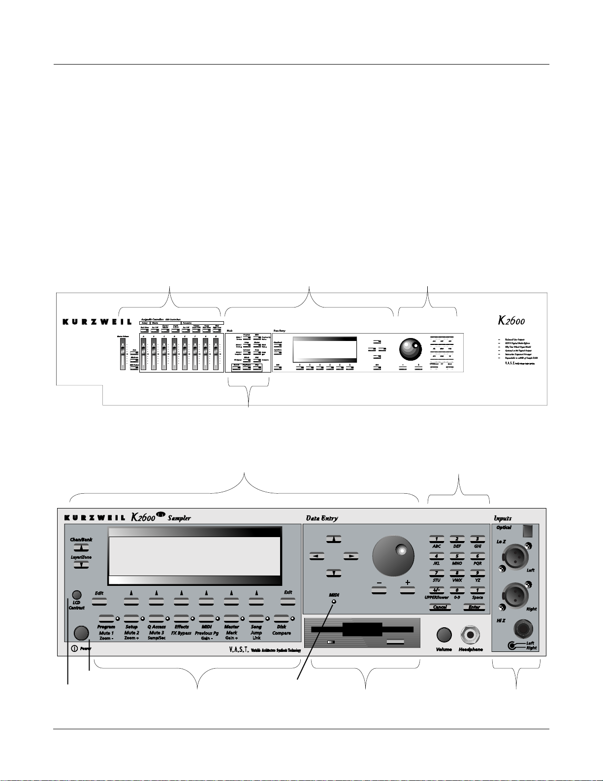
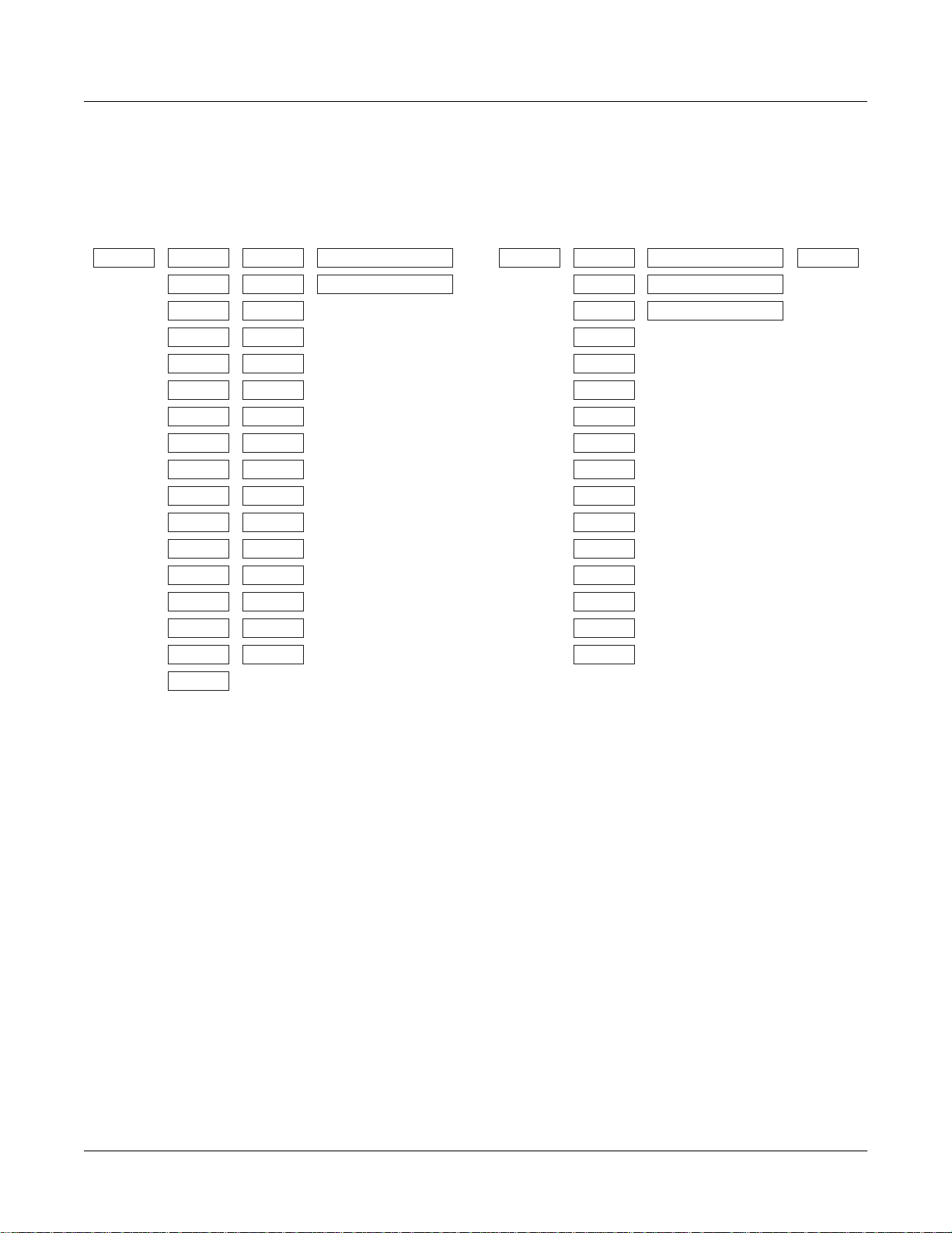
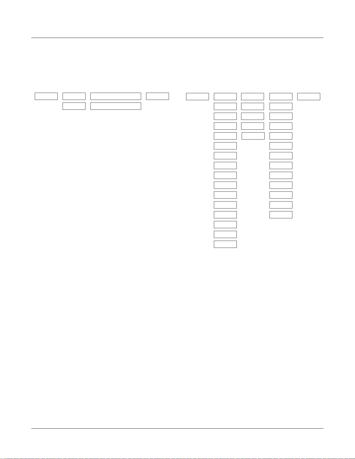
Front Panel Quick Reference
This section describes features that, unless speciÞed otherwise, are common to both the rack
versions of the K2600 (K2600R and K2600RS) as well as the keyboard versions of the K2600
(K2600, K2600S, K2600X, and K2600XS). The buttons and sliders that are unique to the keyboard
models are described on page 1-4.
Control
Navigation Data Entry
Front Panel
Front Panel Quick Reference
Power switch
LCD contrast
Mode Selection
Navigation Data Entry
Mode Selection
MIDI LED
Disk Drive
Audio Inputs
1-1
Page 10
Front Panel
Front Panel Quick Reference
Volume Knob/ Slider
Controls mixed audio outputs and headphone jack only. Does not send MIDI Volume (MIDI 07).
Mode Buttons
Press any of these eight buttons to enter the corresponding mode.
Chan/Bank Buttons
Scroll through the layers of the current program while in the Program Editor. Scroll through the
zones in the current setup while in Setup mode. Scroll through the Quick Access banks while in
Quick Access mode.
Edit Button
Functional in most modes. Press Edit to modify the currently selected object or parameter. If itÕs
not editable, pressing Edit will do nothing.
There are editors available from every mode but Disk mode. The effect of pressing Edit in each
of the modes is listed below.
When in this
mode
Program mode …enters the Program Editor, where you can edit the currently selected
program. Chapter 6 in the
Setup mode …enters the Setup Editor, where you can edit the currently selected setup.
Chapter 7 in the
Quick Access mode …enters the Quick Access Editor, where you can change the program or
setup assigned to the bank slot that was selected when you entered the
Quick Access Editor. See Chapter 8 in the
Effects mode …if the Studio parameter is highlighted, enters the Studio Editor, where y ou
can edit the currently selected studio. Chapters 9 and 15 in the
Guide
explain studios, the Studio Editor, FX presets, and the FX Preset
Editor.
MIDI mode …enters the Velocity Map or Pressure Map Editor if the Velocity or
Pressure Map parameter is selected on either the TRANSMIT page or the
RECEIVE page. See Chapter 18 in the
Program Editor if the Program parameter is selected on the CHANLS page.
See Chapter 6 in the
Master mode …enters the Velocity Map, Pressure Map, or Intonation Table Editor if the
VelTouch, PressTouch, or Intonation parameter is selected. See
Chapter 18 in the
Song mode …enters the Song Editor. The Song Editor is discussed in Chapter 12 in the
Musician’s Guide
parameter is highlighted when Edit is pressed.
Disk mode …has no effect.
Pressing the Edit button…
Musician’s Guide
Musician’s Guide
Musician’s Guide
Musician’s Guide
. Takes you to the Program Editor if the Program
describes the Setup Editor.
.
covers the Program Editor.
Musician’s Guide
Musician’s Guide
.
. Takes you to the
.
Musician’s
1-2
Table 1-1 Navigating with the Edit Button
Page 11

Soft Buttons
Functions change depending on current display page. Function of each button is displayed on
bottom line of display.
Exit Button
Press to leave various editors. If youÕve made any changes while in the editor, you will be
prompted to save them.
Cursor Buttons
Press the corresponding button to move the cursor up, down, left, or right in the display.
Different parameter values will be highlighted as buttons are pressed.
Alpha Wheel
For data entry. Rotate clockwise to increase value of currently selected parameter,
counterclockwise to decrease.
Plus / Minus Buttons (- and +)
Under the Alpha Wheel. Press to increase or decrease the value of the currently selected
parameter by the smallest possible amount. DonÕt confuse this with the +/- button on the
alphanumeric buttonpad.
Front Panel Quick Reference
Front Panel
Alphanumeric Buttonpad
For Numeric Characters
Enter the value numerically instead of using the Alpha Wheel or Plus / Minus buttons. Press
Enter when Þnished. Press Cancel to restore a parameter to its previous value. Pressing Clear is
equivalent to pressing 0 without pressing Enter .
For Alphabetic Characters
When naming objects, you can use the alphanumeric pad to enter letters instead of numbers. If
youÕre renaming a program, for example, just position the cursor under the character you want
to change, then press the corresponding numeric button, as labeled. Press the button as many
times as necessary to enter the desired character. Pressing Clear will enter a space before the
selected character. The 0 button will enter the numerals 0Ð9 when pressed repeatedly.
HereÕs an example. To enter the letter C in a blank space, press 1 three times. You can press the
+/- button before or after entering the letter.
The Cancel button is equivalent to the >>> soft button, and Enter is the same as OK . The Clear
button replaces the currently selected character with a space. The +/Ð button toggles between
uppercase and lowercase letters.
When you press the +/Ð button on the alphanumeric pad, the currently selected character (the
one with the cursor under it) will switch from upper case to lower case, and vice versa. The +/Ð
button is a toggle; that is, if you switch from lower to upper case, all further entries will be in
upper case until you press the +/Ð button again.
1-3
Page 12
Front Panel
Special Keyboard Functions
There are several punctuation characters available as well, but they can be entered only with the
Alpha Wheel or Plus/Minus buttons. The punctuation characters are between z (lower case)
and 0.
Special Alphanumeric Buttonpad Functions
When youÕre in Quick Access mode, the Alphanumeric buttonpad can be used to select the
entries in the current Quick Access bank. The layout of the alphanumeric buttonpad
corresponds to the layout of Quick Access bank entries as seen on the Quick Access-mode page.
ThereÕs also a shortcut for selecting different QA banks while in QA mode. Just press the +/Ð or
Clear button on the alphanumeric pad, and youÕll be prompted to enter a bank number. Type
the desired number on the alphanumeric pad, then press Enter. The bank will be selected, and
youÕll return to the Quick Access page.
You can also use the alphanumeric pad to select strings to search for in the currently selected list
of objects, and to enter new strings to search for. The search function is described fully on
page 3-8 of the MusicianÕs Guide.
Lastly, rack users can play notes from the numeric keypad by holding down the Cancel button
while pressing alphanumeric buttons. This is described fully on page 3-10 of the MusicianÕs
Guide.
The Display
You may want to adjust the contrast of the display for different lighting conditions. On keyboard
models, the adjustment knob is on the rear panel, between the MIDI ports and the continuous
controller pedal jacks. On rack models, itÕs on the front panel, above the power switch.
MIDI LED (Rack Models Only)
Lights when the K2600 is receiving MIDI information at its MIDI In port.
Special Keyboard Functions
This section describes the buttons and sliders that are unique to the keyboard models of the
K2600. Features common to both rack and keyboard models are described starting on page 1-1.
Programmable controllers:
Sliders A–H, and the buttons
above them,
Pitch Wheel and Mod Wheel
Panel switches (Buttons 9 and 10)
Large and small ribbons
Two continuous control pedals (or
one pedal and one breath
controller)
Four foot switches
1-4
Page 13
Solo Button
Mutes all zones in setup except the current one. The button of the zone being soloed glows red.
Mixdown Button
Brings up the Mixdown page, as shown in the following diagram. From this page you can
choose how the K2600Õs physical sliders function during MIDI mixdown. In the example below,
Sliders A-H will control the volume level of MIDI channels 1-8. By pressing the Pan soft button,
you would change the function of the sliders to control panning for channels 1-8; or, you could
press the 9-16 soft button to have the sliders affect channels 9-16.
You can also use the cursor buttons to highlight the pan or volume control for a channel and use
the Alpha Wheel or Plus/Minus buttons to change the pan or volume level. In the screen below,
for example, you could use the Alpha Wheel to control panning on channel 9 at the same time
that you are using the sliders to control volume on channels 1-8.
Front Panel
Special Keyboard Functions
Shows whether
physical sliders
control pan or
volume.
Mixdown||||<>Prog:|36|DuckWalk||||||||||
|||WXWXWXWX|WXWXWXWX|WXWXWXWX|WXWXWXWX||
|||wxwxC{wx|wxwxwxwx|wxwxwxwx|wxwxwxwx||
>>||z|z}~|z||z|z|z|z||z|z|z|z||z|z|z|z||
||||_|_|_|_||_|_|_|_||_|_|_|_||_|_|_|_||
||||||||||||||||||||||||||||||||||||||||
|||*****************||||||||||||||||||||
|Pan|||Volume|Ch|1-8|Ch9-16|||||||||Done
Shows which channels are affected
by physical sliders.
Figure 1-1 Mixdown Control
MIDI Faders button
When you press the MIDI Faders button, the K2600Õs sliders take on the functions assigned on
the current MIDI Faders page. From the MIDI Faders display you can deÞne four different pages
that deÞne how the K2600Õs physical sliders will work. In the display shown below, for example,
the eight sliders are each deÞned to send MIDI 6 (Data) on Channels 9 through 16. Press one of
the Page soft buttons to use (or create) a different page of MIDI fader assignments. Use the Send
soft button to transmit values without moving the faders.
The MIDI Faders pages is saved as part of the Master table object.
Soft buttons for indicating
which channels are affected
by physical sliders.
MIDI|Faders:Page2|||||||||||||||||||||||
Chan|:|9|||10||11||12|||13|||14||15||16|
Ctl||:|6|||6|||6|||6||||6||||6|||6|||6||
Value:|0|||0|||0|||0||||0||||0|||0|||0||
||||||||||||||||||||||||||||||||||||||||
||||||\]||}~||\]||}~||||\]||}~||\]||}~||
|||||||_|||_|||_|||_|||||_|||_|||_|||_||
Page1||Page2||Page3||Page4|||Send|||Done
1-5
Page 14

Front Panel
Special Button Functions
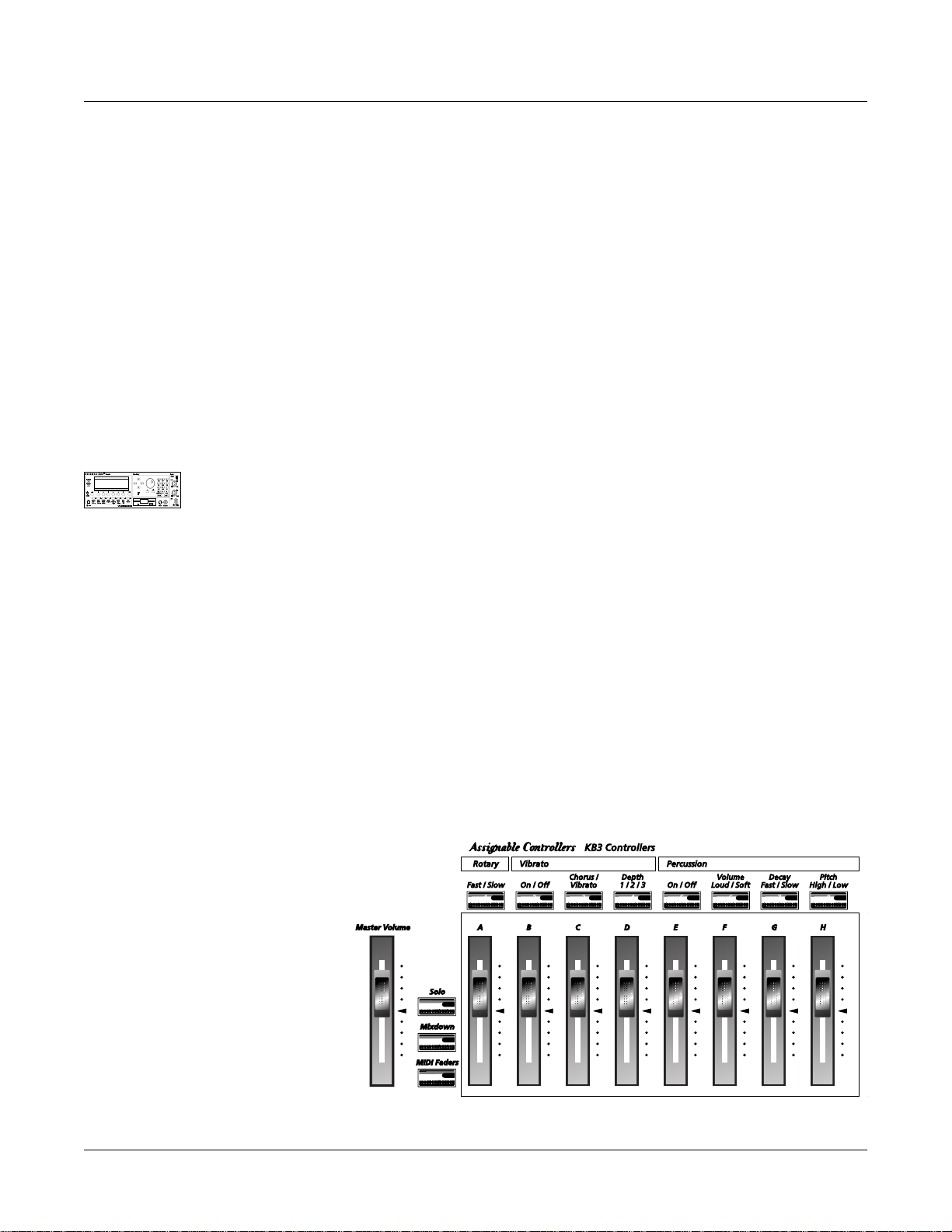
Assignable Controllers (Buttons 1–8 and Sliders A–H)
The function of these controllers will depend on how theyÕve been deÞned within a setup.
Buttons 1Ð8 control either zone muting or KB3 features, depending on the value of the value of
the Mutes parameter on the COMMON page in the Setup Editor. The SLIDER and SLID/2 pages
conÞgure the functions of Sliders AÐH.
PSw1, PSw2 (Buttons 9 and 10)
The function of these controllers depends on how theyÕve been deÞned on the SWITCH page in
the Setup Editor.
Record, Play/Pause, Stop
These buttons duplicate the functions of the corresponding soft buttons in Song mode, allowing
you to conveniently record, play, pause, and stop the current song.
Special Button Functions
The Mode buttons and the Chan/Bank Down button have additional functions, depending on
the mode or editor youÕre in. When youÕre in the Program or Setup Editor, they function
according to the blue labeling under each button. They also work as track mutes on the MIX
page of Song mode.
When youÕre in the Sample Editor, the Program, Setup, Q Access, MIDI, Master, and Song
mode buttons function according to the orange labeling near each button. Table 1-2 describes all
of the special button functions. This table also appears as Table 5-1 on page 5-8 of the MusicianÕs
Guide.
Button Mode or Editor
White
Blue
Orange
Program
Mute 1
Zoom-
Setup
Mute 2
Zoom+
Q Access
Mute 3
Samp / Sec
Effects
FX Bypass
Program Editor (Blue) Setup Editor (Blue) Song Mode
Mutes Layer 1 of current program, or
mutes current layer of current drum
program
Mutes Layer 2 of current program, or
solos current layer of current drum
program
Mutes Layer 3 of current program, or
solos current layer of current drum
program
Bypasses (mutes) current program’s FX
preset (plays program dry)
Mutes Zone 1 of current
setup if 3 or fewer zones;
mutes current zone of
current setup if more than 3
zones
Mutes Zone 2 of current
setup if 3 or fewer zones;
solos current zone of
current setup if more than 3
zones
Mutes Zone 3 of current
setup if 3 or fewer zones;
solos current zone of
current setup if more than 3
zones
Bypasses (mutes) current
setup’s studio (plays studio
dry)
On MIX page,
mutes T rack 1
or 9
On MIX page,
mutes T rack 2
or 10
On MIX page,
mutes T rack 3
or 11
On MIX page,
mutes T rack 4
or 12
Sample Editor
(Orange)
On TRIM and LOOP
pages, decreases
horizontal dimension of
current sample in
display
On TRIM and LOOP
pages, increases
horizontal dimension of
current sample in
display
Toggles between units
used to identify location
within sample— either
number of samples from
start, or time in seconds
from start
1-6
Table 1-2 Special Button Functions
Page 15

Button Mode or Editor
Front Panel
Special Button Functions
White
Blue
Orange
MIDI
Previous Pg
Gain -
Master
Mark
Gain +
Song
Jump
Link
Disk
Compare
Chan / Bank
Layer / Zone
Edit Whenever cursor is highlighting an editable object or parameter, takes you to corresponding editor or programming page
Program Editor (Blue) Setup Editor (Blue) Song Mode
Successive presses take you back to
four most recent editor pages; 5th press
takes you to ALG page
“Remembers” current editor page, so
you can recall multiple pages with Jump
button; asterisk appears before page
name to indicate that it’s marked;
unmark pages by pressing Mark when
page is visible
Jumps to marked pages in order they
were marked
Negates effect of unsaved edits and
plays last-saved (unedited) version of
object being edited
In Program Editor, these two buttons scroll through layers of current
program; in Effects Editor, scroll through FX presets; in Keymap Editor,
scroll through velocity levels of current keymap; in Setup Editor, scroll
through zones of current setup; in Quick Access mode, scroll through
entries in current Quick Access bank
Successive presses take
you back to four most
recent editor pages; 5th
press takes you to CH/PRG
page
Same as for Program
Editor; pages common to
both editors are marked or
unmarked for
Jumps to marked pages in
order they were marked
Same as for Program
mode; display reminds you
that you’re comparing;
press any button to return
to edited version
both
editors
On MIX page,
mutes T rack 5
or 13
On MIX page,
mutes T rack 6
or 14
On MIX page,
mutes T rack 7
or 15
On MIX page,
mutes T rack 8
or 16
Change
recording
track
Sample Editor
(Orange)
On TRIM and LOOP
pages, decreases
vertical dimension of
current sample in
display
On TRIM and LOOP
pages, increases
vertical dimension of
current sample in
display
Preserves interval
between Start, Alt,
Loop, and End points of
current sample; press
again to unlink
Table 1-2 Special Button Functions (Continued)
1-7
Page 16
Front Panel
Special Button Functions: Double Button Presses
Special Button Functions: Double Button Presses
Pressing two or more related buttons simultaneously executes a number of special functions
depending on the currently selected mode. Make sure to press them at exactly the same time.
The following table also appears as Table 3-1 on page 3-6 of the MusicianÕs Guide.
In this
mode or
editor…
Program
mode
Master mode Chan/Bank Enables Guitar/Wind Controller mode.
Song mode
Disk mode
Program
Editor
Keymap
Editor
Sample
Editor
Any Editor
Save Dialog Plus/Minus buttons Toggle between next free ID and original ID.
…pressing these buttons
simultaneously…
Octav-, Octav+ Reset MIDI transposition to 0 semitones. Doub le-press again to
go to previous transposition.
Chan–, Chan+ Set current MIDI channel to 1.
Plus/Minus Step to next Program bank (100, 200, etc.)
Left/Right cursor buttons Toggle between Play and Stop.
Up/Down cursor buttons Toggle between Play and Pause.
Chan/Bank Select all tracks on any TRACK page in Song Editor.
2 leftmost soft buttons Issue SCSI Eject command to currently selected SCSI device.
Chan/Bank Hard format SCSI device. List selected objects when saving
objects.
Left/Right cursor buttons Select all items in a list. Move cursor to end of name in naming
dialog.
up/down cursor buttons Clear all selections in a list. Move cursor to beginning of name
in naming dialog.
Chan/Bank Select Layer 1.
Plus/Minus With cursor on the Coarse Tune parameter, toggles between
default Coarse Tune of sample root and transposition of sample
root.
2 leftmost soft buttons Toggle between default zoom setting and current zoom setting.
Plus/Minus buttons Set the value of the currently selected parameter at the next
zero crossing.
Plus/Minus Scroll through the currently selected parameter’s list of v alues in
regular or logical increments (varies with each parameter).
2 leftmost soft buttons Reset MIDI transposition to 0 semitones. Doub le-press again to
go to previous transposition.
Center soft buttons Select Utilities menu (MIDIScope, Stealer, etc.).
2 rightmost soft buttons Sends all notes/controllers off message on all 16 channels
(same as Panic soft button).
Left/Right cursor buttons Toggle between Play and Stop of current song.
Up/Down cursor buttons Toggle between Play and Pause of current song.
…does this:
1-8
Table 1-3 Double Button Presses
Page 17
Chapter 2
LFOs
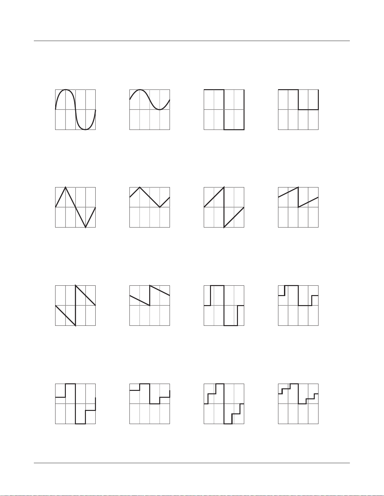
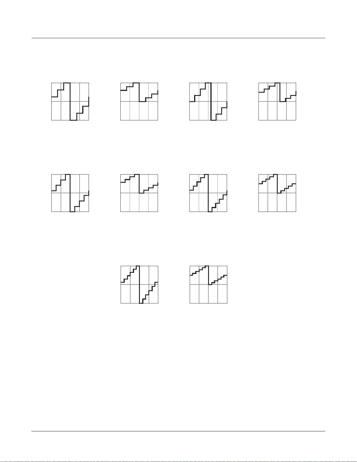
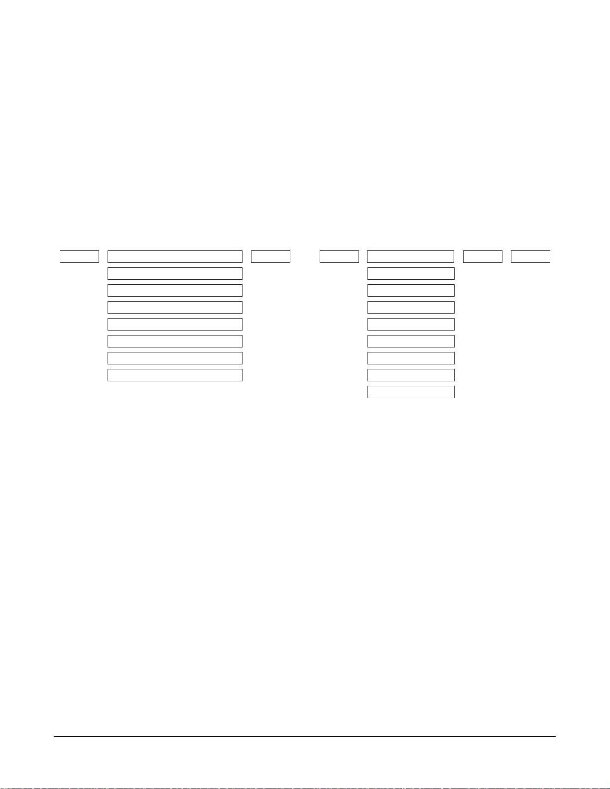
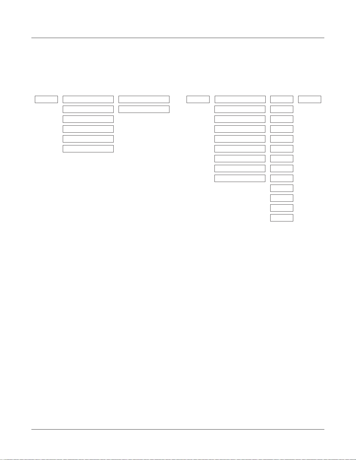
LFO Shapes
Sine Sine
Positive Sine +Sine
Square Square
Positive Square +Squar
Triangle Triang
Positiv e Triangle +T rian
Rising Sawtooth Rise S
Positive Rising Sawtooth +Rise
Falling Sawtooth Fall S
Positive Falling Sawtooth +Fall
3 Step 3 Step
Positive 3 Step +3 Ste
4 Step 4 Step
Positive 4 step +4 Ste
5 Step 5 Step
Positive 5 Step +5 Ste
6 Step 6 Step
Positive 6 Step +6 Ste
7 Step 7 Step
Positive 7 Step +7 Ste
8 Step 8 Step
Positive 8 Step +8 Ste
10 Step 10 Ste
Positive 10 Step +10 St
12 Step 12 Ste
Positive 12 Step +12 St
LFOs
LFO Shapes
LFO Shape Displayed As
2-1
Page 18
LFOs
LFO Shapes
Sine
+1
-1
90°
0° 360° / 0°
+1
-1
90°
0° 360° / 0°
270°
180°
Triangle
270°
180°
Positive Sine
+1
-1
90°
0° 360° / 0°
Positive Triangle
+1
-1
90°
0° 360° / 0°
270°
180°
270°
180°
Sq uare
+1
-1
90°
0° 360° / 0°
Rising Sawtooth
+1
-1
90°
0° 360° / 0°
270°
180°
270°
180°
Positive Sq uare
+1
-1
90°
0° 360° / 0°
Positive Rising Sawtooth
+1
-1
90°
0° 360° / 0°
270°
180°
270°
180°
Falling Sawtooth
+1
-1
90°
0° 360° / 0°
+1
-1
90°
0° 360° / 0°
270°
180°
4 Step
270°
180°
Positive Falling Sawtooth
+1
-1
90°
0° 360° / 0°
Positive 4 Step
+1
-1
90°
0° 360° / 0°
270°
180°
270°
180°
3 Step
+1
-1
90°
0° 360° / 0°
+1
-1
90°
0° 360° / 0°
270°
180°
5 Step
270°
180°
Positive 3 Step
+1
-1
90°
0° 360° / 0°
Positive 5 Step
+1
-1
90°
0° 360° / 0°
270°
180°
270°
180°
2-2
Page 19
LFOs
LFO Shapes
6 Step
+1
-1
90°
0° 360° / 0°
+1
-1
90°
0° 360° / 0°
270°
180°
8 Step
270°
180°
6 Step
Positive Sine
+1
-1
90°
0° 360° / 0°
Positive 8 Step
+1
-1
90°
0° 360° / 0°
270°
180°
270°
180°
7 Step
+1
-1
90°
0° 360° / 0°
+1
-1
90°
0° 360° / 0°
270°
180°
10 Step
270°
180°
Positive 7 Step
+1
-1
90°
0° 360° / 0°
Positive 10 Step
+1
-1
90°
0° 360° / 0°
270°
180°
270°
180°
12 Step
+1
-1
90°
270°
180°
0° 360° / 0°
Positive 12 Step
+1
-1
90°
0° 360° / 0°
270°
180°
2-3
Page 20

Page 21
Chapter 3
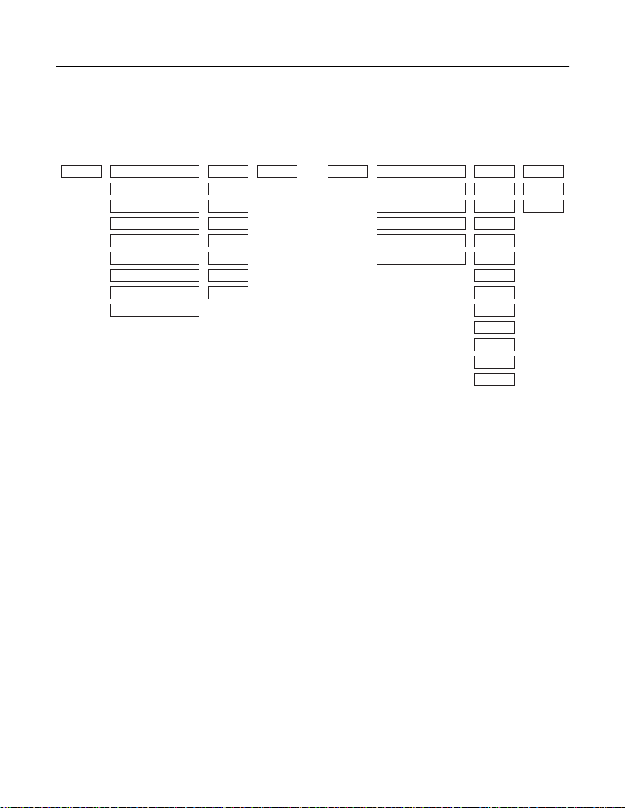
DSP Algorithms
Algorithm|1||||||||||||||||||||||||||||||
|||||||||||||||||||||||||||||||||||||||||
errR®rrterrR®rrrrrrR®rrrrrrR®rrterrR®rrt|
d||||||gk||||||||||||||||||||||gk||||||gh
cvvvvvvbcvvvvvvvvvvvvvvvvvvvvvvbcvvvvvvb|
PITCH HIFREQ STIMULATOR
PARAMETRIC EQ
STEEP RESONANT BASS
4POLE LOPASS W/SEP
4POLE HIPASS W/SEP
TWIN PEAKS BANDPASS
DOUBLE NOTCH W/SEP
NONE
AMP
Algorithm|2||||||||||||||||||||||||||||||
|||||||||||||||||||||||||||||||||||||||||
errR®rrterrR®rrrrrrR®rrterrR®rrtYrrR®rrty
d||||||gk||||||||||||||gk||||||G;||||||GH
cvvvvvvbcvvvvvvvvvvvvvvbcvvvvvvbNvvvvvvbn
PITCH
2PARAM SHAPER
2POLE LOWPASS
BANDPASS FILT
NOTCH FILTER
2POLE ALLPASS
PARA BASS
PARA TREBLE
PARA MID
NONE
AMPPANNER
Page 22
DSP Algorithms
Algorithm|3||||||||||||||||||||||||||||||
|||||||||||||||||||||||||||||||||||||||||
errR®rrterrR®rrrrrrR®rrtyrrR®rrrrrrR®rrty
d||||||jk||||||||||||||u:||||||||||||||GH
cvvvvvvm,..............M/vvvvvvvvvvvvvvbn
PITCH
2POLE LOWPASS
AMP U AMP L2PARAM SHAPER
BAL AMP
BANDPASS FILT
NOTCH FILTER
2POLE ALLPASS
NONE
Algorithm|4||||||||||||||||||||||||||||||
|||||||||||||||||||||||||||||||||||||||||
errR®rrterrR®rrrrrrR®rrterrR®rrterrR®rrt|
d||||||gk||||||||||||||gk||||||gk||||||gh
cvvvvvvbcvvvvvvvvvvvvvvbcvvvvvvbcvvvvvvb|
PITCH AMP
2PARAM SHAPER LPCLIP
2POLE LOWPASS
BANDPASS FILT
NOTCH FILTER
2POLE ALLPASS
PARA BASS
PARA TREBLE
PARA MID
NONE
SINE+
NOISE+
LOPASS
HIPASS
ALPASS
GAIN
SHAPER
DIST
SW+SHP
SAW+
SW+DST
NONE
3-2
Page 23
DSP Algorithms
Algorithm|5||||||||||||||||||||||||||||||
|||||||||||||||||||||||||||||||||||||||||
errR®rrterrR®rrrrrrR®rrterrR®rrterrR®rrt|
d||||||gk||||||||||||||gk||||||gk||||||gh
cvvvvvvbcvvvvvvvvvvvvvvbcvvvvvvbcvvvvvvb|
PITCH AMP
2PARAM SHAPER
2POLE LOWPASS
BANDPASS FILT
NOTCH FILTER
2POLE ALLPASS
PARA BASS
PARA TREBLE
PARA MID
LP2RES
SHAPE2
BAND2
NOTCH2
LOPAS2
HIPAS2
LPGATE
NONE
NONE
Algorithm|6||||||||||||||||||||||||||||||
|||||||||||||||||||||||||||||||||||||||||
errR®rrterrR®rrrrrrR®rrterrR®rrtYrrR®rrt|
d||||||jk||||||||||||||gk||||||u:||||||gh
cvvvvvvm,..............M,......M/vvvvvvb|
PITCH
2PARAM SHAPER LPCLIP
2POLE LOWPASS
BANDPASS FILT
NOTCH FILTER
2POLE ALLPASS
NONE
SINE+
NOISE+
LOPASS
HIPASS
ALPASS
x AMP
+ AMP
! AMP
GAIN
SHAPER
DIST
SW+SHP
SAW+
SW+DST
NONE
3-3
Page 24
DSP Algorithms
Algorithm|7||||||||||||||||||||||||||||||
|||||||||||||||||||||||5rrrrrrrr6||||||||
errR®rrterrR®rrrrrrR®rrTerrR®rrt7rrR®rrt|
d||||||jk||||||||||||||u?||||||i;||||||gh
cvvvvvvm,..............M/vvvvvvbNvvvvvvb|
PITCH
2PARAM SHAPER LPCLIP
2POLE LOWPASS
BANDPASS FILT
NOTCH FILTER
2POLE ALLPASS
NONE
SINE+
NOISE+ ! AMP
LOPASS
HIPASS
ALPASS
x AMP
+ AMP
GAIN
SHAPER
DIST
SINE
LF SIN
SW+SHP
SAW+
SW+DST
NONE
Algorithm|8||||||||||||||||||||||||||||||
|||||||||||||||||||||||||||||||||||||||||
errR®rrterrR®rrterrR®rrterrR®rrterrR®rrt|
d||||||gk||||||gk||||||gk||||||gk||||||gh
cvvvvvvbcvvvvvvbcvvvvvvbcvvvvvvbcvvvvvvb|
PITCH LOPASS
HIPASS
ALPASS
GAIN
SHAPER
DIST
PWM
SINE
LF SIN
SW+SHP
SAW+
SAW
LF SAW
LOPASS
HIPASS
ALPASS
GAIN
SHAPER
DIST
SW+SHP
SAW+
WRAP
NONE
AMPLPCLIP
SINE+
NOISE+
LOPASS
HIPASS
ALPASS
GAIN
SHAPER
DIST
SW+SHP
SAW+
SW+DST
NONE
SQUARE
LF SQR
WRAP
NONE
3-4
Page 25
DSP Algorithms
Algorithm|9||||||||||||||||||||||||||||||
|||||||||||||||||||||||||||||||||||||||||
errR®rrterrR®rrterrR®rrterrR®rrterrR®rrt|
d||||||gk||||||gk||||||gk||||||gk||||||gh
cvvvvvvbcvvvvvvbcvvvvvvbcvvvvvvbcvvvvvvb|
PITCH AMPLOPASS
HIPASS
ALPASS
GAIN
SHAPER
DIST
PWM
SINE
LF SIN
SW+SHP
LOPASS
HIPASS
ALPASS
GAIN
SHAPER
DIST
SW+SHP
SAW+
WRAP
NONE
LP2RES
SHAPE2
BAND2
NOTCH2
LOPAS2
HIPAS2
LPGATE
NONE
SAW+
SAW
LF SAW
SQUARE
LF SQR
WRAP
NONE
Algorithm|10|||||||||||||||||||||||||||||
|||||||||||||||5rrrrrrrr6||||||||||||||||
errR®rrterrR®rrTerrR®rrt7rrR®rrtYrrR®rrt|
d||||||jk||||||u?||||||JU||||||u:||||||gh
cvvvvvvm,......M/vvvvvvm,......M/vvvvvvb|
PITCH LOPASS
HIPASS
ALPASS
GAIN
SHAPER
DIST
PWM
SINE
LF SIN
SW+SHP
SAW+
SAW
LF SAW
SQUARE
LF SQR
WRAP
LOPASS
HIPASS
ALPASS
GAIN
SHAPER
DIST
SINE
LF SIN
SW+SHP
SAW+
SAW
LF SAW
SQUARE
LF SQR
WRAP
NONE
LPCLIP
SINE+
x AMP
+ AMP
NOISE+ ! AMP
LOPASS
HIPASS
ALPASS
GAIN
SHAPER
DIST
SW+SHP
SAW+
SW+DST
NONE
NONE
3-5
Page 26
DSP Algorithms
Algorithm|11|||||||||||||||||||||||||||||
|||||||||||||||5rrrrrrrr6||||||||||||||||
errR®rrterrR®rrTerrR®rrt7rrR®rrtYrrR®rrt|
d||||||gk||||||fk||||||jU||||||u:||||||gh
cvvvvvvbcvvvvvvbcvvvvvvm,......M/vvvvvvb|
PITCH
LOPASS
HIPASS
ALPASS
GAIN
SHAPER
DIST
PWM
SINE
LF SIN
SW+SHP
SAW+
SAW
LF SAW
SQUARE
LF SQR
WRAP
LOPASS
HIPASS
ALPASS
GAIN
SHAPER
DIST
SINE
LF SIN
SW+SHP
SAW+
SAW
LF SAW
SQUARE
LF SQR
WRAP
NONE
LPCLIP
SINE+
x AMP
+ AMP
NOISE+ ! AMP
LOPASS
HIPASS
ALPASS
GAIN
SHAPER
DIST
SINE
LF SIN
SW+SHP
SAW+
SW+DST
NONE
NONE
Algorithm|12|||||||||||||||||||||||||||||
|||||||||||||||||||||||||||||||||||||||||
errR®rrterrR®rrterrR®rrterrR®rrtYrrR®rrt|
d||||||gk||||||jk||||||gk||||||u:||||||gh
cvvvvvvbcvvvvvvm,......M,......M/vvvvvvb|
PITCH LOPASS
HIPASS
ALPASS
GAIN
SHAPER
DIST
PWM
SINE
LF SIN
SW+SHP
SAW+
SAW
LF SAW
SQUARE
LF SQR
WRAP
NONE
LOPASS
HIPASS
ALPASS
GAIN
SHAPER
DIST
PWM
SINE
LF SIN
SW+SHP
SAW+
SAW
LF SAW
SQUARE
LF SQR
WRAP
NONE
LPCLIP
SINE+
NOISE+
LOPASS
HIPASS
ALPASS
GAIN
SHAPER
DIST
SW+SHP
SAW+
SW+DST
NONE
x AMP
+ AMP
! AMP
3-6
Page 27
DSP Algorithms
Algorithm|13|||||||||||||||||||||||||||||
|||||||||||||||||||||||||||||||||||||||||
errR®rrterrR®rrterrR®rrterrR®rrtYrrR®rrty
d||||||gk||||||gk||||||gk||||||G;||||||GH
cvvvvvvbcvvvvvvbcvvvvvvbcvvvvvvbNvvvvvvbn
PITCH AMPPANNERLOPASS
HIPASS
ALPASS
GAIN
SHAPER
DIST
PWM
SINE
LF SIN
SW+SHP
LOPASS
HIPASS
ALPASS
GAIN
SHAPER
DIST
SW+SHP
SAW+
WRAP
NONE
SAW+
SAW
LF SAW
SQUARE
LF SQR
WRAP
NONE
Algorithm|14|||||||||||||||||||||||||||||
|||||||||||||||5rrrrrrrr6||||||||||||||||
errR®rrterrR®rrTerrR®rrt7rrR®rrrrrrR®rrty
d||||||jk||||||u?||||||i;||||||||||||||GH
cvvvvvvm,......M/vvvvvvbNvvvvvvvvvvvvvvbn
PITCH LOPASS
HIPASS
ALPASS
GAIN
SHAPER
DIST
SINE
LF SIN
SW+SHP
SAW+
SAW
LF SAW
SQUARE
LF SQR
WRAP
NONE
LOPASS
HIPASS
ALPASS
GAIN
SHAPER
DIST
SINE
LF SIN
SW+SHP
SAW+
SAW
LF SAW
SQUARE
LF SQR
WRAP
NONE
AMP U AMP L
BAL AMP
3-7
Page 28
DSP Algorithms
Algorithm|15|||||||||||||||||||||||||||||
|||||||||||||||||||||||||||||||||||||||||
errR®rrterrR®rrterrR®rrtYrrR®rrrrrrR®rrty
d||||||gk||||||jk||||||u:||||||||||||||GH
cvvvvvvbcvvvvvvm,......M/vvvvvvvvvvvvvvbn
PITCH LOPASS
HIPASS
ALPASS
GAIN
SHAPER
DIST
PWM
SINE
LF SIN
SW+SHP
SAW+
SAW
LF SAW
SQUARE
LF SQR
WRAP
LOPASS
HIPASS
ALPASS
GAIN
SHAPER
DIST
SINE
LF SIN
SW+SHP
SAW+
SAW
LF SAW
SQUARE
LF SQR
WRAP
NONE
AMP U AMP L
BAL AMP
NONE
Algorithm|16|||||||||||||||||||||||||||||
|||||||||||||||||||||||||||||||||||||||||
errR®rrterrR®rrterrR®rrrrrrR®rrterrR®rrt|
d||||||gk||||||gk||||||||||||||gk||||||gh
cvvvvvvbcvvvvvvbcvvvvvvvvvvvvvvbcvvvvvvb|
PITCH LOPASS
HIPASS
ALPASS
PARA BASS
PARA TREBLE
NONE
AMP
GAIN
SHAPER
DIST
SINE
LF SIN
SW+SHP
SAW+
SAW
LF SAW
SQUARE
LF SQR
WRAP
NONE
3-8
Page 29

DSP Algorithms
Algorithm|17|||||||||||||||||||||||||||||
|||||||||||||||||||||||||||||||||||||||||
errR®rrterrR®rrterrR®rrrrrrR®rrterrR®rrt|
d||||||gk||||||gk||||||||||||||gk||||||gh
cvvvvvvbcvvvvvvbcvvvvvvvvvvvvvvbcvvvvvvb|
PITCH AMPLOPASS
HIPASS
ALPASS
SHAPE MOD OSC
AMP MOD OSC
NONE
GAIN
SHAPER
DIST
PWM
SINE
LF SIN
SW+SHP
SAW+
SAW
LF SAW
SQUARE
LF SQR
WRAP
NONE
Algorithm|18|||||||||||||||||||||||||||||
|||||||||||||||||||||||||||||||||||||||||
errR®rrterrR®rrtYrrR®rrrrrrR®rrterrR®rrt|
d||||||jk||||||u:||||||||||||||gk||||||gh
cvvvvvvm,......M/vvvvvvvvvvvvvvbcvvvvvvb|
PITCH LOPASS
HIPASS
ALPASS
x SHAPEMOD OSC
+ SHAPEMOD OSC
NONE
AMP
GAIN
SHAPER
DIST
SINE
LF SIN
SW+SHP
SAW+
SAW
LF SAW
SQUARE
LF SQR
WRAP
NONE
3-9
Page 30
DSP Algorithms
Algorithm|19|||||||||||||||||||||||||||||
|||||||||||||||||||||||||||||||||||||||||
errR®rrterrR®rrterrR®rrrrrrR®rrterrR®rrt|
d||||||gk||||||gk||||||||||||||gk||||||gh
cvvvvvvbcvvvvvvbcvvvvvvvvvvvvvvbcvvvvvvb|
LOPAS2PITCH AMP
NONE
SHAPE MOD OSC
NONE
Algorithm|20|||||||||||||||||||||||||||||
|||||||||||||||||||||||||||||||||||||||||
errR®rrterrR®rrtYrrR®rrterrR®rrterrR®rrt|
d||||||jk||||||u:||||||gk||||||gk||||||gh
cvvvvvvm,......M/vvvvvvbcvvvvvvbcvvvvvvb|
PITCH LOPASS
HIPASS
ALPASS
GAIN
SHAPER
DIST
SINE
LF SIN
SW+SHP
SAW+
SAW
LF SAW
SQUARE
x GAIN
+ GAIN
XFADE
AMPMOD
NONE
AMPLPCLIP
SINE+
NOISE+
LOPASS
HIPASS
ALPASS
GAIN
SHAPER
DIST
SW+SHP
SAW+
SW+DST
NONE
LF SQR
WRAP
NONE
3-10
Page 31

DSP Algorithms
Algorithm|21|||||||||||||||||||||||||||||
|||||||||||||||||||||||||||||||||||||||||
errR®rrterrR®rrtYrrR®rrterrR®rrterrR®rrt|
d||||||jk||||||u:||||||gk||||||gk||||||gh
cvvvvvvm,......M/vvvvvvbcvvvvvvbcvvvvvvb|
PITCH AMPLOPASS
HIPASS
ALPASS
GAIN
SHAPER
DIST
x GAIN
+ GAIN
XFADE
AMPMOD
NONE
LP2RES
SHAPE2
BAND2
NOTCH2
LOPAS2
HIPAS2
LPGATESINE
LF SIN
NONE
SW+SHP
SAW+
SAW
LF SAW
SQUARE
LF SQR
WRAP
NONE
Algorithm|22|||||||||||||||||||||||||||||
|||||||||||||||5rrrrrrrr6||||||||||||||||
errR®rrterrR®rrTYrrR®rrt7rrR®rrtYrrR®rrt|
d||||||jk||||||u:||||||JU||||||u:||||||gh
cvvvvvvm,......M/vvvvvvm,......M/vvvvvvb|
PITCH LOPASS
HIPASS
ALPASS
GAIN
SHAPER
DIST
SINE
LF SIN
SW+SHP
SAW+
SAW
LF SAW
SQUARE
LF SQR
WRAP
x GAIN
+ GAIN
XFADE
AMPMOD
NONE
LPCLIP
SINE+
NOISE+
LOPASS
HIPASS
ALPASS
GAIN
SHAPER
DIST
SINE
LF SIN
SW+SHP
SAW+
SW+DST
NONE
x AMP
+ AMP
! AMP
NONE
3-11
Page 32

DSP Algorithms
Algorithm|23|||||||||||||||||||||||||||||
|||||||||||||||||||||||||||||||||||||||||
errR®rrterrR®rrtYrrR®rrterrR®rrtYrrR®rrt|
d||||||jk||||||u:||||||jk||||||u:||||||gh
cvvvvvvm,......M/vvvvvvm,......M/vvvvvvb|
PITCH LOPASS
HIPASS
ALPASS
GAIN
SHAPER
DIST
SINE
LF SIN
SW+SHP
SAW+
SAW
LF SAW
SQUARE
LF SQR
WRAP
x GAIN
+ GAIN
XFADE
AMPMOD
NONE
LPCLIP
SINE+
NOISE+
LOPASS
HIPASS
ALPASS
GAIN
SHAPER
DIST
SINE
LF SIN
SW+SHP
SAW+
SW+DST
NONE
x AMP
+ AMP
! AMP
NONE
Algorithm|24|||||||||||||||||||||||||||||
|||||||||||||||||||||||||||||||||||||||||
errR®rrterrR®rrtYrrR®rrterrR®rrtYrrR®rrty
d||||||jk||||||u:||||||gk||||||G;||||||GH
cvvvvvvm,......M/vvvvvvbcvvvvvvbNvvvvvvbn
PANNERPITCH LOPASS
AMP
HIPASS
ALPASS
GAIN
SHAPER
x GAIN
+ GAIN
XFADE
AMPMOD
NONE
DIST
SINE
LF SIN
SW+SHP
SAW+
SAW
LF SAW
SQUARE
LF SQR
WRAP
NONE
3-12
Page 33

DSP Algorithms
Algorithm|25|||||||||||||||||||||||||||||
|||||||||||||||5rrrrrrrr6||||||||||||||||
errR®rrterrR®rrTYrrR®rrt7rrR®rrrrrrR®rrty
d||||||jk||||||u:||||||i;||||||||||||||GH
cvvvvvvm,......M/vvvvvvbNvvvvvvvvvvvvvvbn
PITCH AMP U AMP L
LOPASS
HIPASS
ALPASS
GAIN
SHAPER
x GAIN
+ GAIN
XFADE
AMPMOD
NONE
BAL AMP
DIST
SINE
LF SIN
SW+SHP
SAW+
SAW
LF SAW
SQUARE
LF SQR
WRAP
NONE
Algorithm|26|||||||||||||||||||||||||||||
|||||||||||||||||||||||||||||||||||||||||
||||||||errR®rrterrR®rrterrR®rrtYrrR®rrty
||||||||d||||||©d||||||gk||||||G;||||||GH
||||||||cvvvvvvbcvvvvvvbcvvvvvvbNvvvvvvbn
AMPPANNERSYNC M SYNC S
3-13
Page 34

DSP Algorithms
Algorithm|27|||||||||||||||||||||||||||||
|||||||||||||||||||||||||||||||||||||||||
||||||||errR®rrterrR®rrterrR®rrterrR®rrt|
||||||||d||||||©d||||||gk||||||gk||||||gh
||||||||cvvvvvvbcvvvvvvbcvvvvvvbcvvvvvvb|
LPCLIP
AMPSYNC M SYNC S
SINE+
NOISE+
LOPASS
HIPASS
ALPASS
GAIN
SHAPER
DIST
SINE
LF SIN
SW+SHP
SAW+
SW+DST
NONE
Algorithm|28|||||||||||||||||||||||||||||
|||||||||||||||||||||||||||||||||||||||||
||||||||errR®rrterrR®rrterrR®rrterrR®rrt|
||||||||d||||||©d||||||gk||||||gk||||||gh
||||||||cvvvvvvbcvvvvvvbcvvvvvvbcvvvvvvb|
LP2RES
AMPSYNC M SYNC S
SHAPE2
BAND2
NOTCH2
LOPAS2
HIPAS2
LPGATE
NONE
3-14
Page 35

DSP Algorithms
Algorithm|29|||||||||||||||||||||||||||||
|||||||||||||||||||||||5rrrrrrrr6||||||||
||||||||errR®rrterrR®rrTerrR®rrt7rrR®rrt|
||||||||d||||||jd||||||u?||||||i;||||||gh
||||||||cvvvvvvm,......M/vvvvvvbNvvvvvvb|
SYNC M SYNC S LPCLIP
SINE+
x AMP
+ AMP
NOISE+ ! AMP
LOPASS
HIPASS
ALPASS
GAIN
SHAPER
DIST
SINE
LF SIN
SW+SHP
SAW+
SW+DST
NONE
Algorithm|30|||||||||||||||||||||||||||||
|||||||||||||||||||||||||||||||||||||||||
||||||||errR®rrterrR®rrtYrrR®rrtYrrR®rrt|
||||||||d||||||jd||||||G;||||||u:||||||gh
||||||||cvvvvvvm,......ML......M/vvvvvvb|
SYNC M SYNC S
LPCLIP
SINE+
NOISE+
x AMP
+ AMP
! AMP
LOPASS
HIPASS
ALPASS
GAIN
SHAPER
DIST
SINE
LF SIN
SW+SHP
SAW+
SW+DST
NONE
Algorithm|31|||||||||||||||||||||||||||||
|||||||||||||||||||||||||||||||||||||||||
||||||||errR®rrterrR®rrtYrrR®rrrrrrR®rrty
||||||||d||||||jd||||||u:||||||||||||||GH
||||||||cvvvvvvm,......M/vvvvvvvvvvvvvvbn
SYNC M SYNC S
AMP U AMP L
BAL AMP
3-15
Page 36

Page 37

Chapter 4
Control Sources
Control sources are assigned as values for control source parameters, like Src1 and Src2, Depth
Control for Src2, and LFO rate control. Assigning a control source to one of these parameters is
like connecting control source outputs to various inputs on early modular synthesizers. You can
think of each control source parameter as the input to a synthesizer module, and the values for
those parameters as the outputs of modules generating control signals.
For the control sources to have an effect, two things have to happen. First, the control source
must be assigned as the value for (patched to) a control source parameter like Src1. In other
words, for a control source parameter to have an effect, it must be programmed to respond to a
particular control message. Second, the control source must generate a signal. The level of the
control sourceÕs signal determines how much effect it has on the control source parameter to
which itÕs assigned.
In terms of generating signals, there are two types of control sources. The Þrst, which might be
called hardware control sources, require some physical movement to transmit them. The control
source called MWheel (MIDI 01) is probably the most prominent example of this type of control
source. When you move your MIDI controllerÕs Mod Wheel, it sends a Modulation message
(MIDI 01), unless youÕve programmed it to send something else. By default, when the K2600
receives a MIDI 01 message, it responds by sending a control signal to whatever control source is
assigned as the value for the MWhl parameter on the MIDI-mode RECEIVE page. Of course,
you can program the MWhl parameter to send any available control source signal in response to
MIDI 01 messages.
Control Sources
Some of these hardware control sources have physical controls Òhard-wiredÓ to transmit them.
That is, there are certain physical controls that always generate these control signals. Every time
you strike one of your MIDI sourceÕs keys (or pluck a string, or whatever), for example, a
Note On message is generated, along with an Attack Velocity message. So any time you strike a
key, any control source parameter that has AttVel assigned as its value will be affected by the
Attack Velocity message. Similarly, every time you move the physical Pitch Wheel, a PWheel
message is generated. Whether this affects anything depends on whether you have assigned any
control source parameters to respond to the PWheel message (in other words, whether any
control source parameter has PWheel assigned as its value).
In the Setup Editor youÕll Þnd several parameters that correspond to the standard physical
controllers found on many keyboards. These parameters and their default values are listed in
Table C-1 on page C-2. The values you assign for these parameters determine which control
messages will be transmitted to the K2600 and to its MIDI Out port when you move the
corresponding controls on your MIDI source. If you look at the WHEEL page in the Setup
Editor, youÕll see that the parameter called MWhl has a default value of MWheel. You can
interpret this as follows: ÒMoving the Mod Wheel on my MIDI source sends the MWheel
(Modulation, MIDI 01) message to the K2600Õs sound engine, and, if the K2600Õs LocalKbdCh
parameter matches my controllerÕs transmit channel, also sends it to the K2600Õs MIDI Out
port.Ó
If you change the value of the MWhl parameter, the Mod Wheel will no longer send the MWheel
message, and any control source parameter with MWheel assigned as its value will no longer
respond to movement of the Mod Wheel. All of the control assignment parameters in the Setup
Editor can be programmed to send any of the MIDI controller numbers. For example, if you
assign Foot (MIDI 04) as the value for the Press parameter, then generating mono pressure
messages from your MIDI source will send a Foot (MIDI 04) message to the K2600Õs sound
4-1
Page 38

Control Sources
Control Source Lists
engine, and will affect any control source parameter that has Foot assigned as its value. If the
value for the K2600Õs LocalKbdCh parameter matches your MIDI controllerÕs transmit channel,
then in this case the Foot message will be sent to the K2600Õs MIDI Out port as well, when you
generate mono pressure messages from your MIDI controller.
The other type of control source is independent of the movement of physical controls. These
control sources generate their control signals internally, and might be called software control
sources. They either run automatically (like A Clock and RandV1), or theyÕre programmed to
generate their signals according to parameters of their own (as with the LFOs and FUNs). The
software control sources must have some nonzero value set for one or more of their parameters
before theyÕll generate control signals.
To summarize, there are two different cases in which youÕll assign control sources. One, the
transmit case, determines what control message will be sent by a particular physical control. For
example, MWheel is set by default to be transmitted by the Mod Wheel. The other case, the
receive case, determines which control message will activate a particular control source
parameter. For example, if you assign MPress as the value for the Src1 parameter on the PITCH
page in the Program Editor, then that layerÕs pitch will be affected whenever an MPress message
is generated by any physical controller.
Control Source Lists
ThereÕs one long list of control sources stored in the K2600Õs memory, although not all control
sources are available for all control source parameters. With time youÕll become familiar with
the types of control sources available for various control source parameters.
The available list of control sources varies depending on the type of control source parameter
youÕre programming. There are four basic types: MIDI control sources, local control sources,
global control sources, and FUNs.
When youÕre setting the control assignment parameters in the Setup Editor, youÕll see only the
portion of the Control Source list that has values appropriate to MIDI controller messages.
Consequently we refer to this subset of the Main Control Source list as the MIDI Control Source
list.
YouÕll see variations on the Main Control Source list as you program the other control source
parameters. WeÕll explain these variations, but itÕs not important that you memorize each
variation. The lists differ to prevent you from assigning a control source where it would be
ineffective. All you have to do is to scroll through the list of control sources available for any
given control source parameter, and choose from the available values.
If youÕre programming one of the FUNs, youÕll see the Main Control Source list, which includes
almost every control source from the MIDI Control Source list (with the exception of Data Inc,
Data Dec, and Panic, which belong exclusively to the MIDI Control Source list). The list for the
FUNs also includes a set of constant values, that set an unvarying control signal level for one or
both of the FUNÕs inputs.
For most other control source parameters, youÕll see the Main Control Source list (without the
FUN constants and the three special MIDI control sources we mentioned above). There are two
exceptions to this rule, which have to do with global control source parameters. Globals affect
every note in each programÕs layer(s). Consequently they canÕt use local control sources as their
values, since local control sources affect each note independently.
4-2
Page 39

Control Sources
Descriptions of Control Sources
One control source parameters is always global: the Enable parameter on the LAYER page
(Program Editor). When programming this parameter, youÕll see the Main Control Source list
minus the three special MIDI control sources, minus the following local control sources:
Note St VTRIG2
Key St RandV1
KeyNum RandV2
BKeyNum ASR1
AttVel LFO1
InvAVel FUN1
PPress FUN3
BPPress Loop St
RelVel PB Rate
Bi-AVel AtkSt
VTRIG1 Rel St
Finally, if youÕve turned on the Globals parameter on the COMMON page in the Program
Editor, the available values for GLFO2, and the values for GASR2Õs trigger will lack the local
control sources listed above, as well as the three special MIDI control sources and the FUN
constants. The available values for GFUN2 and GFUN4 will exclude the same list of local control
sources, but will include the FUN constants.
Descriptions of Control Sources
This section is organized into two sets of descriptions: the MIDI Control Source list, and the rest
of the control sources. The numeral preceding the name of each control source can be entered on
the alphanumeric pad to select the control source directly (press Enter after typing the numeral).
Many of the MIDI control sources are assigned as default values for the control assignment
parameters in the Setup Editor. WeÕll indicate these assignments as they appear, simply by
mentioning that theyÕre the default control source for a control assignment parameter.
MIDI Control Source List
With a few exceptions, the MIDI control sources correspond to the standard MIDI controller
numbers used by every MIDI device.
128 OFF
This value eliminates the effect of any control source parameter to which itÕs
assigned.
0, 33 Mono Pressure (MPress)
Many of the K2600Õs factory programs are assigned to modify parameters such as
pitch, Þlter cutoff frequency, and depth control when MPress messages are received.
The mono pressure (Press) control assignment parameters in MIDI and Setup
modes are set by default to transmit MPress messages when mono pressure
messages are received from a controller.
4-3
Page 40

Control Sources
MIDI Control Source List
1 MIDI 01 (MWheel)
2 MIDI 02 (Breath)
3 MIDI 03
4 MIDI 04 (Foot)
5 MIDI 05 (PortTim)
Many factory programs are assigned to respond to MWheel messages. The MWhl
parameter in the Setup Editor is set by default to transmit MWheel.
This is the standard MIDI Controller number for continuous control foot pedals. ItÕs
the default value for the CPedal control assignment parameter, so a control pedal on
your MIDI controller which sends MIDI controller 04 messages will send MIDI
controller 04 messages to the K2600 by default.
This is the standard MIDI controller number for portamento time control. The
K2600 always responds to this control message. For any program that has
portamento turned on (on the COMMON page in the Program Editor), MIDI
Portamento Time messages received via MIDI will affect the rate of the programÕs
portamento.
6 MIDI 06 (Data)
MIDI 06 is the standard MIDI controller number for data entry. The Slider A
parameter on the SLIDER page in the Setup Editor is set by default to transmit this
message, and can be used to select programs and edit parameters on MIDI slaves if
your controller can send it.
7 MIDI 07 (Volume)
This is the standard MIDI controller number for volume. The Volume parameter on
the CHANNELS page in MIDI mode will respond to MIDI controller 07 unless the
VolLock parameter is turned on.
8 MIDI 08 (Balance)
9 MIDI 09
10 MIDI 10 (Pan)
MIDI controller 10 is deÞned as Pan control. The Pan parameter on the CHANNELS
page in MIDI mode will respond to MIDI controller 10 unless the PanLock
parameter is turned on.
4-4
Page 41

11 MIDI 11 (Express)
12—14 MIDI 12—14
15 MIDI 15 (AuxBend2)
The K2600 interprets MIDI Controller 15 as AuxBend2, which is assigned by default
to the short ribbon (below the pitch and mod wheels) on keyboard models of the
instrument. A value of 64 is centered.
16—19 MIDI 16—19 (Ctl A—D)
20 MIDI 20
21 MIDI 21 (AuxBend1)
The K2600 interprets MIDI Controller 21 as AuxBend1, which is assigned by default
to the long ribbon (above the keyboard) on keyboard models of the instrument. A
value of 64 is centered.
Control Sources
MIDI Control Source List
22—31 MIDI 22—31
64 MIDI 64 (Sustain)
This is the standard MIDI Controller number for Sustain. The control assignment
parameter FtSw1 is set by default to MIDI Controller 64, so a switch pedal on your
MIDI controller that sends MIDI 64 will send sustain messages to the K2600 by
default. The K2600 will always respond to sustain messages by sustaining currently
active notes.
65 MIDI 65 (PortSw)
This is the standard MIDI Controller number for Portamento Switch. The
Portamento parameter on the COMMON page in the Program Editor always
responds to this controller, and will turn Portamento on for monophonic programs
when the controller signal is at 64 or above. It wonÕt affect polyphonic programs.
66 MIDI 66 (SostPD)
MIDI Controller 66 is deÞned as Sostenuto Switch. The control assignment
parameter FtSw2 is set by default to MIDI Controller 66, so a switch pedal on your
MIDI controller that sends MIDI 66 will send sostenuto messages to the K2600 by
default. The K2600 will always respond to sostenuto messages.
67 MIDI 67 (SoftPd)
This is the standard MIDI Controller number for Soft Pedal. The K2600 will always
respond to Soft pedal messages.
4-5
Page 42

Control Sources
MIDI Control Source List
68 MIDI 68
69 MIDI 69 (FrezPd)
70—74 MIDI 70—74
75 MIDI 75 (LegatoSw)
76—79 MIDI 76—79
80—83 MIDI 80—83 (Ctl E—H)
84—90 MIDI 84—90
The K2600 will always respond to this message. It causes all notes to be frozen at
their current amplitude levels while the function is on.
The K2600 always responds to this message. When a MIDI Controller 75 message
with a value above 64 is received, the K2600 will force polyphonic programs to be
monophonic.
91 MIDI 91 (FXDep)
The MIDI speciÞcation deÞnes this Controller as External Effects Depth. If the
FX Mode parameter is set to Master, and the FX Channel parameter is set to a
speciÞc MIDI channel, the K2600 will respond to this message when it is received on
the FX channel. It responds by adjusting the Wet/Dry mix of the current studio.
92—95 MIDI 92—95
96 MIDI 96 (DataInc)
This is deÞned as Data Increment. ItÕs intended to be assigned to a switch control.
When the control is on (value 127), the currently selected parameterÕs value will be
increased by one increment. This could be assigned to FtSw2, for example, to scroll
through the program list while in Program mode.
97 MIDI 97 (DataDec)
This is deÞned as Data Decrement. ItÕs intended to be assigned to a switch control.
When the control is on (value 127), the currently selected parameterÕs value will be
decreased by one increment.
123 MIDI 123 (Panic)
The K2600 always responds to this message by sending an All Notes Off and All
Controllers Off message on all 16 MIDI channels.
4-6
Page 43

Main Control Source List
This list contains all but the last three control sources in the MIDI Control Source list. It also
contains the following control sources. All are local unless speciÞed as global.
32 Channel State (Chan St)
Chan St refers to whether any notes are currently active on a given MIDI channel.
Chan St switches on whenever a note is started, and switches off when a Note Off
has been received for each current note on that channel, even if notes are sustained.
33 Mono Pressure (MPress)
This is the same as the MPress control source in the MIDI Control Source list, but is
assigned by entering 33 on the alphanumeric pad when used with a parameter that
takes its values from the Main Control Source list.
34 Bipolar Mono Pressure (BMPress)
This control source generates a control signal of -1 when the value of the control to
which itÕs assigned is at its minimum, and +1 when the control is at its maximum.
For example, if you had the MPress control assignment parameter assigned to send
BMPress, and you had Src1 on a program layerÕs PITCH page assigned to BMPress,
with its depth parameter set to 1200 cents, then the layer would be transposed
down an octave when no pressure (value 0) was applied to your controllerÕs keys
(assuming it sends mono pressure). Maximum pressure (value 127) would
transpose the layer up an octave, while a pressure level of 64 would leave the pitch
unchanged.
Control Sources
Main Control Source List
35 Pitch Wheel Message (PWheel)
The K2600 is hard-wired to respond to this message. Any parameter with PWheel
assigned as its value will be affected when your MIDI controllerÕs Pitch Wheel is
moved.
36 Bipolar Mod Wheel (Bi-Mwl)
This control source will always respond to MIDI controller 01 (MWheel). Control
source parameters set to this value will generate control signals of -1 when the MIDI
Controller 01 message value is 0, and will generate a control signal of +1 when the
MIDI Controller 01 message is at 127, scaling all values in between. For example,
you might set Src1 on a program layerÕs PITCH page to a value of Bi-Mwl, and its
depth parameter to 1200 cents. Then as long as the MWhl control assignment
parameter is set to a value of MWheel, your controllerÕs Mod Wheel will be bipolar;
in this case it will bend the layerÕs pitch down as you move the Mod Wheel toward
minimum, and bend the pitch up as you move the Mod Wheel toward maximum.
37 Absolute Value of Pitch Wheel (AbsPwl)
This control source always responds to movement of your MIDI controllerÕs Pitch
Wheel, but makes the Pitch Wheel unipolar. Whereas pulling the Pitch Wheel fully
down usually generates a control signal value of -1, this control source generates a
value of +1 when the Pitch Wheel is pulled fully down.
4-7
Page 44

Control Sources
Main Control Source List
38 Global ASR (GASR2)
39 Global FUN2 (GFUN2)
40 Global LFO (GLFO2)
41 Global LFO Phase (GLFO2ph)
When the Globals parameter on the COMMON page is turned on, ASR2 becomes
global, and is labeled GASR2. The functions of ASRs are explained on page 6-42 of
the MusicianÕs Guide. This control source does not appear in the Control Source list
for parameters whose functions are local.
When the Globals parameter on the COMMON page is turned on, FUN2 becomes
global, and is labeled GFUN2. The functions of FUNs are explained in Chapter 17 of
the MusicianÕs Guide. This control source does not appear in the Control Source list
for parameters whose functions are local.
When the Globals parameter on the COMMON page is turned on, LFO2 becomes
global, and is labeled GLFO2. The functions of LFOs are explained on page 6-40 of
the MusicianÕs Guide. This control source does not appear in the Control Source list
for parameters whose functions are local.
When the Globals parameter on the COMMON page is turned on, LFO2 becomes
global, and is labeled GLFO2. The functions of LFOs are explained on page 6-40 of
the MusicianÕs Guide. This control source does not appear in the Control Source list
for parameters whose functions are local.
42 Global FUN 4 (GFUN4)
When the Globals parameter on the COMMON page is turned on, FUN 4 becomes
global, and is labeled GFUN4. This control source does not appear in the Control
Source list for parameters whose functions are local.
43 Volume Control (VolCtl)
This control source will always respond to MIDI Controller 07 messages. Assign this
value to a parameter when you want MIDI volume messages to affect the
parameter.
44 Pan Control (PanCtl)
This control source always responds to MIDI Controller 10 messages. Assign this
value to a parameter when you want MIDI pan messages to affect the parameter.
45 Balance Control (BalCtl)
This control source will always respond to MIDI Controller 08 messages. Assign this
value to a parameter when you want MIDI balance messages to affect the
parameter.
46 Channel Count (ChanCnt)
This control source keeps track of the total number of active voice channels (how
many notes are playing), and converts the number into a control signal between 0
and +1. The control signalÕs value is 1 when all 48 voice channels are active, and 0
when no voice channels are active.
4-8
Page 45

Control Sources
Main Control Source List
You can use this control source in several ways. One example is to limit the volume
of each note so that you have a more nearly constant volume regardless of how
many notes youÕre playing (this is independent of the effect of attack velocity on
volume). To set this up, you would go to the F4 AMP page in the Program Editor,
and set the Src1 parameter to a value of ChanCnt. Then set the Depth parameter to
a negative value. This will decrease the overall amplitude of each note as you play
more simultaneous notes. This example works best with short-release sounds. ItÕs
great for an organ program, for example.
Channel count is also useful for controlling the modulation applied to a sound. For
example, you may have a sound that you use both as a lead and for rhythm.
Suppose you want a deep vibrato when youÕre soloing, but less vibrato when youÕre
playing chords. Set up the vibrato by using LFO1 as the value for the Src2
parameter on the PITCH page in the Program Editor. Set the MinDpt parameter to
72 cts, and the MaxDpt parameter to 12 cts. Then set the value of the DptCtl
parameter to ChanCnt, and YouÕll get maximum vibrato depth when only one note
is active. (Channel count outputs a control signal of 0 when no notes are playing, so
with only one note playing, its value is near 0, which causes the DptCtl parameter to
generate a value near its minimum: 72 cents in this case.)
If you want to increase the depth of the vibrato as you increase the number of active
notes, set the value of the MaxDpt parameter higher than that of the MinDpt
parameter.
Note: There are no control sources that correspond to the numeric entries 47Ñ54.
55 Sync State (SyncSt)
This unipolar control source responds to MIDI clock messages received from an
external MIDI device. Sync State switches on (+1) at each clock start, and switches
off (0) with each clock stop.
56 A Clock
This is a unipolar square wave that responds to MIDI clock messages. It switches to
+1 and back to 0 with every clock beat. This control source looks Þrst for externally
received MIDI clock messages, and if none is received, it responds to the K2600Õs
internal clock, which is always running. The internal clock speed is set with the
Tempo parameter in Song mode.
57 Negative A Clock (~A Clock)
This is the opposite of A clock, that is, it switches from 0 to +1 with every clock beat
(the square wave is 180 degrees out of phase with that of A Clock).
58 B Clock
This is similar to A Clock, but itÕs bipolarÑit switches from +1 to -1 with every clock
beat.
59 Negative B Clock (~B Clock)
The opposite of B Clock, this bipolar control source switches from -1 to +1 with
every clock beat (the square wave is 180 degrees out of phase with that of B Clock).
4-9
Page 46

Control Sources
Main Control Source List
60, 61 Global Phase 1 and 2 (G Phase 1, G Phase 2)
62, 63 Global Random Variant 1 and 2 (GRandV 1, GRandV 2)
96 Note State (Note St)
These bipolar global control sources are both rising sawtooth waves that rise from 1 to +1 with each MIDI clock beat. Like A Clock and B clock, they look for an
external clock signal, and if none is received, they respond to the K2600Õs internal
clock.
These are also bipolar and global, and generate random control signal values
between -1 and +1 when assigned to a control source parameter. There is a subtle
difference in the randomness of the signals they generate, therefore choosing
between them is a matter of preference.
At any moment, any given note is either on or off; this is its Note State. Note State
can be used as a unipolar control source that responds to each note thatÕs played. It
switches to +1 when the note starts, and stays on as long as the note is held on (by
the sustain pedal, for example), or by holding down the trigger for that note. It
switches to 0 when the note is no longer sustained by any means. For example, if
you play a note, then hold it with the sustain pedal, its Note State is still on (+1)
even if youÕve released the key that triggered the note. As soon as you release the
sustain pedal, the noteÕs Note State switches to off (0), even if it has a long release
and you can still hear the release section of the note.
97 Key State (Key St)
This is a unipolar control source that responds to the motion of your MIDI sourceÕs
keys (or other note trigger). It switches to +1 when a key is pressed, and switches
to 0 when the key is released. Its effect differs from Note State in that when the key
that switched it on is released, it will switch off even if the note is sustained. If
youÕre using a non-keyboard MIDI source, Key State switches to 0 when the
equivalent of a key release is sent.
98 Key Number (KeyNum)
This is a unipolar control source that generates its signal value based on the MIDI
key number of each note triggered. That is, it generates a value of 0 in response to
MIDI key number 0, a value of 64 in response to MIDI key number 64, and so on.
Note that some parameters, such as Enable Sense on the Program Editor Layer
Page, will not accept this parameter. GKeyNum, controller number 129, would be
acceptable however.
99 Bipolar Key Number (BKeyNum)
This is like KeyNum, but generates a signal value of -1 in response to MIDI key
number 0, a value of 0 in response to MIDI key number 64, and a value of +1 in
response to MIDI key number 127.
100 Attack V elocity (AttVel)
This unipolar control source responds to Attack velocity values received at the
K2600Õs MIDI In port. Velocity values of 0 cause it to generate a signal value of 0,
while velocity values of 127 will generate a value of +1. All other velocity values
will result in signal values proportionally scaled between 0 and +1. Note that some
parameters, such as Enable Sense on the Program Editor Layer Page, will not accept
this control source. GAttVel, controller number 130, would be acceptable however.
4-10
Page 47

101 Inverse Attack Velocity (InvAttVel)
This is the opposite of AttVel, generating a signal value of 0 in response to attack
velocity values of 127.
102 Polyphonic Pressure (PPress)
This unipolar control source responds to poly pressure (aftertouch) messages
received via MIDI. It generates a signal value scaled from 0 to +1 based on the poly
pressure value range of 0Ñ127.
103 Bipolar Polyphonic Pressure (BPPress)
This is like PPress, but scales its signal value from -1 to +1.
104 Release Velocity (RelVel)
Also unipolar, this control source scales its signal value from 0 to +1 in response to
release velocity values from 0Ñ127.
105 Bipolar Attack Velocity (Bi-AVel)
This is similar to AttVel, but scales its signal values from -1 to +1.
Control Sources
Main Control Source List
106, 107 Velocity Triggers 1 and 2 (VTRIG1, VTRIG2)
These unipolar control sources are switch controls, that is, they generate signal
values of either 0 or +1. These must be programmed in order to have an effect; their
programming parameters are found on the VTRIG page in the Program Editor.
When a VTRIGÕs Sense parameter is set to normal, it switches to +1 when a note
plays at a dynamic level exceeding the dynamic level set for its Level parameter. See
page 6-44 of the MusicianÕs Guide for more information.
108, 109 Random Variants 1 and 2 (RandV1, RandV2)
These are similar to GRandV1 and GRandV2, but are local, so will affect each
control source parameter independently.
110, 111 ASR1, ASR2
These are programmable envelopes with three segments, Attack, Sustain, and
Release. Their control source signals are unipolar. See page 6-42 of the MusicianÕs
Guide for a thorough explanation.
112, 113 FUN1, FUN2
These generate their control source signals by combining the control signal values
of two programmable inputs, and performing a mathematical function on the
result. Their control signals can be unipolar or bipolar, depending on the control
sources assigned as their inputs. See page 6-43 of the MusicianÕs Guide. FUN2
becomes global (GFUN2) when the Globals parameter on the COMMON page in
the Program Editor is set to On.
114 LFO1
LFO1 can be unipolar or bipolar depending on the value set for the Shape
parameter on its programming page. See page 6-40 of the MusicianÕs Guide.
4-11
Page 48

Control Sources
Main Control Source List
115 LFO1 Phase (LFO1ph)
116 LFO2
117 LFO2 Phase (LFO2ph)
118, 119 FUN3, FUN4
This bipolar control source generates it signal based on the cycle of LFO1. When the
phase of LFO1 is 0 degrees, the signal value of LFO1ph is 0. When the phase of
LFO1 is 90 degrees, the signal value of LFO1ph is 1. When the phase of LFO1 is 180
degrees, the signal value of LFO1ph is 0. When the phase of LFO1 is 270 degrees, the
signal value of LFO1ph is -1.
This functions exactly the same as LFO1, when the Globals parameter is set to Off
(on the COMMON page in the Program Editor). When the Globals parameter is set
to On, LFO2 becomes global (GLFO2).
This functions exactly the same as LFO1ph, responding to the cycle of LFO2.
These function exactly the same as FUNs 1 and 2, when the Globals parameter is set
to Off (on the COMMON page in the Program Editor). When the Globals parameter
is set to On, FUN4 becomes global (GFUN4).
120 Amplitude Envelope (AMPENV)
This programmable unipolar control source lets you vary the effect of a control
source parameter over time. See page 6-35 of the MusicianÕs Guide.
121, 122 Envelopes 2 and 3 (ENV2, ENV3)
These are programmed in the same way as AMPENV, but they can be bipolar.
123 Loop State (Loop St)
This unipolar control source switches to +1 when the currently playing sample
reaches its LoopStart point. If youÕve programmed a sound with a User amplitude
envelope, Loop St will always be on (+1) for that sound. See page 14-17 of the
MusicianÕs Guide for more about sample loops.
124 Sample Playback Rate (PB Rate)
The signal value of this bipolar control source is determined by the sample playback
rate of each note. The playback rate is a function of the amount of transposition
applied to a sample root to play it at the proper pitch for each note. If you trigger a
note where a sample root is assigned, the PB Rate signal value for that note is 0. If
the note is above the sample root, the sample is transposed upward, and its
playback rate is higher than that of the sample root. Consequently the PB Rate
signal value for that note will be positive. If the note is below the sample root, the
PB Rate signal value will be negative.
4-12
125 Attack State (Atk State)
This unipolar control source switches to +1 and back to 0 very quickly with each
note start.
Page 49

126 Release State (Rel State)
This unipolar control source switches to +1 when a note is released, and stays on
until the note has completed its release (faded to silence), then it switches to 0. It
will stay on if a note is sustained, even if its trigger (key, string, whatever) is
released.
127 ON
This generates a constant control signal value of +1.
128 -ON
This generates a constant control signal value of -1 (the numeric entry 128 selects a
value of OFF in the MIDI Control Source list).
129 GKeyNum
Uses the key number (global) to modify whatever it is patched into. Higher notes
will have a very different effect than will lower notes. Users can use this new Source
to control any K2600 parameters, or to scale amplitude or pitch.
130 GAttVel
This is updated every time you strike another key (kind of a multi- trigger function).
Control Sources
Main Control Source List
In addition to enabling (triggering) layers from any controller (works like an on/off
switch), you can set the assigned controllerÕs threshold (value, or range of values
from 0-127), thus deÞning the controllerÕs active range where it will enable the
layer.
For example, you could create a 32-layer nylon guitar in which each layer is
assigned to a different VAST algorithm and each layer is enabled by discrete narrow
velocity ranges. This would produce 32 different sounding layers with 32 cross
switch points emulating a picked guitar where no two attacks are exactly alike. If
the layers' velocity ranges were very close together yet not overlapping, you could
create very subtle nonrepeating changes. This kind of power usually eludes most
sample playback devices, as this technique uses only one layer of polyphony, due to
cross switching versus cross fading.
131, 132 GHiKey, GLoKey
These control sources work the same as GKeyNum except that they track the
highest key currently held and the lowest key currently held respectively. By using
one of these as the only source for pitch tracking, you can create monophonic-like
layers within a polyphonic program.
4-13
Page 50

Control Sources
Constant Control Sources
Constant Control Sources
The remaining control sources are constants, which appear only when youÕre assigning control
sources as inputs for the FUNs. Assigning one of these values Þxes the inputÕs control signal
value at a steady level.
Assigned
Value
133 -0.99 201 0.09
134 -0.98 202 0.10
135 -0.97 203 0.12
136-140 -0.96 to -0.92 204 0.14
141 -0.91 205 0.16
142 -0.90 206-210 0.18 to 0.26
143-145 -0.88 to -0.84 211-215 0.28 to 0.36
146-150 -0.82 to -0.74 216-220 0.38 to 0.46
151-155 -0.72 to -0.64 221-225 0.48 to 0.56
156-160 -0.62 to -0.54 226-230 0.58 to 0.66
161-165 -0.52 to -0.44 231-235 0.68 to 0.76
166-170 -0.42 to -0.34 236-240 0.78 to 0.86
171-175 -0.32 to -0.24 241 0.88
176-180 -0.22 to -0.14 242 0.90
181 -0.12 243 0.91
182 -0.10 244 0.92
183 -0.09 245 0.93
184 -0.08 246-250 0.94 to 0.98
185 -0.07 251 0.99
186-190 -0.06 to -0.02 256 OFF
191 -0.01
192 0.00
193 0.01
194 0.02
195 0.03
196-200 0.04 to 0.08
Corresponding Constant
Assigned
Value
Corresponding Constant
4-14
Note: There are no control sources that correspond to numeric entries 252Ñ254.
Page 51

Keyboard Shortcuts for Control Sources
You can use the keyboard of your MIDI source to choose control sources, since most key numbers
correspond to a value on the Control Source list. If you have a certain control source that you use over
and over (for example, LFO1), this can be the quickest way to enter its value. To do this, highlight a
parameter that uses a value from the Control Source list, hold down Enter, then strike the key
corresponding to the control source you want to choose. LFO1, for example, corresponds to B5.
Control Sources
Keyboard Shortcuts for Control Sources
C-1 to A0
(Below Standard 88-note Keyboard)
C -1
02 - Breath
04 - Foot
06 - Data
07 - Volume
09 - MIDI 09
11 - Expression
12 - MIDI 12
14 - MIDI 14
A0
01 - Mod Wheel
03 - MIDI 03
05 - Portamento Time
08 - Balance
10 - Pan
13 - MIDI 13
15 - MIDI 15
(Standard 88-note Keyboard)
16 - Ctl A
18 - Ctl C
19 - Ctl D
21 - Aux Bend 1
23 - MIDI 23
24 - MIDI 24
26 - MIDI 26
28 - MIDI 28
30 - MIDI 30
31 - OFF
33 - Mono Pressure
35 - Pitch Wheel
36 - Bipolar Mod Wheel
38 - Global ASR (ASR 2)
40 - Global LFO (LFO 2)
42 - Global FUN 2 (FUN 4)
47 - A Clk4
49 - B Clk4
51 - A Clk2
52 - ~A Clk2
54 - –B Clk2
56 - A Clock
58 - B Clock
59 - –B Clk
61 - Global Phase 2
63 - Global Random Variant 2
96 - Note State
98 - Key Number
100 - Attack Velocity
102 - Poly Pressure
103 - Bipolar Poly Pressure
105 - Bipolar Attack Velocity
107- VTRIG 2
108 - Rand Variant 1
110 - ASR 1
112 - FUN 1
114 - LFO 1
115 - LFO 1 Phase
117 - LFO 2 Phase
119 - FUN 4
120 - Amp Envelope
122 - Envelope 3
124 - Sample PB Rate
126 - Release State
127 - ON
129 - GKeyNum
131 - GLowKey
A0 to C8
A0
C4
17 - Ctl B
20 - MIDI 20
22 - MIDI 22
25 - MIDI 25
27 - MIDI 27
29 - MIDI 29
32 - Channel State
34 - Bipolar Mono Pressure
37 - Pitch Wheel Absolute Value
39 - Global FUN (FUN 2)
41 - Global LFO Phase
48 - ~A Clk4
50 - –B Clk4
53 - B Clk2
55 - Sync State
57 - ~A Clk
60 - Global Phase 1
62 - Global Random Variant 1
97 - Key State
99 - Bipolar Key Number
101 - Inverse Attack Velocity
104 - Release Velocity
106 - VTRIG 1
109 - Rand Variant 2
111 - ASR 2
113 - FUN 2
116 - LFO 2
118 - FUN 3
121 - Envelope 2
123 - Loop State
125 - Attack State
128 - GHiKey
130 - GAttVel
C8
4-15
Page 52

Page 53

K2600 Note Numbers and MIDI Note Numbers
Chapter 5
MIDI Note Numbers
K2600 Note Numbers and MIDI Note Numbers
K2600 MIDI
C -1–B -1 0–11
C 0–B 0 12–23
C 1–B 1 24–35
C 2–B 2 36–47
C 3–B 3 48–59
C 4 (Middle C)–B 4 60–71
C 5–B 5 72–83
C 6–B 6 84–95
C 7–B 7 96–107
C 8–B 8 108–119
C 9–G 9 120–127
MIDI Note Numbers
You can assign samples to keymaps in the range from C 0 to G 9. The K2600 will respond to
MIDI events in the octave from C -1 to B -1. If a Note On event is generated in the range from C 1 to B -1, the K2600 will respond by setting the Intonation key correspondingly (C -1 will set it to
C, C# -1 will set it to C#, etc.)
Note Numbers for Percussion Keymaps
Most of the K2600Õs percussion programs have keymaps that place the various percussion
timbres at standardized key locations. There are eight drum keymaps: Preview Drums, Þve
5-octave kits (two dry and three ambient), a 2-octave kit, and the General MIDI kit. The keymap
30 General MIDI Kit adheres as closely as possible to the General MIDI standard for placement
of timbres. As a rule, programs that use this keymap can be assigned in percussion tracks for
prerecorded sequences and will play appropriate timbres for all percussion notes.
The timbres are located consistently within the 5-octave kit keymaps so you can interchange
keymaps within percussion programs freely without changing the basic timbres assigned to
various notes (snare sounds will always be at and around Middle C, for example). The note
assignments for the timbres in the 5-octave kit and 2-octave kit keymaps are listed below. MIDI
note number 60 (Middle C) is deÞned as C 4.
5-1
Page 54

MIDI Note Numbers
Note Numbers for Percussion Keymaps
5-Octave Percussion Keymaps (Range: C2–C7)
MIDI Note Number Key Number Sample Root
36-37
38-39
40-41 E2-F2 Mid Tom
42-43
44-45
46
47–51
52–54
55-56
57-59 A3-B3 Mid Snare (dual vel. on Dry Kit 1)
60-61
62–64 D 4–E 4 Closed HiHat
65–67 F 4–G 4 Slightly Open HiHat
68–69
70–71
72 C 5 Foot-closed HiHat
73-74
75-78
79 G5 Splash Cymbal
80
81-82
83-84 B5-C6 Ride Cymbal (Bell)
85
86 D 6 Handclap
87
88 E 6 Timbale Shell
89 F 6 Conga Tone
90
91 G 6 Conga Slap
92
93 A 6 Clave
94
95–96 B 6–C 7 Tambourine Shake
C2-C
D2-D
#
2-G2
F
#
2-A2
G
#
2
A
B 2–D
E3–F
G3-G
C4-C
#
4–A 4
G
#
4–B 4
A
#
5-D5
C
#
5-F#5
D
#
5
G
A5-A
#
6
C
#
6
D
#
6
F
#
6
G
#
6
A
#
2
#
2
Low Tom
Low Mid Tom
Hi MidTom
Mid Hi Tom
Hi T om
#
3
#
3
#
3
#
4
Kick
Snare (Sidestick)
Low Snare (dual vel. on Dry Kit 1)
Hi Snare (dual vel. on Dry Kit 1)
Open HiHat
Open to Closed HiHat
Low Crash Cymbal
Pitched Crash Cymbals
Ride Cymbal (Rim)
#
5
Ride Cymbal (Rim and Bell)
Cowbell
Timbale
Conga Bass Hi
Conga Bass Low
Cabasa
5-2
Page 55

2-Octave Percussion Keymaps (Range: C3 - C5)
MIDI Note Number Key Number Sample Root
48–49
C 3–C
#
3
50 D 3 Low Tom
51
#
3
D
52 E 3 Low Tom
53 F 3 Mid Tom
54
#
3
F
55 G 3 Mid Tom
56
#
3
G
57 A 3 High Tom
58
#
3
A
59 B 3 High Tom
60-61
C4-C
#
4
62 D 4 Closed HiHat
63
#
4
D
64 E 4 Closed HiHat
65 F 4 Slightly Open HiHat
66
#
4
F
67 G 4 Slightly Open HiHat
68
#
4
G
69 A 4 Open HiHat
70
#
4
A
71 B 4 Open to Closed HiHat
72 C 5 Foot-closed HiHat
Kick
Cowbell
Cowbell
Timbale
Snare (Sidestick)
Snare (dual velocity)
Ride Cymbal (Rim and Bell)
Crash Cymbal
Crash Cymbal
Crash Cymbal
MIDI Note Numbers
Note Numbers for Percussion Keymaps
5-3
Page 56

Page 57

Chapter 6
MIDI, SCSI, and Sample Dumps
SCSI Guidelines
The following sections contain information on using SCSI with the K2600, as well as speciÞc
sections dealing with the Mac and the K2600.
Disk Size Restrictions
The K2600 accepts hard disks with up to 2 gigabytes of storage capacity. If you attach an
unformatted disk that is larger than 2 gigabytes, the K2600 will still be able to format it, but only
as a 2 gigabyte disk. If you attach a formatted disk larger than 2 gigabytes, the K2600 will not be
able to work with it; you could reformat the disk, but thisÑof courseÑwould erase the disk
entirely.
MIDI, SCSI, and Sample Dumps
SCSI Guidelines
Configuring a SCSI Chain
Here are some basic guidelines to follow when conÞguring a SCSI chain:
1. According to the SCSI SpeciÞcation, the maximum SCSI cable length is 6 meters
(19.69 feet). You should limit the total length of all SCSI cables connecting external SCSI
devices with Kurzweil products to 17 feet (5.2 meters). To calculate the total SCSI cable
length, add the lengths of all SCSI cables, plus eight inches for every external SCSI device
connected. No single cable length in the chain should exceed eight feet.
2. The Þrst and last devices in the chain must be terminated. There is a single exception to
this rule, however. A K2600 with an internal hard drive and no external SCSI devices
attached should have its termination disabled. If you later add an external device to the
K2600Õs SCSI chain, you must enable the K2600Õs termination at that time.
ThereÕs a switch on the rear panel of the K2600, which you can use to disable the K2600Õs
termination. We recommend, however, that you leave this switch set to Auto, which
enables the K2600 to switch termination on or off depending on your SCSI conÞguration.
Poor termination is a common cause of SCSI problems. Having more than two terminators
on the bus will overload the bus drivers, but this should not cause permanent damage to
the hardware. Poor termination can corrupt the data on your disk, however, as can bad
SCSI cables.
A note about active termination: The K2600 uses active termination of the SCSI bus.
Active termination has some beneÞts over traditional passive termination. Some people
view active termination as a cure for all SCSI problems, but this isnÕt true. Active
terminators are appropriate at the end of a SCSI chain. All APS SR2000-series external
drives use internal active termination that can be switched on or off.
3. Each device in the chain (including internal hard drives) must have its own unique
SCSI ID. The default K2600 ID is 6. Macintoshes¨ use 7 and 0.
4. Use only true SCSI cables: high quality, twisted pair, shielded SCSI cable. Do not use
RS432 or other nonSCSI cables.
6-1
Page 58

MIDI, SCSI, and Sample Dumps
SCSI Guidelines
The majority of SCSI cables weÕve tested were poorly made and could damage data
transferred to and from the disk. Nearly all the SCSI data problems Young ChangÕs
engineering department has encountered have been due to bad cables that didnÕt twist
pairs of wires properly. Correctly made SCSI cables have one ground wire for every signal
wire and twist them together in signal/ground pairs. Cables made by APS Technologies
(800-233-7550) are very good and are highly recommended. Young Chang manufactures 1
and 2 meter 25-25 SCSI cables, that we can also recommend. Good cables are essential to
reliable data transfers to and from the disk drive.
5. You should buy all SCSI cables from a single source to avoid impedance mismatch
between cables.
6. Theoretically all eight SCSI IDs can be used. However, feedback from users has shown us
that many people have problems with more than Þve or six devices in a chain. If you have
seven or eight devices and are having problems, your best bet is to make sure you have
followed all of the previous information, especially with respect to cables.
7. Connect all SCSI cables before turning on the power on any equipment connected by SCSI
cables. Plugging or unplugging SCSI cables while devices are powered on can cause
damage to your devices or instrument.
8. When using a Macintosh, power up the K2600 and other devices Þrst.
9. The K2600 Þle format is a proprietary format; no other device will be able to read or write
a Kurzweil Þle.
10. The ßoppy disk format of the K2600 is DOS. The SCSI disk format is a proprietary form
that is close to DOS, but it is not DOS. Nonetheless, the K2600 can read from and write to
the Þrst partition on a DOS-formatted disk.
11. You can view, copy, move, name, and delete Þles on a K2600-formatted ßoppy disk or
removable media hard drive, with a PC or Macintosh running a DOS mounting utility
program such as Access PC.
12. As long as the SCSI bus is properly terminated there is no way you can damage your
hardware simply by operating it. There are a few hazards you should be aware of,
however:
The only damage that usually occurs to SCSI hardware comes from static electricity
discharging to SCSI connector pins when the cables are disconnected. The silver colored
shell of the SCSI connector on the end of the cable is connected to ground and is safe to
touch, but the brass colored pins inside eventually lead to the SCSI interface chip and are
vulnerable. You should discharge static from your body before touching SCSI connectors,
by touching the 1/4-inch jacks on the rear of the K2600 or another grounded metal object.
Any devices connected to the SCSI bus should be turned off when plugging or
unplugging SCSI cables.
If the K2600 is connected to a Macintosh or PC you should make sure that the computer
cannot access a SCSI disk at the same time the K2600 does (see below for more
information on this). If you occasionally want to share a drive, but donÕt want to take any
risks, you should connect and disconnect devices as needed. If you want to share drives
often and cannot constantly disconnect and reconnect devices, make sure the Mac or PC is
really done with the disk before using the K2600. Furthermore, you should quit or exit
from all running programs and disable screen savers, email, network Þle sharing, and any
INITs or TSRs that run in the background. If the computer and K2600 access the disk at the
same time there will be no damage to the hardware, but the bits on the disk, K2600, and
6-2
Page 59

computer memory can easily be corrupted. You may not know that damage has been done
to these bits until unexpected things start to happen for no apparent reason.
13. A good way to verify your SCSI hookup is to save and load some noncritical Þles.
K2600 and Macintosh Computers
There are several points to consider when using a Macintosh with the K2600:
1. The Mac is not well equipped for having another SCSI master on the bus (that is, the
K2600). It assumes that it owns the bus and its drivesÑconsequently it will not allow the
K2600 to address any of its drives. Therefore, you should not attempt to read from or
write to any drive mounted on the MacÕs desktop. Even more fundamental is the problem
that the Mac assumes that the bus is always free, so if it tries to do anything via SCSI when
the K2600 is doing anything via SCSI, youÕll have problems. The only solution is to wait
until your Mac is completely idle before accessing SCSI from the K2600.
2. The Mac and the K2600 cannot share a drive in any way, with or without partitions. If you
are using a removable-media drive (like a Syquest or Zip drive), you canÕt easily use it for
both Mac-formatted disks and K2600-formatted disks. To prevent problems, you will need
to unmount the drive from the Mac desktop before using a K2600-formatted disk in the
drive. The Mac will basically ignore the disk if itÕs not in Mac format, but once you insert a
Mac-formatted volume, the Mac owns it. DonÕt forget: inserting a disk in a removable
drive will cause the Mac to access SCSI, so donÕt try to use the K2K at that moment.
MIDI, SCSI, and Sample Dumps
SCSI Guidelines
3. The only good reason for connecting the Mac and the K2600 on the same SCSI bus is to
use Alchemy or the equivalent. If youÕre using a patch editor or librarian, you can connect
via MIDI. Connecting via SCSI will allow fast sample transfers through the SMDI
protocol. In this type of conÞguration the easiest solution is to let the K2600 have its own
drive, and the Mac have its own drive.
However, we have discovered that when using a K2600 with a Mac and a removable
media drive in the middle of the chain, the following scenario will work:
Start with a Mac-formatted disk in the drive. When you want to use the K2600, put the
drive to sleep from the K2600. You can then change to a K2600-formatted disk and
perform whatever disk operations you need. When you want to go back to the Mac, put
the drive to sleep again, switch disks, and then wake up the drive by pressing Load. Of
course the K2600 will tell you it canÕt read the disk, but the Mac will be able to.
Accessing a K2600 Internal Drive from the Mac
Access PC is one of the many programs for the Mac that allow it to format, read, and write to
DOS ßoppy disks and removable SCSI cartridges. Reading and writing to an internal hard disk
on the K2600 is Þne, but donÕt try to format it using Access PC on a Mac.
If you use a Mac with Access PC to address your K2600Õs internal hard disk, never save or delete
Þles from the K2600 when the internal disk is mounted by the Mac. This could result in
corrupted Þles or directoriesÑit could even corrupt the entire disk. Access PC has no way of
knowing when the K2600 has modiÞed the disk contents, and it could write over existing data,
or crash while trying to read data that are no longer there. The safest approach is to connect a
drive to either the K2600 or the Mac, but not to both at the same time. Of course, you canÕt
always predict when a Mac will access its drive, and it doesnÕt do SCSI bus arbitration, so using
the Mac while using the SCSI bus from the K2600 (for example, doing a Disk-mode operation) is
also a bad idea, and can cause the Mac to hang.
6-3
Page 60

MIDI, SCSI, and Sample Dumps
The MIDI Sample Dump Standard
The MIDI Sample Dump Standard
Samples can be transferred between the K2600 and most other samplers and computer sampling
programs using the MIDI Sample Dump Standard.
Due to the relatively slow transfer rate of MIDI data, transferring samples into the K2600 via the
MIDI Sample Dump Standard can take a long time, on the order of a coffee break for a large
sample. Most samplers, synthesizers, and software will Òfreeze upÓ during this process,
preventing other features of the machine or program from being used. Your K2600, however,
will allow you to continue playing the instrument or using any of its sound editing features
during a MIDI Sample Dump! The transfer takes place in the background; the MIDI-mode LED
on the K2600Õs front-panel ßashes repeatedly during the transfer, so you will always know if the
MIDI Sample Dump is proceeding. The MIDI-mode LED ßashes only when the K2600 is
transmitting or receiving a MIDI Sample Dump, or when it receives a MIDI System Exclusive
message.
¨
Note: if youÕre using Sound Designer
number by 2 to transfer the right sample. For example, if you want to dump sample ID 208 from
the K2600, then when you begin the sample fetching command from Sound Designer, instruct it
to get sample 210.
Loading Samples with the MIDI Standard Sample Dump
To load a sample into the K2600 from an external source such as a computer or sampler, Þrst
connect the MIDI Out port of the sampler (or computer) to the K2600Õs MIDI In port, and
connect the K2600Õs MIDI Out to the MIDI In of the sampler. This is known as a MIDI loop.
to transfer samples, youÕll have to offset the sample
Next, access the Sample Dump facility on the sampler. In addition to selecting which sample
you wish to transfer over MIDI, you will need to set the correct sample dump channel number
and destination sample number. The channel number should match the K2600Õs SysEx ID
parameter (on the RECEIVE page in MIDI mode). If the sampler has no facility for setting the
Sample Dump channel number, try setting the K2600Õs SysEx ID parameter to 0 or 1.
Alternatively, if you set the SysEx ID to 127, the K2600 will accept a MIDI Sample Dump no
matter what Sample Dump channel is used to send the sample dump.
If the sampler has a provision for setting the destination sample number, you can use it to
specify the ID the K2600 will use for storing the sample. The K2600 sample number is mapped
from the destination sample number as follows:
Sample Number K2600 ID
0 uses lowest unassigned ID between 200 and 999.
1-199 adds 200 to the ID (for example, 5 becomes 205 in the K2600.)
200-999 ID is the same number.
If the sample number maps to a number already assigned to a RAM sample in the K2600, the
RAM sample will be deleted before the K2600 loads the new sample. The K2600 will always
map sample number zero to an unassigned ID, and therefore no samples will be overwritten
when zero is speciÞed.
Some computer-based sample editing software limits the sample numbers to a low range such
as 1-128. This conßicts with the K2600, which reserves IDs 1-199 for ROM samples, which
cannot be loaded or dumped. To get around this, the K2600 adds 200 to any numbers between
1 and 199. Therefore, if you want to load a sample into the K2600 at number 219, but your
6-4
Page 61

MIDI, SCSI, and Sample Dumps
The MIDI Sample Dump Standard
program canÕt transfer samples at numbers greater than 128, specify number 19 (ThereÕs an
exception to this; please see Troubleshooting a MIDI Sample Dump on page 6-6).
At this point, youÕre ready to try loading a sample. See Accessing a New K2600
Sample on page 6-6 to learn how to use samples once theyÕve been dumped to the K2600.
Getting a Sample into a Sample Editor from the K2600
Connect the MIDI ports of the K2600 and the computer/sampler in a MIDI loop as described for
the Sampler/Computer to K2600 procedure above.
Access the computer softwareÕs ÒGet SampleÓ page (it might be called something different). As
with loading a sample into the K2600, the K2600 adds 200 to dump request sample numbers
between 1 and 199. K2600 samples with IDs from 1 to 199 are ROM samples, and cannot be
dumped. Therefore, if you want to get sample number 219 from the K2600 but your program
canÕt transfer samples at numbers greater than 128, specify number 19 (ThereÕs an exception to
this; please see Troubleshooting a MIDI Sample Dump on page 6-6).
Loading a Sample into the K2600 from another K2600
Connect the MIDI ports of the two K2600s in a MIDI loop as described for the Sampler/
Computer to K2600 procedure above.
On the source K2600, go to the Sample Editor and select the sample you wish to transfer. To do
this, start in Program mode and press Edit, followed by the KEYMAP soft button. Now you
should be on the KEYMAP page. Now move the cursor to the Sample parameter, use any data
entry method to select the desired sample, then press Edit.
To start the sample transfer, press the Dump soft button. A dialog will appear, suggesting the ID
for the sample to be dumped to the destination K2600. The source K2600 will suggest the same
ID as it uses for the sample, but you can change the destination ID with any data entry method.
If you choose the default by pressing Yes , the sample will transfer to the same ID on the
destination K2600 as it is on the source K2600.
Dumping from the K2600 to a Sampler
This procedure is the same as dumping a sample from one K2600 to another. This will work only
if the sampler supports the MIDI Sample Dump Standard.
Dumping a Sample from the K2600 to a MIDI Data Recorder
This can be accomplished by connecting the MIDI Out port of the K2600 to the MIDI In port of
the MIDI Data Recorder. Go to the Sample Editor and select the K2600 sample you wish to
transfer. Set up the MIDI Data Recorder to begin recording, and press the Dump soft button on
the Sample Editor page. This will bring up a dialog allowing you to change the sample number
in the dump if you wish. In most cases, you will just use the default value. The K2600Õs MIDI
mode LED will ßash while the data transfer is in progress.
Loading a Sample into the K2600 from a MIDI Data Recorder
Connect the MIDI Out port of the Data Recorder to the MIDI In port of the K2600. Load the
appropriate Þle containing the MIDI Sample Dump data into the Data Recorder, and send the
Þle. The K2600Õs MIDI mode LED will ßash during this procedure.
6-5
Page 62

MIDI, SCSI, and Sample Dumps
The MIDI Sample Dump Standard
Accessing a New K2600 Sample
First, select the K2600 program you wish to play the new sample from, and press Edit. Then
select the layer you wish (using the Chan/Bank buttons if necessary), press the KEYMAP soft
button, and select a keymap. Use the default keymap called 168 Silence if you donÕt want to
alter any existing keymaps.
Now, enter the Keymap Editor by pressing Edit once again. Use the Sample parameter to select
the new sample. If the new sample was loaded from another K2600, it will have the same ID as it
did on the other K2600. If the sample was loaded from any other source, its ID will be deÞned as
described in Loading Samples with the MIDI Standard Sample Dump on page 6-4).
The name of the sample will be assigned by the K2600 if the sample has been assigned to a
previously unused ID. In most cases, the sample will have a name of New Sample - C 4.
The name will be New Sample! - C 4 (note the exclamation point) if checksum errors were
detected by the K2600. Checksum errors are usually not serious, since they may just mean the
source sampler doesnÕt adhere to the MIDI Sample Dump Standard checksum calculation. In
other cases, a checksum error could indicate that the MIDI data ßow was interrupted during the
sample transfer.
You can now press Edit to edit the parameters of the new sample such as Root Key, Volume
Adjust, Pitch Adjust, and Loop Start point. You can also rename the sample. Be sure to save the
parameters you change when you press Exit. Once the sample is adjusted to your liking, you
can assign it to any Keymap.
Troubleshooting a MIDI Sample Dump
This section will help you identify what has gone wrong if your MIDI sample dumps fail to
work.
When Loading Samples to the K2600
There are two reasons a K2600 will not accept a MIDI Sample Dump. First, a dump will not be
accepted if the destination sample number maps to a K2600 sample that is currently being
editedÑthat is, if youÕre in the Sample Editor, and the currently selected sample has the same ID
as the sample youÕre trying to dump. Second, a dump will not be accepted if the length of the
sample to be dumped exceeds the available sample RAM in the K2600. There may be samples in
the K2600 RAM that you can save to disk (if not already saved) and then delete from RAM to
free up sample RAM space. You can delete the current sample by pressing the Delete soft button
while in the Sample Editor.
Note that when youÕre loading a sample to an ID thatÕs already in use, the K2600 will not accept
a MIDI Sample Dump if the length of the sample to be loaded exceeds the amount of available
sample RAM plus the length of the existing sample. If the K2600 accepts the sample load, the
previously existing sample will be deleted.
Also note that certain computer-based editing programs will subtract one from the sample
number when performing MIDI sample transfers to remote devices. So if you instruct these
programs to send a sample to the K2600 as sample ID 204, the program will send the sample as
203. The only way to know if your program behaves in this manner is to try a MIDI Sample
Dump and see what happens.
6-6
When Dumping Samples From the K2600
Certain computer-based sample editing programs subtract one from the sample number when
performing MIDI Sample transfers to remote devices. For instance, if you tell these programs to
get sample number 204, the programs will request that the K2600 dump sample ID 203, which
Page 63

would ordinarily dump a different sample from the one you intended, possibly causing the
dump to fail. The K2600 automatically counteracts this offset by adding a number to sample
requests. This was done because more sample editing programs create this offset than do not. If
you Þnd that the K2600 is sending samples with higher IDs than the ones you requested, you
can compensate by requesting the sample ID one lower than the one you want. For example, if
you want the K2600 to dump sample 205, ask for sample 204.
Some samples in the K2600 are copy-protected. These include all ROM samples and possibly
some third-party samples. The K2600 will not dump these samples.
Aborting a MIDI Sample Dump
The Abort soft button in the Sample Editor can be used to cancel any sample load into the K2600
from an external source (for example, a computer or a sampler). This button will also halt a
sample dump from the K2600. The K2600 will ask for conÞrmation before it aborts the sample
dump.
SMDI Sample Transfers
You can use PassportÕs Alchemy¨ and OpcodeÕs Max¨ SMDI-capable Macintosh¨ software
packages to transfer mono and stereo samples to and from the K2600. These applications use the
SMDI data transfer format (SMDI stands for SCSI Musical Data InterchangeÑpronounced
smiddy. SMDI is parallel, not serial, so sample transfers can be made much faster than with the
MIDI sample dump standard.
MIDI, SCSI, and Sample Dumps
SMDI Sample Transfers
Each of these applications has commands for getting and sending samples, which is how youÕll
make the transfer from your ofßine storage to the K2600. Once the samples have been loaded to
the K2600, you can use the Keymap and Sample Editors as you would with any other sample.
Check your manuals for Alchemy or Max for the speciÞcs.
Keep in mind that when transferring samples via SMDI, the K2600Õs sound engine is disabled,
so you canÕt play it during a SMDI transfer as you can during a MIDI sample transfer. The
average SMDI sample transfer time is about 20K per second.
6-7
Page 64

Page 65

Chapter 7
System Exclusive Protocol
K2600 System Exclusive Implementation
The MIDI System Exclusive capabilities of the K2600 allow you to manipulate objects in the
K2600Õs memory from a computer system, another K2600, or a MIDI data recorder. The
following is a reference to the SysEx protocol used by the K2600. This information can be used to
build a simple object librarian software program. A word of adviceÑbefore you begin
experimenting with SysEx, make sure you have saved anything of value in RAM to disk.
NOTE: To support new features and changes in the K2600 line of products, the internal program
structure has been changed from that of the K2000. Due to these changes, you cannot transfer a K2000
program to a K2600, or a K2600 program to a K2000 via MIDI system exclusive. The K2600 software will
continue to be enhanced, and in the future the K2600 will be capable of accepting K2000 programs over
MIDI. As a result of this, computer based K2000 editor/librarians will not currently work with the
K2600, unless they have been revised to accommodate the changes.
System Exclusive Protocol
K2600 System Exclusive Implementation
Common Format
In the following discussion, the Þelds of the K2600 System Exclusive Protocol messages are
notated as field(length), where field is the name of the particular information Þeld in the
message, and (length) is either 1, 2, 3, or n, representing the number of sequential MIDI bytes
that make up the Þeld. A length of n means that the Þeld is of a variable length that is
determined by its contents or subÞelds.
All K2600 SysEx messages have the common format:
sox(1) kid(1) dev-id(1) pid(1) msg-type(1) message(n) eox(1)
sox is always F0h, and represents start of System Exclusive.
kid must be 07h, and is the Kurzweil Manufacturer ID.
dev-id is Device ID. The K2600 will recognize a SysEx message if dev-id is the same is the
SysEx ID parameter from the MIDI-mode RECEIVE page. If the K2600Õs SysEx ID parameter is
set to 127, it will recognize SysEx messages no matter what the value of dev-id is.
pid is the Product IdentiÞer, and must be 78h (120 decimal), indicating the SysEx message is for
the K2600.
msg-type is the identiÞer of one of the K2600 SysEx messages deÞned below, and message is the
variable-length message contents.
eox is always F7h, for end of System Exclusive.
7-1
Page 66

System Exclusive Protocol
K2600 System Exclusive Implementation
Data Formats
K2600 SysEx messages are subdivided into Þelds that contain data in different formats. The
various Þelds are shown in the Messages section below. Within a message, any Þelds for values
that can be bigger than 7 bits are broken into 7 bit chunks. Thus two MIDI bytes gives 14 bits,
three bytes gives 21 bits. The signiÞcant bits are right justiÞed in the Þeld. All bytes in a Þeld
must be present no matter what the value is. For example, an object type of 132 would be split
into two MIDI bytes in a type Þeld as 01 04:
decimal: 132
binary: 10000100
binary encoding for type(2) field: 0000001 0000100
decimal encoding for type(2) field: 1 4
Object name Þelds are sent as a string of ASCII values in a name Þeld, with one MIDI byte of
zero as a string terminator. For example, the name Glass Kazoo would be sent as follows:
G l a s s _ K a z o o <null>
hex encoding
for name field:
47 6C 61 73 73 20 4B 61 7A 6F 6F 00
Data sizes and offsets are sent in the size and offs Þelds.These values refer to quantities of 8-bit
bytes in the K2600Õs memory, which is packed in the data Þeld.
Binary data in the data Þeld are sent in one of two formats, according to the value of the form
Þeld. If the form Þeld equals zero, the data are transmitted as 4 bits or one ÒnibbleÓ in every
MIDI byte. If the form Þeld equals one, then the data are sent as a compressed bit-stream, with 7
bits per MIDI byte. The bit-stream format is more efÞcient for data transmission, while the
nibble format is easier to read (and write software for).
For example, to send the following four K2600 data bytes,
hex: 4F D8 01 29
decimal: 79 216 1 41
binary: 01001111 11011000 00000001 00101001
eight MIDI bytes are sent in ÒnibbleÓ format:
hex040F0D0800010209
decimal 4 15 13 80129
binary 0000100 0001111 0001101 0001000 0000000 0000001 0000010 0001001
Þve MIDI bytes are sent in bit-stream format:
7-2
hex: 27 76 0 12 48
decimal: 39 118 0 18 72
binary: 0100111 1110110 0000000 0010010 1001000
Page 67

The bit-stream format can be thought of as taking the binary bits of the K2600 data and, starting
from the left, slicing off groups of 7 bits. Note that the trailing bits are set to zero.
After the data Þeld, there is another Þeld, xsum. This is a checksum Þeld that is calculated as the
least signiÞcant 7-bits of the sum of all of the MIDI bytes that make up the data Þeld.
Messages
This section deÞnes the K2600 System Exclusive message formats. Each message has a message
type, which goes in the msg-type Þeld (see Common Format on page 7-1), followed by the Þeld
deÞnitions of the message.
DUMP = 00h type(2) idno(2) offs(3) size(3) form(1)
Requests the K2600 to send a data dump of an object or portion thereof. type and idno identify
the object. offs is the offset from the beginning of the objectÕs data; size describes how many
bytes should be dumped starting from the offset. form indicates how the binary data are to
transmitted (0=nibblized, 1=bit stream). The response is a LOAD message:
LOAD = 01h type(2) idno(2) offs(3) size(3) form(1) data(n) xsum(1)
This writes data into the speciÞed object, which must exist. Both load and dump operate on the
object data only. The response to a load message will be the following:
System Exclusive Protocol
K2600 System Exclusive Implementation
DACK = 02h type(2) idno(2) offs(3) size(3)
Load accepted, or
DNAK = 03h type(2) idno(2) offs(3) size(3) code(1)
Load not accepted. The code Þeld indicates the cause of the failure, as follows:
Code Meaning
1
Object is currently being edited
2
Incorrect checksum
3
ID out of range (invalid)
4
Object not found (no object with that ID exists)
5
RAM is full
To request information about an object, use:
DIR = 04h type(2) idno(2)
The type and idno identify the object. The response is an INFO message:
INFO = 05h type(2) idno(2) size(3) ramf(1) name(n)
This is the response to DIR, NEW, or DEL. If object is not found, size will be zero and name will
be null. ramf is 1 if the object is in RAM.
7-3
Page 68

System Exclusive Protocol
K2600 System Exclusive Implementation
NEW = 06h type(2) idno(2) size(3) mode(1) name(n)
Creates a new object and responds with an INFO message of the created object. The objectÕs data
will not be initialized to any default values. If idno is zero, the Þrst available object ID number
will be assigned. If mode is 0, the request will fail if the object exists. If mode is 1, and the object
exists in ROM, a RAM copy will be made. If mode is 1, and the object exists in RAM, no action is
taken.
DEL = 07h type(2) idno(2)
Deletes an existing object and responds with an INFO message for the deleted object. If there is
only a RAM copy of the object, the response will indicate that the object doesnÕt exist anymore.
However, if the deletion of a RAM object uncovers a ROM object, the INFO response will refer
to the ROM object. A ROM object cannot be deleted.
CHANGE = 08h type(2) idno(2) newid(2) name(n)
Changes the name and/or ID number of an existing object. If newid is zero or ne wid equals idno,
the ID number is not changed. If newid is a legal object id number for the objectÕs type, then the
existing object will be relocated in the database at the new ID number. This will cause the
deletion of any object which was previously assigned to the newid. If the name Þeld is null, the
name will not change. Otherwise, the name is changed to the (null-terminated) string in the
name Þeld.
WRITE = 09h type(2) idno(2) size(3) mode(1) name(n) form(1) data(n) xsum(1)
Writes an entire objectÕs data directly into the database. It functions like the message sequence
DEL followed by NEW followed by a LOAD of one complete object data structure. It Þrst
deletes any object already existing at the same type/ID. If no RAM object currently exists there,
a new one will be allocated and the data will be written into it. The object name will be set if the
name string is non-null. The response to this message will either be a DACK or a DNAK, as with
the load message. The offs Þeld of the response will be zero. The K2600 will send a WRITE
message whenever an object is dumped from the front-panel (using a Dump soft button), or in
response to a READ message.
The mode Þeld is used to determine how the idno Þeld is interpreted.
If mode = 0, the idno speciÞes the absolute ID number to write to, which must exist (must be
valid). If idno equals zero, write to the Þrst available ID number.
If mode = 1, the object is written at the Þrst available ID number after what is speciÞed by idno.
It doesnÕt matter if idno is a legal ID number. Remember that for certain object types, the 100s
through 900s banks allow fewer than 100 objects to be stored (for example, the 100s bank will
store Quick-Access banks at IDs 100Ð119 only). In this mode, if idno were 313, the object would
be written to ID 400 if available.
READ = 0Ah type(2) idno(2) form(1)
Requests the K2600 to send a WRITE message for the given object. No response will be sent if
the object does not exist.
7-4
READBANK = 0Bh type(2) bank(1) form(1) ramonly(1)
Requests the K2600 to send a WRITE message for multiple objects within one or all banks.
type and bank specify the group of objects to be returned in WRITE messages. The type Þeld
speciÞes a single object type, unless it is zero, in which case objects of all user types will be
Page 69

System Exclusive Protocol
K2600 System Exclusive Implementation
returned (see object type table below). The bank Þeld speciÞes a single bank, 0Ð9, unless it is set
to 127, in which case objects from all banks will be returned.
form requests the format of the binary data in the WRITE messages. If ramonly is one, only
objects in RAM will be returned. If ramonly is zero, both RAM and ROM objects are returned.
The responses, a stream of complete WRITE messages, will come out in order of object type,
while objects of a given type are in order by ID number, from lowest to highest. If no objects are
found that match the speciÞcations, no WRITE messages will be returned. After the last WRITE
message, an ENDOFBANK message (deÞned below) is sent to indicate the completion of the
bank dump.
The K2600 will insert a small delay (50ms) between WRITE messages that it issues in response to
a READBANK message.
A bank dump can be sent in its entirety to another K2600, which will add all of the objects
contained in the dump to its own object database. Important: If the K2600 receives a large bank
dump for a bank or banks that already contain objects, errors may result unless the sender waits
for the DACK message before sending the next objectÕs WRITE message. One way to avoid
transmission errors such as this is to make sure that the bank being dumped is clear in the K2600
before sending the dump, so that the K2600 will not miss parts of the dump while its CPU is
busy deleting already existing objects. This can be done using the DELBANK message (deÞned
below). If the destination bank in the K2600 is clear, it is not necessary to wait for the DACK
before sending. Even if the sender chooses not to wait for the DACK before sending the next
message, it may be necessary to preserve the 50ms delay between the WRITE messages.
Due to the large amount of incoming data during a bank dump containing many objects, the
receiving K2600 may have a more sluggish response to front-panel use and keyboard playing
during the data transfer. This is normal behavior and the machine will become fully responsive
as soon as the dump is Þnished.
DIRBANK = 0Ch type(2) bank(1) ramonly(1)
This is similar to the READBANK message. The DIRBANK message requests an INFO message
(containing object size, name, and memory information) be returned for each object meeting the
speciÞcations in the type and bank Þelds. Following the last INFO response will be an
ENDOFBANK message.
ENDOFBANK = 0Dh type(2) bank(1)
This message is returned after the last WRITE or INFO response to a READBANK or DIRBANK
message. If no objects matched the speciÞcations in one of these messages, ENDOFBANK will
be the only response.
DELBANK = 0Eh type(2) bank(1)
This message will cause banks of objects (of one or all types) to be deleted from RAM. The type
and bank speciÞcations are the same as for the READBANK message. The deletion will take
place with no conÞrmation. SpeciÞcally, the sender of this message could just as easily delete
every RAM object from the K2600 (for example, type = 0 and bank = 127) as it could delete all
studios from bank 7 (for example, type = 113, bank = 7.)
MOVEBANK = 0Fh type(2) bank(1) newbank(1)
This message is used to move entire banks of RAM objects from one bank to another. A speciÞc
object type may be selected with the type Þeld. Otherwise, if the type Þeld is unspeciÞed (0), all
object types in the bank will be moved. The bank and newbank Þelds must be between 0 and 9.
The acknowledgement is an ENDOFBANK message, with the bank Þeld equal to the new bank
7-5
Page 70

System Exclusive Protocol
K2600 System Exclusive Implementation
number. If the operation canÕt be completed because of a bad type or bank number, the
ENDOFBANK message will specify the old bank number.
LOADMACRO = 10h
Tells K2600 to load in the macro currently in memory.
MACRODONE = 11h code(1)
Acknowledges loading of macro. Code 0 indicates success; code 1 means failure.
PANEL = 14h buttons(3n)
Sends a sequence of front-panel button presses that are interpreted by the K2600 as if the buttons
were pressed at its front panel. The button codes are listed in tables beginning on page 7-7. The
K2600 will send these messages if the Buttons parameter on the TRANSMIT page in MIDI mode
is set to On. Each button press is 3 bytes in the message. The PANEL message can include as
many 3-byte segments as necessary.
Byte 1 Button event type:
08h Button up
09h Button down
0Ah Button repeat
0Dh Alpha Wheel
Byte 2 Button number (see table)
Byte 3 Repeat count (number of clicks) for Alpha Wheel; the count is the delta (difference) from
64—that is, the value of the byte minus 64 equals the n umber of clicks. A Byte 3 value of
46h (70 dec) equates to 6 clicks to the right. A Byte 3 value of 3Ah (58 dec) equates to
six clicks to the left. For example, the equivalent of 6 clicks to the right would be the
following message: (header) 14h 0Dh 40h 46 (eox)
7-6
For efÞciency, multiple button presses should be handled by sending multiple Button down
bytes followed by a single Button up byte (for incrementing with the Plus button, for instance).
Page 71

Object T ypes
These are the object types and the values that represent them in type Þelds:
Program 132 84h 01h 04h
Keymap 133 85h 01h 05h
Studio 113 71h 00h 71h
Song 112 70h 00h 70h
Setup 135 87h 01h 07h
Soundblock 134 86h 01h 06h
Velocity Map 104 68h 00h 68h
Pressure Map 105 69h 00h 69h
Quick Access Bank 111 6Fh 00h 6Fh
Intonation T ab le 103 67h 00h 67h
System Exclusive Protocol
K2600 System Exclusive Implementation
Type ID (decimal) ID (hex) ID (hex, type field)
Master Parameters
The Master parameters can be accessed as type 100 (00h 64h), ID number 16. Master parameters
cannot be accessed with any of the Bank messages.
Button Press Equivalence Tables
Alphanumeric pad Soft-Buttons A-F
Button Code (hex) Button Code(hex)
zero 00 A (leftmost) 22
one 01 B 23
two 02 C 24
three 03 D 25
four 04 E 26
five 05 F (rightmost) 27
six 06 AB 28
seven 07 CD (two center) 29
eight 08 EF 2A
nine 09 YES 26
+/- 0A NO 27
7-7
Page 72

System Exclusive Protocol
K2600 System Exclusive Implementation
Alphanumeric pad Edit / Exit
Button Code (hex) Button Code(hex)
Cancel 0B Edit 20
Clear 0C Exit 21
Enter 0D
Button Code (hex) Button Code(hex)
Plus (+) 16 Program 40
Minus (-) 17 Setup 41
Plus and Minus 1E Quick Access 42
Chan/Bank Inc 14 Effects 47
Chan/Bank Dec 15 Midi 44
Chan/Bank Inc/Dec 1C Master 43
Cursor Left 12 Song 46
Cursor Right 13 Disk 45
Cursor Left/Right 1A
Cursor Up 10
Cursor Down 11
Cursor Up/Down 18
Navigation Mode Selection
7-8
The next four commands allow you to read the screen display, both text and graphics layers.
ALLTEXT = 15h
Érequests all text in the K2600Õs display.
PARAMVALUE = 16h
Érequests the current parameter value.
PARAMNAME = 17h
Érequests the current parameter name.
GETGRAPHICS = 18h
Érequests the current graphics layer.
SCREENREPLY = 19h
This is the reply to ALLTEXT, PARAMVAL, PARAMNAME, GETGRAPHICS, or
SCREENREPLY.
Page 73

System Exclusive Protocol
K2600 System Exclusive Implementation
The reply to ALLTEXT will be 320 bytes of ASCII text (the display has 8 rows of 40 characters
each). If you receive less than that, then the screen was in the middle of redrawing and you
should request the display again.
The reply to PARAMVALUE will be a variable length ASCII text string. Some values (like
keymaps, programs, samples, etc.) include their ID number in the text string (for example,
983 OB Wave 1). Some messages are also padded with extra spaces.
The reply to PARAMNAME will be a variable length ASCII text string. In cases where there is no
parameter name (like on the program page) there will just be the single 00 null terminator.
The reply to GETGRAPHICS will be 2560 bytes of information. The 6 least signiÞcant bits of
each byte indicate whether a pixel is on or off. If pixels are on over characters, the text becomes
inverted. Characters on the K2600 display are a monospaced font with a height of 8 pixels and a
width of 6 pixels.
7-9
Page 74

Page 75

Maintenance and Troubleshooting
Chapter 8
Maintenance and Troubleshooting
Preventive Maintenance
With a modicum of care, your K2600 will give you years of use and enjoyment. There are just a
few important points to keep in mind.
Proper installation is essential to the health and welfare of your K2600. Keyboard models should
always rest on a hard ßat surfaceÑand on its rubber feet, not on the bottom panel. Rack models
should be mounted in a standard 19-inch MIDI rack, or should rest on a hard ßat surface. In this
case it must rest on its rubber feet, and not on the bottom panel.
Never block the ventilation openings; doing so can cause overheating that will seriously damage
your K2600. To provide adequate ventilation, the rear panel should be at least four inches from
any vertical surface (for both keyboard and rack models). Try to minimize the amount of dust in
the environment.
Preventive Maintenance
The K2600Õs RAM backup battery, along with any PRAM, sample RAM, or ROM block options
you may install, are the only user-serviceable parts in the K2600. The only part you should ever
disassemble on your K2600 is the access panel on the bottom of the instrumentÑremoving
anything else will void your product warranty.
Cleaning Y our K2600
ItÕs a good idea to remove dust from your K2600 occasionally. You may also want to remove
Þngerprints. You can clean the K2600Õs front panel with a soft damp cloth, and use a mild soap
or detergent. Never use strong cleaners or solvents, and never spray anything on the front panel
or into the ventilation holes. Any cleaners you may want to use should be applied to your
cleaning cloth; you can then carefully wipe the surfaces of the K2600.
Floppy Disk Drive Maintenance
As long as youÕre reasonably careful to keep dirt and dust out of the ßoppy disk drive, you
shouldnÕt have any problems. If, however, you start to experience errors or failures in loading or
saving, it may be due to dirt in the ßoppy drive mechanism. See your dealer for information
regarding products and techniques for ßoppy drive cleaning.
8-1
Page 76

Maintenance and Troubleshooting
Battery Replacement
Battery Replacement
The K2600 uses a 3-volt lithium coin-cell battery (CR2032) for program RAM backup (sample
RAM is not battery-backed). Unlike a typical alkaline batteryÑwhose voltage output declines
over the life of the batteryÑa lithium cell maintains a stable voltage until itÕs almost out of
power. Once it has used up almost all of its power, however, its voltage drops rapidly.
Consequently, to avoid the risk of losing the contents of your program RAM, you should replace
the battery as soon as your K2600 warns of low battery voltage.
The battery in your K2600 will last for several years (fewer if you add the P/RAM-26 option,
which approximately doubles the load on the battery).YouÕll know the battery is losing power
when the display says BATTERY VOLTAGE IS LOW during powerup. When you see this
warning, replace the battery as soon as possible.
Replacing the battery requires you to open an access panel on the underside of your instrument.
This is the same panel you would open to install program RAM (P/RAM-26), sample RAM, or
ROM sound block options.
1. Obtain a CR2032 lithium coin cell; any store that sells batteries for small electronic
appliances is likely to have them in stock.
2. Make sure you have backups of any RAM objects (not including samples) in the K2600
that you really care about. A quick way to make backups is to use the save function in
Disk mode, and choose to save everything instead of choosing one bank at a time.
Warning: Turn off your K2600 and disconnect the power cable!
3. Carefully place your K2600 upside down on a padded level surface, with the front of the
instrument toward you. Keyboard owners should use soft, sturdy foam under the ends of
the instrument, to protect the wheels and sliders.
4. Locate the access panel. On keyboard models, itÕs about 6 by 13 inches in size, slightly to
the right of center, toward the back of the instrument. On rack models, itÕs about 7 by 12
inches, and takes up a large portion of the underside of the instrument.
5. Remove the screws that hold the access panel in placeÑeight for the keyboard and six for
the rackÑand swing the panel open from the front. It hinges at the back, and rests in a
position thatÕs convenient for referring to the diagram thatÕs printed on the inside of the
panel.
6. Locate the battery slot. ItÕs toward the far edge of the circuit board, toward the rear of the
instrument.
7. Put the new battery in an easily-accessible location. Once you remove the old battery,
youÕll have about 30 seconds to install the new one before you lose data from program
RAM. If you install the new battery within 30 seconds, you probably wonÕt have to reload
any program-RAM objects.
8. To snap the old battery out of its retaining clip, lift up on the front of the battery (thereÕs a
notch at the front of the clip, where you can get a bit of leverage), then push the battery
toward you from behind. If necessary, carefully use a small screwdriver or other object to
push the battery out.
8-2
9. Snap the new battery in place, with the plus side up. Make sure that it snaps securely into
the retaining clip.
Page 77

10. Replace the access panel and loosely install the screws, starting with those closest to the
hinge (the back) of the access panel. When the screws are loosely in place, tighten them all.
Note to K2500 owners: On 2500-series instruments, the LEDs on the front panel ßash three times
when battery voltage is low. This isnÕt necessarily the case with the K2600Ñin fact on rack models, the
LEDs always ßash three times at powerup.
Scanner Diagnostics
ThereÕs an onboard diagnostic program that enables you to check your battery and conÞrm front
panel button functions.
To enter the Scanner Diagnostics, simply press 4, 5, and 6 (on the alphanumeric buttonpad)
simultaneously while in Program mode. The K2600 responds by lighting each LED in sequence
and then displaying something like the following (the display says K2500, but the diagnostics
have been updated for the K2600).
K2600|SCANNER|DIAGNOSTICS|VERSION|5.00||
(PRESS|"EXIT"|AND|"ENTER"|TO|EXIT)||||||
BATTERY=3.2VOLTS,|WHEEL|CENTER=128||||||
||||||||||||||||||||||||||||||||||||||||
XXXXXX||||||||||||||||||||||||||||||||||
||||||||||||||||||||||||||||||||||||||||
||||||||||||||||||||||||||||||||||||||||
||||||||||||||||||||||||||||||||||||||||
Maintenance and Troubleshooting
Scanner Diagnostics
The battery voltage and wheel center values may be different on your unit. The line represented
by XXXX gives a readout identifying the buttons you press.
The diagnostic program can also be used to check out the front panel components. If you move
the Alpha Wheel clockwise, the numbers will go 0-1-2-3-0-1-2...while counterclockwise should
produce 3-2-1-0-3-2-1... If you press a button, its name will be shown and if it is one of the mode
buttons, its associated LED should ßash.
The third line of the display shows the results of two measurements that are made whenever
your K2600 is turned on. The battery voltage will be about 4.3 volts for new batteries, gradually
declining over time to 3.2 volts, at which point you will begin to receive warnings (see Battery
Replacement on page 8-2). The line referring to the Wheel is relevant for keyboard models only.
Maximizing Music and Minimizing Noise
Your K2600 quite possibly has the lowest noise and widest dynamic range of any instrument in
your studio. The following tips will enable you to make the most of this, and optimize the
K2600Õs audio interface to your other equipment.
Setting your audio levels appropriately is the key to optimizing the signal-to-noise ratio of any
piece of equipment. ItÕs best to increase the output level digitally (by editing programs) instead
of increasing the gain of your ampliÞer or mixing board. This is because a digital gain increase is
completely noiseless, whereas an analog increase will proportionally increase hum and noise
from the connecting cabling and from the K2600 itself.
Increasing the volume digitally can be accomplished in three different ways. You can increase
the volume of all programs assigned to a given MIDI channel by selecting the CHANNELS page
8-3
Page 78

Maintenance and Troubleshooting
Maximizing Music and Minimizing Noise
in MIDI mode and setting the OutGain parameter to the desired level (in 6dB steps). For songs
that use multiple MIDI channels, youÕll need to do this for each channel. Alternatively you can
increase the volume of a single program by going to the OUTPUT page in the Program Editor
and setting the Gain parameter to the desired level, again in 6dB steps. For Þner adjustment,
thereÕs the Adjust parameter on the F4 AMP page.
Increasing the level too much can cause clipping distortion when multiple notes are triggered
with high attack velocity. For dense songs played through the same outputs, you will probably
be able to increase the volume by only 6 dB or so without risk of distortion. For monophonic
instruments (lead guitar) or single instrument tracks (such as drums), a substantially greater
boost is generally possible.
For the absolute maximum signal quality (with the exception of digital output, of course), use
the separate analog outputs. These are connected almost directly to the 18-bit digital-to-analog
converters with a minimum of noise-inducing processing circuitry. A total dynamic range of
over 100dB is available at these outputs. The MIX outputs are naturally somewhat noisier
because they represent the noise of the individual outputs mixed together, and the signal must
travel through more circuitry to reach them.
Ground Hum
A common problem with all electrical musical gear is the hum that can occur in connecting
cables due to AC ground loops. The best way to avoid ground loop noise when integrating the
K2600 into a stage or studio environment is to use the K2600Õs balanced audio outputs, and to be
sure that the mixing board, ampliÞer, or other equipment receiving the K2600 audio signal has a
balanced input circuit.
If you canÕt use the K2600 audio outputs in a balanced manner, there are a few things you can do
to reduce ground hum. Although Ò3-prong to 2-prongÓ AC adapters are frequently used to
break ground loops, they also break the safety ground that protects you from electric shock.
These adapters can be dangerous; donÕt use them! Furthermore, although using these adapters
may reduce low-frequency hum, high-frequency line noise (such as motor switching noise) is
likely to get worse in this case, since the K2600Õs AC noise Þlter will have no output for the noise
it Þlters if you disable the ground.
You can effectively reduce hum by increasing your output signal levels as described in the
previous section. Other safe procedures include plugging your mixing board and ampliÞer into
the same AC output as your K2600, and making sure that all of your gear is properly grounded.
If youÕre using an external SCSI device, plug it into the same outlet as well.
AC isolation transformers are extremely effective at eliminating ground loops, and are
recommended for critical installations in which you canÕt use the K2600Õs balanced outputs.
A 75-watt transformer is sufÞcient for the K2600.
Use the shortest possible cable, with the heaviest possible ground (shield) wire, to connect your
K2600 to the mixing board or ampliÞer. This helps to reduce the potential difference between the
chassis of the K2600 and the chassis of a mixing board or ampliÞer that has unbalanced inputsÑ
thus reducing the level of ground hum.
Finally, magnetic Þelds can be a source of interference. The area surrounding the K2600Õs Alpha
Wheel and alphanumeric buttonpad is sensitive to Þelds from large transformers in power
amps; keep them at least a foot away from the K2600Õs front panel. Smaller gear like drum
machines and hardware sequencers can also cause interference.
8-4
Page 79

Power Problems and Solutions
The K2600 is quite tolerant of voltage ßuctuations, noise, and transients in the AC power it
receives. The input line Þlter and grounded power cable will protect against even large amounts
of noise from motors and the like while the built-in Þlter coupled with the fuse will protect
against all but the largest transients. If your installation is actually suffering from line noise or
transients, most likely your other equipment will be suffering more than your K2600.
Very low line voltage or severe voltage dips are a problem for any computer-based instrument.
When the K2600 is set for 120 volt input (the normal North American setting), it should function
down to 90 volts. If the line voltage drops below 90 volts, a special circuit halts all activity to
protect against software crashes or damage. When the line voltage returns to and stays at an
acceptable level for at least one second, the computer will automatically restart. The net effect is
just as if you had performed a soft reset. Continuous low line voltage or transient dips will never
produce symptoms other than unexpected soft resets as just described. Any other problems such
as distortion, disk errors, or lost data are caused by something other than line voltage
ßuctuations.
Soft resets from line voltage dips are most common. These are easily identiÞed because the reset
occurs coincident with the building lights dimming, stage lights or power amps being switched
on, or air-conditioning equipment starting up. The solution in all cases is to get a more direct
connection between your K2600 (and any other computer-based equipment) and the buildingÕs
power. Floodlights, large power ampliÞers, and motor-operated devices should use a separate
extension cord; preferably they should be plugged into a separate circuit.
Maintenance and Troubleshooting
Power Problems and Solutions
Chronic low line voltage is best conÞrmed by measurement. Readings below 100-105 volts mean
that even small dips could cause resets, while readings below 95 volts (accounting for meter
inaccuracies) are a deÞnite problem. Again, the best solution is to separate your heavy lighting
and ampliÞer loads from your K2600 and other synths on separate extension cords or separate
circuits when possible. If the actual building voltage is that low, we recommend using an
external step-up transformer or voltage regulator. We do not recommend changing the line
voltage selector to 100 volts (or 220 volts in Europe) because overheating or blown fuses may
occur if you leave the K2600 at the lower setting and use it later at a normal voltage level.
Troubleshooting
Naturally, weÕve done everything possible to ensure that your K2600 arrives free of defects. And
thereÕs a good chance that thereÕs nothing wrong, even if youÕre not seeing the proper display or
hearing the sounds. Carefully check the following things:
Make sure that your power supply is at the right voltage, and is functioning properly.
Make sure the power cable is connected properly.
Adjust the display contrast if necessary (on keyboard models, thereÕs a knob on the rear panel;
on rack models, the knob is on the front panel, above the power switch). If you still have trouble
seeing the display, itÕs time to contact your dealer.
Make sure your audio cables are fully connected to the K2600 and to your sound system. You
may want to switch your audio cables, unless youÕre sure theyÕre functioning properly.
For rack models, make sure that your MIDI connections are correct, and that your MIDI cables
are functional. You should have at least one MIDI cable, which should be connected from the
MIDI Out port of your MIDI source to the MIDI In port of the K2600.
Check that the K2600Õs Volume slider is at least partially up.
Check the volume level of your sound system.
8-5
Page 80

Maintenance and Troubleshooting
Troubleshooting
Lower the volume of your sound system, and turn the K2600 off, then on again (this is called a
power cycle).
Press the +/-, 0, and Clear buttons (on the alphanumeric buttonpad) at the same time. This is
called a soft reset.
As a last resort, save to disk any RAM objects youÕve created, and perform a hard reset. Do this
by pressing the Master-mode button, then pressing the Reset soft button (at the lower right of
the display). The K2600 will warn you about deleting everything (only RAM objects will be
deleted). Press Yes . After a few seconds, the power-up display should appear.
Also check the suggestions on the following pages. If itÕs still not happening, the next step is to
shut off the power and call your dealer.
Other Possible Problems
No Sound, No Display, No LEDs Illuminated
1. AC line cord not fully inserted into outlet or unit. If using a multiple outlet box, check its
plug.
2. Power not on at AC power source (wall outlet). Check with a different appliance.
3. Power switch not on (either the unit or multiple outlet box).
4. Incorrect voltage selection setting. REFER TO QUALIFIED SERVICE PERSONNEL.
No Sound
1. Volume control turned all the way down on the K2600 or on ampliÞer or mixer.
2. AmpliÞer or mixer not turned on.
3. Cabling is not correct; see Chapter 2 of theMusicianÕs Guide, and read about the various
cable connections you need to make: power, audio, MIDI. ThereÕs more about audio
conÞgurations in Chapter 19 of the MusicianÕs Guide. Also check that your ampliÞer, mixer
and speaker connections are correct.
4. MIDI volume has been assigned to a control source which has sent a value of 0. Pressing
the Panic soft button will reset all controls, and resolve this problem.
Left MIX Output Seems Louder Than Right MIX Output When Used Individually
This is normal. When a cable is plugged into the left MIX output alone, both the left AND the
right audio signals are routed to the jack. When a cable is plugged into the right MIX output
alone, only the right channel audio signal is heard.
Volume Knob Has No Effect
1. Separate outputs are in use; the volume knob does not affect the separate outputs.
8-6
2. MIDI volume has been assigned to a control source which has sent a value of 0.
Page 81

Maintenance and Troubleshooting
Troubleshooting
Programs, Setups, Songs, or Other Objects Are Missing
Battery has run down or has been disconnected. If the battery has failed, the message ÒBattery
voltage is low - X.X voltsÓ (where X.X is less than 3.0) will appear in the display on powerup. All
user data will be permanently lost if this occurs. See Battery Replacement on page 8-2.
Cannot Mount or Read Disk
1. Disk is not MS-DOS (or Akai, Ensoniq, or Roland) format.
2. Disk is damaged.
Cannot Write to Floppy Disk
1. Disk is not MS-DOS formatted.
2. Disk is write protected.
3. Sample is copy protected.
4. Disk is damaged.
Cannot Format Disk
1. Disk is damaged.
2. Disk is write protected.
3. You have instructed the K2600 to format a double-density (720K) disk as a high-density
(1.4M) disk. Note: Punching a hole in a double-density disk case to try to make the K2600
read it as a high-density disk is not a good idea.
8-7
Page 82

Page 83

Memory Upgrades and Other Options
Program RAM vs. Sample RAM
Chapter 9
Memory Upgrades and Other Options
Program RAM vs. Sample RAM
If youÕre creating a lot of your own programs, and using samples loaded from disk, there are a
few things you should be aware of to avoid perplexity. First of all, thereÕs an important
distinction between what we call sample RAM and what we call program RAM. Sample RAM
refers to any SIMMs you may have had installed in your K2600. This RAM is reserved
exclusively for sample storage; nothing else is stored there. Sample RAM is volatile; that is,
when you power down your K2600, the data stored there will ÒevaporateÓ almost immediately.
ThatÕs why you have to load RAM samples every time you power up.
The amount of sample RAM in your K2600 is indicated in the center of the top line of the
Disk-mode page. If the center of the displayÕs top line is blank when youÕre on this page, it
means that there is no sample RAM installed in your K2600 (or that the K2600 isnÕt recognizing
it, in which case you should see your dealer or service center).
Program RAM is where all the other RAM objects you create (programs, setups, QA banks,
songs, keymaps, etc.) are stored. The K2600 comes from the factory with approximately 500K of
available program RAM. The amount of free program RAM is indicated at the right side of the
top line of the display in Song mode and Disk mode. You can add a program RAM (P/RAM)
option to increase your total available program RAM to about 1500K. Ask your dealer.
Sample RAM (SIMMs) Program RAM (P/RAM)
DiskMode||||Samples:43008K||Memory:166K|
Path|=|\DRUMS\||||||||||||||||||||||||||
(Macro|on)||||||||||||||||||||||||||||||
CurrentDisk:SCSI|4||||||||Startup:Off|||
||||||||||||||||||||||||||Library:Off|||
Direct|Access,|121MB||||||Verify|:Off|||
TAXMOR|XL3-1001||||1.07|||||||||||||||||
<more|||Load|||Save||Macro||Delete|more>
Figure 9-1 Disk mode page showing Sample RAM and Program RAM
Program RAM is battery-backed, so anything thatÕs stored there will be preserved even when
you power down (as long as your battery is functional). A fresh lithium battery should last for
several years, so youÕll have very few worries about losing your RAM program information.
Nonetheless, we recommend that you back up programs, songs, etc. by saving them to disk.
This offers insurance in case the RAM becomes corrupted. This is unlikely, but still a possibility.
If you create a program that uses a disk-loaded sample, the program information (number of
layers, keymap assignment, output group, algorithm, etc.) is stored in program RAM. All RAM
samples associated with the program are stored in sample RAM. This means that when you
power down, the RAM samples associated with your programs will disappear. The program
9-1
Page 84

Memory Upgrades and Other Options
Choosing and Installing SIMMs for K2600 Sample Memory
information, however, will remain in program RAM indeÞnitely. When you power up again,
your RAM programs will still appear in the display as you scroll through the program list, but
they wonÕt play if they use RAM samples, because the RAM samples are lost when you power
down.
Viewing RAM Objects
If youÕre a heavy Disk-mode user, youÕll often be faced with the decision to overwrite, merge, or
append objects when you load Þles from disk. If youÕre loading into a memory bank thatÕs
nearly full, this can be a tricky call, because if you decide to merge or append, there may not be
enough open slots in the memory bank to accommodate the objects you load. In this case, the
extra objects will be loaded into the next-higher memory bank.
Things get even trickier if you save dependent objects when you save to disk. (A dependent
object is any object thatÕs associated with another object stored in a different memory bankÑfor
example, a RAM sample with ID 301 thatÕs used in a program with ID 200. See the discussions of
dependent objects on page 13-18 and page 13-29 of the MusicianÕs Guide. If you load a Þle that
contains a number of dependent objects, some of them may be loaded into a higher memory
bank than the one you speciÞed in the Bank dialog before you loaded the Þle. A quick way to see
where the objects you loaded ended up is to use the Objects utility function in Master mode.
Select Master mode and press the Utility soft button. Press the Objects soft button, and a list of
RAM objects will appear. Use the Alpha Wheel to scroll through the list of objects. YouÕll see the
type, ID, name, and size (in bytes) of each object.
Choosing and Installing SIMMs for K2600 Sample Memory
SIMM Specifications
SIMMs for sample RAM must have the following characteristics:
¥ 72-pin noncomposite single, in-line memory modules (SIMMs), in sizes of 4 M, 8 M, 16 M,
32 M, 64 M, or 128 M
¥ 8- or 9-bit
¥ 3-volt or 5-volt (most SIMMS currently on the market are 5-volt)
¥ Fast-page (FPM) or extra data output (EDO) (80-nanosecond or faster)
You can add one or two SIMMs, up to a total of 128 M. See Table 9-1 on page 9-3 for size
compatibility requrements.
9-2
Page 85

SIMM Configurations
Some SIMMs cannot be paired with other SIMMs, regardless of their sizes. The following table
shows which sizes can be combined.
Size in Megabytes Can Be Paired With Other SIMMs
4Yes
8No
16 Yes
32 No
64 Yes
128 No
Table 9-1 SIMM-size Compatibility
For example, a 4 M SIMM can be combined with another 4 M SIMM to create 8 M of sample
memory. Similarly, a 4 M SIMM could be paired with a 16 M or 64 M SIMM. It could not,
however, be paired with an 8 M, 32 M or 128 M SIMM. If you use an 8 M, 32 M, or 128 M SIMM,
you cannot use the other SIMM socket.
Memory Upgrades and Other Options
Choosing and Installing SIMMs for K2600 Sample Memory
These companies make SIMMs that work (many other sources are also likely to have the proper
conÞgurations):
Newer RAM (800) 678-3726 or (316) 943-0222
Chip Merchant (800) 808-2447 or (619) 268-4774
Kamel Peripherals (508) 435-7771 or (888) 295-2635
Lifetime Memory (800) 233 6233 or (714) 794-9000
Caution: Do not use composite SIMMs. A composite SIMM is one that uses a PAL or other additional
circuitry to make multiple DRAM chips act like bigger chips. Non-composite SIMMs (acceptable) have no
chips other than DRAM memory chips soldered to the board. SIMMs with PALs, buffers, or other logic
components will not work in a K2600; do not use them. Composite SIMMs may appear to work in some
cases, but they will be unreliable.
Installing Sample RAM
ThereÕs an access panel on the underside of your K2600, which youÕll need to open to install
your sample RAM. This is the same panel you would open to install a replacement battery, the
P/RAM-26 option, or ROM sound block options.
Warning: Turn off your K2600 and disconnect the power cable!
1. Carefully place your K2600 upside down on a padded level surface, with the front of the
instrument toward you. Keyboard owners should use soft, sturdy foam under the ends of
the instrument, to protect the wheels and sliders.
9-3
Page 86

Memory Upgrades and Other Options
Using Headphones with the K2600
2. Locate the access panel. On keyboard models, itÕs about 6 by 13 inches in size, slightly to
the right of center, toward the back of the instrument. On rack models, itÕs about 7 by 12
inches, and takes up a large portion of the underside of the instrument.
3. Remove the screws that hold the access panel in placeÑeight for the keyboard and six for
the rackÑand swing the panel open from the front. It hinges at the back, and rests in a
position thatÕs convenient for referring to the diagram thatÕs printed on the inside of the
panel.
4. Locate the two sockets for sample RAM. Note the location of the socket for the P/RAM-26
option. DonÕt put sample RAM into the P/RAM socket! Doing so could cause serious
damage to the K2600, the SIMM, or both.
5. Place a SIMM into one or both of the sample RAM sockets. If youÕre putting in two
SIMMs, be sure that their sizes are compatible, as shown in Table 9-1. ThereÕs only one
way that the SIMMs will Þt into the sockets; they wonÕt Þt at all if theyÕre facing the wrong
way. Be sure the clips at the sides of the sockets snap into place.
6. Check the setting of the voltage jumper, and change it if it doesnÕt match the voltage of
your SIMMs. The K2600 arrives from the factory with the jumper set for 3-volt SIMMs.
Since most SIMMs these days are 5-volt, youÕll probably need to change the jumper
setting.
The jumper is a small piece of molded plastic with a wire loop at the top. It has two slots
that slide over two of the three pins that stick up from the circuit board. The pins are
numbered from 1 to 3, right-to-left. Put the jumper on pins 2 and 1 (the two right-most
pins) to conÞgure the K2600 for 5-volt SIMMs, or on pins 3 and 2 (the two left-most pins)
to conÞgure it for 3-volt SIMMS. The circuit board is labeled accordingly.
We set the conÞguration for 3 volts so that if you were to install 3-volt SIMMs while
thinking you were installing 5-volt SIMMS, you wouldnÕt pose any risk to your
instrument.
7. Replace the access panel and loosely install the screws, starting with those closest to the
hinge (the back) of the access panel. When the screws are loosely in place, tighten them all.
Using Headphones with the K2600
A good pair of headphones can be indispensable when you want to play but need to keep the
volume down. YouÕll get optimum performance from headphones with at least 50 ohms
impedance, but anything over eight ohms is adequate. Headphone volume decreases as the
impedance decreases.
9-4
Page 87

Chapter 10
KDFX Reference
In This Chapter
¥ KDFX Algorithms. . . . . . . . . . . . . . . . . . . . . . . . . . . . . . . . . . . . 10-2
¥ KDFX Presets. . . . . . . . . . . . . . . . . . . . . . . . . . . . . . . . . . . . . . . . 10-3
¥ KDFX Studios . . . . . . . . . . . . . . . . . . . . . . . . . . . . . . . . . . . . . . . 10-5
¥ KDFX Algorithm SpeciÞcations . . . . . . . . . . . . . . . . . . . . . . . . 10-8
KDFX Reference
In This Chapter
10-1
Page 88

KDFX Reference
KDFX Algorithms
KDFX Algorithms
Reverb Algorithms
Combination
Algorithms
Special FX Algorithms
ID Name
1 MiniVerb
2 Dual MiniVerb
3 Gated MiniVerb
4 Classic Place
5 Classic Verb
6 TQ Place
7 TQ Verb
8 Diffuse Place
9 Diffuse Verb
10 OmniPlace
11 OmniVerb
12 Panaural Room
13 Stereo Hall
14 Grand Plate
15 Finite Verb
Delay Algorithms
ID Name
130 Complex Echo
131 4-Tap Delay
132 4-Tap Delay BPM
133 8-Tap Delay
134 8-Tap Delay BPM
135 Spectral 4-Tap
136 Spectral 6-Tap
Chorus / Flange /
Phaser Algorithms
ID Name
150 Chorus 1
151 Chorus 2
152 Dual Chorus 1
153 Dual Chorus 2
154 Flanger 1
155 Flanger 2
156 LFO Phaser
157 LFO Phaser Twin
158 Manual Phaser
159 Vibrato Phaser
160 SingleLFO Phaser
ID Name
700 Chorus+Delay
701 Chorus+4T ap
702 Chorus<>4T ap
703 Chor+Dly+Reverb
704 Chorus<>Reverb
705 Chorus<>LasrDly
706 Flange+Delay
707 Flange+4T ap
708 Flange<>4T ap
709 Flan+Dly+Reverb
710 Flange<>Reverb
711 Flange<>LasrDly
712 Flange<>Pitcher
713 Flange<>Shaper
714 Quantize+Flange
715 Dual MovDelay
716 Quad MovDelay
717 LasrDly<>Reverb
718 Shaper<>Reverb
719 Reverb<>Compress
720 MonoPitcher+Chor
721 MonoPitcher+Flan
722 Pitcher+Chor+Dly
723 Pitcher+Flan+Dly
Distortion Algorithms
ID Name
724 Mono Distortion
725 MonoDistort+Cab
726 MonoDistort + EQ
727 PolyDistort + EQ
728 StereoDistort+EQ
729 TubeAmp<>MD>Chor
730 TubeAmp<>MD>Flan
731 PolyAmp<>MD>Chor
732 PolyAmp<>MD>Flan
T one Wheel Organ
Algorithms
ID Name
733 VibChor+Rotor 2
734 Distort + Rotary
735 KB3 FXBus
736 KB3 AuxFX
737 VibChor+Rotor 4
ID Name
900 Env Follow Filt
901 TrigEnvelopeFilt
902 LFO Sweep Filter
903 Resonant Filter
904 Dual Res Filter
905 EQ Morpher
906 Mono EQ Morpher
907 Ring Modulator
908 Pitcher
909 Super Shaper
910 3 Band Shaper
911 Mono LaserVerb
912 LaserVerb Lite
913 LaserVerb
Studio / Mixdown
FX Algorithms
ID Name
950 HardKneeCompress
951 SoftKneeCompress
952 Expander
953 Compress w/SC EQ
954 Compress/Expand
955 Comp/Exp + EQ
956 Compress 3 Band
957 Gate
958 Super Gate
959 2 Band Enhancer
960 3 Band Enhancer
961 Tremolo
962 Tremolo BPM
963 AutoPanner
964 Dual AutoPanner
965 SRS
966 Stereo Image
967 Mono -> Stereo
968 Graphic EQ
969 Dual Graphic EQ
970 5 Band EQ
Tools
ID Name
998 FXMod Diagnostic
999 Stereo Analyze
10-2
Page 89

KDFX Presets
KDFX Reference
KDFX Presets
ID Preset Name
1 NiceLittleBooth 1
2 Small Wood Booth 4
3 Natural Room 5
4 PrettySmallPlace 4
5 Sun Room 5
6 Soundboard 7
7 Add More Air 10
8 Standard Booth 8
9 A Distance Away 6
10 Live Place 8
15 BrightSmallRoom 1
16 Bassy Room 1
17 Percussive Room 1
18 SmallStudioRoom 4
19 ClassRoom 5
20 Utility Room 5
21 Thick Room 5
22 The Real Room 5
23 Sizzly Drum Room 5
24 Real Big Room 5
25 The Comfy Club 9
26 Spitty Drum Room 7
27 Stall One 7
28 Green Room 7
29 Tabla Room 12
30 Large Room 7
31 Platey Room 14
40 SmallDrumChamber 1
41 Brass Chamber 1
42 Sax Chamber 1
43 Plebe Chamber 1
44 In The Studio 4
45 My Garage 4
46 School Stairwell 4
47 JudgeJudyChamber 7
48 Bloom Chamber 7
55 Grandiose Hall 1
56 Elegant Hall 1
57 Bright Hall 1
58 Ballroom 1
59 Spacious Hall 5
60 Classic Chapel 5
61 Semisweet Hall 5
62 Pipes Hall 704
63 Reflective Hall 5
64 Smoooth Hall 5
65 Splendid Palace 5
66 Pad Space 11
67 Bob'sDiffuseHall 9
68 Abbey Piano Hall 7
69 Short Hall 13
70 The Long Haul 7
KDFX
Alg
ID Preset Name
71 Predelay Hall 9
72 Sweeter Hall 7
73 The Piano Hall 7
74 Bloom Hall 9
75 Recital Hall 12
76 Generic Hall 12
77 Burst Space 9
78 Real Dense Hall 7
79 Concert Hall 9
80 Standing Ovation 11
81 Flinty Hall 7
82 HighSchool Gym 7
83 My Dreamy 481!! 9
84 Deep Hall 9
85 Immense Mosque 7
86 Dreamverb 10
87 Huge Batcave 12
95 Classic Plate 5
96 Weighty Platey 5
97 Medm Warm Plate 7
98 Bloom Plate 9
99 Clean Plate 9
100 Plate Mail 11
101 RealSmoothPlate 9
102 Huge Tight Plate 9
103 BigPredelayPlate 7
110 L:SmlRm R:LrgRm 2
111 L:SmlRm R:Hall 2
112 Gated Reverb 3
113 Gate Plate 3
114 Exponent Booth 10
115 Drum Latch1 10
116 Drum Latch2 10
117 Diffuse Gate 9
118 Acid T rip Room 10
119 Furbelows 9
120 Festoons 9
121 Reverse Reverb 15
130 Guitar Echo 130
131 Stereo Echoes1 130
132 Stereo Echoes2 130
133 4-Tap Delay 132
134 OffbeatFlamDelay 132
135 8-Tap Delay 134
136 Spectral 4-Tap 135
137 Astral T aps 135
138 SpectraShapeT aps 136
150 Basic Chorus 152
KDFX
Alg
ID Preset Name
151 Chorus Comeback 152
152 Chorusier 152
153 Ordinary Chorus 152
154 SlowSpinChorus 152
155 Chorus Morris 152
156 Everyday Chorus 152
157 Thick Chorus 153
158 Soft Chorus 153
159 Rock Chorus 153
160 Sm Stereo Chorus 150
161 Lg Stereo Chorus 151
170 Big Slow Flange 154
171 Wetlip Flange 154
172 Sweet Flange 154
173 Throaty Flange 154
174 Delirium T remens 154
175 Flanger Double 154
176 Squeeze Flange 154
177 Simply Flange 155
178 Analog Flanger 155
190 Circles 156
191 Slow Deep Phaser 157
192 Manual Phaser 158
193 Vibrato Phaser 159
194 ThunderPhaser 159
195 Saucepan Phaser 160
199 No Effect 0
700 Chorus Delay 700
701 Chorus PanDelay 700
702 Doubler & Echo 700
703 Chorus VryLngDly 700
704 FastChorusDouble 700
705 BasicChorusDelay 700
706 MultiTap Chorus 701
707 ThickChorus no4T 701
708 Chorused T aps 702
709 Chorus Slapbacks 705
710 MultiEchoChorus 705
711 ChorusDelayHall 703
712 ChorDlyRvb Lead 703
713 ChorDlyRvb Lead2 703
714 Fluid ChorDlyRvb 703
715 ChorLite DlyHall 703
716 ChorusSmallRoom 703
717 DeepChorDlyHall 703
718 Chorus PercHall 703
719 Chorus Booth 703
720 ClassicEP ChorRm 703
KDFX
Alg
10-3
Page 90

KDFX Reference
KDFX Presets
ID Preset Name
721 ChorusMedChamber 704
722 Vanilla ChorRvb 704
723 Chorus Slow Hall 704
724 SoftChorus Hall 704
725 ChorBigBrtPlate 704
726 Chorus Air 704
727 Chorus HiCeiling 704
728 Chorus MiniHall 704
729 CathedralChorus 704
730 PsiloChorusHall 704
731 GuitarChorLsrDly 705
732 Flange + Delay 706
733 ThroatyFlangeDly 706
734 Flange + 4Tap 707
735 Bap ba-da-dap 707
736 Slapback Flange 706
737 Quantize+Flange 714
738 FlangeDelayHall 709
739 FlangeDelayRoom 709
740 SloFlangeDlyRoom 709
741 FlangeDlyBigHall 709
742 Flange Theatre 710
743 FlangeVerb Clav 710
744 FlangeVerb Gtr 710
745 Flange Hall 710
746 Flange Booth 710
747 Flange->LaserDly 711
748 FlangeTap Synth 708
749 Lazertag Flange 711
750 Flange->Pitcher 712
751 Flange->Shaper 713
752 Shaper->Flange 713
753 Warped Echoes 715
754 L:Flange R:Delay 715
755 StereoFlamDelay 715
756 2Dlys Ch Fl Mono 716
757 LaserDelay->Rvb 717
758 Shaper->Reverb 718
759 MnPitcher+Chorus 720
760 MnPitcher+Flange 721
KDFX
Alg
ID Preset Name
761 Pitcher+Chor+Dly 722
762 Pitcher+Flng+Dly 723
763 SubtleDistortion 724
764 Synth Distortion 727
765 Dist Cab EPiano 725
766 Distortion+EQ 726
767 Burnt Tr ansistor 728
768 TubeAmp DlyChor 729
769 TubeAmp DlyChor2 729
770 TubeAmp DlyFlnge 730
771 TubeAmp Flange 730
772 PolyAmp Chorus 731
773 PolyAmp DlyFlnge 732
774 VibrChor Rotors 733
775 SlightDistRotors 734
776 Rotostort 734
777 VibrChor Rotors2 733
778 Full VbCh Rotors 737
779 KB3 FXBus 735
780 KB3 AuxFX 736
900 Basic Env Filter 900
901 Phunk Env Filter 900
902 Synth Env Filter 900
903 Bass Env Filter 900
904 EPno Env Filter 900
905 Trig Env Filter 901
906 LFO Sweep Filter 902
907 DoubleRiseFilter 902
908 Circle Bandsweep 902
909 Resonant Filter 903
910 Dual Res Filter 904
911 EQ Morpher 905
912 Mono EQ Morpher 906
913 Ring Modulator 907
914 PitcherA 908
915 PitcherB 908
916 SuperShaper 909
917 SubtleDrumShape 910
918 3 Band Shaper 910
919 LaserVerb 913
920 Laserwaves 913
KDFX
Alg
ID Preset Name
921 Crystallizer 913
922 Spry Y oung Boy 912
923 Cheap LaserVerb 912
924 Drum Neurezonate 911
925 LazerfazerEchoes 911
950 HKCompressor 3:1 950
951 DrumKompress 5:1 950
952 SK FB Comprs 6:1 951
953 SKCompressor 9:1 951
954 SKCompressr 12:1 951
955 Compress w/SC EQ 953
956 Compress/Expand 954
957 Comprs/Expnd +EQ 955
958 Reverb>Compress 719
959 Reverb>Compress2 719
960 Drum Comprs>Rvb 719
961 Expander 952
962 3Band Compressor 956
963 Simple Gate 957
964 Gate w/ SC EQ 958
965 Graphic EQ 968
966 5 Band EQ 970
967 ContourGraphicEQ 969
968 Dance GraphicEQ 969
969 OldPianoEnhancer 959
970 3 Band Enhancer 960
971 3 Band Enhancer2 960
972 Extreem Enhancer 960
973 Tremolo 962
974 Dual Panner 964
975 SRS 965
976 Widespread 966
977 Mono->Stereo 967
998 Stereo Analyze 999
999 FX Mod Diag 998
KDFX
Alg
10-4
Page 91

KDFX Studios
KDFX Reference
KDFX Studios
ID Name
1 RoomChorDly Hall 16 156 714 0 78
2 RmChorChRv Hall 17 154 722 0 69
3 RoomChorCDR Hall 16 156 714 0 76
4 RoomChor Hall 23 157 0 0 78
5 RoomChrCh4T Hall 22 156 706 0 72
6 RoomFlngCDR Hall 42 170 711 0 75
7 RoomFlgEcho Hall 21 176 131 0 85
8 RmFlngStImg Garg 19 172 976 0 45
9 RmFlgChDly Room 20 172 151 0 24
10 ChmbFlgGtRv Hall 42 170 112 0 75
11 RoomFlngCDR Hall 16 172 718 0 87
12 RoomFlngLsr Echo 22 172 925 0 119
13 RmFlgFXFlng Flng 23 174 173 0 171
14 SpaceFlng Hall 58 170 0 0 30
15 ChmbFlngCDR Verb 42 170 711 0 83
16 RoomPhsrCDR Hall 16 190 712 0 76
17 RmPhsrQuFlg Hall 19 190 737 0 76
18 RoomPhsr Space 25 191 0 0 114
19 RmEQmphEcho Comp 17 912 131 0 954
20 RmEQmphEcho Hall 17 912 131 0 65
21 RmEQmph4Tp Space 17 912 133 0 5
22 RmEQmph4Tap Hall 17 912 133 0 65
23 RmSweepEcho Hall 15 906 130 0 69
24 RoomResEcho Hall 3 909 131 0 71
25 RmRotoFl4T CmpRv 15 777 734 0 959
26 RoomSrsCDR Hall 16 975 712 0 75
27 RoomSRSRoom Room 17 975 15 0 29
28 RoomSRSChDl Hall 22 975 700 0 78
29 RoomSrsCDR CDR 16 975 712 0 711
30 RmStImgChDl Hall 22 976 700 0 73
31 RoomSRSRoom Chmb 17 975 15 0 47
32 RoomSRSRoom Hall 17 975 15 0 78
33 ChmbCompCDR Hall 42 953 711 0 75
34 RoomCmpChor Hall 15 951 152 0 78
35 RoomComp Hall 27 951 0 0 79
36 RoomComp Hall 7 953 0 0 67
37 BthComp SRS Hall 2 952 0 975 63
38 RoomCmpCh4T Hall 23 951 706 0 78
39 RmDsRotFl4t RvCm 15 776 734 0 959
40 RoomRmHall Hall 22 17 55 0 100
41 Room Room SRS2 22 0 44 0 975
42 RoomRmHall Hall 22 17 55 0 78
43 Room Room Hall 22 0 44 0 75
44 Room Hall Hall 23 0 61 0 78
45 Room Room Hall2 22 0 23 0 79
46 Room Room Hall2 22 44 0 0 85
47 Room Room Hall2 22 0 44 0 85
48 Room Hall Hall2 22 0 62 0 85
49 Sndbrd Room Hall 6 0 15 0 68
50 Sndbrd Rm Hall2 6 0 15 0 73
51 Room Room Hall3 22 0 15 0 68
52 auxChrMDly Room 0 158 753 0 30
53 auxFlngChRv Room 0 170 723 0 28
54 auxShp4MDly Hall 0 917 756 0 63
55 auxDistLasr Room 0 763 920 0 29
56 auxEnhSp4T Class 0 970 136 0 19
57 auxDistLasr Acid 0 767 924 0 118
58 EnhcManPhs Room 970 192 0 0 27
59 EnhrFlg8Tap Room 969 170 135 0 15
60 EnhcCmpFlng Room 969 950 177 0 24
Bus1
FX Preset
Bus2
FX Preset
Bus3
FX Preset
Bus4
FX Preset
Aux Bus
FX Preset
10-5
Page 92

KDFX Reference
KDFX Studios
ID Name
61 CompEQmphCh Room 952 912 153 0 4
62 BthQFlg4Tap Hall 2 737 133 0 76
63 ChmbTremCDR Room 42 973 715 0 29
64 ChmbCmpFlRv Hall 41 952 744 0 69
65 ChamDstEcho Room 41 764 131 0 28
66 ChamFlg4Tap Hall 41 173 136 0 75
67 ChmbEnv4Tap GtRv 42 903 134 0 112
68 CmbrShapLsr Hall 42 916 922 0 69
69 auxPtchDst+ Chmb 0 914 772 0 48
70 auxChorFlRv Cmbr 0 150 742 0 42
71 auxChorFlRv Cmb2 0 155 742 0 42
72 auxChorFlRv Cmb3 0 150 745 0 42
73 auxChorFlRv Cmb4 0 150 742 0 18
74 HallFlgChDl Room 56 177 700 0 29
75 HallPtchLsr Hall 57 915 922 0 75
76 HallGateFl4T Bth 55 963 748 0 1
77 HallChorFDR Room 55 707 739 0 29
78 HallPtchPtFl Lsr 57 915 760 0 919
79 HallFlng8Tp Room 56 176 135 0 29
80 HallChrEcho Room 55 158 132 0 31
81 HallChorCDR Hall 55 152 715 0 55
82 HallRsFltChDl Rm 46 909 700 0 18
83 Hall ChDly Hall 56 0 704 0 30
84 HallFlgChDl Hall 56 177 700 0 65
85 Hall Room SRS 75 0 17 0 975
86 Hall Room Room 78 0 15 0 22
87 Hall CmpRvb 67000958
88 Hall Flng Hall 63 177 0 0 86
89 HallRoomChr Hall 46 15 151 0 82
90 auxPhsrFDR Hall 0 193 741 0 75
91 auxChrDist+ Hall 0 150 768 0 75
92 auxFlgDist+ Hall 0 170 769 0 75
93 auxChrDst+ Hall 0 150 768 0 76
94 auxChorMDly Hall 0 159 755 0 76
95 auxChorSp6T Hall 0 152 138 0 75
96 auxChorChDl Hall 0 153 702 0 64
97 auxPhasStIm Hall 0 195 976 0 95
98 auxFlngCDR Hall 0 172 713 0 65
99 auxPhsrFldblHall 0 193 175 0 75
100 auxSRSRoom Hall 0 975 25 0 78
101 auxFlLsr SwHall 0 170 922 0 72
102 auxEnh4Tap Hall 0 972 133 0 79
103 EnhcChorCDR Hall 969 152 716 0 56
104 EnhChorChDl Hall 970 156 703 0 61
105 EnhcChor Plate 971 152 0 0 98
106 CompFlgChor Hall 952 173 153 0 63
107 ChorChorFlg Hall 159 150 170 0 55
108 ChapelSRS Hall 60 975 0 0 79
109 ChapelSRS Hall2 60 975 0 0 85
110 Chapel Room Hall 60 0 23 0 78
111 PltEnvFl4T Room 43 903 735 0 25
112 PlatEnvFl4T Filt 43 903 735 0 907
113 PltEnvFl4T Plate 43 902 735 0 103
114 PltTEnvFlg Plate 43 905 170 0 31
115 PlateRngMd Hall 102 913 0 0 95
116 auxDist+Echo Plt 0 772 130 0 31
117 auxEnvSp4T Plate 0 904 136 0 31
118 auxShap4MD Plate 0 918 756 0 31
119 auxChorDist+ Plt 0 156 768 0 31
120 auxShFlgChDl Plt 0 752 710 0 103
Bus1
FX Preset
Bus2
FX Preset
Bus3
FX Preset
Bus4
FX Preset
Aux Bus
FX Preset
10-6
Page 93

KDFX Reference
KDFX Studios
ID Name
121 auxMPFlgLasr Plt 0 760 923 0 103
122 auxShap4MD Plate 0 917 756 0 31
123 FlgEnv4Tap Plate 173 904 133 0 31
124 EnhrFlgCDR Plate 969 170 712 0 96
125 auxRingPFD Plate 0 913 762 0 97
126 GtRvShapMDl Room 112 916 754 0 29
127 GtdEnhcStIm Room 112 969 976 0 17
128 Gtd2ChrEcho 2Vrb 112 151 130 0 110
129 GtdEnhcStIm Hall 112 969 976 0 72
130 auxEnvSp4T GtVrb 0 904 136 0 112
131 GtRbSwpFlt Lasr 112 908 0 0 924
132 GtRbSwpFlt FlDly 112 907 0 0 733
133 ChRvStIEcho Hall 724 976 130 0 75
134 ChorChorCDR Spac 151 152 715 0 58
135 ChDlDstEQ Hall 701 767 0 0 83
136 auxDPanCDR ChPlt 0 974 713 0 725
137 AuxChorFlng CDR 0 157 173 0 712
138 auxEnhcSp4T CDR 0 970 136 0 711
139 auxPtchDst+ ChRv 0 914 772 0 721
140 EnhcChorChDl PCD 970 156 703 0 761
141 auxPoly FDR 0 764 0 0 738
142 EnhcChorChDl FDR 970 156 703 0 740
143 EnhcChrChDl FDR2 970 156 705 0 740
144 auxRotoSp4T FlRv 0 777 136 0 743
145 auxRotaryFDR Plt 0 774 739 0 97
146 RotoOrgFX Hall 778 0 0 0 59
147 CmpRvbFlDl Hall 960 0 732 0 86
148 auxEnhSp4T CmpRv 0 971 136 0 958
149 auxPtchRoom RvCm 0 914 17 0 958
150 PhsrChorCDR Phsr 194 151 717 0 194
151 ChDlSp4TFlDl Phs 151 137 732 0 192
152 auxFlgDst+ ChLsD 0 170 769 0 709
153 auxFlgDst+ ChLs2 0 170 771 0 709
154 RoomRoomSRS CmRv 4 15 0 975 960
155 RoomRoom Room 5 18 0 0 27
156 GtRvPlate Hall 113 96 0 0 82
157 RoomRoom SRS 17 26 0 0 975
158 EnhcSp4T Hall 970 136 0 0 61
159 Room RoomChr SRS 17 0 15 157 975
160 KB3 V/C ->Rotary 779 0 0 0 780
161 EQStImg 5BndEQ 199 965 976 199 966
162 aux5BeqStIm Hall 199 966 976 199 78
198 Digitech Studio 00000
199 Default Studio 0 0 0 0 0
Bus1
FX Preset
Bus2
FX Preset
Bus3
FX Preset
Bus4
FX Preset
Aux Bus
FX Preset
10-7
Page 94

KDFX Reference
KDFX Algorithm Specifications
KDFX Algorithm Specifications
Algorithms 1 and 2: MiniVerbs
1 MiniVerb
2 Dual MiniVerb
Versatile, small stereo and dual mono reverbs
PAUs: 1 for MiniVerb
2 for Dual MiniVerb
MiniVerb is a versatile stereo reverb is found in many combination algorithms, but is equally useful on its
own because of its small size. The main control for this effect is the Room Type parameter. Room Type
changes the structure of the algorithm to simulate many carefully crafted room types and sizes. Spaces
characterized as booths, small rooms, chambers, halls and large spaces can be selected.
Dry
L Input
R Input
Figure 10-1 Simplified Block Diagram of MiniVerb
Each Room Type incorporates different diffusion, room size and reverb density settings. The Room Types
were designed to sound best when Diff Scale, Size Scale and Density are set to the default values of 1.00x.
If you want a reverb to sound perfect immediately, set the Diff Scale, Size Scale and Density parameters to
1.00x, pick a Room Type and youÕll be on the way to a great sounding reverb. But if you want to
experiment with new reverb ßavors, changing the scaling parameters away from 1.00x can cause a subtle
(or drastic!) coloring of the carefully crafted Room Types.
Diffusion characterizes how the reverb spreads the early reßection out in time. At very low settings of Diff
Scale, the early reßections start to sound quite discrete, and at higher settings the early reßections are
L PreDelay
R PreDelay
Miniverb
Dry
Core
Wet Out Gain
L Output
R Output
10-8
Page 95

KDFX Reference
KDFX Algorithm Specifications
seamless. Density controls how tightly the early reßections are packed in time. Low Density settings have
the early reßections grouped close together, and higher values spread the reßections for a smoother reverb.
L Input
R Input
Dry
MiniVerb Balance
MiniVerb
Dry
Wet
Wet
Pan
Balance
Pan
Figure 10-2 Simplified Block Diagram of Dual MiniVerb
Dual MiniVerb has a full MiniVerb, including Wet/Dry, Pre Delay and Out Gain controls, dedicated to
both the left and right channels. In Figure 10-2, the two blocks labeled MiniVerb contain a complete copy
of the contents of Figure 10-1. Dual MiniVerb gives you indepenent reverbs on both channels which has
obvious beneÞts for mono material. With stereo material, any panning or image placement can be
maintained, even in the reverb tails! This is pretty unusual behaviour for a reverb, since even real halls will
rapidly delocalize acoustic images in the reverberance. Since maintaining image placement in the
reverberation is so unusual, you will have to carefully consider whether it is appropriate for your
particular situation. To use Dual MiniVerb to maintain stereo signals in this manner, set the reverb
parameters for both channels to the same values. The Dry Pan and Wet Bal parameters should be fully left
(-100%) for the left MiniVerb and fully right (100%) for the right MiniVerb.
L Output
R Output
MiniVerb Parameters
Page 1
Wet/Dry 0 to 100%wet Out Gain Off, -79.0 to 24.0 dB
Rvrb Time 0.5 to 30.0 s, Inf HF Damping 16 to 25088 Hz
L Pre Dly 0 to 620 ms R Pre Dly 0 to 620 ms
Page 2
Room Type Hall1 Diff Scale 0.00 to 2.00x
Size Scale 0.00 to 4.00x
Density 0.00 to 4.00x
10-9
Page 96

KDFX Reference
KDFX Algorithm Specifications
Dual MiniVerb Parameters
Page 1
L Wet/Dry 0 to 100%wet R Wet/Dry 0 to 100%wet
L Out Gain Off, -79.0 to 24.0 dB R Out Gain Off, -79.0 to 24.0 dB
L Wet Bal -100 to 100% R Wet Bal -100 to 100%
L Dry Pan -100 to 100% R Dry Pan -100 to 100%
Page 2
L RoomType Hall1
L RvrbTime 0.5 to 30.0 s, Inf
L Diff Scl 0.00 to 2.00x L Density 0.00 to 4.00x
L Size Scl 0.00 to 4.00x L HF Damp 16 to 25088 Hz
L PreDlyL 0 to 620 ms L PreDlyR 0 to 620 ms
Page 3
R RoomType Hall1
R RvrbTime 0.5 to 30.0 s, Inf
R Diff Scl 0.00 to 2.00x R Density 0.00 to 4.00x
R Size Scl 0.00 to 4.00x R HF Damp 16 to 25088 Hz
R PreDlyL 0 to 620 ms R PreDlyR 0 to 620 ms
Wet/Dry A simple mix of the reverb sound with the dry sound.
Out Gain The overall gain or amplitude at the output of the effect.
Rvrb Time The reverb time displayed is accurate for normal settings of the other parameters (HF
Damping = 25088kHz, and Diff Scale, Room Scale and Density = 1.00x). Changing Rvrb
Time to Inf creates an inÞnitely sustaining reverb.
HF Damping Reduces high frequency components of the reverb above the displayed cutoff frequency.
Removing higher reverb frequencies can often make rooms sound more natural.
L/R Pre Dly The delay between the start of a sound and the output of the Þrst reverb reßections from
that sound. Longer pre-delays can help make larger spaces sound more realistic. Longer
times can also help improve the clarity of a mix by separating the reverb signal from the
dry signal, so the dry signal is not obscured. Likewise, the wet signal will be more audible
if delayed, and thus you can get by with a dryer mix while maintaining the same
subjective wet/dry level.
Room Type Changes the conÞguration of the reverb algorithm to simulate a wide array of carefully
designed room types and sizes. This parameter effectively allows you to have several
different reverb algorithms only a parameter change away. Smaller Room Types will
sound best with shorter Rvrb Times, and vice versa. (Note that since this parameter
changes the structure of the reverb algorithm, you donÕt want to modulate it.)
10-10
Page 97

KDFX Reference
KDFX Algorithm Specifications
Diff Scale A multiplier which affects the diffusion of the reverb. At 1.00x, the diffusion will be the
normal, carefully adjusted amount for the current Room Type. Altering this parameter
will change the diffusion from the preset amount.
Size Scale A multiplier which changes the size of the current room. At 1.00x, the room will be the
normal, carefully tweaked size of the current Room Type. Altering this parameter will
change the size of the room, and thus will cause a subtle coloration of the reverb (since the
roomÕs dimensions are changing).
Density A multiplier which affects the density of the reverb. At 1.00x, the room density will be the
normal, carefully set amount for the current Room Type. Altering this parameter will
change the density of the reverb, which may color the room slightly.
Wet Bal In Dual MiniVerb, two mono signals (left and right) are fed into two separate stereo
reverbs. If you center the wet balance (0%), the left and right outputs of the reverb will be
sent to the Þnal output in equal amounts. This will add a sense of spaciousness
10-11
Page 98

KDFX Reference
KDFX Algorithm Specifications
3 Gated MiniVerb
A reverb and compressor in series.
PAUs: 2
This algorithm is a small reverb followed by a gate. The main control for the reverb is the Room Type
parameter. The main control for the reverb is the Room Type parameter. Room Type changes the structure
of the algorithm to simulate many carefully crafted room types and sizes. Spaces characterized as booths,
small rooms, chambers, halls and large spaces can be selected.
Each Room Type incorporates different diffusion, room size and reverb density settings. The Room Types
were designed to sound best when Diff Scale, Size Scale and Density are set to the default values of 1.00x.
If you want a reverb to sound perfect immediately, set the Diff Scale, Size Scale and Density parameters to
1.00x, pick a Room Type and youÕll be on the way to a great sounding reverb. But if you want experiment
with new reverb ßavors, changing the scaling parameters away from 1.00x can cause a subtle (or drastic!)
coloring of the carefully crafted Room Types.
Diffusion characterizes how the reverb spreads the early reßection out in time. At very low settings of Diff
Scale, the early reßections start to sound quite discrete, and at higher settings the early reßections are
seamless. Density controls how tightly the early reßections are packed in time. Low Density settings have
the early reßections grouped close together, and higher values spread the reßections for a smoother reverb.
The gate turns the output of the reverb on and off based on the amplitude of the input signal.
A gate behaves like an on off switch for a signal. One or both input channels is used to control whether the
switch is on (gate is open) or off (gate is closed). The on/off control is called Òside chainÓ processing. You
select which of the two input channels or both is used for side chain processing. When you select both
channels, the sum of the left and right input amplitudes is used. The gate is opened when the side chain
amplitude rises above a level that you specify with the Threshold parameter.
The gate will stay open for as long as the side chain signal is above the threshold. When the signal drops
below the threshold, the gate will remain open for the time set with the Gate Time parameter. At the end of
the Gate Time, the gate closes. When the signal rises above threshold, it opens again. What is happening is
that the gate timer is being constantly retriggered while the signal is above threshold.
1
0
signal rises
above threshold
Figure 10-3 Gate Behavior
10-12
attack
time
signal falls
below threshold
gate
time
release
time
Page 99

KDFX Reference
KDFX Algorithm Specifications
If Gate Duck is turned on, then the behaviour of the gate is reversed. The gate is open while the side chain
signal is below threshold, and it closes when the signal rises above thresold.
If the gate opened and closed instantaneously, you would hear a large digital click, like a big knife switch
was being thrown. Obviously thatÕs not a good idea, so Gate Atk (attack) and Gate Rel (release) parameters
are use to set the times for the gate to open and close. More precisely, depending on whether Gate Duck is
off or on, Gate Atk sets how fast the gate opens or closes when the side chain signal rises above the
threshold. The Gate Rel sets how fast the gate closes or opens after the gate timer has elapsed.
The Signal Dly parameter delays the signal being gated, but does not delay the side chain signal. By
delaying the main signal relative to the side chain signal, you can open the gate just before the main signal
rises above threshold. ItÕs a little like being able to pick up the telephone before it rings!
Parameters
Page 1
Wet/Dry 0 to 100%wet Out Gain Off, -79.0 to 24.0 dB
Rvrb Time 0.5 to 30.0s, Inf HF Damping 16 to 25088 Hz
L Pre Dly 0 to 620ms R Pre Dly 0 to 620 ms
Page 2
Room Type Hall1 Diff Scale 0.00 to 2.00x
Size Scale 0.00 to 4.00x
Density 0.00 to 4.00x
Page 3
Gate Thres -79.0 to 0.0 dB Gate Time 0 to 3000 ms
Gate Duck In or Out Gate Atk 0.0 to 228.0 ms
Gate Rel 0 to 3000 ms
GateSigDly 0.0 to 25.0 ms
Reduction -dB 60 40 * 16 * 8 4 0
Wet/Dry A simple mix of the reverb sound with the dry sound. When set fully dry (0%), the gate is
still active.
Out Gain An overall level control of the effectÕs output (applied after the Wet/Dry mix).
Rvrb Time The reverb time displayed is accurate for normal settings of the other parameters (HF
Damping = 25088kHz, and Diff Scale, Room Scale and Density = 1.00x). Changing Rvrb
Time to Inf creates an inÞnitely sustaining reverb.
HF Damping Reduces high frequency components of the reverb above the displayed cutoff frequency.
Removing higher reverb frequencies can often make rooms sound more natural.
L/R Pre Dly The delay between the start of a sound and the output of the Þrst reverb reßections from
that sound. Longer pre-delays can help make larger spaces sound more realistic. Longer
times can also help improve the clarity of a mix by separating the reverb signal from the
dry signal, so the dry signal is not obscured. Likewise, the wet signal will be more audible
10-13
Page 100

KDFX Reference
KDFX Algorithm Specifications
if delayed, and thus you can get by with a dryer mix while maintaining the same
subjective wet/dry level.
Room Type The conÞguration of the reverb algorithm to simulate a wide array of carefully designed
room types and sizes. This parameter effectively allows you to have several different
reverb algorithms only a parameter change away. Smaller Room Types will sound best
with shorter Rvrb Times, and vice versa. (Note that since this parameter changes the
structure of the reverb algorithm, you may not modulate it.)
Diff Scale A multiplier which affects the diffusion of the reverb. At 1.00x, the diffusion will be the
normal, carefully adjusted amount for the current Room Type. Altering this parameter
will change the diffusion from the preset amount.
Size Scale A multiplier which changes the size of the current room. At 1.00x, the room will be the
normal, carefully tweaked size of the current Room Type. Altering this parameter will
change the size of the room, and thus will cause a subtle coloration of the reverb (since the
roomÕs dimensions are changing).
Density A multiplier which affects the density of the reverb. At 1.00x, the room density will be the
normal, carefully set amount for the current Room Type. Altering this parameter will
change the density of the reverb, which may color the room slightly.
Gate Thres The input signal level in dB required to open the gate (or close the gate if Gate Duck is on).
Gate Duck When set to ÒOffÓ, the gate opens when the signal rises above threshold and closes when
the gate time expires. When set to ÒOnÓ, the gate closes when the signal rises above
threshold and opens when the gate time expires.
Gate Time The time in seconds that the gate will stay fully on after the signal envelope rises above
threshold. The gate timer is started or restarted whenever the signal envelope rises above
threshold. If Retrigger is On, the gate timer is continually reset while the side chain signal
is above the threshold.
Gate Atk The attack time for the gate to ramp from closed to open (reverse if Gate Duck is on) after
the signal rises above threshold.
Gate Rel The release time for the gate to ramp from open to closed (reverse if Gate Duck is on) after
the gate timer has elapsed.
Signal Dly The delay in milliseconds (ms) of the reverb signal relative to the side chain signal. By
delaying the reverb signal, the gate can be opened before the reverb signal rises above the
gating threshold.
10-14
 Loading...