

Page 1

R
K 2500
eference Guide
©1996 All rights reserved. Kurzweil is a product line of Young Chang Co.; V. A. S. T. is a registered trademark, and Kurzweil, K2500, and K2000
are trademarks of Young Chang Co. All other products and brand names are trademarks or registered trademarks of their respective
companies. Product features and specifications are subject to change without notice.
Part Number: 910252 Rev. F
Page 2
CAUTION
RISK OF ELECTRIC SHOCK
DO NOT OPEN
CAUTION: TO REDUCE THE RISK OF ELECTRIC SHOCK,
DO NOT REMOVE THE COVER
NO USER SERVICEABLE PARTS INSIDE
REFER SERVICING TO QUALIFIED SERVICE PERSONNEL
The lightning flash with the arrowhead symbol,
within an equilateral triangle, is intended to alert
the user to the presence of uninsulated
"dangerous voltage" within the product's
enclosure that may be of sufficient magnitude
to constitute a risk of electric shock to persons.
The exclamation point within an equilateral
triangle is intended to alert the user to the
presence of important operating and
maintenance (servicing) instructions in the
literature accompanying the product.
IMPORTANT SAFETY & INSTALLATION INSTRUCTIONS
INSTRUCTIONS PERTAINING TO THE RISK OF FIRE, ELECTRIC SHOCK, OR INJURY TO PERSONS
WARNING - When using electric products, basic precautions should always be followed, including the following:
1. Read all of the Safety and Installation Instructions and Explanation of Graphic Symbols before using the product.
2. This product must be grounded. If it should malfunction or breakdown, grounding provides a path of least resistance for electric current
to reduce the risk of electric shock. This product is equipped with a power supply cord having an equipment-grounding conductor and a
grounding plug. The plug must be plugged into an appropriate outlet which is properly installed and grounded in accordance with all local
codes and ordinances.
DANGER - Improper connection of the equipment-grounding conductor can result in a risk of electric shock. Do not modify the plug provided
with the the product - if it will not fit the outlet, have a proper outlet installed by a qualified electrician. Do not use an adaptor which defeats
the function of the equipment-grounding conductor. If you are in doubt as to whether the product is properly grounded, check with a qualified
serviceman or electrician.
3. WARNING - This product is equipped with an AC input voltage selector. The voltage selector has been factory set for the mains supply
voltage in the country where this unit was sold. Changing the voltage selector may require the use of a different power supply cord or attachment plug, or both. To reduce the risk of fire or electric shock, refer servicing to qualified maintenance personnel.
4. Do not use this product near water - for example, near a bathtub, washbowl, kitchen sink, in a wet basement, or near a swimming pool, or
the like.
5. This product should only be used with a stand or cart that is recommended by the manufacturer.
6. This product, either alone or in combination with an amplifier and speakers or headphones, may be capable of producing sound levels that
could cause permanent hearing loss. Do not operate for a long period of time at a high volume level or at a level that is uncomfortable. If
you experience any hearing loss or ringing in the ears, you should consult an audiologist.
7. The product should be located so that its location or position does not interfere with its proper ventilation.
8. The product should be located away from heat sources such as radiators, heat registers, or other products that produce heat.
9. The product should be connected to a power supply only of the type described in the operating instructions or as marked on the product.
10. This product may be equipped with a polarized line plug (one blade wider than the other). This is a safety feature. If you are unable to
insert the plug into the outlet, contact an electrician to replace your obsolete outlet. Do not defeat the safety purpose of the plug.
11. The power supply cord of the product should be unplugged from the outlet when left unused for a long period of time. When unplugging
the power supply cord, do not pull on the cord, but grasp it by the plug.
12. Care should be taken so that objects do not fall and liquids are not spilled into the enclosure through openings.
13. The product should be serviced by qualified service personnel when:
A. The power supply cord or the plug has been damaged; or
B. Objects have fallen, or liquid has been spilled into the product; or
C. The product has been exposed to rain; or
D. The product does not appear to be operating normally or exhibits a marked change in performance; or
E. The product has been dropped, or the enclosure damaged.
14. Do not attempt to to service the product beyond that described in the user maintenance instructions. All other servicing should be referred
to qualified service personnel.
15. WARNING - Do not place objects on the product's power supply cord, or place the product in a position where anyone could trip over,
walk on, or roll anything over cords of any type. Do not allow the product to rest on or be installed over cords of any type. Improper installations of this type create the possibility of a fire hazard and/or personal injury.
RADIO AND TELEVISION INTERFERENCE
Warning: Changes or modifications to this instrument not expressly approved by Y oung Chang could v oid y our authority to operate the instrument.
Important: When connecting this product to accessories and/or other equipment use only high quality shielded cables.
Note: This instrument has been tested and found to comply with the limits for a Class B digital device, pursuant to Part 15 of the FCC Rules.
These limits are designed to provide reasonable protection against harmful interference in a residential installation. This instrument generates,
uses, and can radiate radio frequency energy and, if not installed and used in accordance with the instructions, may cause harmful interference
to radio communications. Ho we v er, there is no guarantee that interference will not occur in a particular installation. If this instrument does cause
harmful interference to radio or television reception, which can be determined by turning the instrument off and on, the user is encouraged to try
to correct the interference by one or more of the following measures:
• Reorient or relocate the receiving antenna.
• Increase the separation between the instrument and the receiver.
• Connect the instrument into an outlet on a circuit other than the one to which the receiver is connected.
• If necessary consult your dealer or an experienced radio/television technician for additional suggestions.
NOTICE
This apparatus does not exceed the Class B limits for radio noise emissions from digital appar atus set out in the Radio Interf erence Regulations
of the Canadian Department of Communications.
AVIS
Le present appareil numerique n’emet pas de bruits radioelectriques depassant les limites applicables aux appareils numeriques de la class B
prescrites dans le Reglement sur le brouillage radioelectrique edicte par le ministere des Communications du Canada.
SAVE THESE INSTRUCTIONS
ii
Page 3

Table of Contents
Young Chang Distributors ................................................................................................ iv
Front Panel ............................................................................................................................................ 1-1
Front Panel Quick Reference ..........................................................................................1-1
Alphanumeric Pad ............................................................................................... 1-3
Special Keyboard Functions ........................................................................................... 1-4
Special Button Functions ................................................................................................1-6
Special Button Functions: Double Button Presses ..........................................................1-7
Special Button Functions: Double Button Presses ..........................................................1-8
Programs, Setups, and Keymaps .........................................................................................................2-1
K2500 Program List ........................................................................................................ 2-1
Setup List ........................................................................................................................ 2-8
Version 2 Setups with Controller Assignments .............................................................. 2-9
Special Purpose Setups ....................................................................................... 2-9
Storing Objects in the Memory Banks ..........................................................................2-13
K2500 ROM Keymaps .................................................................................................2-14
Effects .....................................................................................................................................................3-1
List of Factory Preset Global Effects and Their Configurations ....................................3-1
Effects Controller Numbers ............................................................................................3-2
LFOs .......................................................................................................................................................4-1
LFO Shapes ..................................................................................................................... 4-1
Note Numbers and Intonation Tables ................................................................................................. 5-1
K2500 Note Numbers and MIDI Note Numbers ............................................................5-1
Note Numbers for Percussion Keymaps ......................................................................... 5-1
5-Octave Percussion Keymaps (C2 - C7) ...........................................................5-1
2-Octave Percussion Keymaps (C3 - C5) ...........................................................5-2
List and Description of Intonation Tables ......................................................................5-3
Control Sources .....................................................................................................................................6-1
Descriptions of Control sources ......................................................................................6-4
MIDI Control Source List ...............................................................................................6-4
Main Control Source List ................................................................................................6-7
Constant Control Sources .............................................................................................6-14
Keyboard Shortcuts for Control Sources ......................................................................6-15
DSP Algorithms ..................................................................................................................................... 7-1
Memory Upgrades and Other Options ............................................................................................... 8-1
Program RAM vs. Sample RAM .................................................................................... 8-1
Viewing RAM Objects .......................................................................................8-1
Choosing SIMMs for Sample RAM ............................................................................... 8-2
Using Headphones with the K2500 ................................................................................8-2
iii
Page 4

Maintenance and Troubleshooting ......................................................................................................9-1
Preventitive Maintenance ................................................................................................9-1
Battery selection and Replacement .................................................................................9-1
User-callable Diagnostics ...............................................................................................9-2
Maximizing Music and Minimizing Noise .....................................................................9-2
Power Problems and Solutions .......................................................................................9-4
Troubleshooting .............................................................................................................. 9-4
MIDI, SCSI, and Sample Dumps .......................................................................................................10-1
SCSI Guidelines ............................................................................................................10-1
Disk Size Restrictions .......................................................................................10-1
K2500 and Macintosh Computers .....................................................................10-3
Accessing a K2500 Internal Drive from the Mac .............................................10-4
The MIDI Sample Dump Standard ...................................................................10-5
SMDI Sample Transfers ................................................................................................10-8
System Exclusive Protocol ..................................................................................................................11-1
K2500 System Exclusive Implementation ....................................................................11-1
Button Press Equivalence Table .......................................................................11-7
Glossary ................................................................................................................................................12-1
Specifications ....................................................................................................................................... 13-1
K2500 FEATURES .......................................................................................................13-1
Environmental Specifications .......................................................................................13-3
Physical Specifications .................................................................................................13-3
Electrical Specifications ................................................................................................13-3
MIDI Implementation Chart .........................................................................................13-4
K2500 Program Farm .......................................................................................................................... A-1
Overview of Program Files ............................................................................................ A-1
ANACOMPS.K25 ..........................................................................................................A-3
ANALEADS.K25 .......................................................................................................... A-4
ANAPADS.K25 .............................................................................................................A-5
BASS.K25 ......................................................................................................................A-6
BELLS.K25 ....................................................................................................................A-7
BRASS.K25 ................................................................................................................... A-8
DIGITAL.K25 ................................................................................................................A-9
DKICKSNR.K25 ......................................................................................................... A-10
DRUMS.K25 ................................................................................................................A-11
ENSEMBLE.K25 .........................................................................................................A-12
ETHEREAL.K25 ......................................................................................................... A-13
FXSOUNDS.K25 .........................................................................................................A-14
GUITARS.K25 ............................................................................................................A-15
HYBPERC.K25 ........................................................................................................... A-16
HYBRIDS.K25 ............................................................................................................ A-17
ORGANS.K25 ............................................................................................................. A-18
PNOEPNO.K25 ........................................................................................................... A-19
STRINGS.K25 ............................................................................................................. A-20
VOX.K25 ..................................................................................................................... A-21
iv
Page 5

K2000 Compatibility .............................................................................................................................B-1
K2000 Compatibility Files ..............................................................................................B-1
Converting K2000 Files to K2500 Files .........................................................................B-2
Converting programs from the K2500 to K2000 ............................................................B-3
Programs using Drum samples ...........................................................................B-3
Effects Programs .................................................................................................B-3
Keymaps .............................................................................................................B-4
Additional Considerations ..................................................................................B-4
Stereo Piano ROM ............................................................................................................................... C-1
Monaural Piano Programs ...................................................................................C-1
Stretch Tuning .....................................................................................................C-1
Stereo Piano ROM Programs ..........................................................................................C-1
Stereo Piano ROM Keymaps ..........................................................................................C-2
Stereo Piano ROM Samples ............................................................................................C-2
Stereo Piano ROM Programs with Controller Assignments ...........................................C-3
Orchestral ROM ..................................................................................................................................D-1
Orchestral ROM Effects ................................................................................................ D-1
Orchestral ROM Programs ............................................................................................ D-2
Orchestral ROM Keymaps ............................................................................................. D-3
Orchestral ROM Samples .............................................................................................. D-4
Orchestral ROM Programs with Controller Assignments ............................................. D-5
Version 2 Orchestral ROM Setups with Controller Assignments ............................... D-10
About the Control Setup .............................................................................................. D-12
Mirror Image Drum Map ............................................................................................. D-13
Getting Started ................................................................................................. D-13
Sostenuto Pedal ................................................................................................ D-13
Sticking ............................................................................................................ D-14
Contemporary ROM ............................................................................................................................E-1
Contemporary ROM Programs .......................................................................................E-2
Contemporary ROM Keymaps .......................................................................................E-3
Contemporary ROM Samples .........................................................................................E-4
Contemporary ROM Effects ...........................................................................................E-5
Contemporary ROM Programs with Controller Assignments ........................................E-6
Contemporary ROM Setups ..........................................................................................E-10
About the Control Setup ...............................................................................................E-12
v
Page 6

Young Chang Distributors
Contact the nearest Young Chang office listed below to locate your local Young Chang/ Kurzweil representative.
Young Chang America, Inc.
13336 Alondra Blvd.
Cerritos, CA 90703-2245
Tel: (310) 926-3200
Fax: (310) 404-0748
Young Chang Co.
Kang Nam P.O.Box 998
Seoul, Korea
Tel: 011-82-2-3451-3500
Fax: 011-82-2-3451-3599
Young Chang Akki Europe GmbH
Industriering 45
D-41751 Viersen
Germany
Tel: 011-49-2162-4491
Fax: 011-49-2162-41744
Young Chang Canada Corp.
395 Cochrane Drive
Markham, Ontario L3R 9R5
Tel: (905) 513-6240
Fax: (905) 513-9445
vi
Page 7
Front Panel
Front Panel Quick Reference
Chapter 1
Front Panel
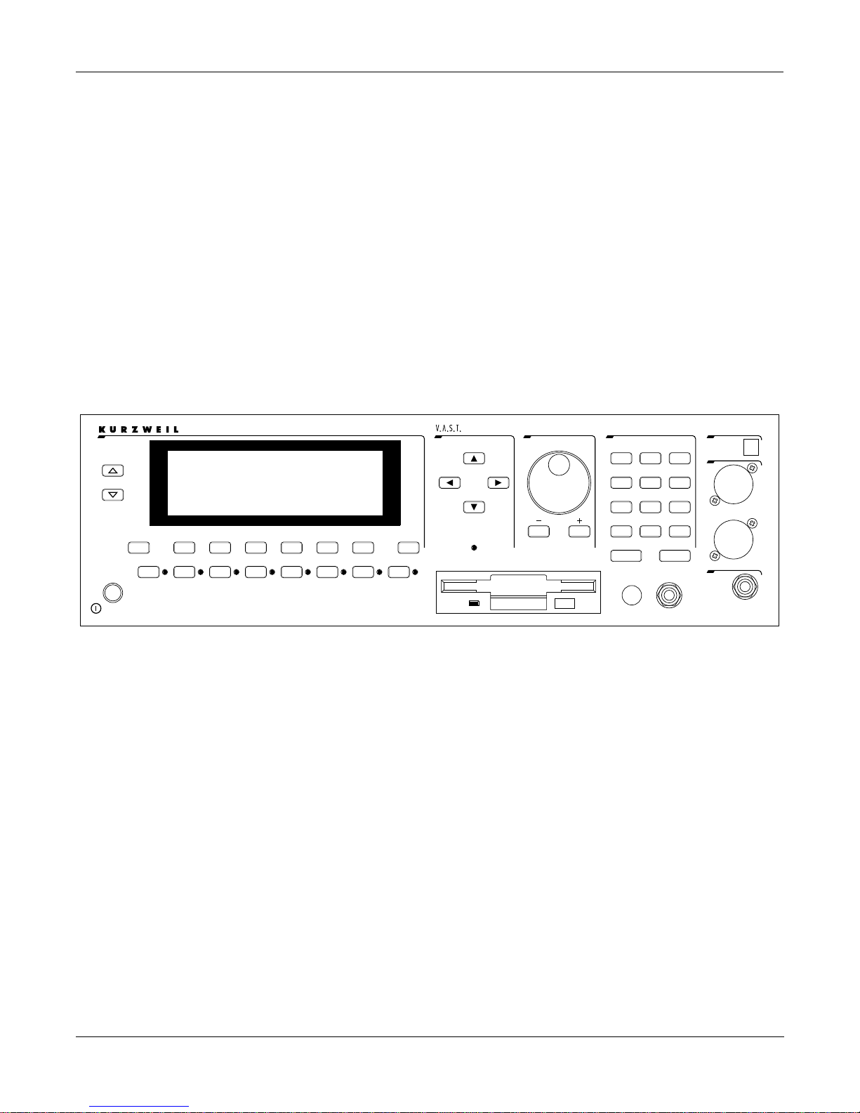
Front Panel Quick Reference
This section describes features common to both the rack versions of the K2500 (K2500R and
K2500RS) as well as the keyboard versions of the K2500 (K2500, K2500S, K2500X, and
K2500XS). The buttons and sliders that are unique to the keyboard models are described on
page 1-4.
C
han/Bank
Layer/Zone
P
ower
echnology
TSAV
2500RS
K
Sampler
dit
E
P
rogram
Mute 1
Zoom -
Access
etup
QS E MIDI
Mute 2
Mute 3
Zoom +
Samp/Sec
ffects
FX Bypass
Previous Pg
Gain -
M
Mark
Gain +
aster
S
Jump
Link
ong
isk
D
Compare
E
xit
MIDI
ynthesisrchitectureariable
ptical In
O
DEF
MNO
VWX
0-9
2
5
8
0
E
eadphone
H
CLR
Space
nter
GHI
PQR
3
oZ
L
6
9
YZ
H
Left
Right
iZ
Tip=Left
Ring=Right
1
ABC
4
JKL
7
STU
+
-
/
UPPER/lower
ancel
C
olume
V
Volume Knob/ Slider
Controls mixed audio outputs and headphone jack only. Does not send MIDI Volume (MIDI
07).
Mode Buttons
Press any of these eight buttons to enter the corresponding mode.
Chan/Bank Buttons
Scroll through the layers of the current program while in the Program Editor. Scroll through the
zones in the current setup while in Setup mode. Scroll through the Quick Access banks while in
Quick Access mode.
Edit Button
Functional in most modes. Press Edit to modify the currently selected object or parameter. If it’s
not editable, pressing Edit will do nothing.
There are editors available from every mode but Disk mode. The effect of pressing Edit in each
of the modes is listed below.
1-1
Page 8

Front Panel
Front Panel Quick Reference
When in this mode—Pressing the Edit button…
Program mode— …enters the Program Editor, where you can edit the currently se-
Setup mode— …enters the Setup Editor, where you can edit the currently selected
Quick Access mode— …enters the Quick Access Editor, where you can change the pro-
Effects mode— …enters the Effects Editor, where you can edit the currently selected
MIDI mode— …enters the Velocity Map or Pressure Map Editor if the Velocity or
Master mode— …enters the Velocity Map, Pressure Map, or Intonation Table Editor
Song mode— …enters the Song Editor. The Song Editor is discussed in Chapter 12
Disk mode— …has no effect.
lected program. Chapter 6 in the Performance Guide covers the Program Editor.
setup. Chapter 7 in the Performance Guide describes the Setup Editor.
gram or setup assigned to the bank slot that was selected when you
entered the Quick Access Editor. See Chapter 8 in the Performance
Guide .
effects preset. Chapter 9 in the Performance Guide explains the Effects
Editor.
Pressure Map parameter is selected on either the XMIT page or the
RECV page. See Chapter 17 in the Performance Guide . Enters the Program Editor if the Program parameter is selected on the CHANLS
page. See Chapter 6 in the Performance Guide .
if the VelTouch, PressTouch, or Intonation parameter is selected.
in the Performance Guide . Enters the Program Editor if the Program
parameter is highlighted when Edit is pressed.
Soft Buttons
Functions change depending on current display page. Function of each button is displayed on
bottom line of display.
EXIT Button
Press to leave various editors. If you’ve made any changes while in the editor, you will be
prompted to save them.
Cursor Buttons
Press the corresponding button to move the cursor up, down, left, or right in the display.
Different parameter values will be highlighted as buttons are pressed.
Alpha Wheel
For data entry. Rotate clockwise to increase value of currently selected parameter,
counterclockwise to decrease.
Plus / Minus Buttons (- and +)
Under the Alpha Wheel. Press to increase or decrease the value of the currently selected
parameter by the smallest possible amount.
1-2
Page 9

Alphanumeric Pad
For Numeric Characters
Enter the value numerically instead of using the Alpha Wheel or Plus/Minus buttons. Press
ENTER when finished. Press CANCEL to restore a parameter to its previous value. Pressing
CLEAR is equivalent to pressing 0 without pressing ENTER.
For Alphabetic Characters
When naming objects, you can use the alphanumeric pad to enter letters instead of numbers. If
you’re renaming a program, for example, just position the cursor under the character you want
to change, then press the corresponding numeric button, as labeled. Press the button as many
times as necessary to enter the desired character. Pressing CLEAR will enter a space before the
selected character. The “0” button will enter the numerals 0–9 when pressed repeatedly.
Here’s an example. To enter the letter “C” in a blank space, press “1” three times. You can press
the +/- button before or after entering the letter.
Front Panel
Front Panel Quick Reference
The CANCEL button is equivalent to the >>> soft button, and ENTER is the same as OK. The
CLEAR button replaces the currently selected character with a space. The “+/-” button toggles
between uppercase and lowercase letters.
When you press the +/- button on the alphanumeric pad, the currently selected character (the
one with the cursor under it) will switch from upper case to lower case, and vice versa. The +/button is a toggle; that is, if you switch from lower to upper case, all further entries will be in
upper case until you press the +/- button again.
There are several punctuation characters available as well, but they can be entered only with
the Alpha Wheel or Plus/Minus buttons. The punctuation characters are between “z” (lower
case) and “0.”
Special Alphanumeric Pad Functions
When you’re in Quick Access mode, the Alphanumeric pad can be used to select the entries in
the current Quick Access bank. The layout of the alphanumeric pad corresponds to the layout
of Quick Access bank entries as seen on the Quick Access mode page.
There’s also a shortcut for selecting different QA banks while in QA mode. Just press the +/- or
CLEAR button on the alphanumeric pad, and you’ll be prompted to enter a bank number. Type
the desired number on the alphanumeric pad, then press ENTER. The bank will be selected,
and you’ll return to the Quick Access page.
You can also use the alphanumeric pad to select strings to search for in the currently selected
list of objects, and to enter new strings to search for. The search function is described fully in
Chapter 3 in the Performance Guide .
echnology
TSAV
2500RS
K
Sampler
C
han/Bank
Layer/Zone
dit
E
P
rogram
ffects
Access
etup
QS E MIDI
Mute 1
FX Bypass
Mute 2
Mute 3
Zoom -
Zoom +
Samp/Sec
P
ower
ynthesisrchitectureariable
E
xit
MIDI
aster
M
ong
S
isk
D
Mark
Compare
Previous Pg
Jump
Gain +
Gain -
Link
Lastly, rack users can play notes from the numeric keypad by holding down the Cancel button
ptical In
O
3
1
2
oZ
L
ABC
DEF
GHI
5
6
4
JKL
MNO
PQR
Left
7
8
9
while pressing alphanumeric buttons. This, too, is described fully in Chapter 3 in the
STU
VWX
YZ
+
/
0
CLR
UPPER/lower
0-9
Space
ancel
C
nter
E
Right
iZ
H
Tip=Left
Performance Guide .
olume
V
eadphone
H
Ring=Right
The Display
You may want to adjust the contrast of the display for different lighting conditions. The
Contrast parameter in Master mode lets you set the contrast to your liking.
MIDI LED
Lights when the K2500 is receiving MIDI information at its MIDI In port.
1-3
Page 10
Front Panel
Special Keyboard Functions
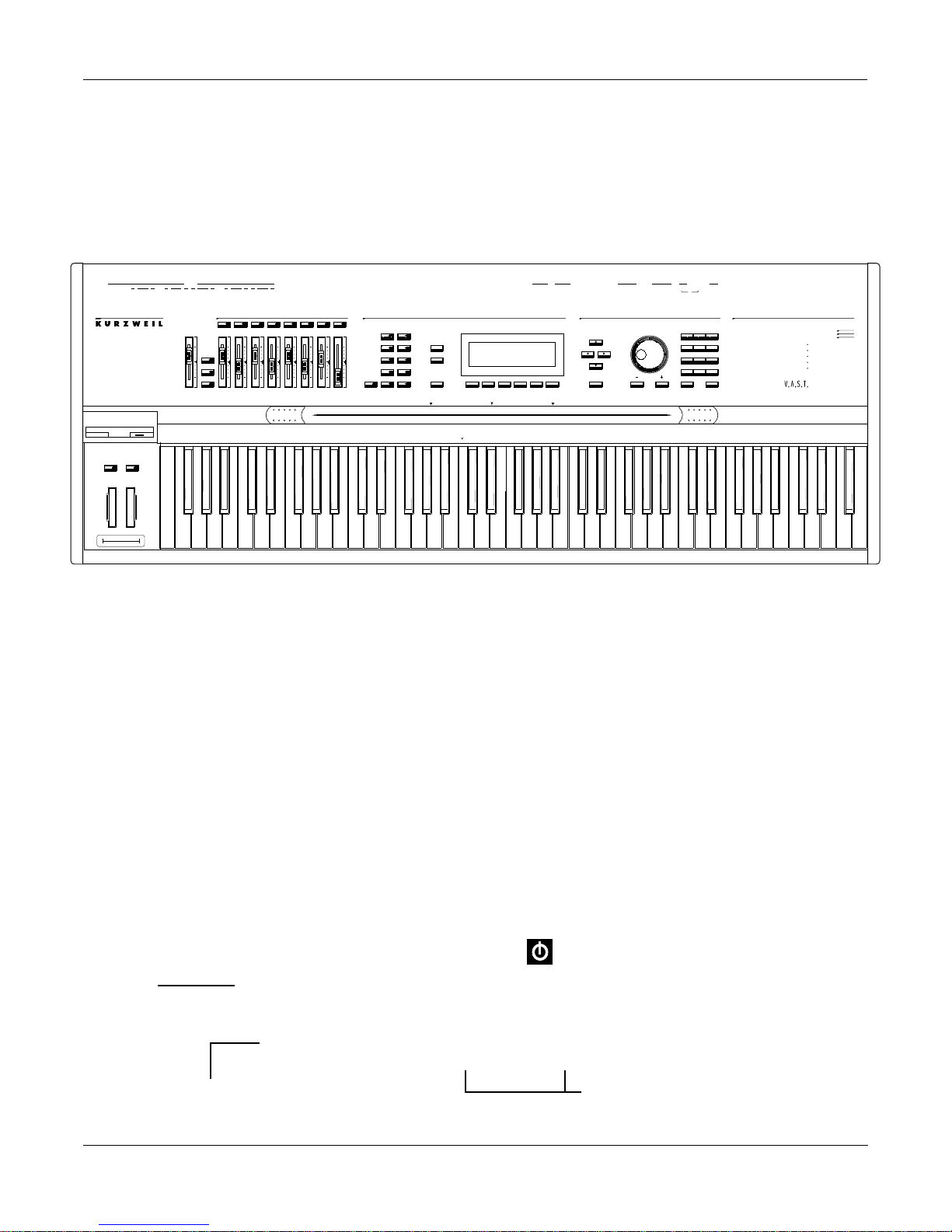
Special Keyboard Functions
This section describes the buttons and sliders that are unique to the keyboard models of the
K2500. Features common to both rack and keyboard models are described starting on page 1-1.
A
udio
uts
H
eadphones
SW1 SW2
ix
M
R
O
B
C
LDRL
R
aster Volume
M
olo
S
ixdown
M
Faders
MIDI
RL
ontrollers
ssignable
AC
132
A
A
LRL
D
igital OutOptical Out
4756 8
CB D
EF
O
ptical In
D
igital In
G
H
L
oZ Right In
L
oZ Left In
rogram
P MIDI
Zoom -
S
aster
M
etup
Mute 2
Zoom +
Q
ong
S
Access
Mute 3
Samp/Sec
ffects
E
isk
D
FX Bypass
lay/Pause
S
R
ecord
top
P
S
MIDI
Select
MIDI
iZ In
H
Previous PgMute 1
Gain -
Mark
Gain +
C
han/Bank
Jump
Link
Layer/Zone
Compare
E
dit
4
C
OutOut Thru
SCSI
InOut/Thru
SCSI
ntry
D
E
ata
witch Pedals
4
Thru
xit
E
Pedals / Breath
CC
213
or
1 32
ABC
4
JKL
7
STU
+/-
UPPER/lower
ancel
C
2Breath
DEF
MNO
8
VWX YZ
0
0 - 9
KDS
Output
1
GHI
695
PQR
C
lear
Space
E
nter
P
ower
K
2500
orty-Eight Voices
F
D
igital Multi Effects
ulti-Track Sequencer
M
xpandable to 28MB of Sound ROM
E
E
xpandable to 128MB of Sample RAM
ynthesisrchitectureariable
echnology
TSAV
Shows whether
physical sliders
control pan or
volume.
Solo button
Mutes all zones in Setup except the current one. The button of the zone being soloed glows red.
Mixdown button
Brings up the Mixdown screen, as shown below. From this screen you can choose how the
K2500’s physical sliders will function during MIDI mixdown. In the example below, the
physical sliders A-H will control the volume level of MIDI channels 1-8. By pressing the Pan
soft button, you would change the function of the physical sliders to control panning for
channels 1-8; or, you could press the 9-16 soft button to have the physical sliders affect channels
9-16.
You can also use the cursor buttons to highlight the pan or volume control for a channel and
use the alpha wheel or increment/decrement buttons to change the pan or volume level. In the
screen below, for example, you could use the alpha wheel to control panning on channel 9 at
the same time that you are using the physical sliders to control volume on channels 1-8.
Mixdown||||<>Prog:|36|DuckWalk||||||||||
|||WXWXWXWX|WXWXWXWX|WXWXWXWX|WXWXWXWX||
|||wxwxC{wx|wxwxwxwx|wxwxwxwx|wxwxwxwx||
>>||z|z}~|z||z|z|z|z||z|z|z|z||z|z|z|z||
||||_|_|_|_||_|_|_|_||_|_|_|_||_|_|_|_||
||||||||||||||||||||||||||||||||||||||||
|||*****************||||||||||||||||||||
|Pan|||Volume|Ch|1-8|Ch9-16|||||||||Done
Shows which channels are affected
by physical sliders.
1-4
Soft buttons for indicating
which channels are affected
by physical sliders.
Page 11

Front Panel
Special Keyboard Functions
MIDI Faders button
When you press the MIDI Faders button, the K2500’s physical sliders will take on the functions
assigned on the current MIDI Faders page. From the MIDI Faders display you can define four
different "pages" that define how the K2500’s physical sliders will work. In the display shown
below, for example, the eight sliders are each defined to send controller 6 (data) on the channels
9 through 16. Press one of the page soft buttons to use (or create) a different page of MIDI fader
assignments. Use the Send soft button to transmit values without moving the faders.
The MIDI Faders pages will be saved with the Master table object.
MIDI|Faders:Page2|||||||||||||||||||||||
Chan|:|9|||10||11||12|||13|||14||15||16|
Ctl||:|6|||6|||6|||6||||6||||6|||6|||6||
Value:|0|||0|||0|||0||||0||||0|||0|||0||
||||||||||||||||||||||||||||||||||||||||
||||||\]||}~||\]||}~||||\]||}~||\]||}~||
|||||||_|||_|||_|||_|||||_|||_|||_|||_||
Page1||Page2||Page3||Page4|||Send|||Done
Assignable Controllers (buttons 1-8 and sliders A-H)
The function of these controllers will depend on how they’ve been defined within a setup.
SW1, SW2
The function of these controllers will depend on how they’ve been defined within a setup.
Record, Play/Pause, Stop
These buttons duplicate their namesake soft buttons in Song mode, allowing you to
conveniently record, play, pause, and stop the current song.
1-5
Page 12

Front Panel
Special Button Functions
Special Button Functions
The mode buttons, as well as few of the other buttons, have additional functions, as described below. When
you’re in the Program or Setup Editor, they have special functions, as indicated by the green labeling under
each button, and they also work as track mutes on the Mixer page of Song Mode.
Program
Setup
Q Access
Effects
MIDI
Master
Disk
Chan/Bank
/ Mute 1 When you’re in the Program Editor, this button will mute Layer 1 of the current
program or the currently displayed layer for drum programs. While in the Setup Editor,
it will mute Zone 1 of the current setup, if the setup has three or fewer zones; mutes
current zone in setups with more than three zones. On MIXER page of Song mode,
mutes either track 1 or 9.
/ Mute 2 When you’re in the Program Editor, this button will mute Layer 2 of the current
program, if any. For drum programs, solos currently displayed layer. While in the Setup
Editor, it will mute Zone 2 of the current setup, if the setup has three or fewer zones;
solos current zone in setups with more than three zones. On MIXER page of Song mode,
mutes either track 2 or 10.
/ Mute 3 When you’re in the Program Editor, this button will mute Layer 3 of the current
program, if any. For drum programs, solos currently displayed layer. While in the Setup
Editor, it will mute Zone 3 of the current setup, if the setup has three or fewer zones;
solos current zone in setups with more than three zones. On MIXER page of Song mode,
mutes either track 3 or 11.
/ FX Bypass When you’re in the Program Editor, pressing this button will bypass (mute) the preset
effect assigned to the current program, letting you hear just the sound of the layer(s)
you want to hear. On MIXER page of Song mode, mutes either track 4 or 12.
/ Prev pg In the Program Editor, pressing this button will take you to the previously selected
editing page. The K2500 remembers the four most recently selected pages, so you can
press this button up to four times to backtrack through the pages you’ve viewed.
Pressing it a fifth time will take you back to the ALG page. On MIXER page of Song
mode, mutes either track 5 or 13.
/ Mark This is handy for marking Program Editor pages that you use frequently. Pressing this
button will mark the currently selected page. You can mark as many pages as you like.
Then you can use the Jump button to select the marked pages in the order you marked
them. Marked pages will show an asterisk in the top line of the display, just before the
name of the page. A marked page can be unmarked by pressing the Mark button while
the page is visible. On MIXER page of Song mode, mutes either track 6 or 14.
Song
/ Jump Use this button to jump to pages in the Program Editor that you’ve marked with the
Mark button. This will cycle through all the currently marked pages in the order they
were marked. On MIXER page of Song mode, mutes either track 7 or 15.
/ Compare This button works in most editors, and lets you compare your edits with the original
version of the object you’re editing. When you press the Compare button, the display
changes to remind you that you’re listening to the original version. Press any button to
return to the currently selected page of whatever editor you’re in. On MIXER page of
Song mode, mutes either track 8 or 16.
/ Layer/Zone In the Program Editor, these buttons let you scroll through the layers in the currently
selected program. In the Setup Editor, you can scroll through the zones. In the Effects
Editor, you can scroll through the effect configurations. In the Quick Access Editor, they
scroll through the entries in the currently selected Quick Access bank. In the Keymap
Editor, they scroll through the velocity levels of multi-velocity keymaps. In Song mode,
switches record track.
Edit
Whenever the selected parameter’s value is an editable object or a programmable
parameter, pressing the EDIT button will take you to that object’s editor, or to the
parameter’s programming page.
1-6
Page 13

Front Panel
Special Button Functions: Double Button Presses
Special Button Functions: Double Button Presses
Pressing two or more related buttons simultaneously executes a number of special functions depending on
the currently selected mode. Make sure to press them at exactly the same time.
In This Mode: These Buttons: Will Do This:
(Pressed simultaneously)
PROGRAM MODE Octav-, Octav+ Reset MIDI transposition to 0 semitones. Double-
press again to go to previous transposition.
Chan-, Chan+ Set current MIDI channel to 1.
Plus/Minus Step to next Program bank (100, 200, etc.)
MASTER MODE CHAN/BANK Enables Guitar/Wind Controller Mode.
SONG MODE left/right cursor buttons Toggle between Play and Stop.
up/down cursor buttons Toggle between Play and Pause.
Plus/Minus Select Quantize Grid values on MISC page and
Edit Song:TRACK Quantize page. Select duration
for a step on Edit Song:STEP page. Increment GateTime by 20% intervals on Edit Song: STEP page.
CHAN/BANK Select all tracks on any Edit Song:TRACK page.
DISK MODE 2 leftmost soft buttons Issue SCSI Eject command to currently selected
SCSI device.
CHAN/BANK Hard format SCSI device. List selected objects
when saving objects.
left/right cursor buttons Select all items in a list. Move cursor to end of
name in naming dialog.
up/down cursor buttons Clear all selections in a list. Move cursor to begin-
ning of name in naming dialog.
PROGRAM EDITOR CHAN/BANK Select Layer 1.
KEYMAP EDITOR Plus/Minus With cursor on the Coarse Tune parameter, tog-
gles between default Coarse Tune of sample root
and transposition of sample root.
SAMPLE EDITOR 2 leftmost soft buttons Toggle between default zoom setting and current
zoom setting.
1-7
Plus/Minus Set the value of the currently selected parameter
at the next zero crossing.
Page 14

Front Panel
Special Button Functions: Double Button Presses
Special Button Functions: Double Button Presses
In This Mode: These Buttons: Will Do This:
(Pressed simultaneously)
ANY EDITOR Plus/Minus Scroll through the currently selected parameter’s
2 leftmost soft buttons Reset MIDI transposition to 0 semitones. Double-
Center soft buttons Select Utilities menu (MIDIScope, Stealer, etc.).
2 rightmost soft buttons Sends all notes/controllers off message on all 16
left/right cursor buttons Toggle between Play and Stop of current song.
list of values in regular or logical increments (varies with each parameter).
press again to go to previous transposition.
channels (same as Panic soft button).
up/down cursor buttons Toggle between Play and Pause of current song.
SAVE DIALOG Plus/Minus Toggle between next free ID and original ID.
1-8
Page 15

1
7
12
15
Programs, Setups, and Keymaps
K2500 Program List
Chapter 2
Programs, Setups, and Keymaps
K2500 Program List
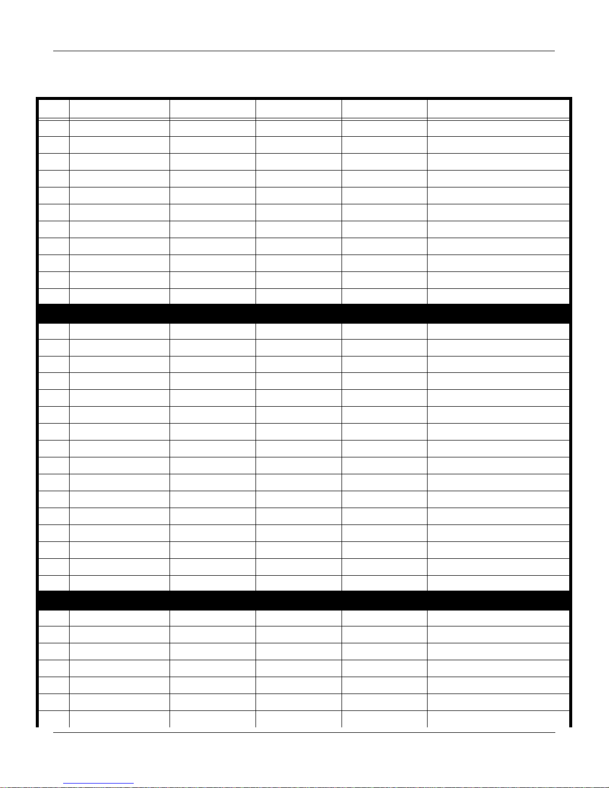
The 200 preset programs in the K2500 are organized by instrument category. You will find a few representatives of
each instrument sampled for the base ROM soundset, as well as synthesized instrument emulations, commonly
used synthesizer timbres, and templates for new programming. We hope you find it a good starting point for your
own work.
There are many ways to put expressivity and variety in a single program by assigning MIDI controllers to the
various DSP functions in its layers. This list describes how each of the 200 factory preset programs can be
modulated or altered by the various MIDI controls. Only those controls which may not be immediately evident are
listed. Controls such as attack velocity and keynumber are understood to be assigned to most programs.
Prg # Program Name Mod Wheel Data MPress Comments
KEYBOARDS
Acoustic Piano
2 Stage Piano
3 BriteGrand
4 ClassicPiano&Vox
5 Ballad Pno&Str
6 Rock Piano 1
Honky-Tonk
8 E Grand & Pad
9 Classic E Piano
10 Dyno E Piano
11 E Piano PF
Suitcase E Pno
13 Brite Klav
14 Match Stick
-
COMPING SYNTHS
Big PWM
16 Matrix 12
17 OBX Braz 4
18 Memorymoog 4
19 Prophet Pulse 2
20 Prophet Square 2
Choir Balance
Strings Balance Soft Ped.
Tremolo
Pad Balance
Tremolo
Vibrato Depth Vibrato Rate
Layer Balance 8vb
Vibrato Vibrato, W/D Mix
Vibrato Filter & Env Ctl Vibrato
Vibrato Filter & Env Ctl Vibrato
Vibrato Filter & Env Ctl Vibrato
Vibrato Filter & Env Ctl Vibrato
Vibrato Filter & Env Ctl Vibrato
Vibrato Filter & Env Ctl Vibrato
Soft Ped.
Soft Ped.
Soft Ped.
Soft Ped.
Soft Ped.
2-1
Page 16
21
32
48
Programs, Setups, and Keymaps
K2500 Program List
Prg # Program Name Mod Wheel Data MPress Comments
New Shaper
22 Klicomp tree
23 Digicomp
24 Da Clav
25 Simpilton
26 Synth Caliope
27 Chiffloots
28 Bamboo Voices
29 Hyper Guitar
30 Dreamers
31 Pluxichord
LEAD SYNTHS
Fluty Lead
33 Gooshy Lead
34 Orient Wind
35 DC Lead
36 Duke's lead
37 FM Harmonica
38 Mini Lead Poly
39 AlaZawi
40 JR's Lead
41 Funky Lead
42 Hammeron Synth
43 Synthitar Lead
44 Modular Lead
45 Prophet Sync
46 Brt Saxy Lead
47 Don Corllione'
DRUMS
Studio Kit 1
49 Studio Kit 2 MW
50 2 Live Kits MW
51 Rock Kit
52 Jazz Kit
53 Reggae Kit
54 Light Kit
Vibrato Env Ctl Vibrato
Vibrato, Filter Env Detune, Env Ctl Vibrato, Filter Env
Vibrato Env Ctl Vibrato
Env Ctl
Vibrato Env Ctl Vibrato, Filter Ctl
Vibrato Env Ctl
Vibrato Chiff Pitch Vibrato
Vibrato Alt Atk Vibrato
Dly Vib Dly Vib
Tremolo Tremolo
Env Ctl
Vibrato Vibrato
Distance W/D Mix
Vibrato W/D Mix Vibrato, Filter Ctl
Vibrato Timbre Ctl Vibrato
Vibrato W/D Mix, Filter Vibrato
Vibrato Tremolo
Vibrato Pitch Vibrato
Timbre Ctl Filter, Resonance Vibrato
Vibrato Timbre Ctl Feedback
Vibrato W/D Mix Vibrato
Filter 1 Filter 2
Vibrato W/D Mix Vibrato
Vibrato 8 ve’s Vibrato
Vibrato Slave Osc Pitch
Vibrato W/D Mix Vibrato
Vibrato Vibrato
W/D Mix
Alt Atk W/D Mix
Alt Kit W/D Mix
Alt Toms W/D Mix
Alt Atk W/D Mix
W/D Mix
W/D Mix
Att Vel controls Hi Hat’s decay
Att Vel controls Hi Hat’s decay
2-2
Page 17

55
63
71
Programs, Setups, and Keymaps
K2500 Program List
Prg # Program Name Mod Wheel Data MPress Comments
84
Garage Kit MW
56 Techno Kit
57 General MIDI Kit
58 Slam'n Drums
Alt Kit W/D Mix
Alt Kick W/D Mix(Flange)
W/D Mix
W/D Mix(Flange)
59 Perc Section MW Add Cowbell, Shaker W/D Mix
60 Industry Set
61 Techno Loops
62 Rhythmatic
Resonance (A#4-C5) Resonance (A#4-C5)
Loop Tempo Loop Tempo
Disable Multilay-erRhythm Tempo
PERCUSSION
Dualimba
64 TouchDrums
65
Hand Drums
Vibrato Amp Vibrato
Vibrato Amp Vibrato, Pitch
W/D Mix,
Pitch Envelope
66 Dynamic Perc
67 Mark Tree
68 Bell Player
69 Marimba
70 Excited Marimba
Heartbeat (C2)
Filter
W/D Mix,
Heartrate (C2)
W/D Mix, Env Ctl
Vibrato Vibrato
EQ Amp
Alt Atk
BASSES
Dual E Bass
72 Warm Bass
73 Sustain E Bass
74 Ripper Bass
75 Yama Bass
76 Synth Fretless
77 Fretless Lead
78 Moogy Bass 1
79 Moogy Bass 2
Vibrato Vibrato
Vibrato Vibrato
Vibrato Vibrato
Vibrato Vibrato
Layer Balance
Vibrato Vibrato
Vibrato Vibrato
Vibrato Filter Vibrato
Filter Depth Resonance Depth Vibrato
Att Vel controls Hi Hat’s decay
Mod Wheel Engages Non-
tracking Congas
80 Mix Bass
81 Tite Rave Bass
82 Synth Bass
83 House Bass
Filter Depth Layer balance
W/D Mix Filter, Depth
Filter Ctl
Vibrato Filter Vibrato
GUITARS
Acoustic Guitar
85 Steel Str Guitar
Vibrato EQ Vibrato
SoftPd
2-3
Page 18
Programs, Setups, and Keymaps
K2500 Program List
Prg # Program Name Mod Wheel Data MPress Comments
86
12-str Guitar
87 Strummer Guitar
88 Slo Chorus Gtr
89 Captain Crunch
90 Smooth Lead
Vibrato EQ Vibrato
Tremolo EQ
Vibrato Filter , W/D Mix Vibrato
Shaper, W/D Mix Feedback
EQ SoftPd
PBend goes +2 and -12ST
91 Dist Harmonics Tremolo W/D Mix
92 Kotolin EQ Vibrato
93 Cee Tuar Vibrato Alt Sound Vibrato
94 Green Acres
ORGANS
95 Perc Organ 2500 Rotary Speaker
Perc Balance
96 Ballad Organ 2 Rotary Speaker
97 Gospel Organ Rotary Speaker Perc Balance
98 Drive Organ Rotary Speaker Distortion Ctl
99 Rotating B's & M's Rotary Speaker
100 Cheeze Vibrato Depth Env Ctl Vibrato Depth
101 Tamborgan Vibrato Perc Pitch Vibrato
102 Organ Pad Tremolo
103 Chiffy Pipes
104 Offertory
Decrescendo
Layer Balance
105 Pedal Pipes Decrescendo
106 Church Organ Vibrato Layer Balance Vibrato
Velocity Sensitive
107 Resorgan Dynamics Sost Pdl Does Release Ctl
STRINGS/CHOIR
108 Fast Strings
109 Att ctl Fast Str
Filter
Filter For Fast Solo Lines& Active
Comping
110 Att ctl Med Str Env Ctl
For Med or Slow (MW) Solo
Lines
111 SfzTrem Strings
Sfz Envelope Triggered by In-
creased Att Vel
112 ClassicalStrings Vibrato Depth
113 SloClassical Str Decrescendo
114 Silk Strings Decrescendo W/D Mix Vibrato Depth
For Light, Active Comping
For Chordal Comping
For Chordal Comping
115 Fast Violin Vibrato Depth
116 Slo Solo Cello Quick Fade W/D Mix Vibrato Depth
117 Stereo Slo Str
Filter
Velocity Controls Timbre Shift
2-4
Page 19
Programs, Setups, and Keymaps
K2500 Program List
Prg # Program Name Mod Wheel Data MPress Comments
118 Cathedral Choir
Decrescendo
Att Ctl Allows Smooth Voice
Leading in 4-Part Playing
119 Mixed Choir Layer Balance
120 The Choir Vibrato Release Env Vibrato
WINDS
121 Wendy's Flute
Higher Att Vel = Less Tremolo
122 Treble Flute
123 Baroque Flute
124 Soft Tenor Sax W/D Mix Vibrato, Filter
125 Fast Solo Tenor EQ Vibrato
For Fast Legato Lines
BRASS
126 Dynamic Trumpet Swell W/D Mix Vibrato
127 Miles Unmuted Vibrato Timbre Ctl Vibrato
128 Strght Mute Trpt Vibrato Defeat W/D Mix Vibrato Rate
129 Almost Muted Vibrato, Amp Timbre Ctl Vibrato
130 Solo Trombone W/D Mix Vibrato Depth
131 Sfz Bone
ENSEMBLES
132 Trumpet Section Swell
133 Hip Brass Vibrato W/D Mix Swell
134 Brt Miami Brass Bright Swell
135 Orchestral Brass Swell
136 Sax Section Swell W/D Mix Swell
137 Dyn Big Band Softer Swell
Sfz Envelope
Sfz Envelope
138 Flute & Slo Str Solo String Swell Vibrato Depth SostPd disables Solo Str. Release
Velocity Controls Strings Release
139 Horn&Flute w/ Str Strings Balance Rel. Velocity Controls Strings
Rel.
140 DynamicOrchestra
Light playing engages a horn, flute & string ensemble.
SostPed holds a chord and engages an ensemble suited to solo lines.
At forte, bigger brass is enabled, with pressure controlling a swell.
141 Touch Orchestra
Mod wheel replaces RH trumpets with solo flute.
Each Velocity level brings in a new instrument:
At forte, horns are doubled; at double forte, kettle drums play; at fff, crash cymbal plays.
142 Slo Ensemble Synstring Res Synstring Filter Vibrato Depth
2-5
Page 20

Programs, Setups, and Keymaps
K2500 Program List
Prg # Program Name Mod Wheel Data MPress Comments
143 W Tell Orchestra
Swell Swell
For Active Marcato Comping
SostPD Latches and Disables
Brass
144 Jazz Band
LH Bass layered with ride for walking rhythm section.
Data slider switches from guitar to horn section;
SostPed holds brass and adds solo Tenor. Throw the ModWhl for drum solo.
145 Rock Quartet
LH Bass layered with hihat for driving rhythm section.
At forte, kick, snare, and rhythm guitar are added.
Mod wheel does rotary speakers for the organ.
HYBRID SYNTHS
146 Gargantuanism Vibrato Layer Balance Vibrato SostPd Disables Strings
147 Tranquil Pluck
Vibrato
Release Ctl Vibrato
148 The Chase Vibrato W/D Mix Vibrato
149 Enterprize Tremolo Bell Pitch Tremolo
150 Magic Orchestra Piano Balance SostPd Disables Cymbal
151 Passion Source Detune Detune, Swell
152 Microwave Vibrato Release Ctl Vibrato
153 Fuzz Lite Vibrato Release Ctl Vibrato
154 Solina Phaze Vibrato Phaser Rate Vibrato
155 Arystal Layer Balance
156 Timershift Vibrato Release Ctl Vibrato
157 Aurora Mod Speed W/D Mix
158 Gongers Vibrato Pitch, W/D Mix Vibrato
159 Arrakis Grand Vibrato Depth Detune Vibrato Depth
160 Sisternal
Vibrato
Release Ctl
Vibrato
161 PPG 4 Vibrato W/D mix, Env Ctl Vibrato
162 Pseudomento MW
Pseudomento
Rate
163 Big Strings Vibrato Vibrato
164 Spaced Dly Sweep Mod Rate
165 Digital Choir Res Mod Filter Ctl
166 Meditation Pad Res Mod Filter Ctl Vibrato Move data slider from top to
bottom and throw the MW for
best resonance effect.
167 The Cymbal Sings Vibrato Filter
168 Slo FlangeStrngs Flange Rate
Template: Using allpass to cre-
ate flanging within a layer
2-6
Page 21
Programs, Setups, and Keymaps
K2500 Program List
Prg # Program Name Mod Wheel Data MPress Comments
169 Lushlife
170 Crystal too Vibrato Sine Wave Pitch Vibrato
171 Multi Marimba Vibrato Delay Time Vibrato
172 Wave Power Vibrato Vibrato
173 Noo Mutes Pitch Effect Filter Ctl, W/D Mix
174 Hammer Violin Pitch Effect Env Ctl, W/D Mix Vibrato
175 Mallet Flutes
Chiff Pitch
W/D Mix
176 Malletoo Pitch Mod Depth Pitch Mod Rate
177 Ethereal Echoes
Disable Bell
PAD SYNTHS
178 Padifier Vibrato Filter Vibrato
179 Spaced Inn Vibrato Vibrato
180 Glass Bow Vibrato Env Ctl Vibrato
181 Angel Pass
182 In the Air Vibrato Filter Ctl Vibrato
183 Matrix Mellostr Vibrato Env Ctl Vibrato
184 Ethereal Strings Filter Sweep Filter
185 Dawning Sweep Fade
186 Synth Strings
187 Choir Fixer Vibrato, Pan W/D Mix Vibrato
188 Shine On Vibrato Filter Ctl Vibrato
189 ChoirStrings
190 Launch Pad Timbre Ctl Timbre Ctl
EFFECTS SOUNDS
191 cymbal thing
192 a no way CS Mod Depth Mod Rate
193 Environments
194 Gremlin Group Timbre Ctl,
Env Ctl
195 Thunder Storm
Vibrato>Pitch,
Resonance
Play Sparse Staccato Notes in
LH for Thunder. RH is Rain
196 Northern Winds Pan Rate, Filter
197 Doomsday Pitch
UTILITY
198 Click Assigned to output group B (dry)
199 Default Program Used in New Lyr, Sample au-
2-7
dition, and Preview Program
Page 22

Programs, Setups, and Keymaps
Setup List
Setup List
The Performance Setup, or "Setup" is a combination of up to eight zones, each with
independent MIDI channel and controller transmission assignments. Setups can be played on a
K2500R via the Local Keyboard Channel feature: Find this parameter in MIDI mode on the
RECV page, change it from None to a channel of your choice, and set your controller to send on
only that channel. Now, any note that comes in on that channel will be re-mapped according to
the display channel (in program mode) and according to the Setup (in Setup mode).
Below is a list of the Setups provided with V2 software; there are detailed descriptions on the
pages that follow.
ID# NAME ID# NAME ID# NAME
1 Sahara Touch 35 F1 Perc Comper 69 Digi Ensemble
2 Ethereal Split 36 Multi Chords 70 Pluck Stack
3 Slo Orchestra 37 3-Sec Talk sldrs 71 Quillmeister
4 Whirligig 38 FM Slider Play 72 Organ Select
5 Modern Harpsichord 39 E Grnd Pad 73 Perc Stack 2
6 Kogs & Things 40 BalladCompSplit 74 Action Scene
7 Desert Soil 41 Maggie May 75 Rusty Teeth
8 Mellow BigBand 42 EPnoPad rbnvel 76 Split Stack
9 Fusion Split 43 Dukes Up 77 Pulse Brass
10 Touch Rock Band 44 F1 Latin Comper 78 Majesty
11 Plucksynths 45 Floyd’s Echo 79 Classy Orch
12 Big Pad RbnVel 46 Poly Portem 80 Motion Pad
13 Cembellophone 47 C2 and Lead 81 Wiry Comp 3-Sec
14 MidEast Drone 48 PowerLead 82 GrimlyFiendish
15 Ribbon Thunder 49 Big Synbrass 83 Hold & Tap
16 Press Roll Orch 50 WahPedZawiSplit 84 LayeredSnare Kit
17 C7 F7 G7 Groove 51 Clav EP Organ 85 C#2 Jam
18 Folk Comper 52 Toxic Cheese 86 PassionPad
19 Extra Perc Drums 53 Floyd Wheel 87 Fusioner
20 Chiffer Lead 54 Under Water 88 Duo
21 Slider Play 1 55 Lullaby 89 A2 Foot Drummer
22 Mist Strings 56 Alazawilude 90 Aqua Choir
23 New Pulsar 57 Three Leads 91 Massy Orch
24 It’s Coming 58 News Room 92 Mechanical Mike
25 Summer Snows 59 Aqua Ribbon 93 Haunted House
26 OrchScape 60 New Age Organ 94 All Alone 3
27 Threeway Xfade 61 Drum Arps 95 Witchcraft
28 Royal Dyn Brass 62 Perc Stack 96 Fallout
29 Fairlite Stack 63 3-Sec E Pno 97 Control Setup
30 Mr. Wiz 64 Touch Stick 98 Clear Setup
31 New Dawn 65 Ballad Comp 99 Default Setup
32 Sudden Horrors 66 Dual Synth
33 Cisco Kid 67 C2 Jam
34 ToyBuphone 68 Hertz
2-8
Page 23

Programs, Setups, and Keymaps
Version 2 Setups with Controller Assignments
Version 2 Setups with Controller Assignments
To take advantage of Version 2's eight zone setup capability, there are 100 new setups in the Version 2 Factory Objects. You will find unique internal program combinations, arpeggiator examples, special ribbon and controller
functions, and templates for user created setups. With as many as 24 assignable controllers shared among 8 independent zones, K2500 MIDI setups can be quite powerful, and they require some experimentation to find all their
features and nuances. In order to make this process easier, many setups are programmed according to the certain
conventions. The sliders generally provide mixing capabilities either as group faders or individual zone faders.
They also provide control over timbre, effects mix, and clock tempo. Other conventions include:
Slider F: Arp Vel
Slider G: Wet/Dry mix
Slider H: Tempo
PSw 1: Arp Switch
PSw 2: Latch2
Footswitch 1: Sustain
Footswitch 2: Sostenuto
Footswitch 3: Soft Pedal
Large Ribbon: Aux Bend 1
Small Ribbon Press: Mono Pressure
Small Ribbon Pos: Aux Bend 2
Mod Wheel: Mod Wheel
MPress: MPress
MIDI notes can be triggered from many controllers including pedals, switches, sliders and the ribbons.
Special Purpose Setups
There are three special setups at the end of the bank:
97 Control Setup lets you define controller assignments in program mode. You can customize and select the Con-
trol Setup on the MIDI Xmit page.
98 Clear Setup is a template for creating your own control assignments from a clear palette.
99 Default Setup lets you create your own setups from our common settings. The NewZn parameter uses this
setup as its template for creating new zones.
The complete list of controller assignments for the setups in Version 2 is on the following pages.
2-9
Page 24

Programs, Setups, and Keymaps
Version 2 Setups with Controller Assignments
1 Sahara Touch Sliders: A timbre, B-E zone faders; PSw: 1 arp sw, 2 mute group
2 Ethereal Split Sliders: A port time for bass, B-E zone faders; PSw: 2 port sw for bass; FootSw: 1 sost
& enables fretless bass, 2 enables drums
3 Slo Orchestra Sliders: A-E zone faders; L Rib: cymbal roll; Press: cym roll vel
4 Whirligig Sliders: A-F zone faders; L Rib: 1 aux bend, 2 pan, 3 pan
5 ModernHarpsichord Sliders: A-E zone faders
6 Kogs & Things Sliders: A-E zone faders; PSw 2: group mute
7 Desert Soil Sliders: A-C group faders, D timbre control, E detune; L Rib: pan
8 Mellow BigBand Sliders: A-C zone faders
9 Fusion Split Sliders: A-D zone faders
10 Touch Rock Band Sliders: A-E group faders, F snare balance; PSw 2: group mute
11 Plucksynths Sliders: A-F zone faders; L Rib: filter freq; PSw 2: group mute
12 Big Pad RbnVel Sliders: A-C zone faders; L Rib: filter freq, pan, arp vel, & fx depth; PSw 2: group mute
13 Cembellophone Sliders: A-E zone faders; L Rib: group mutes
14 Mideast Drone Sliders: A-F group faders; L Rib: tempo
15 Ribbon Thunder Sliders: A-C zone faders, D filter freq, H key vel for thunder; L Rib: thunder; ModWh
timbral modulation
16 Press Roll Orch Sliders: A-B zone faders; L Rib & MPress: arp vel for drum roll on keys G1 to F#2;
PSw2: mute group
17 C7 F7 G7 Groove Sliders: A-F group faders; FootSw: 1 crash cym, 2 ride cym; L Rib: pitch bend for bass;
PSw: 1 arp latch, 2 panic
18 Folk Comper Sliders: A zone fader, B group fader, C guitar timbre; PSw: 1 arp sw & zone mute, 2
latch2; L Rib: arp pan
19 Extra Perc Drums Sliders: A-B group faders; Mod Wh: drum timbre
20 Chiffer Lead Sliders: A-B group faders
21 Slider Play 1 Sliders: B velocity, C pitch bend, D pan, E expression; Slider A & L Rib: key num; PSw2:
panic; FootSw2: latch2
22 Mist Strings Sliders: A-C zone faders, D timbre, E pan
23 New Pulsar Sliders: A-B group faders; PSw: 1 arp latch, 2 group mute
24 It's Coming Sliders: A-D zone faders; FootSw1: arp latch
25 SummerSnows Sliders: A-B group faders, C timbre; FootSw1: arp latch; L Rib: arp vel and pitch bend
for bass
26 OrchScape PSw: 1 group mute, 2 group mute
27 Threeway XFade Slider A & L Rib: three way crossfade; Mod Wh: strings balance
28 Royal Dyn Brass Sliders: A-B group faders, C release time
29 Fairlite Stack Sliders: A-C group faders, D filter sweep, E key num, F key vel; PSw2: panic
30 Mr. Wiz Sliders: A-B group faders; FootSw2: latch2; Mod Wh & L Rib: filter sweep
31 New Dawn Sliders: A pad fade, B balance for pad and timbral modulation; L Rib: pad pan and
pitch bend
32 Sudden Horrors Sliders: A-C zone faders; L Rib: pitch bend and pan
33 Cisco Kid Sliders: A-C group faders, PSw2: group mute; FootSw1: arp latch; L Rib: pan
34 ToyBuphone Sliders: A-D zone faders
35 F1 Perc Comper Sliders: A-B group faders; PSw1: arp latch
2-10
Page 25

Programs, Setups, and Keymaps
Version 2 Setups with Controller Assignments
36 Multi Chords Sliders: A-B group faders; L Rib: filter sweep
37 3-Sec Talk Sldrs Sliders: A key num, B key vel; FootSw3: arp latch; PSw2: panic; L Rib Sect1 & Slider F:
pitch bend; L Rib Sect2 & Slider C: timbre; L Rib Sect3 & Slider D: filter modulation
speed
38 FM Slider Play Sliders: B key vel, C pitch bend, D timbre, F expression; L Rib and Slider A: key num;
PSw2: panic
39 E Grand Pad Sliders: A-B group faders, C Pad balance; Higher velocity enables zones 3 and 4
40 BalladCompSplit Sliders: A-B group faders, C release env & balance; L Rib: 1 bass pitch bend, 2 timbre,
3 bass timbre; FootSw3: mute zone 1
41 Maggie May Sliders: A-C mute groups, D attack time; PSw2: mute group
42 EPno Pad RbnVel Sliders: A-C zone faders; L Rib: arp vel, pan, fx depth, timbre; PSw1: arp sw & group
mute
43 Duke's Up Sliders: A-B zone faders, C pan; L Rib: arp vel
44 F1 Latin Comper Sliders: A-C group faders, D timbre; FootSw2: group mute; L Rib: bass pitch bend;
ModWh: extra perc enable; PSw1: arp latch
45 Floyd's Echo Sliders: A-B group faders; ModWh: pitch transpose, tremolo, & mod
46 Poly Portem Sliders: A port time, B-C group faders; PSw2: port enable
47 C2 and Lead Sliders: A-E zone faders; PSw1: arp latch
48 PowerLead Sliders: A port time, B staggered port time, C-F zone faders; L Rib: timbre and pitch
bend; ModWh: timbre; PSw: 1 port switch, 2 momentary bend
49 Big Synbrass Sliders: A-B group faders, C & E bass timbre, D comp timbre
50 WahPedZawiSplit Sliders: A-E zone faders; L Rib: filter sweep (LH pad); S Rib: filter; PSw: 1 arp latch, 2
panic; FootSw4: modulation (zone 6); CC Pedal 1: filter sweep
51 Clav EP Organ Sliders: A-C zone faders, D timbre (zone 2); PSw1: arp latch
52 Toxic Cheese Sliders: A-C group faders; FootSw1: arp latch; L Rib: arp vel, pan (mallet sound), filter
sweep freq/res
53 Floyd Wheel Sliders: A-B group faders, C timbre; FootSw2: arp latch; L Rib: filter sweep & zone fad-
er (zone 4); ModWh: filter sweep
54 Under Water Sliders: A-C zone faders for zones 2-4, D detune piano & increase volume of pad,
FootSw1: arp latch, L Rib: zone fader for arpeggiated zone
55 Lullaby Sliders: A-B group faders; ModWh: filter sweep (strings); PSw2: octave transpose (flute
and choir)
56 Alazawilude Sliders: A-B group faders, E portamento time (RH lead); FootSw: 3 mute zone, 4 arp
latch; ModWh: filter; PSw2: portamento switch (RH lead)
57 Three Leads Sliders: A-B group faders, C decay time (flute), timbre (RH lead), L Rib: vibrato; Mod-
Wh: timbre
58 News Room Sliders: A-E group faders, F key vel; FootSw2: latch2; L Rib: theramin & pitch bend;
ModWh: filter sweep/res (bass)
59 Aqua Ribbon Sliders: A-B zone faders, C filter sweep; L Rib: filter; PSw2: arp latch; ModWh: filter
60 New Age Organ Sliders: A-C group faders, D timbre
61 Drum Arps Sliders: A-B group faders, PSw1: arp latch
62 Perc Stack Sliders: A-B group faders; FootSw4: arp latch; PSw2: mute zones 2&3 (percussives);
Press: arp vel
63 3-sec E Pno CC Pedal 1: filter; L Rib: 1 filter sweep, 2 tremolo rate, 3 tremolo amount; PSw2: arp
latch
2-11
Page 26

Programs, Setups, and Keymaps
Version 2 Setups with Controller Assignments
64 Touch Stick Sliders: A-B zone faders; Press: tremolo (EPiano)
65 Ballad Comp Sliders: A-B zone faders
66 Dual Synth Sliders: A-E zone faders; PSw2: zone mutes toggle
67 C2 Jam Sliders: A-C group faders, D timbre (drums), E timbre (bass), F timbre (RH comp); L
Rib:1 pitch (drums), 2 timbre (bass) & octave transpose (RH comp), 3 bend (RH comp);
PSw1: arp latch
68 Hertz Sliders: A-C group faders; L Rib: timbre (bass)
69 Digi Ensemble Sliders: A-C zone faders; FootSw2: arp latch
70 Pluck Stack Sliders: A-B group faders; PWhl: pan (cymbal)
71 Quillmeister Sliders: A-D zone faders; PSw: 1 group mute (zones 1&2), 2 group mute (zones 3&4)
72 Organ Select Sliders: A-D zone faders
73 Perc Stack 2 Sliders: A-C zone faders
74 Action Scene Sliders: A-C group faders; L Rib: pan (clav arps.); filter/res (pad); ModWh: filter
sweep/res (pad); PSw1: arp latch
75 Rusty Teeth Sliders: A-C zone faders; FootSw 2: octave transpose; Breath: filter res; L Rib: 1 bend, 2
filter res & distortion, 3 filter res; PSw2: arp latch
76 Split Stack Sliders: A-C group faders
77 Pulse Brass Sliders: A-B group faders
78 Majesty Sliders: A-B group faders, C piano balance, D timbre
79 Classy Orch Sliders: A-D zone faders
80 Motion Pad Sliders: A-B group faders; FootSw: 1: arp latch; L Rib: arp vel
81 Wiry Comp 3-Sec Sliders: A-C zone faders; L Rib: 1 pitchbend, 2 distortion, 3 filter
82 GrimlyFiendish Sliders: A-D zone faders; L Rib: 1 pitchbend, 2 pitchbend, 3 release time
83 Hold & Tap Sliders: A-B zone faders, C perc vel; L Rib: filter and perc trigger
84 LayeredSnare Kit Sliders: A-E group faders
85 C#2 Jam Sliders: A-C group faders; FootSw2: arp latch; L Rib: 1 perc pitch, 2 filter, 3 pitch bend
86 PassionPad Sliders: A-B zone faders, C filter; L Rib: filter
87 Fusioner Sliders: A-D group faders; L Rib: bass pitch bend
88 Duo Sliders: A-D zone faders; FootSw2: arp latch;
89 A2 Foot Drummer Sliders: A-C group faders; FootSw 1: kick drum; L Rib :1 pitch bend perc, 2 pitch bend
perc, 3 pitch RH drum
90 Aqua Choir Sliders: A-B zone faders, C release time; L Rib : filter & pan; FootSw 1: arp latch
91 Massy Orch Sliders: A-C group faders
92 Mechanical Mike Sliders: A-E group faders
93 Haunted House Sliders: A-D group faders; PSw 1 arp latch, 2 ghost whistle enable; Above G5: skeletons
94 All Alone Sliders: A-E zone faders; L Rib: wind; PSw: 1 arp latch, 2 panic; Press: pitch bend
95 Witchcraft Sliders: A key vel, timbre, B group fader, C mod rate, D wind key num, E zone fader;
L Rib: voice trigger; Sm Rib: thunder trigger; ModWh: filter; PSw2: panic
96 Fallout Sliders: A-C group faders, D piano detune; L Rib: wind; PSw2: panic
97 Control Setup Slider A: data; FootSw4: arp latch; CPed2: breath; PSw2: panic
98 Clear Setup nothing assigned
99 Default Setup defaults
2-12
Page 27
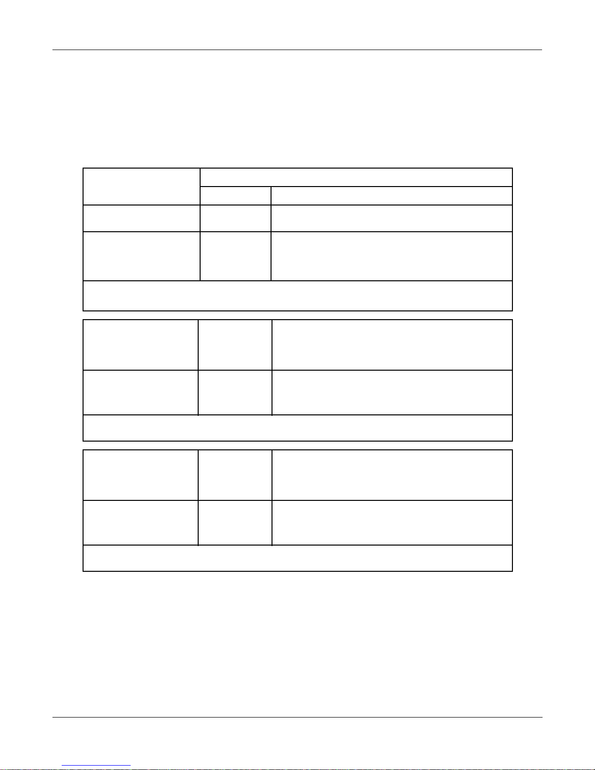
Storing Objects in the Memory Banks
The number of available IDs differs between object types, and depending on whether you are
storing the object to the Zeros bank or one of the other 9 banks.
Programs, Setups, and Keymaps
Storing Objects in the Memory Banks
OBJECT TYPE NUMBER OF OBJECTS AND ID RANGE
IN ROM IN RAM
Sample, Keymap,
Program, Setup 100 1—99 100 200—299
100—199 300—399
.
.
900—999
A total of 999 objects of these types can be stored, 99 of each type in the Zeros bank, and 100 of
each type in every other bank.
Quick Access Banks,
Songs, Velocity Maps,
Pressure Maps,
Intonation Tables 75 1—75 20 100—119
A total of 255 objects of these types can be stored, 75 of each type in the Zeros bank, and 20 of
each type in every other bank.
200—219
.
.
900—919
Preset Effects 37 1—37 10 100—109
200—209
.
.
900—909
A total of 127 preset effects can be stored, 37 in the Zeros bank, and 10 in every other bank.
2-13
Page 28

Programs, Setups, and Keymaps
K2500 ROM Keymaps
K2500 ROM Keymaps
ID# Keymap ID# Keymap ID# Keymap ID# Keymap
0 None 55 Dry Snare 2 104 Jazz Guitar Atk 151 Sawtooth
1 Grand Piano 56 Dry Snare 3 105 Steel Guitar Atk 152 Dull Sawtooth
2 Dual Elec Piano ** 57 Ambient Snare 1 106 Perc Atk 1 153 Very Dull Saw
3 Hard Elec Piano 58 Ambient Snare 2 107 Perc Atk 2 154 Square Wave
4 Soft Elec Piano 59 Ambient Snare 3 108 Perc Atk 3 155 Dull Square
5 Voices 60 Cross Stick 109 Wood Bars 156 Very Dull Square
6 Ensemble Strings 62 10in Dry Tom 110 Solo Strings 157 Buzzy Square
7 Elec Jazz Guitar 63 12in Dry Tom 111 Six String Mutes 158 Buzz Wave
8 Acoustic Guitar 64 15in Dry Tom 112 Oboe Wave 159 Hi Formant Wave
9 5 String Guitar 65 13in Amb Tom 113 Clav Wave 160 PrimeNumber Wave
10 Dual E Bass ** 66 15in Amb Tom 114 Elec Piano Wave 161 Triangle Wave
11 Elec Pick Bass 67 16in Amb Tom 115 Bell Wave 162 Third Wave
12 Elec Slap Bass 68 Reversals 116 Ping Wave 163 Sine Wave
13 Finger Atk Bass 69 Reverse Bell 117 Drawbars 1-3 164 ExtDynPrtls1 ***
14 Flute 71 Bidir Amb Kick 1 118 Drawbars 1-4 165 ExtDynPart2 ***
15 Tenor Saxophone 72 Reverse Snare 119 Drawbars 1-3 Dist 166 ExtDynSaw ***
16 Sax no Altissimo 73 Conga Bass 120 Full Drawbars 167 Mellow Vox
17 Trumpet 74 Conga Slap 121 Drawbars 1-4,8 168 Silence
18 Trombone 75 Conga Tone 122 Organ Wave 1 169 Synflute Brt
19 Trombone/Trumpet 76 Syn Conga Tap 123 Organ Wave 2 170 Synflute mello
20 Bone/Trp 2 77 Timbale 124 Organ Wave 3 171 SlapBass/Guitar
21 Trombet 78 Timbale Shell 125 Organ Wave 4 172 Mello Vox 2
22 Trumpbone 79 Cabasa 126 Organ Wave 5 173 Shift Guitar 2
23 Preview Drums 80 Clave 127 Organ Wave 6 174 Single Mute
24 Dry Kit1 81 Cowbell 128 Organ Wave 7 177 Fingered Bass 2
25 Dry Kit2 82 Tambourine 129 Partials 1-3 178 Ext Dual Bass **
26 Amb Kit 1 83 Handclaps 130 Partials 4-7 179 Syn Bass Pick
27 Amb Kit 2 84 Reverse Crash 131 Partials 8-12 180 Syn Bass Slap
28 Amb Kit 3 85 Reverse Clsd Hat 132 Partials 13-20 181 Shift Guitar
29 2 8ve Dry Kit 86 Reverse Open Hat 133 Partials 21-30 182 Syn Guitar
30 General MIDI Kit 87 Reverse hat loop 134 Partials 1&2 183 Syn Voices
39 Ride Rim Cymbal 88 Chiff 135 Partials 3&4 184 Syn Voices 2
40 Ride Bell Cymbal 89 Chirp 136 Partials 5-7 185 Perc Voice
41 Crash Cymbal 90 FM Bell Trans 137 Partials 8-10 186 Synstrings 1
42 Closed Hihat 91 Waterphone 138 Partials 11-15 187 Synstrings 2
43 Slt Open Hihat 92 Metal Clank 139 Partials 16-21 188 Syn Piano
44 Open Hihat 93 TimbaleShell Atk 140 Partials 2-4 189 Funny Perc
45 Open>Close Hihat 94 Cowbell Atk 141 Partials 5,7,9,11 190 TechnoLoops
46 Foot Close Hihat 95 Timbale Atk 142 Partials 1,2,4 191 Hat Loop
47 Dry Kick 1 96 Bell Attack 143 Partials 1,2,4,6 199 Silence
48 Dry Kick 2 97 Clave Atk 144 Partials 3-5
49 Amb Kick 1 98 Wood Bar Atk 145 Partials 1-3
50 Amb Kick 2 99 Conga Tone Atk 146 Partials 1,3,5
51 Amb Kick 3 100 Conga Slap Atk 147 Partials 1&4
52 DrySnare 1 Soft 101 Elec Pno Atk 148 Partials 1&6
53 DrySnare 1 Hard 102 Brass Attack 149 Partials 1&8
54 Dual Dry Snare 1 ** 103 Bow Attack 150 Partials 1&12
** dual-velocity keymaps
*** triple-velocity keymaps
2-14
Page 29

Effects
List of Factory Preset Global Effects and Their Configurations
Chapter 3
Effects
List of Factory Preset Global Effects and Their Configurations
ID#
1
2 Small Hall Room Simulator
3 Medium Hall Ultimate Reverb
4 Large Hall Ultimate Reverb
5 Big Gym Room Simulator
6 Bright Plate 1 Ultimate Reverb
7 Opera House Ultimate Reverb
8 Live Chamber Room Simulator
9 Bathroom Ultimate Reverb
10 Med Large Room Room Simulator
11 Real Room Ultimate Reverb
12 Drum Room Room Simulator
13 Small Dark Room Room Simulator
14 Small Closet Ultimate Reverb
15 Add Ambience Room Simulator
16 Gated Reverb Gated Reverb
17 Reverse Reverb Reverse Reverb
18 Non-Linear Ultimate Reverb
19 Slapverb Room Simulator
20 Full Bass Chorus+Delay+Room+Mixer
21 Room & Delay Delay+Room+Mixer
22 Delay Big Hall Delay+Hall+Mixer
23 Chorus Room Chorus+Room+Mix
24 Chorus Smallhall Chorus+Hall+Mix
25 Chorus Med Hall Chorus+Hall+Mix
26 Chorus Big Hall Chorus+Hall+Mix
27 Chor-Delay Room Chorus+Delay+Room+Mixer
28 Chor-Dly Hall Chorus+Delay+Hall+Mixer
29 Flange-Dly Room Flange+Delay+Room+Mixer
30 Flange-Dly Hall Flange+Delay+Hall+Mixer
31 Stereo Chorus Stereo Chorus
32 Stereo Flanger Stereo Flange
33 Stereo Delay 4-Tap Delay
34 4 Tap Delay 4-Tap Delay
35 Chorus Delay Parametric EQ+Chorus+Delay+Mixer
36 Flange Delay Parametric EQ+Flange+Delay+Mixer
37 Chorus 4 Tap EQ+Chorus+4 Tap Delay+Mixer
100 Flange 4 Tap EQ+Flange+4 Tap Delay+Mixer
101 Chorus Echo EQ+Chorus+4 Tap Delay+Mixer
102 Chorus Echoverb EQ+Chorus+4 Tap Delay+Mixer
103 Fast Flange Stereo Flange
104 Wash Chorus+Delay+Hall+Mixer
105 Into the Abyss Chorus+Delay+Hall+Mixer
106 Space Flanger EQ+Flange+4 Tap Delay+Mixer
107 Flange Room Flange+Delay+Hall+Mixer
108 Predelay Hall Delay+Hall+Mixer
109 Flange Echo EQ+Flange+4 Tap Delay+Mixer
Name Configuration
Sweet Hall Ultimate Reverb
3-1
Page 30

Effects
Effects Controller Numbers
Effects Controller Numbers
The K2500 uses the Digitech 256 chip for its effects processor. When in Program Mode, the
operating system allows you to assign any MIDI controller to Wet/Dry Mix plus two additional
parameters related to the effect. (The choice of controllable parameters changes depending on
the effect configuration. They are the parameters you see when you go to edit the effect.)
But if the FX Mode parameter on the Effects page is set to Master, then the remapping that takes
place within the program is not applied. Instead, you use a predefined set of controller
numbers. So to control the effects processor in real time when FX Mode is set to Master, you
must use the following controller numbers.
To control the effects processor in this manner, press the EFFECTS button. Change FX Mode to
Master, and set FX Chan to the channel you will use to send the controller info. (You can also
send program changes on this channel to switch effects, so it is usually best to pick a channel
that is not being used for notes.) These settings are remembered as long as the Power Mode
parameter on the MIDI receive page is set to User. Otherwise, you will have to re-enter the
settings each time you power up.
In the following chart, the parameters are grouped by Configuration. Multi FX will contain
parameters found in more than one configuration.
Ultimate Reverb
Decay time 77
Room volume 78
HF damping 14
Envelopment 32
Early Delay 29
Early Diffusion 30
Later Delay n/a
Later Diffusion 93
Dry Level 28
Early Level 31
Later Level 92
Room Simulation
Gross Size 90
Decay Time 15
Listening Position 79
HF Damping 14
Dry Level 28
Reverb Level 88
Reverb in Multi FX
RevPre-Delay 80
Hi-Freq Damp 83
Reverb Decay 82
Revin dry 86
Revin flange 87
Revin Delay 85
3-2
Page 31

Effects
Effects Controller Numbers
Gated Reverb
Pre-Delay 80
Decay Time 38
Envelope 39
Accent Dly 01
Dry Level 57
Accent Level 02
Right Level 62
Left Level 94
Reverse Reverb
Pre-Delay 80
Reverse Time 89
Accent Delay 01
Accent Level 02
Dry Level 57
Right Level 66
Left Level 65
Accent Lvl L 50
Accent Lvl R 51
Parametric EQ
Band 1 Freq 03
Band 1 level 04
Band 2 Freq 05
Band 2 level 06
Band 3 Freq 07
Band 3 level 08
EQ level 58
Graphic EQ
63 Hz 41
125 Hz 43
250 Hz 45
500 Hz 47
1.0 Khz 42
2.0 Khz 44
4.0 Khz 46
8.0 Khz 48
Stereo Chorus
Chorus Delay 10
LFO Speed 13
LFO Depth 12
Dry Level 57
Right Level 54
Left Level 52
Chorus Level 53
3-3
Page 32

Effects
Effects Controller Numbers
Stereo Flange
Flange Delay 33
LFO Speed 37
LFO Depth 36
Feedback 35
Dry Level 57
Right Level 61
Left Level 59
Flange Level 60
Stereo Delay
Delay Time 22
Feedback 17
Dry Level 57
Right Level 56
Left Level 55
DelayDry In 19
Delay Chr In 18
Delay Flg In 21
Delay EQ In 20
Delay EQ Src 16
4 T ap Delay
Tap 1 Delay 24
Tap 2 Delay 25
Tap 3 Delay 26
Tap 4 Delay 27
Feed Delay 23
Feedback 17
Dry Level 57
Tap 1 Level L,R 67, 68
Tap 2 Level L,R 69, 71
Tap 3 Level L,R 72, 74
Tap 4 Level L,R 75, 76
Tap 2 Level 70
Tap 4 Level 73
Other
Wet/Dry Mix 91
Bypass 09
LowPass Filter 49
NOTES:
In the interest of signal to noise performance, the effects dry level parameter should be left at 0
and the Wet/Dry mix (91) should be used instead.
Some of the above parameters may only be found in a Multi FX patch.
3-4
Page 33

LFOs
LFO Shapes
Chapter 4
LFOs
LFO Shapes
LFO Shape Displayed:
Sine Sine
Positive Sine +Sine
Square Square
Positive Square +Squar
Triangle Triang
Positive Triangle +Trian
Rising Sawtooth Rise S
Positive Rising Sawtooth +Rise
Falling Sawtooth Fall S
Positive Falling Sawtooth +Fall
3 Step 3 Step
Positive 3 Step +3 Ste
4 Step 4 Step
Positive 4 step +4 Ste
5 Step 5 Step
Positive 5 Step +5 Ste
6 Step 6 Step
Positive 6 Step +6 Ste
7 Step 7 Step
Positive 7 Step +7 Ste
8 Step 8 Step
Positive 8 Step +8 Ste
10 Step 10 Ste
Positive 10 Step +10 St
12 Step 12 Ste
Positive 12 Step +12 St
4-1
Page 34

LFOs
LFO Shapes
Sine
+1
-1
90°
0° 360° / 0°
+1
-1
90°
0° 360° / 0°
270°
180°
Triangle
270°
180°
Positive Sine
+1
-1
90°
0° 360° / 0°
Positive Triangle
+1
-1
90°
0° 360° / 0°
270°
180°
270°
180°
Sq uare
+1
-1
90°
270°
180°
0° 360° / 0°
Rising Sawtooth
+1
-1
90°
270°
180°
0° 360° / 0°
Positive Sq uare
+1
-1
90°
0° 360° / 0°
Positive Rising Sawtooth
+1
-1
90°
0° 360° / 0°
270°
180°
270°
180°
Falling Sawtooth
+1
-1
90°
0° 360° / 0°
+1
-1
90°
0° 360° / 0°
270°
180°
4 Step
270°
180°
Positive Falling Sawtooth
+1
-1
90°
0° 360° / 0°
Positive 4 Step
+1
-1
90°
0° 360° / 0°
270°
180°
270°
180°
3 Step
+1
-1
90°
270°
180°
0° 360° / 0°
5 Step
+1
-1
90°
0° 360° / 0°
270°
180°
Positive 3 Step
+1
-1
90°
0° 360° / 0°
Positive 5 Step
+1
-1
90°
0° 360° / 0°
270°
180°
270°
180°
4-2
Page 35

LFOs
LFO Shapes
6 Step
+1
-1
90°
270°
180°
0° 360° / 0°
8 Step
+1
-1
90°
0° 360° / 0°
270°
180°
6 Step
Positive Sine
+1
-1
90°
0° 360° / 0°
Positive 8 Step
+1
-1
90°
0° 360° / 0°
270°
180°
270°
180°
7 Step
+1
-1
90°
0° 360° / 0°
+1
-1
90°
0° 360° / 0°
270°
180°
10 Step
270°
180°
Positive 7 Step
+1
-1
90°
270°
180°
0° 360° / 0°
Positive 10 Step
+1
-1
90°
0° 360° / 0°
270°
180°
12 Step
+1
-1
90°
0° 360° / 0°
270°
180°
Positive 12 Step
+1
-1
90°
270°
180°
0° 360° / 0°
4-3
Page 36

LFOs
LFO Shapes
4-4
Page 37

Note Numbers and Intonation Tables
Note Numbers for Percussion Keymaps
Chapter 5
Note Numbers and Intonation Tables
K2500 Note Numbers and MIDI Note Numbers
K2500 MIDI
C -1—B -1 0—11
C 0—B 0 12—23
C 1—B 1 24—35
C 2—B 2 36—47
C 3—B 3 48—59
C 4 (Middle C)—B 4 60—71
C 5—B 5 72—83
C 6—B 6 84—95
C 7—B 7 96—107
C 8—B 8 108—119
C 9—G 9 120—127
You can assign samples to keymaps in the range from C 0 to G 9. The K2500 will respond to
MIDI events in the octave from C -1 to B -1. If a Note On event is generated in the range from C
-1 to B -1, the K2500 will respond by setting the Intonation key correspondingly (C -1 will set it
to C, C# -1 will set it to C#, etc.)
Note Numbers for Percussion Keymaps
Most of the K2500’s percussion programs have keymaps that place the various percussion
timbres at standardized key locations. There are eight drum keymaps: Preview Drums, five 5octave kits (two dry and three ambient), a 2-octave kit, and the General MIDI kit. The keymap
30 General MIDI Kit adheres as closely as possible to the General MIDI standard for placement
of timbres. As a rule, programs that use this keymap can be assigned in percussion tracks for
prerecorded sequences and will play appropriate timbres for all percussion notes.
The timbres are located consistently within the 5-octave kit keymaps so you can interchange
keymaps within percussion programs freely without changing the basic timbres assigned to
various notes (snare sounds will always be at and around Middle C, for example). The note
assignments for the timbres in the 5-octave kit and 2-octave kit keymaps are listed below. MIDI
note number 60 (Middle C) is defined as C 4.
5-Octave Percussion Keymaps (C2 - C7)
MIDI NOTE NUMBER KEY NUMBER SAMPLE ROOT
36-37 C2-C#2 Low Tom
38-39 D2-D#2 Low Mid Tom
40-41 E2-F2 Mid Tom
42-43 F#2-G2 Hi MidTom
44-45 G#2-A2 Mid Hi Tom
46 A#2 Hi Tom
47–51 B 2–D# 3 Kick
52–54 E3–F#3 Snare (Sidestick)
5-1
Page 38

Note Numbers and Intonation Tables
Note Numbers for Percussion Keymaps
55-56 G3-G#3 Low Snare (dual vel. on Dry Kit 1)
57-59 A3-B3 Mid Snare (dual vel. on Dry Kit 1)
60-61 C4-C#4 Hi Snare (dual vel. on Dry Kit 1)
62–64 D 4–E 4 Closed HiHat
65–67 F 4–G 4 Slightly Open HiHat
68–69 G# 4–A 4 Open HiHat
70–71 A# 4–B 4 Open to Closed HiHat
72 C 5 Foot-closed HiHat
73-74 C#5-D5 Low Crash Cymbal
75-78 D#5-F#5 Pitched Crash Cymbals
79 G5 Splash Cymbal
80 G#5 Ride Cymbal (Rim)
81-82 A5-A#5 Ride Cymbal (Rim and Bell)
83-84 B5-C6 Ride Cymbal (Bell)
85 C# 6 Cowbell
86 D 6 Handclap
87 D# 6 Timbale
88 E 6 Timbale Shell
89 F 6 Conga Tone
90 F#6 Conga Bass Hi
91 G 6 Conga Slap
92 G#6 Conga Bass Low
93 A 6 Clave
94 A# 6 Cabasa
95–96 B 6–C 7 Tambourine Shake
2-Octave Percussion Keymaps (C3 - C5)
MIDI NOTE NUMBER KEY NUMBER SAMPLE ROOT
48–49 C 3–C# 3 Kick
50 D 3 Low Tom
51 D# 3 Cowbell
52 E 3 Low Tom
53 F 3 Mid Tom
54 F# 3 Cowbell
55 G 3 Mid Tom
56 G# 3 Timbale
57 A 3 High Tom
58 A# 3 Snare (Sidestick)
59 B 3 High Tom
60-61 C4-C#4 Snare (dual velocity)
62 D 4 Closed HiHat
63 D#4 Ride Cymbal (Rim and Bell)
64 E 4 Closed HiHat
65 F 4 Slightly Open HiHat
66 F# 4 Crash Cymbal
67 G 4 Slightly Open HiHat
68 G# 4 Crash Cymbal
69 A 4 Open HiHat
70 A# 4 Crash Cymbal
71 B 4 Open to Closed HiHat
72 C 5 Foot-closed HiHat
5-2
Page 39

Note Numbers and Intonation Tables
List and Description of Intonation Tables
List and Description of Intonation Tables
1 Equal No detuning of any intervals. The standard for modern western music.
2 Classic Just Tunings are defined based on the ratios of the frequencies between intervals. The origi-
nal tuning of Classical European music.
7th Similar to classic Just, but with the Dominant 7th flatted an additional 15 cents.
3 Just
4 Harmonic The perfect 4th, Tritone, and Dominant 7th are heavily flatted.
5 Just Harmonic
6 Werkmeister Named for its inventor, Andreas Werkmeister. It’s fairly close to equal temperament,
7 1/5th Comma
8 1/4th Comma
9 Indian Raga Based on the tunings for traditional Indian music.
10 Arabic Oriented toward the tunings of Mid-Eastern music.
11 1Bali/Java Based on the pentatonic scale of Balinese and Javanese music.
12 2Bali/Java A variation on 1Bali/Java, slightly more subtle overall.
13 3Bali/Java A more extreme variation.
14 Tibetan Based on the Chinese pentatonic scale.
15 CarlosAlpha Developed by Wendy Carlos, an innovator in microtonal tunings, this intonation table
16 Pyth/aug4 This is a Pythagorean tuning, based on the Greek pentatonic scale. The tritone is 12 cents
17 Pyth/dim5 This is a Pythagorean tuning, based on the Greek pentatonic scale. The tritone is 12 cents
18 Obj v n.n
b
and was developed to enable transposition with less dissonance.
flats each interval increasingly, resulting in an octave with quarter-tone intervals.
sharp.
flat.
Not an intonation table; indicates version number of K2500 ROM objects.
In general, you should select a non-standard intonation table when you’re playing simple
melodies (as opposed to chords) in a particular musical style. When you use intonation tables
based on pentatonic scales, you’ll normally play pentatonic scales to most accurately reproduce
those styles. An excellent reference source for further study of alternative tunings is Tuning In:
Microtonality in Electronic Music , by Scott R. Wilkinson.
5-3
Page 40

Note Numbers and Intonation Tables
List and Description of Intonation Tables
5-4
Page 41

Control Sources
Chapter 6
Control Sources
Control sources are assigned as values for control source parameters, like Src1 and Src2, Depth
Control for Src2, and LFO rate control. Assigning a control source to one of these parameters is
like connecting control source outputs to various inputs on early modular synthesizers. You
can think of each control source parameter as the input to a synthesizer module, and the values
for those parameters as the outputs of modules generating control signals.
For the control sources to have an effect, two things have to happen. First, the control source
must be assigned as the value for (patched to) a control source parameter like Src1. In other
words, for a control source parameter to have an effect, it must be programmed to respond to a
particular control message. Second, the control source must generate a signal. The level of the
control source’s signal determines how much effect it has on the control source parameter to
which it’s assigned.
In terms of generating signals, there are two types of control sources. The first, which might be
called hardware control sources, require some physical movement to transmit them. The
control source called MWheel (MIDI 01) is probably the most prominent example of this type of
control source. When you move your MIDI controller’s Mod Wheel, it sends a Modulation
message (MIDI 01), unless you’ve programmed it to send something else. By default, when the
K2500 receives a MIDI 01 message, it responds by sending a control signal to whatever control
source is assigned as the value for the ModWhl parameter on the MIDI mode RECV page. Of
course, you can program the Mod Whl parameter to send any available control source signal in
response to MIDI 01 messages.
Some of these hardware control sources have physical controls “hard-wired” to transmit them.
That is, there are certain physical controls that always generate these control signals. Every time
you strike one of your MIDI controller’s keys (or pluck a string, or whatever), for example, a
Note on message is generated, along with an Attack velocity message. So any time you strike a
key, any control source parameter that has AttVel assigned as its value will be affected by the
Attack velocity message. Similarly, every time you move the physical Pitch Wheel, a PWheel
message is generated. Whether this affects anything depends on whether you have assigned
any control source parameters to respond to the PWheel message (in other words, whether any
control source parameter has PWheel assigned as its value).
On the MIDI XMIT page (and in the Setup Editor) you’ll find six parameters that correspond to
the standard physical controls found on many keyboard controllers: Mod Wheel, Foot
Switches 1 and 2, the Control Pedal (CPedal), the Controller Slider (Slider), and mono pressure
(Press). As long as the LocalKbdCh parameter on the RECV page in MIDI mode matches the
transmit channel of your MIDI controller, these parameters will always respond to specific
MIDI control messages: ModWhl always responds to Modulation messages (MIDI 01); FtSw1
always responds to Sustain (MIDI 64); FtSw2 always responds to Sostenuto (MIDI 66); CPedal
always responds to Foot (MIDI 04); Slider always responds to Data (MIDI 06); Press always
responds to mono pressure.
The values you assign for these six parameters determine which control messages will be
transmitted to the K2500 and to its MIDI Out port when you move the corresponding controls
on your MIDI controller. If you look at the MIDI XMIT page, you’ll see that the parameter
called ModWhl has a default value of MWheel. You can interpret this as follows: “Moving the
Mod Wheel on my MIDI controller sends the MWheel (Modulation, MIDI 01) message to the
6-1
Page 42

Control Sources
K2500’s sound engine, and, if the K2500’s LocalKbdCh parameter matches my controller’s
transmit channel, to the K2500’s MIDI Out port.”
If you change the value of the ModWhl parameter, the Mod Wheel will no longer send the
MWheel message, and any control source parameter with MWheel assigned as its value will no
longer respond to movement of the Mod Wheel. All of the control assignment parameters on
the MIDI mode XMIT page (and in the Setup Editor) can be programmed to send any of the
MIDI controller numbers. For example, if you assign Foot (MIDI 04) as the value for the Press
parameter , then generating mono pressure messages from your MIDI controller will send a
Foot (MIDI 04) message to the K2500’s sound engine, and will affect any control source
parameter that has Foot assigned as its value. If the value for the K2500’s LocalKbdCh
parameter matches your MIDI controller’s transmit channel, then in this case the Foot message
will be sent to the K2500’s MIDI Out port as well, when you generate mono pressure messages
from your MIDI controller.
The other type of control source is independent of the movement of physical controls. These
control sources generate their control signals internally, and might be called software control
sources. They either run automatically (like A Clock and RandV1), or they’re programmed to
generate their signals according to parameters of their own (as with the LFOs and FUNs). The
software control sources must have some non-zero value set for one or more of their parameters
before they’ll generate control signals.
To summarize, there are two different cases in which you’ll assign control sources. One, the
transmit case, determines what control message will be sent by a particular physical control.
For example, MWheel is set by default to be transmitted by the Mod Wheel. The other case, the
receive case, determines which control message will activate a particular control source
parameter. For example, if you assign MPress as the value for the Src1 parameter on the PITCH
page in the Program Editor, then that layer’s pitch will be affected whenever an MPress
message is generated by any physical control.
Control Source Lists
There’s one long list of control sources stored in the K2500’s memory, although not all control
sources are available for all control source parameters. With time you’ll become familiar with
the types of control sources available for various control source parameters.
The available list of control sources varies depending on the type of control source parameter
you’re programming. There are four basic types: MIDI control sources, local control sources,
global control sources, and FUNs.
When you’re setting the control assignment parameters on the MIDI mode XMIT page or in the
Setup Editor, you’ll see only the portion of the Control Source list that has values appropriate to
MIDI controller messages. Consequently we refer to this subset of the Main Control Source list
as the MIDI Control Source list.
You’ll see variations on the Main Control Source list as you program the other control source
parameters. We’ll explain these variations, but it’s not important that you memorize each
variation. The lists differ to prevent you from assigning a control source where it would be
ineffective. All you have to do is to scroll through the list of control sources available for any
given control source parameter, and choose from the available values.
If you’re programming one of the FUNs, you’ll see the Main Control Source list, which includes
almost every control source from the MIDI Control Source list (with the exception of Data Inc,
Data Dec, and Panic, which belong exclusively to the MIDI Control Source list). The list for the
FUNs also includes a set of constant values, that set an unvarying control signal level for one or
both of the FUN’s inputs.
For most other control source parameters, you’ll see the Main Control Source list (without the
FUN constants and the three special MIDI control sources we mentioned above). There are two
6-2
Page 43

Control Sources
exceptions to this rule, which have to do with global control source parameters. Globals affect
every note in each program’s layer(s). Consequently they can’t use local control sources as their
values, since local control sources affect each note independently.
Four of the control source parameters are always global: the Enable parameter on the LAYER
page (Program Editor), and the three control source parameters on the EFFECT page, (Program
Editor). When programming these parameters, you’ll see the Main Control Source list minus
the three special MIDI control sources, minus the following local control sources:
Note St
Key St
KeyNum
BKeyNum
AttVel
InvAVel
PPress
BPPress
RelVel
Bi-AVel
VTRIG1
VTRIG2
RandV1
RandV2
ASR1
LFO1
FUN1
FUN3
Loop St
PB Rate
AtkSt
Rel St
Finally, if you’ve turned on the Globals parameter on the COMMON page in the Program
Editor, the available values for GLFO2, and the values for GASR2’s trigger will lack the local
control sources listed above, as well as the three special MIDI control sources and the FUN
constants. The available values for GFUN2 and GFUN4 will exclude the same list of local
control sources, but will include the FUN constants.
6-3
Page 44

Control Sources
Descriptions of Control sources
Descriptions of Control sources
This section is organized into two sets of descriptions: the MIDI Control Source list, and the
rest of the control sources. The numeral preceding the name of each control source can be
entered on the alphanumeric pad to select the control source directly (press ENTER after typing
the numeral).
Many of the MIDI control sources are assigned as default values for the control assignment
parameters on the MIDI mode XMIT page and the Setup Editor page. We’ll indicate these
assignments as they appear, simply by mentioning that they’re the default control source for a
control assignment parameter.
MIDI Control Source List
With a few exceptions, the MIDI control sources correspond to the standard MIDI controller
numbers used by every MIDI device.
128 OFF
This value eliminates the effect of any control source parameter to which it’s assigned.
0, 33 MONO PRESSURE (MPress)
Many of the K2500’s factory programs are assigned to modify parameters such as
pitch, filter cutoff frequency, and depth control when MPress messages are received. The mono pressure (Press) control assignment parameters in MIDI and Setup modes are set by default to transmit MPress messages when mono pressure
messages are received from a controller.
1 MIDI 01 (MWheel)
Many factory programs are assigned to respond to MWheel messages. The Mod
Whl parameter in MIDI and Setup modes is set by default to transmit MWheel.
2 MIDI 02 (Breath)
3 MIDI 03
4 MIDI 04 (Foot)
This is the standard MIDI controller number for continuous control foot pedals. It’s
the default value for the CPedal control assignment parameter, so a control pedal
on your MIDI controller which sends MIDI controller 04 messages will send MIDI
controller 04 messages to the K2500 by default.
5 MIDI 05 (PortTim)
This is the standard MIDI controller number for portamento time control. The
K2500 always responds to this control message. For any program that has portamento turned on (on the COMMON page in the Program Editor), MIDI Portamento Time messages received via MIDI will affect the rate of the program’s
portamento.
6 MIDI 06 (Data)
MIDI 06 is the standard MIDI controller number for data entry. The Slider parameter on the MIDI mode XMIT page and in the Setup Editor is set by default to trans-
6-4
Page 45

mit this message, and can be used to select programs and edit parameters on MIDI
slaves if your controller can send it.
7 MIDI 07 (Volume)
This is the standard MIDI controller number for volume. The Volume parameter
on the CHANLS page in MIDI mode will respond to MIDI controller 07 unless the
VolLock parameter is turned on.
8 MIDI 08 (Balance)
9 MIDI 09
10 MIDI 10 (Pan)
MIDI controller 10 is defined as Pan control. The Pan parameter on the CHANLS
page in MIDI mode will respond to MIDI controller 10 unless the PanLock parameter is turned on.
Control Sources
MIDI Control Source List
11 MIDI 11 (Express)
12—14 MIDI 12—14
15 MIDI 15 (AuxBend2)
The K2500 interprets MIDI controller 15 as AuxBend2, which is assigned by default to the short ribbon (below the pitch and mod wheels) on keyboard models of
the instrument. A value of 64 is centered.
16—19 MIDI 16—19 (Ctl A—D)
20 MIDI 20
21 MIDI 21 (AuxBend1)
The K2500 interprets MIDI controller 21 as AuxBend1, which is assigned by default to the long ribbon (above the keyboard) on keyboard models of the instrument. A value of 64 is centered.
22—31 MIDI 22—31
64 MIDI 64 (Sustain)
This is the standard MIDI controller number for Sustain. The control assignment
parameter FootSw1 is set by default to MIDI controller 64, so a switch pedal on
your MIDI controller which sends MIDI 64 will send sustain messages to the K2500
by default. The K2500 will always respond to sustain messages by sustaining currently active notes.
65 MIDI 65 (PortSw)
This is the standard MIDI controller number for Portamento Switch. The Portamento parameter on the COMMON page in the Program Editor always responds
to this controller, and will turn Portamento on for monophonic programs when the
controller signal is at 64 or above. It won’t affect polyphonic programs.
6-5
Page 46

Control Sources
MIDI Control Source List
66 MIDI 66 (SostPD)
67 MIDI 67 (SoftPd)
68 MIDI 68
69 MIDI 69 (FrezPd)
MIDI controller 66 is defined as Sostenuto Switch. The control assignment parameter FootSw2 is set by default to MIDI controller 66, so a switch pedal on your MIDI
controller which sends MIDI 66 will send sostenuto messages to the K2500 by default. The K2500 will always respond to sostenuto messages.
This is the standard MIDI controller number for Soft Pedal. The K2500 will always
respond to Soft pedal messages.
The K2500 will always respond to this message. It causes all notes to be frozen at
their current amplitude levels while the function is on.
70—74 MIDI 70—74
75 MIDI 75 (LegatoSw)
The K2500 always responds to this message. When a MIDI controller 75 message
with a value above 64 is received, the K2500 will force polyphonic programs to be
monophonic.
76—79 MIDI 76—79
80—83 MIDI 80—83 (Ctl E—H)
84—90 MIDI 84—90
91 MIDI 91 (FXDep)
The MIDI specification defines this controller as External Effects Depth. If the FX
Mode parameter is set to Master, and the FX Channel parameter is set to a specific
MIDI channel, the K2500 will respond to this message when it is received on the
FX channel. It responds by adjusting the Wet/Dry mix of the current preset effect.
92—95 MIDI 92—95
96 MIDI 96 (DataInc)
This is defined as Data Increment. It’s intended to be assigned to a switch control.
When the control is on (value 127), the currently selected parameter’s value will be
increased by one increment. This could be assigned to FootSw2, for example, to
scroll through the program list while in Program mode.
97 MIDI 97 (DataDec)
This is defined as Data Decrement. It’s intended to be assigned to a switch control.
When the control is on (value 127), the currently selected parameter’s value will be
decreased by one increment.
123 MIDI 123 (Panic)
The K2500 always responds to this message by sending an All Notes Off and All
Controllers Off message on all 16 MIDI channels.
6-6
Page 47

Main Control Source List
This list contains all but the last three control sources in the MIDI Control Source list. It also
contains the following control sources. All are local unless specified as global.
32 Channel State (Chan St)
Chan St refers to whether any notes are currently active on a given MIDI channel.
Chan St switches on whenever a note is started, and switches off when a Note Off
has been received for each current note on that channel, even if notes are sustained.
33 Mono pressure (MPress)
This is the same as the MPress control source in the MIDI Control Source list, but
is assigned by entering 33 on the alphanumeric pad when used with a parameter
that takes its values from the Main Control Source list.
34 Bipolar mono pressure (BMPress)
Control Sources
Main Control Source List
This control source generates a control signal of -1 when the value of the control to
which it’s assigned is at its minimum, and +1 when the control is at its maximum.
For example, if you had the MPress control assignment parameter assigned to send
BMPress, and you had Src1 on a program layer’s PITCH page assigned to BMPress, with its depth parameter set to 1200 cents, then the layer would be transposed down an octave when no pressure (value 0) was applied to your controller’s
keys (assuming it sends mono pressure). Maximum pressure (value 127) would
transpose the layer up an octave, while a pressure level of 64 would leave the pitch
unchanged.
35 Pitch Wheel message (PWheel)
The K2500 is hard-wired to respond to this message. Any parameter with PWheel
assigned as its value will be affected when your MIDI controller’s Pitch Wheel is
moved.
36 Bipolar Mod Wheel (Bi-Mwl)
This control source will always respond to MIDI controller 01 (MWheel). Control
source parameters set to this value will generate control signals of -1 when the
MIDI controller 01 message value is 0, and will generate a control signal of +1
when the MIDI controller 01 message is at 127, scaling all values in between. For
example, you might set Src1 on a program layer’s PITCH page to a value of BiMwl, and its depth parameter to 1200 cents. Then as long as the ModWhl control
assignment parameter is set to a value of MWheel, your controller’s Mod Wheel
will be bipolar; in this case it will bend the layer’s pitch down as you move the Mod
Wheel toward minimum, and bend the pitch up as you move the Mod Wheel toward maximum.
37 Absolute value of Pitch Wheel (AbsPwl)
This control source always responds to movement of your MIDI controller’s Pitch
Wheel, but makes the Pitch Wheel unipolar. Whereas pulling the Pitch Wheel fully
down usually generates a control signal value of -1, this control source generates a
value of +1 when the Pitch Wheel is pulled fully down.
6-7
Page 48

Control Sources
Main Control Source List
38 Global ASR (GASR2)
39 Global FUN2 (GFUN2)
40 Global LFO (GLFO2)
When the Globals parameter on the COMMON page is turned on, ASR2 becomes
global, and is labeled GASR2. The functions of ASRs are explained in Chapter 6 in
the Performance Guide , in the section “The ASR Page.” This control source does not
appear in the Control Source list for parameters whose functions are local.
When the Globals parameter on the COMMON page is turned on, FUN2 becomes
global, and is labeled GFUN2. The functions of FUNs are explained in Chapter 16
in the Performance Guide . This control source does not appear in the Control Source
list for parameters whose functions are local.
When the Globals parameter on the COMMON page is turned on, LFO2 becomes
global, and is labeled GLFO2. The functions of LFOs are explained in Chapter 6 in
the Performance Guide , in the section “THE LFO PAGE.” This control source does
not appear in the Control Source list for parameters whose functions are local.
41 Global LFO Phase (GLFO2ph)
When the Globals parameter on the COMMON page is turned on, LFO2 becomes
global, and is labeled GLFO2. The functions of LFOs are explained in Chapter 6 in
the Performance Guide , in the section “THE LFO PAGE.” This control source does
not appear in the Control Source list for parameters whose functions are local.
42 Global FUN 4 (GFUN4)
When the Globals parameter on the COMMON page is turned on, FUN 4 becomes
global, and is labeled GFUN4. This control source does not appear in the Control
Source list for parameters whose functions are local.
43 Volume Control (VolCtl)
This control source will always respond to MIDI controller 07 messages. Assign
this value to a parameter when you want MIDI volume messages to affect the parameter.
44 Pan Control (PanCtl)
This control source always responds to MIDI controller 10 messages. Assign this
value to a parameter when you want MIDI pan messages to affect the parameter.
45 Balance Control (BalCtl)
This control source will always respond to MIDI controller 08 messages. Assign
this value to a parameter when you want MIDI balance messages to affect the parameter.
46 Channel Count (ChanCnt)
This control source keeps track of the total number of active voice channels (how
many notes are playing), and converts the number into a control signal between 0
and +1. The control signal’s value is 1 when all 48 voice channels are active, and 0
when no voice channels are active.
You can use this control source in several ways. One example is to limit the volume
of each note so that you have a more nearly constant volume regardless of how
6-8
Page 49

Control Sources
Main Control Source List
many notes you’re playing (this is independent of the effect of attack velocity on
volume). To set this up, you would go to the F4 AMP page in the Program Editor,
and set the Src1 parameter to a value of ChanCnt. Then set the Depth parameter to
a negative value. This will decrease the overall amplitude of each note as you play
more simultaneous notes. This example works best with short-release sounds. It’s
great for an organ program, for example.
Channel count is also useful for controlling the modulation applied to a sound. For
example, you may have a sound what you use both as a lead and for rhythm. Suppose you want a deep vibrato when you’re soloing, but less vibrato when you’re
playing chords. Set up the vibrato by using LFO1 as the value for the Src2 parameter on the PITCH page in the Program Editor. Set the MinDpt parameter to 72 cts,
and the MaxDpt parameter to 12 cts. Then set the value of the DptCtl parameter to
ChanCnt, and You’ll get maximum vibrato depth when only one note is active.
(Channel count outputs a control signal of 0 when no notes are playing, so with
only one note playing, its value is near 0, which causes the DptCtl parameter to
generate a value near its minimum: 72 cents in this case.)
If you want to increase the depth of the vibrato as you increase the number of active notes, set the value of the MaxDpt parameter higher than that of the MinDpt
parameter.
NOTE: There are no control sources that correspond to the numeric entries 47—54.
55 Sync State (SyncSt)
This unipolar control source responds to MIDI clock messages received from an
external MIDI device. Sync State switches on (+1) at each clock start, and switches
off (0) with each clock stop.
56 A Clock
This is a unipolar square wave that responds to MIDI clock messages. It switches
to +1 and back to 0 with every clock beat. This control source looks first for externally received MIDI clock messages, and if none is received, it responds to the
K2500’s internal clock, which is always running. The internal clock speed is set
with the Tempo parameter in Song mode.
57 Negative A Clock (~A Clock)
This is the opposite of A clock, that is, it switches from 0 to +1 with every clock beat
(the square wave is 180 degrees out of phase with that of A Clock).
58 B Clock
This is similar to A Clock, but it’s bipolar—it switches from +1 to -1 with every
clock beat.
59 Negative B Clock (~B Clock)
The opposite of B Clock, this bipolar control source switches from -1 to +1 with every clock beat (the square wave is 180 degrees out of phase with that of B Clock).
60, 61 Global Phase 1 and 2 (G Phase 1, G Phase 2)
These bipolar global control sources are both rising sawtooth waves that rise from
-1 to +1 with each MIDI clock beat. Like A Clock and B clock, they look for an external clock signal, and if none is received, they respond to the K2500’s internal
clock.
6-9
Page 50

Control Sources
Main Control Source List
62, 63 Global Random Variant 1 and 2 (GRandV 1, GRandV 2)
96 Note State (Note St)
These are also bipolar and global, and generate random control signal values between -1 and +1 when assigned to a control source parameter. There is a subtle difference in the randomness of the signals they generate, therefore choosing between
them is a matter of preference.
At any moment, any given note is either on or off; this is its Note State. Note State
can be used as a unipolar control source that responds to each note that’s played.
It switches to +1 when the note starts, and stays on as long as the note is held on
(by the sustain pedal, for example), or by holding down the trigger for that note. It
switches to 0 when the note is no longer sustained by any means. For example, if
you play a note, then hold it with the sustain pedal, its Note State is still on (+1)
even if you’ve released the key that triggered the note. As soon as you release the
sustain pedal, the note’s Note State switches to off (0), even if it has a long release
and you can still hear the release section of the note.
97 Key State (Key St)
This is a unipolar control source that responds to the motion of your MIDI controller’s keys. It switches to +1 when a key is pressed, and switches to 0 when the key
is released. Its effect differs from Note State in that when the key that switched it
on is released, it will switch off even if the note is sustained. If you’re using a nonkeyboard MIDI controller, Key State will switch to 0 when the equivalent of a key
release is sent.
98 Key Number (KeyNum)
This is a unipolar control source that generates its signal value based on the MIDI
key number of each note triggered. That is, it generates a value of 0 in response to
MIDI key number 0, a value of 64 in response to MIDI key number 64, and so on.
Note that some parameters, such as Enable Sense on the Program Editor Layer
Page, will not accept this parameter. GKeyNum, controller number 129, would be
acceptable however.
99 Bipolar Key Number (BKeyNum)
This is like KeyNum, but generates a signal value of -1 in response to MIDI key
number 0, a value of 0 in response to MIDI key number 64, and a value of +1 in
response to MIDI key number 127.
100 Attack V elocity (AttV el)
This unipolar control source responds to Attack velocity values received at the
K2500’s MIDI In port. Velocity values of 0 cause it to generate a signal value of 0,
while velocity values of 127 will generate a value of +1. All other velocity values
will result in signal values proportionally scaled between 0 and +1. Note that some
parameters, such as Enable Sense on the Program Editor Layer Page, will not accept this parameter. GAttVel, controller number 130, would be acceptable however.
101 Inverse Attack Velocity (InvAttVel)
This is the opposite of AttVel, generating a signal value of 0 in response to attack
velocity values of 127.
6-10
Page 51

102 Polyphonic pressure (PPress)
This unipolar control source responds to poly pressure (aftertouch) messages received via MIDI. It generates a signal value scaled from 0 to +1 based on the poly
pressure value range of 0—127.
103 Bipolar polyphonic pressure (BPPress)
This is like PPress, but scales its signal value from -1 to +1.
104 Release V elocity (RelVel)
Also unipolar, this control source scales its signal value from 0 to +1 in response to
release velocity values from 0—127.
105 Bipolar Attack Velocity (Bi-AVel)
This is similar to AttVel, but scales its signal values from -1 to +1.
106, 107 Velocity Triggers 1 and 2 (VTRIG1, VTRIG2)
Control Sources
Main Control Source List
These unipolar control sources are switch controls, that is, they generate signal values of either 0 or +1. These must be programmed in order to have an effect; their
programming parameters are found on the VTRIG page in the Program Editor.
When a VTRIG’s Sense parameter is set to normal, it switches to +1 when a note
plays at a dynamic level exceeding the dynamic level set for its Level parameter.
See “THE VTRIG PAGE” in Chapter 6 in the Performance Guide for more information.
108, 109 Random Variants 1 and 2 (RandV1, RandV2)
These are similar to GRandV1 and GRandV2, but are local, so will affect each control source parameter independently.
110, 111 ASR1, ASR2
These are programmable envelopes with three segments, Attack, Sustain, and Release. Their control source signals are unipolar. See “The ASR Page” in Chapter 6
in the Performance Guide for a thorough explanation.
112, 113 FUN1, FUN2
These generate their control source signals by combining the control signal values
of two programmable inputs, and performing a mathematical function on the result. Their control signals can be unipolar or bipolar, depending on the control
sources assigned as their inputs. See “The FUN Page” in Chapter 6 in the Perfor-
mance Guide . FUN2 becomes global (GFUN2) when the Globals parameter on the
COMMON page in the Program Editor is set to On.
114 LFO1
LFO1 can be unipolar or bipolar depending on the value set for the Shape parameter on its programming page. See “The LFO Page” in Chapter 6 in the Performance
Guide .
115 LFO1 Phase (LFO1ph)
This bipolar control source generates it signal based on the cycle of LFO1. When
the phase of LFO1 is 0 degrees, the signal value of LFO1ph is 0. When the phase of
LFO1 is 90 degrees, the signal value of LFO1ph is 1. When the phase of LFO1 is 180
6-11
Page 52

Control Sources
Main Control Source List
116 LFO2
117 LFO2 Phase (LFO2ph)
118, 119 FUN3, FUN4
degrees, the signal value of LFO1ph is 0. When the phase of LFO1 is 270 degrees,
the signal value of LFO1ph is -1.
This functions exactly the same as LFO1, when the Globals parameter is set to Off
(on the COMMON page in the Program Editor). When the Globals parameter is set
to On, LFO2 becomes global (GLFO2).
This functions exactly the same as LFO1ph, responding to the cycle of LFO2.
These function exactly the same as FUNs 1 and 2, when the Globals parameter is
set to Off (on the COMMON page in the Program Editor). When the Globals parameter is set to On, FUN4 becomes global (GFUN4).
120 Amplitude Envelope (AMPENV)
This programmable unipolar control source lets you vary the effect of a control
source parameter over time. See “The AMPENV Page” in Chapter 6 in the Perfor-
mance Guide .
121, 122 Envelopes 2 and 3 (ENV2, ENV3)
These are programmed in the same way as AMPENV, but they can be bipolar.
123 Loop State (Loop St)
This unipolar control source switches to +1 when the currently playing sample
reaches its LoopStart point. If you’ve programmed a sound with a User amplitude
envelope, Loop St will always be on (+1) for that sound. See Chapter 15 in the Per-
formance Guide for more about sample loops.
124 Sample Playback Rate (PB Rate)
The signal value of this bipolar control source is determined by the sample playback rate of each note. The playback rate is a function of the amount of transposition applied to a sample root to play it at the proper pitch for each note. If you
trigger a note where a sample root is assigned, the PB Rate signal value for that
note is 0. If the note is above the sample root, the sample is transposed upward, and
its playback rate is higher than that of the sample root. Consequently the PB Rate
signal value for that note will be positive. If the note is below the sample root, the
PB Rate signal value will be negative.
125 Attack State (Atk State)
This unipolar control source switches to +1 and back to 0 very quickly with each
note start.
126 Release State (Rel State)
This unipolar control source switches to +1 when a note is released, and stays on
until the note has completed its release (faded to silence), then it switches to 0. It
will stay on if a note is sustained, even if its trigger (key, string, whatever) is released.
6-12
Page 53

127 ON
This generates a constant control signal value of +1.
128 -ON
This generates a constant control signal value of -1 (the numeric entry 128 selects a
value of OFF in the MIDI Control Source list).
129 GKeyNum
Uses the key number (global) to modify whatever it is patched into. Higher notes
will have a very different effect than will lower notes. Users can use this new
Source to control any K2500 parameters such as F/X depth, or to scale amplitude
or pitch.
130 GAttVel
This is updated every time you strike another key (kind of a multi- trigger function). Users can patch this new Source to control parameters such as F/X Depth.
In addition to enabling (triggering) layers from any controller (works like an on/
off switch), users may now set the assigned controller’s threshold (value, or range
of values from 0-127), thus defining the controller’s active range where it will enable the layer.
Control Sources
Main Control Source List
For example, you could create a 32 layer nylon guitar where each layer is assigned
to a different V.A.S.T. Algorithm and each layer is enabled by discrete narrow velocity ranges. This would produce 32 different sounding layers with 32 cross
switch points emulating a picked guitar where no two attacks are exactly alike. If
the layers' velocity ranges were very close together yet not overlapping, you could
create very subtle non-repeating changes. This kind of power usually eludes most
sample playback devices, as this technique uses only one layer of polyphony, due
to cross switching versus cross fading.
131, 132 GHiKey, GLoKey
These control sources work the same as GKeyNum except that they track the highest key currently held and the lowest key currently held respectively. By using one
of these as the only source for pitch tracking, you can create "mono-like" layers
within a polyphonic program.
6-13
Page 54

Control Sources
Constant Control Sources
Constant Control Sources
The remaining control sources are constants, which appear only when you’re assigning control sources as
inputs for the FUNs. Assigning one of these values fixes the input’s control signal value at a steady level.
133 -0.99
134 -0.98
135 -0.97
136-140 -0.96 to -0.92
141 -0.91
142 -0.90
143-145 -0.88 to -0.84
146-150 -0.82 to -0.74
151-155 -0.72 to -0.64
156-160 -0.62 to -0.54
161-165 -0.52 to -0.44
166-170 -0.42 to -0.34
171-175 -0.32 to -0.24
176-180 -0.22 to -0.14
181 -0.12
182 -0.10
183 -0.09
184 -0.08
185 -0.07
186-190 -0.06 to -0.02
191 -0.01
192 0.00
193 0.01
194 0.02
195 0.03
196-200 0.04 to 0.08
201 0.09
202 0.10
203 0.12
204 0.14
205 0.16
206-210 0.18 to 0.26
211-215 0.28 to 0.36
216-220 0.38 to 0.46
221-225 0.48 to 0.56
226-230 0.58 to 0.66
231-235 0.68 to 0.76
236-240 0.78 to 0.86
241 0.88
242 0.90
243 0.91
244 0.92
245 0.93
246-250 0.94 to 0.98
251 0.99
Note: There are no control sources that correspond to numeric entries 252—254.
256 OFF
6-14
Page 55

Control Sources
Keyboard Shortcuts for Control Sources
Keyboard Shortcuts for Control Sources
You can use the keyboard of your MIDI controller to choose control sources, since most key numbers correspond to a value
on the control source list. If you have a certain control source that you use over and over (for example, LFO1), this can be the
quickest way to enter its value. To do this: highlight a parameter which uses a value from the control source list, hold down
ENTER, then strike the key corresponding to the control source you want to choose. LFO1, for example, is assigned to B5.
C-1 to A0
(Below Standard 88-note Keyboard)
C -1
02 - Breath
04 - Foot
06 - Data
07 - Volume
09 - MIDI 09
11 - Expression
12 - MIDI 12
14 - MIDI 14
A0
01 - Mod Wheel
03 - MIDI 03
05 - Portamento Time
08 - Balance
10 - Pan
13 - MIDI 13
15 - MIDI 15
(Standard 88-note Keyboard)
16 - Ctl A
18 - Ctl C
19 - Ctl D
21 - Aux Bend 1
23 - MIDI 23
24 - MIDI 24
26 - MIDI 26
28 - MIDI 28
30 - MIDI 30
31 - OFF
33 - Mono Pressure
35 - Pitch Wheel
36 - Bipolar Mod Wheel
38 - Global ASR (ASR 2)
40 - Global LFO (LFO 2)
42 - Global FUN 2 (FUN 4)
47 - A Clk4
49 - B Clk4
51 - A Clk2
52 - ~A Clk2
54 - –B Clk2
56 - A Clock
58 - B Clock
59 - –B Clk
61 - Global Phase 2
63 - Global Random Variant 2
96 - Note State
98 - Key Number
100 - Attack Velocity
102 - Poly Pressure
103 - Bipolar Poly Pressure
105 - Bipolar Attack Velocity
107- VTRIG 2
108 - Rand Variant 1
110 - ASR 1
112 - FUN 1
114 - LFO 1
115 - LFO 1 Phase
117 - LFO 2 Phase
119 - FUN 4
120 - Amp Envelope
122 - Envelope 3
124 - Sample PB Rate
126 - Release State
127 - ON
129 - GKeyNum
131 - GLowKey
A0 to C8
A0
C4
17 - Ctl B
20 - MIDI 20
22 - MIDI 22
25 - MIDI 25
27 - MIDI 27
29 - MIDI 29
32 - Channel State
34 - Bipolar Mono Pressure
37 - Pitch Wheel Absolute Value
39 - Global FUN (FUN 2)
41 - Global LFO Phase
48 - ~A Clk4
50 - –B Clk4
53 - B Clk2
55 - Sync State
57 - ~A Clk
60 - Global Phase 1
62 - Global Random Variant 1
97 - Key State
99 - Bipolar Key Number
101 - Inverse Attack Velocity
104 - Release Velocity
106 - VTRIG 1
109 - Rand Variant 2
111 - ASR 2
113 - FUN 2
116 - LFO 2
118 - FUN 3
121 - Envelope 2
123 - Loop State
125 - Attack State
128 - GHiKey
130 - GAttVel
6-15
C8
Page 56

Control Sources
Keyboard Shortcuts for Control Sources
6-16
Page 57

DSP Algorithms
Chapter 7
DSP Algorithms
Algorithm|1||||||||||||||||||||||||||||||
|||||||||||||||||||||||||||||||||||||||||
errR®rrterrR®rrrrrrR®rrrrrrR®rrterrR®rrt|
d||||||gk||||||||||||||||||||||gk||||||gh
cvvvvvvbcvvvvvvvvvvvvvvvvvvvvvvbcvvvvvvb|
PITCH HIFREQ STIMULATOR
AMP
PARAMETRIC EQ
STEEP RESONANT BASS
4POLE LOPASS W/SEP
4POLE HIPASS W/SEP
TWIN PEAKS BANDPASS
DOUBLE NOTCH W/SEP
NONE
Algorithm|3||||||||||||||||||||||||||||||
|||||||||||||||||||||||||||||||||||||||||
errR®rrterrR®rrrrrrR®rrtyrrR®rrrrrrR®rrty
d||||||jk||||||||||||||u:||||||||||||||GH
cvvvvvvm,..............M/vvvvvvvvvvvvvvbn
Algorithm|2||||||||||||||||||||||||||||||
|||||||||||||||||||||||||||||||||||||||||
errR®rrterrR®rrrrrrR®rrterrR®rrtYrrR®rrty
d||||||gk||||||||||||||gk||||||G;||||||GH
cvvvvvvbcvvvvvvvvvvvvvvbcvvvvvvbNvvvvvvbn
PITCH
2PARAM SHAPER
AMPPANNER
2POLE LOWPASS
BANDPASS FILT
NOTCH FILTER
2POLE ALLPASS
PARA BASS
PARA TREBLE
PARA MID
NONE
Algorithm|4||||||||||||||||||||||||||||||
|||||||||||||||||||||||||||||||||||||||||
errR®rrterrR®rrrrrrR®rrterrR®rrterrR®rrt|
d||||||gk||||||||||||||gk||||||gk||||||gh
cvvvvvvbcvvvvvvvvvvvvvvbcvvvvvvbcvvvvvvb|
PITCH
2POLE LOWPASS
BANDPASS FILT
NOTCH FILTER
2POLE ALLPASS
NONE
AMP U AMP L2PARAM SHAPER
BAL AMP
PITCH AMP
2PARAM SHAPER LPCLIP
2POLE LOWPASS
BANDPASS FILT
NOTCH FILTER
2POLE ALLPASS
PARA BASS
PARA TREBLE
PARA MID
NONE
SINE+
NOISE+
LOPASS
HIPASS
ALPASS
GAIN
SHAPER
DIST
SW+SHP
SAW+
SW+DST
NONE
7-1
Page 58

DSP Algorithms
Algorithm|5||||||||||||||||||||||||||||||
|||||||||||||||||||||||||||||||||||||||||
errR®rrterrR®rrrrrrR®rrterrR®rrterrR®rrt|
d||||||gk||||||||||||||gk||||||gk||||||gh
cvvvvvvbcvvvvvvvvvvvvvvbcvvvvvvbcvvvvvvb|
PITCH AMP
2PARAM SHAPER
2POLE LOWPASS
BANDPASS FILT
NOTCH FILTER
2POLE ALLPASS
PARA BASS
PARA TREBLE
PARA MID
LP2RES
SHAPE2
BAND2
NOTCH2
LOPAS2
HIPAS2
LPGATE
NONE
NONE
Algorithm|7||||||||||||||||||||||||||||||
|||||||||||||||||||||||5rrrrrrrr6||||||||
errR®rrterrR®rrrrrrR®rrTerrR®rrt7rrR®rrt|
d||||||jk||||||||||||||u?||||||i;||||||gh
cvvvvvvm,..............M/vvvvvvbNvvvvvvb|
Algorithm|6||||||||||||||||||||||||||||||
|||||||||||||||||||||||||||||||||||||||||
errR®rrterrR®rrrrrrR®rrterrR®rrtYrrR®rrt|
d||||||jk||||||||||||||gk||||||u:||||||gh
cvvvvvvm,..............M,......M/vvvvvvb|
PITCH
2PARAM SHAPER LPCLIP
2POLE LOWPASS
BANDPASS FILT
NOTCH FILTER
2POLE ALLPASS
NONE
SINE+
NOISE+
LOPASS
HIPASS
ALPASS
x AMP
+ AMP
! AMP
GAIN
SHAPER
DIST
Algorithm|8||||||||||||||||||||||||||||||
|||||||||||||||||||||||||||||||||||||||||
errR®rrterrR®rrterrR®rrterrR®rrterrR®rrt|
d||||||gk||||||gk||||||gk||||||gk||||||gh
cvvvvvvbcvvvvvvbcvvvvvvbcvvvvvvbcvvvvvvb|
PITCH
2PARAM SHAPER LPCLIP
2POLE LOWPASS
BANDPASS FILT
NOTCH FILTER
2POLE ALLPASS
NONE
SINE+
NOISE+ ! AMP
LOPASS
HIPASS
ALPASS
GAIN
SHAPER
DIST
SINE
LF SIN
SW+SHP
SAW+
SW+DST
NONE
x AMP
+ AMP
PITCH LOPASS
HIPASS
ALPASS
GAIN
SHAPER
DIST
PWM
SINE
LF SIN
SW+SHP
SAW+
SAW
LF SAW
SQUARE
LF SQR
WRAP
NONE
LOPASS
HIPASS
ALPASS
GAIN
SHAPER
DIST
SW+SHP
SAW+
WRAP
NONE
AMPLPCLIP
SINE+
NOISE+
LOPASS
HIPASS
ALPASS
GAIN
SHAPER
DIST
SW+SHP
SAW+
SW+DST
NONE
7-2
Page 59

DSP Algorithms
Algorithm|9||||||||||||||||||||||||||||||
|||||||||||||||||||||||||||||||||||||||||
errR®rrterrR®rrterrR®rrterrR®rrterrR®rrt|
d||||||gk||||||gk||||||gk||||||gk||||||gh
cvvvvvvbcvvvvvvbcvvvvvvbcvvvvvvbcvvvvvvb|
PITCH AMPLOPASS
HIPASS
ALPASS
GAIN
SHAPER
DIST
PWM
SINE
LF SIN
SW+SHP
LOPASS
HIPASS
ALPASS
GAIN
SHAPER
DIST
SW+SHP
SAW+
WRAP
NONE
LP2RES
SHAPE2
BAND2
NOTCH2
LOPAS2
HIPAS2
LPGATE
NONE
SAW+
SAW
LF SAW
SQUARE
LF SQR
WRAP
NONE
Algorithm|10|||||||||||||||||||||||||||||
|||||||||||||||5rrrrrrrr6||||||||||||||||
errR®rrterrR®rrTerrR®rrt7rrR®rrtYrrR®rrt|
d||||||jk||||||u?||||||JU||||||u:||||||gh
cvvvvvvm,......M/vvvvvvm,......M/vvvvvvb|
PITCH LOPASS
HIPASS
ALPASS
GAIN
SHAPER
DIST
PWM
SINE
LF SIN
SW+SHP
SAW+
SAW
LF SAW
SQUARE
LF SQR
WRAP
LOPASS
HIPASS
ALPASS
GAIN
SHAPER
DIST
SINE
LF SIN
SW+SHP
SAW+
SAW
LF SAW
SQUARE
LF SQR
WRAP
NONE
LPCLIP
SINE+
x AMP
+ AMP
NOISE+ ! AMP
LOPASS
HIPASS
ALPASS
GAIN
SHAPER
DIST
SW+SHP
SAW+
SW+DST
NONE
NONE
7-3
Page 60

DSP Algorithms
Algorithm|11|||||||||||||||||||||||||||||
|||||||||||||||5rrrrrrrr6||||||||||||||||
errR®rrterrR®rrTerrR®rrt7rrR®rrtYrrR®rrt|
d||||||gk||||||fk||||||jU||||||u:||||||gh
cvvvvvvbcvvvvvvbcvvvvvvm,......M/vvvvvvb|
PITCH
LOPASS
HIPASS
ALPASS
GAIN
SHAPER
DIST
PWM
SINE
LF SIN
SW+SHP
SAW+
SAW
LF SAW
SQUARE
LF SQR
WRAP
LOPASS
HIPASS
ALPASS
GAIN
SHAPER
DIST
SINE
LF SIN
SW+SHP
SAW+
SAW
LF SAW
SQUARE
LF SQR
WRAP
NONE
LPCLIP
SINE+
x AMP
+ AMP
NOISE+ ! AMP
LOPASS
HIPASS
ALPASS
GAIN
SHAPER
DIST
SINE
LF SIN
SW+SHP
SAW+
SW+DST
NONE
NONE
Algorithm|12|||||||||||||||||||||||||||||
|||||||||||||||||||||||||||||||||||||||||
errR®rrterrR®rrterrR®rrterrR®rrtYrrR®rrt|
d||||||gk||||||jk||||||gk||||||u:||||||gh
cvvvvvvbcvvvvvvm,......M,......M/vvvvvvb|
PITCH LOPASS
HIPASS
ALPASS
GAIN
SHAPER
DIST
PWM
SINE
LF SIN
SW+SHP
SAW+
SAW
LF SAW
SQUARE
LF SQR
WRAP
NONE
LOPASS
HIPASS
ALPASS
GAIN
SHAPER
DIST
PWM
SINE
LF SIN
SW+SHP
SAW+
SAW
LF SAW
SQUARE
LF SQR
WRAP
NONE
LPCLIP
SINE+
NOISE+
LOPASS
HIPASS
ALPASS
GAIN
SHAPER
DIST
SW+SHP
SAW+
SW+DST
NONE
x AMP
+ AMP
! AMP
7-4
Page 61

DSP Algorithms
Algorithm|13|||||||||||||||||||||||||||||
|||||||||||||||||||||||||||||||||||||||||
errR®rrterrR®rrterrR®rrterrR®rrtYrrR®rrty
d||||||gk||||||gk||||||gk||||||G;||||||GH
cvvvvvvbcvvvvvvbcvvvvvvbcvvvvvvbNvvvvvvbn
PITCH AMPPANNERLOPASS
HIPASS
ALPASS
GAIN
SHAPER
DIST
PWM
SINE
LF SIN
SW+SHP
LOPASS
HIPASS
ALPASS
GAIN
SHAPER
DIST
SW+SHP
SAW+
WRAP
NONE
SAW+
SAW
LF SAW
SQUARE
LF SQR
WRAP
NONE
Algorithm|14|||||||||||||||||||||||||||||
|||||||||||||||5rrrrrrrr6||||||||||||||||
errR®rrterrR®rrTerrR®rrt7rrR®rrrrrrR®rrty
d||||||jk||||||u?||||||i;||||||||||||||GH
cvvvvvvm,......M/vvvvvvbNvvvvvvvvvvvvvvbn
PITCH LOPASS
HIPASS
ALPASS
GAIN
SHAPER
DIST
SINE
LF SIN
SW+SHP
SAW+
SAW
LF SAW
SQUARE
LF SQR
WRAP
NONE
LOPASS
HIPASS
ALPASS
GAIN
SHAPER
DIST
SINE
LF SIN
SW+SHP
SAW+
SAW
LF SAW
SQUARE
LF SQR
WRAP
NONE
AMP U AMP L
BAL AMP
7-5
Page 62

DSP Algorithms
Algorithm|15|||||||||||||||||||||||||||||
|||||||||||||||||||||||||||||||||||||||||
errR®rrterrR®rrterrR®rrtYrrR®rrrrrrR®rrty
d||||||gk||||||jk||||||u:||||||||||||||GH
cvvvvvvbcvvvvvvm,......M/vvvvvvvvvvvvvvbn
PITCH LOPASS
HIPASS
ALPASS
GAIN
SHAPER
DIST
PWM
SINE
LF SIN
SW+SHP
SAW+
SAW
LF SAW
SQUARE
LF SQR
WRAP
LOPASS
HIPASS
ALPASS
GAIN
SHAPER
DIST
SINE
LF SIN
SW+SHP
SAW+
SAW
LF SAW
SQUARE
LF SQR
WRAP
NONE
AMP U AMP L
BAL AMP
NONE
Algorithm|16|||||||||||||||||||||||||||||
|||||||||||||||||||||||||||||||||||||||||
errR®rrterrR®rrterrR®rrrrrrR®rrterrR®rrt|
d||||||gk||||||gk||||||||||||||gk||||||gh
cvvvvvvbcvvvvvvbcvvvvvvvvvvvvvvbcvvvvvvb|
PITCH LOPASS
HIPASS
ALPASS
PARA BASS
PARA TREBLE
NONE
AMP
GAIN
SHAPER
DIST
SINE
LF SIN
SW+SHP
SAW+
SAW
LF SAW
SQUARE
LF SQR
WRAP
NONE
7-6
Page 63

DSP Algorithms
Algorithm|17|||||||||||||||||||||||||||||
|||||||||||||||||||||||||||||||||||||||||
errR®rrterrR®rrterrR®rrrrrrR®rrterrR®rrt|
d||||||gk||||||gk||||||||||||||gk||||||gh
cvvvvvvbcvvvvvvbcvvvvvvvvvvvvvvbcvvvvvvb|
PITCH AMPLOPASS
HIPASS
ALPASS
SHAPE MOD OSC
AMP MOD OSC
NONE
GAIN
SHAPER
DIST
PWM
SINE
LF SIN
SW+SHP
SAW+
SAW
LF SAW
SQUARE
LF SQR
WRAP
NONE
Algorithm|18|||||||||||||||||||||||||||||
|||||||||||||||||||||||||||||||||||||||||
errR®rrterrR®rrtYrrR®rrrrrrR®rrterrR®rrt|
d||||||jk||||||u:||||||||||||||gk||||||gh
cvvvvvvm,......M/vvvvvvvvvvvvvvbcvvvvvvb|
PITCH LOPASS
HIPASS
ALPASS
x SHAPEMOD OSC
+ SHAPEMOD OSC
NONE
AMP
GAIN
SHAPER
DIST
SINE
LF SIN
SW+SHP
SAW+
SAW
LF SAW
SQUARE
LF SQR
WRAP
NONE
7-7
Page 64

DSP Algorithms
Algorithm|19|||||||||||||||||||||||||||||
|||||||||||||||||||||||||||||||||||||||||
errR®rrterrR®rrterrR®rrrrrrR®rrterrR®rrt|
d||||||gk||||||gk||||||||||||||gk||||||gh
cvvvvvvbcvvvvvvbcvvvvvvvvvvvvvvbcvvvvvvb|
LOPAS2PITCH AMP
NONE
SHAPE MOD OSC
NONE
Algorithm|20|||||||||||||||||||||||||||||
|||||||||||||||||||||||||||||||||||||||||
errR®rrterrR®rrtYrrR®rrterrR®rrterrR®rrt|
d||||||jk||||||u:||||||gk||||||gk||||||gh
cvvvvvvm,......M/vvvvvvbcvvvvvvbcvvvvvvb|
PITCH LOPASS
HIPASS
ALPASS
GAIN
SHAPER
DIST
SINE
LF SIN
SW+SHP
SAW+
SAW
LF SAW
SQUARE
x GAIN
+ GAIN
XFADE
AMPMOD
NONE
AMPLPCLIP
SINE+
NOISE+
LOPASS
HIPASS
ALPASS
GAIN
SHAPER
DIST
SW+SHP
SAW+
SW+DST
NONE
LF SQR
WRAP
NONE
7-8
Page 65

DSP Algorithms
Algorithm|21|||||||||||||||||||||||||||||
|||||||||||||||||||||||||||||||||||||||||
errR®rrterrR®rrtYrrR®rrterrR®rrterrR®rrt|
d||||||jk||||||u:||||||gk||||||gk||||||gh
cvvvvvvm,......M/vvvvvvbcvvvvvvbcvvvvvvb|
PITCH AMPLOPASS
HIPASS
ALPASS
GAIN
SHAPER
DIST
x GAIN
+ GAIN
XFADE
AMPMOD
NONE
LP2RES
SHAPE2
BAND2
NOTCH2
LOPAS2
HIPAS2
LPGATESINE
LF SIN
NONE
SW+SHP
SAW+
SAW
LF SAW
SQUARE
LF SQR
WRAP
NONE
Algorithm|22|||||||||||||||||||||||||||||
|||||||||||||||5rrrrrrrr6||||||||||||||||
errR®rrterrR®rrTYrrR®rrt7rrR®rrtYrrR®rrt|
d||||||jk||||||u:||||||JU||||||u:||||||gh
cvvvvvvm,......M/vvvvvvm,......M/vvvvvvb|
PITCH LOPASS
HIPASS
ALPASS
GAIN
SHAPER
DIST
SINE
LF SIN
SW+SHP
SAW+
SAW
LF SAW
SQUARE
LF SQR
WRAP
x GAIN
+ GAIN
XFADE
AMPMOD
NONE
LPCLIP
SINE+
NOISE+
LOPASS
HIPASS
ALPASS
GAIN
SHAPER
DIST
SINE
LF SIN
SW+SHP
SAW+
SW+DST
NONE
x AMP
+ AMP
! AMP
NONE
7-9
Page 66

DSP Algorithms
Algorithm|23|||||||||||||||||||||||||||||
|||||||||||||||||||||||||||||||||||||||||
errR®rrterrR®rrtYrrR®rrterrR®rrtYrrR®rrt|
d||||||jk||||||u:||||||jk||||||u:||||||gh
cvvvvvvm,......M/vvvvvvm,......M/vvvvvvb|
PITCH LOPASS
HIPASS
ALPASS
GAIN
SHAPER
DIST
SINE
LF SIN
SW+SHP
SAW+
SAW
LF SAW
SQUARE
LF SQR
WRAP
x GAIN
+ GAIN
XFADE
AMPMOD
NONE
LPCLIP
SINE+
NOISE+
LOPASS
HIPASS
ALPASS
GAIN
SHAPER
DIST
SINE
LF SIN
SW+SHP
SAW+
SW+DST
NONE
x AMP
+ AMP
! AMP
NONE
Algorithm|24|||||||||||||||||||||||||||||
|||||||||||||||||||||||||||||||||||||||||
errR®rrterrR®rrtYrrR®rrterrR®rrtYrrR®rrty
d||||||jk||||||u:||||||gk||||||G;||||||GH
cvvvvvvm,......M/vvvvvvbcvvvvvvbNvvvvvvbn
PANNERPITCH LOPASS
AMP
HIPASS
ALPASS
GAIN
SHAPER
x GAIN
+ GAIN
XFADE
AMPMOD
NONE
DIST
SINE
LF SIN
SW+SHP
SAW+
SAW
LF SAW
SQUARE
LF SQR
WRAP
NONE
7-10
Page 67

DSP Algorithms
Algorithm|25|||||||||||||||||||||||||||||
|||||||||||||||5rrrrrrrr6||||||||||||||||
errR®rrterrR®rrTYrrR®rrt7rrR®rrrrrrR®rrty
d||||||jk||||||u:||||||i;||||||||||||||GH
cvvvvvvm,......M/vvvvvvbNvvvvvvvvvvvvvvbn
PITCH AMP U AMP L
LOPASS
HIPASS
ALPASS
GAIN
SHAPER
x GAIN
+ GAIN
XFADE
AMPMOD
NONE
BAL AMP
DIST
SINE
LF SIN
SW+SHP
SAW+
SAW
LF SAW
SQUARE
LF SQR
WRAP
NONE
Algorithm|26|||||||||||||||||||||||||||||
|||||||||||||||||||||||||||||||||||||||||
||||||||errR®rrterrR®rrterrR®rrtYrrR®rrty
||||||||d||||||©d||||||gk||||||G;||||||GH
||||||||cvvvvvvbcvvvvvvbcvvvvvvbNvvvvvvbn
AMPPANNERSYNC M SYNC S
7-11
Page 68

DSP Algorithms
Algorithm|27|||||||||||||||||||||||||||||
|||||||||||||||||||||||||||||||||||||||||
||||||||errR®rrterrR®rrterrR®rrterrR®rrt|
||||||||d||||||©d||||||gk||||||gk||||||gh
||||||||cvvvvvvbcvvvvvvbcvvvvvvbcvvvvvvb|
LPCLIP
AMPSYNC M SYNC S
SINE+
NOISE+
LOPASS
HIPASS
ALPASS
GAIN
SHAPER
DIST
SINE
LF SIN
SW+SHP
SAW+
SW+DST
NONE
Algorithm|28|||||||||||||||||||||||||||||
|||||||||||||||||||||||||||||||||||||||||
||||||||errR®rrterrR®rrterrR®rrterrR®rrt|
||||||||d||||||©d||||||gk||||||gk||||||gh
||||||||cvvvvvvbcvvvvvvbcvvvvvvbcvvvvvvb|
LP2RES
AMPSYNC M SYNC S
SHAPE2
BAND2
NOTCH2
LOPAS2
HIPAS2
LPGATE
NONE
7-12
Page 69

DSP Algorithms
Algorithm|29|||||||||||||||||||||||||||||
|||||||||||||||||||||||5rrrrrrrr6||||||||
||||||||errR®rrterrR®rrTerrR®rrt7rrR®rrt|
||||||||d||||||jd||||||u?||||||i;||||||gh
||||||||cvvvvvvm,......M/vvvvvvbNvvvvvvb|
SYNC M SYNC S LPCLIP
SINE+
x AMP
+ AMP
NOISE+ ! AMP
LOPASS
HIPASS
ALPASS
GAIN
SHAPER
DIST
SINE
LF SIN
SW+SHP
SAW+
SW+DST
NONE
Algorithm|30|||||||||||||||||||||||||||||
|||||||||||||||||||||||||||||||||||||||||
||||||||errR®rrterrR®rrtYrrR®rrtYrrR®rrt|
||||||||d||||||jd||||||G;||||||u:||||||gh
||||||||cvvvvvvm,......ML......M/vvvvvvb|
SYNC M SYNC S
LPCLIP
SINE+
NOISE+
x AMP
+ AMP
! AMP
LOPASS
HIPASS
ALPASS
GAIN
SHAPER
DIST
SINE
LF SIN
SW+SHP
SAW+
SW+DST
NONE
Algorithm|31|||||||||||||||||||||||||||||
|||||||||||||||||||||||||||||||||||||||||
||||||||errR®rrterrR®rrtYrrR®rrrrrrR®rrty
||||||||d||||||jd||||||u:||||||||||||||GH
||||||||cvvvvvvm,......M/vvvvvvvvvvvvvvbn
SYNC M SYNC S
AMP U AMP L
BAL AMP
7-13
Page 70

DSP Algorithms
7-14
Page 71

Memory Upgrades and Other Options
Program RAM vs. Sample RAM
Chapter 8
Memory Upgrades and Other Options
Program RAM vs. Sample RAM
If you’re creating a lot of your own programs, and using samples loaded from disk, there are a
few things you should be aware of to avoid perplexity. First of all, there’s an important
distinction between what we call Sample RAM and what we call Program RAM. Sample RAM
refers to any SIMMs you may have had installed in your K2500. This RAM is reserved
exclusively for sample storage; nothing else is stored there. Sample RAM is volatile; that is,
when you power down your K2500, the data stored there will “evaporate” almost immediately.
That’s why you have to load RAM samples every time you power up.
The amount of sample RAM in your K2500 is indicated in the center of the top line of the Disk
mode page. If the center of the display’s top line is blank when you’re on this page, it means
that there is no sample RAM installed in your K2500 (or that the K2500 isn’t recognizing it, in
which case you should see your dealer or service center).
Program RAM is where all the other RAM objects you create (programs, setups, QA banks,
songs, keymaps, etc.) are stored. The K2500 comes from the factory with approximately 240K of
available Program RAM. The amount of free Program RAM is indicated at the right side of the
top line of the display in Song mode and Disk mode. You can add a Program RAM (P/RAM)
option to increase your total available Program RAM to about 1250K. Ask your dealer.
Program RAM is battery-backed, so anything that’s stored there will be preserved even when
you power down (as long as your batteries have enough juice). Fresh alkaline batteries will last
up to two years, so you’ll have very few worries about losing your RAM program information.
Nonetheless, we recommend that you back up your programs, songs, etc. by saving them to
disk. This offers insurance in case the RAM becomes corrupted. This is unlikely, but still a
possibility.
If you create a program that uses a disk-loaded sample, the program information (number of
layers, keymap assignment, output group, algorithm, etc.) is stored in Program RAM. All RAM
samples associated with the program are stored in Sample RAM. This means that when you
power down, the RAM samples associated with your programs will disappear. The program
information, however, will remain in Program RAM indefinitely. When you power up again,
your RAM programs will still appear in the display as you scroll through the program list, but
they won’t play if they use RAM samples, because the RAM samples are lost when you power
down.
Viewing RAM Objects
If you’re a heavy Disk mode user, you’ll often be faced with the decision to overwrite, merge, or
append objects when you load files from disk. If you’re loading into a memory bank that’s
nearly full, this can be a tricky call, because if you decide to merge or append, there may not be
enough open slots in the memory bank to accommodate the objects you load. In this case, the
extra objects will be loaded into the next-higher memory bank.
Things get even trickier if you save dependent objects when you save to disk. (A dependent
object is any object that’s associated with another object stored in a different memory bank—for
example, a RAM sample with ID 301 that’s used in a program with ID 200. See the discussion of
dependent objects in Chapter 13 in the Performance Guide .) If you load a file that contains a
number of dependent objects, some of them may be loaded into a higher memory bank than
8-1
Page 72

Memory Upgrades and Other Options
Choosing SIMMs for Sample RAM
the one you specified in the Bank dialog before you loaded the file. A quick way to see where
the objects you loaded ended up is to use the “Objects” Utility function in Master mode.
Select Master mode and press the Utility soft button. Press the Objects soft button, and a list of
RAM objects will appear. Use the Alpha Wheel to scroll through the list of objects. You’ll see the
type, ID, name, and size (in bytes) of each object.
Choosing SIMMs for Sample RAM
Single In-Line Memory Modules, commonly referred to by the acronym "SIMM", are the small
memory cards that the K2500 uses for Sample RAM. You can add up to eight SIMMs to your
K2500, and since they range in available size up to 16 Megabytes, that means you can add up to
128 Megabytes of Sample RAM to your machine.
The K2500 will accept 30-pin non-composite SIMMs, in sizes of 1 Megabyte, 4 Megabytes, and
16 Megabytes, in either 8-bit or 9-bit configurations. The SIMMs must have an access time of 80
nanoseconds (ns) or faster. The maximum height and width of a SIMM for the K2500 is 30mm x
90mm (approximately 1.2 inches x 3.5 inches). Below is a list of some SIMMs that will work
with your K2500:
Hitachi HB56A48A; 4Mx8
Hitachi HB56A49A; 4Mx9
TI TM124EU9B, TM124EU9C; 1Mx9
TI TM497EAD9B, TM4100EAD9; 4Mx9
TI TM4100GAD8, TM497GAD8A; 4Mx8
TI TM16100GBD8;16Mx8
TI TM16100EBD9;16Mx9
NEC MC-421000A8B; 1Mx8
NEC MC-424100A8B; 4Mx8
NEC MC-421000A9B; 1Mx9
NEC MC-424100A9B; 4Mx9
Tosh THM81000AS, Tosh THM81000BS, Tosh THM81070AS; 1Mx8
Tosh THM91000AS, Tosh THM91000BS, Tosh THM91070AS; 1Mx9
SIMMs are always installed in adjacent pairs, and must be installed by an authorized Kurzweil
facility.
CAUTION:
PAL or other additional circuitry to make multiple DRAM chips act like bigger chips. Non-composite
SIMMs (the kind you may use in your K2500) have no chips other than DRAM memory chips soldered
to the board. SIMMs with PALs, buffers, or other logic components will not work in your K2500, and
must not be used.
You must not use composite SIMMs in your K2500. A composite SIMM is one that uses a
Using Headphones with the K2500
A good pair of headphones can be indispensable when you want to play but need to keep the
volume down. You’ll get optimum performance from headphones with at least 50 ohms
impedance, but anything over 8 ohms is adequate. Headphone volume decreases as the
impedance decreases.
8-2
Page 73

Maintenance and Troubleshooting
Battery selection and Replacement
Chapter 9
Maintenance and Troubleshooting
Preventitive Maintenance
With a modicum of care, your K2500 will give you years of use and enjoyment. There are just a
few important points to keep in mind.
Proper installation is essential to the health and welfare of your K2500. It should be mounted in
a standard 19-inch MIDI rack, or should rest on a hard flat surface. In this case it must rest on its
rubber feet, and NOT on the bottom panel. NEVER block the ventilation openings on the rear
panel; doing so can cause overheating that will seriously damage your K2500! To provide
adequate ventilation, the rear panel should be at least four inches from any vertical surface. If
you install an internal hard disk, the ventilation opening on the underside of the K2500 must
remain unobstructed so the cooling fan can operate properly. Care should be taken to minimize
the amount of dust in the environment.
There are no user-serviceable parts in the K2500. Under no circumstances should you attempt
to remove any panels (except for battery replacement). If you attempt to open your K2500,
you’ll risk electric shock, and you’ll void your product warranty.
Cleaning your K2500
It’s a good idea to remove dust from your K2500 occasionally. You may also want to remove
fingerprints. You can clean the K2500’s front panel with a soft damp cloth, and use a mild soap
or detergent. Never use strong cleaners or solvents, and never spray anything on the front
panel or into the ventilation holes! Any cleaners you may want to use should be applied to your
cleaning cloth; you can then carefully wipe the surfaces of the K2500.
Floppy Disk Drive Maintenance
As long as you’re reasonably careful to keep dirt and dust out of the floppy disk drive, you
shouldn’t have any problems. If, however, you start to experience errors or failures in loading
or saving, it may be due to dirt in the floppy drive mechanism. See your dealer for information
regarding products and techniques for floppy drive cleaning.
Battery selection and Replacement
The K2500 uses batteries to preserve its internal memory when the power is turned off. The
original batteries should last up to two years before they need replacing. Replacement is
necessary when the LCD says “BATTERY VOLTAGE IS LOW” during power-up, or when you
notice that the LEDs flash three times instead of once during power-up. Once these warnings
begin to occur, the batteries should be replaced within a couple of weeks to ensure continued
safety of your RAM objects.
To replace the batteries, you’ll need access to the rear panel. Remove the battery compartment
cover, which is located at the lower right corner of the rear panel as you face it. You may wish to
use a small screwdriver. Replace the batteries with three high quality AA size “heavy duty” or
alkaline batteries. A capacitor will keep the memory alive for about 30 seconds while changing
the batteries, so don’t remove the old ones until the new ones are available. Alternatively, it is
permissible to have the power cable plugged in and the power on while changing the batteries,
in which case memory will be retained as long as power is on. Be sure to insert the new
9-1
Page 74

Maintenance and Troubleshooting
User-callable Diagnostics
batteries in the proper direction (the positive terminals should be pointing out). Incorrect
insertion won’t damage anything but the memory won’t receive any power from the batteries.
Most quality brand-name batteries now have “sell by” dates printed on their package. Carbonzinc batteries will last for at least a year after installation while alkaline batteries should last for
at least 2 years provided they are installed before the date on the package. Rechargeable
batteries should not be used; the K2500 will not recharge them and their life after charging on
an external charger will be only a few months. Battery life is not significantly increased by
leaving your K2500 on all the time; batteries may even suffer heat degradation if the K2500 is
left on continuously.
User-callable Diagnostics
There’s an onboard diagnostic program that will enable you to check your battery and confirm
front panel button functions.
To enter the diagnostic program, simply press the 4, 5, and 6 buttons all at once when in
Program Mode. The K2500 will respond by lighting each LED in sequence and then displaying
text such as the following on the LCD:
K2500|SCANNER|DIAGNOSTICS|VERSION|2.1|||
||||||||||||||||||||||||||||||||||||||||
(PRESS"EXIT"|AND|"ENTER"|TO|EXIT)|||||||
||||||||||||||||||||||||||||||||||||||||
BATTERY=4.3VOLTS,|WHEEL|CENTER=128||||||
||||||||||||||||||||||||||||||||||||||||
XXXXXXXXXXXXXXXXXX||||||||||||||||||||||
||||||||||||||||||||||||||||||||||||||||
The battery voltage and wheel center values may be different on your unit. You can ignore the
Wheel Center reading; it doesn’t apply to the K2500. The fourth line (represented by XXXX)
gives a readout identifying the buttons you press.
The diagnostic program can also be used to check out the front panel components. If you move
the Alpha Wheel clockwise, the numbers will go 0-1-2-3-0-1-2...while counterclockwise should
produce 3-2-1-0-3-2-1... If you press a button, its name will be shown and if it is one of the mode
buttons, its associated LED should flash.
The third line of the display shows the results of two measurements that are made whenever
your K2500 is turned on. The battery voltage will be about 4.3 volts for new batteries, gradually
declining over time to 3.2 volts, at which point you will begin to receive warnings (see “Battery
Selection and Replacement” above). The line referring to the Wheel is only relevant to the
keyboard models of the K2500.
Maximizing Music and Minimizing Noise
Your K2500 quite possibly has the lowest noise and widest dynamic range of any instrument in
your studio. The following tips will enable you to make the most of this, and optimize the
K2500’s audio interface to your other equipment.
Setting your audio levels appropriately is the key to optimizing the signal-to-noise ratio of any
piece of equipment. You may have noticed that the K2500’s output signal seems less “hot” than
most other synths when using the unedited factory sounds. This is to allow virtually any
configuration of voice assignment to be used (up to 96 oscillators directed to one output!), and
played very loudly with almost no chance of overload distortion. For more controlled
9-2
Page 75

Maintenance and Troubleshooting
Maximizing Music and Minimizing Noise
adjustments, it’s best to increase the output level digitally (by editing programs) instead of
increasing the gain of your amplifier or mixing board. This is because a digital gain increase is
completely noiseless whereas an analog increase will proportionally increase hum and noise
from the connecting cabling and from the K2500 itself.
Increasing the volume digitally can be accomplished in three different ways. You can increase
the volume of all programs assigned to a given MIDI channel by selecting the CHANLS page in
MIDI mode and setting the OutGain parameter to the desired level (in 6dB steps). For multitimbral sequences (on multiple MIDI channels), you will need to do this for each channel.
Alternatively you can increase the volume of a single program by going to the OUTPUT page
in the Program Editor and setting the Gain parameter to the desired level, again in 6dB steps.
For finer adjustment, the Adjust parameter on the F4 AMP page can be used.
Increasing the level too much can cause clipping distortion when multiple notes are triggered
with high attack velocity. For dense sequences all played through the same outputs, you will
probably only be able to increase the volume by 6dB or so without risk of distortion. For
monophonic instruments (lead guitar) or single instrument tracks (such as drums), a
substantially greater boost is generally possible.
For the absolute maximum signal quality, the individual outputs should be used. These are
connected almost directly to the 18-bit digital-to-analog converters with a minimum of noiseinducing processing circuitry. A total dynamic range of over 100dB is available at these outputs.
The MIX outputs are naturally somewhat noisier because they represent the noise of the
individual outputs all mixed mixed together, and the signal must travel through more circuitry
to reach them.
Programs that are routed through the K2500’s global effects processor (Output Group A) will
also be slightly noisier than programs routed to Output Groups B, C, or D. As with an external
effects unit, maximizing the input signal level (using the methods described above) will
improve the signal-to-noise ratio of the effects processor. When in Effects mode, you’ll see an
internal Wet/Dry mix parameter; in the Effects Editor you’ll find numerous parameters for
setting the level of the various effects. Your best signal-to-noise ratio will be achieved by setting
the effects level parameters to maximum and adjusting the Wet/Dry Mix parameter to set the
overall effects mix. If you are only using the effects unit for EQ functions, one of the EQ or Tone
Control functions accessible through the Program Editor will produce quieter results then the
global effects processor’s EQ functions (Parametric EQ, Para Bass, Para Mid, or Para Treble, for
example).
Ground Hum
A common problem with all electronic musical gear is the hum that can occur in connecting
cables due to AC ground loops. Although “3-prong to 2-prong” AC adaptors are frequently
used to break ground loops, they also break the safety ground that protects you from electric
shock. Using these adaptors is dangerous, and SHOULD NOT be done! Furthermore,
although using these adaptors may reduce low-frequency hum, high-frequency line noise (such
as motor switching noise) is likely to get worse in this case, since the K2500’s AC noise filter
will have no outlet for the noise it filters if you disable the ground.
To reduce ground hum, you can increase your output signal levels as described earlier in this
section. Other safe procedures include plugging your mixing board and amplifier into the same
outlet as your K2500, and making sure that all your gear is properly grounded. If you’re using
an external SCSI device, plug it into the same outlet as well. AC isolation transformers are
extremely effective at eliminating ground loops, and are recommended for critical installations.
A 75-watt transformer is sufficient for the K2500.
For studio applications, where the utmost signal purity is required, using audio unbalanced-tobalanced line transformers will give you the best results. Each of the K2500’s audio outputs can
easily drive a 600-ohm transformer.
9-3
Page 76

Maintenance and Troubleshooting
Power Problems and Solutions
Finally, magnetic fields can be a source of interference. The area surrounding the K2500’s Alpha
Wheel and alphanumeric pad is sensitive to fields from large transformers in power amps; keep
them at least a foot away from the K2500’s front panel. Smaller gear like drum machines and
hardware sequencers can also cause interference.
Power Problems and Solutions
The K2500 is quite tolerant of voltage fluctuations, noise, and transients in the AC power it
receives. The input line filter and grounded power cable will protect against even large
amounts of noise from motors and the like while the built-in filter coupled with the fuse will
protect against all but the largest transients. If your installation is actually suffering from line
noise or transients, most likely your other equipment will be suffering more than your K2500.
Very low line voltage or severe voltage dips are a problem for any computer-based instrument.
When the K2500 is set for 120 volt input (the normal North American setting), it should
function down to 90 volts. If the line voltage drops below 90 volts, a special circuit halts all
activity to protect against software crashes or damage. When the line voltage returns to and
stays at an acceptable level for at least one second, the computer will automatically restart. The
net effect is just as if you had performed a soft reset. Continuous low line voltage or transient
dips will never produce symptoms other than unexpected soft resets as just described. Any
other problems such as distortion, disk errors, or lost data are caused by something other than
line voltage fluctuations.
Soft resets from line voltage dips are most common. These are easily identified because the
reset occurs coincident with the building lights dimming, stage lights or power amps being
switched on, or air-conditioning equipment starting up. The solution in all cases is to get a
more direct connection between your K2500 (and any other computer-based equipment) and
the building’s power. Floodlights, large power amplifiers, and motor-operated devices should
use a separate extension cord; preferably they should be plugged into a separate outlet.
Chronic low line voltage is best confirmed by measurement. Readings below 100-105 volts
mean that even small dips could cause resets, while readings below 95 volts (accounting for
meter inaccuracies) are a definite problem. Again, the best solution is to separate your heavy
lighting and amplifier loads from your K2500 and other synths on separate extension cords or
separate circuits when possible. If the actual building voltage is that low, use of an external
step-up transformer or voltage regulator is recommended. We DO NOT recommend changing
the line voltage selector to 100 volts (or 220 volts in Europe) because overheating or blown fuses
may occur if you leave the K2500 at the lower setting and use it later at a normal voltage level.
Troubleshooting
Naturally, we’ve done everything possible to ensure that your K2500 arrives free of defects.
And there’s a good chance that there’s nothing wrong, even if you’re not seeing the proper
display or hearing the sounds. Carefully check the following things:
Make sure that your power supply is at the right voltage, and is functioning properly.
Make sure the power cable is connected properly.
Adjust the display contrast if necessary (with the Contrast parameter in Master mode). If for
some reason you have trouble reading the display, even after adjusting the Contrast parameter,
you can also adjust the contrast by holding down the ENTER button and turning the Alpha
Wheel. If this improves the contrast, immediately return to the Contrast parameter and adjust it
slightly. This will cause the K2500 to remember the current display contrast level, and should
take care of any difficulties you may have been having. If this procedure doesn’t work, it’s time
to contact your dealer.
9-4
Page 77

Maintenance and Troubleshooting
Troubleshooting
Make sure your audio cables are fully connected to the K2500 and to your sound system. You
may want to switch your audio cables, unless you’re sure they’re functioning properly.
Make sure that your MIDI connections are correct, and that your MIDI cables are functional.
You should have at least one MIDI cable, which should be connected from the MIDI Out port of
your MIDI controller to the MIDI In port of the K2500.
Check that the K2500’s Volume slider is at least partially up.
Check the volume level of your sound system.
Lower the volume of your sound system, and turn the K2500 off, then on again (this is called a
power cycle).
Press the +/-, 0, and Clear buttons (on the alphanumeric pad at the far right of the front panel)
at the same time. This is called a soft reset.
As a last resort, save to disk any RAM objects you’ve created, and perform a hard reset. Do this
by pressing the Master Mode button, then pressing the “Reset” soft button (at the lower right of
the display). The K2500 will warn you about deleting everything (only RAM objects will be
deleted). Press Yes. After a few seconds, the power-up display should appear.
Also check the suggestions on the following pages. If it’s still not happening, the next step is to
shut off the power and call your dealer.
Other Possible Problems
Condition Possible Cause
No sound, no display, no LEDs illuminated.
1 AC line cord not fully inserted into outlet or unit. If using a multiple outlet
box, check its plug.
2 Power not on at AC power source (wall outlet). Check with a different ap-
pliance.
3 Power switch not on (either the unit or multiple outlet box).
4 Incorrect voltage selection setting. REFER TO QUALIFIED SERVICE PER-
SONNEL.
No sound.
1 Volume control turned all the way down on the K2500 or on amplifier or
mixer.
2 Amplifier or mixer not turned on.
3 Cabling is not correct - see Chapter 2 in the Performance Guide - Startup,
and Chapter 18 in the Performance Guide - Audio Outputs. Also check that
amplifier, mixer and speaker cabling is correct.
4 MIDI volume has been assigned to a control source which has sent a value
of 0. Pressing the Panic soft button will reset all controls, and resolve this
problem.
No sound at MIX outputs or headphones.
1 Audio cables are plugged into some or all of the separate outputs. Cables
plugged into of the separate outputs will remove some or all of the audio
signal from the MIX and headphone outputs. See Chapter 18 in the Perfor-
mance Guide —”Audio Output” for output configurations.
9-5
Page 78

Maintenance and Troubleshooting
Troubleshooting
Left MIX output seems louder than Right MIX output when used individually.
Volume knob has no effect.
Programs, Setups, Songs, etc. are missing.
LCD is too dark or too light to read.
Cannot mount or read disk.
Cannot write floppy disk.
Cannot format disk.
1 This is normal. When a cable is plugged into the left MIX output alone,
both the left AND the right audio signals are routed to the jack. When a
cable is plugged into right MIX output alone, only the right channel audio
signal is heard.
1 Separate outputs are in use - the volume knob does not affect the separate
outputs.
2 MIDI volume has been assigned to a control source which has sent a value
of 0.
1 Batteries have run down or have been disconnected. If the batteries have
failed, the message “Battery voltage is low - X.X volts” (where X.X is less
than 3.0) will appear in the display on power-up. All user data will be per-
manently lost if this occurs. See the information on battery selection and
replacement elsewhere in this manual.
1 Contrast not adjusted. Select Master mode and adjust the Contrast param-
eter. If this fails, hold the ENTER button and turn the alpha wheel clockwise to make display darker; counterclockwise to make it lighter. Then
adjust the Master mode Contrast parameter to a higher value if the LCD
was too light, or to a lower value if it was too dark.
1 Disk is not MS-DOS (or Akai, Ensoniq, or Roland) format.
2 Disk is damaged.
1 Disk is not MS-DOS formatted.
2 Disk write protected.
3 Sample is copy protected.
4 Disk is damaged.
1 Disk is damaged.
2 Disk is write protected.
3 You have instructed the K2500 to format a Double density (720K) disk as
a high-density (1.4M) disk. NOTE: Punching a hole in a double-density
disk case to try to make the K2500 read it as a high-density disk is not recommended.
9-6
Page 79

MIDI, SCSI, and Sample Dumps
SCSI Guidelines
Chapter 10
MIDI, SCSI, and Sample Dumps
SCSI Guidelines
The following sections contain information on using SCSI with the K2500, as well as specific
sections dealing with the Mac and the K2500.
Disk Size Restrictions
The K2500 accepts hard disks with up to 2 gigabytes of storage capacity. If you attach an
unformatted disk that is larger than 2 gigabytes, the K2500 will still be able to format it, but
only as a 2 gigabyte disk. If you attach a formatted disk larger than 2 gigabytes, the K2500 will
not be able to work with it; you could reformat the disk, but this - of course - would erase the
disk entirely.
Configuring a SCSI Chain
Here are some basic guidelines to follow when configuring a SCSI chain:
1. According to the SCSI Specification, the maximum SCSI cable length is 6 meters (19.69').
You should limit the total length of all SCSI cables connecting external SCSI devices with
Kurzweil products to 17 feet (5.2 meters). To calculate the total SCSI cable length one
must add up the lengths of all SCSI cables, plus 8" for every external SCSI device
connected. No single cable length in the chain should exceed 8 feet.
2. The first and last device in the chain must be terminated.
The K2500 comes with SCSI termination enabled. You must disable this termination if the
K2500 will be in the middle of a SCSI chain or if you are installing a hard drive into the
K2500.
There are three ways to disable the K2500’s termination, depending on the manufacture
date of the unit. Newer K2500’s have an external "SCSI Termination Enable/Disable"
switch on the rear panel. Older K2500’s require either the removal of SCSI termination
resistors or a jumper setting; these modifications can only be performed by an authorized
service center.
Poor termination is a common cause of SCSI problems. Having more than two terminators
on the bus will overload the bus drivers, but this should not cause permanent damage to
the hardware. Poor termination can corrupt the data on your disk, however, as can bad
SCSI cables.
For the K2500R, if it is not located at one end of a SCSI chain all internal termination,
including the terminator resistor network on the K2500 Engine Board plus terminator
resistors in the internal SCSI drive must be removed. It is much simpler to just make sure
that the K2500 is at one end of the SCSI chain.
For a K2500 keyboard model, it must be at the end of the SCSI chain if it has an internal
disk drive.
A note about active termination - The K2500 uses active termination of the SCSI bus.
Active termination has some benefits over traditional passive termination. Some people
have positioned active termination as a panacea for SCSI problems, but this is more hype
than reality. Active terminators are available to be used at the end of one's SCSI chain and
10-1
Page 80

MIDI, SCSI, and Sample Dumps
SCSI Guidelines
all APS SR2000 series external drives use internal active termination that can be switched
on or off.
3. Each device in the chain (including internal hard drives) must have its own unique SCSI
ID. The default K2500 ID is #6. Macintoshes use ID #7 & #0.
4. Use only true SCSI cables - high quality, twisted pair, shielded SCSI cable. Do not use
RS432 or other non SCSI cables.
The majority of SCSI cables we've tested were poorly made and could damage data
transferred to and from the disk. Nearly all the SCSI data problems Young Chang's
engineering department has had have been due to bad cables that didn't twist pairs of
wires properly. Correctly made SCSI cables have one ground wire for every signal wire
and twist them together in signal/ground pairs. Cables made by APS Technologies (800233-7550) are very good and are highly recommended. Young Chang manufactures 1 and
2 meter 25-25 SCSI cables, that we can also recommend. Good cables are essential to
reliable data transfers to and from the disk drive.
5. You should buy all SCSI cables from a single source to avoid impedance mismatch
between cables.
6. Theoretically all eight SCSI IDs can be used. However, feedback from users has shown us
that many people have problems with more than 5-6 devices in a chain. If you have 7 or 8
devices and are having problems, your best bet is to make sure you have followed all of
the previous information, especially with respect to cables.
7. Connect all SCSI cables before turning on the power on any equipment connected by SCSI
cables. Plugging or unplugging SCSI cables while devices are powered on can cause
damage to your devices or instrument.
8. Authorized service centers should remove termination from the K2500 when installing an
internal drive, set its ID correctly, and terminate the drive.
9. When using a Macintosh, power up the K2500 and other devices first.
10. The K2500 file format is a proprietary format; no other device will be able to read or write
a Kurzweil file.
11. The floppy disk format of the K2500 is DOS. The SCSI disk format is a proprietary form
that is close to DOS, but it is not DOS. Nonetheless, the K2500 can read and write to a DOS
formatted disk provided it was formatted on the PC with no partitions.
12. It is possible to view, copy, move, name, delete files on a K2500 formatted floppy disk or
removable media hard drive, with a PC or Macintosh running a DOS mounting utility
program such as Access PC.
13. As long as the SCSI bus is properly terminated there is no way you can damage your
hardware simply by operating it. There are a few hazards K2500 users should be aware of,
however:
The only damage that usually occurs to SCSI hardware comes from static electricity
"zapping" SCSI connector pins when the cables are disconnected. The silver colored shell
of the SCSI connector on the end of the cable is connected to ground and is safe to touch,
but the brass colored pins inside eventually lead to the SCSI interface chip and are
vulnerable. You should discharge static from your body before touching SCSI connectors
by touching the 1/4" jacks on the rear of the K2500 or another grounded metal object. Any
devices connected to the SCSI bus should be turned off when plugging or unplugging
SCSI cables.
10-2
Page 81

If the K2500 is connected to a Macintosh or PC you should make sure that the computer
cannot access a SCSI disk at the same time the K2500 does (see below for more
information on this). Those who occasionally want to share a drive, but don't want to take
any risks would be best served by disconnecting and connecting devices as needed. If
you want to share drive(s) often and cannot constantly disconnect and reconnect devices,
make sure the Mac or PC is really done with the disk before using the K2500.
Furthermore, you should quit or exit from all running programs and disable screen
savers, email, network file sharing, and any INITs or TSR's that run in the background. If
the computer and K2500 access the disk at the same time there will be no damage to the
hardware, but the bits on the disk, K2500, and computer memory can easily be corrupted.
You may not know that damage has been done to these bits until weird things start to
happen for no apparent reason.
K2500 and Macintosh Computers
1. The Mac really does not like having another SCSI master on the bus (i.e., the K2500). It
assumes that it owns the bus and its drives, therefore it will not tolerate the situation
where the K2500 is trying to talk to its (the Mac's) disk. This suggests that you never want
to select the ID of any drive mounted on the Mac's desktop. Even more fundamental is the
problem that the Mac assumes that the bus is always free, so if it tries to do anything via
SCSI when the K2500 is doing anything via SCSI, the Mac will freak. The only solution is,
wait until your Mac is completely idle before accessing SCSI from the K2500.
MIDI, SCSI, and Sample Dumps
SCSI Guidelines
2. The Mac and the K2500 cannot share a drive in any way, with or without partitions. If you
are using a drive with removable media, you cannot easily switch back and forth between
a Mac formatted volume and a K2500 formatted volume. To prevent problems, you will
need to unmount the drive from the Mac desktop before switching to a K2500 format
volume. The Mac will basically ignore the volume if it's not Mac format, but once you
insert a Mac format volume, the Mac owns it. Don't forget about #1 above; inserting a
cartridge will cause the Mac to access SCSI, so don't try to use the K2K at that moment.
3. The only good reason for connecting the Mac and the K2K on the same SCSI bus is to use
Alchemy or equivalent. If you're using a patch editor or librarian, you can just hook up via
MIDI. Connecting via SCSI will allow fast sample transfers through the SMDI protocol. In
this type of configuration the easiest solution is to let the K2K have its own drive, and the
Mac have it's own drive.
However, we have discovered that when using a K2500 with a Mac and a removable
media drive in the middle of the chain, the following scenario will work:
Start with a Mac formatted cartridge in the drive. When you want to use the K2500, put
the drive to sleep from the K2500. You can then change to a K2500 formatted cartridge and
perform whatever disk operations you need. When you want to go back to the Mac, put
the drive to sleep again, switch cartridges, and then wake up the disk by pressing Load .
Of course the K2500 will tell you it can't read the cart, but the Mac will now access it fine.
10-3
Page 82

MIDI, SCSI, and Sample Dumps
SCSI Guidelines
Accessing a K2500 Internal Drive from the Mac
Access PC is one of the many programs for the Mac which allow it to format, read, and write to
DOS floppy disks and removable SCSI cartridges. However, we have discovered that it is
possible to format internal K2500 hard drives, even though the documentation claims to only
support removable media (not a fixed drive). Because the program claims not to be able to do
this, we do not necessarily recommend it.
The main thing to remember is:
Never change the disk contents (i.e., save or delete files) from the K2500 when the disk is
mounted by the Macintosh. If you do, this could easily lead to trashed files, directories, or even
the entire disk. Access PC has no way of knowing when the K2500 has modified the disk
structure, and it can just overwrite any state of the disk it thinks should be there. The safest
thing is to connect a drive to either the K2500 or the Mac, but not both at the same time. Of
course, you can't always predict when a Mac will access its drive, and it doesn't do SCSI bus
arbitration, so using the Mac while using the SCSI bus from the K2500 (e.g., doing a disk mode
operation) is also a bad idea, and can cause the Mac to hang.
10-4
Page 83

The MIDI Sample Dump Standard
Samples can be transferred between the K2500 and most other samplers and computer
sampling programs using the MIDI Sample Dump Standard.
Due to the relatively slow transfer rate of MIDI data, transferring samples into the K2500 via
the MIDI Sample Dump Standard can take a long time, on the order of a coffee break for a long
sample. Most samplers, synthesizers, and computer software will “freeze up” during this
process, preventing other features of the machine or program from being used. Your K2500,
however, will allow you to continue playing the instrument or using any of its sound editing
features during a MIDI Sample Dump! The transfer takes place in the background; the MIDI
mode LED on the K2500’s front-panel will flash repeatedly during the transfer, so you will
always know if the MIDI Sample Dump is still proceeding. The MIDI mode LED will flash only
when the K2500 is transmitting or receiving a MIDI Sample Dump, or when it receives a MIDI
System Exclusive message.
Note: if you’re using Sound Designer® to transfer samples, you’ll have to offset the sample
number by 2 to transfer the right sample. For example, if you want to dump sample ID 208
from the K2500, then when you begin the sample fetching command from Sound Designer,
instruct it to get sample 210.
MIDI, SCSI, and Sample Dumps
The MIDI Sample Dump Standard
Loading Samples with the MIDI Standard Sample Dump
To load a sample into the K2500 from an external source such as a computer or sampler, first
connect the MIDI Out port of the sampler (or computer) to the K2500’s MIDI In port, and
connect the K2500’s MIDI Out to the MIDI In of the sampler. This is known as a closed-loop
configuration.
Next, access the Sample Dump facility on the sampler. In addition to selecting which sample
you wish to transfer over MIDI, you will need to set the correct sample dump channel number
and destination sample number. The channel number should match the K2500’s SysX ID
parameter (on the RECV page in MIDI mode). If the sampler has no facility for setting the
Sample Dump channel number, try setting the K2500’s SysX ID parameter to 0 or 1.
Alternatively, if you set the SysX ID to 127, the K2500 will accept a MIDI Sample Dump no
matter what Sample Dump channel is used to send the sample dump.
If the sampler has a provision for setting the destination sample number, you can use it to
specify the ID the K2500 will use for storing the sample. The K2500 sample number is mapped
from the destination sample number as follows:
Sample Number K2500 ID
0 uses lowest unassigned ID between 200 and 999.
1-199 adds 200 to the ID (i.e. 5 becomes 205 in the K2500.)
200-999 ID is the same number.
If the sample number maps to a number already assigned to a RAM sample in the K2500, the
RAM sample will be deleted prior to the K2500’s accepting of the new sample load. The K2500
will always map sample number zero to an unassigned ID, and therefore no samples will be
overwritten when zero is specified.
Some computer-based sample editing software limits the sample numbers to a low range such
as 1-128. This conflicts with the K2500, which reserves IDs 1-199 for ROM samples, which
cannot be loaded or dumped. To get around this, the K2500 adds 200 to any numbers between 1
and 199. Therefore, if you want to load a sample into the K2500 at number 219, but your
program can’t transfer samples at numbers greater than 128, specify number 19 (There’s an
exception to this; please see “Troubleshooting a MIDI Sample Dump” later in this section).
10-5
Page 84

MIDI, SCSI, and Sample Dumps
The MIDI Sample Dump Standard
At this point, you’re ready to try loading a sample. See “Accessing a New K2500 Sample” later
in this section to learn how to use samples once they’ve been dumped to the K2500.
Getting a Sample into a Sample Editor from the K2500
Connect the MIDI ports of the K2500 and the computer/sampler in a closed-loop configuration
as described for the Sampler/Computer to K2500 procedure above.
Access the computer software’s “Get Sample” page (it might be called something different). As
with loading a sample into the K2500, the K2500 adds 200 to dump request sample numbers
between 1 and 199. K2500 samples with IDs from 1 to 199 are ROM samples, and cannot be
dumped. Therefore, if you want to get sample number 219 from the K2500 but your program
can’t transfer samples at numbers greater than 128, specify number 19 (There’s an exception to
this; please see “Troubleshooting a MIDI Sample Dump” later in this section).
Loading a Sample into the K2500 from another K2500
Connect the MIDI ports of the two K2500s in a closed-loop configuration as described for the
Sampler/Computer to K2500 procedure above.
On the source K2500, go to the Sample Editor and select the sample you wish to transfer. To do
this, start in Program mode and press EDIT, followed by the KEYMAP soft button. Now you
should be on the KEYMAP page. Now move the cursor to the Sample parameter, use any data
entry method to select the desired sample, then press EDIT.
To start the sample transfer, press the Dump soft button. A dialog will appear, suggesting the
ID for the sample to be dumped to the destination K2500. The source K2500 will suggest the
same ID as it uses for the sample, but you can change the destination ID with any data entry
method. If you choose the default by pressing Yes, the sample will transfer to the same ID on
the destination K2500 as it is on the source K2500.
Dumping from the K2500 to a Sampler
This procedure is the same as dumping a sample from one K2500 to another. This will work
only if the sampler supports the MIDI Sample Dump Standard.
Dumping a Sample from the K2500 to a MIDI Data Recorder
This can be accomplished in an open-loop configuration, by connecting the MIDI Out port of
the K2500 to the MIDI In port of the MIDI Data Recorder. Go to the Sample Editor and select the
K2500 sample you wish to transfer. Set up the MIDI Data Recorder to begin recording, and
press the Dump soft button on the Sample Editor page. This will bring up a dialog allowing
you to change the sample number in the dump if you wish. In most cases, you will just use the
default value. The K2500’s MIDI mode LED will flash while the data transfer is in progress.
Loading a Sample into the K2500 from a MIDI Data Recorder
Connect the MIDI Out port of the Data Recorder to the MIDI In port of the K2500. Load the
appropriate file containing the MIDI Sample Dump data into the Data Recorder, and send the
file. The K2500’s MIDI mode LED will flash during this procedure.
Accessing a New K2500 Sample
First, select the K2500 program you wish to play the new sample from, and press the EDIT
button. Then select the layer you wish (using the CHAN/BANK buttons if necessary), press the
10-6
Page 85

MIDI, SCSI, and Sample Dumps
The MIDI Sample Dump Standard
KEYMAP soft button, and select a keymap. Use the default keymap called “168 Silence” if you
don’t want to alter any existing keymaps.
Now, enter the Keymap Editor by pressing EDIT once again. Use the Sample parameter to
select the new sample. If the new sample was loaded from another K2500, it will have the same
ID as it did on the other K2500. If the sample was loaded from any other source, its ID will be
defined as described above (in the section called “Loading Samples with the MIDI Standard
Sample Dump”).
The name of the sample will be assigned by the K2500 if the sample has been assigned to a
previously unused ID. In most cases, the sample will have a name of “New Sample - C 4”.
The name will be “New Sample! - C 4” (note the exclamation point) if checksum errors were
detected by the K2500. Checksum errors are usually not serious, since they may just mean the
source sampler doesn’t adhere to the MIDI Sample Dump Standard checksum calculation. In
other cases, a checksum error could indicate that the MIDI data flow was interrupted during
the sample transfer.
You can now press EDIT to edit the parameters of the new sample such as Root Key, Volume
Adjust, Pitch Adjust, and Loop Start point. You can also rename the sample. Be sure to save the
parameters you change when you press EXIT. Once the sample is adjusted to your liking, you
can assign it to any Keymap.
Troubleshooting a MIDI Sample Dump
This section will help you identify what has gone wrong if your MIDI sample dumps fail to
work.
WHEN LOADING SAMPLES TO THE K2500
There are two reasons a K2500 will not accept a MIDI Sample Dump. First, a dump will not be
accepted if the destination sample number maps to a K2500 sample that is currently being
edited—that is, if you’re in the Sample Editor, and the currently selected sample has the same
ID as the sample you’re trying to dump. Second, a dump will not be accepted if the length of
the sample to be dumped exceeds the available sample RAM in the K2500. There may be
samples in the K2500 RAM that you can save to disk (if not already saved) and then delete from
RAM to free up sample RAM space. You can delete the current sample by pressing the Delete
soft button while in the Sample Editor.
Note that when you’re loading a sample to an ID that’s already in use, the K2500 will not accept
a MIDI Sample Dump if the length of the sample to be loaded exceeds the amount of available
sample RAM plus the length of the existing sample. If the K2500 accepts the sample load, the
previously existing sample will be deleted.
Also note that certain computer-based editing programs will subtract one from the sample
number when performing MIDI sample transfers to remote devices. So if you instruct these
programs to send a sample to the K2500 as sample ID 204, the program will send the sample as
203. The only way to know if your program behaves in this manner is to try a MIDI Sample
Dump and see what happens.
WHEN DUMPING SAMPLES FROM THE K2500
Certain computer-based sample editing programs subtract one from the sample number when
performing MIDI Sample transfers to remote devices. For instance, if you tell these programs to
get sample number 204, the programs will request that the K2500 dump sample ID 203, which
would ordinarily dump a different sample from the one you intended, possibly causing the
dump to fail. The K2500 automatically counteracts this offset by adding a number to sample
requests. This was done because more sample editing programs create this offset than do not. If
10-7
Page 86

MIDI, SCSI, and Sample Dumps
SMDI Sample Transfers
you find that the K2500 is sending samples with higher IDs than the ones you requested, you
can compensate by requesting the sample ID one lower than the one you want. For example, if
you want the K2500 to dump sample 205, ask for sample 204.
Some samples in the K2500 are copy-protected. These include all ROM samples and possibly
some third-party samples. The K2500 will not dump these samples.
Aborting a MIDI Sample Dump
The Abort soft button in the Sample Editor can be used to cancel any sample load into the
K2500 from an external source (e.g. a computer or a sampler). This button will also halt a
sample dump from the K2500. The K2500 will ask for confirmation before it aborts the sample
dump.
SMDI Sample Transfers
You can use Passport’s Alchemy® and Opcode’s Max® SMDI-capable Macintosh® software
packages to transfer mono and stereo samples to and from the K2500. These applications use
the SMDI data transfer format (SMDI stands for SCSI Musical Data Interchange—pronounced
smiddy . SMDI is parallel, not serial, so sample transfers can be made much faster than with the
MIDI sample dump standard.
Each of these applications has commands for getting and sending samples, which is how you’ll
make the transfer from your offline storage to the K2500. Once the samples have been loaded to
the K2500, you can use the Keymap and Sample Editors as you would with any other sample.
Check your manuals for Alchemy or Max for the specifics.
Keep in mind that when transferring samples via SMDI, the K2500’s sound engine is disabled,
so you can’t play it during a SMDI transfer as you can during a MIDI sample transfer. The
average SMDI sample transfer time is about 20K per second.
As of this writing, the latest versions of Alchemy and Max are the only software packages
supporting SMDI sample transfers to and from the K2500. SMDI is a new technology, however,
and many software developers are working on packages that will support K2500 SMDI sample
transfers. Your Kurzweil/Young Chang dealer can let you know about new developments.
10-8
Page 87

System Exclusive Protocol
K2500 System Exclusive Implementation
Chapter 11
System Exclusive Protocol
K2500 System Exclusive Implementation
The MIDI System Exclusive capabilities of the K2500 allow you to manipulate objects in the
K2500’s memory from a computer system, another K2500, or a MIDI data recorder. The
following is a reference to the SysEx protocol used by the K2500. This information can be used
to build a simple object librarian software program. A word of advice—before you begin
experimenting with SysEx, make sure you have saved anything of value in RAM to disk.
NOTE: To support new features and changes in the K2500 line of products, the internal program
structure has been changed from that of the K2000. Due to these changes, you cannot transfer a K2000
program to a K2500, or a K2500 program to a K2000 via MIDI system exclusive. The K2500 software
will continue to be enhanced, and in the future the K2500 will be capable of accepting K2000 programs
over MIDI. As a result of this, computer based K2000 editor/librarians will not currently work with the
K2500, unless they have been revised to accommodate the changes.
Common Format
In the following discussion, the fields of the K2500 System Exclusive Protocol messages are
notated as…
field(length)
…where ‘field’ is the name of the particular information field in the message, and ‘length’ is
either 1, 2, 3, or n, representing the number of sequential MIDI bytes that make up the field. A
length of ‘n’ means that the field is of a variable length that is determined by its contents or subfields.
All K2500 SysEx messages have the common format:
sox(1) kid(1) dev-id(1) pid(1) msg-type(1) message(n) eox(1)
‘sox’ is always F0h, and represents start of System Exclusive.
‘kid’ must be 07h, and is the Kurzweil Manufacturer ID.
‘dev-id’ is Device ID. The K2500 will recognize a SysEx message if the ‘dev-id’ is the same is the
SysX ID parameter from the MIDI Receive page (from the top level, press the MIDI mode
button and the RECV soft button.) If the K2500’s SysX ID parameter is set to 127, it will
recognize SysEx messages no matter what the ‘dev-id’ is.
‘pid’ is the Product Identifier, and must be 78h (120 decimal), indicating the SysEx message is
for the K2500.
‘msg-type’ is the identifier of one of the K2500 SysEx messages defined below, and ‘message’ is
the variable-length message contents.
‘eox’ is always F7h, for end of System Exclusive.
Data Formats
K2500 SysEx messages are subdivided into fields that contain data in different formats. The
various fields are shown in the Messages section below. Within a message, any fields for values
that can be bigger than 7 bits are broken into 7 bit chunks. Thus two MIDI bytes gives 14 bits,
three bytes gives 21 bits. The significant bits are right justified in the field. All bytes in a field
must be present no matter what the value is. For example, an object type of 132 would be split
into two MIDI bytes in a ‘type’ field as 01 04:
11-1
Page 88

System Exclusive Protocol
K2500 System Exclusive Implementation
decimal: 132
binary: 10000100
binary encoding for type(2) field: 0000001 0000100
decimal encoding for type(2) field: 1 4
Object name fields are sent as a string of ASCII values in a ‘name’ field, with one MIDI byte of
zero as a string terminator. For example, the name “Glass Kazoo” would be sent as letters:
G l a s s _ K a z o o <null>
hex encoding for ‘name’ field: 47 6C 61 73 73 20 4B 61 7A 6F 6F 00
Data sizes and offsets are sent in the ‘size’ and ‘offs’ fields.These values refer to quantities of 8bit bytes in the K2500’s memory, which is packed in the ‘data’ field.
Binary data in the ‘data’ field is sent by in one of two formats, according to the value of the
‘form’ field. If the ‘form’ field equals zero, the data is transmitted as 4 bits or one “nibble” in
every MIDI byte. If the ‘form’ field equals one, then the data is sent as a compressed bit-stream,
with 7 bits per midi byte. The bit-stream format is more efficient for data-transmission, while
the nibble format is easier to read (and write software for).
For example, to send the following four K2500 data bytes,
hex: 4F D8 01 29
decimal: 79 216 1 41
binary: 01001111 11011000 00000001 00101001
eight MIDI bytes are sent in “nibble” format:
hex: 04 0F 0D 08 00 01 02 09
decimal: 4 15 13 80129
binary: 0000100 0001111 0001101 0001000 0000000 0000001 0000010 0001001
five MIDI bytes are sent in bit-stream format:
hex: 27 76 0 12 48
decimal: 39 118 0 18 72
binary: 0100111 1110110 0000000 0010010 1001000
The bit-stream format can be thought of as taking the binary bits of the K2500 data and, starting
from the left, slicing off groups of 7 bits. Note that the trailing bits are set to zero.
After the ‘data’ field, there is another field, ‘xsum’. This is a checksum field which is calculated
as the least significant 7-bits of the sum of all of the MIDI bytes that make up the ‘data’ field.
Messages
This section defines the K2500 System Exclusive message formats. Each message has a message
type (that goes in the ‘msg-type’ field; see Common Format, above), followed by the field
definitions of the message.
11-2
Page 89

System Exclusive Protocol
K2500 System Exclusive Implementation
DUMP = 00h type(2) idno(2) offs(3) size(3) form(1)
…requests the K2500 to send a data dump of an object or portion thereof. ‘type’ and ‘idno’
identify the object. ‘offs’ is the offset from the beginning of the object’s data and ‘size’ describes
how many bytes should be dumped starting from the offset. ‘form’ indicates how the binary
data is to transmitted (0=nibblized, 1=bit stream). The response is a LOAD message:
LOAD = 01h type(2) idno(2) offs(3) size(3) form(1) data(n) xsum(1)
…which writes data into the specified object, which must exist. Both load and dump operate on
the object data only. The response to a load message will be
DACK = 02h type(2) idno(2) offs(3) size(3)
…meaning “load accepted”, or
DNAK = 03h type(2) idno(2) offs(3) size(3) code(1)
…meaning “load not accepted.” The ‘code’ field indicates the cause of the failure, as follows::
code meaning
1 Object is currently being edited
2 Incorrect checksum
3 ID out of range (invalid)
4 Object not found (no object with that ID exists)
5 RAM is full
To request information about an object, use:
DIR = 04h type(2) idno(2)
The ‘type’ and ‘idno’ identify the object. The response is an INFO message:
INFO = 05h type(2) idno(2) size(3) ramf(1) name(n)
This is the response to DIR, NEW, or DEL. If object is not found, ‘size’ will be zero and ‘name’
will be null. ‘ramf’ is 1 if the object is in RAM.
NEW = 06h type(2) idno(2) size(3) mode(1) name(n)
…creates a new object and responds with an INFO message of the created object. The object’s
data will not be initialized to any default values. If ‘idno’ is zero, the first available object ID
number will be assigned. If ‘mode’ is 0, the request will fail if the object exists. If ‘mode’ is 1,
and the object exists in ROM, a RAM copy will be made. If ‘mode’ is 1, and the object exists in
RAM, no action is taken.
DEL = 07h type(2) idno(2)
…deletes an existing object and responds with an INFO message for the deleted object. If there
is only a RAM copy of the object, the response will indicate that the object doesn’t exist
anymore. However, if the deletion of a RAM object uncovers a ROM object, the INFO response
will refer to the ROM object. A ROM object cannot be deleted.
11-3
Page 90

System Exclusive Protocol
K2500 System Exclusive Implementation
CHANGE = 08h type(2) idno(2) newid(2) name(n)
…changes the name and/or ID number of an existing object. If ‘newid’ is zero or ‘newid’ equals
‘idno’, the ID number is not changed. If ‘newid’ is a legal object id number for the object’s type
, then the existing object will be relocated in the database at the new ID number. This will cause
the deletion of any object which was previously assigned to the ‘newid’. If the ‘name’ field is
null, the name will not change. Otherwise, the name is changed to the (null-terminated) string
in the ‘name’ field.
WRITE = 09h type(2) idno(2) size(3) mode(1) name(n) form(1) data(n) xsum(1)
…writes an entire object’s data directly into the database. It functions like the message
sequence DEL followed by NEW followed by a LOAD of one complete object data structure. It
first deletes any object already existing at the same type/ID. If no RAM object currently exists
there, a new one will be allocated and the data will be written into it. The object name will be
set if the ‘name’ string is non-null. The response to this message will either be a DACK or a
DNAK, as with the load message. The ‘offs’ field of the response will be zero. The K2500 will
send a WRITE message whenever an object is dumped from the front-panel (using a “Dump”
soft-button), or in response to a READ message.
The ‘mode’ field is used to determine how the ‘idno’ field is interpreted.
If ‘mode’ = 0:
The ‘idno’ specifies the absolute ID number to write to, which must exist.(must be valid)
If ‘idno’ equals zero, write to the first available ID number.
If ‘mode’ = 1
The object is written at the first available ID number after what is specified by ‘idno’.
It doesn’t matter if ‘idno’ is a legal ID number. Remember that for certain object types, the 100s
through 900s banks allow fewer than 100 objects to be stored (for example, the 100s bank will
store preset effects at IDs 100—109 only). In this mode, if ‘idno’ was 313, the object would be
written to ID 400 if available.
READ = 0Ah type(2) idno(2) form(1)
…requests the K2500 to send a WRITE message for the given object. No response will be sent if
the object does not exist.
READBANK = 0Bh type(2) bank(1) form(1) ramonly(1)
…requests the K2500 to send a WRITE message for multiple objects within one or all banks.
‘type’ and ‘bank’ specify the group of objects to be returned in WRITE messages. The ‘type’
field specifies a single object type, unless it is zero, in which case objects of all user types will be
returned (see object type table below). The ‘bank’ field specifies a single bank, 0-9, unless it is
set to 127, in which case objects from all banks will be returned.
‘form’ requests the format of the binary data in the WRITE messages. If ‘ramonly’ is one, only
objects in RAM will be returned. If ‘ramonly’ is zero, both RAM and ROM objects are returned.
11-4
Page 91

System Exclusive Protocol
K2500 System Exclusive Implementation
The responses, a stream of complete WRITE messages, will come out in order of object type,
while objects of a given type are in order by ID number, from lowest to highest. If no objects are
found that match the specifications, no WRITE messages will be returned. After the last WRITE
message, an ENDOFBANK message (defined below) is sent to indicate the completion of the
bank dump.
The K2500 will insert a small delay (50ms) between WRITE messages that it issues in response
to a READBANK message.
A bank dump can be sent in its entirety to another K2500, which will add all of the objects
contained in the dump to its own object database. IMPORTANT: If the K2500 receives a large
bank dump for a bank or banks that already contain objects, errors may result unless the sender
waits for the DACK message before sending the next object’s WRITE message. One way to
avoid transmission errors such as this is to make sure that the bank being dumped is clear in
the K2500 before sending the dump, so that the K2500 will not miss parts of the dump while its
CPU is busy deleting already existing objects. This can be done using the DELBANK message
(defined below). If the destination bank in the K2500 is pre-cleared, it is not necessary to wait
for the DACK before sending. Even if the sender chooses not to wait for the DACK before
sending the next message, it may be necessary to preserve the 50ms delay between the WRITE
messages.
Due to the large amount of incoming data during a bank dump containing many objects, the
receiving K2500 may have a more sluggish response to front-panel use and keyboard playing
during the data transfer. This is normal behavior and the machine will become fully responsive
as soon as the dump is finished.
DIRBANK = 0Ch type(2) bank(1) ramonly(1)
This is similar to the READBANK message. The DIRBANK message requests an INFO message
(containing object size, name, and memory information) be returned for each object meeting
the specifications in the ‘type’ and ‘bank’ fields. Following the last INFO response will be an
ENDOFBANK message.
ENDOFBANK = 0Dhtype(2) bank(1)
This message is returned after the last WRITE or INFO response to a READBANK or
DIRBANK message. If no objects matched the specifications in one of these messages,
ENDOFBANK will be the only response.
DELBANK = 0Eh type(2) bank(1)
This message will cause banks of objects (of one or all types) to be deleted from RAM. The
‘type’ and ‘bank’ specifications are the same as for the READBANK message. The deletion will
take place with no confirmation. Specifically, the sender of this message could just as easily
delete every RAM object from the K2500 (e.g. ‘type’ = 0 and ‘bank’ = 127) as it could delete all
effects from bank 7 (e.g. ‘type’ = 113, ‘bank’ = 7.)
MOVEBANK = 0Fh type(2) bank(1) newbank(1)
This message is used to move entire banks of RAM objects from one bank to another. A specific
object type may be selected with the “type” field. Otherwise, if the “type” field is unspecified
(0), all object types in the bank will be moved. The “bank” and “newbank” fields must be
between 0 and 9. The acknowledgement is an ENDOFBANK message, with the “bank” field
11-5
Page 92

System Exclusive Protocol
K2500 System Exclusive Implementation
equal to the new bank number. If the operation can’t be completed because of a bad type or
bank number, the ENDOFBANK message will specify the old bank number.
LOADMACRO = 10h
…tells K2500 to load in the macro currently in memory.
MACRODONE = 11h code(1)
…acknowledges loading of macro. Code 0 indicates success; code 1 means failure.
PANEL = 14h buttons(3n)
…sends a sequence of front-panel button presses that are interpreted by the K2500 as if the
buttons were pressed at its front-panel. The button codes are listed in a table at the end of this
chapter. The K2500 will send these messages if the Buttons parameter on the XMIT page in
MIDI mode is set to On. Each button press is 3 bytes in the message. The PANEL message can
include as many 3-byte segments as necessary.
Byte 1 Button event type:
08h Button up
09h Button down
0Ah Button repeat
0Dh Alpha Wheel
Byte 2 Button number (see table)
Byte 3 Repeat count (number of clicks) for Alpha Wheel; the count is the delta (difference)
from 64—that is, the value of the byte minus 64 equals the number of clicks. A Byte
3 value of 46h (70 dec) equates to 6 clicks to the right. A Byte 3 value of 3Ah (58
dec) equates to six clicks to the left. For example, the equivalent of 6 clicks to the
right would be the following message:
(header) 14h 0Dh 40h 46 (eox)
For efficiency, multiple button presses should be handled by sending multiple Button down
bytes followed by a single Button up byte (for incrementing with the ‘+’ button, for instance. )
Object Types
These are the object types and the values that represent them in ‘type’ fields:
Type ID (decimal) ID (hex) ID(hex, ‘type’ field)
Program 132 84h 01h 04h
Keymap 133 85h 01h 05h
Effect 113 71h 00h 71h
Song 112 70h 00h 70h
Setup 135 87h 01h 07h
Soundblock 134 86h 01h 06h
Velocity Map 104 68h 00h 68h
Pressure Map 105 69h 00h 69h
11-6
Page 93

System Exclusive Protocol
K2500 System Exclusive Implementation
Quick Access Bank 111 6Fh 00h 6Fh
Intonation Table 103 67h 00h 67h
Master Parameters
The Master parameters can be accessed as type 100 (00h 64h), ID number 16. Master parameters
cannot be accessed with any of the Bank messages.
Button Press Equivalence Table
Button
Code (hex) Button Code(hex)
Alphanumeric pad Soft-Buttons ‘A-F’
zero 00 A ‘(leftmost) 22
one 01 B 23
two 02 C 24
three 03 D 25
four 04 E 26
five 05 F (rightmost) 27
six 06 AB 28
seven 07 CD (two center) 29
eight 08 EF 2A
nine 09 YES 26
+/- 0A NO 27
Alphanumeric pad Edit/Exit
CANCEL 0B EDIT 20
CLEAR 0C EXIT 21
ENTER 0D
Navigation Mode Selection
Plus (+) 16 PROGRAM 40
Minus (-) 17 SETUP 41
Plus and Minus 1E QUICK ACCESS 42
CHAN/BANK Inc 14 EFFECTS 47
CHAN/BANK Dec 15 MIDI 44
CHAN/BANK Inc/Dec 1C MASTER 43
Cursor Left 12 SONG 46
Cursor Right 13 DISK 45
Cursor Left/Right 1A
Cursor Up 10
Cursor Down 11
11-7
Page 94

System Exclusive Protocol
K2500 System Exclusive Implementation
Cursor Up/Down 18
The next four commands allow you to read the screen display, both text and graphics layers.
ALLTEXT = 15h
…requests all text in the K2500’s display.
PARAMVALUE = 16h
…requests the current parameter value.
PARAMNAME = 17h
…requests the current parameter name.
GETGRAPHICS = 18h
…requests the current graphics layer.
SCREENREPLY = 19h
This is the reply to ALLTEXT, PARAMVAL, PARAMNAME, GETGRAPHICS, or
SCREENREPLY.
The reply to ALLTEXT will be 320 bytes of ASCII text (the display has 8 rows of 40 characters
each). If you receive less than that, then the screen was in the middle of redrawing and you
should request the display again.
The reply to PARAMVALUE will be a variable length ASCII text string. Some values (like
keymaps, programs, samples, etc.) include their ID number in the text string (e.g., "983 OB
Wave 1"). Some messages are also padded with extra spaces.
The reply to PARAMNAME will be a variable length ASCII text string. In cases where there is
no parameter name (like on the program page) there will just be the single 00 null terminator.
The reply to GETGRAPHICS will be 2560 bytes of information. The 6 least significant bits of
each byte indicate whether a pixel is on or off. If pixels are on over characters, the text becomes
inverted. Characters on the K2500 display are a monospaced font with a height of 8 pixels and
a width of 6 pixels.
11-8
Page 95

Glossary
Chapter 12
Glossary
Algorithm
Aliasing
Amplitude
Analog
Bandwidth
Bank
Cent
In the K2500, a preset configuration of programmable digital signal processing
functions. Each of a program’s layers uses its own algorithm, which determines the
type of synthesis each layer uses to generate its sound.
A type of distortion that occurs in digitally sampled sounds when higher pitches
(increased sample playback rates) introduce partials that were not present in the
original sound. These partials may or may not be musically useful.
The intensity of a signal, perceived as loudness in the case of audio signals.
A term used widely in electronics-related fields to describe a method of representing
information, in which the method of representation resembles the information itself.
Analog synthesizers, for example, use gradual variations in electrical voltage to create
and modify sounds. The oscillations in voltage are analogous to the waveforms of the
sounds they generate. Compare Digital.
In terms of sound generation, the range of frequencies within which a device
functions. The human ear has a “bandwidth” of almost 20 KHz (it can distinguish
sound at frequencies from 20 Hz to 20KHz). The K2500’s 20KHz bandwidth enables it
to produce sounds that span the entire range of humanly audible sound.
There are two types of banks in the K2500’s memory: memory banks, which store and
organize the programs and other objects you create, and Quick Access banks, where
you can store programs and setups for one-button access while in Quick Access mode.
1/100th of a semitone. The standard increment for fine adjustment of pitch.
Continuous control
Control Source
DSP
DSP Functions
Default
A device that converts motion into a range of 128 possible values that can modulate a
sound source. The Mod Wheel, a standard volume pedal, and controllers like Breath
and Aftertouch are continuous controls. Compare switch controls.
Anything that can be used to modify some aspect of a program’s sound. LFOs,
envelopes, Mod Wheel messages (MIDI 01), and FUNs are just a few examples of the
K2500’s control sources.
Digital signal processing (see)
The K2500’s collection of digital signal processing functions are what give the Variable
Architecture Synthesis system its flexibility. Within each layer’s algorithm, you can
select from a long list of DSP functions like filters, EQ, oscillators, and a few that are
unique to the K2500. Each DSP function has a corresponding page that enables you to
assign numerous control sources to define how the DSP functions affect the sound of
the program you’re editing.
The starting condition of a system. The settings for the K2500’s parameters are at their
defaults when you unpack it, and they stay there until you change them. A hard reset
will erase RAM and restore all parameters to their defaults.
12-1
Page 96

Glossary
Dialog
Digital
Digital Signal
Processing
Drum Program
A page that prompts you to enter information that the K2500 needs in order to execute
an operation. Dialogs appear, for example, when you initiate a Save or Delete
operation.
A term used widely in electronics-related fields to describe a method of representing
information as a series of binary digits (bits)—1s and 0s. Digital computers process
these strings of 1s and 0s by converting them into an electrical signal that is always in
one of two very definite states: “on” or “off.” This is much more precise than the
analog method, therefore digital computers can operate at speeds unattainable by
analog devices. Digital synthesizers like the K2500 are actually computers that process
vast strings of digital information signals, eventually converting them (at the audio
output) into the analog signals that flow into PAs and other audio systems. See also
Analog.
The term “Signal processing” refers to a vast range of functions, all of which have in
common the fact that they act upon an electric current as it flows through a circuit or
group of circuits. A simple form of signal processing is the distortion box used by
many guitarists. Digital signal processing refers to similar processes that are
performed by digital (see) circuitry as opposed to analog (see) circuitry. Many of the
effects devices available today use digital signal processing techniques.
The only difference between a drum program and an ordinary program is that a drum
program can contain up to 32 layers instead of the usual maximum of three. Since
each layer has its own keymap and algorithm (not to mention all the other control
sources), this gives you enormous control over whatever sounds you assign to the
layers in a drum program.
Editor
Envelope
File
Global
Hard Reset
Keymap
The complete set of parameters used to modify a particular aspect of the K2500, for
example, the currently selected Program, which is modified with the Program Editor.
The Program Editor spans several display pages, which can be viewed by using the
soft buttons (the ones labeled “<more>.”
An aperiodic modifier. In other words, a way to cause a sound to change over time
without repeating the change (unlike periodic modifiers like LFOs, which repeat at
regular intervals).
A group of objects stored to a floppy or hard disk, or loaded into the K2500’s RAM
from disk.
In this manual, used primarily in reference to control sources. A global control source
affects all notes in a layer uniformly. If a layer uses a global control source, that control
source begins to run as soon as the program containing it is selected. Its effect on each
note will be completely in phase, regardless how many notes are being played.
Compare Local.
Resets all parameter values to their defaults, and completely erases the contents of
RAM. Press the Reset button in Master mode to do a hard reset. This is a quick way to
restore the factory defaults to your K2500, but EVERYTHING in RAM (all the objects
you’ve created) will be erased, so objects you wish to keep should be saved to disk or
SyxEx dump. A hard reset should not be used to recover if your K2500 is hung up,
except as a last resort. See Soft Reset.
A keymap is a collection of samples assigned to specific notes and attack velocities.
Keymaps usually contain numerous sample roots pitch-shifted across a range of
several notes. When you trigger a note, the keymap tells the K2500 what sound to
play, at what pitch, and at what loudness.
12-2
Page 97

Glossary
LFO
Layer
Leslie effect
Local
Memory banks
Low frequency oscillator. An oscillator is an electrical signal that cycles regularly
between a minimum and maximum amplitude. The simplest oscillating waveform is
the sine wave, but an LFO waveform can have almost any shape. The number of times
each second that an oscillator repeats itself is called its frequency, which is measured
in Hertz (Hz). Anything up to 50 Hz is considered low-frequency in musical
applications. Use an LFO whenever you want to generate a periodic (repeating) effect.
Adjusting the rate of the LFO will change the repetition rate of the effect.
A layer consists of a keymap processed through an algorithm. Layers can be stacked
together within a program. Each layer uses one of the K2500’s 48 available voices.
Each K2500 program can contain up to three layers—except drum channel programs,
which can contain up to 32 layers.
This classic vibrato effect was originally created by mounting a speaker in its cabinet
so the speaker could be rotated at varying speeds. This applied a vibrato of varying
rate to all sounds played through the rotating speaker.
In this manual, used primarily in reference to control sources. A local control source
affects each note in a layer independently. For example, if a local LFO is used as a
control source, a separate LFO cycle will begin with each note start. The LFOs don’t
run in phase unless notes are started simultaneously. Compare Global.
The K2500’s memory is divided into ten spaces where you can store any object you
edit. These spaces are called banks. Each bank can hold up to 100 objects of each type,
so we refer to them as the 100s bank, the 200s bank, and so on. The ID of an object
determines which bank it’s stored in. An object with an ID of 399, for example, would
be stored in the 300s bank. ROM objects are stored in the Zeros and 100s banks. RAM
objects can be stored in any bank.
MIDI
MIDI device
MIDI Master
MIDI Slave
Non-linear
DSP Function
Note State
Object
Musical Instrument Digital Interface. A specialized format for representing musical
information in terms of standardized computer data, which enables electronic musical
instruments to communicate with computers
Any device—keyboard, computer, wind instrument, etc.—which is capable of
transmitting and receiving MIDI messages.
A MIDI device that is configured to control one or more other MIDI devices. The
MIDI Out port of the master is connected by cable to the MIDI In port(s) of the slave
device(s).
A MIDI device that is configured to receive MIDI messages from a master device. The
MIDI In port of the slave is connected by cable to the MIDI Out port of the master.
Without getting technical, non-linear DSP functions like SHAPER and WRAP add
waveforms to those already present in a sound, while linear DSP functions act upon
the existing waveforms without adding new ones.
Any K2500 note is either on or off; this is its note state. Normally, any given note’s
Note State switches on when you strike the key for that note. It switches off when you
release the key, and any sustain controls you may have applied to the note (Sustain or
Sostenuto pedal, etc.). Also see the index entry for Note State.
A chunk of information stored in the K2500’s memory. Programs, setups, keymaps,
and samples are all objects. There are several others as well. Also see the index entry
for “Objects.”
12-3
Page 98

Glossary
Page
Parameter
Pixel
Program
Program Editor
RAM
A set of performance or programming parameters that appear as a group in the
display. The entry level page for each mode appears when you select the mode. Most
other pages are selected with the soft buttons, from within an editor.
A programming feature. The name of the parameter describes the function it
controls—transposition, for example. Each parameter has a value associated with it,
which indicates the status of the parameter.
A contraction of “picture element.” The K2500’s display consists of a screen with
small square dots (the pixels). Each pixel lets light through or blocks it depending on
whether it is receiving an electrical charge. The combination of light and dark dots
creates a pattern that you recognize as text or graphics. The K2500’s display is 240-by64 pixels, in other words, 64 horizontal rows, each containing 240 pixels, for a total of
15360 pixels.
The K2500’s basic performance-level sound object. Programs can consist of up to 3
layers (32 layers for programs on the drum channel); each layer has its own keymap
(set of samples) and sound-processing algorithm.
The set of parameters that lets you modify the sound of ROM or RAM programs.
Enter the Program Editor by pressing the EDIT button while in Program mode, or any
time the currently selected parameter has a program as its value.
Random Access Memory, one of the two basic types of computer memory. RAM can
be both read from and written to. When you load samples into the K2500, or save a
program you’ve created, you’re writing to RAM. Compare ROM.
ROM
Sample
SCSI
SMDI
SMF
Semitone
Read Only Memory, one of the two basic types of computer memory. You can retrieve
the information stored in ROM, but you can’t write (save) new information to it. The
onboard sounds of your K2500 are stored in ROM.
A digital recording of a sound that can be assigned to a keymap as part of the process
of building a program. Samples are stored in ROM (factory-installed) or in RAM
(loaded from disk).
Pronounced “scuzzy,” this acronym stands for Small Computer Systems Interface. It’s
simply a standardized form of information exchange that allows any SCSI equipped
device to communicate with any other SCSI device. Two or more SCSI devices—they
can be computers, hard disks, printers, just about anything that sends or receives
information in standardized form—are connected via special cables to their SCSI
ports. This configuration is much faster than serial information exchange, the
precursor to SCSI.
Pronounced “smiddy,” this acronym stands for SCSI Musical Data Interchange. It’s a
new format for data transfer, based on the SCSI format, which uses parallel input/
output rather than serial, as used by MIDI and standard SCSI operations. This enables
data to flow much faster. You can use SMDI to transfer samples to and from the K2500
using software packages from Passport and Opcode.
Standard MIDI File. MIDI Type 0 files are single track, while MIDI Type 1 files are
multi-track. The K2500 can read and write Type 0 files and read Type 1 files.
In “Western” music, the standard interval between the twelve notes in the scale. There
are twelve semitones to an octave. The interval between C and C# is one semitone.
12-4
Page 99

Glossary
Setup
Soft Reset
Switch control
Toggle
Value
Variable Architecture
Synthesis Technology
(V. A. S. T.)
A multi-timbral performance object. A setup consists of three zones, each of which
can be assigned its own program, MIDI channel, and control assignments. These
assignments control the K2500’s operation while in Setup mode, as well as
determining the Program Change numbers and controller messages the K2500 sends
via MIDI.
Returns the K2500 to Program mode without affecting the contents of RAM. Press the
+/-, 0, and CLEAR buttons to do a soft reset. If your K2500 is hung up for some
reason, this will usually get take care of the problem. See Hard Reset.
A device that converts motion into discrete on/off signals. A switch control, like the
Sustain pedal, is either on or off. Compare continuous control.
As a verb, to switch between (usually) two conditions using a device that makes the
switch. As a noun, the device that makes the switch. For example, pressing the “View”
soft button on the top level Program mode page toggles between small-type and
large-type views of the current Program.
The current setting of a parameter. Each parameter has a range of available values,
one of which you select while editing. The Transposition parameter on the Program
mode page, for example, has a default value of 0. Change the value to change the
parameter’s effect on the current program.
The term created by Kurzweil engineers to describe the multi-faceted capabilities of
the K2500, combining sample playback (ROM and RAM), and waveform generation
with a broad array of processing functions. This architecture provides preset
algorithms created by Kurzweil sound engineers, which include filters, distortion,
panning, EQ, waveform oscillators, waveform shaper, hard sync oscillators,
amplitude modulation, gain, crossfade, and more. V. A. S. T. is a registered trademark
of Young Chang Akki Co. Ltd.
Zero Crossing
Any of a number points in the digital representation of a sound’s waveform where the
digital signal is neither positive or negative. When looping samples, starting the loop
at one of these points will reduce or eliminate the click or change in timbre that can
occur in sample loops.
12-5
Page 100

Glossary
12-6
 Loading...