

Page 1
Technical Datasheet
Technical Datasheet
WATERFLUX 3070
WATERFLUX 3070
WATERFLUX 3070WATERFLUX 3070
Technical DatasheetTechnical Datasheet
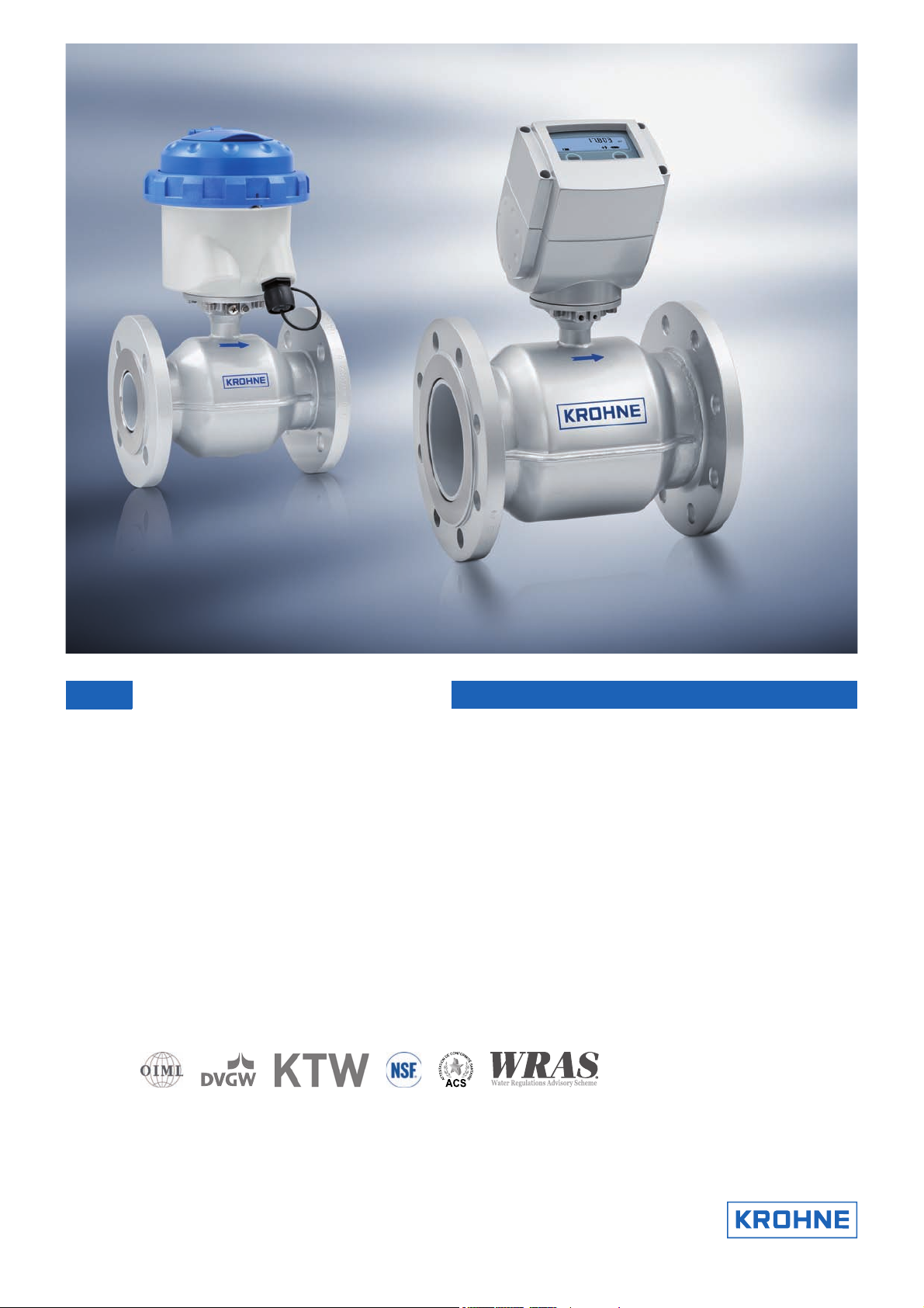
Battery powered electromagnetic water meter
• Battery driven with very low power consumption for remote locations
• Easy installation without straight inlet or outlet lengths
• IP68 rated signal converter for submersion in flooded chambers
© KROHNE 06/2013 - 4000663107 - TD WATERFLUX 3070 R07 en
Page 2

CONTENTS
WATERFLUX 3070
1 Product features 4
1.1 The power of independence ............................................................................................. 4
1.2 Options.............................................................................................................................. 6
1.3 Measuring principle.......................................................................................................... 9
2 Technical data 10
2.1 Technical data................................................................................................................. 10
2.2 Legal metrology.............................................................................................................. 16
2.2.1 OIML R49 ............................................................................................................................... 16
2.2.2 MID Annex MI-001................................................................................................................. 18
2.2.3 Verification to MI-001 & OIML R49 ....................................................................................... 20
2.3 Measurement accuracy.................................................................................................. 21
2.3.1 WATERFLUX 3070 without straight inlet and outlet sections .............................................. 22
2.4 Dimensions and weights ................................................................................................ 23
2.5 Pressure loss.................................................................................................................. 25
2.6 Battery lifetime............................................................................................................... 26
3 Installation 27
3.1 General notes on installation ......................................................................................... 27
3.2 Intended use ................................................................................................................... 27
3.3 Pre-installation requirements ....................................................................................... 27
3.4 General requirements .................................................................................................... 28
3.4.1 Vibration ................................................................................................................................ 28
3.4.2 Magnetic field........................................................................................................................ 28
3.5 Installation conditions ....................................................................................................29
3.5.1 Inlet and outlet...................................................................................................................... 29
3.5.2 T-section ............................................................................................................................... 29
3.5.3 Bends .................................................................................................................................... 30
3.5.4 Open discharge .....................................................................................................................30
3.5.5 Pump ..................................................................................................................................... 31
3.5.6 Control valve ......................................................................................................................... 31
3.5.7 Air venting and vacuum forces ............................................................................................. 31
3.5.8 Mounting position and flange deviation................................................................................ 32
3.5.9 IP68........................................................................................................................................ 33
3.6 Mounting......................................................................................................................... 34
3.6.1 Torques and pressures......................................................................................................... 34
3.7 Mounting of the signal converter ................................................................................... 37
3.7.1 IP67 housing, remote version............................................................................................... 37
3.7.2 IP68 housing, compact version............................................................................................. 37
4 Electrical connections 38
4.1 Safety instructions.......................................................................................................... 38
4.2 Grounding ....................................................................................................................... 38
4.3 Connection of the signal cable ....................................................................................... 39
4.3.1 IP 67 housing (field version).................................................................................................. 39
4.4 Connection of the output cable ...................................................................................... 41
2
www.krohne.com 06/2013 - 4000663107 - TD WATERFLUX 3070 R07 en
Page 3

WATERFLUX 3070
4.4.1 IP67 housing (compact and field version)............................................................................. 41
4.4.2 IP68 housing (compact version)............................................................................................ 42
CONTENTS
5 Notes 43
www.krohne.com06/2013 - 4000663107 - TD WATERFLUX 3070 R07 en
3
Page 4
1 PRODUCT FEATURES
1.1 The power of independence
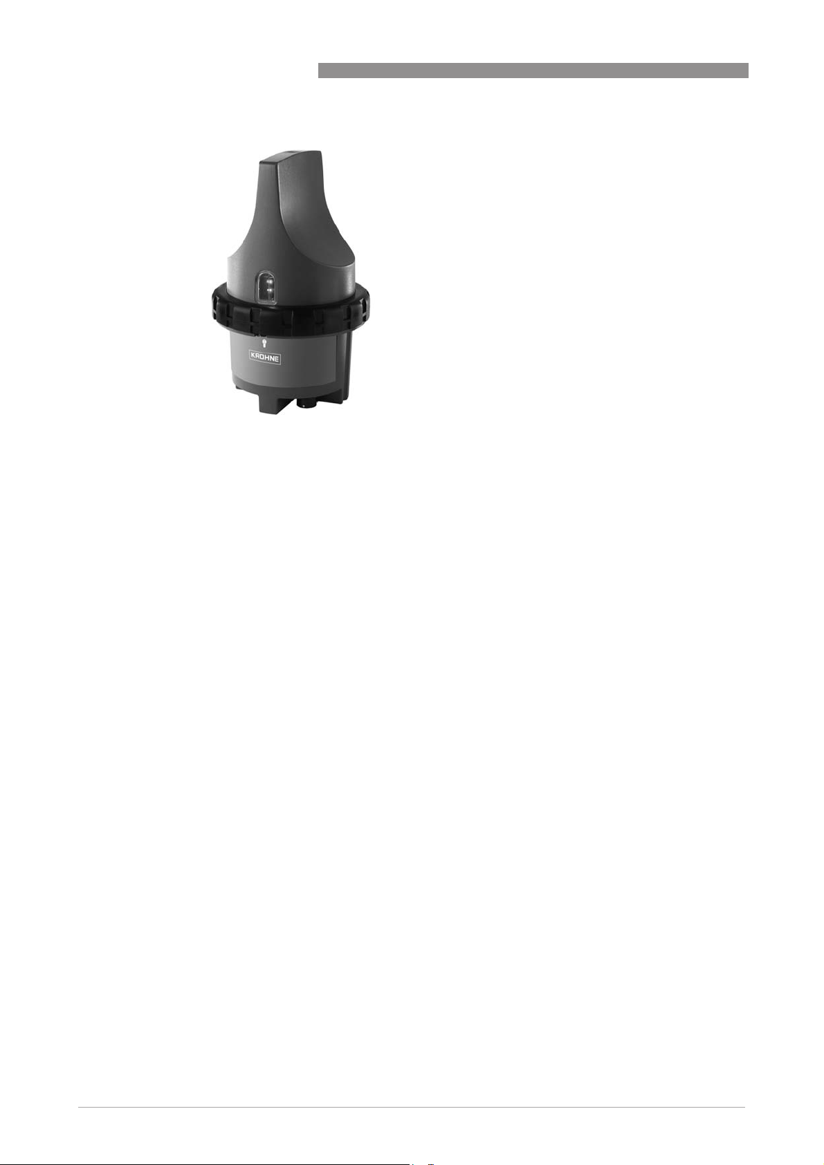
The IFC 070 is a battery powered electromagnetic signal converter designed for use in
combination with the WATERFLUX 3000 sensor. It is ideal for remote locations in the water
industry where no power connection is available and provides certainty in case of power failure.
The strengths of the WATERFLUX 3070 lies in its unique flow sensor construction with a
rectangular and reduced cross section and its efficient coil construction. The coils provide a
stronger and more homogenous magnetic field, leading to an improved signal to noise ratio. The
measurement is therefore independent of the flow profile and measurements are very stable.
This results in a very good low flow performance.
Because of the unique WATERFLUX flow sensor design, whereby the mean flow velocity and flow
profile are optimised within the rectangular and reduced cross section, the additional
uncertainty for upstream disturbances is drastically reduced. The water meter can be installed
directly behind an elbow or reducer in the pipe without straight inlet or outlet lengths.
A substantial reduction of inlet and outlet sections means smaller measurement pits.
Another major benefit of the rectangular sensor construction is the very low power consumption
of the signal converter. It has a long battery lifetime up to 15 years with two internal batteries
and 20 years with an external battery pack.
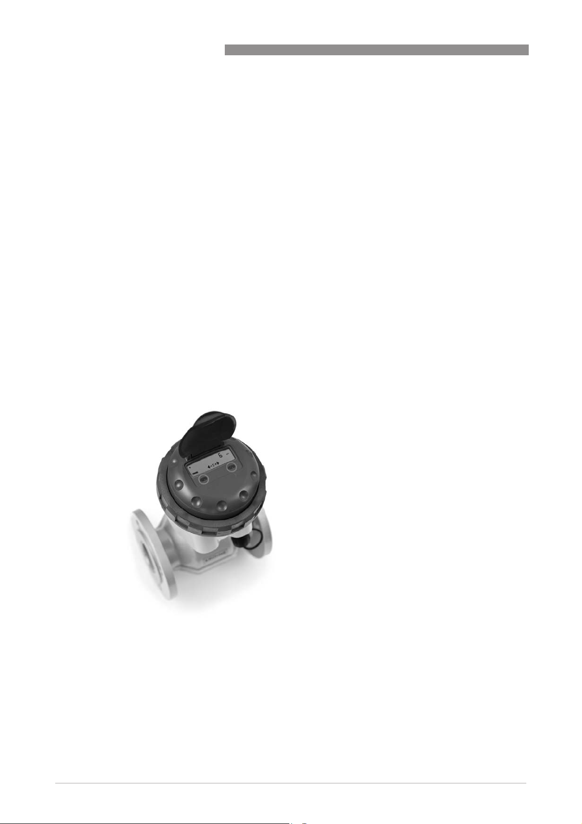
WATERFLUX 3070
1 LCD Display
2 Two optical keys to operate the converter without opening the housing
3 Battery powered signal converter
4
www.krohne.com 06/2013 - 4000663107 - TD WATERFLUX 3070 R07 en
Page 5

WATERFLUX 3070
Highlights
• Stand alone water meter with battery lifetime up to 15 years
• Unique rectangular sensor construction results in good low flow performance and
a large turndown ratio
• Large measuring range. High accuracy at peak flows during the day and
at low flows during the night
• Compliant with requirements for custody transfer (MID MI-001, OIML R49, ISO 4060, EN
14154)
• Standard inhouse wet calibration
• Optional verification to MID Annex MI-001 for water meters (Module B and D)
• No inlet or outlet sections required behind elbows or reducers
(MID / OIML R49 certified)
• Bi-directional flow metering
• Suitable for subsoil installation and constant flooding (IP68)
• Special coating for subsurface installation
• No need for measurement chambers
• Rilsan
• Drinking water approvals including ACS, DVGW, NSF, TZW and WRAS
• Reference electrode. No grounding rings needed
• Long term reliability and maintenance free.
No moving parts, no wear and no obstruction in the flow
• Optional KGA 42 external datalogger and GSM module for remote data transfer
®
polymer coating
PRODUCT FEATURES 1
Industries
• Water abstraction
• Distribution networks
• District metering
• Revenue metering
• Irrigation
• Dewatering
Applications
• Measurement of potable water, raw water and irrigation water
• Checking of pumps and water wells
• Monitoring of distribution networks
• Pipeline leak detection
• Water consumption and billing
www.krohne.com06/2013 - 4000663107 - TD WATERFLUX 3070 R07 en
5
Page 6
1 PRODUCT FEATURES
1.2 Options
WATERFLUX 3070
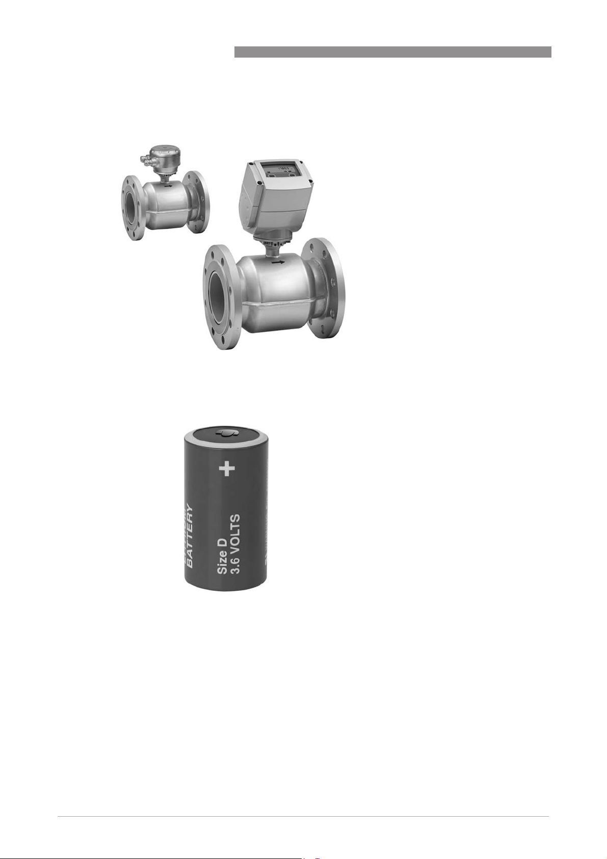
Remote or compact version
Remote or compact version
Remote or compact versionRemote or compact version
The WATERFLUX 3070 is available in a
compact or a remote (field) version. The
remote version of the signal converter
can be installed on a wall or on a pipe.
The functionality of the compact and the
remote version is identical.
Internal and external battery pack
Internal and external battery pack
Internal and external battery packInternal and external battery pack
The WATERFLUX 3070 can be operated
using 1 or 2 lithium monocell batteries
or an external battery pack. The meter
reading is saved internally, which
ensures that there is no loss of data
when changing the batteries.
The signal converter has a very low
power consumption because of its
rectangular sensor construction.
With two internal batteries it has a
battery lifetime up to 15 years.
6
www.krohne.com 06/2013 - 4000663107 - TD WATERFLUX 3070 R07 en
Page 7
WATERFLUX 3070
PRODUCT FEATURES 1
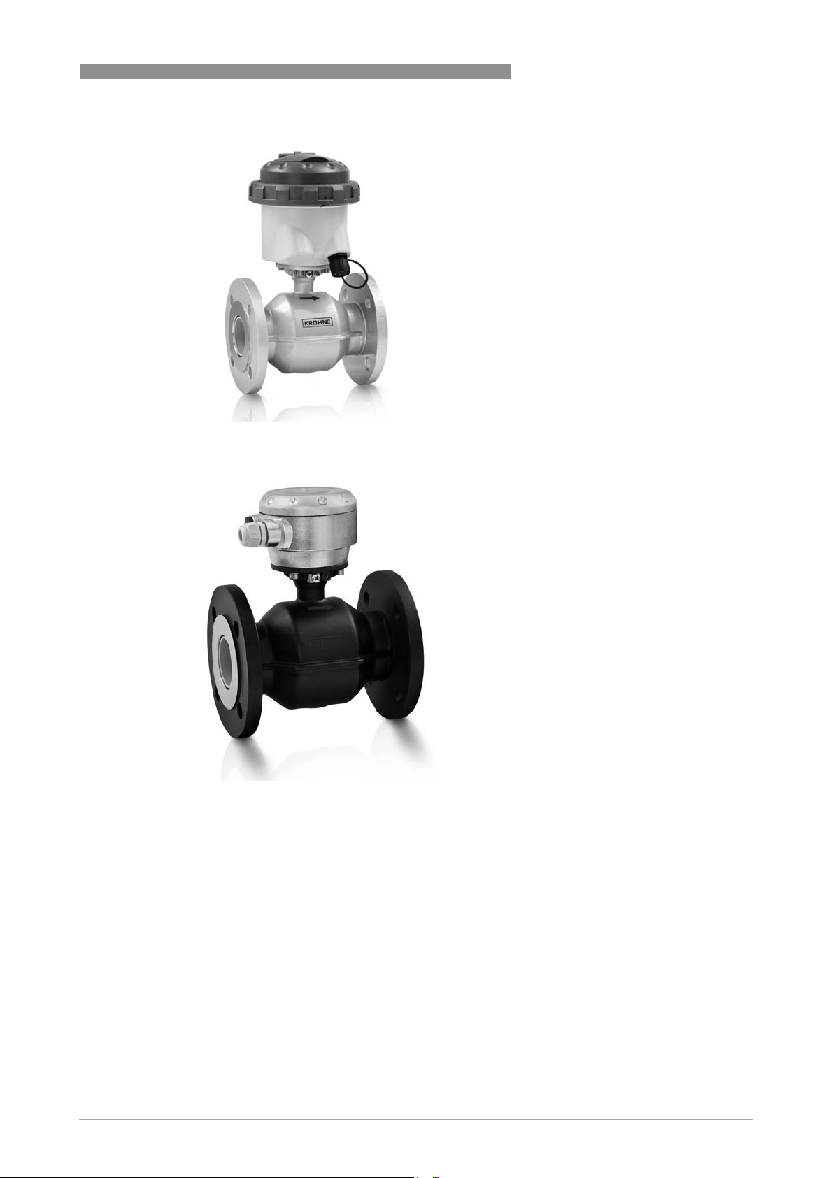
IP68 (NEMA 6P) version for submersion
IP68 (NEMA 6P) version for submersion
IP68 (NEMA 6P) version for submersionIP68 (NEMA 6P) version for submersion
The IFC 070 compact signal converter is
available in an aluminium and in a
polycarbonate housing.
The signal converter in a polycarbonate
housing is suitable for submersion in
flooded measurement chambers and is
protected to IP68 / NEMA 6P. The
output cable has plug and play IP68
rated connectors.
Maintenance free and buriable
Maintenance free and buriable
Maintenance free and buriable Maintenance free and buriable
The flow sensor (IP68) is suitable for
submersion in flooded measurement
chambers. With its robust construction
it can also be buried underground. This
can be a major cost saving as it
eliminates the need for a measurement
chamber. To protect the flow sensor a
special coating can be ordered as an
option. The remote version has an IP68
stainless steel connection box.
www.krohne.com06/2013 - 4000663107 - TD WATERFLUX 3070 R07 en
7
Page 8
1 PRODUCT FEATURES
WATERFLUX 3070
KGA 42 data logger and GSM module
KGA 42 data logger and GSM module
KGA 42 data logger and GSM module KGA 42 data logger and GSM module
for remote reading
for remote reading
for remote reading for remote reading
The KGA 42 data logger and GSM
module offers an efficient solution for
remote reading of water meters and the
transmission of data via wireless
communication. The KGA 42 sends out
SMS/GPRS reports on a daily basis or
di rect SMS/G PRS al erts t o mai nten ance
personnel. The module is easy to
install, waterproof (IP68), has a built-in
dedicated antenna and operates on
batteries.
It is ideal for water meters at remote
locations in the drinking water
distribution networks or sites difficult
to reach such as metering manholes
below the ground
8
www.krohne.com 06/2013 - 4000663107 - TD WATERFLUX 3070 R07 en
Page 9
WATERFLUX 3070
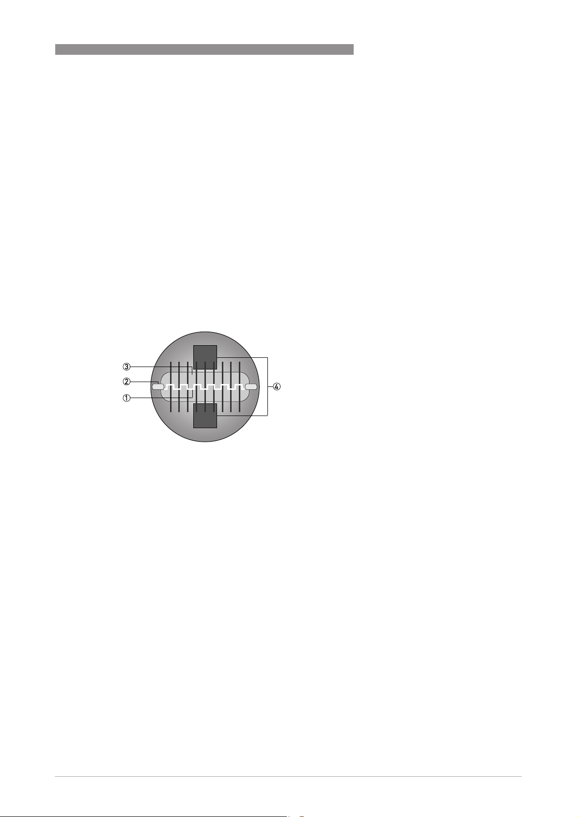
1.3 Measuring principle
An electrically conductive fluid flows inside an electrically insulated pipe through a magnetic
field. This magnetic field is generated by a current, flowing through a pair of field coils.
Inside of the fluid, a voltage U is generated:
U = v * k * B * D
U = v * k * B * D
U = v * k * B * DU = v * k * B * D
in which:
v = mean flow velocity
k = factor correcting for geometry
B = magnetic field strength
D = inner diameter of flow meter
The signal voltage U is picked off by electrodes and is proportional to the mean flow velocity v
and thus the flow rate q. A signal converter is used to amplify the signal voltage, filter it and
convert it into signals for totalising, recording and output processing.
PRODUCT FEATURES 1
1 Induced voltage (proportional to flow velocity)
2 Electrodes
3 Magnetic field
4 Field coils
Rectangular cross section
Rectangular cross section
Rectangular cross sectionRectangular cross section
The minimal height of the measuring tube decreases the distance between the field coils (4),
resulting in a stronger and more homogeneous magnetic field (3). In addition, the mean flow
velocity v increases due to the rectangular and reduced cross section. The large electrode
spacing (D) and the increased flow velocity results in a higher magnetic signal voltage, also in
the presence of a low flow rate.
www.krohne.com06/2013 - 4000663107 - TD WATERFLUX 3070 R07 en
9
Page 10
2 TECHNICAL DATA
2.1 Technical data
•
The following data is provided for general applications. If you require data that is more
relevant to your specific application, please contact us or your local sales office.
•
Additional information (certificates, special tools, software,...) and complete product
documentation can be downloaded free of charge from the website (Download Center).
Measuring system
Measuring principle Faraday's law of induction
Application range Electrically conductive fluids
Measured value
Measured value
Measured valueMeasured value
Primary measured value Flow velocity
Secondary measured value Volume flow
Design
Features Unique rectangular flow tube design providing improved flow profile and
WATERFLUX 3070
signal to noise ratio resulting in highest accuracy, low energy consumption
and large turndown ratio
Rilsan® polymer coated flow tube approved for drinking water
No internal or moving parts
Built-in reference electrode
Self providing energy by batteries for up to 15 years
Modular construction The measurement system consists of a flow sensor and a signal converter.
Compact version With IFC 070 converter: WATERFLUX 3070 C
Remote version In field (F) version with IFC 070 converter: WATERFLUX 3070 F
Nominal diameter DN25...600 / 1...24", Rectangular bore
Display and user interface
Display and user interface
Display and user interfaceDisplay and user interface
Display LCD display, 8 digits
Operation 2 optical keys to navigate through the menu of the signal converter without
Display information Standard:
Remote reading Optional: KGA 42 external data logger / GSM module
It is available as compact and as separate version.
Cable length up to 25 m / 75 ft
opening the housing.
Standard:
Standard:Standard:
Sum counter (default), forward counter, reverse counter or flow rate
Flow direction (forward or reverse), counter settings
Measured value
Measuring unit
Battery lifetime indicator
Optional:
Optional:
Optional:Optional:
Empty pipe, self test, display test, test mode, diameter, meter constant,
software version, AMR mode, warning sign, multiplier
10
www.krohne.com 06/2013 - 4000663107 - TD WATERFLUX 3070 R07 en
Page 11
WATERFLUX 3070
Measurements
Measuring units Volume
Measurement interval Default setting: 15s
Empty pipe detection Optional: display shows - EP - in case of empty pipe detection
Low flow cut off Measurements below this value are neglected
Measuring accuracy
Reference conditions Medium: water
Maximum measuring error DN25...300; down to 0.2% of the measured value ± 0.5 mm/s
Repeatability DN 25...300; ±0.1% (v >0.5 m/s / 1.5 ft/s)
Calibration / Verification Standard:
MID MI-001
(Directive 2004/22/EC)
TECHNICAL DATA 2
Volume
VolumeVolume
Default setting: m
Selectable: litre, gallon, imperial gallons, cubic feet, acre inch, acre feet
Flow rate
Flow rate
Flow rateFlow rate
Default setting: m3 / hr
Selectable: litre/sec, gallon/min, imperial gallon/min,
cubic feet/hour, acre inch/day, acre feet/day
Selectable: 1s, 5s, 10s, 15s, 20s
Default setting: 10 mm/s
Selectable: 0 mm/s, 5 mm/s, 10 mm/s
Temperature: +10...30°C / +50...86°F
Operating pressure: 1 bar / 14,5 psi
Inlet section: 3 DN / Outlet section: 1 DN
Electrical conductivity: > 300 µS/cm
DN350...600; down to 0.4% of the measured value ± 1 mm/s
The maximum measuring error depends on the installation conditions.
For detailed information refer to
DN350...600; ±0.2% (v >0.5 m/s / 1.5 ft/s)
Standard:
Standard:Standard:
2 Point calibration by a direct volume comparison.
Optional:
Optional: for DN25...300
Optional: Optional:
Verification to Measurement Instrument Directive (MID), Annex MI-001.
Standard: Verification at Ratio (Q3/Q1) = 80
Optional: Verification at Ratio (Q3/Q1) > 80
EC-Type examination certificate to MID Annex MI-001
EC-Type examination certificate to MID Annex MI-001
EC-Type examination certificate to MID Annex MI-001EC-Type examination certificate to MID Annex MI-001
Diameter: DN25...300
Minimum straight inlet flow: 0 DN
Minimum straight outlet flow: 0 DN
Forward and reverse (bi-directional) flow
Orientation: any
Ratio (Q3/Q1): up to 400
Liquid temperature range: +0.1°C / 50°C
Maximum operating pressure: ≤ DN200: 16 bar, ≥ DN250: 10 bar
For detailed information refer to
3
Measurement accuracy
Legal metrology
on page 21.
on page 16.
www.krohne.com06/2013 - 4000663107 - TD WATERFLUX 3070 R07 en
11
Page 12
2 TECHNICAL DATA
WATERFLUX 3070
OIML R49 Certificate of conformity to OIML R49
Certificate of conformity to OIML R49
Certificate of conformity to OIML R49Certificate of conformity to OIML R49
Diameter: DN25...300
Accuracy: Class 1 and 2
Minimum straight inlet flow: 0 DN
Minimum straight outlet flow: 0 DN
Forward and reverse (bi-directional) flow
Orientation: any
Ratio (Q3/Q1): up to 400
Liquid temperature range: +0.1°C / 50°C
Maximum operating pressure: ≤ DN200: 16 bar, ≥ DN250: 10 bar
For detailed information refer to
Legal metrology
Operating conditions
Temperature
Temperature
TemperatureTemperature
Process temperature -5...+70°C / +23...+158°F
Ambient temperature -40…+65°C / -40…+149°F
Ambient temperatures below -25°C / -13°F may affect the readability of the
display.
It is recommended to protect the converter from external heat sources
such as direct sunlight because high temperatures reduce the lifecycle of
all electronic components.
Storage temperature -50…+70°C / -58…+158°F
Measurement range
Measurement range -12...12 m/s / -40...40 ft/s
Measurement rangeMeasurement range
Starting flow From 0 m/s / 0 ft/s onwards
Pressure
Pressure
PressurePressure
Operating pressure Up to 16 bar (232 psi) for DN25...300
Vacuum load 0 mbar / 0 psi absolute
Pressure loss For detailed information refer to
Chemical properties
Chemical properties
Chemical propertiesChemical properties
Physical conditions Water: drinking water, raw water, irrigation water.
Electrical conductivity ≥ 20 μS/cm
Up to 10 bar (145 psi) for DN350...600
Pressure loss
For salt water, please contact the factory.
on page 16.
on page 25.
12
www.krohne.com 06/2013 - 4000663107 - TD WATERFLUX 3070 R07 en
Page 13
WATERFLUX 3070
Installation conditions
Installation Assure that flow sensor is always fully filled.
Flow direction Forward and reverse
Inlet run DN25...300 ≥ 0 DN
Outlet run DN25...300 ≥ 0 DN
Dimensions and weights For detailed information refer to
Materials
Sensor housing Sheet steel
Measuring tube DN25...200: metallic alloy
Flanges Steel 1.0460 / 1.0038 (RSt37-2)
Liner
Protective coating On exterior of the meter: flanges, housing, signal converter (compact
Measuring electrodes Standard: stainless steel 1.4301 / AISI 304
TECHNICAL DATA 2
For detailed information refer to
Arrow on flow sensor indicates forward flow direction.
DN350...600 ≥ 3 DN
For detailed information refer to
DN350...600 ≥ 1 DN
For detailed information refer to
DN250....600: stainless steel
DN25...DN200; Wetted parts nickel plated
®
Rilsan
version) and / or connection box (field version)
Standard: polyurethane coating
Option: subsoil coating
Installation
on page 27.
Measurement accuracy
Measurement accuracy
Dimensions and weights
on page 21.
on page 21.
on page 23.
Optional: Hastelloy® C
Reference electrode Standard: stainless steel 1.4301 / AISI 304
Optional: Hastelloy® C
Grounding rings Grounding rings can be omitted when the reference electrode is used.
Signal converter housing Standard:
Connection box Only for remote versions.
Standard:
Standard:Standard:
Aluminium with a polyester topcoat
Optional:
Optional:
Optional:Optional:
Polycarbonate (IP68)
Stainless steel (IP68)
Process connections
EN 1092-1 Standard:
ASME 1...12": 150 lb RF (232 psi / 16 bar rated)
Standard:
Standard:Standard:
DN25...200: PN 16
DN250...600 : PN 10
Optional:
Optional:
Optional:Optional:
DN250...600: PN16 ( DN350...600: 10 bar rated)
14...24": 150 lb (145 psi / 10 bar rated)
www.krohne.com06/2013 - 4000663107 - TD WATERFLUX 3070 R07 en
13
Page 14
2 TECHNICAL DATA
WATERFLUX 3070
JIS DN25...300 / 1...12": 10 K
AS 4087 DN25...600 / 1"...24" : Class 16 on request
AS 2129 DN25...600 / 1"...24": Table D, E on request
Other connections
Other connections
Other connectionsOther connections
Thread DN25: G1" thread connection on request
Other Weld-on, clamp, oval flanges: on request
DN350...600 / 14"...24": 7,5 K
(DN350...600 / 14"...24": 10 bar rated)
(DN350...600 / 14"...24": 10 bar rated)
For detailed information on nominal flange pressure and nominal diameter
refer to
DN40: G1.5" & G2" thread connection on request
Dimensions and weights
on page 23.
Electrical connections
Cable connections
Cable connections
Cable connectionsCable connections
Cable entries IFC 070 C and F in aluminium housing (IP67)
Output cable IFC 070 C in polycarbonate housing (IP68)
Power supply
Power supply
Power supplyPower supply
Battery Standard:
Typical lifetime
(default settings)
Alarms Pre-alarm at < 10% of its original capacity
Battery replacement No loss of totalizer data
IFC 070 C and F in aluminium housing (IP67)
IFC 070 C and F in aluminium housing (IP67)IFC 070 C and F in aluminium housing (IP67)
Standard: 2 x M20 x 1.45
Optional: 1/2" NPT, PF1/2
IFC 070 C in polycarbonate housing (IP68)
IFC 070 C in polycarbonate housing (IP68)IFC 070 C in polycarbonate housing (IP68)
Standard: No output connector. Pulse output not available.
Note: output connector can not be added afterwards.
Optional: Pulse output activated.
Output cable with plug and play - IP68 rated connector
Standard:
Standard:Standard:
Internal battery pack: Single D-cell (Lithium, 3.6V, 19 Ah)
Optional:
Optional:
Optional:Optional:
Internal battery pack: Dual D-cell (Lithium, 3.6V, 38 Ah)
External battery pack: Dual DD-cell (Lithium, 3.6V, 76 Ah),
IP68 rated. Cable length is 1.5 m
With 1 internal battery;
DN25...200 : up to 8 years
DN250...600 : up to 4 years
With 2 internal batteries;
DN25...200 : up to 15 years
DN250...600 : up to 8 years
With external battery pack;
DN25...200 : up to 20 years
DN250...600 : up to 15 years
For detailed information refer to
Final alarm at < 1% of its original capacity
Battery lifetime
on page 26.
14
www.krohne.com 06/2013 - 4000663107 - TD WATERFLUX 3070 R07 en
Page 15

WATERFLUX 3070
Signal cable
Signal cable (remote versions only)
Signal cableSignal cable
Type KROHNE WSC cable
Length Standard: 5m
In- and output
In- and output
In- and outputIn- and output
Pulse output 2 Passive pulse outputs (maximum 3 outputs possible; see status output)
Status output 2 Passive status outputs (1 status output can be used as a third pulse
Communication Optional: KGA 42 external datalogger / GSM module
TECHNICAL DATA 2
Optional: 10m, 15m, 20m, 25m
f ≤ 100 Hz; I ≤ 10 mA; U: 2.7…24 VDC (P ≤ 100 mW)
Volume / pulse is programmable
Phase shift between pulse A and B (forward and reverse) selectable
Pulse width is selectable:
5 ms (default), 10 ms, 20 ms, 50 ms, 100ms, 200 ms
output)
I ≤ 10 mA; U: 2.7…24 VDC (P ≤ 100 mW)
Function (selectable): self check, battery pre warning, battery final
warning, empty pipe
For detailed information refer to the KGA 42 documentation.
Approvals and certificates
CE
CE
CECE
This device fulfils the statutory requirements of the EC directives. The
manufacturer certifies successful testing of the product by applying the CE
mark.
Electromagnetic
compatibility
Pressure Equipment
Directive
Other approvals and standards
Other approvals and standards
Other approvals and standardsOther approvals and standards
Custody transfer
( DN25...300)
Drinking water approvals ACS, DVGW W270, NSF / ANSI Standard 61, TZW, WRAS
Protection category acc. to
IEC 529 / EN 60529
Shock test IEC 68-2-27
Vibration test IEC 68-2-64
Directive: 2004/108/EC
Harmonized standard: EN 61326-1: 2006
Not applicable: networks for the supply, distribution and discharge of
water and associated equipment are excluded from the scope of this
directive.
MID Annex MI-001 type examination certificate
OIML R49 certificate of conformity
Conformity with ISO 4064 and EN 14541
Innerstaatliche Bauartzulassung als Kaeltezaehler (For Germany,
Switserland and Austria).
DN40...100; SANS 1529 (South Africa)
Compact version (C) in polycarbonate housing: IP68 (NEMA 4X/6P)
(Test conditions; 1500 hours, 10 meters below surface)
Compact version (C) in aluminium housing: IP66/67 (NEMA 4/4X/6)
Field version (F) in aluminium housing: IP66/67 (NEMA 4/4X/6)
30 g for 18 ms
f = 20 - 20000 Hz, rms = 4.5g, t = 30 min.
www.krohne.com06/2013 - 4000663107 - TD WATERFLUX 3070 R07 en
15
Page 16

2 TECHNICAL DATA
2.2 Legal metrology
2.2.1 OIML R49
The WATERFLUX 3070 has a certificate of conformity with the international recommendation
OIML R49. The certificate has been issued by NMi.
The OIML R49 recommendation (2006) concerns water meters intended for the metering of cold
potable and hot water. The measuring range of the water meter is determined by Q3 (nominal
flow rate) and R (ratio).
The WATERFLUX 3070 meets the requirements for water meters
of accuracy class 1 and 2.
• For accuracy class 1, the maximum permissible error for water meters is ±1% for the upper
flow rate zone and ±3% for the lower flow rate zones.
• For accuracy class 2, the maximum permissible error for water meters is ±2% for the upper
flow rate zone and ±5% for the lower flow rate zones.
According to OIML R49, accuracy class 1 designation shall be applied only to water meters with
3
Q3 ≥ 100 m
/h.
WATERFLUX 3070
Q1 = Q3 / R
Q2 = Q1 * 1.6
Q3 = Q1 * R
Q4 = Q3 * 1.25
Figure 2-1: ISO flow rates added to figure as comparison towards OIML
X: Flow rate; Y [%]: Maximum measuring error
1 Upper flow rate zone: ± 3% (class 1), ± 5% (class 2)
2 Lower flow rate zone: ± 1% (class 1), ±2% (class 2)
16
www.krohne.com 06/2013 - 4000663107 - TD WATERFLUX 3070 R07 en
Page 17

WATERFLUX 3070
OIML R49 Class 1; certified metrological characteristics
TECHNICAL DATA 2
DN Span (R)
Flow rate [m3/h]
Q3 / Q1
Minimum
TransitionalQ2Permanent
Q1
65 250 0.400 0.640 100 125.0
80 160 0.625 1.000 100 125.0
80 250 0.640 1.024 160 200.0
100 160 1.000 1.600 160 200.0
100 250 1.000 1.600 250 312.5
125 160 1.563 2.500 250 312.5
125 250 1.600 2.560 400 500.0
150 160 2.500 4.000 400 500.0
150 250 2.520 4.032 630 787.5
200 160 3.938 6.300 630 787.5
200 200 4.000 6.400 800 1000.0
250 160 6.250 10.000 1000 1250.0
300 160 10.000 16.000 1600 2000.0
OIML R49 Class 2; certified metrological characteristics
DN Span (R)
Q3 /Q1
Minimum
Q1
Flow rate [m3/h]
TransitionalQ2Permanent
Q3
Q3
Overload
Q4
Overload
Q4
25 400 0.025 0.040 10 12.5
25 400 0.040 0.064 16 20.0
40 400 0.063 0.100 25 31.3
40 400 0.100 0.160 40 50.0
50 400 0.100 0.160 40 50.0
50 400 0.160 0.252 63 78.8
65 400 0.160 0.250 63 78.8
65 400 0.250 0.400 100 125.0
80 400 0.250 0.400 100 125.0
80 400 0.400 0.640 160 200.0
100 400 0.400 0.640 160 200.0
100 400 0.625 1.000 250 312.5
125 400 0.625 1.000 250 312.5
125 400 1.000 1.600 400 500.0
150 400 1.000 1.600 400 500.0
150 400 1.575 2.520 630 787.5
200 400 1.575 2.520 630 787.5
250 400 2.500 4.000 1000 1250.0
300 400 4.000 6.400 1600 2000.0
www.krohne.com06/2013 - 4000663107 - TD WATERFLUX 3070 R07 en
17
Page 18

2 TECHNICAL DATA
2.2.2 MID Annex MI-001
All new designs of water meters that are to be used for legal purposes in Europe require
certification under the Measurement Instrument Directive (MID) 2004/22/EC.
Annex MI-001 of the MID applies to water meters intended for the measurement of volume of
clean, cold or heated water in residential, commercial, and light industrial use. An EC-type
examination certificate is valid in all countries of the European Union.
The WATERFLUX 3070 has an EC-type examination certificate and can be verified to the
MID Annex MI-001 for water meters with diameter DN25...DN300. The conformity assessment
procedure followed for the WATERFLUX 3070 is Module B (Type Examination) and Module D
(Quality Assurance of the Production Process).
The maximum permissible error on volumes delivered between Q2 (transitional) flow rate and
Q4 (overload) flow rate is ±2%.
The maximum permissible error on volumes delivered between Q1 (minimum) flow rate and Q2
(transitional) flow rate is ±5%.
Q1 = Q3 / R
Q2 = Q1 * 1.6
Q3 = Q1 * R
Q4 = Q3 * 1.25
WATERFLUX 3070
18
Figure 2-2: ISO flow rates added to figure as comparison towards MID
X:
X: Flow rate
X:X:
Y [%]:
Y [%]: Maximum measuring error
Y [%]:Y [%]:
www.krohne.com 06/2013 - 4000663107 - TD WATERFLUX 3070 R07 en
Page 19

WATERFLUX 3070
MI-001 certified flow characteristics
TECHNICAL DATA 2
DN Span (R)
Flow rate [m3/h]
Q3 / Q1
Minimum Q1 Transitional Q2 Permanent Q3 Overload Q4
25 400 0.025 0.040 10 12.5
25 400 0.040 0.064 16 20.0
40 400 0.063 0.100 25 31.3
40 400 0.100 0.160 40 50.0
50 400 0.100 0.160 40 50.0
50 400 0.158 0.252 63 78.8
65 400 0.158 0.252 63 78.8
65 400 0.250 0.400 100 125.0
80 400 0.250 0.400 100 125.0
80 400 0.400 0.640 160 200.0
100 400 0.400 0.640 160 200.0
100 400 0.625 1.000 250 312.5
125 400 0.625 1.000 250 312.5
125 400 1.000 1.600 400 500.0
150 400 1.000 1.600 400 500.0
150 400 1.575 2.520 630 787.5
200 400 1.575 2.520 630 787.5
200 315 2.540 4.060 800 1000.0
250 400 2.500 4.000 1000 1250.0
300 400 4.000 6.400 1600 2000.0
www.krohne.com06/2013 - 4000663107 - TD WATERFLUX 3070 R07 en
19
Page 20

2 TECHNICAL DATA
2.2.3 Verification to MI-001 & OIML R49
Verification to MI-001 and OIML R49, standard at the following values for R, Q1, Q2 and Q3.
Verification at other values for R and Q3 available on request.
Verification to MI-001
WATERFLUX 3070
DN Span (R)
Flow rate [m3/h]
Q1 Q2 Q3
25 80 0.050 0.080 4
32 80 0.125 0.200 10
40 80 0.125 0.200 10
50 80 0.200 0.320 16
65 80 0.313 0.500 25
80 80 0.500 0.800 40
100 80 0.788 1.260 63
125 80 1.250 2.000 100
150 80 2.000 3.200 160
200 80 3.125 5.000 250
250 80 5.000 8.000 400
300 80 7.875 12.600 630
20
www.krohne.com 06/2013 - 4000663107 - TD WATERFLUX 3070 R07 en
Page 21

WATERFLUX 3070
2.3 Measurement accuracy
Each water meter is standard wet calibrated under reference conditions by direct volume
comparison. The performance of the water meter is defined and documented in an individual
water meter calibration certificate.
Reference conditions
• Medium: water
• Temperature: +10...30°C / +50...86°F
• Pressure: 1 bar / 14.5 psi
• Inlet section: ≥ 3 DN
• Outlet section: ≥ 1 DN
• Electrical conductivity: ≥ 300 μS/cm
TECHNICAL DATA 2
Figure 2-3: Measuring accuracy
X [m/s]: Flow velocity; Y [%]: Maximum measuring error
Accuracy with IFC 070 converter
Inlet Outlet Accuracy Curve
DN25...300 / 1...12" 3 DN 1 DN 0.2% + 0.5 mm/s 1
DN350...600 / 14...24" 3 DN 1 DN 0.4% + 1 mm/s 2
www.krohne.com06/2013 - 4000663107 - TD WATERFLUX 3070 R07 en
21
Page 22

2 TECHNICAL DATA
2.3.1 WATERFLUX 3070 without straight inlet and outlet sections
Disturbed flow profiles, such as those that occur behind elbows, tee pieces, reducers or valves
installed in front of a water meter, affect the measuring performance. Therefore it is usually
recommended to fit a straight inlet length in front of and straight outlet length behind a water
meter.
As a result of the unique WATERFLUX flow sensor design, whereby the mean flow velocity and
flow profile are optimised within the rectangular and reduced cross section, the additional
uncertainty for upstream disturbances are drastically reduced. Therefore the requirements for
straight length and in front of and behind a meter are reduced.
The NMi has performed tests with various flow and swirl disturbers according to ISO 4064 and
EN 14154. Based on these results the WATERFLUX 3070 has received a
OIML R49 certificate
• Diameter range DN25...300
• Accuracy class 1 and class 2
• Minimum straight inlet and outlet pipe length of 0 DN
• Bi-directional flow
WATERFLUX 3070
EC-type certificate according MID Annex MI-001
• Diameter range DN25...300
• Minimum straight inlet and outlet pipe length of 0 DN
• Bi-directional flow
22
www.krohne.com 06/2013 - 4000663107 - TD WATERFLUX 3070 R07 en
Page 23

WATERFLUX 3070
2.4 Dimensions and weights
Remote flow sensor
Remote flow sensor a = 88 mm / 3.5"
Remote flow sensorRemote flow sensor
Remote version in
Remote version in
Remote version in Remote version in
aluminium housing
aluminium housing
aluminium housing aluminium housing
(IP67)
(IP67)
(IP67)(IP67)
TECHNICAL DATA 2
b = 139 mm / 5.5" 1
c = 106 mm / 4.2"
Total height = H + a
b = 132 mm / 5.2"
c = 235 mm / 9.3"
H = 310 mm / 12.2"
Weight = 3.3 kg / 7.3 lb
Compact version in
Compact version in
Compact version in Compact version in
aluminium housing
aluminium housing
aluminium housing aluminium housing
(IP67)
(IP67)
(IP67)(IP67)
Compact version in
Compact version in
Compact version in Compact version in
polycarbonate housing
polycarbonate housing
polycarbonate housing polycarbonate housing
(IP68)
(IP68)
(IP68)(IP68)
1 The value may vary depending on the used cable glands.
•
All data given in the following tables are based on standard versions of the flow sensor only.
•
Especially for smaller nominal sizes of the flow sensor, the signal converter can be bigger
a = 170 mm / 6.7"
b = 132 mm / 5.2"
c = 140 mm / 5.5"
Total height = H + a
a = 159 mm / 6.3"
b = 161 mm / 6.3"
Total height = H + a
than the flow sensor.
•
Note that for other pressure ratings than mentioned, the dimensions may be different.
•
For full information on signal converter dimensions see relevant documentation.
www.krohne.com06/2013 - 4000663107 - TD WATERFLUX 3070 R07 en
23
Page 24

2 TECHNICAL DATA
EN 1092-1
WATERFLUX 3070
Nominal size
DN [mm]
25 150 151 115 5
40 150 166 150 6
50 200 186 165 13
65 200 200 185 11
80 200 209 200 17
100 250 237 220 17
125 250 266 250 21
150 300 300 285 29
200 350 361 340 36
250 400 408 395 50
300 500 458 445 60
350 500 510 505 85
400 600 568 565 110
450 600 618 615 125
500 600 671 670 120
600 600 781 780 180
ASME B16.5 / 150 lb
Dimensions [mm] Approx. weight
[kg]
L H W
Nominal size
[inches]
Dimensions [inches] Approx. weight
[lb]
L H W
1 5.91 5.83 4.3 18
1½ 5.91 6 4.9 21
2 7.87 7.05 5.9 34
3 7.87 8.03 7.5 42
4 9.84 9.49 9.0 56
5 9.84 10.55 10.0 65
6 11.81 11.69 11.0 80
8 13.78 14.25 13.5 100
10 15.75 16.3 16.0 148
12 19.7 18.8 19.0 210
14 27.6 20.7 21 290
16 31.5 22.9 23.5 370
18 31.5 24.7 25 420
20 31.5 27 27.5 500
24 31.5 31.4 32 680
24
www.krohne.com 06/2013 - 4000663107 - TD WATERFLUX 3070 R07 en
Page 25

WATERFLUX 3070
2.5 Pressure loss
Figure 2-4: Pressure loss between 1 m/s and 9 m/s for DN25...100
1 DN25
2 DN40
3 DN50
4 DN65
5 DN80
6 DN100
TECHNICAL DATA 2
Figure 2-5: Pressure loss between 1 m/s and 9 m/s for DN125...300
1 DN125
2 DN150
3 DN200
4 DN250
5 DN300
Figure 2-6: Pressure loss between 1 m/s and 9 m/s for DN350...600
1 DN350
2 DN400
3 DN450
4 DN500
5 DN600
www.krohne.com06/2013 - 4000663107 - TD WATERFLUX 3070 R07 en
25
Page 26

2 TECHNICAL DATA
2.6 Battery lifetime
The maximum battery lifetime depends on the choice of battery pack, the diameter and the
measurement interval.
Other factors influencing the battery lifetime include the ambient temperature, the pulse output
settings, the status output, and the pulse width . The graphs show the battery lifetime for the
different available battery types and measurement intervals.
Conditions
The maximum battery lifetime is based on default menu settings, an ambient temperature of
25°C / 77°F and a flow rate at 2 m/s.
Maximum lifetime of batteries for: DN25...200
WATERFLUX 3070
Figure 2-7: XXXX = Measuring interval in seconds, YYYY = typical lifetime in years
Maximum lifetime of batteries for: DN250...600
Figure 2-8: XXXX = Measuring interval in seconds, YYYY = typical lifetime in years
1 Single D-cell battery
2 Dual D-cell battery
3 External battery
26
www.krohne.com 06/2013 - 4000663107 - TD WATERFLUX 3070 R07 en
Page 27

WATERFLUX 3070
3.1 General notes on installation
Inspect the cartons carefully for damages or signs of rough handling. Report damage to the
carrier and to the local office of the manufacturer.
Do a check of the packing list to make sure that you have all the elements given in the order.
Look at the device nameplate to ensure that the device is delivered according to your order.
Check for the correct supply voltage printed on the nameplate.
3.2 Intended use
Responsibility for the use of the measuring devices with regard to suitability, intended use and
corrosion resistance of the used materials against the measured fluid lies solely with the
operator.
The manufacturer is not liable for any damage resulting from improper use or use for other than
the intended purpose.
INSTALLATION 3
This flowmeter is designed exclusively to measure the flow of drinking water, raw water and
irrigation water.
If the device is not used according to the operating conditions (refer to chapter Technical data),
the intended protection could be affected.
3.3 Pre-installation requirements
Make sure that you have all necessary tools available:
• Allen key (4 mm)
• Small screwdriver
• Wrench for cable glands
• Wrench for wall mounting bracket (remote version only)
• Torque wrench for installing flowmeter in pipeline
www.krohne.com06/2013 - 4000663107 - TD WATERFLUX 3070 R07 en
27
Page 28

3 INSTALLATION
3.4 General requirements
The following precautions must be taken to ensure reliable installation.
•
Make sure that there is adequate space to the sides.
•
Protect the signal converter from direct sunlight and install a sun shade if necessary.
•
Signal converters installed in control cabinets require adequate cooling, e.g. by fan or heat
exchanger.
•
Do not expose the signal converter to intense vibration. The flowmeters are tested for a
vibration level in accordance with IEC 68-2-64.
3.4.1 Vibration
WATERFLUX 3070
Figure 3-1: Avoid vibrations
3.4.2 Magnetic field
Figure 3-2: Avoid magnetic fields
28
www.krohne.com 06/2013 - 4000663107 - TD WATERFLUX 3070 R07 en
Page 29

WATERFLUX 3070
3.5 Installation conditions
3.5.1 Inlet and outlet
DN25...300
Figure 3-3: Minimal inlet and outlet
1 Inlet: ≥ 0 DN
2 Outlet: ≥ 0 DN
INSTALLATION 3
DN350...600
Figure 3-4: Minimal inlet and outlet
1 Inlet: ≥ 3 DN
2 Outlet: ≥ 1 DN
3.5.2 T-section
Figure 3-5: Distance behind a T-section
1 DN 25...300: ≥ 0 DN & DN 350...600: ≥ 3 DN
www.krohne.com06/2013 - 4000663107 - TD WATERFLUX 3070 R07 en
29
Page 30

3 INSTALLATION
3.5.3 Bends
Figure 3-6: Installation in bending pipes
WATERFLUX 3070
Figure 3-7: Installation in bending pipes
Avoid draining or partial filling of the flow sensor
3.5.4 Open discharge
Figure 3-8: Installation in front of an open discharge
30
www.krohne.com 06/2013 - 4000663107 - TD WATERFLUX 3070 R07 en
Page 31

WATERFLUX 3070
3.5.5 Pump
Figure 3-9: Recommended installation: behind a pump
1 Inlet: ≥ 3 DN
3.5.6 Control valve
INSTALLATION 3
Figure 3-10: Recommended installation: in front of a control valve
3.5.7 Air venting and vacuum forces
Figure 3-11: Air venting
1 ≥ 5 m
2 Air ventilation point
www.krohne.com06/2013 - 4000663107 - TD WATERFLUX 3070 R07 en
31
Page 32

3 INSTALLATION
Figure 3-12: Vacuum
1 ≥ 5 m
3.5.8 Mounting position and flange deviation
WATERFLUX 3070
32
Figure 3-13: Mounting position and flange deviation
1 L
max
2 L
min
• Mount flow sensor either with signal converter aligned upwards or downwards.
• Install flow sensor in line with the pipe axis.
• Pipe flange faces must be parallel to each other.
Max. permissible deviation of pipe flange faces: L
www.krohne.com 06/2013 - 4000663107 - TD WATERFLUX 3070 R07 en
max
- L
≤ 0.5 mm / 0.02".
min
Page 33

WATERFLUX 3070
3.5.9 IP68
The WATERFLUX 3000 flow sensor is rated IP68 (NEMA 4X/6P). It is suitable for submersion in
flooded measurement chambers and for subsurface installation.
The compact IFC 070 signal converter is available in:
• an aluminium housing suitable for IP66/67, NEMA 4/4X/6
• a polycarbonate housing suitable for IP68, NEMA 4/4X/6.
The remote IFC 070 signal converter is available in:
• an aluminium housing suitable for IP66/67, NEMA 4/4X/6.
INSTALLATION 3
This version is suitable for periodic submersion in flooded measurement chambers. The
output cable has IP68 rated (military) connectors.
In case of continuous or long term submersion it is advised to select the field (remote)
version (IP66/67). Submersion under water is possible down to a depth of 5 meters.
Figure 3-14: IP68 versions
1 Submersible
2 Buried
12
www.krohne.com06/2013 - 4000663107 - TD WATERFLUX 3070 R07 en
33
Page 34

3 INSTALLATION
3.6 Mounting
3.6.1 Torques and pressures
The maximum pressure and torques values for the flowmeter are theoretical and calculated for
optimum conditions and use with carbon steel flanges.
WATERFLUX 3070
Figure 3-15: Tightening of bolts
Tightening of bolts
• Always tighten the bolts uniformely and in diagonally opposite sequence.
• Do not exceed the maximum torque value.
• Step 1: Apply approx. 50% of max. torque given in table.
• Step 2: Apply approx. 80% of max. torque given in table.
• Step 3: Apply 100% of max. torque given in table.
34
www.krohne.com 06/2013 - 4000663107 - TD WATERFLUX 3070 R07 en
Page 35

WATERFLUX 3070
INSTALLATION 3
Nominal size
DN [mm]
25 PN 16 4 x M 12 12
40 PN 16 4 × M 16 30
50 PN 16 4 × M 16 36
65 PN 16 8 × M 16 50
80 PN 16 8 × M 16 30
100 PN 16 8 × M 16 32
125 PN 16 8 × M 16 40
150 PN 10 8 x M 20 55
150 PN 16 8 × M 20 55
200 PN 10 8 × M 20 85
200 PN 16 12 x M 20 57
250 PN 10 12 x M 20 80
250 PN 16 12 x M 24 100
300 PN 10 12 x M 20 95
300 PN 16 12 x M 24 136
350 PN 10 16 x M 20 96
400 PN 10 16 x M 24 130
450 PN 10 20 x M 24 116
500 PN 10 20 x M 24 134
600 PN 10 20 x M 27 173
1 Th e to rqu e va lue s al so d epe nd o n variables (temperature, bolt material, gasket material, lubricants, etc.)
outside the control of the manufacturer. Therefore these values should be regarded as indicative only.
Pressure
r a t i n g
Bolts Max. torque
1
[Nm]
www.krohne.com06/2013 - 4000663107 - TD WATERFLUX 3070 R07 en
35
Page 36

3 INSTALLATION
WATERFLUX 3070
Nominal size
[inches]
1 150 4 x 1/2" 4
1½ 150 4 x 1/2" 11
2 150 4 × 5/8" 18
2.5 150 8 x 5/8" 27
3 150 4 × 5/8" 33
4 150 8 × 5/8" 22
5 150 8 × 3/4" 33
6 150 8 × 3/4" 48
8 150 8 × 3/4" 66
10 150 12 x 7/8" 74
12 150 12 x 7/8" 106
14 150 2 12 × 1" 87
16 150 2 16 × 1" 84
18 150 2 16 × 1 1/8" 131
20 150 2 20 × 1 1/8" 118
24 150 2 20 × 1 1/4" 166
1 Th e to rqu e va lue s al so d epe nd o n variables (temperature, bolt material, gasket material, lubricants, etc.)
outside the control of themanufacturer. Therefore these values should be regarded as indicative only.
2 No full rating (max. 145 psi).
Flange class
[lb]
Bolts Max. torque
[lbs.ft]
1
36
www.krohne.com 06/2013 - 4000663107 - TD WATERFLUX 3070 R07 en
Page 37

WATERFLUX 3070
3.7 Mounting of the signal converter
Assembly materials and tools are not part of the delivery. Use the assembly materials and tools
in compliance with the applicable occupational health and safety directives.
3.7.1 IP67 housing, remote version
Pipe mounting
Pipe mounting
Pipe mountingPipe mounting
INSTALLATION 3
Figure 3-16: Pipe mounting of the field housing
1 Fix the signal converter to the pipe.
2 Fasten the signal converter using standard U-bolts and washers.
3 Tighten the nuts.
Wall mounting
Wall mounting
Wall mountingWall mounting
No special requirements.
3.7.2 IP68 housing, compact version
Figure 3-17: Closing of IP68 housing
• Before closing the case of the converter, ensure that all surfaces in contact with the seals are
clean.
• Position the upper part of the case and tighten the lock ring.
• Use the wrench to tighten the ring as shown.
www.krohne.com06/2013 - 4000663107 - TD WATERFLUX 3070 R07 en
37
Page 38

4 ELECTRICAL CONNECTIONS
4.1 Safety instructions
All work on the electrical connections may only be carried out with the power disconnected. Take
note of the voltage data on the nameplate!
Observe the national regulations for electrical installations!
Observe without fail the local occupational health and safety regulations. Any work done on the
electrical components of the measuring device may only be carried out by properly trained
specialists.
Look at the device nameplate to ensure that the device is delivered according to your order.
Check for the correct supply voltage printed on the nameplate.
4.2 Grounding
WATERFLUX 3070
Figure 4-1: Grounding
Grounding without grounding rings. The flow sensor is equipped with a reference electrode.
38
www.krohne.com 06/2013 - 4000663107 - TD WATERFLUX 3070 R07 en
Page 39

WATERFLUX 3070
4.3 Connection of the signal cable
4.3.1 IP 67 housing (field version)
To ensure smooth functioning, always use the signal cables included in the delivery.
The signal cable is only used for remote versions. The standard WSC-cable includes both
electrode and field current leads.
ELECTRICAL CONNECTIONS 4
Figure 4-2: Preparation of standard cable (both sides)
1 Shielding
2 Blue + green + yellow cable, used for field current (terminals 7, 8, 9)
3 Brown + white + violet cable, used for electrode signals (terminals 1, 2, 3)
4 Drain wires
Dimensions of cable
a b c d e f
mm 75 35 70 5 45 30
inch 3.0 1.4 2.8 0.2 1.8 1.2
Figure 4-3: Cable connection at sensor side, standard cable
1 Connect drain wires under screw
2 Connect shielding under clamp
www.krohne.com06/2013 - 4000663107 - TD WATERFLUX 3070 R07 en
39
Page 40

4 ELECTRICAL CONNECTIONS
Figure 4-4: Cable connection at converter side, standard cable
1 Connect drain wires under screw
2 Connect shielding under clamp
• Prepare appropriate cable lengths as shown.
• Connect the wires as shown in the following table.
WATERFLUX 3070
Wire color Terminal Function
Brown 1 Reference electrode
White 2 Standard electrode signal
Violet 3 Standard electrode signal
Blue 7 Field current
Green 8 Field current
Yellow 9 No function
Drain wires Screws Shielding
40
www.krohne.com 06/2013 - 4000663107 - TD WATERFLUX 3070 R07 en
Page 41

WATERFLUX 3070
4.4 Connection of the output cable
4.4.1 IP67 housing (compact and field version)
ELECTRICAL CONNECTIONS 4
Figure 4-5: Removing side cap
Figure 4-6: Terminal assignment
1 Status output 1 or pulse output C
2 Status output 2
3 Not used
4 Common ground
5 Pulse output A
6 Pulse output B
6
5
4
3
2
1
Electrical values
• Pulse output passive:
Pulse output passive:
Pulse output passive:Pulse output passive:
f ≤ 100 Hz; I ≤ 10 mA; U: 2.7...24 VDC (P ≤ 100 mW)
• Status output passive:
Status output passive:
Status output passive:Status output passive:
I ≤ 10 mA; U: 2.7...24 VDC (P ≤ 100 mW)
www.krohne.com06/2013 - 4000663107 - TD WATERFLUX 3070 R07 en
41
Page 42

4 ELECTRICAL CONNECTIONS
4.4.2 IP68 housing (compact version)
Figure 4-7: Output cable at IP68 compact version
1 Color coded leads of output cable
If an output is activated, the output cable with the IP68 rated connector has the following leads:
Output cable with IP68 rated connectors with 5 color coded leads:
WATERFLUX 3070
Wire color Contact on
Function
connector
Yellow A Status output 1
White G Status output 2
Blue H Ground
Brown B Pulse output A
Green F Pulse output B
Pink C External battery +
Grey E External battery -
Electrical values
• Pulse output passive:
Pulse output passive:
Pulse output passive:Pulse output passive:
f ≤ 100 Hz; I ≤ 10 mA; U: 2.7...24 VDC (P ≤ 100 mW)
• Status output passive:
Status output passive:
Status output passive:Status output passive:
I ≤ 10 mA; U: 2.7...24 VDC (P ≤ 100 mW)
42
www.krohne.com 06/2013 - 4000663107 - TD WATERFLUX 3070 R07 en
Page 43

WATERFLUX 3070
NOTES 5
www.krohne.com06/2013 - 4000663107 - TD WATERFLUX 3070 R07 en
43
Page 44

K
K
K
KROHNE product overview
• Electromagnetic flowmeters
• Variable area flowmeters
• Ultrasonic flowmeters
• Mass flowmeters
• Vortex flowmeters
• Flow controllers
• Level meters
• Temperature meters
• Pressure meters
• Analysis products
• Products and systems for the oil & gas industry
• Measuring systems for the marine industry
Head Office KROHNE Messtechnik GmbH
Ludwig-Krohne-Str. 5
47058 Duisburg (Germany)
Tel.:+49 (0)203 301 0
Fax:+49 (0)203 301 10389
info@krohne.de
The current list of all KROHNE contacts and addresses can be found at:
© KROHNE 06/2013 - 4000663107 - TD WATERFLUX 3070 R07 en - Subject to change without notice.
www.krohne.com
 Loading...