

Page 1
Quick Start
Quick Start
WATERFLUX 3070
WATERFLUX 3070
WATERFLUX 3070WATERFLUX 3070
Quick Start Quick Start
Battery powered electromagnetic water meter
Electronic Revision ER 4.3.0_ up to ER 4.3.4_
(SW.REV 4.2.2_ up to 4.2.5_)
© KROHNE 06/2013 - 4002400602 - QS WATERFLUX 3070 R05 en
Page 2

CONTENTS
WATERFLUX 3070
1 Safety instructions 4
1.1 Instruction for transportation and handling of batteries................................................. 5
2 Installation 6
2.1 Scope of delivery............................................................................................................... 6
2.2 Device description ............................................................................................................ 7
2.3 Nameplate ........................................................................................................................ 8
2.4 Storage ............................................................................................................................. 9
2.5 Transport .......................................................................................................................... 9
2.6 Pre-installation requirements ......................................................................................... 9
2.7 General requirements .................................................................................................... 10
2.7.1 Vibration ................................................................................................................................ 10
2.7.2 Magnetic field........................................................................................................................ 10
2.8 Installation conditions ....................................................................................................11
2.8.1 Inlet and outlet...................................................................................................................... 11
2.8.2 T-section ............................................................................................................................... 11
2.8.3 Bends .................................................................................................................................... 12
2.8.4 Open discharge .....................................................................................................................13
2.8.5 Pump ..................................................................................................................................... 13
2.8.6 Control valve ......................................................................................................................... 13
2.8.7 Air venting and vacuum forces ............................................................................................. 14
2.8.8 Mounting position and flange deviation................................................................................ 15
2.8.9 IP68........................................................................................................................................ 16
2.9 Mounting......................................................................................................................... 17
2.9.1 Torques and pressures......................................................................................................... 17
2.10 Mounting of the signal converter ................................................................................. 20
2.10.1 IP67 housing, remote version............................................................................................. 20
2.10.2 IP68 housing, compact version...........................................................................................20
3 Electrical connections 21
3.1 Safety instructions.......................................................................................................... 21
3.2 Grounding ....................................................................................................................... 21
3.3 Connection of the signal cable ....................................................................................... 22
3.3.1 IP 67 housing (field version).................................................................................................. 22
3.4 Connection of the output cable ...................................................................................... 24
3.4.1 IP67 housing (compact and field version)............................................................................. 24
3.4.2 IP68 housing (compact version)............................................................................................ 25
4 Start-up 26
4.1 Connecting the internal battery ..................................................................................... 26
4.2 Connecting the external battery..................................................................................... 27
4.2.1 IP67 housing (compact and field version)............................................................................. 27
4.2.2 IP68 housing (compact version)............................................................................................ 27
4.2.3 Battery................................................................................................................................... 28
2
www.krohne.com 06/2013 - 4002400602 - QS WATERFLUX 3070 R05 en
Page 3

WATERFLUX 3070
CONTENTS
5 Technical data 29
5.1 Dimensions and weights ................................................................................................ 29
6 Notes 31
www.krohne.com06/2013 - 4002400602 - QS WATERFLUX 3070 R05 en
3
Page 4
1 SAFETY INSTRUCTIONS
Warnings and symbols used
DANGER!
This information refers to the immediate danger when working with electricity.
DANGER!
These warnings must be observed without fail. Even partial disregard of this warning can lead to
serious health problems and even death. There is also the risk of seriously damaging the device
or parts of the operator's plant.
WARNING!
Disregarding this safety warning, even if only in part, poses the risk of serious health problems.
There is also the risk of damaging the device or parts of the operator's plant.
CAUTION!
Disregarding these instructions can result in damage to the device or to parts of the operator's
plant.
INFORMATION!
These instructions contain important information for the handling of the device.
WATERFLUX 3070
HANDLING
• This symbol designates all instructions for actions to be carried out by the operator in the
specified sequence.
i RESULT
RESULT
RESULTRESULT
This symbol refers to all important consequences of the previous actions.
Safety instructions for the operator
CAUTION!
Installation, assembly, start-up and maintenance may only be performed by appropriately
trained personnel. The regional occupational health and safety directives must always be
observed.
LEGAL NOTICE!
The responsibility as to the suitability and intended use of this device rests solely with the user.
The supplier assumes no responsibility in the event of improper use by the customer. Improper
installation and operation may lead to loss of warranty. In addition, the "Terms and Conditions of
Sale" apply which form the basis of the purchase contract.
INFORMATION!
•
Further information can be found on the supplied CD-ROM in the manual, on the data sheet,
in special manuals, certificates and on the manufacturer's website.
•
If you need to return the device to the manufacturer or supplier, please fill out the form
contained on the CD-ROM and send it with the device. Unfortunately, the manufacturer
cannot repair or inspect the device without the completed form.
4
www.krohne.com 06/2013 - 4002400602 - QS WATERFLUX 3070 R05 en
Page 5

WATERFLUX 3070
SAFETY INSTRUCTIONS 1
1.1 Instruction for transportation and handling of batteries
WARNING!
Lithium batteries are primary power sources with high energy content. If mistreated, they may
present a potential risk.
INFORMATION!
The manufacturer assumes no liability for customer failure.
Please observe the following instructions:
• Transport only in special packaging with special labels and transportation documents.
• Do not short-circuit, recharge, overcharge or connect with false polarity.
• Do not expose to temperature beyond the specified temperature range or incinerate the
battery.
• Do not crush, puncture or open cells or disassemble battery packs.
• Do not weld or solder to the body of the battery.
• Do not expose contents of battery to water.
• Remove the battery from device before returning to the manufacturer for service or warranty
reasons.
• Dispose battery packs in accordance with local regulations; where possible, recycle used
batteries.
www.krohne.com06/2013 - 4002400602 - QS WATERFLUX 3070 R05 en
5
Page 6
2 INSTALLATION
2.1 Scope of delivery
INFORMATION!
Do a check of the packing list to make sure that you have all the elements given in the order.
INFORMATION!
Inspect the cartons carefully for damages or signs of rough handling. Report damage to the
carrier and to the local office of the manufacturer.
INFORMATION!
The remote version will arrive in two cartons. One carton contains the converter and one carton
contains the sensor.
1 23
WATERFLUX 3070
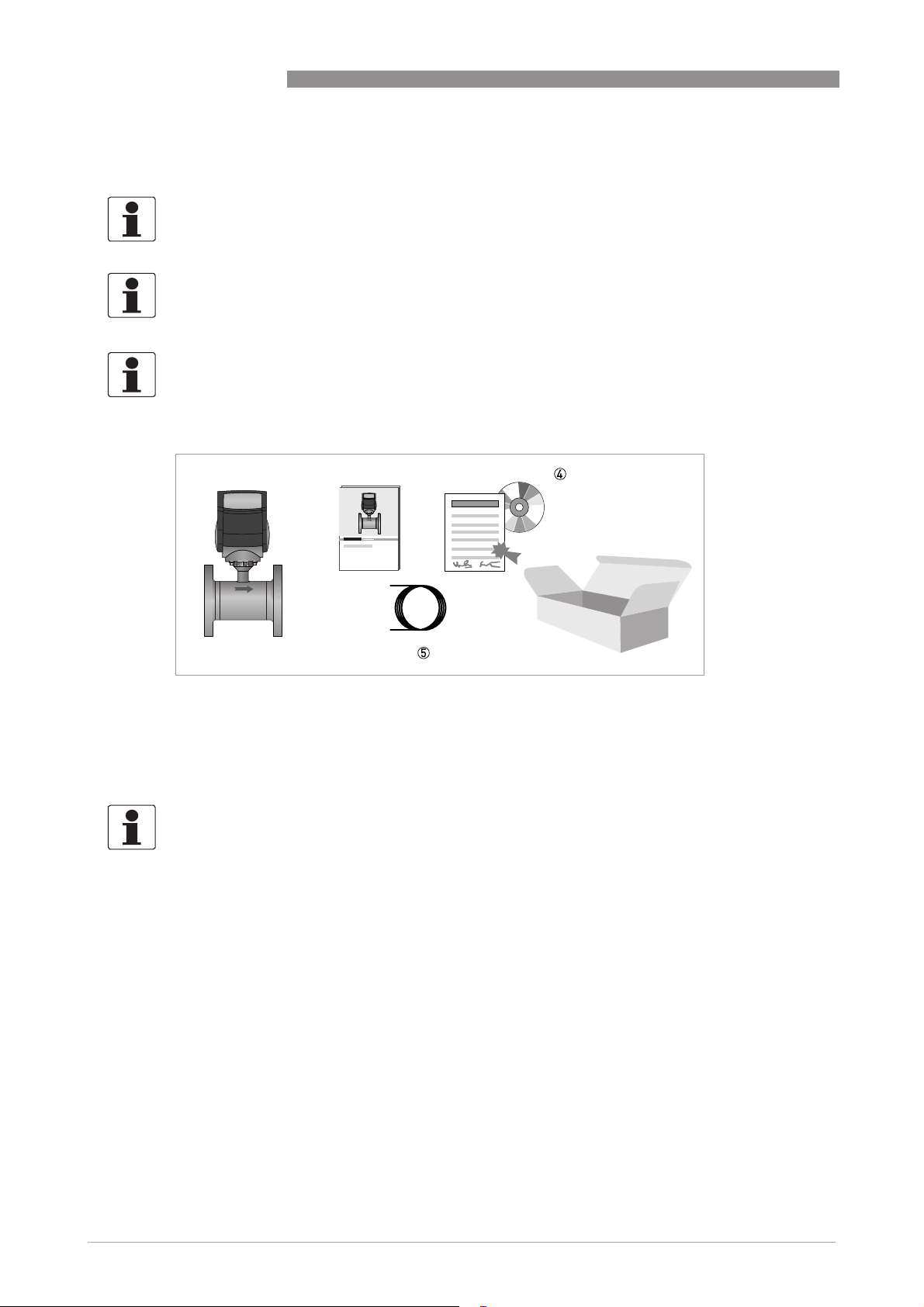
Figure 2-1: Scope of delivery
1 Ordered water meter
2 Product documentation
3 Factory calibration report
4 CD-ROM with product documentation in available languages
5 Signal cable (remote versions only)
INFORMATION!
Assembly materials and tools are not part of the delivery. Use the assembly materials and tools
in compliance with the applicable occupational health and safety directives.
6
www.krohne.com 06/2013 - 4002400602 - QS WATERFLUX 3070 R05 en
Page 7
WATERFLUX 3070
2.2 Device description
Your measuring device is supplied ready for operation. The factory settings for the operating
data have been made in accordance with your order specifications.
The following versions are available:
• Compact version (the signal converter is mounted directly on the measuring sensor) in
aluminium (IP67) or polycarbonate (IP68) housing
• Remote version (measuring sensor with connection box and a signal converter in a remote
(field) housing)
INSTALLATION 2
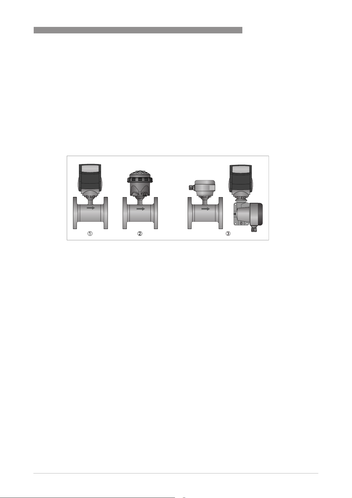
Figure 2-2: Device versions
1 Compact version in aluminium (IP67) housing
2 Compact version in polycarbonate (IP68) housing
3 Remote version
www.krohne.com06/2013 - 4002400602 - QS WATERFLUX 3070 R05 en
7
Page 8
2 INSTALLATION
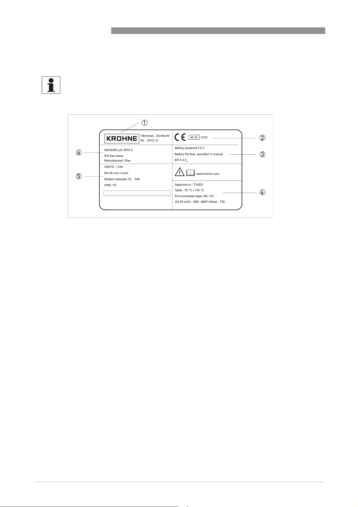
2.3 Nameplate
INFORMATION!
Check the device nameplate to ensure that the device is delivered according to your order.
WATERFLUX 3070
Figure 2-3: Example of nameplate
1 Name and address of the manufacturer
2 CE sign with number(s) of notified body / bodies
3 Battery voltage and Electronic Revision number
4 Optional (MI-001): Additional information including approval number, Q3, ratio
5 Meter constant, diameter, wetted materials, protection class
6 Type designation of the flowmeter, serial number, date of manufacturing
8
www.krohne.com 06/2013 - 4002400602 - QS WATERFLUX 3070 R05 en
Page 9
WATERFLUX 3070
2.4 Storage
• Store the device in a dry and dust-free location.
• Avoid lasting direct exposure to the sun.
• Store the device in its original packaging.
• Storage temperature: -50 ...+70°C / -58...+158°F
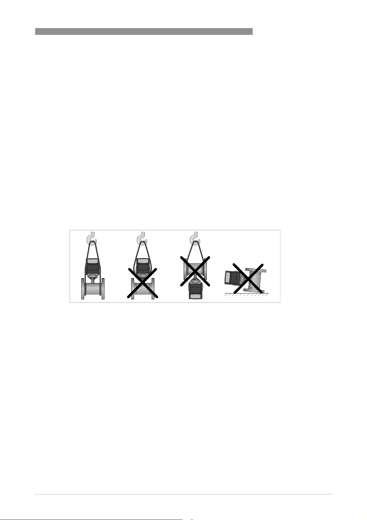
2.5 Transport
Signal converter
• No special requirements.
Compact version
• Do not lift the device by the signal converter housing.
• Do not use lifting chains.
• To transport flange devices, use lifting straps. Wrap these around both process connections.
INSTALLATION 2
Figure 2-4: Transport
2.6 Pre-installation requirements
Make sure that you have all necessary tools available:
• Allen key (4 mm)
• Small screwdriver
• Wrench for cable glands
• Wrench for wall mounting bracket (remote version only)
• Torque wrench for installing flowmeter in pipeline
www.krohne.com06/2013 - 4002400602 - QS WATERFLUX 3070 R05 en
9
Page 10
2 INSTALLATION
2.7 General requirements
INFORMATION!
The following precautions must be taken to ensure reliable installation.
•
Make sure that there is adequate space to the sides.
•
Protect the signal converter from direct sunlight and install a sun shade if necessary.
•
Signal converters installed in control cabinets require adequate cooling, e.g. by fan or heat
exchanger.
•
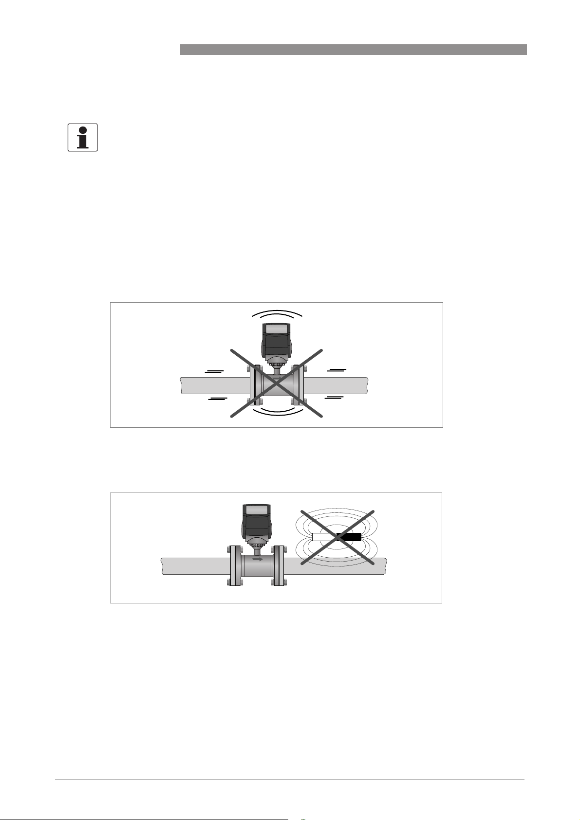
Do not expose the signal converter to intense vibration. The flowmeters are tested for a
vibration level in accordance with IEC 68-2-64.
2.7.1 Vibration
WATERFLUX 3070
Figure 2-5: Avoid vibrations
2.7.2 Magnetic field
Figure 2-6: Avoid magnetic fields
10
www.krohne.com 06/2013 - 4002400602 - QS WATERFLUX 3070 R05 en
Page 11

WATERFLUX 3070
2.8 Installation conditions
2.8.1 Inlet and outlet
DN25...300
Figure 2-7: Minimal inlet and outlet
1 Inlet: ≥ 0 DN
2 Outlet: ≥ 0 DN
INSTALLATION 2
DN350...600
Figure 2-8: Minimal inlet and outlet
1 Inlet: ≥ 3 DN
2 Outlet: ≥ 1 DN
2.8.2 T-section
Figure 2-9: Distance behind a T-section
1 DN 25...300: ≥ 0 DN & DN 350...600: ≥ 3 DN
www.krohne.com06/2013 - 4002400602 - QS WATERFLUX 3070 R05 en
11
Page 12

2 INSTALLATION
2.8.3 Bends
Figure 2-10: Installation in bending pipes
WATERFLUX 3070
12
Figure 2-11: Installation in bending pipes
CAUTION!
Avoid draining or partial filling of the flow sensor
www.krohne.com 06/2013 - 4002400602 - QS WATERFLUX 3070 R05 en
Page 13

WATERFLUX 3070
2.8.4 Open discharge
Figure 2-12: Installation in front of an open discharge
2.8.5 Pump
INSTALLATION 2
Figure 2-13: Recommended installation: behind a pump
1 Inlet: ≥ 3 DN
2.8.6 Control valve
Figure 2-14: Recommended installation: in front of a control valve
www.krohne.com06/2013 - 4002400602 - QS WATERFLUX 3070 R05 en
13
Page 14

2 INSTALLATION
2.8.7 Air venting and vacuum forces
Figure 2-15: Air venting
1 ≥ 5 m
2 Air ventilation point
WATERFLUX 3070
14
Figure 2-16: Vacuum
1 ≥ 5 m
www.krohne.com 06/2013 - 4002400602 - QS WATERFLUX 3070 R05 en
Page 15

WATERFLUX 3070
2.8.8 Mounting position and flange deviation
INSTALLATION 2
Figure 2-17: Mounting position and flange deviation
1 L
max
2 L
min
• Mount flow sensor either with signal converter aligned upwards or downwards.
• Install flow sensor in line with the pipe axis.
• Pipe flange faces must be parallel to each other.
CAUTION!
- L
Max. permissible deviation of pipe flange faces: L
max
≤ 0.5 mm / 0.02".
min
www.krohne.com06/2013 - 4002400602 - QS WATERFLUX 3070 R05 en
15
Page 16

2 INSTALLATION
2.8.9 IP68
The WATERFLUX 3000 flow sensor is rated IP68 (NEMA 4X/6P). It is suitable for submersion in
flooded measurement chambers and for subsurface installation.
The compact IFC 070 signal converter is available in:
• an aluminium housing suitable for IP66/67, NEMA 4/4X/6
• a polycarbonate housing suitable for IP68, NEMA 4/4X/6.
This version is suitable for periodic submersion in flooded measurement chambers. The
output cable has IP68 rated (military) connectors.
In case of continuous or long term submersion it is advised to select the field (remote)
version (IP66/67). Submersion under water is possible down to a depth of 5 meters.
The remote IFC 070 signal converter is available in:
• an aluminium housing suitable for IP66/67, NEMA 4/4X/6.
WATERFLUX 3070
Figure 2-18: IP68 versions
1 Submersible
2 Buried
12
16
www.krohne.com 06/2013 - 4002400602 - QS WATERFLUX 3070 R05 en
Page 17

WATERFLUX 3070
2.9 Mounting
2.9.1 Torques and pressures
The maximum pressure and torques values for the flowmeter are theoretical and calculated for
optimum conditions and use with carbon steel flanges.
INSTALLATION 2
Figure 2-19: Tightening of bolts
Tightening of bolts
• Always tighten the bolts uniformely and in diagonally opposite sequence.
• Do not exceed the maximum torque value.
• Step 1: Apply approx. 50% of max. torque given in table.
• Step 2: Apply approx. 80% of max. torque given in table.
• Step 3: Apply 100% of max. torque given in table.
www.krohne.com06/2013 - 4002400602 - QS WATERFLUX 3070 R05 en
17
Page 18

2 INSTALLATION
WATERFLUX 3070
Nominal size
DN [mm]
25 PN 16 4 x M 12 12
40 PN 16 4 × M 16 30
50 PN 16 4 × M 16 36
65 PN 16 8 × M 16 50
80 PN 16 8 × M 16 30
100 PN 16 8 × M 16 32
125 PN 16 8 × M 16 40
150 PN 10 8 x M 20 55
150 PN 16 8 × M 20 55
200 PN 10 8 × M 20 85
200 PN 16 12 x M 20 57
250 PN 10 12 x M 20 80
250 PN 16 12 x M 24 100
300 PN 10 12 x M 20 95
300 PN 16 12 x M 24 136
350 PN 10 16 x M 20 96
400 PN 10 16 x M 24 130
450 PN 10 20 x M 24 116
500 PN 10 20 x M 24 134
600 PN 10 20 x M 27 173
1 Th e to rqu e va lue s al so d epe nd o n variables (temperature, bolt material, gasket material, lubricants, etc.)
outside the control of the manufacturer. Therefore these values should be regarded as indicative only.
Pressure
r a t i n g
Bolts Max. torque
1
[Nm]
18
www.krohne.com 06/2013 - 4002400602 - QS WATERFLUX 3070 R05 en
Page 19

WATERFLUX 3070
INSTALLATION 2
Nominal size
[inches]
1 150 4 x 1/2" 4
1½ 150 4 x 1/2" 11
2 150 4 × 5/8" 18
2.5 150 8 x 5/8" 27
3 150 4 × 5/8" 33
4 150 8 × 5/8" 22
5 150 8 × 3/4" 33
6 150 8 × 3/4" 48
8 150 8 × 3/4" 66
10 150 12 x 7/8" 74
12 150 12 x 7/8" 106
14 150 2 12 × 1" 87
16 150 2 16 × 1" 84
18 150 2 16 × 1 1/8" 131
20 150 2 20 × 1 1/8" 118
24 150 2 20 × 1 1/4" 166
1 Th e to rqu e va lue s al so d epe nd o n variables (temperature, bolt material, gasket material, lubricants, etc.)
outside the control of themanufacturer. Therefore these values should be regarded as indicative only.
2 No full rating (max. 145 psi).
Flange class
[lb]
Bolts Max. torque
[lbs.ft]
1
www.krohne.com06/2013 - 4002400602 - QS WATERFLUX 3070 R05 en
19
Page 20

2 INSTALLATION
2.10 Mounting of the signal converter
INFORMATION!
Assembly materials and tools are not part of the delivery. Use the assembly materials and tools
in compliance with the applicable occupational health and safety directives.
2.10.1 IP67 housing, remote version
Pipe mounting
Pipe mounting
Pipe mountingPipe mounting
WATERFLUX 3070
Figure 2-20: Pipe mounting of the field housing
1 Fix the signal converter to the pipe.
2 Fasten the signal converter using standard U-bolts and washers.
3 Tighten the nuts.
Wall mounting
Wall mounting
Wall mountingWall mounting
No special requirements.
2.10.2 IP68 housing, compact version
20
Figure 2-21: Closing of IP68 housing
• Before closing the case of the converter, ensure that all surfaces in contact with the seals are
clean.
• Position the upper part of the case and tighten the lock ring.
• Use the wrench to tighten the ring as shown.
www.krohne.com 06/2013 - 4002400602 - QS WATERFLUX 3070 R05 en
Page 21

WATERFLUX 3070
3.1 Safety instructions
DANGER!
All work on the electrical connections may only be carried out with the power disconnected. Take
note of the voltage data on the nameplate!
DANGER!
Observe the national regulations for electrical installations!
WARNING!
Observe without fail the local occupational health and safety regulations. Any work done on the
electrical components of the measuring device may only be carried out by properly trained
specialists.
INFORMATION!
Look at the device nameplate to ensure that the device is delivered according to your order.
Check for the correct supply voltage printed on the nameplate.
ELECTRICAL CONNECTIONS 3
3.2 Grounding
Figure 3-1: Grounding
INFORMATION!
Grounding without grounding rings. The flow sensor is equipped with a reference electrode.
www.krohne.com06/2013 - 4002400602 - QS WATERFLUX 3070 R05 en
21
Page 22

3 ELECTRICAL CONNECTIONS
3.3 Connection of the signal cable
3.3.1 IP 67 housing (field version)
CAUTION!
To ensure smooth functioning, always use the signal cables included in the delivery.
INFORMATION!
The signal cable is only used for remote versions. The standard WSC-cable includes both
electrode and field current leads.
WATERFLUX 3070
Figure 3-2: Preparation of standard cable (both sides)
1 Shielding
2 Blue + green + yellow cable, used for field current (terminals 7, 8, 9)
3 Brown + white + violet cable, used for electrode signals (terminals 1, 2, 3)
4 Drain wires
Dimensions of cable
a b c d e f
mm 75 35 70 5 45 30
inch 3.0 1.4 2.8 0.2 1.8 1.2
22
Figure 3-3: Cable connection at sensor side, standard cable
1 Connect drain wires under screw
2 Connect shielding under clamp
www.krohne.com 06/2013 - 4002400602 - QS WATERFLUX 3070 R05 en
Page 23

WATERFLUX 3070
Figure 3-4: Cable connection at converter side, standard cable
1 Connect drain wires under screw
2 Connect shielding under clamp
• Prepare appropriate cable lengths as shown.
• Connect the wires as shown in the following table.
ELECTRICAL CONNECTIONS 3
Wire color Terminal Function
Brown 1 Reference electrode
White 2 Standard electrode signal
Violet 3 Standard electrode signal
Blue 7 Field current
Green 8 Field current
Yellow 9 No function
Drain wires Screws Shielding
www.krohne.com06/2013 - 4002400602 - QS WATERFLUX 3070 R05 en
23
Page 24

3 ELECTRICAL CONNECTIONS
3.4 Connection of the output cable
3.4.1 IP67 housing (compact and field version)
WATERFLUX 3070
Figure 3-5: Removing side cap
Figure 3-6: Terminal assignment
1 Status output 1 or pulse output C
2 Status output 2
3 Not used
4 Common ground
5 Pulse output A
6 Pulse output B
6
5
4
3
2
1
24
Electrical values
• Pulse output passive:
Pulse output passive:
Pulse output passive:Pulse output passive:
f ≤ 100 Hz; I ≤ 10 mA; U: 2.7...24 VDC (P ≤ 100 mW)
• Status output passive:
Status output passive:
Status output passive:Status output passive:
I ≤ 10 mA; U: 2.7...24 VDC (P ≤ 100 mW)
www.krohne.com 06/2013 - 4002400602 - QS WATERFLUX 3070 R05 en
Page 25

WATERFLUX 3070
3.4.2 IP68 housing (compact version)
Figure 3-7: Output cable at IP68 compact version
1 Color coded leads of output cable
If an output is activated, the output cable with the IP68 rated connector has the following leads:
Output cable with IP68 rated connectors with 5 color coded leads:
ELECTRICAL CONNECTIONS 3
Wire color Contact on
Function
connector
Yellow A Status output 1
White G Status output 2
Blue H Ground
Brown B Pulse output A
Green F Pulse output B
Pink C External battery +
Grey E External battery -
Electrical values
• Pulse output passive:
Pulse output passive:
Pulse output passive:Pulse output passive:
f ≤ 100 Hz; I ≤ 10 mA; U: 2.7...24 VDC (P ≤ 100 mW)
• Status output passive:
Status output passive:
Status output passive:Status output passive:
I ≤ 10 mA; U: 2.7...24 VDC (P ≤ 100 mW)
www.krohne.com06/2013 - 4002400602 - QS WATERFLUX 3070 R05 en
25
Page 26

4 START-UP
4.1 Connecting the internal battery
CAUTION!
Please connect the battery before first use. The signal converter is delivered
with a disconnected battery. In case the meter is verified to MI-001, the batteries are
already connected in the factory.
WATERFLUX 3070
Figure 4-1: Connecting the battery
• Remove the protection cap and loosen the 4 Allen bolts (4mm) (IP67 housing).
• Remove the cover.
• Fasten the battery connector to the internal connector in the converter.
• Check if the display lights up.
• Put back the cover.
WARNING!
Make sure that the battery cable is not jammed by the cover.
• Tighten the 4 bolts and put back the protection cap (IP67 housing).
• For closing the case of the converter in the IP68 housing, please refer to
compact version
on page 20.
IP68 housing,
INFORMATION!
The instrument now operates with default menu settings.
For configuration of these menu settings, please refer to Battery on page 28
26
www.krohne.com 06/2013 - 4002400602 - QS WATERFLUX 3070 R05 en
Page 27

WATERFLUX 3070
4.2 Connecting the external battery
4.2.1 IP67 housing (compact and field version)
• Remove the protection cap and loosen the 4 Allen bolts (4mm).
• Remove the cover.
• Remove one of the blind cable glands in the bottom of the converter housing.
• Remove the metal strip at the bottom of the housing (2 screws).
• Lead the cable of the external battery through the gland opening and mount the attached cable
gland loosely.
• Pull the cable to the top of the electronics.
• Fasten the battery connector to the internal connector in the converter.
• Check if the display lights up.
• Refit the metal strip at the bottom of the housing.
• Tighten the cable gland.
• Put back the cover.
WARNING!
Make sure that the battery cable is not jammed by the cover.
START-UP 4
• Tighten the 4 bolts and put back the protection cap (IP67 housing).
• For closing the case of the converter in the IP68 housing, please refer to
compact version
on page 20.
INFORMATION!
The instrument now operates with default menu settings.
For configuration of these menu settings, please refer to Battery on page 28
4.2.2 IP68 housing (compact version)
The output cable has two color coded leads for connecting the external battery. For detailed
information, please refer to
IP68 housing (compact version)
IP68 housing,
on page 25.
www.krohne.com06/2013 - 4002400602 - QS WATERFLUX 3070 R05 en
27
Page 28

4 START-UP
4.2.3 Battery
After a change of battery:
• Reset the bettery lifetime counter (Menu number B2)
• Select the battery type, if a different type of battery is used. (Menu number B0)
• Change the total battery capacity, if a different type of battery is used. (Menu number B1)
No. Function Options Description
WATERFLUX 3070
B0 Battery type 0 = No battery A wrong setting influences the
1 = One internal battery
(default)
2 = Two internal batteries
3 = External battery pack
B1 Total battery capacity xx.xxx = xx.xxx Ah
B2 Reset battery lifetime
counter
(19.000 Ah Default)
0 = Off (default) Set the value to 1 to reset the battery
1 = Reset
battery lifetime calculation.
Total of all batteries in Ah. After a
change to a different battery type,
change the setting (19 one battery,
38 two batteries, or 78 external
battery)
lifetime counter. After a reset, the
menu setting automatically goes
back to 0.
28
www.krohne.com 06/2013 - 4002400602 - QS WATERFLUX 3070 R05 en
Page 29

WATERFLUX 3070
5.1 Dimensions and weights
Remote flow sensor
Remote flow sensor a = 88 mm / 3.5"
Remote flow sensorRemote flow sensor
Remote version in
Remote version in
Remote version in Remote version in
aluminium housing
aluminium housing
aluminium housing aluminium housing
(IP67)
(IP67)
(IP67)(IP67)
TECHNICAL DATA 5
b = 139 mm / 5.5" 1
c = 106 mm / 4.2"
Total height = H + a
b = 132 mm / 5.2"
c = 235 mm / 9.3"
H = 310 mm / 12.2"
Weight = 3.3 kg / 7.3 lb
Compact version in
Compact version in
Compact version in Compact version in
aluminium housing
aluminium housing
aluminium housing aluminium housing
(IP67)
(IP67)
(IP67)(IP67)
Compact version in
Compact version in
Compact version in Compact version in
polycarbonate housing
polycarbonate housing
polycarbonate housing polycarbonate housing
(IP68)
(IP68)
(IP68)(IP68)
1 The value may vary depending on the used cable glands.
a = 170 mm / 6.7"
b = 132 mm / 5.2"
c = 140 mm / 5.5"
Total height = H + a
a = 159 mm / 6.3"
b = 161 mm / 6.3"
Total height = H + a
INFORMATION!
•
All data given in the following tables are based on standard versions of the flow sensor only.
•
Especially for smaller nominal sizes of the flow sensor, the signal converter can be bigger
than the flow sensor.
•
Note that for other pressure ratings than mentioned, the dimensions may be different.
•
For full information on signal converter dimensions see relevant documentation.
www.krohne.com06/2013 - 4002400602 - QS WATERFLUX 3070 R05 en
29
Page 30

5 TECHNICAL DATA
EN 1092-1
WATERFLUX 3070
Nominal size
DN [mm]
25 150 151 115 5
40 150 166 150 6
50 200 186 165 13
65 200 200 185 11
80 200 209 200 17
100 250 237 220 17
125 250 266 250 21
150 300 300 285 29
200 350 361 340 36
250 400 408 395 50
300 500 458 445 60
350 500 510 505 85
400 600 568 565 110
450 600 618 615 125
500 600 671 670 120
600 600 781 780 180
ASME B16.5 / 150 lb
Dimensions [mm] Approx. weight
[kg]
L H W
Nominal size
[inches]
Dimensions [inches] Approx. weight
[lb]
L H W
1 5.91 5.83 4.3 18
1½ 5.91 6 4.9 21
2 7.87 7.05 5.9 34
3 7.87 8.03 7.5 42
4 9.84 9.49 9.0 56
5 9.84 10.55 10.0 65
6 11.81 11.69 11.0 80
8 13.78 14.25 13.5 100
10 15.75 16.3 16.0 148
12 19.7 18.8 19.0 210
14 27.6 20.7 21 290
16 31.5 22.9 23.5 370
18 31.5 24.7 25 420
20 31.5 27 27.5 500
24 31.5 31.4 32 680
30
www.krohne.com 06/2013 - 4002400602 - QS WATERFLUX 3070 R05 en
Page 31

WATERFLUX 3070
6
www.krohne.com06/2013 - 4002400602 - QS WATERFLUX 3070 R05 en
31
Page 32

KROHNE product overview
• Electromagnetic flowmeters
• Variable area flowmeters
• Ultrasonic flowmeters
• Mass flowmeters
• Vortex flowmeters
• Flow controllers
• Level meters
• Temperature meters
• Pressure meters
• Analysis products
• Products and systems for the oil & gas industry
• Measuring systems for the marine industry
Head Office KROHNE Messtechnik GmbH
Ludwig-Krohne-Str. 5
47058 Duisburg (Germany)
Tel.:+49 (0)203 301 0
Fax:+49 (0)203 301 10389
info@krohne.de
The current list of all KROHNE contacts and addresses can be found at:
© KROHNE 06/2013 - 4002400602 - QS WATERFLUX 3070 R05 en - Subject to change without notice.
www.krohne.com
 Loading...