

Page 1
Supplementary instructions
Supplementary instructions
H250 M9
H250 M9
H250 M9H250 M9
Supplementary instructions Supplementary instructions
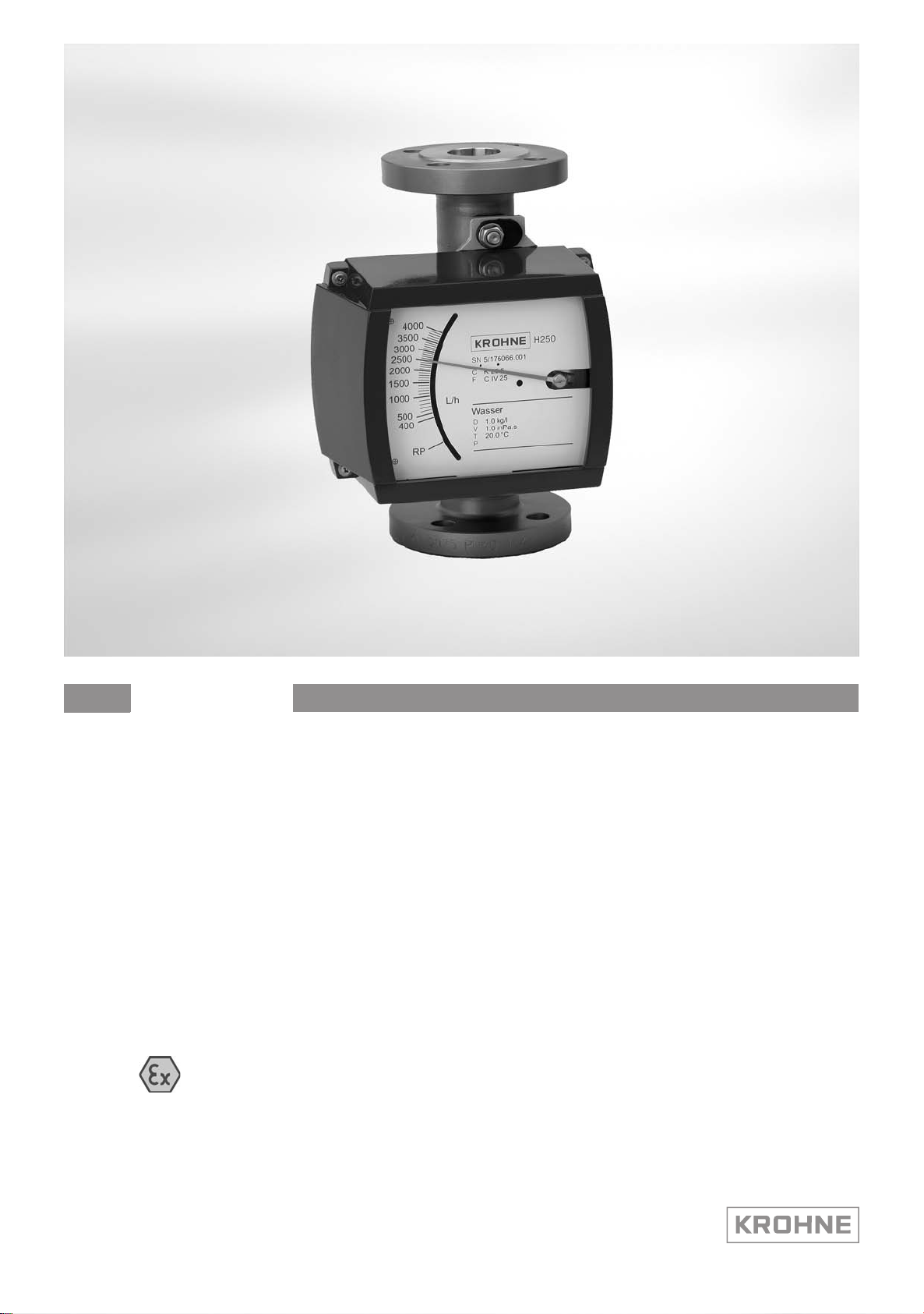
Variable area flowmeter
Equipment category II 3 G and II 3 D with electrical components
in protection type non-sparking 'nA' and
in protection type equipment - dust ignition protection 't'
© KROHNE 10/2012 - 4000646002 MA H250/M9-Ex-II3GD-AD-R06-en
Page 2

CONTENTS
H250 M9
1 Safety instructions 3
1.1 General notes ................................................................................................................... 3
1.2 EC conformity ................................................................................................................... 3
1.3 Security information......................................................................................................... 3
2 Device description 4
2.1 Device description ............................................................................................................ 4
2.2 Description code............................................................................................................... 4
2.3 Marking............................................................................................................................. 5
2.4 Flammable products ........................................................................................................ 6
2.5 Equipment category .........................................................................................................6
2.6 Types of protection ........................................................................................................... 7
2.6.1 Type of protection for gas hazard areas................................................................................. 7
2.6.2 Type of protection for dust hazard areas ............................................................................... 7
2.7 Ambient temperature / temperature classes.................................................................. 8
2.8 Surface temperature equipment category II 3 D ........................................................... 11
2.9
Electrical data....................................................................................................... 11
3 Installation 12
3.1 Installation...................................................................................................................... 12
4 Electrical connections 13
4.1 General notes ................................................................................................................. 13
4.2 Power supply .................................................................................................................. 14
4.3 Inputs/outputs ................................................................................................................ 14
4.4 Earthing and equipotential bonding ............................................................................... 14
5 Operation 15
5.1 Start-up........................................................................................................................... 15
5.2 Operation ........................................................................................................................ 15
5.3 Electrostatic charge .......................................................................................................15
6 Service 16
6.1 Maintenance ................................................................................................................... 16
6.2 Dismantling .................................................................................................................... 16
7 Notes 17
2
www.krohne.com 10/2012 - 4000646002 MA H250/M9-Ex-II3GD-AD-R06-en
Page 3

H250 M9
1.1 General notes
These additional Instructions apply to the explosion-protected versions of the variable-area
flowmeters with electrical components and the marking II 3 G and II 3 D. They are
supplementary to the Installation and Operation Instructions for the non-hazardous-duty
versions.
The information given in these Instructions contains only the data relevant to Category 3
explosion protection. The technical details given in the Installation and Operation Instructions for
the non-explosion protected versions apply unchanged unless excluded or superseded by these
Instructions.
1.2 EC conformity
The manufacturer declares with the EC Declaration of Conformity on his own responsibility
conformity with the protection goals of Directive 94/9/EC for use in hazardous areas with gas and
dust.
The assessment was made according to Directive 94/9/EC, Annex VIII (module "Internal control
of production"), and is registered company-internal under KMT-TDZ-A041X. This registration
number is also provided on the nameplate.
SAFETY INSTRUCTIONS 1
1.3 Security information
Assembly, installation, start-up and maintenance may only be performed by personnel trained in
explosion protection!
CAUTION!
The operator respectively his agent is responsible to follow further standards, directives or laws
if required due to operating conditions or place of installation. This applies particularly for the
use of easy detachable process connections such as SMS or Clamp when measuring flammable
mediums.
www.krohne.com10/2012 - 4000646002 MA H250/M9-Ex-II3GD-AD-R06-en
3
Page 4
2 DEVICE DESCRIPTION
2.1 Device description
Variable area flowmeters are used to measure and display volume flows of flammable and nonflammable gases and liquids. Depending on the device version, electrical limit switches and a 420 mA signal output or a Profibus PA interface can be built into the indicator part.
2.2 Description code
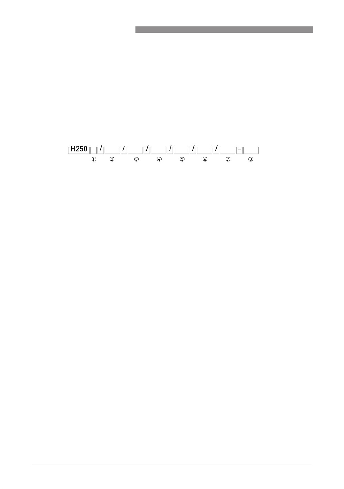
The safety description code * consists of the following elements:
1 Direction of flow
H - horizontal orientation
U - vertical downwards
no identifier - standard upwards
H250 M9
2 Materials / versions
RR - Stainless steel
C - PTFE or PTFE/ceramics
HC - Hastelloy
Ti - Titanium
F - Sterile version (food)
3 Heating jacket version
B - with heating jacket
4 Indicator part series
M9 - Indicator M9 standard indicator
M9S - Indicator with increased protection
M9R - Indicator in stainless steel housing
M9T - Indicator in stainless steel housing with increased protection
5 High-temperature version
HT version with HT extension
6 Electrical signal output
ESK - Electronic transmitter
7 Limit switch
K1 - One limit switch
K2 - Two limit switches
8 Explosion protection
Ex - Explosion-protected equipment
* positions which are not needed are omitted (no blank positions)
The indicator M9 standard version and M9R stainless steel version is not available for equipment
categories II 3 G and II 3 D.
4
www.krohne.com 10/2012 - 4000646002 MA H250/M9-Ex-II3GD-AD-R06-en
Page 5
H250 M9
2.3 Marking
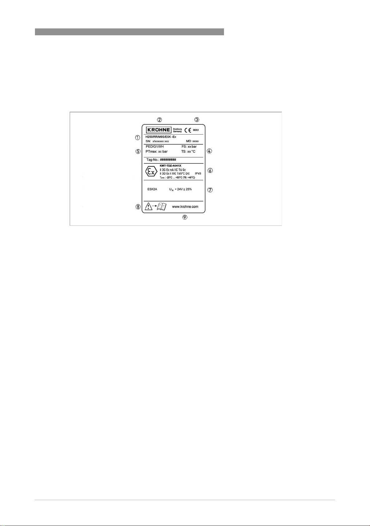
The marking of the entire device is on the display, where the following identification plate can be
found.
DEVICE DESCRIPTION 2
1 Device type according to description code
2 Manufacturer
3 Identification number of the notified body, Pressure Equipment Directive (PED)
4 Design data: temperature & pressure rating
5 DGRL data
6 Ex data
7 Electrical connection data
8 Note manual
9 KROHNE website
Additional markings on the device:
• SN - serial number
• SO - sales order / item
• KO - KROHNE order
• Vxxx - product configurator code
• AC - article code
Additional plate
The association of the housing cover to the device is confirmed by an additional plate with the
serial number on the interior of the indicator part.
www.krohne.com10/2012 - 4000646002 MA H250/M9-Ex-II3GD-AD-R06-en
5
Page 6

2 DEVICE DESCRIPTION
2.4 Flammable products
Atmospheric conditions:
Atmospheric conditions:
Atmospheric conditions:Atmospheric conditions:
An explosive atmosphere is a mixture of air and flammable gases, vapours, mists or dusts under
atmospheric conditions. The following values define it
= -20...+60°C / -4...+140°F and P
T
atm
Outside of this range, no key data are available as to ignition behaviour for most mixtures.
Installation condititions:
Installation condititions:
Installation condititions:Installation condititions:
Variable area flowmeters operate outside of atmospheric conditions, which means that
explosion protection according to Directive 94/9/EC (ATEX) – regardless of the zone assignment
– is fundamentally not applicable due to the lack of key safety data for the interior of the
measuring section.
WARNING!
Operation with flammable products is only permitted as long as no explosive fuel/air mixture
builds up on the inside of the flowmeter under operating conditions. The operator is responsible
for ensuring that the flowmeter is operated safely as regards the temperature and pressure of
the products used. In case of operation with flammable products the measuring units must be
included in the periodic pressure tests of the system. When using the device version H250/C...
(PTFE-liner, nonconductive) the min. conductivity of the medium must be 10
avoid the electrostatic charge.
= 0.8...1.1 bar.
atm
H250 M9
-8
S/m, in order to
2.5 Equipment category
The flowmeters are designed in category II 3G according to EN 60079-0 and EN 60079-15 and
category II 3D according to EN 60079-31 for use in hazardous areas, zone 2 and zone 22.
6
www.krohne.com 10/2012 - 4000646002 MA H250/M9-Ex-II3GD-AD-R06-en
Page 7
H250 M9
2.6 Types of protection
2.6.1 Type of protection for gas hazard areas
The variable area flowmeter is designed with protection type "non-sparking" 'nA' in accordance
with EN 60079-15. Protection against explosion is ensured in that no sparking contacts or hot
surfaces lead to ignition under normal operating conditions.
The marking is:
II 3G Ex nA IIC T6 Gc
II 3G Ex nA IIC T6 Gc
II 3G Ex nA IIC T6 GcII 3G Ex nA IIC T6 Gc
The marking contains the following information:
The marking contains the following information:
The marking contains the following information:The marking contains the following information:
II
II Group II explosion protection
IIII
3333 Equipment category 3
GGGG Gas explosion protection
Ex nA
Ex nA Protection type non-sparking
Ex nAEx nA
IIC
IIC Gas group, suitable for gas groups IIA, IIB, IIC
IICIIC
T6
T6 Temperature class, suitable for T6 ... T1
T6T6
Gc
Gc EPL, suitable for zone 2
GcGc
DEVICE DESCRIPTION 2
2.6.2 Type of protection for dust hazard areas
The variable area flowmeter is designed with protection type "protection by enclosure in
accordance with EN 60079-31. Dust protection is guaranteed by the use of a housing which
provides appropriate protection against penetration by dust.
The marking is:
II 3D Ex t IIIC T65
II 3D Ex t IIIC T65°C Dc
II 3D Ex t IIIC T65II 3D Ex t IIIC T65
IP65
IP65
IP65IP65
The marking contains the following information:
The marking contains the following information:
The marking contains the following information:The marking contains the following information:
II
II Group II explosion protection
IIII
3333 Equipment category 3
DDDD Dust explosion protection
Ex t
Ex t Protection type equipment 'dust ignition protection through housing'
Ex tEx t
IIIC
IIIC Dust group, suitable for dust groups IIIA, IIIB and IIIC
IIICIIIC
T65
T65°CCCC Maximum surface temperature without dust coating at ambient temperature 60°C / 140°F
T65T65
Dc
Dc EPL, suitable for zone 22
DcDc
IP65
IP65 Foreign bodies and water pollution control
IP65IP65
C Dc
C DcC Dc
and product temperature 60°C / 140°F
www.krohne.com10/2012 - 4000646002 MA H250/M9-Ex-II3GD-AD-R06-en
7
Page 8
2 DEVICE DESCRIPTION
2.7 Ambient temperature / temperature classes
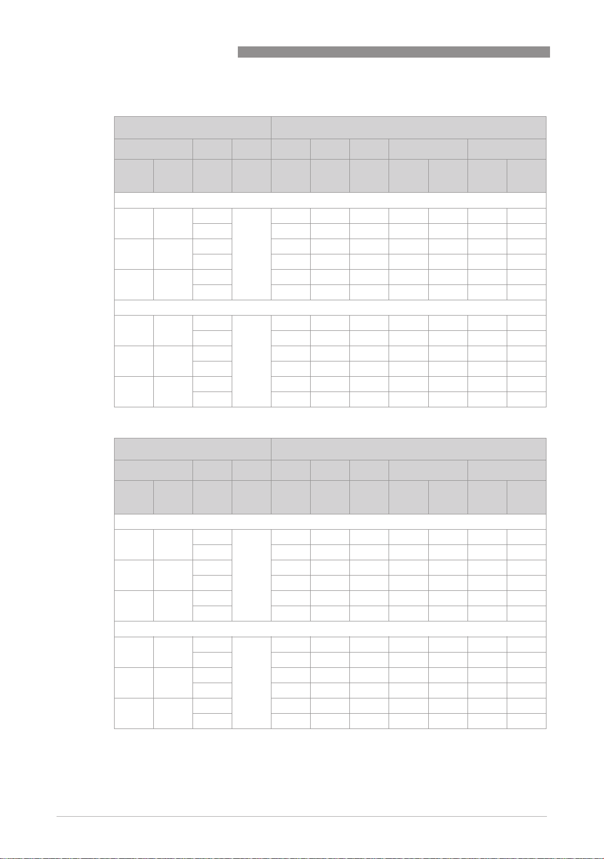
Due to the influence of the product temperature, variable area flowmeters with built-in electrical
equipment (electric variants) are not assigned to any fixed temperature class. The temperature
class of these devices is rather a function of the product temperature and ambient temperature
that is present and the specific device version. The classification is outlined in the following
tables.
The tables take into account the following parameters:
• Installed equipment
• Ambient temperature Tamb
• Product temperature Tm
• Nominal DN
• Standard or high temperature version (HT)
• Standard or heating jacket version
• Heat resistance of the connecting cable
When there is more than type of built-in equipment, the data of the most unfavourable
equipment should be used.
H250 M9
INFORMATION!
The maximum permissible product temperatures listed in the tables are valid under
the following conditions:
•
The measuring device is installed and operated in accordance with the installation
instructions in the installation and operating manual.
•
It must be ensured that the flowmeter is not heated by the effects of additional heat radiation
(sunshine, neighbouring system components) and thus operated above the permissible
ambient temperature range.
•
Insulation must be limited to the piping.
Unobstructed ventilation of the indicator part must be ensured
To do this, the variant with a projecting indicator (HT version) is preferable.
•
For device versions with a heating jacket, that the temperature of the heating medium does
not exceed the maximum permissible product temperature.
For certain device version, lower values apply due to differing boundary conditions (e.g. lining
materials).
Here the user should consult the technical data sheet.
8
www.krohne.com 10/2012 - 4000646002 MA H250/M9-Ex-II3GD-AD-R06-en
Page 9
H250 M9
DEVICE DESCRIPTION 2
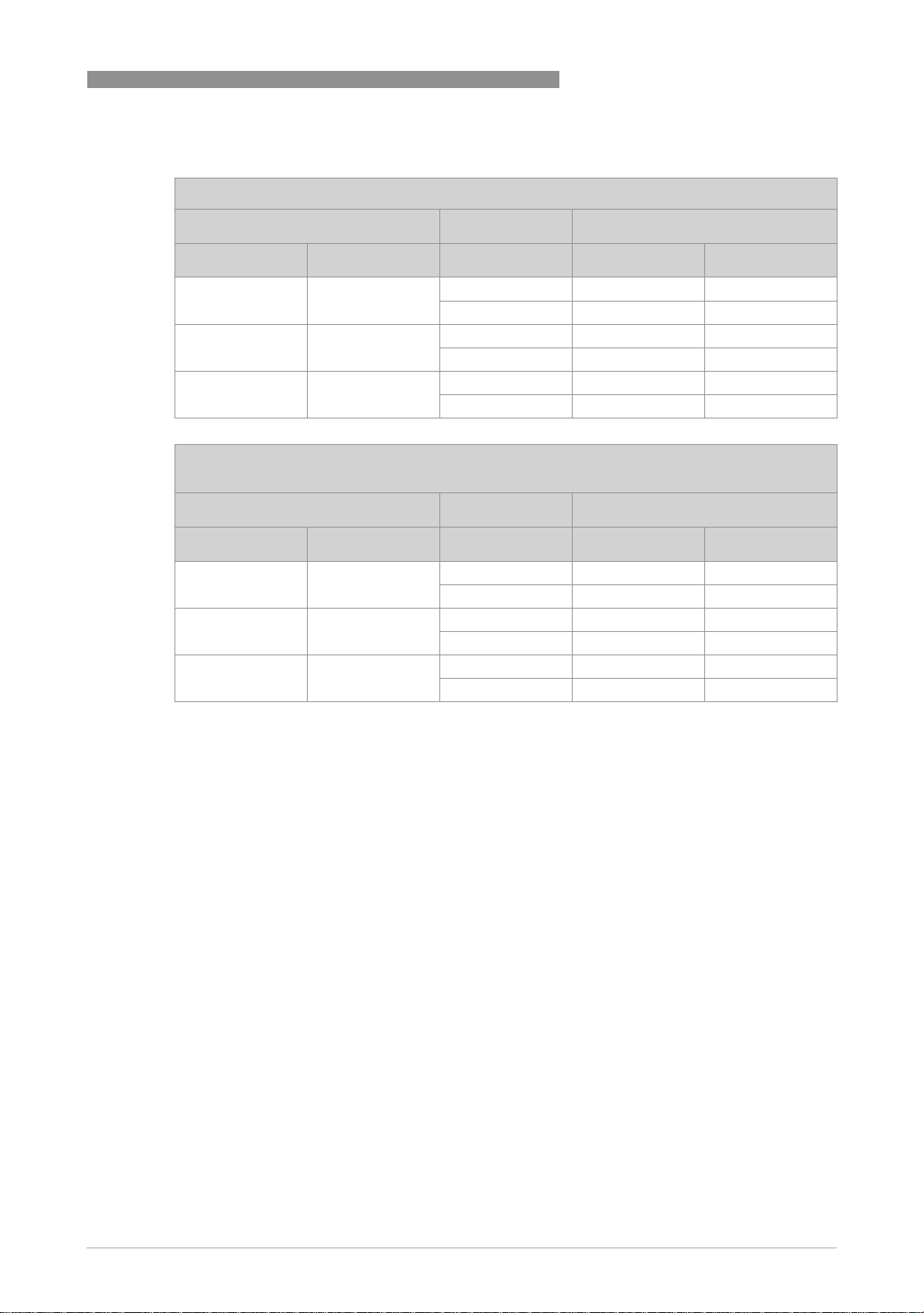
Using a heat resistant connecting cable
Temperature table in °C
Heating jacket Tm 1
none with HT-version T
DN15, DN25 DN15 - 150
x - 236
DN50 DN25 - 127
x - 171
DN80, DN100 DN50, DN80 - 109
x - 145
≤ 40 T
amb
amb
Temperature table in °F
Heating jacket Tm 1
none with HT-version T
DN15, DN25 DN15 - 302
x - 456
DN50 DN25 - 260
x - 340
DN80, DN100 DN50, DN80 - 228
x - 293
≤ 104 T
amb
amb
≤ 60
≤ 140
1 Maximum value of the product temperature for the use of a standard connecting cable. For
higher product temperatures a connecting cable with a temperature resistance of 100°C / 212°F
is required.
HT version - high-temperature version with projecting indicator
The permitted ambient temperature range is indicated on the nameplate; depending on the
device version it is T
= -40...+60°C / -40...+140°F or T
amb
= -25...+60°C / -13...+140°F.
amb
www.krohne.com10/2012 - 4000646002 MA H250/M9-Ex-II3GD-AD-R06-en
9
Page 10
2 DEVICE DESCRIPTION
Maximum permitted product temperature in
Maximum permitted product temperature in °C
Maximum permitted product temperature in Maximum permitted product temperature in
H250 M9
C
CC
Maximum permitted product temperature T
m
Heating jacket TK T6 T5 T4 T3 T2, T1
none with HT
Version
ESK II / ESK2A and ESK3-PA
DN15,
DN25
DN50 DN25 85 100 135 200 165 200 165
DN80,
DN100
K1 / K2
DN15,
DN25
DN50 DN25 85 100 135 200 200 200 200
DN80,
DN100
DN15 85 100 135 200 183 200 183
x 85 100 135 200 200 300 300
x 85 100 135 200 200 300 300
DN50,
DN80
DN15 85 100 135 200 200 200 200
DN50,
DN80
x 85 100 135 200 200 300 252
x 85 100 135 200 200 300 300
x 85 100 135 200 200 300 300
x 85 100 135 200 200 300 300
T
≤ 40 ≤ 60 ≤ 60 ≤ 40 ≤ 60 ≤ 40 ≤ 60
amb
85 100 135 200 150 200 150
85 100 135 200 200 200 200
Maximum permitted product temperature in
Maximum permitted product temperature in °F
Maximum permitted product temperature in Maximum permitted product temperature in
Maximum permitted product temperature T
F
FF
m
Heating jacket TK T6 T5 T4 T3 T2, T1
none with HT
Version
ESK II / ESK2A and ESK3-PA
DN15,
DN25
DN50 DN25 185 212 275 392 329 392 329
DN80,
DN100
K1 / K2
DN15,
DN25
DN50 DN25 185 212 275 392 392 392 392
DN80,
DN100
DN15 185 212 275 392 361 392 361
x 185 212 275 392 392 572 572
x 185 212 275 392 392 572 572
DN50,
DN80
DN15 185 212 275 392 392 392 392
DN50,
DN80
x 185 212 275 392 392 572 485
x 185 212 275 392 392 572 572
x 185 212 275 392 392 572 572
x 185 212 275 392 392 572 572
T
≤ 104 ≤ 140 ≤ 140 ≤ 104 ≤ 140 ≤ 104 ≤ 140
amb
185 212 275 392 302 392 302
185 212 275 392 392 392 392
10
www.krohne.com 10/2012 - 4000646002 MA H250/M9-Ex-II3GD-AD-R06-en
Page 11
H250 M9
DEVICE DESCRIPTION 2
2.8 Surface temperature equipment category II 3 D
For use in areas with flammable dust it should be noted that the indicated maximum surface
temperature of T65°C at an ambient temperature of 60°C / 140°F and a product temperature of
65°C / 149°F is valid without a dust coating. For higher product temperatures the maximum
surface temperature is determined by the product.
2.9
Electrical data
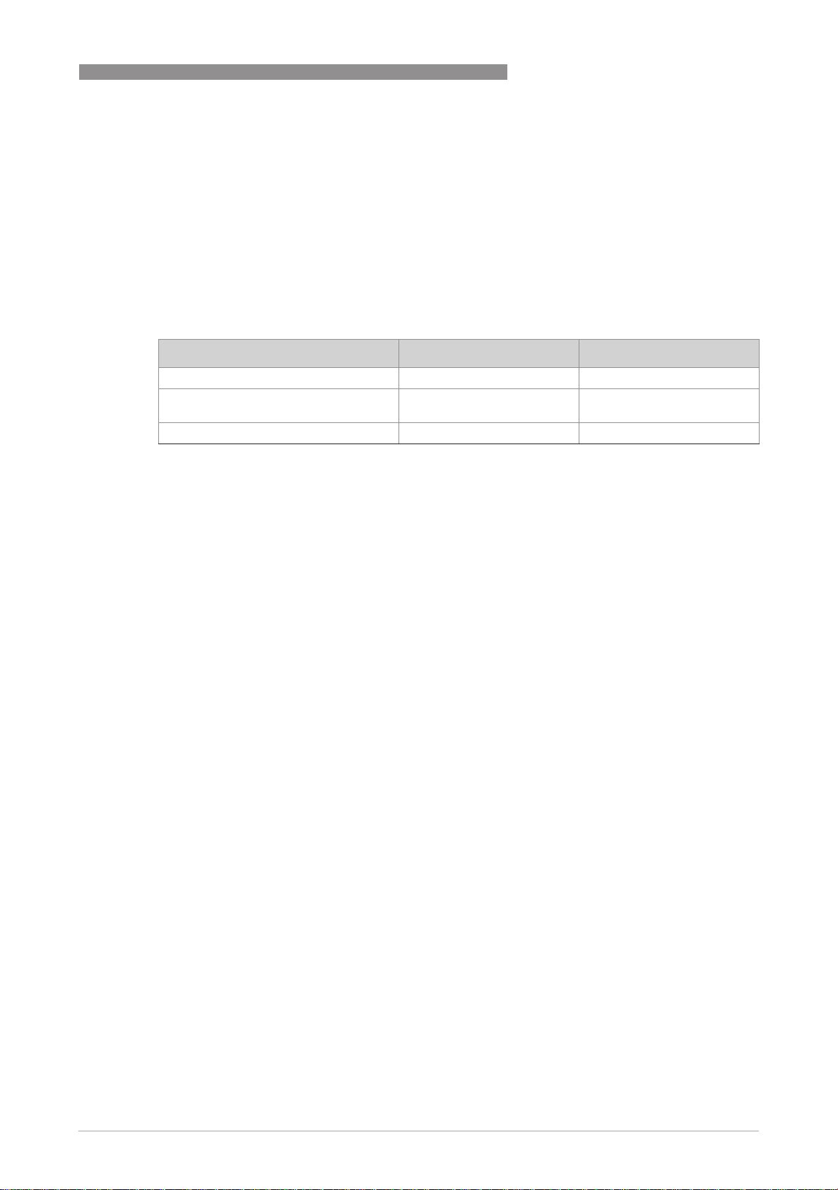
Electrical equipment Nominal voltage Nominal current
Limit switch K1 / K2 8VDC 1...3 mA
Signal output ESK II and ESK2A 24 VDC ± 25% 4...20 mA
ESK3-PA Profibus transmitter 1 9...32 VDC 12 mA
1 Further information and instructions for operation of the ESK3-PA Profibus transmitter are provided in separate sup-
plementary instructions.
with HART communication
www.krohne.com10/2012 - 4000646002 MA H250/M9-Ex-II3GD-AD-R06-en
11
Page 12

3 INSTALLATION
3.1 Installation
Installation and setup must be carried out according to the applicable installation installation
standards (e.g. EN 60079-14) by qualified personnel trained in explosion protection. The
information given in the Installation and Operation Instructions and the Supplementary
Installation and Operation Instructions must always be observed.
Variable area flowmeters must be installed in such a way that
• There is no danger from mechanical impact effects.
• There are no external forces affecting the indicator part.
• The device is accessible for any visual inspections that are necessary, and can be viewed from
all sides.
• The nameplate is clearly visible.
• It can be operated from a location with secure footing.
The variable area flowmeter can withstand the low risk of mechanical damage according to EN
60079-0 (impact energy 4/2 joules).
H250 M9
CAUTION!
The manufacturer is not liable for any damage resulting from improper use or use for other than
the intended purpose. This applies in particular to hazards due to insufficient corrosion
resistance and suitability of the materials in contact with product.
12
www.krohne.com 10/2012 - 4000646002 MA H250/M9-Ex-II3GD-AD-R06-en
Page 13

H250 M9
4.1 General notes
Electrical connection of the signal circuits is carried out in the integrated terminal compartment
of the indicator part. Separate conduit entries are provided for the signal output and limit
switches.
Unused conduit entries should be closed using approved blind plugs and seals. Ensure that the
seals are tight.
The connecting cables should be selected according to the applicable installation standards (e.g.
EN 60079-14) and the maximum operating temperature. The outer diameter of the connecting
wires must be adapted to the sealing range of the cable entries (6...10 mm / 0.24...0.39"). The
connecting cables must be fixed and laid in such a way as to be sufficiently protected against
damage.
Before connecting or disconnecting the electric connecting cable of the device, ensure that all of
the cables leading to the signal converter are de-energised relative to each other and to the
reference potential of the hazardous area. This also applies to earthing conductors (FE) and
equipotential bonding conductors (PA).
ELECTRICAL CONNECTIONS 4
All cores that are not used must be securely connected to the earth potential of the hazardous
area or carefully insulated against each other and against ground (test voltage ≥ 500 V
eff
).
Cable entries / Blanking plugs
The variable area flowmeter is optionally equipped with one conduit entry and one blind plug or
two conduit entries. These elements guarantee protection against foreign bodies and water
(protection category) IP65 or greater according to EN 60529. The cable entries are sealed with a
plug. The plugs should be replaced with suitable connecting cables.
www.krohne.com10/2012 - 4000646002 MA H250/M9-Ex-II3GD-AD-R06-en
13
Page 14

4 ELECTRICAL CONNECTIONS
4.2 Power supply
The variable area flowmeter does not require any separate power supply. The necessary power
for the built-in electrical equipment is supplied via the signal circuits.
4.3 Inputs/outputs
The signal circuits of the variable area flowmeter may only be connected to downstream devices
or circuits that satisfy the requirements of protective extra-low voltage (PELV). The terminal
assignment of the built-in electrical equipment is described in the Standard Installation and
Operation Instructions.
Only circuits that are suitable for operation in Zone 2 / Zone 22 hazardous areas may be
connected. Outside of the flowmeter, measures must be taken to prevent the rated voltage from
being exceeded by more than 40% due to temporary faults.
Use a 50 mA microfuse when connecting the signal output (ESK II / ESK2A) to voltage sources
with a possible short-circuit current of more than 100 mA.
H250 M9
4.4 Earthing and equipotential bonding
The variable area flowmeter must be included in the equipotential bonding of the hazardous
area. This is done using the earth connection on the rear of the indicator part.
Shields should be securely connected to the earth potential of the hazardous area, and
connected to the terminal located in the indicator part via the shortest route. In the case of shield
earthing at both ends (e.g. for reasons of electromagnetic compatibility), adequate equipotential
bonding that reliably prevents potential differences is necessary between the two earthed ends
of the shield in order to avoid excessive equalising current.
14
www.krohne.com 10/2012 - 4000646002 MA H250/M9-Ex-II3GD-AD-R06-en
Page 15

H250 M9
5.1 Start-up
Start-up is only permitted when the variable area flowmeter:
• is correctly installed in the system and connected.
• has been checked for the proper state with regard to its installation and connection
requirements.
The user of the system must have it checked before start-up in compliance with the national
regulations for checks before startup.
5.2 Operation
Variable area flowmeters must be operated in such a way that they remain within the maximum
and minimum permissible temperatures and pressures and the electrical limit values.
Variable area flowmeters may only be operated if the equipment parts necessary for safety are
effective in the long run, and are not rendered inoperable during operation.
During operation it is only permitted to open the indicator if no explosive atmosphere is present.
OPERATION 5
5.3 Electrostatic charge
In order to avoid ignition hazards due to electrostatic charge, variable area flowmeters
may not be used in areas where the following appear:
• processes that generate large charges,
• machines with friction and cutting processes,
• spraying of electrons (e.g. in the vicinity of electrostatic painting systems),
• dust carried by compressed air.
www.krohne.com10/2012 - 4000646002 MA H250/M9-Ex-II3GD-AD-R06-en
15
Page 16
6 SERVICE
6.1 Maintenance
Maintenance work of a safety-relevant nature within the meaning of explosion protection may
only be carried out by the manufacturer, his authorised representative or under the supervision
of authorised inspectors.
For systems in hazardous areas, regular tests are required in order to maintain the proper
condition.
The following checks are recommended:
• Checking the housing, the cable entries and the feed lines for corrosion and/or damage.
• Checking the measuring unit and the piping connections for leakage.
• Checking the measuring unit and the indicator for dust deposits.
CAUTION!
Avoid electrostatic charges when cleaning the sight window!
H250 M9
6.2 Dismantling
Exchanging the built-in equipment
Due to the modular structure of the variable area flowmeters, from a safety point of view it is
possible to exchange the electrical equipment built into the indicator for identical spare parts.
To do this, remove the housing cover. The housing cover must be closed immediately after the
spare parts are exchanged. Make sure that the cover seal is properly seated. The fastening
screws of the housing cover should be tightened with a torque of 1.2 Nm.
CAUTION!
There may be a loss of measuring accuracy!
Exchanging the entire device
Removal and installation is the user's responsibility.
Before disconnecting the electric connecting cable of the device, it must be ensured that all of
the cables leading to the indicator part are de-energised relative to each other and to the
reference potential of the hazardous area. This also applies to functional earthing conductors
(FE) and equipotential bonding conductors (PA).
CAUTION!
•
Pressurized pipes must be depressurized before removing the measuring section.
•
In the case of environmentally critical or hazardous products, appropriate safety precautions
must be taken with regard to residual liquids in the measuring section.
•
New seals must be used when re-installing the device in the piping.
16
www.krohne.com 10/2012 - 4000646002 MA H250/M9-Ex-II3GD-AD-R06-en
Page 17

H250 M9
NOTES 7
www.krohne.com10/2012 - 4000646002 MA H250/M9-Ex-II3GD-AD-R06-en
17
Page 18

7 NOTES
H250 M9
18
www.krohne.com 10/2012 - 4000646002 MA H250/M9-Ex-II3GD-AD-R06-en
Page 19

H250 M9
NOTES 7
www.krohne.com10/2012 - 4000646002 MA H250/M9-Ex-II3GD-AD-R06-en
19
Page 20

KROHNE product overview
• Electromagnetic flowmeters
• Variable area flowmeters
• Ultrasonic flowmeters
• Mass flowmeters
• Vortex flowmeters
• Flow controllers
• Level meters
• Temperature meters
• Pressure meters
• Analysis products
• Products and systems for the oil & gas industry
• Measuring systems for the marine industry
Head Office KROHNE Messtechnik GmbH
Ludwig-Krohne-Str. 5
47058 Duisburg (Germany)
Tel.:+49 (0)203 301 0
Fax:+49 (0)203 301 10389
[email protected]
© KROHNE 10/2012 - 4000646002 MA H250/M9-Ex-II3GD-AD-R06-en - Subject to change without notice.
The current list of all KROHNE contacts and addresses can be found at:
www.krohne.com
 Loading...