

Page 1
Parameter Guide
2E
Page 2
OG
PG
1 2 3
About this manual
This “Parameter Guide” contains explanations and other
information regarding the operations of the parameters and
settings on the X50/microX. The explanations are organized
by mode, page, and tab. Explanations and other information
on the effects and their parameters are also provided for
each effect.
Refer to this guide when an unfamiliar parameter appears in
the display, or when you need to know more about a particular function.
Conventions in this manual
Abbreviations for the manuals, OG, PG
References to the manuals included with the X50/microX
are abbreviated as follows.
: Operation Guide
: Parameter Guide
Explanations specific to the X50 or microX
This parameter guide is written for both the X50 and the
microX. Explanations that apply only to one or the other
model are preceded by an indication of “
in the text.
Switches and knobs [ ]
References to the buttons, dials, and knobs on the X50/
microX’s panel are enclosed in square brackets [ ].
included in the CD-ROM)
(
X50: ” or “ microX: ”
Parameters in the LCD display screen “ ”
Parameters displayed in the LCD screen are enclosed in
double quotation marks “ ”.
Boldface type
Parameter values are printed in boldface type.
Content that is of particular importance is also printed in
boldface type.
Procedure steps
Steps in a procedure are listed as
☞
p.
■
,
☞
OG p.
From the left, these symbols indicate a reference page in the
Parameter Guide, a reference page in the Operation Guide,
and a parameter number.
■
1
,
☞■
2
–
3
■
...
...
Symbols , , , , ,
These symbols respectively indicate cautions, advice, MIDIrelated explanations, a parameter that can be selected as an
alternate modulation source, a parameter that can be
selected as a dynamic modulation source, and a parameter
that can use the BPM/MIDI Sync function.
Example screen displays
The values of the parameters shown in the example screens
of this manual are only for explanatory purposes, and may
not necessary match the values that appear in the LCD
screen of your instrument.
MIDI-related explanations
CC# is an abbreviation for Control Change Number.
In explanations of MIDI messages,
brackets [ ]
always indicate hexadecimal numbers.
numbers in square
How to read the “Parameter Guide”
(example)
Mode name
Page No.
Tab No.
Tab name
Parameter
No.
Parameter
name
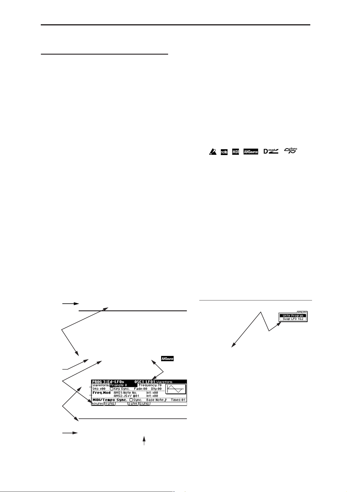
PROG 3: Ed–LFOs
Here you can make settings for the LFO that can be used to
cyclically modulate the Pitch, Filter, and Amp of oscillators 1
and 2. There are two LFO units for each oscillator . By setting
the LFO1 or LFO2 Intensity to a negative (–) value for Pitch,
Filter, or Amp, you can invert the LFO waveform.
3–1: OS1LFO1
Indicates settings for the “OSC1 LFO1,” which is the first
LFO that can be used for oscillator 1.
3–1a
3–1b
3–1c
3–1a: OSC1 LFO1
Waveform [Triangle 0…Random6 (Vect.)]
(OSC1 LFO1)
Page name
■ 3–1: UTILITY
☞ “Write Program” (0–1)
For details on how to select the desired utility function, refer
to “PROG 0–1: UTILITY.”
Swap LFO 1&2
This exchanges the settings of LFO 1 and 2. If LFO2 is
selected in AMS1 (Freq. AMS1) or AMS2 (Freq. AMS2) of
LFO1 Freq.Mod (3–1b), then these settings will be invalid for
LFO2 after LFO1 and 2 have been exchanged. If you select
this from the OSC1 LFO1 or OSC1 LFO2 page, LFO1 and
LFO2 of OSC1 will be exchanged.
1 Select “Swap LFO 1&2” to access the dialog box.
Utilty menu
command name
Range of possible parameter values
iii
Page 3

Table of Contents
1. Program mode........................... 1
PROG PAGE MENU....................................1
PROG 0: Play.............................................. 1
0–1: Program.......................................................... 1
0–2: P.Edit (Performance Editor)........................ 3
0–3: Arp (Arp. Play).............................................. 5
microX: 0–4: Ext. Control...................................... 5
PROG 1: Ed–Basic...................................... 6
1–1: Basic (Prog Basic).......................................... 6
1–2: OSC1............................................................... 7
1–3: OSC2............................................................... 9
1–4: V.Zone (Velocity Zone)................................9
1–5: Audition......................................................... 9
PROG 2: Ed–Pitch.................................... 10
2–1: OSC1............................................................. 10
2–2: OS1lfo (OSC1 LFO)..................................... 11
2–3: OSC2............................................................. 12
2–4: OS2lfo (OSC2 LFO)..................................... 12
2–5: EG (Pitch EG) .................................12
PROG 3: Ed–LFOs .................................... 14
3–1: OS1LFO1 (OSC1 LFO1) ................ 14
3–2: 1 LFO2 (OSC1 LFO2)..................................15
3–3: 2 LFO1 (OSC2 LFO1)..................................15
3–4: 2 LFO2 (OSC2 LFO2)..................................15
6–4: Lvl/Pan (Amp2 Level/Pan) ......................25
6–5: Mod. (Amp2 Modulation)..........................25
6–6: EG (Amp2 EG) ................................25
PROG 7: Ed–Arp/Ctrls (Arpeggiator/
Controls).................................................. 25
7–1: Setup (Arpeg. Setup)...................................25
7–2: Zone (Scan Zone).........................................27
7–3: Controls.........................................................27
PROG 8: Ed–InsertFX .............................. 28
8–1: BUS................................................................28
8–2: Setup..............................................................29
8–3: IFX (Insert Effect).........................................29
PROG 9: Ed–MasterFX ............................ 30
9–1: Setup..............................................................30
9–2: MFX 1 (Master Effect1)...............................31
9–3: MFX 2 (Master Effect2)...............................31
9–4: MEQ (Master EQ)........................................31
2. Combination mode ................. 33
COMBI PAGE MENU................................ 33
COMBI 0: Play.......................................... 33
0–1: Combi (Combination).................................33
0–2: Prog (Timbre Program) ..............................35
0–3: Mix (Mixer)...................................................36
0–4: Arp. A (Arpeggio Play A) ..........................37
0–5: Arp. B (Arpeggio Play B)............................37
microX: 0–6: Ext. Control ....................................37
iv
PROG 4: Ed–Filter1.................................. 16
4–1: Basic.............................................................. 16
4–2: Mod.1 (Filter1 Modulation1).....................17
4–3: Mod.2 (Filter1 Modulation2).....................18
4–4: lfoMod (LFO Modulation)......................... 18
4–5: EG (Filter1 EG) ...............................19
PROG 5: Ed–Filter2.................................. 21
5–1: Basic.............................................................. 21
5–2: Mod.1 (Filter2 Modulation1).....................21
5–3: Mod.2 (Filter2 Modulation2).....................21
5–4: lfoMod (LFO Modulation)......................... 21
5–5: EG (Filter2 EG) ...............................21
PROG 6: Ed–Amp1/2............................... 21
6–1: Lvl/Pan (Amp1 Level/Pan)...................... 21
6–2: Mod. (Amp1 Modulation)......................... 22
6–3: EG (Amp1 EG) ...............................23
COMBI 1: Ed–Tone Adjust...................... 38
1–1: Prog (Timbre Program) ..............................38
1–2: Mix (Mixer)...................................................38
1–3: TA1 (Tone Adjust 1)....................................38
1–4: TA2 (Tone Adjust 2)....................................38
1–5: TA3 (Tone Adjust 3)....................................38
COMBI 2: Ed–Timbre Param................... 40
2–1: MIDI ..............................................................40
2–2: OSC................................................................40
2–3: Pitch...............................................................41
2–4: Other..............................................................42
COMBI 3: Ed–MIDI Filter1....................... 42
3–1: MIDI 1–1 (MIDI Filter 1–1).........................42
3–2: MIDI 1–2 (MIDI Filter 1–2).........................43
3–3: MIDI 1–3 (MIDI Filter 1–3).........................43
3–4: MIDI 1–4 (MIDI Filter 1–4).........................43
Page 4

COMBI 4: Ed–MIDI Filter2....................... 44
4–1: MIDI 2–1 (MIDI Filter 2–1) ........................44
4–2: MIDI 2–2 (MIDI Filter 2–2) ........................44
X50: 4–3: MIDI 2–3 (MIDI Filter2–3).................44
X50: 4–4: MIDI 2–4 (MIDI Filter 2–4)................44
microX: 4–3: MIDI 2–3 (MIDI Filter2–3)........... 44
COMBI 5: Ed–Key Zone...........................45
5–1: Key (Key Zone)............................................45
5–2: Slope (Key Slope)........................................46
5–3: Review.......................................................... 46
COMBI 6: Ed–Vel Zone (Velocity Zone)
6–1: Vel (Velocity Zone).....................................46
6–2: Slope (Velocity Slope).................................47
6–3: Review.......................................................... 47
........ 46
COMBI 7: Ed–Arp/Ctrls (Arpeggiator/
Controls).................................................. 47
7–1: Setup .............................................................47
7–2: Arp. A (Arpeggiator A).............................. 48
7–3: Arp. B (Arpeggiator B)...............................48
7–4: Zone (Scan Zone) ........................................49
7–5: Controls........................................................ 50
COMBI 8: Ed–InsertFX.............................50
8–1: BUS................................................................ 50
8–2: Setup .............................................................51
8–3: IFX (Insert Effect) ........................................52
COMBI 9: Ed–MasterFX........................... 52
9–1: Setup .............................................................52
9–2: MFX1 (Master Effect1)................................53
9–3: MFX2 (Master Effect2)................................53
9–4: MEQ (Master EQ)........................................53
3. Multi mode ...............................55
1–2: TA1..16 (Tone Adjust1).............................. 59
1–3: TA2..8 (Tone Adjust2)................................ 59
1–4: TA2..16 (Tone Adjust2).............................. 59
1–5: TA3..8 (Tone Adjust3)................................ 59
1–6: TA3..16 (Tone Adjust3).............................. 59
MULTI 2: Track Param............................. 61
2–1: MIDI..8 (MIDI T01–08)............................... 61
2–2: MIDI..16 (MIDI T09–16)............................. 61
2–3: OSC..8 (OSC T01–08).................................. 62
2–4: OSC..16 (OSC T09–16)................................ 62
2–5: Ptch..8 (Pitch T01–08)................................. 62
2–6: Ptch..16 (Pitch T09–16)............................... 62
2–7: Othr..8 (Other T01–08) ............................... 63
2–8: Othr..16 (Other T09–16) ............................. 63
MULTI 3: MIDI Filter1.............................. 64
3–1: M1–1..8 (MIDI Filter1–1 T01–08) ..............64
3–2: 1–1..16 (MIDI Filter1–1 T09–16)................ 64
3–3: 1–2..8 (MIDI Filter1–2 T01–08).................. 64
3–4: 1–2..16 (MIDI Filter1–2 T09–16)................ 64
3–5: 1–3..8 (MIDI Filter2–1 T01–08).................. 64
3–6: 1–3..16 (MIDI Filter2–1 T09–16)................ 64
3–7: 1–4..8 (MIDI Filter2–2 T01–08).................. 65
3–8: 1–4..16 (MIDI Filter2–2 T09–16)................ 65
MULTI 4: MIDI Filter2.............................. 65
4–1: M2–1..8 (MIDI Filter2–1 T01–08) ..............65
4–2: 2–1..16 (MIDI Filter2–1 T09–16)................ 65
4–3: 2–2..8 (MIDI Filter2–2 T01–08).................. 66
4–4: 2–2..16 (MIDI Filter2–2 T09–16)................ 66
X50: 4–5: 2–3..8 (MIDI Filter2–3 T01–08) ......... 66
X50: 4–6: 2–3..16 (MIDI Filter2–3 T09–16) ....... 66
X50: 4–7: 2–4..8 (MIDI Filter2–4 T01–08) ......... 66
microX: 4–5: 2–3..8 (MIDI Filter2–3 T01–08).... 66
X50: 4–8: 2–4..16 (MIDI Filter2–4 T09–16) ....... 66
microX:
4–6: 2–3..16 (MIDI Filter2–3 T09–16)
..... 66
MULTI PAGE MENU.................................55
MULTI 0: Play........................................... 55
0–1: Multi..............................................................55
0–2: Prog..8 (Track Program T01...08) ..............57
0–3: Prog..16 (Track Program T09...16) ............57
0–4: Mix..8 (Mixer T01...08)................................ 58
0–5: Mix..16 (Mixer T09...16).............................. 58
microX: 0–6: Ext. Control....................................59
MULTI 1: Tone Adjust ............................. 59
1–1: TA1..8 (Tone Adjust1) ................................59
MULTI 5: Key Zone.................................. 67
5–1: Key..8 (Key Zone T01–08).......................... 67
5–2: Key..16 (Key Zone T09–16)........................ 67
5–3: Slp..8 (Key Slope T01–08) .......................... 67
5–4: Slp..16 (Key Slope T09–16) ........................ 67
5–5: Review.......................................................... 67
MULTI 6: Vel Zone (Velocity Zone)........ 68
6–1: Vel..8 (Velocity Zone T01–08) ...................68
6–2: Vel..16 (Velocity Zone T09–16) .................68
6–3: Slp..8 (Velocity Slope T01–08)................... 68
6–4: Slp..16 (Velocity Slope T09–16)................. 68
v
Page 5

6–5: Review.......................................................... 68
MULTI 7: Arp/Ctrls
(Arpeggiator/Controls).......................... 69
7–1: Set..8 (Setup T01–08)................................... 69
7–2: Set..16 (Setup T09–16)................................. 69
7–3: Arp. A (Arpeggiator A).............................. 70
7–4: Arp. B (Arpeggiator B)...............................70
7–5: Zone (Scan Zone)........................................ 70
7–6: Controls........................................................ 71
MULTI 8: InsertFX.................................... 72
8–1: BUS..8 (BUS T01...08).................................. 72
8–2: BUS..16 (BUS T09...16)................................ 72
8–3: Setup............................................................. 72
8–4: IFX (Insert Effect)........................................ 73
MULTI 9: MasterFX.................................. 73
9–1: Setup............................................................. 73
9–2: MFX1 (Master Effect1) ............................... 74
9–3: MFX2 (Master Effect2) ............................... 74
9–4: MEQ (Master EQ) .......................................74
4. Global mode............................. 75
GLOBAL PAGE MENU.............................. 75
GLOBAL 5: Arp.Pattern........................... 89
5–1: Setup..............................................................89
5–2: Edit ................................................................91
microX: GLOBAL 6: Ext. Control............. 93
6–1: A (Knob 1–A, 2–A, 3–A, 4–A)....................93
6–2: B (Knob 1–B, 2–B, 3–B, 4–B) .......................93
6–3: C (Knob 1–C, 2–C, 3–C, 4–C) .....................93
5. Demo Song............................... 95
Demo Song.............................................. 95
6. Effect Guide.............................. 97
Overview................................................. 97
1. Effects in each mode .......................................97
2. Dynamic modulation (Dmod).......................97
3. Effect I/O..........................................................97
Insert Effect (IFX) .................................... 98
1. In/Out...............................................................98
2. Routing..............................................................98
3. Mixer .................................................................99
4. Controlling the Insert Effects via MIDI......100
GLOBAL 0: System .................................. 75
0–1: Basic.............................................................. 75
0–2: Pref. (System Preference)...........................78
0–3: Foot ...............................................................80
GLOBAL 1: MIDI....................................... 81
1–1: MIDI.............................................................. 81
GLOBAL 2: User Scale ............................. 85
2–1: Octave........................................................... 85
2–2: All Notes ......................................................85
GLOBAL 3: Category Name .................... 86
3–1: P.0..7 (Prog.00...07)...................................... 86
3–2: P.8..15 (Prog.08...15).................................... 86
3–3: C.0..7 (Comb.00...07)................................... 86
3–4: C.8..15 (Comb.08...15)................................. 86
GLOBAL 4: DKit (Drum Kit)..................... 86
4–1: High (High Sample) ...................................86
4–2: Low (Low Sample) ..................................... 88
4–3: Voice (Voice/Mixer)................................... 88
Master Effects (MFX1, 2) ...................... 100
1. In/Out.............................................................100
2. Routing............................................................101
3. Mixer ...............................................................102
4. Controlling the Master Effects via MIDI....102
Master EQ..............................................103
Individual Outputs ............................... 103
Filter/Dynamic...................................... 104
00: No Effect .......................................................104
01: St.Amp Sim (Stereo Amp Simulation)......104
02: St.Compressor (Stereo Compressor).........104
03: St.Limiter (Stereo Limiter)..........................104
04: Mltband Limit (Multiband Limiter) .........105
05: St.Gate (Stereo Gate) ...................................106
06: OD/HiGain Wah
(Overdrive/Hi.Gain Wah).........................106
07: St.Para.4EQ
(Stereo Parametric 4-Band EQ)..................107
08: St.Graphic7EQ
(Stereo Graphic 7-Band EQ).......................108
09: St.Wah/AutoW
(Stereo Wah/Auto Wah)............................108
vi
Page 6

10: St.Rndm Filter (Stereo Random Filter).....109
11: St.Exct/Enhcr
(Stereo Exciter/Enhancer) .........................110
12: St.Sub OSC (Stereo Sub Oscillator)...........110
13: Talking Mod (Talking Modulator)...........111
14: St.Decimator (Stereo Decimator) ..............112
15: St.AnalogRecd (Stereo Analog Record)...112
Pitch/Phase Mod...................................113
16: St.Chorus (Stereo Chorus) .........................113
17: St.HarmnicCho
(Stereo Harmonic Chorus)......................... 113
18: MltTap ChoDly
(Multitap Chorus/Delay) ..........................114
19: Ensemble......................................................114
20: St.Flanger (Stereo Flanger) ........................115
21: St.Rndm Flang
(Stereo Random Flanger)........................... 115
22: St.Env.Flanger
(Stereo Envelope Flanger)..........................116
23: St.Phaser (Stereo Phaser) ...........................116
24: St.Rndm Phasr
(Stereo Random Phaser).............................117
25: St.Env.Phaser
(Stereo Envelope Phaser)...........................117
26: St.BiphaseMod
(Stereo Biphase Modulation)..................... 118
27: St.Vibrato (Stereo Vibrato).........................118
28: St.AutoFd Mod
(Stereo Auto Fade Modulation)................ 119
29: 2Voice Reso (2Voice Resonator)................119
30: Doppler.........................................................120
31: Scratch...........................................................121
Mod./P.Shift .......................................... 122
32: St.Tremolo (Stereo Tremolo) .....................122
33: St.Env.Tremlo
(Stereo Envelope Tremolo)........................122
34: St.Auto Pan (Stereo Auto Pan)..................123
35: St.Phasr+Trml
(Stereo Phaser + Tremolo) .........................123
36: St.Ring Mod (Stereo Ring Modulator)..... 124
37: Detune ..........................................................125
38: Pitch Shifter..................................................125
39: PitchShft Mod
(Pitch Shift Modulation).............................126
40: Rotary SP (Rotary Speaker).......................126
ER/Delay ................................................ 127
41: Early Reflect (Early Reflections) ...............127
42: Auto Reverse ...............................................128
43: LCR Delay (L/C/R Delay)........................128
44: St/Cross Dly (Stereo/Cross Delay)..........129
45: St.MltTap Dly (Stereo Multitap Delay) ... 129
46: St.Mod. Delay
(Stereo Modulation Delay)........................ 130
47: St.DynamicDly
(Stereo Dynamic Delay)............................. 130
48: St.AutoPanDly
(Stereo Auto Panning Delay)....................131
49: LCR BPM Delay (L/C/R BPM Delay)..... 131
50: St.BPM Delay (Stereo BPM Delay)........... 132
51: Sequence Dly (Sequence Delay) ............... 132
Reverb ................................................... 133
52: Rev Hall (Reverb Hall)............................... 133
53: Rev Smth. Hall
(Reverb Smooth Hall)................................. 133
54: Rev Wet Plate (Reverb Wet Plate)............ 133
55: Rev Dry Plate (Reverb Dry Plate)............. 133
56: Rev Room (Reverb Room)......................... 134
57: Rev Brt. Room (Reverb Bright Room) ..... 134
Mono → Mono Chain............................ 135
58: P4EQ–Exciter
(Parametric 4-Band EQ – Exciter)............. 135
59: P4EQ–Wah
(Parametric 4-Band EQ – Wah/Auto Wah) . 135
60: P4EQ–Cho/Fl
(Parametric 4-Band EQ – Chorus/Flanger)
61: P4EQ–Phaser
(Parametric 4-Band EQ – Phaser)............. 136
62: P4EQ–M.Dly
(Parametric 4-Band EQ – Multitap Delay)
63: Comp–Wah
(Compressor – Wah/Auto Wah).............. 137
64: Comp–AmpSim
(Compressor – Amp Simulation) ............. 138
65: Comp–OD/HG
(Compressor – Overdrive/Hi.Gain)........ 138
66: Comp–P4EQ
(Compressor – Parametric 4-Band EQ) ... 138
67: Comp–Cho/Fl
(Compressor – Chorus/Flanger).............. 139
68: Comp–Phaser (Compressor – Phaser)..... 139
69: Comp–M.Dly
(Compressor – Multitap Delay)................ 140
70: Limit–P4EQ
(Limiter – Parametric 4-Band EQ)............ 140
71: Limit–Cho/Fl
(Limiter – Chorus/Flanger) ...................... 141
72: Limit–Phaser (Limiter – Phaser)............... 141
73: Limit–M.Dly
(Limiter – Multitap Delay) ........................ 142
74: Exct–Comp (Exciter – Compressor)......... 142
75: Exct–Limiter (Exciter – Limiter) ............... 142
76: Exct–Cho/Fl
(Exciter – Chorus/Flanger).......................143
. 136
... 137
vii
Page 7

77: Exct–Phaser (Exciter – Phaser)..................143
78: Exct–M.Dly (Exciter – Multitap Delay) ... 143
79: OD/HG–AmpSim
(Overdrive/Hi.Gain – Amp Simulation)
80: OD/HG–Cho/Fl
(Overdrive/Hi.Gain – Chorus/Flanger)
81: OD/HG–Phaser
(Overdrive/Hi.Gain – Phaser)..................145
82: OD/HG–M.Dly
(Overdrive/Hi.Gain – Multitap Delay)...145
83: Wah–AmpSim
(Wah/Auto Wah – Amp Simulation)...... 146
84: Deci–AmpSim
(Decimator – Amp Simulation)................. 146
85: Deci–Comp
(Decimator – Compressor) ........................146
86: AmpSim–Trml
(Amp Simulation – Tremolo).................... 147
87: Cho/Fl–M.Dly
(Chorus/Flanger – Multitap Delay)......... 147
88: Phasr–Cho/Fl
(Phaser – Chorus/Flanger)........................ 148
89: Reverb–Gate ................................................148
....144
....144
Master EQ ..............................................149
Master EQ ..........................................................149
7. Appendices ............................151
Alternate Modulation Source (AMS)
About Alternate Modulation...........................151
About Alternate Modulation Sources ............151
AMS (Alternate Modulation Source) List
Alternate Modulation settings.........................154
The effect of alternate modulation on various
parameters, and example applications.....154
Dynamic Modulation Source (Dmod)
Dynamic Modulation Source List...................158
About the BPM/MIDI SYNC function...........160
X50: SW1/2 Assign................................ 161
SW1, SW2 Assign List.......................................161
Knob 1...4 B Assign...............................162
Realtime Control Knobs B Assign List...........162
Foot Switch Assign............................... 164
Foot Switch Assign List....................................164
Foot Pedal Assign.................................165
Foot Pedal Assign List......................................165
........ 151
.............152
....... 157
MIDI transmission when the X50/microX’s
controllers are operated......................166
X50/microX operations when control
changes are transmitted/received...... 168
MIDI applications.................................. 171
■
Messages transmitted and received by this
instrument......................................................171
Various messages................................. 180
X50, microX MUSIC SYNTHSIZER MIDI
IMPLEMENTATION................................ 181
Index...................................................... 184
• Apple, Mac and Audio Units are trademarks of Apple Computer ,
Inc., registered in the US. and other countries.
• Windows XP is a registered trademark of Microsoft Corporation
in the U.S. and other counties.
• VST is a trademark of Steinberg Media Technologies GmbH.
•RTAS is a registered trademark of Avid Technology, Inc., or its
subsidiaries or divisions.
• All other product and company names are trademarks or registered trademarks of their respective holders.
viii
Page 8
1. Program mode
1
2
3
4
→ 1
PROG
PROG PAGE MENU
Use the following procedure to select the desired page from
within the current mode.
Press the [MENU/OK] button to access the “PAGE
MENU.”
The “PAGE MENU” will show an abbreviated name for
each page.
Use the ClickPoint [ √ ][ ® ][ π ][ † ] to select a page.
Press the center of the ClickPoint to access the page.
If the selected page is divided into multiple pages, use
the PAGE [+][–] buttons to select the page you want.
Other ways to select a page
• Use the PAGE [+][–] buttons to move between tabs of a
page.
• Hold down the [MENU/OK] button and use the PAGE
[+][–] buttons to move forward or backward in the order
of pages 0
X50:
• Hold down the [MENU/OK] button and press one of
the numeric buttons [0]–[9] to move to the
corresponding page number. For example if you want to
move to the PROG 3: Ed–LFOs page, hold down the
[MENU/OK] button and press numeric button [3].
Play 0: Play Select and play programs.
Basic 1: Ed–Basic Set basic program parameters such as
Pitch 2: Ed–Pitch Pitch settings. Pitch EG settings. (☞p.10)
LFOs 3: Ed–LFOs Type and speed settings etc. for the two
Filter1 4: Ed–Filter1 Filter 1 (tone) settings. Filter EG settings.
Filter2 5: Ed–Filter2 Filter 2 (tone) settings. Filter EG settings.
Amp1/2 6: Ed–Amp1/2 Amp 1 and Amp 2 (volume) settings. Amp
Arp/Controls
Insert Effect
Master Effect
→2→3 etc.
7: Ed–Arp/Ctrls
8: Ed–InsertFX
9: Ed–MasterFX
Use the Performance Editor for easy editing, and to do simple editing of arpeggio
patterns.
microX: Select an external control set.
(☞p.1)
Oscillator and Multisample. (☞p.6)
LFOs provided for each oscillator. (Make
settings in the pitch, filter, and amp pages
to specify the depth of the LFO settings
you make here.) (☞p.14)
(☞p.16)
(☞p.21)
EG, pan (position) settings. (☞p.21)
Arpeggiator settings. (Shared with 0: Play
parameters. You may edit either.)
Controller settings. (☞p.25)
Select the BUS and master effect send
level for the oscillator output.
Insert Effect routing, selection and settings. (☞p.28)
Master Effect selection and settings. Master EQ settings. (☞p.30)
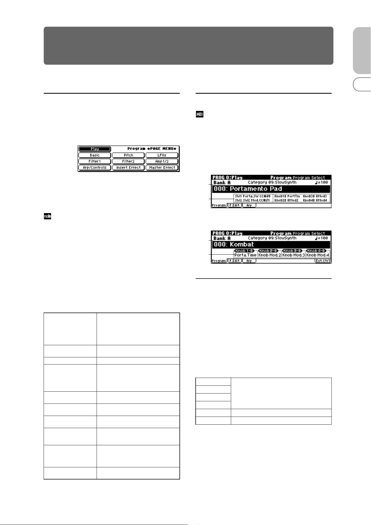
PROG 0: Play
In this display page you can select and play programs.
All MIDI data in PROG 0: Play is transmitted and
received on the Global MIDI Channel (☞GLOBAL 1–
1a).
0–1: Program
X50
0–1a
0–1b
microX
0–1a
0–1b
0–1a: Bank, Program Select, Category,
Cat. Hold, 10’s Hold, (Tempo)
Bank X50: [Bank A...D, G, g(d)]
microX: [Bank A...E, G, g(d)]
This is the program bank display.
X50: Use the PROG BANK [A]–[GM] buttons to select the
bank. The X50 provides rewritable banks A, B, C, and D,
each containing 128 programs (total 512). As for non-rewritable program areas, it provides banks G (capital programs
for GM), and bank g(d) (drums).
X50 Bank List
Bank A
Bank B
Bank C
Bank D
Bank G GM capital program
Bank g(d) GM drums program
Bank G will toggle between the GM and g(d) banks each
time you press the PROG BANK [GM] button.
for preloaded programs
(for user programs)
G→g(d)→ G→g(d)→G…
0
123456789
1
Page 9
microX: Use the PROGRAM [A]–[GM] buttons to select
the bank. The microX provides rewritable banks A, B, C, D,
and E, each containing 128 programs (total 640). As for nonrewritable program areas, it provides banks G (capital programs for GM), and bank g(d) (drums). If you press a PROGRAM [A]–[GM] button, you will automatically enter
Program mode even if you had been in a different mode.
microX Bank List
Bank A
Bank B
Bank C
Bank D
Bank E
Bank G GM capital program
Bank g(d) GM drums program
Bank G will toggle between the GM and g(d) banks each
time you press the PROGRAM [GM] button.
for preloaded programs
(for user programs)
G→g(d)→ G→g(d)→G…
Program Select
X50:
[(A…D)0…127: name, (G, g(d))1…128: name]
microX:
Here you can select a program.
Choose this parameter, and use one of the following methods to select a program.
[(A…E)0…127: name, (G, g(d))1…128: name]
To assign a category to each program, use the “Write
Program” (0–1) dialog box. To change the name of a category, use “Category Name Prog. 00–07, 08–15”
(☞GLOBAL 3–1/2).
X50: Cat. HOLD (Category Hold)
1 Press the [./HOLD] button to display . The
category will be held (fixed).
2 Use the ClickPoint [√][®][π][†] to choose “Category,”
and use the [INC][DEC] buttons or the [VALUE] dial to
select a category.
3 Use the ClickPoint [√][®][π][†] to choose “Program
Select,” and use the [INC][DEC] buttons or the [VALUE]
dial to successively select programs in that category.
4 To cancel, press the [./HOLD] button twice to turn off the
display.
If you press the [./HOLD] button in PROG 0: Play, the
selection will cycle in the order of →
→ Cancel.
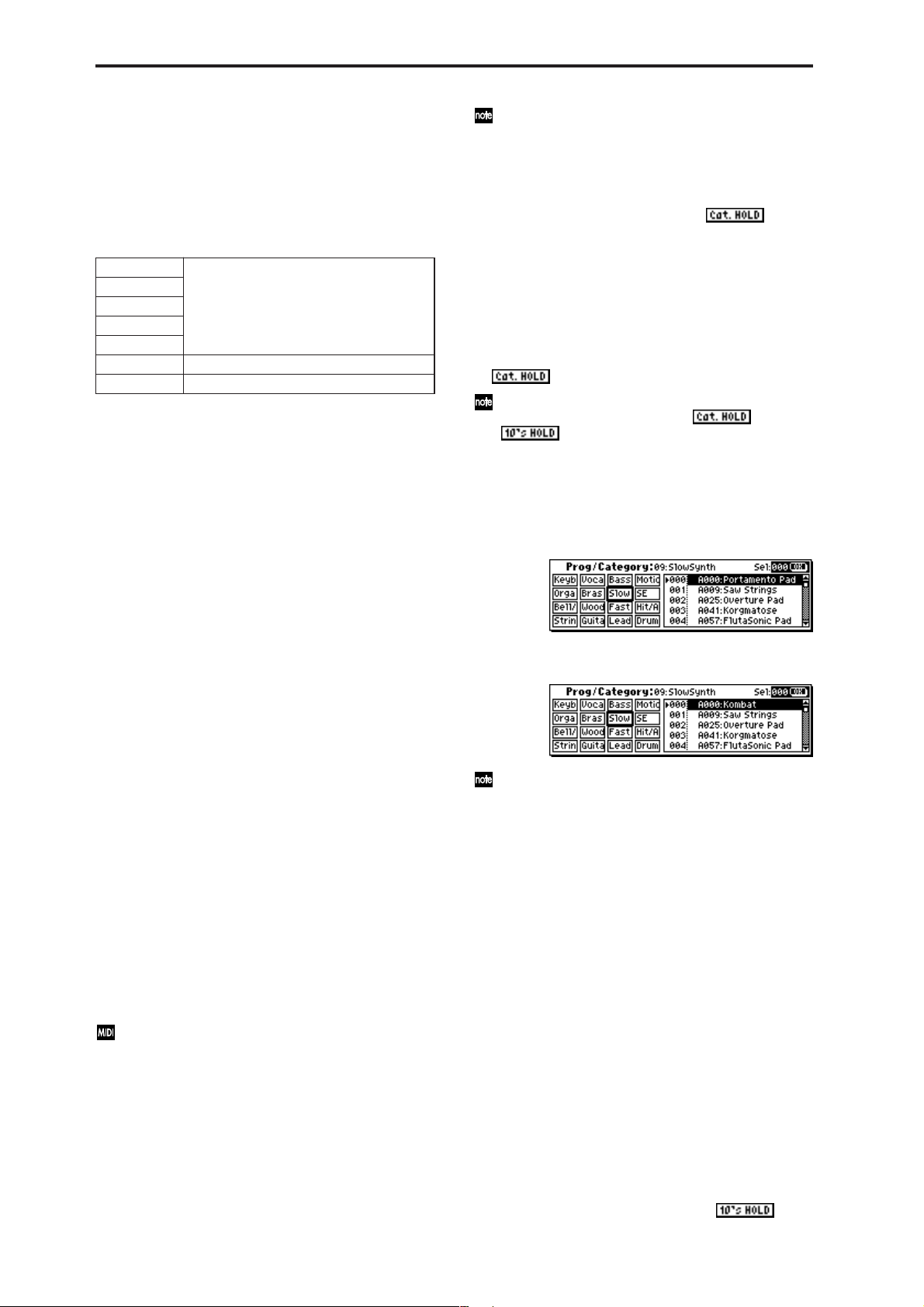
Select by Category
1 Press the [CATEGORY] button to access the category
menu (Prog/Category).
X50
X50:
• Turn the [VALUE] dial.
• Use the [INC][DEC] buttons.
• Use the numeric buttons [0]–[9] to enter a program
number, and press the [ENTER] button to finalize the
number.
• Press the center of the ClickPoint to highlight the field,
then use [π][†] to select a program, and press the
center to finalize your selection.
• 10’s HOLD (☞p.2)
• Use PROG BANK [A]–[GM] to select a bank (☞p.1)
• Use “Select by Category” to select by category (☞p.2)
• Use the foot switch (☞p.80, 164)
• Receive a MIDI program change (☞p.171)
microX:
• Turn the [VALUE] dial.
• Press the center of the ClickPoint to highlight the field,
then use [π][†] to select a program, and press the
center to finalize your selection.
• Use “Select by Category” to select by category (☞p.2)
• Use the [CATEGORY] button and PROGRAM/
COMBINATION buttons to select by category (☞p.2)
• Use the foot switch (☞p.80, 164)
• Receive a MIDI program change (☞p.171)
You can receive MIDI program changes from a connected external MIDI device, or use a foot switch to
select programs. (☞p.80 “Foot SW Assign” (GLOBAL
0–3a), p.164 “Foot Switch Assign List”)
Category [00...15: name]
Selects the program category.
All programs are classified into one of sixteen categories.
You can select the desired category, and then choose programs from that category.
To select a program by category, use the procedure
described below.
microX
Alternatively, you can access the category menu by
pressing the [UTILITY] button and choosing “Select by
Category” from the utility menu.
2 Use ClickPoint [√] to select “Prog/Category,” and use
the [VALUE] dial to select a category.
3 Use ClickPoint [π][†] to select a program. Alternatively ,
use the ClickPoint [®] to choose “Sel (Select),” and use
the [VALUE] dial to select a program.
4 Press the [MENU/OK] button to execute, or press the
[EXIT/CANCEL] button if you decide not to execute.
microX: Category & Bank
1 Press the [CATEGORY] button to access the category
menu (Prog/Category).
2 Note the categories shown below the PROGRAM buttons
or COMBINATION buttons, and pr ess the corresponding
button for the desired category. You can also use the
[PAGE+][PAGE–] buttons to step through the categories
one by one.
3 Use the [VALUE] dial to select a program.
4 Press the [MENU/OK] button to execute, or press the
[EXIT/CANCEL] button if you decide not to execute.
X50: 10’s HOLD
1 Press the [./HOLD] button to make the indi-
cation appear.
2
Page 10
The ten’s place of the program number will be fixed.
2 Now you can press a numeric button [0]–[9] to enter the
one’s place in a single action.
3 You can use the [INC][DEC] buttons to change the ten’s
place.
4 To defeat 10’s HOLD, press the [./HOLD] button to make
the indication disappear.
(Tempo) [040...240, EXT]
This sets the tempo of the arpeggiator. The tempo can also
be adjusted by the REALTIME CONTROLS C-mode
[TEMPO] knob.
EXT is shown if “MIDI Clock” (GLOBAL 1–1a) is set to ExtMIDI or Ext-USB, or if it is set to Auto and the unit is oper-
ating as a slave. The arpeggiator will synchronize to MIDI
clock messages from an external MIDI device.
You can also set this parameter from 7: Ed–Arp/Ctrls.
X50: You can tap the [ENTER] button several times to set
the tempo to the corresponding interval. Alternatively, if
you set the GLOBAL 0–3: Foot page “Foot SW Assign”
parameter to Tap Tempo, you can specify the tempo by tap-
ping your foot on a pedal switch connected to the ASSIGNABLE SWITCH jack.
microX: If you set the GLOBAL 0–3: Foot page “Foot SW
Assign” parameter to T ap Tempo, you can specify the tempo
by tapping your foot on a pedal switch connected to the
ASSIGNABLE SWITCH jack.
0–1b: Program Information
X50: This area shows the functions that are assigned to the
assignable switches [SW1] and [SW2], and to the REALTIME
CONTROLS B-mode [ASSIGNABLE 1]–[ASSIGNABLE 4]
knobs of the selected program.
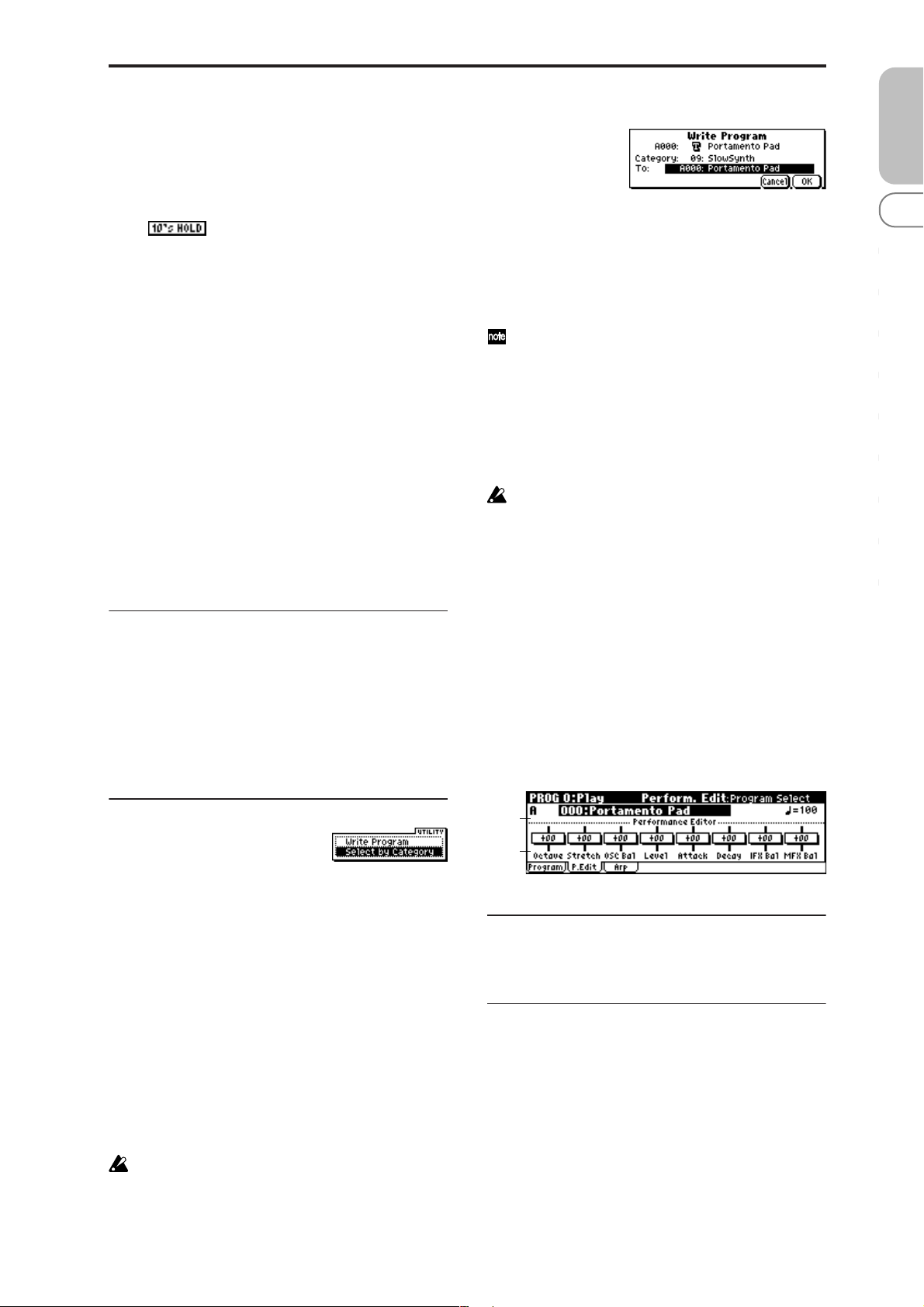
1 Select “Write Program” to access the dialog box.
2 The upper line shows the bank, program number and
program name.
3 In “Category,” specify the category of the program that
you are writing.
The category selected here can be used to find this program when selecting a program in Program, Combination, Multi.
With the factory settings, the program categories have
been given the names of instruments etc., but you can
use “Category Name Prog.00–07, 08–15” (GLOBAL 3–
1/2) to modify these category names.
4 In “To” to specify the writing destination.
X50: You can use the PROG BANK [A]–[D] buttons to
select a bank. You can also use the numeric buttons [0]–[9]
and [ENTER] button to select a program number.
You can’t write to bank G or g(d). If you’ve edited a
program from bank G or g(d) and want to write it,
you’ll need to write it to a bank other than the GM
bank.
5 If you want to change the program name, select the writ-
ing destination, press the center of the ClickPoint to
access the text dialog box, and enter a name. (☞OG X50:
p.112, microX: p.114)
6 To write the program, press the [MENU/OK] button. To
cancel, press the [EXIT/CANCEL] button.
Select by Category
Here you can select a program by category. (☞p.2)
PROG
0
123456789
microX: This area shows the functions that are assigned to
the REALTIME CONTROLS B-mode [ASSIGNABLE 1]–
[ASSIGNABLE 4] knobs.
■ 0–1: UTILITY
Use the following procedure to select the desired utility.
1 Press the [UTILITY] button to access the utility menu.
2 Use the ClickPoint to select the utility that you want to
execute.
3 Press the center of the ClickPoint to access the dialog box.
X50: Utilities up to number 10 can also be selected by hold-
ing down the [ENTER] button and pressing the corresponding numeric button [0]–[9] to access the dialog box.
Write Program
If you wish to save a program, be sure to write it into the
memory of the X50/microX.
An edited program cannot be recovered if you do not write
it to memory before turning off the power or selecting
another program.
If you want to write a program, you must first turn off
the memory protect setting in Global mode. (☞p.79
GLOBAL 0–2b: Memory Protect)
0–2: P.Edit (Performance Editor)
0–2a
0–2b
0–2a: Bank, Program Select, (Tempo)
Select a program. The bank, number, and name of the program will be displayed (☞p.1). “ ” sets the tempo.
0–2b: Performance Editor
The Performance Editor lets you edit major program parameters without moving to the PROG 1–9 Ed (Edit) pages.
This edits multiple program parameters within the currently
selected program, allowing you to make broad adjustments
easily.
You can use the Performance Editor when you wish to
adjust the depth of effects etc. while you are playing, or to
make the initial rough settings to begin the process of creating a new sound.
Editing that you do here will affect the values of the program parameters in the edit buffer.
If you wish to keep the results of your editing, you must
write (save) the program (☞OG p.45).
3
Page 11
Editing done using the Performance Editor will occur
within the range of the corresponding parameter. If
after using the Performance Editor to modify a value,
you move to another page or mode and then return, the
sound will remain in its edited state but the value
shown in the LCD screen by the Performance Editor
will be +00. You may do further editing from this state
if you wish.
Since editing done using the Performance Editor is not
as detailed as conventional editing, the balance
between parameters may be lost. If this occurs, use 1:
Ed–Basic–9: Ed–MasterFX to make fine adjustments.
If the MIDI Filter “Exclusive” (GLOBAL 1–1b) setting is
checked, MIDI exclusive parameter changes will be
transmitted whenever you operate the Performance
Editor. If these messages are received by an instrument
whose “Exclusive” setting is checked, the Performance
Editor on that instrument corresponding to the received
message will be modified.
Octave [–03...+00...+03]
An adjustment of +01 will raise the pitch one octave.
An adjustment of –01 will lower the pitch one octave.
This setting cannot adjust the pitch higher than 4' (feet) or
lower than 32' (feet).
Stretch (Pitch Stretch) [–12...+00...+12]
This simultaneously adjusts the Transpose and Tune of the
oscillator. This lets you produce a variety of tonal changes
and variations without loosing the character of the original
sound.
At the +00 setting, the value of the program parameters will
be unchanged.
An adjustment of +01 will lower the Transpose value by 1,
and simultaneously raise the Tune value by 100.
An adjustment of –01 will raise the Transpose value by 1,
and simultaneously lower the Tune value by 100.
However, it is not possible for the Transpose value to exceed
the range of ±12, nor the Tune value to exceed the range of
±1200.
OSC Bal (OSC Balance) [–10…+00…+10]
This adjusts the level balance between oscillators 1 and 2.
At the +00 setting, the value of the program parameters will
be unchanged.
Positive (+), settings will lower the oscillator 2 level.
With an adjustment of +10, the oscillator 2 level will be 0.
The oscillator 1 level will not change.
Negative (–) settings will lower the oscillator 1 level.
With an adjustment of –10, the oscillator 1 level will be 0.
The oscillator 2 level will not change.
For programs whose “Mode (Oscillator Mode)” (1–1a)
setting is Single, oscillator 2 will not sound. Only the
level of oscillator 1 will change. For a Drums program,
this performance editor will have no effect.
Level (Amp Level) [–10…+00…+10]
This adjusts the amp level.
With an adjustment of +00, the value of the program parameters will be unchanged.
Positive (+) settings will increase the amp level above the
value that was set.
With an adjustment of +10, the amp level will be 127 (maximum).
Negative (–) settings will lower the amp level below the
value that was set.
With an adjustment of –10, the amp level will be 0.
Attack (Attack Time) [–10…+00…+10]
This adjusts the attack times of the filter EG and amp EG.
With an adjustment of +00, the value of the program parameters will be unchanged.
Positive (+) settings will lengthen the attack times beyond
the values that were set.
With an adjustment of +10, the attack times will be 90.
Negative (–) settings will shorten the attack times.
With an adjustment of –10, the attack times will be 0.
When you modify “Attack Time,” the EG Start Level,
Attack Level, Start Level Modulation, and Attack Time
Modulation of the amp EG will also be adjusted simultaneously, to allow the maximum effect to be obtained.
Decay (Decay Time) [–10…+00…+10]
This adjusts the Decay Time and Slope Time of the filter EG
and amp EG.
With an adjustment of +00, the value of the program parameters will be unchanged.
Positive (+) settings will lengthen the Decay T ime and Slope
Time beyond the values that were set. With an adjustment of
+10, the times will be 99.
Negative (–) settings will shorten the Decay Time and Slope
Time. With an adjustment of –10, the times will be 0.
IFX Bal (IFX Balance) [–10…+00…+10]
This adjusts the “W/D(Wet/Dry)” setting of the insertion
effect.
With an adjustment of +00, the value of the program parameters will be unchanged.
Positive (+) settings will raise the Wet level above the program setting, and lower the Dry level. With an adjustment of
+10, the setting will be “Wet” - the effected signal only.
Negative (–) settings will lower the Wet level below the pro-
gram setting, and raise the Dry level. With an adjustment of
–10, the setting will be “Dry” - the signal is unaffected.
MFX Bal (MFX Balance) [–10…+00…+10]
This adjusts the master effect “Rtn1 (Return1)” and “Rtn2
(Return2)” (9–1a) settings as a whole.
With an adjustment of +00, the value of the program parameters will be unchanged.
Positive (+) settings will raise the return levels above the
program setting.
With an adjustment of +10, the setting will be 127 (maximum).
Negative (–) settings will lower the return levels below the
program setting.
With an adjustment of –10, the setting will be 0.
Octave Octave of OSC 1 and 2
Stretch Transpose and Tune of OSC 1 and 2
OSC Bal High Level and Low Level of OSC1 and 2
Level Amp1 Level, Amp2 Level
Attack Amp EG Attack Time, Start Level, Attack Level,
Level Modulation S, Time Modulation A of Amp 1
and 2, and Filter EG Attack Time of Filter 1 and 2
Decay AmpEG Decay Time, Slope Time of Amp 1 and 2,
Filter EG Decay Time and Slope Time of Filter 1
and 2
IFX Bal W/D (Wet/Dry) balance of the IFX effect
MFX Bal Master Effect RTN1, 2 (Return1, 2)
■ 0–2: UTILITY
☞ “Write Program,” “Select by Category” (0–1)
4
Page 12
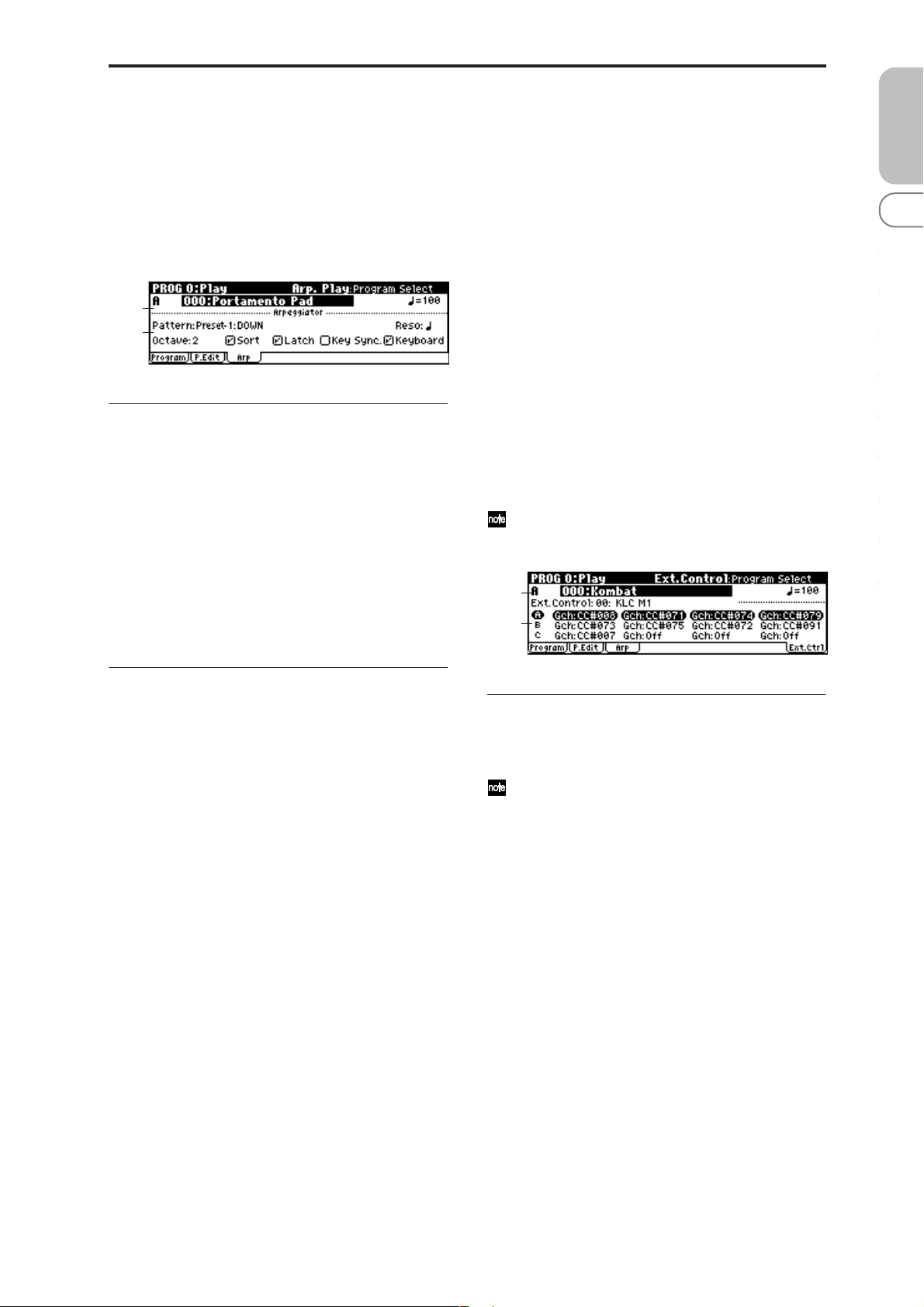
0–3: Arp (Arp. Play)
While arpeggiator parameters are for the most part edited in
PROG 7: Ed–Arp/Ctrls, Some major parameters can be
edited here as well. When you are playing in PROG 0: Play,
you can edit the arpeggiator in realtime, such as changing
the arpeggio pattern etc.
You can also use the REALTIME CONTROLS C-mode [ARPGATE], [ARP-LENGTH], [ARP-VELOCITY], and [TEMPO]
knobs to edit the arpeggio in realtime (☞OG p.91).
0–2a
0–3a
0–3a: Arpeggiator
Pattern [Preset-0...Preset-4, U000..U250]
Reso (Resolution) [ , , , , , ]
Octave [1, 2, 3, 4]
Sort [Off, On]
Latch [Off, On]
Key Sync. [Off, On]
Keyboard [Off, On]
Make settings for the program arpeggiator (☞“PROG: Ed–
Arp/Ctrls”). These parameters can also be set from 7: Ed–
Arp/Ctrls Setup page (☞7–1a).
microX: 0–4: Ext. Control
External control lets you use the REALTIME CONTROLS
knobs to control an external MIDI device. You can assign a
MIDI control change and MIDI channel to each of the four
knobs, and switch between three such settings (A, B, C) to
control your external device. One set lets you transmit a
total of twelve (4 × 3) different MIDI control changes. These
are called “external control sets,” and you can choose from
64 such sets.
For example you can use this to control parameters such as
level or pan on your DAW (digital audio workstation), or filter or envelope on your software synthesizer . Simply switch
between external control sets to choose the parameters you
want to control.
The external control function is independent of programs or
combinations. When you press the [EXT. CONTROLLER]
button to turn this function on (the LED will light), the external control set you’ve selected will not change even if you
change programs or switch to Combination mode or Multi
mode. This means that you can choose different sounds
without affecting how you’re controlling your external MIDI
device. Conversely , you can switch to other types of external
MIDI control without changing programs.
This page only displays the settings that are assigned to
knob sets A, B, and C. Use Global mode to make external control assignments.
0–2a
0–4a
PROG
0
123456789
■ 0–3: UTILITY
☞ “Write Program,” “Select by Category” (0–1)
0–4a: External Control
Ext. Control (Setup Select) [00...63]
Selects an external control set.
This setting is not written (saved) in the program.
Select [A, B, C]
Shows the settings assigned to each knob of the external
control set. The currently-enabled set is highlighted. Use the
[SELECT] button to switch between groups (A, B, C).
MIDI Channel [01...16, Gch]
Indicates the MIDI channel
Gch: The message will be transmitted on the global MIDI
channel you specify in Global mode. The channel of all
knobs that are set to Gch can be changed simply by changing the global MIDI channel setting, instead of having to
change the channel of each knob individually.
CC# Assign [Off, 000...119]
Indicates the MIDI control change number transmitted by
the knob.
5
Page 13

PROG 1: Ed–Basic
Here you can make basic settings for the oscillator(s).
1–1: Basic (Prog Basic)
1–1a
1–1b
1–1c
1–1a: Oscillator
Mode (Oscillator Mode)
[Single, Double, Drums]
Specifies the basic program type; whether it will use one or
two oscillators, or a drum kit.
Single: The program will use one oscillator (Oscillator 1,
Filter 1, Amplifier 1). In this case the program will have a
maximum of 62-note polyphony.
Double: The program will use two oscillators (Oscillator 1/
2, Filter 1/2, Amplifier 1/2). Allowing you to create more
complex sounds. In this case the program will have a 31-
note maximum polyphony.
Drums: The program will use one oscillator (as when Sin-
gle is selected), but Oscillator 1 will be assigned a drum kit
instead of a multisample. In this case the program will have
a maximum of 62-notes of polyphony.
On (checked): When the same note is played repeatedly, the
previous note will be silenced before the next note is
sounded, so that the notes do not overlap.
Legato [Off, On]
This is available when the “Mode (Voice Assign Mode)” setting is set to Mono.
On (checked): Legato is on. When multiple note-on messages occur, the first note-on will retrigger the sound, and
the second and subsequent note-ons will not retrigger.
When legato is on, multiple note-on message will not retrigger the voice. If one note is already on and another note is
turned on, the oscillator sound, envelope, and LFO will not
be reset, and only the pitch of the oscillator will be updated.
This setting is effective for wind instrument sounds and
analog synth-type sounds.
Off (unchecked): Legato is off. Notes will always be retriggered when note-on occurs.
When legato is off, multiple note-on’s will retrigger the
voice at each note-on. The oscillator sound, envelope, and
LFO will be reset (and retriggered) according to the settings
of the program.
If “Legato” is checked, certain multisamples or keyboard locations may produce an incorrect pitch.
Priority [Low, High, Last]
This parameter is valid when “Mode (Voice Assign Mode)”
is set to Mono.
It specifies which note will be given priority to play when
two or more notes are played simultaneously.
Low: Lowest note will take priority.
High: Highest note will take priority.
Last: Last note will take priority.
1–1c: Scale
1–1b: Voice Assign
Mode (Voice Assign Mode) [Poly, Mono]
Poly: The program will play polyphonically, allowing you
play chords.
Mono: The program will play monophonically, producing
only one note at a time.
Hold [Off, On]
On (checked): Hold is On. Even when you take your finger
off of the key, the note will continue sounding as if it continued to be held. Unless the “Amp1 EG”, “Amp2 EG” (6–3, 6–
6) “S (Sustain Level)” is set to 0, the sound will continue
playing.
This is ideal for playing drum sounds, If you set “Mode
(Oscillator Mode)” (1–1a) to Drums, you should normally
turn Hold On.
Off (unchecked): Hold is Off. Except for drum programs,
you should normally set Hold Off.
If you turn “Hold” On for a drum program, keys of the
selected drum kit whose “Enable Note Off” parameter
(GLOBAL 4–3a) is unchecked will be set to Hold On.
Keys that are checked will be set to Hold Off. If you
select Hold Off, the keys will be set to Hold Off regard-
less of their “Enable Note Off” setting.
Single Trigger [Off, On]
This is available when the “Mode (Voice Assign Mode)” setting is set to Poly.
Type (Scale Type)
[Equal Temperament…User Octave 15]
Indicates the basic scale for the internal tone generator.
Equal Temperament: This is the most widely used scale,
where each semitone step is spaced at equal pitch intervals.
Pure Major: In this temperament, major chords of the
selected tonic will be perfectly in tune.
Pure Minor: In this temperament, minor chords of the
selected tonic will be perfectly in tune.
Arabic: This scale includes the quarter-tone scale used in
Arabic music.
Pythagoras: This scale is based on ancient Greek musical
theory, and is especially effective for playing melodies.
Werkmeister (Werkmeister III): This is an equal tempered
scale that was used since the later Baroque period.
Kirnberger (Kirnberger III): This scale was created in the
18th century, and is used mainly to tune harpsichords.
Slendro: This is an Indonesian gamelan scale in which an
octave consists of five notes.
When “Key” is set to C, use the C, D, F, G and A notes.
(Other keys will sound equal-tempered pitches.)
Pelog: This is an Indonesian gamelan scale in which an
octave consists of seven notes.
When “Key” is set to C, use the white keys. (The black keys
will sound the equal tempered pitches.)
Stretch: This tuning is used for acoustic pianos.
6
Page 14

User All Notes: This is the full-range scale (C–1 – G9) that is
specified in “User All Notes Scale” (GLOBAL 2–2a).
User Octave 00–15: These are the single-octave scales that
are specified in “User Octave Scale” (GLOBAL 2–1a).
Key [C…B]
Indicates the tonic note of the specified scale.
This setting is not valid for Equal Temperament, Stretch,
and User All Notes Scale.
Random [0…7]
As this value is increased, a greater variance will be applied
to the pitch when each note is sounded. Normally you will
set this to 0. This parameter is used when simulating instruments that have natural instability in pitch, such as tapemechanism organs or acoustic instruments.
If a scale other than Equal T emperament is selected, the
combination of the selected scale and the “Key” setting
may skew the tuning of the base key (for example
A=440 Hz). If this occurs, use “Master T une” (GLOBAL
0–1a) to correct the pitch.
■ 1–1: UTILITY
☞ “Write Program” (0–1)
For details on how to select the desired utility function, refer
to “PROG 0–1: UTILITY.”
1–2: OSC1
The multisample(s) (waveform) or drum kit on which the
program will be based can be selected here for oscillator 1
and/or oscillator 2.
You can use the following multisamples.
X50: 470 different multisamples, 49 different drum kits.
microX: 642 different multisamples, 49 different drum
kits.
The following illustration shows a LCD screen where
“Mode (Oscillator Mode)” (1–1a) has been set to Double. If
this is set to Single, the OSC2 page parameter will not
appear and cannot be set.
1–2a
1–2b
1–2c
The following illustration shows the display when “Mode
(Oscillator Mode)” (1–1a) has been set to Drums.
1–2d
PROG
0
123456789
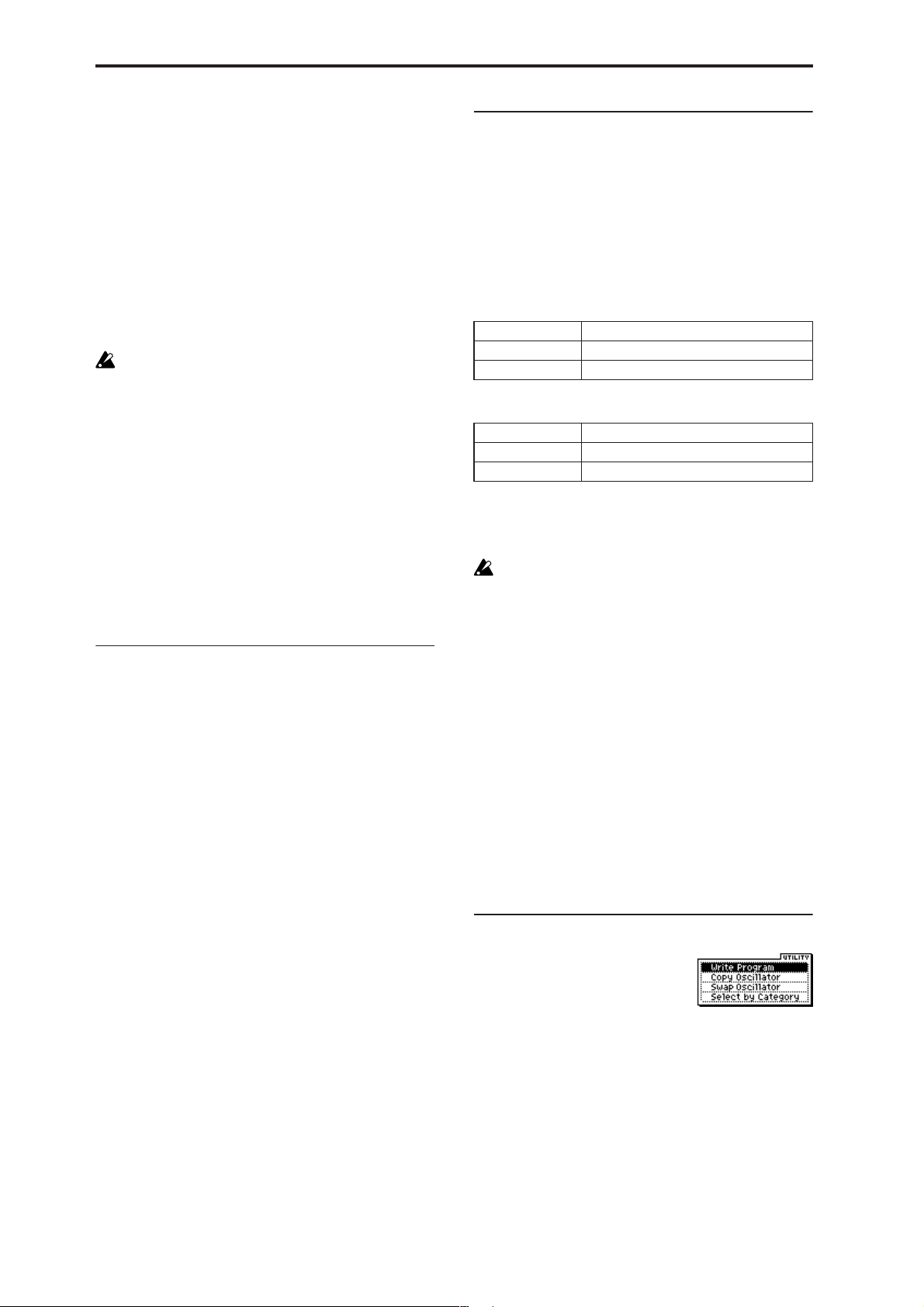
Copy Oscillator
This function copies oscillator settings to the currently
selected program.
1 Select “Copy Oscillator” to access the dialog box.
2 In “From,” select the oscillator that you wish to copy and
the copy source program.
X50: You can use the PROG BANK [A]–[GM] buttons to
select a bank. You can also use the numeric buttons [0]–[9]
and [ENTER] button to select a program number.
3 In “To,” select the copy destination oscillator.
4 To execute the Copy Oscillator operation, press [MENU/
OK] button. To cancel, press the [EXIT/CANCEL] button.
Swap Oscillator
This command exchanges the settings of oscillators 1 and 2.
1 Select “Swap Oscillator” to access the dialog box.
2 To execute the Swap Oscillator operation, press [MENU/
OK] button. To cancel, press the [EXIT/CANCEL] button.
This can be selected only if “Mode (Oscillator Mode)”
(1–1a) is Double.
1–2a: OSC1 Multisample
Velocity SW L→H [001...127]
The oscillator 1 High and Low multisamples that you specify in “High, Low” (1–2b) will be switched at the velocity
value that you specify here. Notes played with a velocity
stronger than this value will be sounded by the High multisample.
1–2b: High, Low
Here you can select a multisample.
You can select different multisamples for High and Low , and
use velocity to switch between the two multisamples. Start
Offset, Reverse, and Level can be adjusted independently
for the High and Low multisamples.
High:
High Multisample X50: [000...469]
microX: [000...641]
Specifies the bank and multisample number of the High
multisample. The multisample you select here will sounded
by velocities greater than the value of the “Velocity SW
L→H” (1–2a) parameter. If you do not wish to use velocity
switching, set the value to 001, and select only the High
multisample.
Each multisample has an upper limit, and may not produce sound when played above that limit.
S.Ofs (High Start Offset) [Off, On]
This specifies the point at which the multisample will begin
sounding. For some multisamples this parameter will have
no effect.
7
Page 15
On (checked): The sound will start from the start offset location that is pre-determined for each multisample.
Off (unchecked): The sound will start from the beginning of
the multisample waveform.
Rev (High Reverse) [Off, On]
The multisample will be played in reverse. If the multisample was originally set to reverse, it will playback without
change.
On (checked): The multisample will playback in reverse.
Off (unchecked): The multisample will playback normally.
Level (High Level) [000...127]
Specifies the level of the multisample.
Depending on the multisample, high settings of this
parameter may cause the sound to distort when a chord
is played. If this occurs, lower the level.
Low:
Specifies the OSC1 Low multisample.
The Low multisample will sound when the velocity is less
than the “Velocity SW L→H” (1–2a) setting.
1–2d: OSC1 Drum Kit
Drum Kit
X50: [00(INT)...15(INT), 16(User)...39(User),
40(GM)...48(GM)]
microX: [00(INT)...31(INT),
32(User)...39(User), 40(GM)...48(GM)]
Select a drum kit.
X50
00 (INT)–15 (INT) Preload drum kits.
16 (User)–39 (User) for user drum kits
40 (GM)–48 (GM) ROM preset drum kits compatible with GM2.
microX
00 (INT)–31 (INT) Preload drum kits.
32 (User)–39 (User) for user drum kits
40 (GM)–48 (GM) ROM preset drum kits compatible with GM2.
Low Multisample X50: [000...469]
microX: [000...641]
S.Ofs (Low Start Offset) [Off, On]
Rev (Low Reverse) [Off, On]
Level (Low Level) [000...127]
☞ Refer to the corresponding item in “High.”
1–2c: Octave, Transpose , Tune, Delay
Octave [–2[32’], –1[16’], +0[8’], +1[4’]]
Adjusts the pitch in octave units. The normal octave of the
multisample is 8' (feet).
Transpose [–12…+12]
Adjusts the pitch in semitone steps over a range of ±1
octave.
Tune [–1200…+1200]
Adjusts the pitch of the sample in one-cent steps (a semitone
is 100 cents) over a range of ±1 octave.
Delay [0000ms…5000ms, KeyOff ]
Specifies a delay time from note-on until the note will
sound.
With a setting of KeyOff, the sound will begin when noteoff occurs. This is used to create sounds such as the “click”
that is heard when a harpsichord note is released. In this
case, set the “Amp1 EG”, “Amp2 EG” (6–3, 6–6) “S (Sustain
Level)” parameter to 0.
Octave [–2[32’], –1[16’], +0[8’], +1[4’]]
Adjusts the pitch in octave units. When using a drum kit, set
the Octave to +8'.
When editing a drum program, you must set this
parameter to +8'. With other settings, the sounds of the
drum kit will be assigned to the wrong notes of the keyboard.
Transpose [–12…+12]
This adjusts the location of the instruments in the selected
drum kit. Unless you need to change this, leave it at 0.
Tune [–1200…+1200]
This adjusts the pitch in one-cent units.
The pitch of each drum kit can be adjusted in GLOBAL 4:
DKit.
Delay [0000ms…5000ms, KeyOff ]
This specifies a delay time from note-on until the sound will
begin.
With a setting of KeyOff, the sound will begin when noteoff occurs. In this case, set the “Amp1 EG” parameter “S
(Sustain Level)” (6–3a) to 0.
■ 1–2: UTILITY
☞ “Write Program” (0–1), “Copy Oscillator,” “Swap Oscilla-
tor” (1–1)
For details on how to select the desired utility function, refer
to “PROG 0–1: UTILITY.”
8
Page 16
Select by Category
Selects multisamples by category.
For the procedure, refer to “Select by Category” (☞p.2).
This command is valid if “Mode (Oscillator Mode)” (1–
1a) is set to Single or Double, and you have selected
the 1–2b: High, Low parameter.
1–3: OSC2
This will appear when “Mode (Oscillator Mode)” (1–1a) is
set to Double.
For details on the settings and function of the parameter,
refer to “1–2: OSC1.”
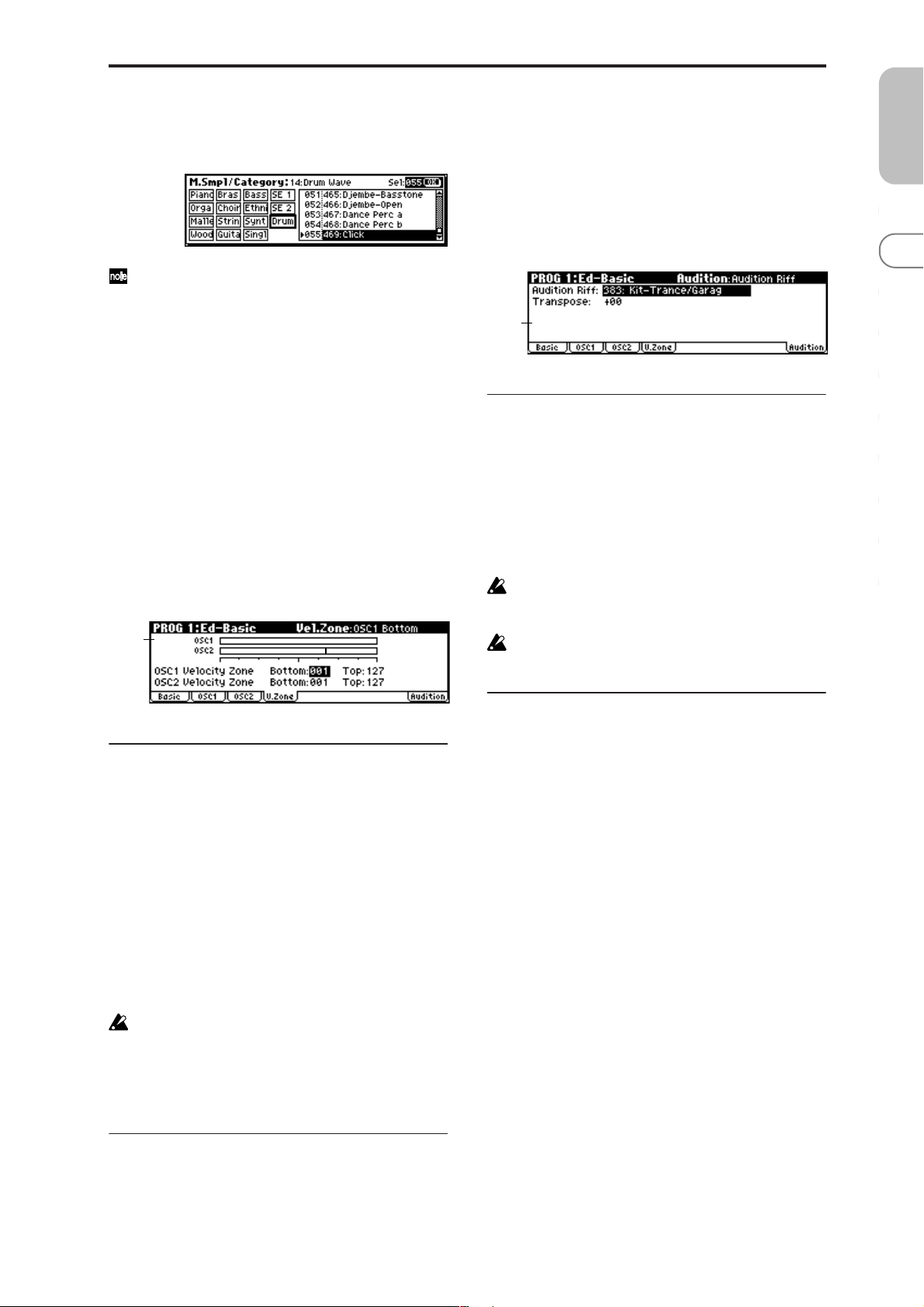
1–4: V.Zone (Velocity Zone)
Specifies the range of velocities that will sound oscillator 1
and 2. By using these settings in conjunction with the
“V elocity SW L→H” (1–2a) setting of each oscillator, you can
specify the velocity ranges for the High and Low multisamples or drum kits.
1–4a
1–5: Audition
When selecting preloaded programs, you can play back a
pre-specified riff (phrase) that is suitable for the sound of
that program. This is called the Audition function.
When you press the [AUDITION] button to turn it on, the
audition riff will play back repeatedly.
Here you can select the audition riff and specify the transposition.
1–5a
1–5a: Audition Riff, Transpose
Audition Riff [000: Off...383: name]
Selects the audition riff. The X50/microX contains 383 audition riffs suitable for a variety of instruments and musical
genres.
With a setting of 000: Off, no riff will be played.
Transpose [–24...+24]
Adjusts the pitch of the audition riff in semitone steps.
It is not possible to change the playback tempo of the
audition riff. Nor is it possible to set the arpeggiator
tempo while the audition riff is playing.
The arpeggiator will be turned off while the audition
riff is playing.
PROG
0
123456789
1–4a: OSC 1/2 Velocity Zone
OSC1 Bottom [001...127]
Sets the minimum velocity value that will sound oscillator 1.
OSC1 T op [001...127]
Sets the maximum velocity value that will sound oscillator
1.
OSC2 Bottom [001...127]
Sets the minimum velocity value that will sound oscillator 2.
OSC2 T op [001...127]
Sets the maximum velocity value that will sound oscillator
2.
It is not possible to set the Bottom Velocity greater than
the Top Velocity, nor the Top Velocity less than the Bottom Velocity.
X50: You can also input a value by playing a note on the
keyboard while you hold down the [ENTER] button.
■ 1–4: UTILITY
☞ “Write Program” (0–1), “Copy Oscillator,” “Swap Oscilla-
tor” (1–1)
■ 1–5: UTILITY
☞ “Write Program” (0–1)
9
Page 17
PROG 2: Ed–Pitch
Here you can make pitch modulation settings for oscillators
1 and 2.
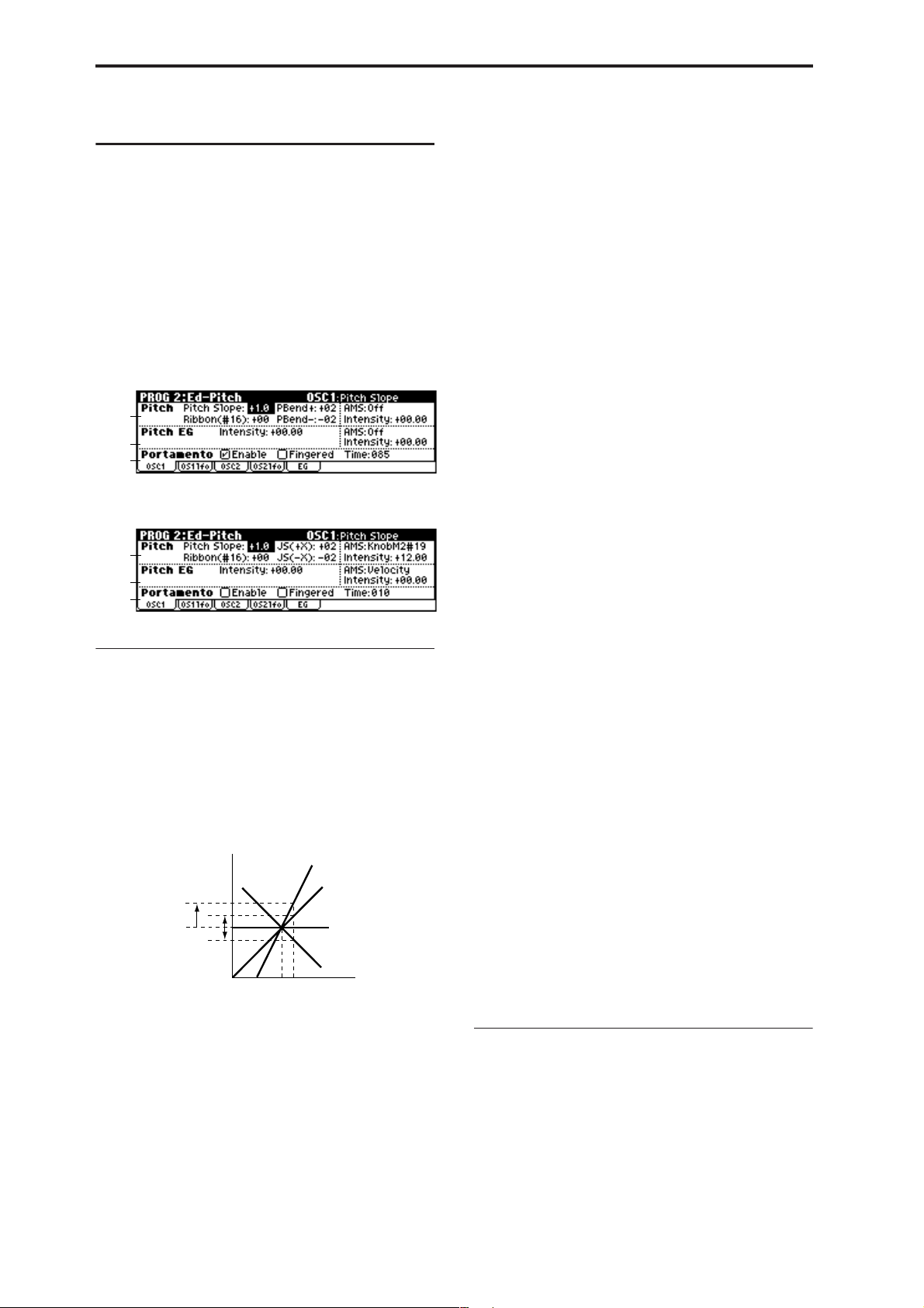
2–1: OSC1
Specifies how the key position (on the keyboard) will affect
the pitch of oscillator 1, and selects the controller that will
modify the pitch and the depth of this effect. Here you can
also specify the amount of pitch change caused by the pitch
EG, and set the portamento mode and on/off status.
X50
2–1a
2–1b
2–1c
microX
2–1a
2–1b
2–1c
2–1a: Pitch
Pitch Slope [–1.0…+2.0]
Normally you will leave this at +1.0.
Positive (+) values will cause the pitch to rise as you play
higher on the keyboard, and negative (–) values will cause
the pitch to fall as you play higher on the keyboard.
With a value of 0, there will be no change in pitch, and the
C4 pitch will sound regardless of the keyboard location you
play.
How the Pitch Slope and pitch are related
Pitch
2oct
1oct
1oct
Ribbon (#16) [–12…+12]
Specifies in semitone units how the pitch will change when
CC#16 is received (or when the ribbon controller is pressed
on an instrument, such as the TRITON Extreme, connected
via the MIDI IN connector).
12 half-steps equal one octave. With positive (+) values, the
pitch will rise when you press the right half of a ribbon controller. With negative (–) values, the pitch will fall.
For example, with a setting of +12, pressing the far right
edge of the ribbon controller will raise the pitch one octave.
With a setting of –12, pressing the far right edge of the ribbon controller will lower the pitch one octave.
C4 C5
+2
+1
0
–1
Key
At the center of the ribbon controller, the original pitch will
remain, so you can use this in conjunction with pressing the
ribbon at its right edge to simulate the “hammering-on”
techniques used by guitarists.
X50: PBend + [–60…+12]
Specifies the amount of pitch change (in semitones) that will
occur when you move the [PITCH] wheel up from the center
position.
For example if this is set to +12, moving the [PITCH] wheel
up from the center position will raise the pitch by one
octave.
microX: JS (+X) [–60…+12]
Specifies how the pitch will change when the joystick is
moved all the way to the right.
A setting of 12 produces 1 octave of change.
For example, if you set this to +12 and move the joystick all
the way to the right, the pitch will rise one octave above the
original pitch.
X50: PBend – [–60…+12]
Specifies the amount of pitch change (in semitones) that will
occur when you move the [PITCH] wheel down from the
center position.
For example if this is set to +12, moving the [PITCH] wheel
down from the center position will raise the pitch by one
octave.
microX: JS (–X) [–60…+12]
Specifies how the pitch will change when the joystick is
moved all the way to the left.
A setting of 12 produces 1 octave of change.
For example, if you set this to –60 and move the joystick all
the way to the left, the pitch will fall five octaves below the
original pitch. This can be used to simulate the downward
swoops that a guitarist produces using the tremolo arm.
AMS (Pitch AMS) [Off, (FEG, AEG, EXT )]
Selects the source that will modulate the pitch of oscillator 1
(☞p.152 “AMS List”).
Intensity (AMS Intensity) [–12.00…+12.00]
Specifies the depth and direction of the effect produced by
“AMS (Pitch AMS).”
With a setting of 0, no modulation will be applied. With a
setting of 12.00, the pitch will change up to one octave.
For example if “AMS (Pitch AMS)” is set to Pedal #04, Global 0–3a “Foot Pedal Assign” is set to Foot Pedal (CC#04),
and you advance a foot pedal connected to the ASSIGNABLE PEDAL jack, the pitch will rise if you have assigned a
positive (+) value here, or fall if you have assigned a negative (–) value. The maximum range is one octave. (☞p.154)
2–1b: Pitch EG
Intensity [–12.00…+12.00]
Specifies the depth and direction of the modulation that the
pitch EG specified in “EG (Pitch EG)” (2–5) page will apply
to the pitch.
With a setting of 12.00, the pitch will change a maximum of
±1 octave.
10
Page 18

AMS (Pitch EG AMS) [Off, (KT, EXT)]
Selects the source that will control the pitch modulation
applied by the pitch EG (☞p.152 “AMS List”).
Intensity (AMS Intensity) [–12.00…+12.00]
Specifies the depth and direction of the effect that “AMS
(Pitch EG AMS)” will have.
For example, if you set “AMS (Pitch EG AMS)” to Velocity
and set this value to +12.00, the velocity will control the
range of pitch change produced by the pitch EG in a range
of ±1 octave (☞p.154). As you play more softly, the pitch
change will draw closer to the pitch EG levels.
Pitch change (level)
Note-on
Note-off
Note-on
Note-off
Note-on
Note-off
2–2: OS1lfo (OSC1 LFO)
Specifies the amount of pitch change produced by LFO1 and
LFO2 for oscillator 1.
X50
2–2a
microX
2–2a
PROG
0
123456789
Softly played
(Intensity (Pitch EG) setting)
“Intensity” and “AMS (Pitch EG AMS)” will be
summed to determine the depth and direction of the
pitch modulation applied by the pitch EG.
Strongly played with
a positive (+) value
Strongly played with a
negative (–) value
2–1c: Portamento
This turns the portamento effect (smooth change in pitch
from one note to the next) on/off, and specifies how it will
be applied.
If you set Global 0–3a “Foot SW Assign” to Portamento SW
(CC#65) and turn a pedal switch connected to the ASSIGNABLE SWITCH jack on/off, the portamento effect will be
applied according to these settings.
(☞p.164 “Foot Switch Assign List” Portamento SW (CC#65))
X50: If [SW1] or [SW2] is set to Porta.SW (CC#65), using
SW1 or SW2 to turn portamento on/off will apply the settings you specify here.
(☞p.152 “AMS List,” ☞p.161 “SW1, SW2 Assign List” Prta.
SWCC#65)
Portamento will also be switched when CC#65 (Portamento SW) is received.
Enable (Porta. Enable) [Off, On]
On (checked): Portamento will be applied.
Off (unchecked): Portamento will not be applied.
Fingered (Porta. Fingered) [Off, On]
This parameter is available when “Enable (Porta. Enable)” is
checked.
On (checked): Portamento will be applied when you con-
tinue holding the previous note as you press the next note
(legato playing).
Off (unchecked): Portamento will always be applied,
regardless of how you play.
Time (Porta. Time) [000...127]
This parameter is available when “Enable (Porta. Enable)” is
checked.
This sets the portamento time. Increasing the value will produce a slower change in pitch.
2–2a: Pitch LFO1/2 Modulation
LFO1:
Intensity (LFO1 Intensity) [–12.00…+12.00]
Specifies the depth and direction of the pitch modulation
applied by the OSC 1 LFO1 settings you made in
“OS1LFO1” page (3–1).
With a setting of 12.00, a maximum of ±1 octave of pitch
modulation will be applied. Negative (–) values will invert
the LFO waveform.
X50: Mod.Whl Int. (LFO1 Mod.Whl+Int.)
[–12.00…+12.00]
Specifies the depth of pitch modulation that will be applied
by OSC1 LFO1 when you move the [MOD] up.
As you specify a higher value for this parameter, a greater
amount of pitch modulation will be applied by OSC1 LFO1
when you move the [MOD] wheel up (away from yourself).
With a setting of 12.00, a maximum of ±1 octave of pitch
modulation will be applied. Negative (–) values will invert
the polarity of the LFO.
microX: JS+Y Int. (LFO1 JS+Y Int.)
[–12.00…+12.00]
Specifies the depth and direction of the effect that joystick
movement in the +Y direction (up) will have on the pitch
modulation applied by the OSC1 LFO1.
As this value is increased, moving the joystick in the +Y
direction will cause the OSC1 LFO1 to produce deeper pitch
modulation. With a setting of 12.00 a maximum of ±1 octave
of pitch modulation will be applied. Negative (–) values
will invert the LFO waveform.
AMS (LFO1 AMS)
[Off, (PEG, FEG, AEG, KT, EXT)]
Indicates the source that will control the depth of pitch modulation produced by the OSC1 LFO1 (☞p.152 “AMS List”).
■ 2–1: UTILITY
☞ “Write Program” (0–1), “Copy Oscillator,” “Swap Oscilla-
tor” (1–1)
11
Page 19

Intensity (AMS Intensity) [–12.00…+12.00]
Specifies the depth and direction of the effect that “AMS
(LFO1 AMS)” will have.
With a setting of 0, modulation will not be applied. With a
setting of 12.00, the OSC1 LFO1 will apply a maximum of ±1
octave of pitch modulation. Negative (–) settings will invert
the LFO waveform.
For example if “AMS (LFO1 AMS)” is set to Pedal #04, Global 0–3a “Foot Pedal Assign” is set to Foot Pedal (CC#04),
and you advance a foot pedal connected to the ASSIGNABLE PEDAL jack, the pitch modulation produced by OSC1
LFO1 will be applied in the normal phase if you have
assigned a positive (+) value, or in the reverse phase if you
have assigned a negative (–) value.
The depth and direction of the pitch modulation produced by OSC1 LFO1 depends on the sum of the settings
X50:
for “Intensity (LFO1 Intensity),”
(LFO1 MWheel+Int.)”/
Int.),” and “AMS (LFO1 AMS). (
microX:
“M.Whl+Int.”
“JS+Y Int. (LFO1 JS+Y
☞
p.154)
LFO2:
Intensity (LFO2 Intensity) [–12.00…+12.00]
X50: Mod.Whl Int. (LFO2 Mod.Whl Int.)
[–12.00…+12.00]
microX: JS+Y Int. (LFO2 JS+Y Int.)
[–12.00…+12.00]
AMS (LFO2 AMS)
[Off, (PEG, FEG, AEG, KT, EXT)]
Intensity (AMS Intensity) [–12.00…+12.00]
Refer to the preceding section “LFO1.”
2–5: EG (Pitch EG)
Here you can make settings for the pitch EG, which creates
time-variant changes in the pitch of oscillators 1 and 2.
The depth of pitch change produced by these EG settings on
oscillator 1 (2) is adjusted by “Pitch EG” (2–1b, 2–3).
2–5a
2–5b
2–5c
2–5a: Pitch EG
These settings specify how the pitch will change over time.
Time-varying pitch settings (when Pitch EG Intensity = +12.00)
+99 = approximately 1 octave
Note-on
0 = pitch when
key is held
(sustained)
Start Level
–99 = approximately 1 octave
L (Level parameters):
These parameters specify the amount of pitch change.
The actual amount of pitch change will depend on the
“Pitch EG” (2–1b, 2–3) parameter “Intensity.”
For example with an “Intensity” setting of +12.00, a “Level”
setting of +99 would raise the pitch one octave, and a
“Level” setting of –99 would lower the pitch one octave.
Attack
Time
Attack Level
Decay
Time
Note-off
Release Time
Time
Release Level
■ 2–2: UTILITY
☞ “Write Program” (0–1), “Copy Oscillator,” “Swap Oscilla-
tor” (1–1)
2–3: OSC2
Specifies how the key position (on the keyboard) will affect
the pitch of oscillator 2, and selects the controller that will
affect the pitch and specify the depth of control. Here you
can also specify the amount of pitch change produced by the
pitch EG, and set the portamento mode and on/off status.
For details on each parameter, refer to the preceding “2–1:
OSC1.”
2–4: OS2lfo (OSC2 LFO)
Specifies the amount of pitch change produced by LFO1 and
LFO2 for oscillator 2. For an explanation of each parameter,
refer to the preceding “2–2: OS1lfo.”
S (Start Level) [–99…+99]
Specifies the amount of pitch change at note-on.
A (Attack Level) [–99…+99]
Specifies the amount of pitch change when the attack time
has elapsed.
R (Release Level) [–99…+99]
Specifies the amount of pitch change when the release time
has elapsed.
T (Time parameters):
These parameters specify the length of time over which the
pitch change will occur.
A (Attack Time) [0…99]
Specifies the time over which the pitch will change from
note-on until it reaches the pitch specified as the attack level.
D (Decay Time) [0…99]
Specifies the time over which the pitch will change after
reaching the attack level until it reaches the normal pitch.
R (Release Time) [0…99]
Specifies the time over which the pitch will change from
note-off until it reaches the pitch specified as the release
level.
12
Page 20
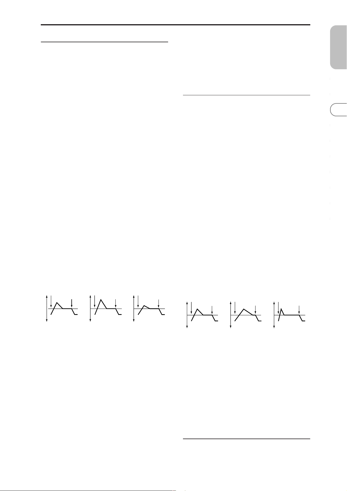
2–5b: Level Mod. (Level Modulation)
These settings allow the pitch EG “L (Level parameters)” to
be controlled by alternate modulation.
AMS1 (Level Mod. AMS1) [Off, (KT, EXT)]
Selects the source that will control the pitch EG “L (Level
parameters)” (☞p.152 “AMS List”).
I (AMS1 Intensity) [–99…+99]
Specifies the depth and direction of the effect applied by
“AMS1 (Level Mod. AMS1).”
With a setting of 0, the levels specified by “Pitch EG” (2–5a)
will be used.
If “AMS1” is set to Velocity, increasing the absolute value of
“Intensity” will produce increasingly wider change in pitch
EG levels for strongly-played notes. The direction of the
change is specified by “S (AMS1 SW Start)” and “A (AMS1
SW Attack).” As you play more softly, the pitch change will
draw closer to the pitch EG levels.
X50: For example if “AMS1 (Level Mod. AMS1)” is set to
SW1 #80 and 7–3b: SW1/2 Assign “SW1” is set to SW1 Mod.
(CC#80), turning [SW1] on will change the Pitch EG “Level.”
Increasing the absolute value of “I (AMS1 Intensity)” will
produce a greater change in the pitch EG level when [SW1]
is turned on. The direction of the change is specified by “S
(AMS1 SW Start)” and “A (AMS1 SW Attack).” If [SW1] is
off, the levels specified by the pitch EG settings will be used.
microX: For example if “AMS1 (Level Mod. AMS1)” is set
to FootSW #82 and Global 0–3a “Foot SW Assign” is set to
Foot SW (CC#82), receiving CC#82 or turning on the pedal
switch will change the Pitch EG “Level.” Increasing the
absolute value of “I (AMS1 Intensity)” will produce a
greater change in the pitch EG level when the pedal switch
is turned on. The direction of the change is specified by “S
(AMS1 SW Start)” and “A (AMS1 SW Attack).” If the pedal
switch is off, the levels specified by the pitch EG settings will
be used.
Pitch EG change (level) (AMS=SW1/Velocity, Intensity= positive (+) value)
Note-on
Note-off
Note-on
Note-off
Note-on
Note-off
AMS2 (Level Mod. AMS2) [Off, (KT, EXT)]
I (AMS2 Intensity) [–99…+99]
S (AMS2 SW Start) [–, 0, +]
A (AMS2 SW Attack) [–, 0, +]
Refer to the preceding paragraphs “AMS1 (Level Mod.
AMS1)”–“A (AMS1 SW Attack).”
2–5c: Time Mod. (Time Modulation)
These parameters let you use alternate modulation to control the “T (Time parameters)” of the pitch EG.
AMS (Time Mod. AMS) [Off, (KT, EXT)]
Indicates the source that will control the “T (Time parameters)” of the pitch EG (☞p.152 “AMS List”).
I (AMS Intensity) [–99…+99]
Specifies the depth and direction of the effect that “AMS
(Time Mod. AMS)” will have.
With a setting of 0, the pitch EG times will be just as specified by the “Pitch EG” (2–5a) settings.
The alternate modulation value at the moment that the EG
reaches each point will determine the actual value of the EG
time that comes next.
For example, the decay time will be determined by the alternate modulation value at the moment that the attack level is
reached.
When this parameter is set to values of 16, 33, 49, 66, 82, or
99, the specified EG times will speed up as much as 2, 4, 8,
16, 32, or 64 times respectively (or slowed down to 1/2, 1/4,
1/8, 1/16, 1/32, or 1/64 of the original time).
For example if “AMS (Time Mod. AMS)” is set to Velocity,
increasing the absolute value of “I (AMS Intensity)” will
allow strongly-played notes to increase the changes in pitch
EG “T (Time parameters)” values. The direction of the change
is specified by “A (AMS SW Attack)” and “D (AMS SW
Decay).” As you play more softly, the pitch EG times will
more closely approach the actual settings of the pitch EG.
Pitch EG changes (Time) (AMS = Velocity, Intensity = positive (+) value)
Note-on
Note-off
Note-on
Note-off
Note-on
Note-off
PROG
0
123456789
A note played softly with “S”
set at 0, “A” set to +, and
SW1 turned off (the settings
of 2–5a: Pitch EG)
A note played strongly with
“S” set to 0, “A” set to +, and
SW1 turned on
A note played strongly with
“S” set to 0, “A” set to –, and
SW1 turned on
S (AMS1 SW Start) [–, 0, +]
Specifies the direction of change in “S (Start Level)” caused
by “AMS1 (Level Mod. AMS1).” If “I (AMS1 Intensity)” is a
positive (+) value, a setting of + will raise the EG level, and
a setting of – will decrease it. With a setting of 0 there will be
no change.
A (AMS1 SW Attack) [–, 0, +]
Specifies the direction of change in “A (Attack Level)”
caused by “AMS1 (Level Mod. AMS1).” If “I (AMS1 Intensity)” is a positive (+) value, a setting of + will raise the EG
level, and a setting of – will decrease it. With a setting of 0
there will be no change.
A note played softly with “A”
set to + and “D” set to +
(settings of 2–5a: Pitch EG)
A note played strongly with
“A” set to + and “D” set to +
A note played strongly with
“A” set to – and “D” set to –
A (AMS SW Attack) [–, 0, +]
Specifies the direction in which “AMS (Time Mod. AMS)”
will affect the “A (Attack Time).” With positive (+) values of
“I (AMS Intensity),” a setting of + will cause the time to be
lengthened, and a setting of – will cause the time to be shortened. With a setting of 0 there will be no change.
D (AMS SW Decay) [–, 0, +]
Specifies the direction in which “AMS (Time Mod. AMS)”
will affect the “D (Decay Time).” With positive (+) values of
“I (AMS Intensity),” a setting of + will cause the time to be
lengthened, and a setting of – will cause the time to be shortened. With a setting of 0 there will be no change.
■ 2–5: UTILITY
☞ “Write Program” (0–1), “Copy Oscillator,” “Swap Oscilla-
tor” (1–1)
13
Page 21
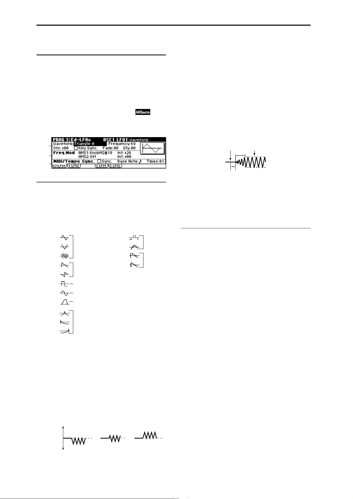
PROG 3: Ed–LFOs
Here you can make settings for the LFO that can be used to
cyclically modulate the Pitch, Filter, and Amp of oscillators 1
and 2. There are two LFO units for each oscillator.
By setting the LFO1 or LFO2 Intensity to a negative (–) value
for Pitch, Filter, or Amp, you can invert the LFO waveform.
Key Sync. [Off, On]
On (checked): Key Sync. will be On. The LFO will start each
time you play a note, and an independent LFO will operate
for each note.
Off (unchecked): Key Sync. will be Off, and the LFO effect
that was started by the first-played note will continue to be
applied to each newly-played note. (In this case, “Delay”
and “Fade” will be applied only to the LFO when it is first
started.)
3–1: OS1LFO1 (OSC1 LFO1)
Indicates settings for the “OSC1 LFO1,” which is the first
LFO that can be used for oscillator 1.
3–1a
3–1b
3–1c
3–1a: OSC1 LFO1
Waveform [Triangle 0…Random6 (Vect.)]
Selects the LFO waveform.
The numbers that appear at the right of some of the LFO
waveforms indicate the phase at which the waveform will
begin.
Triangle 0
Triangle 90
Triangle
Random
Saw 0
Saw 180
Square
Sine
Guitar
Exp.Triangle
Exp.Saw Down
Exp.Saw Up
Triangle wave
Phase will change
randomly at each key-in
Sawtooth down ↓
Square wave
Sine wave
Guitar vibrato
Frequency [00…99]
Sets the LFO frequency. A setting of 99 is the fastest.
Ofs (Offset) [–99…+99]
Specifies the central value of the LFO waveform.
For example, with a setting of 0 as shown in the following
diagram, the vibrato that is applied will be centered on the
note-on pitch. With a setting of +99, the vibrato will only
raise the pitch above the note-on pitch, in the way in which
vibrato is applied on a guitar.
Offset settings and pitch change produced by vibrato
offset = –99 offset = 0 offset = +99Pitch
Pitch at note-on
When “Waveform” is set to Guitar, the modulation will
occur only in the positive (+) direction even if you set “Offset” to 0.
Step Triangle – 4
Step Triangle – 6
Step Saw – 4
Step Saw – 6
Random1 (S/H):
Conventional sample & hold (S/H) in which the
level changes randomly at fixed intervals of
time
Random2 (S/H):
Both the levels and the time intervals will
change randomly.
Random3 (S/H):
The maximum level and minimum level will
alternate at random intervals of time (i.e., a
square wave with random period).
Random4 (Vect.)
Random5 (Vect.)
Random6 (Vect.)
These types cause Random 1–3 to change
smoothly. They can be used to simulate the
instability of acoustic instruments etc.
Fade [00…99]
Specifies the time from when the LFO begins to apply until
it reaches the maximum amplitude.
When “Key Sync.” is Off, the fade will apply only when the
LFO is first started.
How “Fade” affects the LFO (when “Key Sync.” is On)
Note-on Note-off
“Fade”
“Delay”
Dly (Delay) [00…99]
Specifies the time from note-on until the LFO effect begins to
apply.
When “Key Sync.” is Off, the delay will apply only when
the LFO is first started.
3–1b: Freq.Mod (Frequency Modulation)
You can use two alternate modulation sources to adjust the
speed of the OSC1 LFO1.
AMS1 (Freq. AMS1)
[Off, (PEG, FEG, AEG, LFO2, KT, EX T)]
Indicates the source that will adjust the frequency of the
oscillator 1 LFO1 (☞p.152 “AMS List”). OSC1 LFO1 can be
modulated by OSC1 LFO2.
Int (AMS1 Intensity) [–99…+99]
Specifies the depth and direction of the effect that “AMS1
(Freq. AMS1)” will have.
When this parameter is set to a value of 16, 33, 49, 66, 82, or
99, the LFO frequency being can be increased by a maximum of 2, 4, 8, 16, 32, or 64 times respectively (or decreased
by 1/2, 1/4, 1/8, 1/16, 1/32, or 1/64 respectively).
For example, if “AMS1 (Freq. AMS1)” is Note No., positive
(+) values of this parameter will cause the oscillator 1 LFO
to speed up as you play higher notes. Negative (–) values
will cause the oscillator 1 LFO to slow down as you play
higher notes. This change will be centered on the C4 note.
X50: If “AMS1 (Freq. AMS1)” is set to Mod.Whl#01, speci-
fying a higher value for this parameter will let you increase
the OSC1 LFO speed more greatly by moving the [MOD]
wheel. With a setting of +99, moving the [MOD] wheel all
the way up will increase the LFO speed by approximately 64
times.
microX: If “AMS1 (Freq. AMS1)” is set to JS +Y #01, rais-
ing the value of this parameter will cause the oscillator 1
LFO1 speed to increase as the joystick is moved up. With a
setting of +99, moving the joystick all the way up will
increase the LFO speed by approximately 64 times.
14
Page 22

AMS2 (Freq. AMS2)
[Off, (PEG, FEG, AEG, LFO2, KT, EX T)]
Int (AMS2 Intensity) [–99…+99]
Indicates settings for a second alternate modulation source
that will adjust the frequency of the oscillator 1 LFO1.
☞ “AMS1 (Freq. AMS1),” “Int. (AMS1 Intensity)”
3–1c: MIDI/Tempo Sync.
(Frequency MIDI/Tempo Sync.)
Sync. (MIDI/Tempo Sync.) [Off, On]
On (checked): The LFO frequency will synchronize to the
tempo (MIDI Clock). In this case, the values you specified
for “Frequency” (3–1a) and “Freq.Mod” (3–1b) will be
ignored.
Base Note (Sync. Base Note)
[ , , , , , , , ]
Times (Sync. Times) [01...16]
When “Sync. (MIDI/T empo Sync.).” is checked, these When
“Sync. (MIDI/Tempo Sync.)” is checked, these parameters
specify a note length “Base Note (Sync. Base Note)” relative
to “ (Tempo)” and the multiple “Times (Sync. Times)” that
will be applied to it. These parameters will determine the
frequency of the OSC1 LFO1.
For example if “Base Note (Sync. Base Note)” is (quarter
note) and “Times (Sync. Times)” is 04, the LFO will perform
one cycle every four beats.
Even if you change the “ (Tempo)” setting of the
arpeggiator, the LFO will always complete one cycle every
four beats.
3–2: 1 LFO2 (OSC1 LFO2)
Here you can make settings for the OSC1 LFO2, which is the
second LFO that can be applied to oscillator 1. (☞“3–1:
OS1LFO1 (OSC1 LFO1)”) However, it is not possible to use
the LFO to apply modulation in “AMS1 (Freq. AMS1)” or
“AMS2 (Freq. AMS2)” of Freq. Mod.
3–3: 2 LFO1 (OSC2 LFO1)
This can be used when “Mode (Oscillator Mode)” (1–1a) is
set to Double. Here you can make settings for the OSC2
LFO1, which is the first LFO that can be applied to oscillator
2 (☞“3–1: OS1LFO1 (OSC1 LFO1)”).
3–4: 2 LFO2 (OSC2 LFO2)
This can be used when “Mode (Oscillator Mode)” (1–1a) is
set to Double. Here you can make settings for the OSC2
LFO2, which is the second LFO that can be applied to oscillator 2 (☞“3–1: OS1LFO1 (OSC1 LFO1)” and “3–2: 1 LFO2
(OSC1 LFO2)”).
PROG
0
123456789
■ 3–1: UTILITY
☞ “Write Program” (0–1)
For details on how to select the desired utility function, refer
to “PROG 0–1: UTILITY.”
Swap LFO 1&2
This exchanges the settings of LFO 1 and 2. If LFO2 is
selected in AMS1 (Freq. AMS1) or AMS2 (Freq. AMS2) of
LFO1 Freq.Mod (3–1b), then these settings will be invalid for
LFO2 after LFO1 and 2 have been exchanged. If you select
this from the OSC1 LFO1 or OSC1 LFO2 page, LFO1 and
LFO2 of OSC1 will be exchanged.
1 Select “Swap LFO 1&2” to access the dialog box.
2 To execute, press the [MENU/OK] button. To cancel
without executing, press the [EXIT/CANCEL] button.
15
Page 23

PROG 4: Ed–Filter1
Indicates settings for filter 1, which controls the tone of oscillator 1. You can select either a 24 dB/oct low pass filter with
resonance, or a 12 dB/oct low pass filter and 12 dB/oct high
pass filter connected in series.
When “Mode (Oscillator Mode)” (1–1a) is Single, Drums
you can use filter 1. When it is Double, you can use filters 1
and 2. In the case of Single and Drums, the filter 2 pages
cannot be selected.
4–1: Basic
Here you can specify the basic filter type used by oscillator
1, and set the cutoff frequency and resonance.
4–1a
4–1b
4–1c
4–1a: Filter1
Type (Filter1 Type)
[Low Pass Resonance, Low Pass & High Pass]
Indicates the type of filter 1.
Low Pass Resonance: 24 dB/octave
low pass filter with resonance
Low Pass & High Pass: 12 dB/octave
low pass filter and 12 dB/octave high
pass filter in series
Trim [00…99]
Adjusts the level at which the audio signal output from
OSC1 is input to filter 1A.
If the trim value is set too high, the sound may be distorted if the Resonance is set to a high value or when
you play a chord.
Reso.AMS (Resonance AMS)
[Off, (PEG, FEG, AEG, LFO, KT, EXT)]
Indicates the source that will control the “Resonance (A Resonance)” level (☞p.152 “AMS List”).
Intensity (AMS Intensity) [–99…+99]
Specifies the depth and direction of the effect that “Reso.
AMS (Resonance AMS)” will have on the resonance level
specified by “Resonance (A Resonance).”
The resonance level is determined by adding the “Resonance (A Resonance)” and “Intensity (AMS Intensity)” values together.
For example, if Velocity has been selected, changes in key-
board velocity will affect the resonance.
With positive (+) values, the resonance will increase as you
play more strongly, and as you play more softly the resonance will approach the level specified by the “Resonance
(A Resonance)” setting.
With negative (–) values, the r esonance will decr ease as you
play more strongly, and as you play more softly the resonance will approach the level specified by the “Resonance
(A Resonance)” setting.
The effect of resonance
Low Pass
Level
Low resonance value High resonance value
4–1c: B (Filter B)
This will be displayed if “Type (Filter1 Type)” (4–1a) is Low
Pass & High Pass.
This filter cuts the low-frequency range that lies below the
cutoff frequency.
By cutting the lower overtones, it lightens the tone.
High Pass
Level
12dB/oct
Frequency
16
4–1b: A (Filter A)
This filter cuts the high-frequency range above the cutoff frequency. This is the most common type of filter, which cuts
the overtone structure to make a bright (sharp) tone darker
(mellow).
When “Type (Filter1 Type)” is Low Pass Resonance, the cut
will have a steeper curve.
Low Pass
Level
12dB/oct
24dB/oct
Frequency
Frequency (A Frequency) [00…99]
Specifies the cutoff frequency of filter 1A.
Resonance (A Resonance) [00…99]
This emphasizes the overtone components that lie in the
region of the cutoff frequency specified by “Frequency (A
Frequency),” producing a more distinctive sound. Increasing this value will produce a stronger effect.
Frequency (B Frequency) [00…99]
Specifies the cutoff frequency of filter 1B.
■ 4–1: UTILITY
☞ “Write Program” (0–1), “Copy Oscillator,” “Swap Oscilla-
tor” (1–1)
Page 24
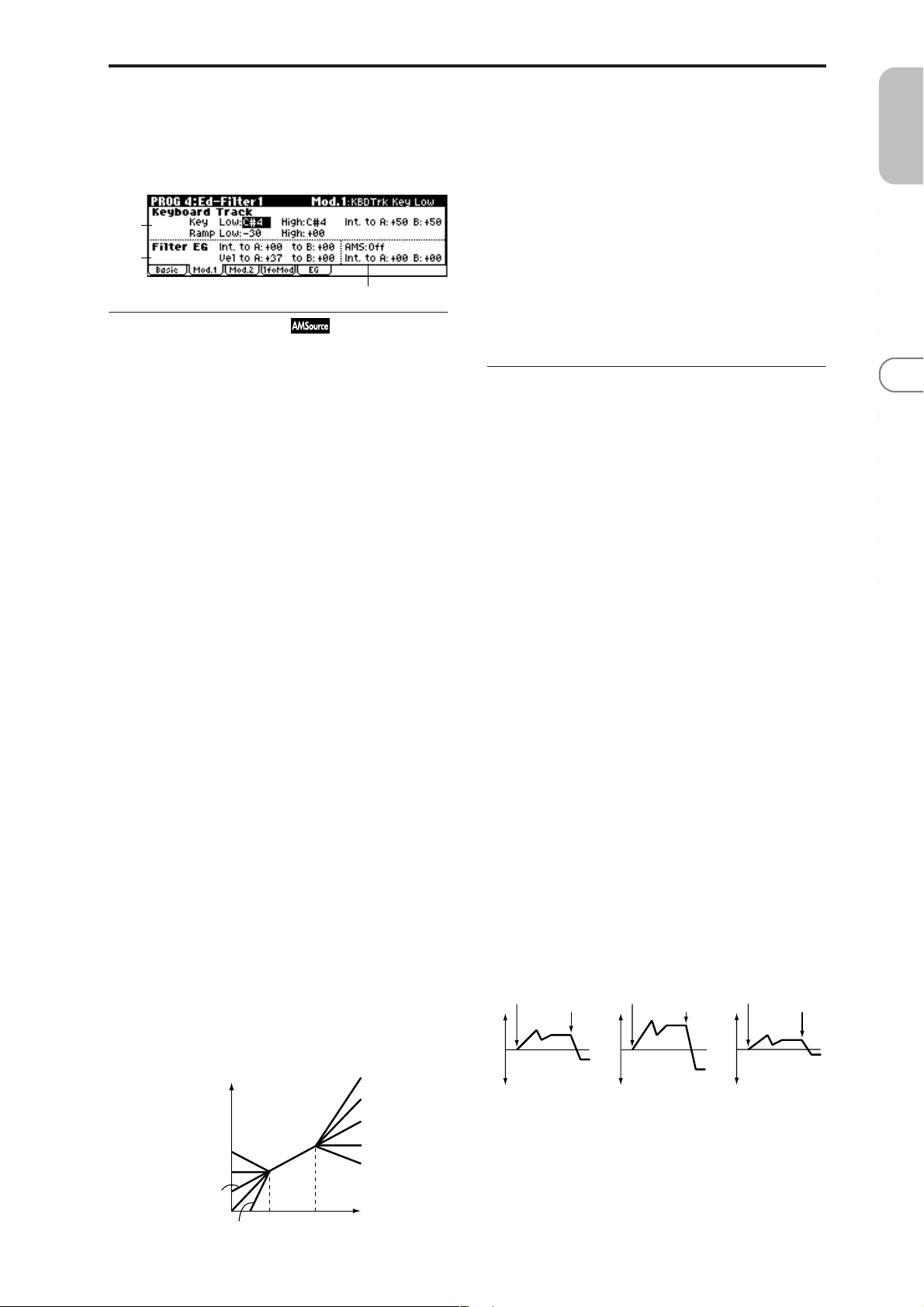
4–2: Mod.1 (Filter1 Modulation1)
Indicates settings for keyboard tracking which modifies the
tone by modulating the filter 1 cutoff frequency “Frequency
(A/B Frequency),” and intensity settings for the filter 1 EG, etc.
4–2a
4–2b
4–2c
4–2a: Keyboard Track
These settings specify keyboard tracking for the cutoff frequency of filter 1. The way in which the cutoff frequency is
affected by the position of the key (on the keyboard) that
you play can be specified by the Key: “Low” and “High,”
Ramp: “Low” and “High” parameters.
Key:
Specifies the note numbers at which keyboard tracking will
begin to be applied, and set the “Int. to A” and “(Int. to) B”
parameters to specify the depth and direction of the change
applied to filter 1 A and B.
For the range of notes between “Low (KBDTrk Key Low)”
and “High (KBDTrk Key High),” the cutoff frequency will
change according to the key location (pitch).
X50: You can also input a value by playing a note on the
keyboard while you hold down the [ENTER] button.
Low (KBDTrk Key Low) [C–1…G9]
Keyboard tracking will apply to the range below the specified note number.
Int. to A (KBDTrk Int. to A) [–99...+99]
Specifies the depth and direction of the effect on filter 1A
produced by keyboard tracking settings “Low (KBDTrk Key
Low),” “High (KBDTrk Key High),” “Low (KBDTrk Ramp
Low),” and “High (KBDTrk Ramp High).”
With positive (+) settings, the effect will be in the same
direction as the keyboard tracking settings.
With negative (–) settings, the effect will be in the opposite
direction.
Int. to B (KBDTrk Int. to B) [–99...+99]
Specifies the depth and direction of the effect on filter 1B
produced by keyboard tracking. (☞“Int. to A (KBDTrk Int.
to A)”)
4–2b: Filter EG
Int. to A (Intensity to A) [–99…+99]
Specifies the depth and direction of the effect that the timevarying changes created by the filter 1 EG will have on the
filter 1A cutoff frequency.
With positive (+) settings, the sound will become brighter
when the EG levels set by Filter 1 EG “L (Level parameters)”
and “T (Time parameters)” (4–5a) are in the “+” area, and
darker when they are in the “–” area.
With negative (–) settings, the sound will become darker
when the EG levels set by Filter 1 EG “L (Level parameters)”
and “T (Time parameters)” are in the “+” area, and brighter
when they are in the “–” area.
Int. to B (Intensity to B) [–99…+99]
Specifies the depth and direction of the effect that the timevarying changes created by the filter 1 EG will have on the
filter 1B cutoff frequency. (☞“Int. to A (Intensity to A)”)
PROG
0
123456789
High (KBDTrk Key High) [C–1…G9]
Keyboard tracking will apply to the range above the specified note number.
Ramp (Ramp Setting):
Specifies the angle of keyboard tracking.
Low (KBDTrk Ramp Low) [–99…+99]
High (KBDTrk Ramp High) [–99…+99]
If “Int. to A (KBDTrk Int. to A)” and “Int. to B (KBDTrk Int.
to B)” are set to +50, “Low (KBDTrk Ramp Low)” is set to
–62 and “High (KBDTrk Ramp High)” is set to +62, the angle
of the change in cutoff frequency will correspond to the key
location (pitch). This means that the oscillation that occurs
when you increase the “Resonance (A Resonance)” (4–1b)
will correspond to the keyboard location.
If you set “Low (KBDTrk Ramp Low)” to +43 and “High
(KBDTrk Ramp High)” to –43, the cutoff frequency will not
be affected by keyboard location. Use this setting when you
do not want the cutoff frequency to change for each note.
How cutoff frequency is affected by keyboard location
and the Ramp setting (“Int. to A,” “Int. to B”=+50)
Cutoff frequency
Low Ramp=+99
Low Ramp=+43
Low Ramp=0
Low Ramp=–62
Low Ramp=–99
Low Key
High Key
High Ramp=+99
High Ramp=+62
High Ramp=0
High Ramp=–43
High Ramp=–99
Key
Vel to A (Velocity to A) [–99…+99]
This parameter specifies the depth and direction of the effect
that velocity will have on the time-varying changes created
by the filter 1 EG (as set by “Filter 1 EG” 4–5) to control the
filter 1A cutoff frequency.
With positive (+) values, playing more strongly will cause
the filter 1 EG to produce greater changes in cutoff frequency . W ith negative (–) values, playing mor e strongly will
also cause the filter 1 EG to produce greater changes in cutoff frequency, but with the polarity of the EG inverted.
Vel to B (Velocity to B) [–99…+99]
This parameter specifies the depth and direction of the effect
that velocity will have on the time-varying changes created
by the filter 1 EG to control the filter 1B cutoff frequency.
(☞“Vel to A (Velocity to A)”)
Changes in cutoff frequency
Note-on
Softly played
(The setting of Intensity to A (4–2b))
Note-off
Note-on
Strongly played
Setting to +
Note-off
Note-on
Strongly played
Setting to –
Note-off
17
Page 25
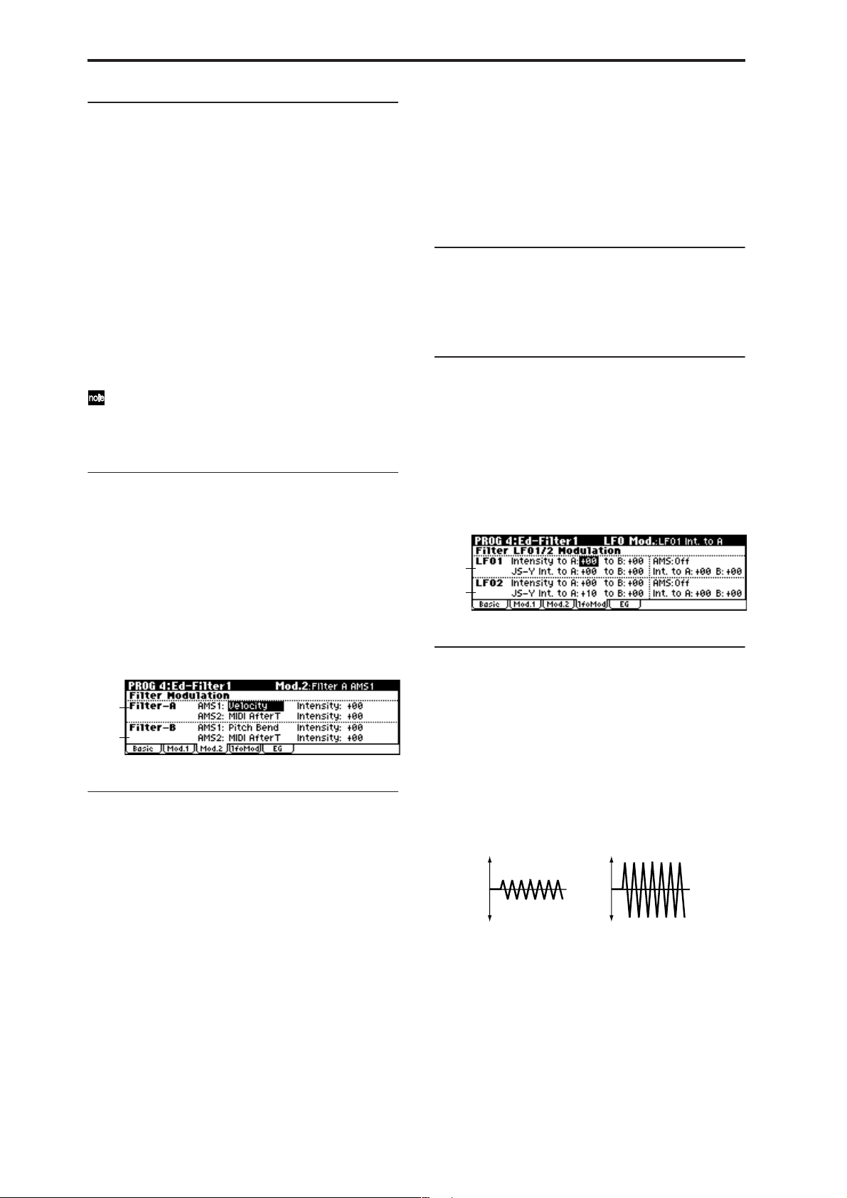
4–2c: AMS, Into to A, Int to B
This value is added to the setting of the Filter A “Frequency
(A Frequency)”(4–1b).
AMS (Filter EG AMS) [Off, (EXT)]
Indicates the source that will control the depth and direction
of the effect that the time-varying changes produced by the
filter 1 EG will have on the cutoff frequency of filters 1A and
1B (☞p.152 “AMS List”).
Int. to A (AMS Int. to A) [–99…+99]
Specifies the depth and direction of the effect that “AMS
(Filter EG AMS)” will have on filter 1A.
For details on how this will apply, refer to “Int. to A (Intensity to A).”
Int. to B (AMS Int. to B) [–99…+99]
Specifies the depth and direction of the effect that “AMS
(Filter EG AMS)” will have on filter 1B. (☞“Int. to A (Intensity to A).”)
The sum of the settings for “Int. to A (B),” “Vel to A
(B),” and “Int. to A (B) (AMS Int. to A/B)” will determine the depth and direction of the effect produced by
the filter EG.
■ 4–2: UTILITY
☞ “Write Program” (0–1), “Copy Oscillator,” “Swap Oscilla-
tor” (1–1)
AMS2 (Filter A AMS2) [Off, (PEG, AEG, EXT)]
Intensity (A AMS2 Intensity) [–99…+99]
Selects “AMS2 (Filter A AMS2),” and specify the depth and
direction of the effect that the selected source will have
(☞“AMS1,” “Intensity”).
4–3b: Filter-B Modulation
This will be displayed when “Type (Filter Type)” (4–1a) is
Low Pass & High Pass.
Two alternate modulation sources can be used to modulate
the cutoff frequency of filter 1B (☞“Filter-A Modulation”).
■ 4–3: UTILITY
☞ “Write Program” (0–1), “Copy Oscillator,” “Swap Oscilla-
tor” (1–1)
4–4: lfoMod (LFO Modulation)
Here you can use the filter 1 LFO to apply cyclic modulation
to the cutoff frequency of filter 1 (for oscillator 1) to create
cyclical changes in tone.
18
4–3: Mod.2 (Filter1 Modulation2)
Indicates settings for the controller that will modify the tone
by applying modulation to the filter 1 cutoff frequency “Frequency (A/B Frequency).”
If “Type (Filter Type)” (4–1a) is Low Pass Resonance, the filter B parameters will not be displayed.
4–3a
4–3b
4–3a: Filter-A Modulation
AMS1 (Filter A AMS1) [Off, (PEG, AEG, EXT)]
Indicates the source that will control modulation of the filter
1A cutoff frequency (☞p.152 “AMS List”).
Intensity (A AMS1 Intensity) [–99…+99]
Specifies the depth and direction of the effect that “AMS1
(Filter A AMS1)” will have.
X50: If “AMS1 (Filter A AMS1)” is set to PitchBend, setting
a positive (+) value for this parameter and moving the
[PITCH] wheel up will raise the cutoff frequency, while
moving the wheel down will lower the cutoff frequency.
With negative (–) values, the opposite will occur. This setting is summed with the value of the Filter A “Frequency (A
Frequency)” (4–1b) parameter.
microX: When “AMS1 (Filter A AMS1)” is JS X, a positive
(+) value for this parameter will cause the cutoff frequency
to rise when the joystick is moved toward the right, and fall
when the joystick is moved toward the left. With a negative
(–) value for this parameter, the opposite will occur.
4–4a
4–4b
4–4a: Filter LFO1 Modulation
Intensity to A (LFO1 Int. to A) [–99…+99]
Specifies the depth and direction of the modulation that
OSC1 LFO1 (set by “OSC1 LFO1” 3–1a) will have on the cutoff frequency of filter 1A.
Negative (–) settings will invert the phase.
Intensity to B (LFO1 Int. to B) [–99…+99]
Specifies the depth and direction of the modulation that
OSC1 LFO1 will have on the cutoff frequency of filter 1B
(☞“Intensity to A (LFO1 Int. to A)”).
Change in cutoff
Low setting High setting
JS–Y Int. to A (LFO1 JS–Y Int. to A)[–99…+99]
If 7–3a “Knob 1–B” is set to MIDI CC#02, you can
X50:
turn REALTIME CONTROL B-mode knob [1] to control
how OSC1 LFO1 will modulate the cutoff frequency of filter
1A. This parameter specifies the depth and direction of this
effect. As you increase this value, moving knob [1] toward
the right will allow OSC1 LFO1 to have a greater effect on
filter 1.
Page 26
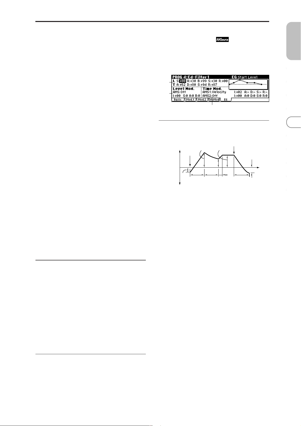
microX: By moving the joystick in the –Y direction
(down), you can control the depth at which OSC1 LFO1
modulates the cutoff frequency of filter 1A. This parameter
specifies the depth and direction of the control. For example,
as this value is raised, OSC1 LFO1 will have a correspondingly greater effect on filter 1 when the joystick is moved in
the –Y direction.
4–5: EG (Filter1 EG)
Here you can make settings for the EG that will produce
time-varying changes in the cutoff frequency of filters 1A
and 1B.
The depth of the effect that these settings will have on the
filter 1 cutoff frequency is determined by “Filter EG” (4–2b).
PROG
0
JS–Y Int. to B (LFO1 JS–Y Int. to B) [–99…+99]
If 7–3a “Knob1–B” is set to MIDI CC#02, you can turn
X50:
REALTIME CONTROL B-mode knob [1] to control how
OSC1 LFO1 will modulate the cutoff frequency of filter 1B.
This parameter specifies the depth and direction of this
effect. (☞“JS –Y Int. to A (LFO1 JS –Y Int. to A)”)
microX: By moving the joystick in the –Y direction
(down), you can control the depth at which OSC1 LFO1
modulates the cutoff frequency of filter 1B. This parameter
specifies the depth and direction of the control. (☞“JS –Y Int.
to A (LFO1 JS–Y Int. to A)”)
AMS (LFO1 AMS)
[Off, (PEG, FEG, AEG, KT, EXT)]
Selects a source that will control the depth and direction of
cutoff frequency change for both filters 1A and 1B (☞p.152
“AMS List”).
Int. to A (LFO1 AMS Int. to A) [–99…+99]
Specifies the depth and direction of the effect that “AMS
(LFO1 AMS)” will have on filter 1A. For example if you set
“AMS” to Pedal #04 and set Global 0–3a “Foot Pedal
Assign” to Foot Pedal (CC#04), higher settings of this
parameter will allow the OSC1 LFO1 to produce a greater
effect when you advance a foot pedal connected to the
ASSIGNABLE PEDAL jack.
4–5a
4–5b
4–5c
4–5a: Filter1 EG
Specifies the time-varying change produced by the filter 1
EG.
Note-off
Break
Point
Level
Decay
Time
Sustain Level
Slope
Time
Release
Time
Release
Level
Time
Attack Level
Note-on
The specified
cutoff
frequency
Start
Level
Attack
Time
L (Level parameters):
The result will depend on the filter that was selected in
“Type (Filter Type)” (4–1a). For example with the Low Pass
Resonance filter, positive (+) values of “Int. to A” (4–2b)
will cause the tone to be brightened by positive (+) levels,
and darkened by negative (–) levels.
123456789
Int. to B (LFO1 AMS Int. to B) [–99…+99]
Specifies the depth and direction of the effect that “AMS
(LFO1 AMS)” will have on filter 1B (☞“Int. to A (LFO1 AMS
Int. to A)”).
4–4b: Filter LFO2 Modulation
Adjusts the depth of the cyclic modulation applied by OSC1
LFO2 (set by “OSC1 LFO 2” 3–2) to the cutoff frequency of
filters 1A and 1B (☞“Filter LFO 1 Modulation” 4–4a).
Intensity to A (LFO2 Int. to A) [–99…+99]
Intensity to B (LFO2 Int. to B) [–99…+99]
JS–Y Int. to A (LFO2 JS–Y Int. to A)[–99…+99]
JS–Y Int. to B (LFO2 JS–Y Int. to B) [–99…+99]
AMS (LFO2 AMS)
[Off, (PEG, FEG, AEG, KT, EXT)]
Int. to A (LFO2 AMS Int. to A) [–99…+99]
Int. to B (LFO2 AMS Int. to B) [–99…+99]
■ 4–4: UTILITY
☞ “Write Program” (0–1), “Copy Oscillator,” “Swap Oscilla-
tor” (1–1)
S (Start Level) [–99…+99]
Specifies the change in cutoff frequency at the time of note-on.
A (Attack Level) [–99…+99]
Specifies the change in cutoff frequency after the attack time
has elapsed.
B (Break Point Level) [–99…+99]
Specifies the change in cutoff frequency after the decay time
has elapsed.
S (Sustain Level) [–99…+99]
Specifies the change in cutoff frequency that will be maintained from after the slope time has elapsed until note-off
occurs.
R (Release Level) [–99…+99]
Specifies the change in cutoff frequency that will occur when
the release time has elapsed.
T (Time parameters):
These parameters specify the time over which each change
will occur.
A (Attack Time) [00…99]
Specifies the time over which the level will change from
note-on until the attack level is reached.
D (Decay Time) [00…99]
Specifies the time over which the level will change from the
attack level to the break point level.
19
Page 27

S (Slope Time) [00…99]
Specifies the time over which the level will change after the
decay time has elapsed until the sustain level is reached.
R (Release Time) [00…99]
Specifies the time over which the level will change after
note-on occurs until the release level is reached.
4–5c: Time Mod. (Time Modulation)
These settings let you use alternate modulation to control
the “T (Time parameters)” of the filter 1 EG.
AMS1 (Time Mod. AMS1) [Off, (KT, EXT)]
Indicates the source that will control the “T (Time parameters)” of the filter 1 EG (☞p.152 “AMS List”).
4–5b: Level Mod. (Level Modulation)
These settings let you use alternate modulation to control
the “L (Level parameters)” of the filter 1 EG.
AMS (Level Mod. AMS) [Off, (KT, EXT)]
Indicates the source that will control the “L (Level parameters)” of the filter 1 EG (☞p.152 “AMS List”).
I (AMS Intensity) [–99…+99]
Specifies the depth and direction of the effect that “AMS
(Level Mod. AMS)” will have. With a setting of 0, the levels
specified by “Filter 1 EG” (4–5a) will be used, no additional
effect is produced.
For example, if “AMS (Level Mod. AMS)” is Velocity, and
you set “S (AMS SW Start),” “A (AMS SW Attack)” and “B
(AMS SW Break)” to + and set “I (AMS Intensity)” to a posi-
tive (+) value, the EG levels will rise as you play more
strongly. If “Intensity” is set to a negative (–) values, the EG
levels will fall as you play more strongly.
S (AMS SW Start) [–, 0, +]
Specifies the direction in which “AMS (Level Mod. AMS)”
will affect “S (Start Level).” When “I (AMS Intensity)” has a
positive (+) value, a setting of + for this parameter will
allow “AMS” to raise the EG level, and a setting of – will
allow “AMS” to lower the EG level. With a setting of 0 there
will be no change.
A (AMS SW Attack) [–, 0, +]
Specifies the direction in which “AMS (Level Mod. AMS)”
will affect “A(Attack Level).” When “I (AMS Intensity)” has
a positive (+) value, a setting of + for this parameter will
allow “AMS” to raise the EG level, and a setting of – will
allow “AMS” to lower the EG level. With a setting of 0 there
will be no change.
B (AMS SW Break) [–, 0, +]
Specifies the direction in which “AMS (Level Mod. AMS)”
will affect “B (Break Point Level).” When “I (AMS Intensity)” has a positive (+) value, a setting of + for this parameter will allow “AMS” to raise the EG level, and a setting of –
will allow “AMS” to lower the EG level. With a setting of 0
there will be no change.
Filter 1 EG changes (level) (AMS = Velocity, Intensity = a positive (+) value)
Note-on
Softly played note with “S,”
“A,” and “B” set to + (setting
of 4–5a: Filter 1 EG)
Note-off
Note-on
Strongly played note with
“S,” “A,” and “B” set to +
Note-off
Note-on
Strongly played note with
“S,” “A,” and “B” set to –
Note-off
I (AMS1 Intensity) [–99…+99]
Specifies the depth and direction of the effect that “AMS1
(Time Mod. AMS1)” will have. With a setting of 0, the times
specified by “Filter1 EG” (4–5a) will be used.
For example, if “AMS1 (Time Mod. AMS1)” is set to Flt KTr
+/+, the EG “T (Time parameters)” will be controlled by the
Keyboard Track (4–2a) settings. With positive (+) values of
this parameter, positive (+) values of “Ramp (Ramp Setting)” (4–2a) will lengthen the EG times, and negative (–)
values of “Ramp (Ramp Setting)” will shorten the EG times.
The direction of change is specified by “A (AMS1 SW
Attack),” “D (AMS1 SW Decay),” “S (AMS1 SW Slope),” and
“R (AMS1 SW Release).”
If “AMS1 (Time Mod. AMS1)” is set to Velocity, positive (+)
values of this parameter will cause EG times to lengthen as
you play more strongly, and negative (–) values will cause
EG times to shorten as you play more strongly.
With a setting of 0, the times specified by “Filter1 EG” will
be used.
A (AMS1 SW Attack) [–, 0, +]
Specifies the direction in which “AMS1 (Time Mod. AMS1)”
will affect the attack time. With positive (+) values of “I
(AMS1 Intensity),” setting this parameter to + will allow
AMS1 to lengthen the time, and setting this parameter to –
will allow AMS1 to shorten the time. With a setting of 0
there will be no change.
D (AMS1 SW Decay) [–, 0, +]
Specifies the direction in which “AMS1 (Time Mod. AMS1)”
will affect the decay time. With positive (+) values of “I
(AMS1 Intensity),” setting this parameter to + will allow
AMS1 to lengthen the time, and setting this parameter to –
will allow AMS1 to shorten the time. With a setting of 0
there will be no change.
S (AMS1 SW Slope) [–, 0, +]
Specifies the direction in which “AMS1 (Time Mod. AMS1)”
will affect the slope time. With positive (+) values of “I
(AMS1 Intensity),” setting this parameter to + will allow
AMS1 to lengthen the time, and setting this parameter to –
will allow AMS1 to shorten the time. With a setting of 0
there will be no change.
R (AMS1 SW Release) [–, 0, +]
Specifies the direction in which “AMS1 (Time Mod. AMS1)”
will affect the release time. With positive (+) values of “I
(AMS1 Intensity),” setting this parameter to + will allow
AMS1 to lengthen the time, and setting this parameter to –
will allow AMS1 to shorten the time. With a setting of 0
there will be no change.
Filter 1 EG changes (Time) (AMS = Velocity, Intensity = a positive (+) value)
Note-on
Note-off
Note-on
Note-off
Note-on
Note-off
20
Softly played note with “A,”
“D,” “S” and “R” set to +
(setting of 4–5a: Filter 1 EG)
Strongly played note with
“A,” “D,” “S” and “R” set to +
Strongly played note with
“A,” “D,” “S” and “R” set to –
Page 28
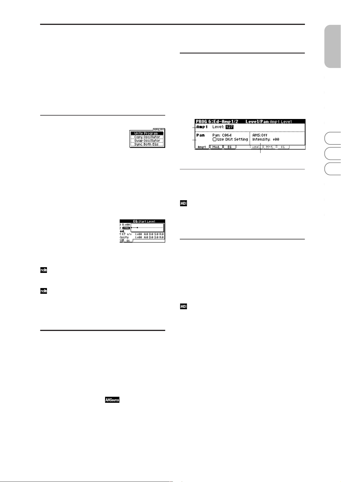
AMS2 (Time Mod. AMS2) [Off, (KT, EXT)]
I (AMS2 Intensity) [–99…+99]
A (AMS2 SW Attack) [–, 0, +]
D (AMS2 SW Decay) [–, 0, +]
S (AMS2 SW Slope) [–, 0, +]
R (AMS2 SW Release) [–, 0, +]
These parameters are the settings for “AMS2” to control the
“Time” parameters of the filter 1 EG (☞“AMS1 (Time Moc.
AMS1)”–“R (AMS1 SW Release)”).
■ 4–5: UTILITY
PROG 6: Ed–Amp1/2
Here you can make settings for amp 1 which controls the
volume of oscillator 1, and amp 2 which controls the volume
of oscillator 2. You can also specify the panning of each oscillator.
6–1: Lvl/Pan (Amp1 Level/Pan)
These parameters control the volume and pan of oscillator 1.
6–1a
6–1b
PROG
0
123456789
☞ “Write Program” (0–1), “Copy Oscillator,” “Swap Oscilla-
tor” (1–1)
For details on how to select the desired utility function, refer
to “PROG 0–1: UTILITY.”
Sync Both EGs
Choose “Sync Both EGs” from the utility menu, and press
the center of the ClickPoint; a check mark will appear at the
left of “Sync Both EGs,” and the “SYNC” icon will appear at
the left of the envelope curve in the display.
In this state, the filter 1 EG and the filter 2 EG can be edited
simultaneously. (Editing either one will cause the other to
change.)
“Sync Both EGs” cannot sync the filter EG and amp EG
independently. For example if you sync in 6–3d, it will
be synced here as well.
This can be selected only if “Mode (Oscillator Mode)”
(1–1a) is Double.
PROG 5: Ed–Filter2
5–1: Basic 5–2: Mod.1 (Filter2 Modulation1) 5–3: Mod.2 (Filter2 Modulation2) 5–4: lfoMod (LFO Modulation) 5–5: EG (Filter2 EG)
Indicates settings for filter 2, which controls the tone of oscillator 2. You can select either a 24 dB/oct low pass filter with
resonance, or a 12 dB/oct low pass filter and 12 dB/oct high
pass filter connected in series. Filter 2 can be used when
“Mode (Oscillator Mode)” (1–1a) is Double. (☞“PROG 4:
Ed–Filter 1”)
6–1c
6–1a: Amp1 Level
Level (Amp1 Level) [000…127]
Sets the volume of oscillator 1.
The volume of a program can be controlled by CC#7
(volume) and CC#11 (expression). The r esulting level is
determined by summing the values of CC#7 and
CC#11. The Global MIDI channel “MIDI Channel”
(GLOBAL 1–1a) is used for control.
6–1b: Pan
Pan (Amp1 Pan)
[Random, L001…C064…R127]
Sets the pan (stereo location) of oscillator 1.
A setting of L001 places the sound at far left, C064 in the
center, and R127 to far right.
Random: The sound will be heard from a different location
at each note-on.
This can be controlled by CC#10 (panpot). A CC#10
value of 0 or 1 will place the sound at the far left, a
value of 64 will place the sound at the location specified
by the “Pan” setting for each oscillator, and a value of
127 will place the sound at the far right. This is controlled on the global MIDI channel “MIDI Channel”
(GLOBAL 1–1a).
Use DKit Setting [Off, On]
This is valid when “Mode (Oscillator Mode)” (1–1a) is set to
Drums.
On (checked): The sound will be output at the “Pan” setting
that has been made for each key of the drum kit (GLOBAL
4–3a). When “Mode (Oscillator Mode)” is Drums, you will
normally use this setting.
Off (unchecked): All notes will be output as specified by the
“Pan (Amp1 Pan)” setting.
21
Page 29
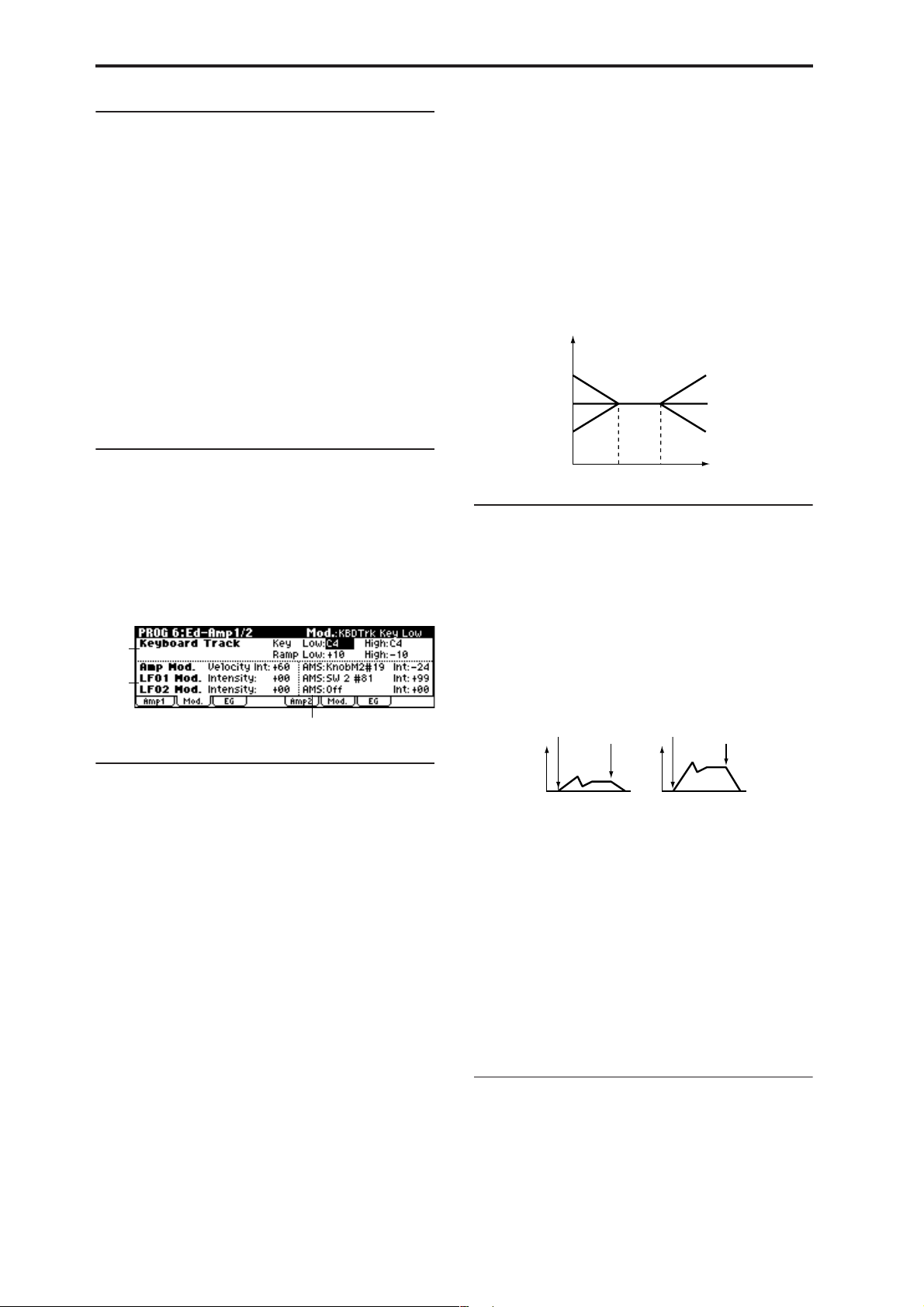
6–1c: AMS, Intensity
AMS (Pan AMS)
[Off, (PEG, FEG, AEG, LFO, KT, EXT)]
Indicates the source that will modify pan (☞p.152 “AMS
List”). This change will be relative to the “Pan (Amp1 Pan)”
setting.
Intensity [–99…+99]
Specifies the depth of the effect produced by “AMS (Pan
AMS).”
For example, if “Pan (Amp1 Pan)” is set to C064 and “AMS
(Pan AMS)” is Note Number, positive (+) values of this
parameter will cause the sound to move toward the right as
the note numbers increase beyond the C4 note (i.e., as you
play higher), and toward the left as the note numbers
decrease (i.e., as you play lower). Negative (–) values of this
parameter will have the opposite effect.
Low (KBDTrk Ramp Low) [–99…+99]
With positive (+) values of this parameter, the volume will
increase as you play notes below the “Low (KBDTrk Key
Low)” note number. With negative (–) values, the volume
will decrease.
High (KBDTrk Ramp High) [–99…+99]
With positive (+) values of this parameter, the volume will
increase as you play notes above the “High (KBDTrk Key
High)” note number. With negative (–) values, the volume
will decrease.
Volume change produced by key position and Ramp settings
Volume
Ramp Low=+99
Ramp Low=0
Ramp Low=–99
Ramp High=+99
Ramp High=0
Ramp High=–99
■ 6–1: UTILITY
☞ “Write Program” (0–1), “Copy Oscillator,” “Swap Oscilla-
tor” (1–1)
6–2: Mod. (Amp1 Modulation)
These settings allow you to apply modulation to amp 1 (for
oscillator 1) to modulate the volume.
6–2a
6–2b
6–2c
6–2a: Keyboard Track
These parameters let you use keyboard tracking to adjust
the volume of oscillator 1. Use the “Key” and “Ramp”
parameters to specify how the volume will be affected by
the position on the keyboard of the note that you play.
Key (Keyboard Track Key):
Specifies the note number at which keyboard tracking will
begin to apply.
The volume will not change between “Low (KBDTrk Key
Low)” and “High (KBDTrk Key High).”
X50: You can also input a value by playing a note on the
keyboard while you hold down the [ENTER] button.
Low (KBDTrk Key Low) [C–1…G9]
Keyboard tracking will apply to the range of notes below the
note number you specify here.
KBDTrk Low KBDTrk High
Key
6–2b: Amp Mod., LFO1 Mod., LFO2 Mod.
Indicates settings to specify how the volume of oscillator 1
will be controlled by velocity, OSC1 LFO1, and OSC1 LFO2.
Amp Mod. (Amp Modulation):
Velocity Int. (Amp Velocity Int.) [–99…+99]
With positive (+) values, the volume will increase as you
play more strongly.
With negative (–) values, the volume will decrease as you
play more strongly.
Volume change (with positive (+) values of this parameter)
Note-on
Note-off
Softly played
LFO1 Mod. (LFO1 Modulation):
Intensity (LFO1 Intensity) [–99…+99]
These parameters let you use “OSC1 LFO1” (3–1) to control
the oscillator 1 volume.
Negative (–) values will invert the LFO waveform.
LFO2 Mod. (LFO2 Modulation):
Intensity (LFO2 Intensity) [–99…+99]
Specifies the depth and direction of the effect that “OSC1
LFO2”(3–2) will have on the volume of oscillator 1.
Negative (–) values will invert the LFO waveform.
Note-on
Strongly played
Note-off
22
High (KBDTrk Key High) [C–1…G9]
Keyboard tracking will apply to the range of notes above the
note number you specify here.
Ramp (Ramp Setting):
Specifies the angle of the keyboard tracking.
6–2c: AMS, Int.
AMS (Amp AMS) [Off, (PEG, FEG, EXT)]
Indicates the source that will control the volume of amp 1
(☞p.152 “AMS List”) (EXT) Velocity cannot be selected.
Int. (AMS Intensity) [–99…+99]
Specifies the depth and direction of the effect that “AMS
(Amp AMS)” will have.
Page 30
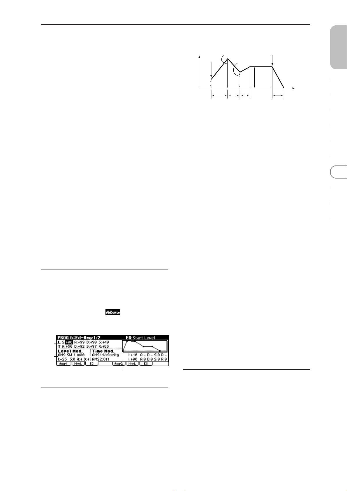
The actual volume will be determined by summing the
value of the changes produced by the amp EG with the values of Alternate Modulation etc., and if the levels of the amp
EG are low, the modulation applied by Alternate Modulation will also be less.
For example if you set “AMS” to Pedal #04 and set Global 0–
3a “Foot Pedal Assign” to Foot Pedal (CC#04), positive (+)
settings of this parameter will make the volume increase
when you advance a foot pedal connected to the ASSIGNABLE PEDAL jack. However if the volume is already at the
maximum because of the EG settings etc., it cannot be
increased any farther. With negative (–) settings of this
parameter, advancing the pedal will decrease the volume.
Amplifier EG
Attack Level
Volume
Note-on
Start
Level
Attack
Time
Break Point
Decay
Time
L (Level parameters):
Slope
Time
Sustain
Level
Note-off
Release Time
PROG
0
Time
123456789
AMS (LFO1 AMS)
[Off, (PEG, FEG, AEG, KT, EXT)]
Indicates the source that will control the depth by which
“OSC1 LFO1” (3–1) will modulate the volume of oscillator 1
(☞p.152 “AMS List”).
Int. (AMS Intensity) [–99…+99]
Specifies the depth and direction of the effect that “OSC1
LFO1” will have on the volume of oscillator 1. Negative (–)
values will invert the LFO waveform.
AMS (LFO2 AMS)
[Off, (PEG, FEG, AEG, KT, EXT)]
Indicates the source that will control the depth by which
“OSC1 LFO2” (3–2) will modulate the volume of oscillator 1
(☞p.152 “AMS List”).
Int. (AMS Intensity) [–99…+99]
Specifies the depth and direction of the effect that “OSC1
LFO2” will have on the volume of oscillator 1. Negative (–)
values will invert the LFO waveform.
■ 6–2: UTILITY
☞ “Write Program” (0–1), “Copy Oscillator,” “Swap Oscilla-
tor” (1–1)
S (Start Level) [00…99]
Specifies the volume level at note-on.
If you want the note to begin at a loud level, set this to a high
value.
A (Attack Level) [00…99]
Specifies the volume level that will be reached after the
attack time has elapsed.
B (Break Point Level) [00…99]
Specifies the volume level that will be reached after the
decay time has elapsed.
S (Sustain Level) [00…99]
Specifies the volume level that will be maintained from after
the slope time has elapsed until note-off occurs.
T (Time parameters):
A (Attack Time) [00…99]
Specifies the time over which the volume will change after
note-on until it reaches the attack level.
If the start level is 0, this will be the rise time of the sound.
D (Decay Time) [00…99]
Specifies the time over which the volume will change from
when it reaches the attack level until it reaches the break
point level.
6–3: EG (Amp1 EG)
Indicates settings to specify how Amp 1 will cause the volume of oscillator 1 to change over time.
6–3a
6–3b
6–3c
6–3a: Amp1 EG
These parameters specify how the amp 1 EG will change
over time.
S (Slope Time) [00…99]
Specifies the time over which the volume will change from
when it reaches the break point level until it reaches the sustain level.
R (Release Time) [00…99]
Specifies the time over which the volume will change after
note-off until it reaches 0.
6–3b: Level Mod. (Level Modulation)
These parameters let you use AMS to modulate the amp 1
EG levels that were specified in “Amp 1 EG” (6–3a).
AMS (Level Mod. AMS) [Off, (KT, EXT)]
Selects the source that will control the “Level” parameters of
the amp 1 EG (☞p.152 “AMS List”).
I (AMS Intensity) [–99…+99]
Specifies the depth and direction of the effect that “AMS
(Level Mod. AMS)” will have.
For example, if “AMS (Level Mod. AMS)” is Velocity, setting
“S (AMS SW Start),” “A (AMS SW Attack),” and “B (AMS
SW Break)” to + and setting “Intensity” to a positive (+)
23
Page 31

value will cause the amp 1 EG volume levels to increase as
you play more strongly. Setting “Intensity” to a negative (–)
values will cause the amp 1 EG volume levels to decrease as
you play more strongly. With a setting of 0, the levels will be
as specified in “Amp 1 EG” (6–3a).
S (AMS SW Start) [–, 0, +]
Specifies the direction in which “AMS (Level Mod. AMS)”
will change “S (Start Level).” If “I (AMS Intensity)” is set to
a positive (+) value, setting this parameter to + will allow
AMS to increase the EG level, and setting this parameter to –
will allow AMS to decrease the EG level. With a setting of 0,
no change will occur.
A (AMS SW Attack) [–, 0, +]
Specifies the direction in which “AMS (Level Mod. AMS)”
will change “A (Attack Level).” If “I (AMS Intensity)” is set
to a positive (+) value, setting this parameter to + will allow
AMS to increase the EG level, and setting this parameter to –
will allow AMS to decrease the EG level. With a setting of 0,
no change will occur.
B (AMS SW Break) [–, 0, +]
Specifies the direction in which “AMS (Level Mod. AMS)”
will change “B (Break Point Level).” If “I (AMS Intensity)” is
set to a positive (+) value, setting this parameter to + will
allow AMS to increase the EG level, and setting this parameter to – will allow AMS to decrease the EG level. With a setting of 0, no change will occur.
Amp 1 EG changes (Level) (AMS=Velocity, Intensity = a positive (+) value)
Note-on
Note-off
Softly played note when “S”=0
and “A” and “B” are set to +
(settings of 6–3a: Amp 1 EG)
Note-on
Note-off
Strongly played note
when “S”=0 and “A” and
“B” are set to +
Note-on
Note-off
Strongly played note
when “S”=0 and “A” and
“B” are set to –
A (AMS1 SW Attack) [–, 0, +]
Specifies the direction of the effect that “AMS1 (Time Mod.
AMS1)” will have on “A (Attack Time).” With positive (+)
values of “I (AMS1 Intensity),” setting this parameter to +
will allow AMS1 to lengthen the time, and setting it to – will
allow AMS1 to shorten the time. With a setting of 0 there
will be no effect.
D (AMS1 SW Decay) [–, 0, +]
Specifies the direction of the effect that “AMS1 (Time Mod.
AMS1)” will have on “D (Decay Time).” With positive (+)
values of “I (AMS1 Intensity),” setting this parameter to +
will allow AMS1 to lengthen the time, and setting it to – will
allow AMS1 to shorten the time. With a setting of 0 there
will be no effect.
S (AMS1 SW Slope) [–, 0, +]
Specifies the direction of the effect that “AMS1 (Time Mod.
AMS1)” will have on “S (Slope Time).” With positive (+)
values of “I (AMS1 Intensity),” setting this parameter to +
will allow AMS1 to lengthen the time, and setting it to – will
allow AMS1 to shorten the time. With a setting of 0 there
will be no effect.
R (AMS1 SW Release) [–, 0, +]
Specifies the direction of the effect that “AMS1 (Time Mod.
AMS1)” will have on “R (Release Time).” With positive (+)
values of “I (AMS1 Intensity),” setting this parameter to +
will allow AMS1 to lengthen the time, and setting it to – will
allow AMS1 to shorten the time. With a setting of 0 there
will be no effect.
Amp 1 EG changes (Time)
(AMS=Amp KTrk +/+, Intensity = a positive (+) value)
(When Amp Keyboard Track (6–2a) Low Ramp= a positive (+) value, and
High Ramp = a positive (+) value)
Note-on
Note-off
Note-on
Note-off
Note-on
Note-off
6–3c: Time Mod. (Time Modulation)
You can use two AMS sources to control the Amp 1 EG times
that were specified in “Amp 1 EG” (6–3a).
AMS1 (Time Mod. AMS1) [Off, (EXT, KT)]
Selects the source that will control the “T ime” parameters of
Amp 1 EG. (☞p.152 “AMS List”)
I (AMS1 Intensity) [–99…+99]
Specifies the depth and direction of the effect that “AMS1
(Time Mod. AMS1)” will have.
For example, if “AMS1 (Time Mod. AMS1)” is Amp KT +/+,
the (Amp) “Keyboard Track” settings (6–2a) will control the
EG “Time” parameters. With positive (+) values of this
parameter, positive (+) values of “Ramp (Ramp Setting)”
will cause EG times to be lengthened, and negative (–) val-
ues of “Ramp (Ramp Setting)” will cause EG times to be
shortened. The direction of the change is specified by “A
(AMS1 SW Attack),” “D (AMS1 SW Decay),” “S (AMS1 SW
Slope),” and “R (AMS1 SW Release).”
When “AMS1 (Time Mod. AMS1)” is Velocity, positive (+)
values will cause EG times to lengthen as you play more
strongly, and negative (–) values will cause EG times to
shorten as you play more strongly. With a setting of 0, the
EG times will be as specified in “Amp1 EG” (6–3a).
Settings of 6–3a: Amp 1EGLow-pitched note played
Amp 1 EG changes (Time) (AMS=Velocity, Intensity= a positive (+) value)
Note-on
Note-off
Softly played note with “A,”
“D,” “S” and “R” at + (settings
of 6–3a: Amp 1 EG)
with “A,” “D,” “S”, and “R”
at +
Note-on
Note-off
Strongly played note with
“A,” “D,” “S” and “R” at +
High-pitched note played
with “A,” “D,” “S”, and “R”
at –
Note-on
Note-off
Strongly played note with
“A,” “D,” “S” and “R” at –
AMS2 (Time Mod. AMS2) [Off, (EXT, KT)]
I (AMS2 Intensity) [–99…+99]
A (AMS2 SW Attack) [–, 0, +]
D (AMS2 SW Decay) [–, 0, +]
S (AMS2 SW Slope) [–, 0, +]
R (AMS2 SW Release) [–, 0, +]
These parameters specify how “AMS2 (Time Mod. AMS2)”
will control the amp 1 EG “Time” parameters (☞“AMS1
(Time Mod. AMS1)”–“R(AMS1 SW Release)”).
24
Page 32

■ 6–3: UTILITY
☞ “Write Program” (0–1), “Copy Oscillator,” “Swap Oscilla-
tor” (1–1)
For details on how to select the desired utility function, refer
to “PROG 0–1: UTILITY.”
Sync Both EGs
The amp 1 EG and the amp 2 EG can be edited simultaneously. (Editing either one will cause the other to change.)
Choose “Sync Both EGs” from the utility menu, and press
the center of the ClickPoint; a check mark will appear at the
left of “Sync Both EGs.” (☞4–5: UTILITY )
6–4: Lvl/Pan (Amp2 Level/Pan) 6–5: Mod. (Amp2 Modulation) 6–6: EG (Amp2 EG)
These will appear when “Mode (Oscillator Mode)” (1–1a) is
Double. (☞“PROG 6: Ed–Amp1/2”)
PROG 7: Ed–Arp/Ctrls
(Arpeggiator/Controls)
Here you can make settings for the arpeggiator used in the
program.
You can also assign the functions of the following controllers.
X50: The B-mode functions of REALTIME CONTROLS [1]–
[4] knobs, and the functions of [SW1] and [SW2].
microX: The B-mode functions of REALTIME CONTROLS
[1]–[4] knobs.
These arpeggiator settings can be linked when you switch
programs. To link, check the Program item in “Auto Arp.
“Program” (GLOBAL 0–1c): On.
The arpeggiator can be switched on/off by the [ARP ON/
OFF] button. When on, the LED will light.
The settings of the REALTIME CONTROLS C-mode [ARPGATE] knob, [ARP-VELOCITY] knob, [ARP-LENGTH]
knob, [TEMPO] knob, and [ARP ON/OFF] button can be
saved for each program.
These settings will be valid when Auto Arp. “Pr ogram”
is On.
You can control the arpeggiator from an external
sequencer, or record arpeggio note data on an external
sequencer. (☞p.178)
“Pattern,” “Resolution,” “Octave,” “Sort,” “Latch,”
“Key Sync.,” “Keyboard,” and “ (Tempo)” can also be
set in the Arp. Play page of 0: Play.
PROG
0
123456789
7–1: Setup (Arpeg. Setup)
7–1b
7–1a
7–1a: Arpeggiator Setup
☞ Refer to OG X50: p.91, microX: p.91.
Pattern* [Preset-0...Preset-4, U000...U250]
Selects the arpeggio pattern.
Preset-0: UP Preset Arpeggio Pattern
Preset-1: DOWN Preset Arpeggio Pattern
Preset-2: ALT1 Preset Arpeggio Pattern
Preset-3: ALT2 Preset Arpeggio Pattern
Preset-4: RANDOM Preset Arpeggio Pattern
U000...U250 for Preloaded User Arpeggio Pattern
Preset-0–Preset-4 are preset arpeggio patterns, U000–U250
are user arpeggio patterns. User arpeggio patterns can be
created in GLOBAL 5: Arp. Pattern.
X50: Arpeggio patterns U000–U250 can be selected using
the numeric buttons [0]–[9] and the [ENTER] button.
25
Page 33

Octave* [1, 2, 3, 4]
Specifies the number of octaves in which the arpeggio will
be played.
If a user arpeggio pattern is selected, the range of the
arpeggio will depend on the “Octave Motion” (GLOBAL 5–1c) setting.
Reso (Resolution)* [ , , , , , ]
Specifies the timing resolution of the arpeggio. The notes of
the arpeggio will be played at the interval you specify: ,
, , , , or . The speed of the arpeggio pattern is
determined by the “ (Tempo)” and the “Resolution.”
Gate [000...100(%), Step]
Specifies the length (gate time) of each note in the arpeggio.
000–100(%): Each note will be played with the specified gate
time.
Step: This is available when a user arpeggio pattern U000 –
U250 is selected for “Pattern.” When this is selected, the gate
time specified for each step will be used.
The gate time can also be controlled by the REALTIME
CONTROLS C-mode [ARP-GATE] knob. Rotating the knob
toward the left will shorten the gate time, and rotating it
toward the right will lengthen the gate time. When the knob
is at the 12 o’clock position, the gate time will be as specified
here.
Velocity [001...127, Key, Step]
Specifies the velocity of the notes in the arpeggio.
001–127: Each note will sound with the specified velocity
value.
Key: Each note will sound with the velocity value at which
it was actually played.
Step: This is available when a user arpeggio pattern U000–
U250 is selected for “Pattern.” When this is selected, the
velocity specified for each step will be used.
The velocity can also be controlled by the REALTIME CON-
TROLS C-mode [ARP-VELOCITY] knob. Rotating the knob
toward the left will decrease the velocity, and rotating it
toward the right will increase the velocity. When the knob is
at the 12 o’clock position, the velocity will be as specified
here.
Latch* [Off, On]
Specifies whether or not the arpeggio will continue playing
after you take your hand off the keyboard.
On (checked): The arpeggio will continue playing after you
remove your hand from the keyboard.
Off (unchecked): The arpeggio will stop when you remove
your hand from the keyboard.
Key Sync.* [Off, On]
Specifies whether the arpeggio pattern will begin when you
press a key, or whether it will always follow the “ (Tempo)”
setting.
On (checked): The arpeggio pattern will start playing from
the beginning when a note-on occurs from a condition
where no keys are pressed. This setting is suitable when you
are playing in realtime and want the arpeggio to play from
the beginning of the measure.
Off (unchecked): The arpeggio pattern will always play
according to the “ (Tempo) .”
Keyboard* [Off, On]
This specifies whether the notes you play on the keyboard
will be sounded as usual in addition to being sounded as
part of the arpeggio.
On (checked): The notes you play will be sounded on their
own, in addition to being sounded as part of the arpeggio.
For example if you simultaneously press two or more notes,
they will be sounded as usual in addition to being played as
arpeggiated notes.
Off (unchecked): Only the arpeggiated notes will be heard.
* These parameters can also be set in “0–3: Arp. Play”
7–1b: Arpeggiator Tempo
(Tempo) [040...240, EXT]
Sets the tempo.
☞p.3 “ (Tempo)” (0–1a)
■ 7–1: UTILITY
26
Swing [–100...+100(%)]
This parameter shifts the timing of the odd-numbered notes
of the arpeggio.
When Resolution =
Step
123456789
–50 –25 +25 +25
Swing
Sort* [Off, On]
This specifies the order in which the notes you press will be
arpeggiated.
On (checked): Notes will be arpeggiated in the order of their
pitch, regardless of the order in which you pressed them.
Off (unchecked): Notes will be arpeggiated in the order in
which you pressed them.
☞ “Write Program” (0–1)
Copy Arpeggiator
This command copies arpeggio settings.
1 Select “Copy Arpeggiator” to access the dialog box.
2 In “From” specify the copy source arpeggio settings
(mode, bank, number).
X50: You can press a PROG BANK button to select a bank.
You can also use numeric buttons [0]–[9] and the [ENTER]
button to select a number.
3 If you are copying from Combination or multi set, specify
whether you wish to copy from A or B.
4 To execute the Copy Arpeggio operation, press the
[MENU/OK] button. To cancel, press the [EXIT/CANCEL] button.
Page 34

7–2: Zone (Scan Zone)
7–2a
7–3a: Knob B Assign
Here you can assign functions (mainly various types of control change) to the B-mode of the REALTIME CONTROLS
knobs [1]–[4] (☞p.162 “Realtime Control Knobs B Assign
List”).
The functions you set here will take effect when you operate
the REALTIME CONTROLS knobs [1]–[4] in B-mode.
PROG
0
7–2a: Scan Zone
Zone Map
This shows the “Scan Zone” setting.
Key:
Btm (Bottom Key) [C–1...G9]
Top (Top Key) [C–1...G9]
These parameters specify the range of notes (keys) for which
the arpeggiator will function. “Top” is the upper limit, and
“Btm” is the lower limit.
Vel:
Btm (Bottom Velocity) [001...127]
Top (Top Velocity) [001...127]
Specifies the range of velocities for which the arpeggiator
will function. “Top” is the upper limit, and “Btm” is the
lower limit.
X50: The note number and velocity can also be specified by
holding down the [ENTER] button and pressing a note on
the keyboard.
■ 7–2: UTILITY
☞ “Write Program” (0–1), “Copy Arpeggiator” (7–1)
7–3: Controls
X50
Knob1–B (Knob1–B Assign)
[Off...MIDI CC#95]
Knob2–B (Knob2–B Assign)
[Off...MIDI CC#95]
Knob3–B (Knob3–B Assign)
[Off...MIDI CC#95]
Knob4–B (Knob4–B Assign)
[Off...MIDI CC#95]
X50: 7–3b: SW1/2 Assign
These settings assign functions to [SW1] and [SW2] (☞p.161
“SW1, SW2 Assign List”).
SW1 Assign [Off...Pitch Bend Lock]
Here you can assign a function to [SW1].
The on/off status of the switch is saved when the program is
written. When you change the function, it will be reset to the
“off” state.
SW1 Mode [Toggle, Momentary]
Specifies the on/off behavior of [SW1].
Toggle: The switch will alternate on/off each time you press
[SW1].
Momentary: The switch will be on only while you continue
holding [SW1].
SW2 Assign [Off...Pitch Bend Lock]
SW2 Mode [Toggle, Momentary]
Here you can assign a function to [SW2].
The functions that can be assigned to [SW2] are the same as
for [SW1], with the exception of SW2 Mod. (CC#81) instead
of SW1 Mod. (CC#80).
123456789
7–3a
microX
7–3a
■ 7–3: UTILITY
☞ “Write Program” (0–1)
7–3b
27
Page 35

PROG 8: Ed–InsertFX
☞ For details on insertion effect, refer to p.97 “6. Effect
Guide.”
CC#93 will control the Send 1 level for OSC 1 and 2,
and control change #91 will control the Send 2 level for
OSC 1 and 2. These are controlled on the global MIDI
channel “MIDI Channel” (GLOBAL 1–1a).
The actual send level is determined by summing these
values with the send level setting of each oscillator.
8–1: BUS
These settings specify the bus on which the output of the
oscillator will be sent, and adjust the send levels to the master effects.
The following diagram shows the LCD screen when “Mode
(Oscillator Mode)” (1–1a) is set to Single or Double.
8–1a
8–1a: BUS
BUS Select:
BUS Select (All OSCs) [L/R, IFX, 1, 2, 1/2, Off ]
Specifies the bus to which oscillators 1 and 2 will be sent.
If this is set to 1/2, the oscillator pan settings (6–1b, 6–4)
will be used to output the sound in stereo from (INDIVIDUAL OUTPUT) 1/2. When the oscillator pan is
controlled by CC#10 (pan) or AMS (Alternate Modulation Source), the sound will be output with the pan setting that is in effect at note-on. Unlike the case when
this is set to L/R to output the sound from (MAIN OUT PUT) L/MONO and R, the pan of a sounding note will
not change in real-time.
If you wish to adjust the pan in real-time while playing
a note and output the sound from (INDIVIDUAL OUTPUT) 1/2, set “BUS Select” to IFX, set “IFX” to 00: No
Effect, and set the “BUS Select” (8–2a) after passing
through IFX to 1/2.
MFX Send:
OSC1 Send1 [000...127]
Sets the volume (send level) at which the output of OSC1
will be sent to master effect 1. This is valid when “BUS
Select” is set to L/R or Off.
If “BUS Select” is set to IFX, the send levels to master effect 1
and 2 are set by “S1 (Send1(MFX1))” and “S2
(Send2(MFX2))” (8–2a) after passing through IFX of the
Setup page.
OSC1 Send2 [000...127]
Sets the volume (send level) at which the output of OSC1
will be sent to master effect 2 (☞“OSC1 Send1”).
OSC2 Send1 [000...127]
OSC2 Send2 [000...127]
Sets the volume (send level) at which the output of OSC2
will be sent to master effects 1 and 2. These parameters will
be valid when “Mode (Oscillator Mode)” (1–1a) is set to
Double and “BUS Select” is set to L/R or Off (☞“OSC1
Send1”).
8–1b: Use DKit Setting
The LCD screen shown below is for when “Mode (Oscillator
Mode)” (1–1a) is set to Drums.
8–1b
Use DKit Setting [Off, On]
This will be available when “Mode (Oscillator Mode)” is set
to Drums. If the “Mode (Oscillator Mode)” is Single or
Double, this setting has no effect.
On (checked): The “BUS (BUS Select)” (GLOBAL 4–3a) set-
ting for each key of the selected drum kit will be used.
Check this when you want to apply an insert effect to an
individual drum instrument, or to output an individual
drum instrument to one of the INDIVIDUAL OUTPUT
jacks.
Off (unchecked): The setting of the “BUS Select,” “MFX
Send” (8–1a) parameter described below will be used. All
drum instruments will be sent to the specified bus.
■ 8–1: UTILITY
☞ “Write Program” (0–1)
For details on how to select the desired utility function, refer
to “PROG 0–1: UTILITY.”
Copy Insert Effect
This command copies effect settings from Program, Combination, Multi set.
1 Select “Copy Insert Effect” to access the dialog box.
2 In “From” select the copy source mode, bank, and num-
ber.
X50: You can press a PROG BANK button to select a bank.
You can also use numeric buttons [0]–[9] and the [ENTER]
button to select a number.
3 Select the effect that you wish to copy. You can also copy
from a master effect.
If you are copying from a master effect, the result may
not be identical, due to differences in the routing and
level settings of a master effect.
28
Page 36

4 If you check “Post IFX Mixer Setting,” the “Pan (CC#8),”
“BUS Select,” “S1 (Send1(MFX1))” and “S2 (Send2(MFX2))”
settings that follow the copy source insert effect will also be
copied. If you do not check this, only the effect type and its
parameters will be copied.
5 To execute the Copy Insert Effect command, press the
[MENU/OK] button. To cancel, press the [EXIT/CANCEL] button.
8–2: Setup
Here you can select the type of insert effect, turn it on/off,
pan etc.
The direct sound (Dry) of an insert effect is always stereo
input and output. The input/output of the effect sound
(Wet) will depend on the effect type (☞p.98).
8–2a
8–2b
8–2a: InsertFX Setup
IFX On/Off [Off, On]
Selects the insert effect on/off.
When this is Off, the input will be output without change.
(For 00: No Effect, on/off will produce the same result.)
Separately from this setting, you can use control change
#92 to turn off insert effect. A value of 0 will be off, and
a value of 1–127 will be the original setting. This message is received on the global MIDI channel specified
by “MIDI Channel” (GLOBAL 1–1a).
Insert Effect [00...89: name]
Indicates the type of insert effect.
For “Insert Effect” you can select from 89 types of effect: 01:
St.Amp Sim – 89: Reverb-Gate.
You can use the utility “Select by Category” (8–2c) to select
these effects by category.
Control change CC#93 will control the Send 1 level, and
control change CC#91 will control the Send 2 level.
These messages are received on the global MIDI channel specified by “MIDI Channel” (GLOBAL 1–1a).
8–2b: Routing
This displays the status of the insert effect.
This displays the routing of the insert effect, the specified
effect name, and the on/off status.
You can select (All OSCs) and use the VALUE controller to
specify “BUS Select” (☞8–1a).
■ 8–2: UTILITY
☞ “Write Program” (0–1), “Copy Insert Effect” (8–1)
For details on how to select the desired utility function, refer
to “PROG 0–1: UTILITY.”
Select by Category
Selects insert effect by category.
For the procedure, refer to “Select by Category” (☞p.2).
This command is valid when the 8–2 parameters are
selected.
8–3: IFX (Insert Effect)
Here you can set the effect parameters for the IFX that was
selected in the Setup page (☞p.104–).
PROG
0
123456789
Pan(CC#8) (Post IFX Pan CC#8)
[L000...C064...R127]
Sets the pan after the sound has passed through the insert
effect. This setting is valid only when the “BUS Select” from
the IFX output is set to L/R (☞p.99).
CC#8 will control the pan amount.
BUS Select [L/R, 1, 2, 1/2, Off]
Specifies the bus to which the sound will be sent after passing through the insert effect. Normally you will set this to L/
R. If you wish to output to INDIVIDUAL OUTPUT, set this
to 1, 2 or 1/2. The Off setting is used when you wish to use
“S1 (Send1(MFX1))” and “S2 (Send2(MFX2))” and in addition connect to the master effects in series.
S1 (Send1(MFX1)) [000...127]
S2 (Send2(MFX2)) [000...127]
Sets the send levels to the master effects 1 and 2 for the
sound that has passed through the insert effect. These settings are valid when “BUS Select” (8–1a) has been set to L/R
or Off.
Effect dynamic modulation (Dmod) is controlled on the
global MIDI channel “MIDI Channel” (GLOBAL 1–1a).
(☞p.157 “Dynamic Modulation Source (Dmod)” )
■ 8–3: UTILITY
☞ “Write Program” (0–1)
29
Page 37

PROG 9: Ed–MasterFX
☞ For details on master effects, refer to p.97 “6. Effect
Guide.”
Direction (Chain Direction)
[MFX1→MFX2, MFX2→MFX1]
Specifies the direction of the connection when MFX1 and
MFX2 are chained.
MFX1→MFX2: Connect from MFX1 to MFX2.
MFX2→MFX1: Connect from MFX2 to MFX1.
9–1: Setup
Here you can select the master effect types, switch them on/
off, specify chain order, and set the master EQ.
9–1a
9–1b
9–1c
9–1a: Master Effect Setup
The master effects do not output the direct sound (Dry). The
return level (“Rtn 1, 2”) sends the effect sound (Wet) to the L
and R bus, and this is mixed with the direct sound (“BUS
Select” L/R: 8–1a, 8–2a).
The master effects are monaural input. The sound that is
panned to L and R after passing through the oscillator and
insert effect is mixed to a monaural signal as adjusted by the
“S1 (Send1(MFX1))” and “S2 (Send2(MFX2))” levels, and
input to the master effects.
The master effects are mono-in stereo-out. Even when
a stereo-input type effect is selected, the input will be
monaural.
MFX1 On/Off, MFX2 On/Off [Off, On]
Switches master effect 1, 2 on/off. When off, the output will
be muted.
Separately from this setting, you can use CC#94 to switch
master effect 1 on/off, CC#95 to switch master effect 2
on/off. A value of 0 will be off, and a value of 1–127 will
be the original setting. This is controlled on the global
MIDI channel “MIDI Channel” (GLOBAL 1–1a).
Master Effect 1, 2 [00...89: name]
Indicates the effect type for master effect 1, 2. You can select
from 89 types of effect: 01: St.Amp Sim–89: Reverb-Gate. If
00: No Effect is selected, the output from the master effect
will be muted.
Rtn 1, 2 (Return 1, 2) [000...127]
Adjusts the return levels from the master effects to the L/R
bus (main output L/MONO, R).
Signal (Chain Signal)[L/R Mix, L Only, R Only]
When chain is On, this parameter specifies how the stereo
output signal of the first master effect will be connected to
the input (mono) of the next master effect.
L/R Mix: The stereo output L/R of the first master effect will
be mixed before being input to the next master effect.
L Only, R Only: Only the left or right channel of the output
will be input to the next master effect.
Level (Chain Level) [000...127]
Sets the send level from the first master effect to the next
master effect when chain is turned on.
9–1c: Master EQ Gain [dB]
Sets the amount of cut and boost for the three-band EQ
located immediately before the (MAIN OUTPUT) L/MONO
and R jacks. This is linked with the various “Gain” parameters of Master EQ (9–4).
Low [–18.0...+18.0]
Mid [–18.0...+18.0]
High [–18.0...+18.0]
The cutoff frequency for “Low,” “Mid” and “High” and the
“Q” of “Mid” can be adjusted in the MEQ page. These settings are in “dB” units.
■ 9–1: UTILITY
☞ “Write Program” (0–1)
For details on how to select the desired utility function, refer
to “PROG 0–1: UTILITY.”
Copy Master Effect
This command lets you copy any desired effect settings from
Program, Combination, Muliti set.
1 Select “Copy Master Effect” to access the dialog box.
30
9–1b: Chain
MFX Chain [Off, On]
On (checked): Chain (series connection) will be turned on
for MFX1 and MFX2. (☞p.102)
Off (unchecked): MFX 1 and MFX2 are operating in parallel.
2 In “From,” select the copy source mode, bank, and num-
ber.
X50: You can press a PROG BANK button to select a bank.
You can also use numeric buttons [0]–[9] and the [ENTER]
button to select a number.
Page 38

3 Select the effect that you wish to copy. If you select MFX
1 or 2, “Rtn (Return)” (return level) will be copied at the
same time. If you select Master EQ, only the master EQ
settings will be copied. You can also copy from an insert
effect. If you check “All,” all settings of the master effects
and master EQ will be copied.
If you copy from an insert effect the result may not be
identical, due to differences in routing and level settings.
4 In “To,” select the copy destination master effect.
5 To execute the Copy Master Effect command, press the
[MENU/OK] button. To cancel, press the [EXIT/CANCEL] button.
Swap Master Effect
This command swaps (exchanges) the settings of MFX1 and
MFX2.
1 Select “Swap Master Effect” to access the dialog box.
9–2: MFX 1 (Master Effect1) 9–3: MFX 2 (Master Effect2)
Indicates effect parameter settings for the MFX1 and 2
effects that were selected in the Setup page (☞p.104–).
Effect dynamic modulation (Dmod) is controlled on the
global MIDI channel “MIDI Channel” (GLOBAL 1–1a).
(☞p.157 “Dynamic Modulation Source (Dmod)”)
■ 9–2(3): UTILITY
☞ “Write Program” (0–1)
PROG
0
123456789
2 To execute the Swap Master Effect command, press the
[MENU/OK] button. To cancel, press the [EXIT/CANCEL] button.
Select by Category
Selects master effects by category.
For the procedure, refer to “Select by Category” (☞p.2).
This command is valid when the 9–1a parameters are
on.
9–4: MEQ (Master EQ)
The master EQ is a three-band stereo EQ. It is used to adjust
the overall tonality of the sound immediately before the L/R
bus is output to the (MAIN OUTPUT) L/MONO and R
jacks (☞p.149). The MEQ High Gain and the MEQ Low Gain
can be controlled by assigning a modualtion source to the
“Low Gain Mod-Src.” and “High Gain Mod-src.” functions
on this page.
■ 9–4: UTILITY
☞ “Write Program” (0–1)
31
Page 39

32
Page 40

2. Combination mode
COMBI PAGE MENU
For details on how to select pages in Combination mode,
refer to p.1.
Play 0: Play Select and play combinations.
Tone Adjust
Track Parameter 2: Ed–Track Param
MIDI Filter 1
MIDI Filter 2
Key Zone 5: Ed–Key Zone
Velocity Zone 6: Ed–Vel Zone
Arp/Controls 7: Ed–Arp/Ctrls
Insert Effect 8: Ed–InsertFX
Master Effect 9: Ed–MasterFX
1: Ed–Tone Adjust
3: Ed–MIDI Filter1
4: Ed–MIDI Filter 2
Select a program for each timbre, and
make, pan and level settings.
Select an arpeggio pattern and make
settings.
microX: Select an external control set.
(☞p.33)
Select the program used by each timbre.
Specify the pan and volume of each program.
Use Tone Adjust to adjust parameters.
(☞p.38)
MIDI, OSC, Pitch, delay, and scale settings for each timbre. (☞p.40)
MIDI message transmission/reception filter settings for each timbre, such as Prog
Change, JS, Ribbon and After Touch.
(☞p.42)
MIDI message transmission/reception filter settings for each timbre, such as
REALTIME CONTROL Knob, SW, and
Other Ctrl Change (☞p.44)
Key zone settings for each timbre.
(☞p.45)
Velocity zone settings for each timbre.
(☞p.46)
Arpeggiator settings. (Same as the 0:
Play parameters; can be edited from
either page.)
Controller settings. (☞p.47)
Bus and master effect send level settings
for each timbre.
Insert effect routing, selection, and settings. (☞p.50)
Master effect selection and settings.
Master EQ settings. (☞p.52)
COMBI 0: Play
In this display page you can select and play Combinations.
A Combi allows you to use up to 8 programs at one time.
0–1: Combi (Combination)
X50
0–1a
0–1b
microX
0–1a
0–1b
0–1a: Bank, Combi Select, Category,
Cat.Hold, 10’s Hold, (Tempo)
Bank (Bank Select) [Bank A…C]
This is the Combination bank display.
On this instrument, there are a total of 384 combination programs in three rewritable banks (A, B, C), each containing
128 combinations.
Bank A
Preloaded combinationsBank B
Bank C
X50: Use the front panel COMBI BANK [A]–[C] buttons to
select the bank.
COMBI
0
123456789
microX: Use the front panel COMBINATION [A]–[C] but-
tons to select the bank. If you press one of the COMBINATION [A]–[C] buttons, you will automatically enter
Combination mode regardless of the mode in which you
were.
Combi Select (Combination Select)
[0...127: name]
Here you can select a combination. Choose this parameter,
and use one of the following methods to select a combination.
X50:
• Turn the [VALUE] dial.
• Use the [INC][DEC] buttons.
• Use the numeric buttons [0]–[9] to enter a program
number, and press the [ENTER] button to finalize the
number.
33
Page 41

• Press the center of the ClickPoint to highlight the field,
then use [π][†] to select a program, and press the
center to finalize your selection.
• 10’s HOLD (☞p.34)
• Use COMBI BANK [A]–[C] to select a bank (☞p.33)
• Use “Cat. HOLD” to select by category (☞p.34)
• Use “Select by Category” to select by category (☞p.34)
• Use the foot switch (☞p.80, 164)
• Receive a MIDI program change (☞p.171)
microX:
• Turn the [VALUE] dial.
• Press the center of the ClickPoint to highlight the field,
then use [π][†] to select a program, and press the
center to finalize your selection.
• Use “Select by Category” to select by category (☞p.34)
• Use the [CATEGORY] button and PROGRAM/
COMBINATION buttons to select by category (☞p.2)
• Use the foot switch (☞p.80, 164)
• Receive a MIDI program change (☞p.171)
ping your foot on a pedal switch connected to the ASSIGNABLE SWITCH jack.
microX: If you set the GLOBAL 0–3: Foot page “Foot SW
Assign” parameter to T ap Tempo, you can specify the tempo
by tapping your foot on a pedal switch connected to the
ASSIGNABLE SWITCH jack.
0–1b: Combination Information
X50: Displays information about the selected combination.
This shows the functions that are assigned to “SW1,”
“SW2,” and the REALTIME CONTROLS B-mode [ASSIGNABLE 1–4] knobs.
microX: Displays information about the selected combina-
tion. This shows the functions that are assigned to the
REALTIME CONTROLS B-mode [ASSIGNABLE 1–4]
knobs.
Category [00...15: name]
This is the combination category display.
All combinations are organized into sixteen categories. You
can select a category, and then select from combinations that
belong to that category.
To select a combination by category, use the procedure
described below. (☞PROG 0–1a)
To specify the category for a combination, use Utility
“Write Combination” (0–1). To modify a category name,
use “Category Name Comb. 00–07, 08–15” (GLOBAL 3–
3/4).
Select by Category
Use the utility “Select by Category” to select a combination
by category. (☞PROG 0–1a)
microX: Category & Bank
Use the [CATEGORY] button and PROGRAM/COMBINATION buttons to select by category (☞p.2)
X50: Cat.HOLD
Press the [./HOLD] button and the display will indicate
. The category will be held (fixed). (☞PROG 0–1a)
To cancel, press the [./HOLD] button twice to turn off the
display.
X50: 10’s HOLD
When you press the [./HOLD] button a second time, the display will indicate , and the first digit of the combination number will be fixed. (☞PROG 0–1a)
To cancel, press the [./HOLD] button to turn off the
display.
(Tempo) [040...240, EXT]
Sets the tempo of the arpeggiator. This can be adjusted by
the REALTIME CONTROLS C-mode [TEMPO] knob.
EXT is shown if “MIDI Clock” (GLOBAL 1–1a) is set to ExtMIDI or Ext-USB, or if it is set to Auto and the unit is oper-
ating as a slave. The arpeggiator will synchronize to MIDI
clock messages from an external MIDI device.
You can also set this parameter from 7: Ed–Arp/Ctrls,
Setup.
X50: You can tap the [ENTER] button several times to set
the tempo to the corresponding interval. Alternatively, if
you set the GLOBAL 0–3: Foot page “Foot SW Assign”
parameter to Tap Tempo, you can specify the tempo by tap-
■ 0–1: UTILITY
For details on how to select the desired utility function, refer
to “PROG 0–1: UTILITY.”
Write Combination
This command writes an edited combination into this
instrument’s internal memory.
Be sure to write any combination that you wish to keep. If
the power is turned off or a different combination selected
before you write an edited combination, your edits cannot
be recovered.
For the procedure, refer to “Write Program” (PROG 0–1).
If you use “Category” to specify a category for the combination that you are writing, you will be able to select it by category when selecting combinations in COMBI 0: Play.
Solo Selected Timbre
The Solo function will alternately be switched on/off each
time you select “Solo Selected Timbre.”
1 Choose “Solo Selected Timbre” from the utility menu,
and press the center of the ClickPoint to execute. When
you execute, a check mark will be shown at the left of the
“Solo Selected Timbre” in the menu, and the Solo function will be turned on.
2 In pages that show parameters for an individual timbre,
you can select a timbre to Solo (in 0: Play, Prog page “Program Select,” etc.) so that only that timbre will sound and
the other timbres will be muted. The “Selected Timbre
Information” (0–2d) in each page will indicate “Solo.”
To solo a different timbre, select a parameter of the timbre that you wish to solo.
3 To defeat the Solo function, choose “Solo Selected Tim-
bre” from the utility menu once again, and press the center of the ClickPoint.
If a timbre that is muted by the Solo function has been
set to a “Status” (2–1a) of EXT or EX2, MIDI note-on/
off messages will not be transmitted by that timbre.
34
Page 42

Select by Category
Selects a combination by category.
For the procedure, refer to “Select by Category” (☞p.2)
X50
microX
0–2: Prog (Timbre Program)
Indicates the program that will be used by each timbre.
0–2a
0–2b
0–2c
0–2d
0–2a: Bank, Combi Select, Cat.Hold, 10’s
Hold, (Tempo)
Bank [Bank A…C]
Combi Select (Combination Select)
[0…127: name]
X50: Cat. (Cat. HOLD)
X50: 10’s (10’s HOLD)
(Tempo) [040...240, EXT]
In the same way as in the Combi page, select a combination
and set the tempo of the arpeggiator. (☞0–1a)
0–2b: Timbre Number & Category
Timbre Number & Category 1...8
This displays the timbre number and an abbreviated category name.
0–2c: Program Select, Program Name
• Press the center of the ClickPoint to highlight the field in
the display, use [π][†] to make your choice, and press
the center to confirm.
• Use PROG BANK [A]–[GM] to select a bank (☞p.1)
• Receive a MIDI program change to select a program
(☞p.171)
microX:
• Turn the [VALUE] dial.
• Press the center of the ClickPoint to highlight the field in
the display, use [π][†] to make your choice, and press
the center to confirm.
• Use “Select by Category” to choose from the desired
category (☞p.34)
• Receive a MIDI program change to select a program
(☞p.171)
When you select a combination on this instrument, a
MIDI program change for the selected combination
number will be transmitted on the global MIDI channel
“MIDI Channel” (GLOBAL 1–1a). At the same time,
bank select, program change, and volume (CC#7) messages will be transmitted on the MIDI channel specified
for each timbre that is set to “Status” (2–1a) of EXT or
EX2. However, these messages will not be transmitted
for timbres that are set to the same MIDI channel as the
global MIDI channel. In this case, EX2 timbres will
show the “Program Select” Bank as “–”, and will transmit the bank number that was specified in “Bank (EX2)
MSB” and “Bank (EX2) LSB” (2–1a).
MIDI messages transmitted when you operate this
instrument are transmitted on the global MIDI channel.
At the same time, timbres whose “Status” is EXT or EX2
will transmit the same messages on their own MIDI
channel.
If bank select and program change messages are
received on a MIDI channel that matches the MIDI
channel of a timbre whose “Status” (2–1a) is INT, the
program of that timbre will change. However if the
MIDI channel of the incoming message matches the
global MIDI channel “MIDI Channel,” then the combination will change.
If you do not want the combination to change, you can
either change the global MIDI channel so that it does
not match the channel on which the program change
messages are being received, or you can uncheck
“Combi (Combi Change)” (GLOBAL 1–1b). Alternately,
you can uncheck “Bank (Bank Change)” (GLOBAL 1–
1b) so that only the program number will change and
the bank will remain the same.
If you wish to change a program without changing the
combination, you can also set “Program Change” (3–1a)
so that the program will change on certain timbres but
not on others.
This parameter can also be set from the 1: Ed–Tone Adjust,
Prog page.
COMBI
0
123456789
Program Select [A000...g128]
Indicates the program that will be used by each timbre.
Choose this parameter, and use one of the following methods to select a program.
X50:
• Turn the [VALUE] dial.
• Use the [INC][DEC] buttons.
• Use numeric buttons [0]–[9] to enter the program
number, and press the [ENTER] button to confirm.
Program Name
This displays part of the program name selected for the timbre. In the case of the GM drums bank, drums bank (d) will
be indicated.
35
Page 43

0–2d: Selected Timbre Information
This shows information on the timbre (1–8) that is currently
selected for editing.
Timbre No.: Bank No., Prog No.: and name
This shows the timbre number , and the program bank, number and name selected for that timbre.
Status (INT, O ff, EX T, EX2)
This shows the MIDI and internal tone generator status for
each track.
Ch (01...16, Gch)
This shows the MIDI channel number specified for the timbre.
■ 0–2: UTILITY
☞ “Write Combination,” “Solo Selected Timbre” (0–1)
Select by Category
(Combi/Category, Prog T1...T8/Category)
Combinations or the programs used by each timbre can be
selected by category.
If you have selected “Combi Select,” selecting Utility “Select
by Category” will access the Combi/Category dialog box,
allowing you to select a combination by category. (☞p.35)
If you have selected “Program Select,” selecting Utility
“Select by Category” will access the Prog T1...T8/Category
dialog box, allowing you to select a program for each timbre
by category.
For the procedure of selecting by category, refer to p.2.
0–3: Mix (Mixer)
Here you can set the pan and volume for each timbre 1–8.
0–3a
0–3a: Pan, Volume
OSC1
Left
Left
OSC1
Left
Left
Center
Center
Center
Center
OSC2
OSC1: Amp1 Pan=L001
OSC2: Amp2 Pan=R127
Right
Pan (CC#10)
C064
L032
L001
R096
R127
Right
OSC2
OSC1: Amp1 Pan=C064
OSC2: Amp2 Pan=C064
Right
Pan (CC#10)
C064
L032
L001
R096
R127
Right
OSC1: Amp1 Pan=L032
Left
Center
Left
Center
OSC2: Amp2 Pan=R096
Right
Pan (CC#10)
C064
L032
L001
R096
R127
Right
If a mono-type insertion effect is inserted, the setting you
make here will be ignored. In this case, the “Pan (CC#8)”
parameter in 8: Ed–InsertFX, Setup page will adjust the panning of the sound after the insertion effect (☞p.99 “3.
Mixer”).
RND: The oscillator pan will change randomly at each noteon.
If “Status” (2–1a) has been set to INT, MIDI control
change #10 (panpot) messages can be received to control the setting. CC#10 values of 0 or 1 will place the
sound at far left, 64 at center, and 127 at far right.
Pan can be controlled by messages received on the
“MIDI Channel” (2–1a).
This parameter can also be set from the 1: Ed–Tone Adjust,
Mixer page.
Volume [000...127]
Adjusts the volume of each timbre 1–8.
The volume of each timbre is determined by summing
this volume value with the MIDI volume (CC#7) and
expression (CC#11). If “Status” (2–1a) has been set to
INT, incoming MIDI CC#7 or CC#11 messages will control the volume of a timbre. (However these messages
will not affect the setting of this parameter.)
If “Status” is EXT or EX2, the value of this parameter
will be transmitted as MIDI CC#7 when the combination is changed. However this will not be transmitted
by a timbre that is set to the same MIDI channel as the
global MIDI channel. This message is transmitted on
the “MIDI Channel” (2–1a) specified for each timbre.
This parameter can also be set from the 1: Ed–Tone Adjust,
Mixer page.
36
Pan [RND, L001...C064...R127]
Sets the pan for each timbre 1–8.
L001...C064...R127: A setting of L001 is far left and R127 is
far right. A setting of C064 will reproduce the pan setting
that was made for the oscillator in Program mode.
■ 0–3: UTILITY
☞ “Write Combination,” “Solo Selected Timbre” (0–1),
“Select by Category” (0–1, PROG 0–1)
Page 44

Hold Balance
Adjusts the volume of the Combi while preserving the volume balance between timbres 1–8.
Select the “Volume” of any timbre, choose “Hold Balance”
from the utility menu, and press the center of the ClickPoint.
A check mark will appear at the left of “Hold Balance.” (The
upper right of the LCD will indicate [Hold Bal.].)
In this state, adjusting any “Volume” value will simultaneously change the volume of the other timbres as well,
while preserving the volume balance between timbres 1–8.
0–4: Arp. A (Arpeggio Play A) 0–5: Arp. B (Arpeggio Play B)
Here you can select the arpeggiator settings for the combination. A combination can run two arpeggiators simultaneously.
Arpeggiator parameters can be edited in 7: Ed–Arp/Ctrls,
but certain major parameters can be edited in these pages as
well. You can edit these parameters in realtime, for example
by changing the arpeggio pattern while playing in COMBI 0:
Play.
To save the edits you make, use “Write Combination.” The
arpeggiator can also be edited in realtime by the REAL TIME
CONTROLS C-mode [TEMPO] knob, [ARP-GATE] knob,
[ARP-LENGTH] knob, and [ARP-VELOCITY] knob. (☞OG
p.91)
These parameters can also be set in COMBI 7: Ed–Arp/
Ctrls, Arp.A, Arp.B page.
■ 0–4(5): UTILITY
☞ “Write Combination,” “Solo Selected Timbre,” “Select by
Category” (0–1)
microX: 0–6: Ext. Control
External control lets you use the REALTIME CONTROLS
knobs to control an external MIDI device. You can assign a
MIDI control change and MIDI channel to each of the four
knobs, and switch between three such settings (A, B, C) to
control your external device. One set lets you transmit a
total of twelve (4 × 3) different MIDI control changes. These
are called “external control sets,” and you can choose from
64 such sets. (☞p.5)
This page only displays the settings that are assigned to
knob sets A, B, and C. Use Global mode to make external control assignments.
0–6a
COMBI
0
123456789
0–4a
0–4b
0–4(5)a: Arpeggiator Run, Timbre assign
Arpeggiator Run A, B (Run A, B) [Off, On]
When the [ARP ON/OFF] button is on, any arpeggiator that
is checked here will run if it is assigned to a timbre in
“Assign” (7–1b).
Even if the arpeggiator is on, you can turn A and B on/off
independently.
This parameter can also be set from the 7: Ed–Arp/Ctrls
Setup page.
Timbre assign
This displays the timbres 1–8 to which arpeggiators A and B
are assigned. This can be set in “Assign” (7–1b).
0–4(5)b: Arpeggiator A(B)
Pattern [Preset-0...Preset-4, U000...U250]
Reso (Resolution) [ , , , , , ]
Octave [1, 2, 3, 4]
Sort [Off, On]
Latch [Off, On]
Key Sync. [Off, On]
Keyboard [Off, On]
Sets the various parameters of the combination arpeggiator
(☞“PROG: Ed–Arp/Ctrls”).
0–6a: External Control
Ext. Control (Setup Select) [00...63]
Selects an external control set.
This setting is not written (saved) in the combination.
Select [A, B, C]
Shows the settings assigned to each knob of the external
control set. The currently-enabled set is highlighted. Use the
[SELECT] button to switch between groups (A, B, C).
MIDI Channel [01...16, Gch]
Indicates the MIDI channel
Gch: The message will be transmitted on the global MIDI
channel you specify in Global mode. The channel of all
knobs that are set to Gch can be changed simply by changing the global MIDI channel setting, instead of having to
change the channel of each knob individually.
CC# Assign [Off, 000...119]
Indicates the MIDI control change number transmitted by
the knob.
■ 0–6: UTILITY
☞ “Write Combination,” “Solo Selected Timbre,” “Select by
Category” (0–1)
37
Page 45

COMBI 1:
Ed–Tone Adjust
1–1: Prog (Timbre Program)
Indicates the bank and program for each timbre 1–8. These
parameters can also be set from the 0: Play, Prog page.
1–1a
1–1b
1–1c
1–1d
1–1a: Program Select, Program Name
Program Select
Indicates the program that will be used by each timbre.
(☞0–2c)
1–3: T A1 (Tone Adjust 1) 1–4: T A2 (Tone Adjust 2) 1–5: T A3 (Tone Adjust 3)
You can also use the Tone Adjust function to temporarily
adjust the tone of the program for each timbre.
While creating a combination, you might use this function to
soften the sound of a program or give it a faster attack so
that it fits better within the combination, without having to
return to Program mode and edit the program itself. For
each timbre, you can assign and adjust up to six parameters
such as the filter cutoff, resonance, filter EQ, and amp EG.
1–3a
1–3(4)(5)a: Destination 1–6, Value 1–6
Program Name
This displays part of the program name selected for each
timbre. (☞0–2c)
■ 1–1: UTILITY
☞ “Write Combination,” “Solo Selected Timbre” (0–1),
“Select by Category (Combi/Category, Prog T1...T8/Category)” (0–2)
1–2: Mix (Mixer)
Specifies the pan and volume for each timbre 1–8. These
parameters can also be set from the 0: Play, Mixer page.
1–2a
1–2a: Pan, Volume
Pan
Sets the pan of each timbre 1–8. (☞0–3a)
Volume
Sets the volume of each timbre 1–8. (☞0–3a)
Destination 1–6 [LPF Fc…Reverse]
Selects the parameter that you want to adjust.
Value 1–6 [–99…+99, –12.00…+12.00,
–1200…+1200, Off…On]
Specifies the value for the parameter you selected in “Destination 1–6.” If you set this to +00 or PRG, the setting of the
program will be used.
Normally , you should not select the same parameter for
more than one “Destination” in the same track. However if you do so, the parameters will operate as follows.
If you select other than Hold or Reverse
The “Value” of each “Destination” set to the same
parameter will be summed for each track. However, the
“Value” of the parameter being controlled by the “Destination” will not exceed the allowable range of settings. For example if you have assigned three Detune1
settings for the same track, and their “Value” settings
are set to +1000, +1000, and +1000 respectively, then the
result will be +1200. (The sum is +3000, but the value is
limited at the maximum of +1200 for the Detune1
parameter.) Settings of +1000, +1000, and –1000 would
produce a result of +1000.
Hold, Reverse
The last of the multiple “Destination” settings will be
valid.
“Destination 1–6” and “Value 1–6”
The parameters that can be controlled and their range of values are as follows.
38
■ 1–2: UTILITY
☞ “Write Combination,” “Solo Selected Timbre” (0–1)
LPF Fc (Low Pass Filter Cutoff Frequency)
[–99…+00…+99]
Adjusts the low pass filter cutoff frequency of program OSC
1/2. This will affect the brightness of the sound. The parameter will be controlled in the same way as when CC#74 is
received. (☞p.175)
Page 46

Reso.HP (Resonance/High Pass Filter Cutoff
Frequency) [–99…+00…+99]
Adjusts the resonance level of the low pass filter or the cutoff frequency of the high pass filter for program OSC 1/2.
The parameter that is controlled will depend on the filter
type specified for the program. The parameter will be controlled in the same way as when CC#71 is received. (☞p.175)
F EG Int (Filter EG Intensity) [–99…+00…+99]
Adjusts the filter EG intensity (the depth of the filter EG) for
program OSC1/2. The parameter will be controlled in the
same way as when CC#79 is received. (☞p.175)
A Vel I. (Amp Velocity Intensity) [–99…+00…+99]
Adjusts the amp velocity intensity (the degree to which
velocity will affect the amp) for program OSC 1/2. This controls the Amp Modulation “Velocity Intensity” parameter
(☞p.22 6–2b).
F.A EG A (Filter/Amp EG Attack Time)
[–99…+00…+99]
Adjusts the EG attack times of the program OSC 1/2 filter
and amp. To maximize the result of this adjustment, the
Amp EG sustain level, attack level, start level modulation,
and attack time modulation will also be adjusted at the same
time. The parameter will be controlled in the same way as
when CC#73 is received. (☞p.175)
F.A EG D (Filter/Amp EG Decay Time)
[–99…+00…+99]
Adjusts the EG decay time and slope time of the program
OSC 1/2 filter and amp. The parameter will be controlled in
the same way as when CC#75 is received. (☞p.175)
F.A EG S (Filter/Amp EG Sustain Level)
[–99…+00…+99]
Adjusts the EG sustain level of the program OSC 1/2 filter
and amp. The parameter will be controlled in the same way
as when CC#70 is received. (☞p.175)
F.A EG R (Filter/Amp EG Release Time)
[–99…+00…+99]
Adjusts the EG release time of the program OSC 1/2 filter
and amp. The parameter will be controlled in the same way
as when CC#72 is received. (☞p.175)
F EG A (Filter EG Attack Time) [–99…+00…+99]
F EG D (Filter EG Decay Time) [–99…+00…+99]
F EG S (Filter EG Sustain Level) [–99…+00…+99]
F EG R (Filter EG Release Time) [–99…+00…+99]
These adjust only the filter parameter as in “A (Attack
Time),” “D (Decay Time),” “S (Sustain Level),“ or “R
(Release Time)” respectively. (☞PROG 4–5a)
A EG A (Amp EG Attack Time) [–99…+00…+99]
A EG D (Amp EG Decay Time) [–99…+00…+99]
A EG S (Amp EG Sustain Level) [–99…+00…+99]
A EG R (Amp EG Release Time) [–99…+00…+99]
These adjust only the amp parameter as in “A (Attack
Time),” “D (Decay Time),” “S (Sustain Level),“ or “R
(Release Time)” respectively. (☞PROG 6–3a, 6–6a)
LFO1 Sp (LFO1 Speed) [–199…+00…+199]
Adjusts the LFO1 speed of program OSC 1/2. The parameter will be controlled in the same way as when CC#76 is
received. (☞p.175)
PLFO1 I. (Pitch LFO1 Intensity)
[–12.00…+00.00…+12.00]
Adjusts the program OSC 1/2 pitch LFO1 intensity (the
depth of pitch modulation produced by LFO1). The parameter will be controlled in the same way as when CC#77 is
received. (☞p.175)
LFO1 Fd (LFO1 Fade) [–99…+00…+99]
Adjusts the program OSC 1/2 LFO1 “Fade” parameter (the
time from when the LFO begins to take effect until it reaches
the maximum level; 3–1a ☞p.14).
LFO1 Dl (LFO1 Delay) [–99…+00…+99]
Adjusts the program OSC 1/2 pitch LFO1 delay (the time
from note-on until the LFO begins to take effect). The
parameter will be controlled in the same way as when
CC#78 is received. (☞p.175)
P.Strch (Pitch Stretch) [–12…+00…+12]
Simultaneously adjusts the program OSC 1/2 Transpose
and Tune parameters. This lets you create a rich variety of
tonal changes without impairing the character of the original sound.
This controls the same parameters as Performance Editor “Stretch (Pitch Stretch)” (0–2b). (☞p.4)
Dtune 1(Detune 1) [–1200…+0000…+1200]
Adjusts the tuning of program OSC 1. This controls the
OSC1 Multisample “Tune” parameter (1–2c ☞p.8).
Dtune 2 (Detune 2) [–1200…+0000…+1200]
Adjusts the tuning of program OSC 2. This controls the
OSC2 Multisample “Tune” parameter (1–2c ☞p.8).
This is valid only if the program’s “Oscillator Mode”
(1–1a ☞p.6) is set to Double.
Hold [Off, PRG, On]
Controls the program’s Voice Assign - “Hold” parameter (1–
1b ☞p.6).
If you turn this Off, the OSC1/2 Amp EG Release Time
parameter will be set to 0 in order to make full use of the
effect.
Normally you can make effective use of this with a drum
program. When you turn this Off, the key-off timing will be
valid, letting you use the key-on/off timing to control the
gate time. Sometimes you can obtain an interesting effect by
turning this Off for a previously-created drum track.
Reverse [Off, PRG, On]
Controls the “Rev (Reverse)” parameter (1–2b ☞p.8, GLO-
BAL 4–1b ☞p.87) for each Multisample or Drumsample of
program OSC1/2.
If you turn this On, all multisamples and drum samples will
play backward. If you turn this Off, all multisamples and
drum samples will play normally. If you set this to PRG, the
settings of the program (or the drum kit used by the program) will be used. Normally you can make effective use of
this with a drum program.
■ 1–3(4)(5): UTILITY
☞ “Write Combination,” “Solo Selected Timbre” (0–1)
COMBI
0
123456789
39
Page 47

COMBI 2: Ed–Timbre Param
■ 2–1: UTILITY
☞ “Write Combination,” “Solo Selected Timbre” (0–1)
2–1: MIDI
Here you can make MIDI settings for each timbre.
2–1a
2–1a: Status, MIDI Channel, Bank(EX2)
MSB/LSB
Status [INT, O ff, EX T, EX2]
Specifies the status of MIDI and the internal tone generator
for each timbre.
INT: When you play this instrument, the internal tone generator will sound, and will also sound in respond to MIDI
messages received from an external MIDI device. MIDI data
will not be transmitted.
Off: The program will not sound. Nor will MIDI data be
transmitted.
EXT: Playing this instrument will not cause it to sound, but
it will transmit data via MIDI to control external MIDI
devices.
EX2: “Bank (EX2) MSB” and “Bank (EX2) LSB” (2–1a) will be
enabled. Instead of the bank numbers for A–G(d) that can be
selected on this instrument, the bank numbers you specify
here will be transmitted via MIDI. In other respects this is
the same as EXT.
INT
EXT, EX2
MIDI Channel [01...16, Gch]
Set the MIDI transmit/receive channel for each timbre 1–8.
Gch: The timbre will use the channel that has been selected
as the global MIDI channel “MIDI Channel” (GLOBAL 1–
1a).
When “Status” is INT, MIDI messages will be received on
the channel you specify here. If this setting is the same as the
global MIDI channel, the internal tone generator will sound
according to the internal settings. If this is set to EXT or EX2,
playing this instrument will transmit MIDI messages on the
MIDI channel specified here. (Messages will also be transmitted simultaneously on the global MIDI channel.)
Bank(EX2) MSB [000:000...127:127]
Bank(EX2) LSB [000:000...127:127]
Specifies the bank number that will be transmitted when
“Status” is set to EX2. If “Status” is not set to EX2, this setting has no effect.
MIDI IN
Tone
generator
MIDI OUT
2–2: OSC
These settings specify how each timbre will be sounded.
2–2a
2–2a: Force OSC Mode, OSC Select, Porta-
mento
Force OSC Mode [PRG, Poly, Mono, LGT ]
Specifies the “Mode (Voice Assign Mode)” (PROG 1–1b) of
the program selected for each timbre 1–8.
PRG: The settings of the program will be used.
Poly: The timbre will play polyphonically, regardless of the
settings of the program.
Mono: The timbre will play monophonically, regardless of
the settings of the program.
LGT (Legato): The timbre will play monophonically, with
single triggering (legato).
With settings of Mono or LGT, the note priority will be
according to the “Priority” (PROG 1–1b) setting of the program.
OSC Select [Both, OSC1, OSC2]
Specifies the “Mode (Oscillator Mode)” (PROG 1–1a) of the
program selected for each timbre 1–8. If the “Mode (Oscillator Mode)” is Double, you can specify that either or both
oscillators sound.
Both: OSC1 and 2 will sound as specified by the settings of
the program.
OSC1: Only OSC1 will sound.
OSC2: Only OSC2 will sound. If “Mode (Oscillator Mode)”
is Single or Drums, there will be no sound.
Portamento [PRG, Off, 001...127]
Indicates portamento settings for each timbre 1–8.
PRG: Portamento will be applied as specified by the program settings.
Off: Portamento will be off, even if the original program settings specified for it to be on.
001...127: Portamento will be applied with the portamento
time you specify here, even if it is turned off by the program
settings.
If the “Status” (2–1a) is set to INT, CC#05 (portamento
time) and CC#65 (portamento switch) messages will be
received to control and change this setting. (If the setting is PRG, CC#05 portamento time will not be
received.) These messages will be received on the MIDI
channel specified for each timbre by “MIDI Channel”
(2–1a).
■ 2–2: UTILITY
☞ “Write Combination,” “Solo Selected Timbre” (0–1)
40
Page 48

2–3: Pitch
Here you can make pitch-related settings for each timbre.
■ 2–3: UTILITY
2–3a
2–3a: Transpose, Detune, Bend Range
Transpose [–24…+24]
Adjusts the pitch of each timbre in semitone steps.
12 units equal one octave.
When “Status” (2–1a) is INT, this parameter will affect
the pitches sounded by the X50/microX. When “Status”
is EXT, this parameter will affect the note numbers of
the MIDI note messages that are transmitted.
For example if you make settings of +04 and +07
respectively for two timbres that are set to EXT, playing
the C key will transmit a C note number on the global
MIDI channel, and at the same time will also transmit E
and G note numbers on the MIDI channels of those timbres.
Detune (BPM Adj.) [–1200...+1200]
Adjusts the pitch of each timbre in one-cent units.
0: Normal pitch.
You can also use the Utility “Detune BPM Adj.” (2–3b)
page menu command to automatically make a detune
setting from a calculation in BPM units.
“Transpose” and “Detune” can be controlled via MIDI
RPN messages. Depending on the “Mode (Oscillator
Mode)” (PROG 1–1a) settings of the programs used by
timbres 1–8, they can be controlled as follows.
When “Mode (Oscillator Mode)” is Single or Double
MIDI RPN Coarse Tune can be received to control and
change the setting of “Transpose,” and RPN Fine Tune
can be received to control and change the setting of
“Detune.”
When “Mode (Oscillator Mode)” is Drums, MIDI RPN
Coarse Tune and Fine Tune can be received to control
and change the setting of “Detune.” The controllable
range is ±1 octave for coarse tune and fine tune
together.
☞ “Write Combination,” “Solo Selected Timbre” (0–1)
Detune BPM Adjust
If the program of a timbre uses a phrase or rhythm loop
multisample is matched to a specific BPM, you can use this
Utility to modify its BPM value. “Detune BPM Adjust”
changes the BPM of a phrase or rhythm by modifying its
pitch.
This is valid for a track when timbre “Detune” is selected.
When this Utility is executed, the selected “Detune” value
will be set automatically . (☞PROG 1–2c, 1–3, GLOBAL 4–1b,
4–2)
1 Select “Detune BPM Adjust” to access the dialog box.
2 In “From” specify the original BPM value. In “To” spec-
ify the desired BPM value. The appropriate “Detune”
value will be calculated automatically from these two
values.
For example if you set “From” to 60 bpm and “To” to
120 bpm, the “Detune” parameter will be set to +1200
(one octave up).
3 To execute the Detune BPM Adjust command, press the
[MENU/OK] button. To cancel, press the [EXIT/CANCEL] button.
The detune value that is calculated when you execute
this command will be added to “Detune” +0000. Y ou
must set the “From” BPM value when “Detune” is
+0000. For example if you execute “From” 60 bpm “To”
120 bpm, and then execute “From” 120 bpm “To”
60 bpm, this will not return the original result. (Rather,
this will set Detune= –1200, which is one octave down.)
This command is valid when “Detune” (2–3a) is
selected.
COMBI
0
123456789
Bend Range [PRG, –24...+24]
Specifies the amount of pitch change that will occur when
the pitch bender is operated, in semitone units.
PRG: The pitch range specified by the program will be used.
–24–+24: This setting will be used regardless of the setting in
the program.
The MIDI RPN Pitch Bend Change message can be
received to control this and change the setting. (However it will not be received if this parameter is set to
PRG.) This message is received on the MIDI channel for
each timbre set by “MIDI Channel” (2–1a).
41
Page 49

2–4: Other
Specifies the delay from note-on until sound is produced for
each timbre. Also specifies the scale.
2–4a
2–4b
2–4a: Delay [ms], Use Prog’s Scale
Delay [ms] [0000…5000, KeyOff]
Specifies a delay time from note-on until the sound begins
for each timbre.
KeyOff: The note will begin sounding at note-off. In this
case, the sound will not die away if the sustain level of the
program’s amp EG is other than 0. This setting is used when
creating harpsichord sounds.
Normally you will set this to 0.
Use Prog’s Scale [Off, On]
Each timbre can use the scale that is specified by “Scale”
(PROG 1–1c).
On (checked): The scale specified by the program will be
used.
Off (unchecked): The scale specified by “Type (Combi’s
Scale)” (2–4b) will be used.
COMBI 3: Ed–MIDI Filter1
These settings allow you to apply filters to the MIDI data
that will be transmitted and received by each timbre 1–8. For
example even if two timbres are being played by the same
MIDI channel, you can make settings so that the damper
pedal will apply to one but not the other.
On (checked): Transmission and reception of MIDI data is
enabled.
When “Status” (2–1a) is INT, operations of the built-in controllers or incoming MIDI data will apply the effect of the
checked item to the program of the corresponding timbre.
(The effect dynamic modulation function is not affected by
this setting.)
When “Status” is EXT or EX2, operations of the built-in controllers will transmit MIDI data on the channel of that timbre. MIDI transmission and reception settings for this
instrument are made in “MIDI Filter” (GLOBAL 1–1b).
The MIDI Filter 1–3 and MIDI Filter 1–4 pages contain MIDI
filters for assignable controllers (whose function can be set
by the user), and if these are assigned to MIDI control
changes, the filter settings will affect those control changes.
In this case, if the assignable controllers have been set to
control changes that are also found in the MIDI Filter 1–1 or
MIDI Filter 1–2 pages, the settings in the MIDI Filter 1 and
MIDI Filter 2 pages will take priority. Also, if the same control change is assigned to two or more controllers in the
MIDI Filter 1–3 and MIDI Filter 1–4 pages, checking any one
of them will enable that control change.
Off (unchecked): Transmission and reception of MIDI data
is disabled.
2–4b: Combi’s Scale, Key, Random
Specifies the scale that the combination will use.
Type (Combi’s Scale)
[Equal T emperament ...User Octave15]
Indicates the type of scale.
☞ “Type (Scale Type)” (PROG 1–1c)
Key [C…B]
Indicates the tonic key of the selected scale.
☞ “Key” (PROG 1–1c)
Random [0…7]
As this value is increased, an increasingly random deviation will be added to the pitch at each note-on.
☞ “Random” (PROG 1–1c)
■ 2–4: UTILITY
☞ “Write Combination,” “Solo Selected Timbre” (0–1)
3–1: MIDI 1–1 (MIDI Filter 1–1)
3–1a
3–1a: Program Change, After Touch
Program Change [Off, On]
Specifies whether or not MIDI program change messages
will be transmitted and received.
After Touch [Off, On]
Specify whether or not MIDI after touch messages will be
transmitted and received.
If you set the GLOBAL 0–3: Foot page “Foot Pedal Assign”
parameter to After Touch, you can transmit aftertouch mes-
sages using a foot controller connected to the ASSIGNABLE
PEDAL jack.
The keyboard of the X50/microX does not transmit
aftertouch messages.
42
■ 3–1: UTILITY
☞ “Write Combination,” “Solo Selected Timbre” (0–1)
Page 50

3–2: MIDI 1–2 (MIDI Filter 1–2)
3–4: MIDI 1–4 (MIDI Filter 1–4)
3–2a
3–2a: Damper CC#64, Portamento SW
CC#65
Damper CC#64 [Off, On]
Specifies whether or not MIDI control change message #64
hold (damper pedal) messages will be transmitted and
received.
Portamento SW CC#65 [Off, On]
Specifies whether or not MIDI control change message #65
portamento on/off messages will be transmitted and
received.
■ 3–2: UTILITY
☞ “Write Combination,” “Solo Selected Timbre” (0–1)
3–3: MIDI 1–3 (MIDI Filter 1–3)
3–3a
3–2a
3–4a: JSX/PBend as AMS, Ribbon CC#16
JSX/PBend as AMS [Off, On]
Specifies whether MIDI pitch bend messages (move-
X50:
ment of the X50’s [PITCH] wheel) will apply the AMS
(☞p.152 “Alternate Modulation Source”) assigned to Pitch
Bend. (This is not a filter for MIDI pitch bend messages.)
microX: Specifies whether or not MIDI pitch bend mes-
sages (the X axis of microX’s joystick) will be received to
control the AMS (☞p.152 “Alternate Modulation Source”)
effect assigned to JS X. (This is not a filter for MIDI pitch
bend message reception.)
Ribbon CC#16 [Off, On]
MIDI control change message CC#16 (realtime control knob
B-assign, or the assignment of a ribbon controller on a TRITON Extreme or other instrument connected to the MIDI IN
connector) will be transmitted and received.
■ 3–4: UTILITY
☞ “Write Combination,” “Solo Selected Timbre” (0–1)
COMBI
0
123456789
3–3a: JS+Y/M.Whl CC#01, JS–Y CC#02
JS+Y/M.Whl CC#01 [Off, On]
Specifies whether MIDI control change CC#1 (the
X50:
X50’s [MOD] wheel or a REALTIME CONTROLS B-assign
setting) will be transmitted and received.
microX: Specifies whether MIDI control change CC#1 (the
+Y direction of the microX’s joystick or a REALTIME CONTROLS B-assign setting) will be transmitted and received.
JS–Y CC#02 [Off, On]
Specifies whether MIDI control change CC#2 (REAL-
X50:
TIME CONTROLS B-mode assignment, or the GLOBAL 0–3:
Foot page “Foot Pedal Assign” set to JS –Y (CC#02) to specify the function of a foot controller connected to the
ASSIGNABLE PEDAL jack) will be transmitted and
received.
microX: Specifies whether MIDI control change CC#2 (the
–Y direction of the microX’s joystick or a REALTIME CONTROLS B-assign setting) will be transmitted and received.
■ 3–3: UTILITY
☞ “Write Combination,” “Solo Selected Timbre” (0–1)
43
Page 51

COMBI 4: Ed–MIDI Filter2
Specifies whether the A- and B-mode effects of REALTIME
CONTROLS knobs [1], [2], [3], and [4] will be transmitted
and received. The A-mode of each knob is fixed as a MIDI
control change message. For B-mode, you can assign a MIDI
control change message in 7: Ed–Arp/Ctrls.
X50: Specifies whether the effects of [SW1] and [SW2] will
be received. The assignable switches [SW1] and [SW2] correspond to the messages that are assigned to the 7: Arp/Ctrls,
Controls page.
4–1: MIDI 2–1 (MIDI Filter 2–1)
4–1a
4–1a: Real-time Control Knob 1, 2
Knob1 [Off, On]
Specifies whether MIDI control change message #74 (internal low pass filter cutoff frequency) for the A-mode of knob
[1] and the MIDI control change message assigned to the Bmode of knob [1] will be transmitted and received.
Knob2 [Off, On]
Specifies whether MIDI control change message #71 (internal low pass filter resonance or high pass filter cutoff frequency) for the A-mode of knob [2] and the MIDI control
change message assigned to the B-mode of knob [2] will be
transmitted and received.
Knob4 [Off, On]
Specifies whether MIDI control change message #72 (internal filter and amp EG release time) for the A-mode of knob
[4] and the MIDI control change message assigned to the Bmode of knob [4] will be transmitted and received.
■ 4–2: UTILITY
☞ “Write Combination,” “Solo Selected Timbre” (0–1)
X50: 4–3: MIDI 2–3 (MIDI Filter2–3)
4–3a
4–3a: SW1, SW2
SW1, SW2 [Off, On]
Specifies whether the operations of [SW1] and [SW2] will be
transmitted and received.
These correspond to the control change messages assigned
in 7: Ed–Arp/Ctrls.
This filter setting is valid for settings of SW1 Mod.(CC#80),
SW2 Mod.(CC#81), or Porta.SW(CC#65).
■ 4–3: UTILITY
☞ “Write Combination,” “Solo Selected Timbre” (0–1)
X50: 4–4: MIDI 2–4 (MIDI Filter 2–4)
■ 4–1: UTILITY
☞ “Write Combination,” “Solo Selected Timbre” (0–1)
4–2: MIDI 2–2 (MIDI Filter 2–2)
4–2a
4–2a: Real-time Control Knob 3, 4
Knob3 [Off, On]
Specifies whether MIDI control change message #79 (internal filter EG intensity) for the A-mode of knob [3] and the
MIDI control change message assigned to the B-mode of
knob [3] will be transmitted and received.
microX:
X50
4–4a
microX
4–3a
4–3: MIDI 2–3
(MIDI Filter2–3)
44
Page 52

X50: 4–4a: FootPedal/Switch, Other Con-
trol Change/
microX: 4–3a: FootPedal/Switch, Other
Control Change
FootPedal/Switch [Off, On]
Specifies whether or not the effect of the ASSIGNABLE
PEDAL/SWITCH will be transmitted and received. The
function is assigned in GLOBAL 0–3: System Foot page.
This setting is valid when a MIDI control change is assigned.
Other Ctrl Change [Off, On]
Specifies whether or not MIDI control change message not
covered in the preceding items MIDI Filter1–1 – 2–4 will be
transmitted and received.
■ X50: 4–4/microX: 4–3: UTILITY
☞ “Write Combination,” “Solo Selected Timbre” (0–1)
COMBI 5: Ed–Key Zone
These settings specify the keyboard range in which each
timbre will sound.
The top/bottom key parameters specify the range of notes
in which timbres 1–8 will sound, and the top/bottom slope
parameters specify the range over which the original volume will be reached.
By setting timbres of different sounds to ranges that do not
overlap, you can play different sounds in different ranges of
the keyboard (Key Split).
By setting the ranges to overlap, you can play two or more
sounds with a single note (Layer).
If you set the slopes (the grayed portion) to overlap, the sounds
will overlap, and the proportion of the overlap will change
according to the keyboard location (Positional Cross-fade).
5–1: Key (Key Zone)
5–1a
5–1b
COMBI
0
123456789
5–1a: Key Zone Map (1)
Bottom Slope
Bottom Key
This displays the range of note data that will sound the currently selected track. The range of notes sounded is shown
as a line, and the slope portion is shaded.
Top Slope
Top Key
5–1b: Top Key, Bottom Key
Top Key [C–1...G9]
Specifies the top key (upper limit) of the notes that will
sound each timbre 1–8.
Bottom Key [C–1...G9]
Specifies the bottom key (lower limit) of the notes that will
sound each timbre 1–8.
It is not possible to set the bottom key above the top key
of the same timbre. Nor is it possible for the top and
bottom slopes to overlap.
X50: You can also set this parameter by holding down the
[ENTER] button and playing a note.
How volume will change according to keyboard location
Volume
Bottom Slope
Bottom Key Top Key
Top Slope
■ 5–1: UTILITY
☞ “Write Combination,” “Solo Selected Timbre” (0–1)
Key
45
Page 53

5–2: Slope (Key Slope)
COMBI 6: Ed–Vel Zone
(Velocity Zone)
5–2a
5–2a: Top Slope, Bottom Slope
Top Slope [00...72]
Specifies the range of keys (12 is one octave) over which the
maximum programmed volume level will be reached, starting from the top key.
0: The volume will be at the original level from the top key.
12: The volume will increase gradually as you play down-
ward, and will reach the original volume one octave below
the top key.
60: The volume will increase gradually as you play downward, and will reach the original volume five octaves below
the top key.
Bottom Slope [00...72]
Specifies the range of keys (12 is one octave) over which the
maximum programmed volume level will be reached, starting from the bottom key.
0: The volume will be at the original level from the bottom
key.
12: The volume will increase gradually as you play upward,
and will reach the original volume one octave above the bottom key.
60: The volume will increase gradually as you play upward,
and will reach the original volume five octaves above the
bottom key.
■ 5–2: UTILITY
☞ “Write Combination,” “Solo Selected Timbre” (0–1)
Sets the Top/Bottom Velocity parameters to specify the
range of velocities that will sound each timbre 1–8, and sets
the Top/Bottom Slope parameters to specify the range over
which the volume will change.
By setting two or more timbres to velocity zones that do not
overlap, you can use variations in playing dynamics to play
different sounds (Velocity Switch).
If you set two or more timbres to velocity zones that overlap,
the sounds will be heard together (Layer).
If the slope ranges (gray line) overlap, different sounds will
be sounded together, and your playing dynamics will determine the proportion of each sound (Velocity Cross-fade).
6–1: V el (Velocity Zone)
6–1a
6–1b
6–1a: Velocity Zone Map (1)
Bottom Slope
Bottom Velocity
This displays the range of velocities that will sound the currently selected timbre. The range of velocities sounded is
shown as a line, and the slope portion is shaded.
6–1b: Top Velocity , Bottom Velocity
Top Slope
Top Velocity
46
5–3: Review
5–3a
5–3a: Key Zone Map (All)
T1...T8
This displays the range of notes that will sound for each of
the timbres 1–8. The range of notes sounded is shown as a
line, and the slope portion is shaded.
■ 5–3: UTILITY
☞ “Write Combination,” “Solo Selected Timbre” (0–1)
Top Velocity [1…127]
Specifies the maximum velocity value that each timbre 1–8
will sound.
Bottom Velocity [1…127]
Specifies the minimum velocity value that each timbre 1–8
will sound.
It is not possible to set the bottom velocity greater than
the top velocity for the same timbre. Nor can the top
slope and the bottom slope overlap.
X50: You can also set this parameter by holding down the
[ENTER] button and playing a note.
■ 6–1: UTILITY
☞ “Write Combination,” “Solo Selected Timbre” (0–1)
Page 54

6–2: Slope (Velocity Slope)
COMBI 7: Ed–Arp/Ctrls
(Arpeggiator/Controls)
6–2a
6–2a: Top Slope, Bottom Slope
Top Slope [000…120]
Specifies the number of velocity steps over which the original volume will be reached, starting from the Top Velocity.
0: The volume will be at the original value from the top
velocity.
120: The volume will decrease as the velocity approaches the
top velocity.
Bottom Slope [000…120]
Specifies the number of velocity steps over which the original volume will be reached, starting from the Bottom Velocity.
0: The volume will be at the original value from the bottom
velocity.
120: The volume will decrease as the velocity approaches the
bottom velocity.
How volume will change according to key velocity
Volume
These parameters specify how the arpeggiator will function
within the combination. Two arpeggiators can run simultaneously.
X50: The B-mode functions of REALTIME CONTROLS [1]–
[4] knobs, and the functions of assignable switches [SW1]
and [SW2].
microX: The B-mode functions of REALTIME CONTROLS
[1]–[4] knobs.
This offers a variety of possibilities, such as applying sepa-
rate arpeggio patterns to two sounds that have been
assigned as a keyboard split, or using velocity to switch
between two arpeggio patterns.
7–1: Setup
7–1a
7–1b
7–1a: Arpeggiator Run, (Tempo)
COMBI
0
123456789
Bottom Slope
Bottom Velocity Top Velocity
Top Slope
Velocity
■ 6–2: UTILITY
☞ “Write Combination,” “Solo Selected Timbre” (0–1)
6–3: Review
6–3a
6–3a: Velocity Zone Map (All)
T1...T8
Displays the range of velocities that each timbre will
respond to.
The range of velocities sounded is shown as a line, and the
slope portion is shaded.
■ 6–3: UTILITY
☞ “Write Combination,” “Solo Selected Timbre” (0–1)
Arpeggiator Run A, B (Run A, B) [Off, On]
When the [ARP ON/OFF] button is on, the arpeggiator(s)
checked here will run if they are assigned to a timbre by
“Assign” (7–1b). (☞0–4(5)a)
(Tempo) [040...240, EXT]
Set the tempo of the arpeggiator. This can also be adjusted
by the REALTIME CONTROLS C-mode [TEMPO] knob.
☞p.34 “ (Tempo)” (0–1a)
7–1b: Assign
Assign [Off, A, B]
Assigns arpeggiator A or B to each timbre 1–8. When the
[ARP ON/OFF] button is on, the arpeggiator specified for
each timbre will operate according to “Arpeggiator Run”
and these settings.
Off: The arpeggiator will not play this timbre.
A: This timbre will be played by Arpeggiator A. Make set-
tings in the Arp. A page to select the arpeggio pattern and
set parameters.
B: This timbre will be played by Arpeggiator B. Make settings in the Arp. B page to select the arpeggio pattern and
set parameters.
If the “Status” (2–1a) of the timbre is INT, each timbre
1–8 to which arpeggiator A or B is assigned will be
sounded by the note data generated by the arpeggiator,
regardless of the “MIDI Channel” (2–1a) setting of the
timbre. If a timbre is set to EXT or EX2, MIDI note data
will be transmitted on the “MIDI Channel” of each timbre.
47
Page 55

In this case, the arpeggiator can be triggered (operated)
by any MIDI channel specified for the “MIDI Channel”
parameter of any timbre 1–8 assigned to arpeggiator A
or B.
If Local Control (“Local Control On,” GLOBAL 1–1a) is
Off, the keyboard will not trigger the arpeggiator. The
arpeggiator will be triggered via MIDI IN. Turn Local
Control OFF if you have recorded only the trigger notes
on an external sequencer, and wish to playback the
external sequencer to trigger the X50/microX’s arpeggiator.
If you want the note data generated by the arpeggiator
to be recorded on the external sequencer, turn the X50/
microX’s Local Control ON, and turn off the echo back
function on your external sequencer.
You can control the arpeggiator from an external
sequencer, or use an external sequencer to r ecor d arpeggio note data. (☞p.178)
Example 1)
Set the “MIDI Channel” (2–1a) of timbres 1 and 2 to Gch,
and set “Status” (2–1a) to INT. Assign arpeggiator A to
timbre 1 and arpeggiator B to timbre 2, and check
“Arpeggiator Run A, B” (0–4a/5a, 7–1a).
• When the front panel [ARP ON/OFF] button is off,
timbres 1 and 2 will sound simultaneously (layered)
when you play the keyboard.
• When the front panel [ARP ON/OFF] button is turned
on, timbre 1 will be played by arpeggiator A, and timbre
2 will be played by arpeggiator B.
Arpeggiator
Trigger
= Gch
Trigger
= Gch
Arpeggiator
A
Arpeggiator
B
Pattern - A
Pattern - B
Assign
A
Timbre 1 MIDI Ch=Gch Status=INT
B
Timbre 2 MIDI Ch=Gch Status=INT
Example 2)
The “MIDI Channel” (2–1a) of timbres 1, 2, 3, 4, and 5 are
set respectively to Gch, Gch, 02, Gch, and 03. Their “Status” (2–1a) is set respectively to INT, Off, INT, Off, and
INT. Assign arpeggiator A to timbres 2 and 3, assign
arpeggiator B to timbres 4 and 5, and check “Arpeggiator
Run A, B” (0–4a/5a, 7–1a).
• When the front panel [ARP ON/OFF] button is off,
playing the keyboard will sound only timbre 1. (Timbres
2 and 4 are receiving the Gch, but they will not sound
since their “Status” is Off.)
• When you turn on the front panel [ARP ON/OFF]
button, arpeggiator A will operate for timbres 2 and 3,
and arpeggiator B will operate independently for
timbres 4 and 5. (Arpeggiators A and B are triggered by
receiving note data on any MIDI channel of an assigned
timbre, but in this example they are being triggered from
the Gch.)
When you play the keyboard, arpeggiator A will operate
for timbres 2 and 3, but only timbre 3 whose “Status” is
INT will sound. Similarly, arpeggiator B will operate for
timbres 4 and 5, but only timbre 5 whose “Status” is INT
will sound.
In this way, you can make settings so that a timbre does
not sound when the arpeggiator is off, but sounds only
when the arpeggiator is on.
Arpeggiator
Assign
Off
Trigger
= Gch, Ch2
Trigger
= Gch, Ch3
Arpeggiator
A
Arpeggiator
B
Pattern - A
Pattern - B
Timbre 1 MIDI Ch=Gch Status=INT
A
Timbre 2 MIDI Ch=Gch Status=Off
A
Timbre 3 MIDI Ch=2ch Status=INT
B
Timbre 4 MIDI Ch=Gch Status=Off
B
Timbre 5 MIDI Ch=3ch Status=INT
Pattern - A
Pattern - B
Sounded by normal
keyboard playing
Does not sound
Pattern - A
Does not sound
Pattern - B
■ 7–1: UTILITY
☞ “Write Combination,” “Solo Selected Timbre” (0–1)
Copy Arpeggiator
This command copies arpeggiator settings.
1 Select “Copy Arpeggiator” to access the dialog box.
2 In “From” select the copy source (mode, bank, number)
arpeggiator.
If you are copying from Combination, or Multi, select
either A or B to if you wish to copy settings from only
one arpeggiator, or select A&B if you wish to copy the
settings of both arpeggiators.
3 If you are copying from a Program, or are copying either
A or B from Combination, or Multi set, select either A or
B as the “To” copy destination.
4 To execute the Copy Arpeggiator command, press the
[MENU/OK] button. To cancel, press the [EXIT/CANCEL] button.
7–2: Arp. A (Arpeggiator A) 7–3: Arp. B (Arpeggiator B)
The Arp. A pages you make settings for arpeggiator A. The
Arp. B pages you make settings for arpeggiator B.
You can also use Utility “Copy Arpeggiator” (7–1) to
copy settings from another mode such as Program
mode.
7–2b
7–2a
7–2(3)a: Arpeggiator-A(B) Setup
Pattern* [Preset-0...Preset-4, U000...U250]
Octave* [1, 2, 3, 4]
Reso (Resolution)* [ , , , , , ]
Gate [000...100%, Step]
Velocity [001...127, Key, Step]
Swing [–100...+100%]
Sort* [Off, On]
Latch* [Off, On]
Key Sync.* [Off, On]
Keyboard* [Off, On]
These parameters are the arpeggiator A settings for the combination.
48
Page 56

(☞p.25 PROG 7: Ed–Arp/Ctrls)
* These parameters can also be set in “0–4: Arp. A, 0–5: Arp.
B”
B: Key
Btm (B-Bottom Key) [C–1...G9]
Top (B-Top Key) [C–1...G9]
7–2(3)b: (Tempo)
(Tempo) [040...240, EXT]
Sets the tempo of the arpeggiator. This can be adjusted by
the REALTIME CONTROLS C-mode [TEMPO] knob.
☞p.34 “ (Tempo)” (0–1a)
■ 7–2(3): UTILITY
☞ “Write Combination,” “Solo Selected Timbre” (0–1),
“Copy Arpeggiator” (7–1)
7–4: Zone (Scan Zone)
These settings specify the note and velocity ranges that will
operate arpeggiators A and B.
7–4a
B: V el (Velocity)
Btm (B-Bottom Velocity) [001...127]
Top (B-Top Velocity) [001...127]
Specify the range of notes (keys) and velocities that will
operate arpeggiator B (☞“A: Key,” “A: Vel”).
X50: The values of these parameters can also be entered by
playing a note on the keyboard while you hold down the
[ENTER] button.
■ 7–4: UTILITY
☞ “Write Combination,” “Solo Selected Timbre” (0–1),
“Copy Arpeggiator” (7–1)
COMBI
0
123456789
7–4a: Scan Zone A/B
Zone Map
This shows the “Scan Zone” for each arpeggiator, A and B.
Key zone of arpeggiator B
Key zone of arpeggiator A
C–1–G9
Velocity zone of
arpeggiator A
A: Key
Btm (A-Bottom Key) [C–1...G9]
Top (A-Top Key) [C–1...G9]
Specifies the range of notes (keys) that will operate
arpeggiator A. “Top” specifies the upper limit, and “Btm”
specifies the lower limit.
A: V el (Velocity)
Btm (A-Bottom Velocity) [001...127]
Top (A-Top Velocity) [001...127]
Specifies the range of velocities that will operate arpeggiator
A. “Top” specifies the upper limit, and “Btm” specifies the
lower limit.
Velocity zone of
arpeggiator B
49
Page 57

7–5: Controls
COMBI 8: Ed–InsertFX
X50
7–5a
7–5b
microX
7–5a
7–5a: Knob B Assign
These settings assign functions (mainly various control
changes) to the B-mode of the REALTIME CONTROLS
knobs [1]–[4] (☞p.162 “Realtime Control Knobs B Assign
List”).
The functions you specify here will be controlled when you
operate the REALTIME CONTROLS knobs [1]–[4] in Bmode.
Since the REALTIME CONTROLS knob [1]–[4] function of
the B-mode assignments made for the programs assigned to
each timbre are not valid for the combination, new functions
must be set by these parameters.
Knob1–B (Knob1–B Assign)
[Off...MIDI CC#95]
Knob2–B (Knob2–B Assign)
[Off...MIDI CC#95]
Knob3–B (Knob3–B Assign)
[Off...MIDI CC#95]
Knob4–B (Knob4–B Assign)
[Off...MIDI CC#95]
X50: 7–5b: SW1/2 Assign
These settings assign the function of [SW1] and [SW2]
(☞p.161 “SW1, SW2 Assign List”).
Since the function assignments of [SW1] and [SW2] made for
the programs assigned to each timbre are not valid for the
combination, new functions must be set for these parameters.
SW1 (SW1 Assign)
[Off...Pitch Bend Lock]
SW1 Mode [Toggle, Momentary]
SW2 (SW2 Assign)
[Off...Pitch Bend Lock]
SW2 Mode [Toggle, Momentary]
☞PROG 7–3b
■ 7–5: UTILITY
☞ “Write Combination,” “Solo Selected Timbre” (0–1)
☞ For details on insertion effects, refer to p.97 “6. Effect
Guide.”
8–1: BUS
8–1a
8–1a: BUS Select, Send1(MFX1),
Send2(MFX2)
Here you can specify the output bus for each timbre 1–8.
You can also specify the send level to the master effects.
BUS Select [DKit, L/R, IFX, 1, 2, 1/2, Off ]
Specifies the output bus for the program oscillator of each
timbre 1–8. The current setting status can be viewed in the
8–2c: Routing Map.
DKit: This can be selected only if the program for which settings are being made is a drum program “Mode (Oscillator
Mode) Drums” (PROG 1–1a). With a setting of DKit, the
“BUS Select” (GLOBAL 4–3a) setting made for each key of
the drum kit will be used.
For example if you have made “BUS Select” settings for each
key of a drum kit so that the Snare sounds are sent to IFX
and the other sounds are sent to L/R, selecting Dkit will
send the Snare sounds to IFX and the other sounds to L/R. If
you want to re-specify these routings, use Utility “DKit IFX
Patch” (8–1b).
If this is set to 1/2, the programs of timbres 1–8 will be
sent in stereo from (INDIVIDUAL OUTPUT) 1/2. If the
pan of the program oscillator is controlled by MIDI control change #10 (pan) or AMS (Alternate Modulation
Source), the sound will be output with the pan setting
that is in effect at the moment of note-on. Unlike the
case when this parameter is set to L/R, the pan of a
sounding note will not change in real-time.
If you wish to move the pan of a sounding note in realtime and output it from (INDIVIDUAL OUTPUT) 1/2,
you must set “BUS Select” to IFX, select 00: No Effect
for “IFX” (8–2a), and then set “BUS Select” (8–2a) to 1/2.
S1 (Send1(MFX1)) [000...127]
S2 (Send2(MFX2)) [000...127]
For each timbre 1–8, these parameters set the send level to
master effects 1 and 2. These settings are valid when “BUS
Select” is set to L/R or Off. When IFX is selected, the send
levels to master effects 1 and 2 are set by the “S1
(Send1(MFX)), ” “S2 (Send2(MFX))” parameters of the Setup
page (8–2a), after the sound has passed through IFX.
If “BUS Select” is set to 1, 2 or 1/2 these settings are ignored.
Control change #93 can be used to control the Send 1
level, and #91 to control the Send 2, and modify their
respective settings. These messages will be received on
the MIDI channel specified for each timbre in the 2: Ed–
Track Param, MIDI page.
The actual send levels are determined by summing this
50
Page 58

value with the send level “S1 (Send1(MFX)), ” “S2
(Send2(MFX))” (PROG 8–2a) for each oscillator of the
program selected for the timbre.
■ 8–1: UTILITY
☞ “Write Combination,” “Solo Selected Timbre” (0–1)
Copy Insert Effect
☞PROG 8–1
However, the MIDI control channel specified for “Control Channel” of the 8: Ed–InsertFX, Setup page will not
be copied.
DKit IFX Patch (DrumKit IFX Patch)
This command changes the “BUS Select” settings for each
key of the drum kit, so that connections to the IFX are temporarily changed to L/R. This can be executed only if the
program specified for a timbre is a drum program, and the
“BUS Select” (8–1a) setting is DKit, and the “BUS Select”
(GLOBAL 4–3a) for each key of the drum kit is IFX.
1 Select “DKit IFX Patch” to access the dialog box.
and the “Pan (CC#8), “Send1(MFX1),” and “Send2(MFX2)”
that follow the insert effect will be controlled on the “Control Channel” (8–2b) MIDI channel, unlike in Program
mode. The control changes used are the same as in Program
mode.
8–2b: Control Channel
Control Channel [Ch01...16, G ch, All Rt.]
Specifies the MIDI channel on which dynamic modulation (Dmod) of the insert effect and the “Pan (CC#8),
“Send1(MFX1),” and “Send2(MFX2)” that follow the
insert effect will be controlled.
The channel number of the timbre routed through this IFX
will be followed by a “
If two or more timbres with different MIDI channel settings
are routed through the IFX, this parameter specifies which
of these channels will be used to control the effect.
G ch: The global MIDI channel “MIDI Channel” (GLOBAL
1–1a) will be used to control the effect. Normally you will set
this to G ch.
All Rt. (All Routed): The channel of any timbre routed
through this effect can be used to control the effect. (Channels of each routed timbre will be indicated by “
If “BUS Select” (8–1a) is set to DKit for a timbre for
which a drums program is selected, the MIDI channel
of that timbre will be valid only if this is set to All Rt.,
regardless of the drum kit “BUS Select” setting (GLOBAL 4–3a) or the Utility “DrumKit IFX Patch” (8–1b)
setting.
” displayed at the right of Ch01–16.
*
”.)
*
COMBI
0
123456789
2 At the right of “DrumKit IFX→,” select L/R as the patch
destination.
3 To execute Drum Kit Insert Effect Patch, press the
[MENU/OK] button. To cancel, press the [EXIT/CANCEL] button.
To return the drum kit to its original state, execute IFX →
IFX.
8–2: Setup
Here you can select the type of insert effect, turn it on/off
etc.
8–2b
8–2a
8–2c
8–2a: Ed–InsertFX Setup
IFX On/Off [Off, On]
Insert Effect [00...89: name]
Pan(CC#8) [L000...C064...R127]
BUS Select [L/R, 1, 2, 1/2, Off]
S1 (Send1(MFX1)) [000...127]
S2 (Send2(MFX2)) [000...127]
These parameters are the same as in Program mode.
(☞PROG 8–2)
However, dynamic modulation (Dmod) of the insert effect
8–2c: Routing Map, BUS Select
This displays the bus to which the programs used by timbres 1–8 will be sent.
Routing Map
This displays the insert effect settings. The routing, the specified effect name, and the on/off status are shown.
T01...8: BUS Sel [DKit, L/R, IFX, 1, 2, 1/2, Off]
While viewing the map, you can specify the bus where each
timbre 1–8 will be sent.
Use the ClickPoint [√][®][π][†] to select the timbre, and
use the [VALUE] dial to set “BUS Select” (8–1a).
These settings can also be made in “BUS Select” (8–1a).
■ 8–2: UTILITY
☞ “Write Combination,” “Solo Selected Timbre” (0–1),
“Copy Insert Effect” (PROG 8–1), “Dkit IFX Patch” (8–1),
“Select by Category” (PROG 8–2)
51
Page 59

8–3: IFX (Insert Effect)
Here you can adjust the parameters for the IFX that was
selected in the Setup page (☞p.104–).
■ 8–3a: UTILITY
☞ “Write Combination” (0–1)
COMBI 9: Ed–MasterFX
☞ For details on master effects, refer to p.97 “6. Effect
Guide.”
9–1: Setup
Here you can select the type of each master effect, turn it
on/off, and make chain and master EQ settings.
With the exception of “MFX1 Control Ch,” “MFX2 Control
Ch,” and “MEQ Control Ch,” this is the same as in Program
mode. (☞PROG 9: Ed–MasterFX)
9–1a
9–1b
9–1c9–1d
9–1a: MasterFX Setup
MFX1 On/Off, MFX2 On/Off [Off, On]
Master Effect 1, 2 [00...89: name]
Rtn 1, 2 (Return 1, 2) [000...127]
These are the same as in Program mode. Refer to “PROG 9–
1: Setup.” However, the master effects will be controlled on
the “MFX 1, 2 Control Ch” MIDI channel, unlike in Program
mode.
The control changes used are the same as in Program mode.
MFX 1, 2 Control Ch [Ch01...16, G ch]
Selects the MIDI channel that will control dynamic
modulation (Dmod) for the master effects.
G ch: The global MIDI channel “MIDI Channel” (GLOBAL
1–1a) will be used for control. Normally you will set this
parameter to G ch.
9–1b: MasterFX Chain
MFX Chain [Off, On]
Direction (Chain Direction)
[MFX1→MFX2, MFX2→MFX1]
Signal (Chain Signal) [LR Mix, L Only, R Only]
Level (Chain Level) [000...127]
These are the same as in Program mode. (☞PROG 9–1:
Setup)
9–1c: Master EQ Gain [dB]
Low [–18.0...+18.0]
Mid [–18.0...+18.0]
High [–18.0...+18.0]
These are the same as in Program mode. (☞PROG 9–1:
Setup)
52
Page 60

9–1d: MEQ Ctrl
MEQ Ctrl (MEQ Control Ch) [Ch01...16, G ch]
Selects the MIDI channel that will control dynamic
modulation (Dmod) for the master EQ.
G ch: The global MIDI channel “MIDI Channel” (GLOBAL
1–1a) will be used for control. Normally you will set this
parameter to G ch.
■ 9–1: UTILITY
9–4: MEQ (Master EQ)
The master EQ is a three-band stereo EQ. It is located immediately before the (MAIN OUTPUT) L/MONO and R from
the L/R bus, and adjusts the overall tonal character of the
sound (☞p.149). The MEQ High Gain and the MEQ Low
Gain can be controlled by assigning a modulation source to
the “Low Gain Mod-Src.” and “High Gain Mod-src.” functions on this page.
COMBI
0
123456789
☞ “Write Combination,” “Solo Selected Timbre” (0–1),
“Select by Category” (PROG 9–1)
Copy Master Effect
☞p.30 PROG 9–1
Note, the MIDI control channel that is specified by
“MFX1, 2 Control Ch” (9–1a) will not be copied.
Swap Master Effect
☞p.31 PROG 9–1
Note, the MIDI control channel that is specified by
“MFX1, 2 Control Ch” (9–1a) will not be swapped.
9–2: MFX1 (Master Effect1) 9–3: MFX2 (Master Effect2)
Here you can set the parameters of the “Master Effect1” and
“Master Effect2” effects that were selected in the Setup page
(☞p.104–).
■ 9–4: UTILITY
☞ “Write Combination” (0–1)
■ 9–2(3): UTILITY
☞ “Write Combination” (0–1)
53
Page 61

54
Page 62

3. Multi mode
In Multi mode, the X50/microX functions as a 16-part multitimbral MIDI tone generator that can receive and play multiple channels of MIDI messages from an external MIDI
sequencer. You can also make the arpeggiator play in synchronization with an external MIDI sequencer.
A “Multi” has sixteen tracks for playing back musical data.
You can assign a separate program and MIDI channel etc. to
each track, so that multiple programs can sound simultaneously.
MULTI PAGE MENU
For details on how to select pages in Multi mode, refer to
p.1.
Play 0: Play Select multis.
Tone Adjust
Track Param
MIDI Filter1
MIDI Filter2
Key Zone 5: Key Zone Key zone settings for each track. (☞p.67)
Vel Zone 6: Vel Zone Velocity zone settings for each track.
Arp/Controls
Insert Effect
Master Effect
1: Tone Adjust Select the program used by each track.
2: Track Param
3: MIDI Filter1 MIDI message transmission/reception filter
4: MIDI Filter2 Filter settings: Realtime Control Knob , SW,
7: Arp/Ctrls Arpeggiator settings.
8: InsertFX Set BUS and master effect send level for
9: MasterFX Master effect selection and settings. Mas-
Select a program for each track, and mak e
pan and level settings.
microX: Select an external control set.
(☞p.55)
Specify the pan and volume of each program.
Use Tone Adjust to adjust parameters.
(☞p.59)
MIDI, voice mode, pitch, delay, and scale
settings for each track. (☞p.61)
settings for each track: Prog Change , After
Touch, JS and Ribbon etc. (☞p.64)
and Other Ctrl Change (☞p.65)
(☞p.68)
Controller settings. (☞p.69)
each track. Insert effect routing, selection,
and settings. (☞p.72)
ter EQ settings. (☞p.73)
MULTI 0: Play
Here you can select multis, and make basic settings such as
selecting the program used by each track.
0–1: Multi
This display shows the selected multi set, the track that will
be played from the keyboard and the assignments made to
the REALTIME CONTROLS.
X50
0–1a
microX
0–1a
0–1a:
Multi Select [000…127: name]
Here you can select the multi set that you wish to use.
X50:
• Turn the [VALUE] dial.
• Use the [INC][DEC] buttons.
• Use the numeric buttons [0]–[9] to enter a program
• Press the center of the ClickPoint to highlight the field,
microX:
• Turn the [VALUE] dial.
• Press the center of the ClickPoint to highlight the field,
Multi Select, Control Track, (Tempo)
number, and press the [ENTER] button to finalize the
number.
then use [π][†] to select a program, and press the
center to finalize your selection.
then use [π][†] to select a program, and press the
center to finalize your selection.
If “Multi Mode” (GLOBAL 0–2a) is set to Master, when
the multi set is changed, track whose “Status” is EXT,
EX2 or BTH will transmit bank and program number
via MIDI. If “Multi Mode” (GLOBAL 0–2a) is set to for
Master, switching the multi set will transmit bank
select, program change, volume, pan, portamento, send
1, 2, post IFX pan, and post IFX send 1 and 2 messages
on the MIDI channel of the corresponding track for
each track whose “Status” (2–1a/2a) is EXT, EX2, or
BTH.
MULTI
0
123456789
55
Page 63

Control Track [T01…T16: name]
This selects the track that will be played by the keyboard of
the X50/microX and that will be controlled by the various
controllers of the X50/microX.
Track names can be specified in Utility “Rename Track”
(0–1).
When you play the keyboard or operate the controllers
of the X50/microX, the internal sound generator will
sound according to the settings (program, level, etc.) of
the track you selected here (if its “Status” (2–1a/2a) is
INT or BTH), and other tracks with the same MIDI
channel will also sound at the same time (if their “Status” is INT or BTH). These messages will also be transmitted on the MIDI channel specified for these tracks (if
their “Status” is EXT, EX2, or BTH).
(Tempo) [040…240, EXT]
This specifies the tempo of the arpeggiator.
040...240: This will be displayed if “MIDI Clock” (GLOBAL
1–1a) is Internal. The tempo you specify here will be used.
EXT: This is shown if “MIDI Clock” is Ext-MIDI or Ext-USB
(or if set to Auto and the X50/microX is operating as a
slave). The internal tempo will synchronize to the MIDI
clock being received from an external sequencer or other
device.
You can also set this parameter from the 7: Arp/Ctrls, Setup
page.
■ 0–1: UTILITY
For details on how to select the desired utility function, refer
to “PROG 0–1: UTILITY.”
Write Multi
If you wish to save a multi set, be sure to write it into the
memory of the X50/microX.
An edited multi set cannot be recovered if you do not write
it to memory before turning off the power or selecting
another program.
For the procedure, refer to “Write Program” (PROG 0–1).
Copy From Combi (Copy from Combination)
This command copies the parameters of the specified combination to the currently selected multi set.
1 Select “Copy From Combi” to access the dialog box.
X50: You can set the tempo by tapping the [ENTER] button
several times at the desired timing. Alternatively, if GLOBAL 0–3: Foot page “Foot SW Assign” is set to Tap Tempo,
you can specify the tempo by tapping your foot on a pedal
switch connected to the ASSIGNABLE SWITCH jack.
microX: If GLOBAL 0–3: Foot page “Foot SW Assign” is
set to Tap Tempo, you can specify the tempo by tapping
your foot on a pedal switch connected to the ASSIGNABLE
SWITCH jack.
Multi Information
This area shows information about the selected multi
X50:
set. This indicates the functions that are assigned to [SW1]
and [SW2], and REALTIME CONTROLS B-mode [ASSIGNABLE 1–4] knobs.
microX: This area shows information about the selected
multi set. This indicates the functions that are assigned to
the REALTIME CONTROLS B-mode [ASSIGNABLE 1–4]
knobs.
2 In “Combi,” select the copy source destination.
3 If you check “with Effects,” the insertion effect, master
effect, and master EQ settings will also be copied.
4 In “To,” select the copy destination tracks (1–8 or 9–16).
5 If in step 4 you specified “To” as Track 1 to 8, the “Auto
adjust Arpeggio Setting” option will be available. If you
select this option, the MIDI channel and other settings of
some tracks will be automatically adjusted and tracks
will be added as necessary so that when you turn on the
arpeggiator for the multi set, it will sound just like it did
when you played the combination.
6 To execute the Copy From Combi command, press the
[MENU/OK] button. To cancel, press the [EXIT/CANCEL] button. Be aware that when you execute this command, the setting data of the currently selected multi will
be erased, and overwritten by the data of the selected
combination.
56
Page 64

GM Initialize
This command transmits a GM System On message to Multi
mode, resetting all tracks to the GM settings (refer to the
table below).
In Multi mode when a GM System On message is
received from an external device or the tone generator
will be reset to the GM settings in the same way as
when this command is executed (However even in
these cases, the parameters of the 9: MasterFX will not
be reset).
Rename Tr ack
Selects “Rename Track,” access the dialog box and rename
the selected multi. Up to sixteen characters can be input.
(☞OG X50: p.112, microX: p.114)
0–2: Prog..8 (Track Program T01...08) 0–3: Prog..16 (Track Program T09...16)
Indicates the program that will be used by each track.
0–2a
0–2b
0–2c
0–2(3)a: Track Number & Category
Track Number & Category
This shows the track number and the abbreviated name of
the program category.
MULTI
0–2(3)b: Program Select
Program Select
X50: [A…D 000...127, G...g 001...128: name]
microX: [A…E 000...127, G...g 001...128: name]
In this area you can select the program that will be used by
each track. The lower line shows part of the name of the program assigned to the track. For GM2 variation banks or the
GM2 drums bank, the variation bank (1)–(9) or drums bank
(d) will be shown.
Choose this parameter, and use one of the following methods to select a program.
X50:
• Turn the [VALUE] dial.
• Use the [INC][DEC] buttons.
• Use the numeric buttons [0]–[9] to enter the program
number, and press the [ENTER] button to confirm.
GM Initialize Parameters
Parameter Track1–9, 11–16 Track10
0 Program Select G001:Acoustic Piano g(d)001:STANDARD Kit
Pan C064 C064
Volume 100 100
2 Status – – The setting remains unchanged
Use Program’s Scale – – The setting remains unchanged
7 Arpeggiator Assign – – The setting remains unchanged
Other Arpeggiator parameters – – The setting remains unchanged
8 IFX/Indiv.Out BUS Select L/R DKit
Send1(MFX1) 0 0
Send2(MFX2) 40 40
IFX1–5 – – The setting remains unchanged
Pan(CC#8) – – The setting remains unchanged
BUS Select – – The setting remains unchanged
Send1 – – The setting remains unchanged
Send2 – – The setting remains unchanged
Other Insert Effect parameters – – The setting remains unchanged
9 MFX1 – – 16: St. Chorus
MFX2 – – 53: Rev Smth. Hall
Return1 – – 127
Return2 – – 050
Other Master Effect and Master EQ parameters – – Default settings
0
123456789
57
Page 65

• Press the center of the ClickPoint to highlight the field in
the display, use [π][†] to make your choice, and press
the center to confirm.
• Use PROG BANK [A]–[GM] to select a bank (☞p.1)
• Use “Select by Category” to choose from the desired
category (☞p.36)
• Receiving a MIDI program change message can also be
used to select a program (☞p.171)
0–4: Mix..8 (Mixer T01...08) 0–5: Mix..16 (Mixer T09...16)
Here you can set the pan and volume of each track.
microX:
• Turn the [VALUE] dial.
• Press the center of the ClickPoint to highlight the field in
the display, use [π][†] to make your choice, and press
the center to confirm.
• Use “Select by Category” to choose from the desired
category (☞p.36)
• Receiving a MIDI program change message can also be
used to select a program (☞p.171)
If the “Status” (2–1a/2a) is either INT or BTH, programs can be selected by receiving MIDI program
change messages. When the multi set is changed, X50/
microX will transmit a song select message. Also, when
a song select message is received from the specified
source, the multi set will change. If the “Status” is EX2,
a “–” will be displayed before the program number.
Tracks whose “Status” is EX2 will transmit the bank
number that was selected in the “Bank(EX2) LSB,”
“Bank(EX2) MSB” (2–1a).
PLAY/MUTE [PLAY, MUTE]
This specifies the play/muted status of each track.
PLAY: The track will play.
MUTE: The track will be muted (silent).
0–2(3)c: Selected Track Information
Selected Track Information
This shows the currently selected track, program bank,
number, name, and MIDI channel.
■ 0–2(3): UTILITY
☞ “Write Multi,” “Copy From Combi,” “GM Initialize”(0–1)
For details on how to select the desired utility function, refer
to “PROG 0–1: UTILITY.”
Select by Category
You can select the program for each track by category. This
command can be selected when a Program page (Prog..8,
Prog..16) is displayed.
☞PROG 0–1
0–4a
0–4(5)a: Pan, Volume
Pan [RND, L001...C064...R127]
Sets the pan of tracks 1–16.
L001...C064...R127: A setting of L001 is far left, and R127 is
far right. A setting of C064 will reproduce the pan setting of
the oscillator in Program mode.
OSC1
Left
Left
OSC1
Left
Left
If a mono-type insertion effect is inserted, this setting will be
ignored. In this case, the 8: InsertFX, Setup page “Pan
(CC#8)” setting will adjust the pan of the sound following
the insertion effect.
RND: The sound will be panned randomly at each note-on.
If “Status” (2–1a/2a) is INT or BTH, CC#10 Panpot can
be received to control the panning. When receiving
CC#10, a value of 0 or 1 is far left, 64 is center, and 127 is
far right. If “Multi Mode” (GLOBAL 0–2a) is set to for
Master, the pan setting you specify here will be transmitted via MIDI for tracks whose “Status” is EXT, EX2,
or BTH when you switch the multi set number. (RND
removes)
Volume [000...127]
Sets the volume of tracks 1–16.
When “Status” (2–1a/2a) is INT or BTH, CC#7 Volume
can be received to control the volume. The volume of a
track is determined by multiplying the MIDI Volume
(CC#7) and Expression (CC#11) values. If “Multi
Mode” (GLOBAL 0–2a) is set to for Master, the volume
setting you specify here will be transmitted via MIDI
for tracks whose “Status” is EXT, EX2, or BTH when
you switch the multi set number.
Center
Center
Center
Center
OSC2
OSC1: Amp1 Pan=L001
OSC2: Amp2 Pan=R127
Right
Pan (CC#10)
C064
L032
L001
R096
R127
Right
OSC2
OSC1: Amp1 Pan=C064
OSC2: Amp2 Pan=C064
Right
Pan (CC#10)
C064
L032
L001
R096
R127
Right
OSC1: Amp1 Pan=L032
Left
Center
Left
Center
OSC2: Amp2 Pan=R096
Right
Pan (CC#10)
C064
L032
L001
R096
R127
Right
58
Page 66

■ 0–4(5): UTILITY
☞ “Write Multi,” “Copy From Combi,” “GM Initialize” (0–
1), “Select by Category” (0–2(3))
MULTI 1: Tone Adjust
microX: 0–6: Ext. Control
The external control function lets you use the REALTIME
CONTROLS knobs to control an external MIDI device. You
can assign a MIDI control change and MIDI channel to each
of the four knobs, and switch between three such settings for
each knob (A, B, C) to control your external device. One set
lets you transmit a total of twelve (4 × 3) different MIDI control changes. These are called “external control sets,” and
you can choose from 64 such sets. (☞p.5)
This page only displays the settings of the external control set you selected. Use Global mode to make external
control assignments.
0–6a
0–6a: External Control
Ext. Control (Setup Select) [00...63]
Selects an external control set.
This setting is not written (saved) in the combination.
1–1: T A1..8 (Tone Adjust1) 1–2: T A1..16 (Tone Adjust1) 1–3: T A2..8 (Tone Adjust2) 1–4: T A2..16 (Tone Adjust2) 1–5: T A3..8 (Tone Adjust3) 1–6: T A3..16 (Tone Adjust3)
Here you can adjust certain synthesis parameters of the individual programs that are assigned to each track. These edits
can be saved as part of the multi set.
While creating a multi set, you might use this function to
make a bass sound more mellow or to speed up the attack of
a strings sound so that it fits better within a particular song,
without having to return to Program mode and edit the program itself. For each track you can assign and adjust up to
six parameters such as the filter cutoff, resonance, filter EQ,
and amp EG.
1–1a
MULTI
0
123456789
Select [A, B, C]
Shows the settings assigned to each knob of the external
control set. The currently-enabled set is highlighted. Use the
[SELECT] button to switch between groups (A, B, C).
MIDI Channel [01...16, Gch]
Indicates the MIDI channel
Gch: The message will be transmitted on the global MIDI
channel you specify in Global mode. The channel of all
knobs that are set to Gch can be changed simply by changing the global MIDI channel setting, instead of having to
change the channel of each knob individually.
CC# Assign [Off, 000...119]
Indicates the MIDI control change number transmitted by
the knob.
■ 0–6: UTILITY
☞ “Write Multi,” “Copy From Combi,” “GM Initialize” (0–
1), “Select by Category” (0–2(3))
1–1(2)(3)(4)(5)(6)a: Destination 1–6,
Value 1–6
Destination 1–6 [LPF Fc…Reverse]
Selects the parameter that you want to adjust.
Value 1–6 [–99…+99, –12.00…+12.00,
–1200…+1200, Off…On]
Specifies the value for the parameter you selected in “Destination 1–6.” If you set this to +00 or PRG, the setting of the
program will be used.
Normally , you should not select the same parameter for
more than one “Destination” in the same track. However if you do so, the parameters will operate as follows.
If you select other than Hold or Reverse
The “Value” of each “Destination” set to the same
parameter will be summed for each track. However, the
“Value” of the parameter being controlled by the “Destination” will not exceed the allowable range of settings. For example if you have assigned three Detune1
settings for the same track, and their “Value” settings
are set to +1000, +1000, and +1000 respectively, then the
result will be +1200. (The sum is +3000, but the value is
limited at the maximum of +1200 for the Detune1
parameter.) Settings of +1000, +1000, and –1000 would
produce a result of +1000.
Hold, Reverse
The last of the multiple “Destination” settings will be
valid.
59
Page 67

“Destination 1–6” and “Value 1–6”
The parameters that can be controlled and their range of values are as follows.
LPF Fc (Low Pass Filter Cutoff Frequency)
[–99…+00…+99]
Adjusts the low pass filter cutoff frequency of program OSC
1/2. This will affect the brightness of the sound. The parameter will be controlled in the same way as when CC#74 is
received. (☞p.175)
Reso.HP (Resonance/High Pass Filter Cutoff
Frequency) [–99…+00…+99]
Adjusts the resonance level of the low pass filter or the cutoff frequency of the high pass filter for program OSC 1/2.
The parameter that is controlled will depend on the filter
type specified for the program. The parameter will be controlled in the same way as when CC#71 is received. (☞p.175)
F EG Int (Filter EG Intensity) [–99…+00…+99]
Adjusts the filter EG intensity (the depth of the filter EG) for
program OSC1/2. The parameter will be controlled in the
same way as when CC#79 is received. (☞p.175)
A Vel I. (Amp Velocity Intensity) [–99…+00…+99]
Adjusts the amp velocity intensity (the degree to which
velocity will affect the amp) for program OSC 1/2. This controls the Amp Modulation “Velocity Intensity” parameter
(☞p.22 6–2b).
F.A EG A (Filter/Amp EG Attack Time)
[–99…+00…+99]
Adjusts the EG attack times of the program OSC 1/2 filter
and amp. To maximize the result of this adjustment, the
Amp EG sustain level, attack level, start level modulation,
and attack time modulation will also be adjusted at the same
time. The parameter will be controlled in the same way as
when CC#73 is received. (☞p.175)
A EG A (Amp EG Attack Time) [–99…+00…+99]
A EG D (Amp EG Decay Time) [–99…+00…+99]
A EG S (Amp EG Sustain Level) [–99…+00…+99]
A EG R (Amp EG Release Time) [–99…+00…+99]
These adjust only the amp parameter as in “A (Attack
Time),” “D (Decay Time),” “S (Sustain Level),“ or “R
(Release Time)” respectively. (☞PROG 6–3a, 6–6a)
LFO1 Sp (LFO1 Speed) [–199…+00…+199]
Adjusts the LFO1 speed of program OSC 1/2. The parameter will be controlled in the same way as when CC#76 is
received. (☞p.175)
PLFO1 I. (Pitch LFO1 Intensity)
[–12.00…+00.00…+12.00]
Adjusts the program OSC 1/2 pitch LFO1 intensity (the
depth of pitch modulation produced by LFO1). The parameter will be controlled in the same way as when CC#77 is
received. (☞p.175)
LFO1 Fd (LFO1 Fade) [–99…+00…+99]
Adjusts the program OSC 1/2 LFO1 “Fade” parameter (the
time from when the LFO begins to take effect until it reaches
the maximum level; 3–1a ☞p.14).
LFO1 Dl (LFO1 Delay) [–99…+00…+99]
Adjusts the program OSC 1/2 pitch LFO1 delay (the time
from note-on until the LFO begins to take effect). The
parameter will be controlled in the same way as when
CC#78 is received. (☞p.175)
P.Strch (Pitch Stretch) [–12…+00…+12]
Simultaneously adjusts the program OSC 1/2 Transpose
and Tune parameters. This lets you create a rich variety of
tonal changes without impairing the character of the original sound.
This controls the same parameters as Performance Editor “Stretch (Pitch Stretch)” (0–2b). (☞p.4)
F.A EG D (Filter/Amp EG Decay Time)
[–99…+00…+99]
Adjusts the EG decay time and slope time of the program
OSC 1/2 filter and amp. The parameter will be controlled in
the same way as when CC#75 is received. (☞p.175)
F.A EG S (Filter/Amp EG Sustain Level)
[–99…+00…+99]
Adjusts the EG sustain level of the program OSC 1/2 filter
and amp. The parameter will be controlled in the same way
as when CC#70 is received. (☞p.175)
F.A EG R (Filter/Amp EG Release Time)
[–99…+00…+99]
Adjusts the EG release time of the program OSC 1/2 filter
and amp. The parameter will be controlled in the same way
as when CC#72 is received. (☞p.175)
F EG A (Filter EG Attack Time) [–99…+00…+99]
F EG D (Filter EG Decay Time) [–99…+00…+99]
F EG S (Filter EG Sustain Level) [–99…+00…+99]
F EG R (Filter EG Release Time) [–99…+00…+99]
These adjust only the filter parameter as in “A (Attack
Time),” “D (Decay Time),” “S (Sustain Level),“ or “R
(Release Time)” respectively. (☞PROG 4–5a)
Dtune 1(Detune 1) [–1200…+0000…+1200]
Adjusts the tuning of program OSC 1. This controls the
OSC1 Multisample “Tune” parameter (1–2c ☞p.8).
Dtune 2 (Detune 2) [–1200…+0000…+1200]
Adjusts the tuning of program OSC 2. This controls the
OSC2 Multisample “Tune” parameter (1–2c ☞p.8).
This is valid only if the program’s “Oscillator Mode”
(1–1a ☞p.6) is set to Double.
Hold [Off, PRG, On]
Controls the program’s Voice Assign - “Hold” parameter (1–
1b ☞p.6).
If you turn this Off, the OSC1/2 Amp EG Release Time
parameter will be set to 0 in order to make full use of the
effect.
Normally you can make effective use of this with a drum
program. When you turn this Off, the key-off timing will be
valid, letting you use the key-on/off timing to control the
gate time. Sometimes you can obtain an interesting effect by
turning this Off for a previously-created drum track.
60
Page 68

Reverse [Off, PRG, On]
Controls the “Rev (Reverse)” parameter (1–1b ☞p.8, GLOBAL 4–1b ☞p.87) for each Multisample or Drumsample of
program OSC1/2.
If you turn this On, all multisamples and drum samples will
play backward. If you turn this Off, all multisamples and
drum samples will play normally. If you set this to PRG, the
settings of the program (or the drum kit used by the program) will be used. Normally you can make effective use of
this with a drum program.
■ 1–1(2)(3)(4)(5)(6): UTILITY
☞ “Write Multi,” “Copy From Combi”(0–1)
MULTI 2: Track Param
2–1: MIDI..8 (MIDI T01–08)
2–2: MIDI..16 (MIDI T09–16)
Here you can make MIDI-related settings for each track.
2–1a
2–1(2)a: Status, MIDI Channel, Bank(EX2)
MSB/LSB
MULTI
0
Status [INT, Off, BTH, EXT, EX2]
This sets the status of MIDI and the internal tone generator
for each track.
INT: The tone generator will sound in response to incoming
MIDI messages from a connected external MIDI device.
MIDI messages will not be transmitted. If the arpeggiator
are assigned to a track that is set to INT, only the X50/
microX will sound; MIDI data will not be transmitted to an
external device (i.e., the external MIDI device will not
sound). If the X50/microX’s controllers are operated on the
track specified as the “Control Track” (0–1a), only the X50/
microX will be controlled, and MIDI messages will not be
transmitted.
Off: The track will not sound, nor will MIDI data be transmitted.
BTH: The operations of both INT and EXT will be performed. If the arpeggiator is specified for a track set to BTH,
the X50/microX will sound and MIDI messages will also be
transmitted. If the X50/microX’s controllers are operated on
the track specified as the “Control Track” (0–1a), the X50/
microX will be controlled and the same data will also be
transmitted via MIDI.
EXT: MIDI messages will be transmitted without sounding
the track. If the arpeggiator are assigned to a track that is set
to EXT, MIDI data will be transmitted to an external device,
but the tone generator of the X50/microX will not sound. If
the X50/microX’s controllers are operated on the track specified as the “Control Track” (0–1a), MIDI messages will also
be transmitted to control the external device, but the X50/
microX itself will not be controlled.
If “Multi Mode” (GLOBAL 0–2a) is set to for Master, the
program change, volume, pan, portamento, send 1, 2, post
IFX pan, and post IFX send 1, 2 settings for tracks set to EXT
will be transmitted via MIDI.
EX2: “Bank (EX2) MSB” and “Bank (EX2) LSB” will be
enabled. Instead of the A–g(d) bank numbers that can be
selected on the X50/microX, the bank number you specify
here will be transmitted. In other respects this is the same as
EXT.
MIDI data is transmitted and received on the MIDI
channel that is specified separately for each track by
“MIDI Channel.”
123456789
61
Page 69

Data from Arp.
Operations on the X50/
Status Internal tone
INT
EXT, EX2 ×
BTH
microX
generator
●
●●●
MIDI OUT/
USB
×
●
Received data
Internal tone
generator
●
× —
MIDI OUT/
USB
—
—
MIDI Channel [01…16]
Specifies the MIDI data that the track will use to transmit
and receive MIDI data. Tracks set to INT which have the
same MIDI channel will sound and be controlled identically
when they receive MIDI data.
when you switch the multi set number. If this is Off,
CC#65 with a value of 0 will be transmitted. If this is
001–127, a CC#65 of 127 and CC#05 of 001–127 will be
transmitted.
If this is set to PRG, nothing will be transmitted.
This data is transmitted on the MIDI channel specified
for each track by “MIDI Channel” (2–1a/2a).
■ 2–3(4): UTILITY
☞ “Write Multi,” “Copy From Combi” (0–1)
Bank(EX2) MSB [000...127]
Bank(EX2) LSB [000...127]
When “Status” is set to EX2, this sets the bank number that
will be transmitted. When “Status” is other than EX2, this
setting has no effect.
■ 2–1(2): UTILITY
☞ “Write Multi,” “Copy From Combi” (0–1)
2–3: OSC..8 (OSC T01–08)
2–4: OSC..16 (OSC T09–16)
Indicates settings for each track.
2–3a
2–3(4)a: Force OSC Mode, OSC Selec t,
Portamento
Force OSC Mode [PRG, Poly, Mono, LGT ]
Selects the “Mode (Voice Assign Mode)” (PROG 1–1b) of the
program selected for each track 1–8, 9–16.
(☞COMBI 2–2a)
OSC Select [Both, OSC1, OSC2]
Specifies the “Mode (Oscillator Mode)” (PROG 1–1a) of the
program selected for each track 1–8, 9–16. If the “Mode
(Oscillator Mode)” is Double, you can use this setting to
make only one or the other oscillator sound (
2a).
Portamento [PRG, Off, 001...127]
Specifies the portamento effect for each track 1–8, 9–16.
(☞COMBI 2–2a)
When the track whose “Status” (2–1a/2a) is INT or
BTH, MIDI control change CC#05 (Portamento Time)
and CC#65 (Portamento Switch) can be received to control this and change the setting. (If the setting is PRG,
CC#05 Portamento Time will not be received.)
When you adjust these values, the settings will be
transmitted via MIDI for tracks whose “Status” is BTH,
EXT, or EX2. If “Multi Mode” (GLOBAL 0–2a) is set to
for Master, these settings will be transmitted via MIDI
☞COMBI 2–
2–5: Ptch..8 (Pitch T01–08)
2–6: Ptch..16 (Pitch T09–16)
Here you can make pitch-related settings for each track.
2–5a
2–5(6)a: Transpose, Detune, Bend Range
Transpose [–24...+24]
Adjusts the pitch of each track in semitone steps.
12 steps are one octave.
Detune (BPM Adj.) [–1200... +1200]
Adjusts the pitch of each track in one-cent steps from the
normal pitch.
0: Normal pitch.
You can use the Utility “Detune BPM Adj.” (2–5/6) to
make a calculation in BPM units and set Detune automatically.
“Transpose” and “Detune” settings do not affect the
note data that is transmitted via MIDI. “T ranspose” and
“Detune” are controlled by received MIDI RPN messages. The “Mode (Oscillator Mode)” (PROG 1–1a) of
the programs selected for tracks 1–16 will be controlled
as follows.
• If “Mode (Oscillator Mode)” is Single or Double, MIDI
RPN Coarse Tune messages can be received to control
and change the “Transpose” setting, and Fine Tune
messages to control and change the “Detune” setting.
• If “Mode (Oscillator Mode)” is Drums, MIDI RPN
Coarse Tune and Fine Tune messages can be received
to control and change the “Detune” setting. The range
of control will be ±1 octave when Coarse Tune and
Fine Tune are added. These messages will be received
on the MIDI channel that is specified for each track by
“MIDI Channel” (2–1a/2a).
Bend Range [PRG, –24...+24]
Specifies the range of pitch change that will occur when the
MIDI Pitch Bend Change message is received.
PRG: The pitch range specified by the program will be used.
–24–+24: Regardless of the setting of the program, pitch
bending will use the range you specify here.
62
Page 70

This setting can be controlled and changed by received
MIDI RPN Pitch Bend Range messages. (These messages will not be received if the setting is PRG.) This is
controlled on the MIDI channel specified for each track
by “MIDI Channel” (2–1a/2a).
■ 2–5(6): UTILITY
☞ “Write Multi,” “Copy From Combi” (0–1)
For details on how to select the desired utility function, refer
to “PROG 0–1: UTILITY.”
Detune BPM Adj. (Detune BPM Adjust)
If a drum program uses a multisample to match a specific
BPM, you can use this utility command to modify its BPM.
“Detune BPM Adj.” changes the BPM of a phrase or rhythm
by modifying its pitch.
This command is available for a track if the track “Detune”
parameter is selected. When you execute this command, the
selected “Detune” value will be set automatically (☞PROG
1–2c, 1–3, GLOBAL 4–1b, 4–2).
For the procedure, refer to “Detune BPM Adj.” (COMBI 2–
3).
2–7(8)b: Scale
Specifies the scale that will be used for the multi.
Type (Multi’s Scale)
[Equal T emperament ...User Octave15]
Selects the type of scale.
☞ “Type (Scale Type)” (PROG 1–1c)
Key [C…B]
Selects the tonic key of the selected scale.
☞ “Key” (PROG 1–1c)
Random [0…7]
As this value is increased, an increasingly random deviation will be added to the pitch at each note-on.
☞ “Random” (PROG 1–1c)
■ 2–7(8): UTILITY
☞ “Write Multi,” “Copy From Combi” (0–1)
MULTI
0
123456789
2–7: Othr..8 (Other T01–08)
2–8: Othr..16 (Other T09–16)
For each track, specify the delay time from note-on until the
sound is heard, and select the scale.
2–7a
2–7b
2–7(8)a: Delay [ms] , Use Prog’s Scale
Delay [ms] [0000...5000, KeyOff]
Specifies a delay time from when a track receives a note-on
until it actually sounds.
KeyOff: The sound will begin when note-off occurs. In this
case, the sound will continue indefinitely unless the amp EG
Sustain Level of the program is other than 0. This setting is
useful for simulating harpsichord sounds.
Normally you will leave this at 0.
Use Prog’s Scale [Off, On]
Each track can use the scale that is specified for the program
by “Scale” (PROG 1–1c).
On (checked): The scale of the program will be used.
Off (unchecked): The scale specified by “Type (Multi’s
Scale)” (2–1b/2b) will be used.
63
Page 71

MULTI 3: MIDI Filter1
3–3: 1–2..8 (MIDI Filter1–2 T01–08)
Here you can select whether or not to apply filtering to the
MIDI data received by tracks 1–16. For example, even if two
tracks are receiving the same MIDI channels, one can be
made to respond to damper pedal activity while the other
does not.
These settings affect the MIDI messages that are transmitted when you adjust program, pan, volume, portamento and send 1/2 parameters of a track whose
“Status” (2–1a/2a) is set to BTH, EXT, or EX2.
On (checked): Reception of MIDI data is enabled. Tracks
whose “Status” (2–1a/2a) is INT or BTH will receive MIDI
messages whose channel matches and whose types are
checked. The types of effect that are checked will be applied
to the program of each track when the X50/microX’s controllers are operated or when MIDI data is received. (The
effect dynamic modulation function is not affected by these
settings.) Settings that regulate MIDI transmission/reception of the X50/microX itself are made in “MIDI Filter”
(GLOBAL 1–1b).
If MIDI control changes have been assigned as the function
of the REALTIME CONTROLS knobs or of [SW1] and [SW2]
(only X50), the MIDI filter for these controllers (MIDI Filter
2) will affect these control changes. However if these are the
same as the control changes of MIDI Filter 1, the MIDI Filter
1, 2 settings will take priority. Furthermore, if the same control change has been assigned to two or more controllers,
checking any one of the MIDI Filter 2 parameters will cause
the setting to apply to that control change.
Off (unchecked): Reception of MIDI data is disabled.
3–4: 1–2..16 (MIDI Filter1–2 T09–16)
3–3a
3–3(4)a: Damper CC#64, Portamento SW
CC#65
Damper CC#64 [Off, On]
Specifies whether or not MIDI control change message #64
Hold (damper pedal) will be received.
Portamento SW CC#65 [Off, On]
Specifies whether or not MIDI control change message #65
Portamento On/Off will be received.
■ 3–3(4): UTILITY
☞ “Write Multi,” “Copy From Combi” (0–1)
3–5: 1–3..8 (MIDI Filter2–1 T01–08)
3–6: 1–3..16 (MIDI Filter2–1 T09–16)
3–1: M1–1..8 (MIDI Filter1–1 T01–08)
3–2: 1–1..16 (MIDI Filter1–1 T09–16)
3–1a
3–1(2)a: Program Change, After Touch
Program Change [Off, On]
Specifies whether or not MIDI program change messages
will be received.
After Touch [Off, On]
Specifies whether or not MIDI after touch messages will be
received.
■ 3–1(2): UTILITY
☞ “Write Multi,” “Copy From Combi” (0–1)
3–5a
3–5(6)a: JS+Y/M.Whl CC#01, JS–Y CC#02
JS+Y/M.Whl CC#01 [Off, On]
Specifies whether MIDI control change CC#1 (the
X50:
X50’s modulation wheel, or a REALTIME CONTROLS Bmode assignment) will be received.
microX: Specifies whether MIDI control change CC#1 (the
+Y direction of the microX’s joystick or a REALTIME CONTROLS B-assign setting) will be received.
JS–Y CC#02 [Off, On]
Specifies whether MIDI control change CC#2 (REAL-
X50:
TIME CONTROLS B-mode assignment, or the GLOBAL 0–3:
Foot page “Foot Pedal Assign” set to JS –Y (CC#02) to specify the function of a foot controller connected to the
ASSIGNABLE PEDAL jack) will be received.
microX: Specifies whether MIDI control change CC#2 (the
–Y direction of the microX’s joystick or a REALTIME CONTROLS B-assign setting) will be received.
64
Page 72

■ 3–5(6): UTILITY
☞ “Write Multi,” “Copy From Combi” (0–1)
3–7: 1–4..8 (MIDI Filter2–2 T01–08)
3–8: 1–4..16 (MIDI Filter2–2 T09–16)
3–7a
3–7(8)a: JSX/PBend as AMS, Ribbon
CC#16
JSX/PBend as AMS [Off, On]
Specifies whether MIDI pitch bend messages (move-
X50:
ment of the X50’s Pitch wheel) will apply the AMS (☞p.151
“Alternate Modulation Source”) assigned to Pitch Bend.
(This is not a filter for MIDI pitch bend messages.)
MULTI 4: MIDI Filter2
Specifies whether the A- and B-mode operations of REALTIME CONTROLS knobs [1]–[4] will be received. MIDI control messages are fixed as the A-mode operation of each
knob. In B-mode the knobs correspond to the messages you
assign in the 7: Arp/Ctrls, Controls page.
X50: Specifies whether the effects of [SW1] and [SW2] will
be received. The assignable switches [SW1] and [SW2] correspond to the messages that are assigned to the 7: Arp/Ctrls,
Controls page.
4–1: M2–1..8 (MIDI Filter2–1 T01–08)
4–2: 2–1..16 (MIDI Filter2–1 T09–16)
4–1a
MULTI
0
123456789
microX: This parameter specifies whether the effect of the
AMS (☞p.151 “Alternate Modulation Source”) assigned to
JS X will be received when MIDI pitch bend messages (the
X-axis) are received. (This is not a reception filter for MIDI
pitch bend messages.)
Ribbon CC#16 [Off, On]
MIDI control change message CC#16 (REALTIME CONTROLS B-assign, or the assignment of a ribbon controller on
a TRITON Extreme or other instrument connected to the
MIDI IN connector) will be received.
■ 3–7(8): UTILITY
☞ “Write Multi,” “Copy From Combi” (0–1)
4–1(2)a: Realtime Control Knob 1, 2
Knob1 [Off, On]
Specifies whether or not the A-mode [1] knob MIDI control
change message #74 (low pass filter cutoff frequency) and
the B-mode [1] knob MIDI control change message will be
received.
Knob2 [Off, On]
Specifies whether or not the A-mode [2] knob MIDI control
change message #71 (low pass filter resonance or high pass
filter cutoff frequency) and the B-mode [2] knob MIDI control change message will be received.
■ 4–1(2): UTILITY
☞ “Write Multi,” “Copy From Combi” (0–1)
65
Page 73

4–3: 2–2..8 (MIDI Filter2–2 T01–08)
X50:
4–7: 2–4..8
(MIDI Filter2–4 T01–08)
4–4: 2–2..16 (MIDI Filter2–2 T09–16)
4–3a
4–3(4)a: Realtime Control Knob 3, 4
Knob3 [Off, On]
Specifies whether or not the A-mode [3] knob MIDI control
change message #79 (filter EG intensity) and the B-mode [3]
knob MIDI control change message will be received.
Knob4 [Off, On]
Specifies whether or not the A-mode [4] knob MIDI control
change message #72 (the release time of the filter and amp
EG’s) and the B-mode [4] knob MIDI control change message will be received.
■ 4–3(4): UTILITY
☞ “Write Multi,” “Copy From Combi” (0–1)
microX:
X50:
microX:
4–5: 2–3..8
4–8: 2–4..16
4–6: 2–3..16
(MIDI Filter2–3 T01–08)
(MIDI Filter2–4 T09–16)
(MIDI Filter2–3 T09–16)
X50
4–7a
microX
4–5a
X50: 4–7(8)a/microX: 4–5(6)a: Foot Pedal/
Switch, Other Control Change
X50:
X50:
4–5: 2–3..8
4–6: 2–3..16
4–5a
(MIDI Filter2–3 T01–08)
(MIDI Filter2–3 T09–16)
4–5(6)a: SW1, SW2
SW1, SW2 [Off, On]
Specifies whether the operations of [SW1] and [SW2] will be
received.
These correspond to the control change messages assigned
in the 7: Ed–Arp/Ctrls page. This setting is valid if you have
selected SW1 Mod. (CC#80), SW2 Mod. (CC#81), or
Porta.SW (CC#65).
■ 4–5(6): UTILITY
☞ “Write Multi,” “Copy From Combi” (0–1)
Foot Pedal/Switch [Off, On]
Specifies whether or not the effect of the ASSIGNABLE
PEDAL/SWITCH will be received. The function of this
switch is set in GLOBAL 0–3: System Foot page. This is valid
when the switch is set to a MIDI control change.
Other Ctrl Change [Off, On]
Specifies whether or not MIDI control change messages
other than those included in MIDI Filter 1, 2 will be
received.
■ X50: 4–7(8)/microX: 4–5(6): UTILITY
☞ “Write Multi,” “Copy From Combi” (0–1)
66
Page 74

MULTI 5: Key Zone
5–3: Slp..8 (Key Slope T01–08)
Here you can specify the range of keys that will be sounded
by each track.
Top/Bottom Key settings specify the range of notes that will
be sounded by tracks 1–8, 9–16, and Top/Bottom Slope settings specify the range from the top/bottom key until the
original volume is reached.
This setting does not affect MIDI transmission. All note
data produced by the arpeggiator will be transmitted.
5–1: Key..8 (Key Zone T01–08)
5–2: Key..16 (Key Zone T09–16)
5–1a
5–1b
5–1(2)a: Key Zone Map (1)
This shows the range of note data that will sound the currently selected track. The note range that will be sounded is
shown as a line, and the slope portion is grayed.
5–4: Slp..16 (Key Slope T09–16)
5–3a
5–3(4)a: Top Slope, Bottom Slope
Top Slope [00...72]
Specifies the key range (12 is one octave) from the top key of
track 1–8, 9–16 until the original volume is reached.
Bottom Slope [00...72]
Specifies the key range (12 is one octave) from the bottom
key of track 1–8, 9–16 until the original volume is reached.
(☞p.46)
■ 5–3(4): UTILITY
☞ “Write Multi,” “Copy From Combi” (0–1)
5–5: Review
MULTI
0
123456789
5–1(2)b: Top Key, Bottom Key
Top Key [C–1...G9]
Specifies the top key (upper limit) that will be sounded by
each track 1–8, 9–16.
Bottom Key [C–1...G9]
Specifies the bottom key (lower limit) that will be sounded
by each track 1–8, 9–16.
For a diagram of Key and Slope parameters, refer to
“COMBI 5: Ed–Key Zone.”
X50: The value of these parameters can also be set by hold-
ing down the [ENTER] button and playing a note on a connected MIDI instrument.
■ 5–1(2): UTILITY
☞ “Write Multi,” “Copy From Combi” (0–1)
5–5a
5–5a: Key Zone Map (All)
T1...T16
This shows the range of note data that will be sounded by
tracks 1–16. The note range that will be sounded is shown as
a line, and the slope portion is grayed.
■ 5–5: UTILITY
☞ “Write Multi,” “Copy From Combi” (0–1)
67
Page 75

MULTI 6: Vel Zone
(Velocity Zone)
6–3: Slp..8 (Velocity Slope T01–08)
Specifies the range of velocities that will sound each track.
Set the Top/Bottom Velocity parameters to set the range of
velocities that will sound tracks 1–8 and 9–16, and set the
Top/Bottom Slope parameters to specify the range over
which the volume will change.
These settings do not affect MIDI transmission. All note
data produced by the arpeggiator will be transmitted.
6–1: V el..8 (Velocity Zone T01–08)
6–2: V el..16 (Velocity Zone T09–16)
6–1a
6–1b
6–1(2)a: Velocity Zone Map (1)
This shows the range of velocities that will sound the currently selected track. The velocity range that will be
sounded is shown as a line, and the slope portion is grayed.
6–4: Slp..16 (Velocity Slope T09–16)
6–3a
6–3(4)a: Top Slope, Bottom Slope
Top Slope [000…120]
Specifies the range of values over which the volume will be
adjusted from the top velocity until the original volume is
reached.
Bottom Slope [000…120]
Specifies the range of values over which the volume will be
adjusted from the bottom velocity until the original volume
is reached.
For a diagram of these parameters, refer to “COMBI 6: Ed–
Vel Zone.”
■ 6–3(4): UTILITY
☞ “Write Multi,” “Copy From Combi” (0–1)
6–1(2)b: Top Velocity , Bottom Velocity
Top Velocity [001…127]
Specifies the maximum velocity that will be sounded by
each track 1–8, 9–16.
Bottom Velocity [001…127]
Specifies the minimum velocity that will be sounded by
each track 1–8, 9–16.
It is not possible to set the bottom velocity greater than
the top velocity for the same timbre. Nor can the top
slope and the bottom slope overlap.
X50: The value of these parameters can also be set by hold-
ing down the [ENTER] button and playing a note on a connected MIDI instrument.
■ 6–1(2): UTILITY
☞ “Write Multi,” “Copy From Combi” (0–1)
6–5: Review
6–5a
6–5a: Velocity Zone Map (All)
T1...T16
This shows the range of velocity that will be sounded by
tracks 1–16. The note range that will be sounded is shown as
a line, and the slope portion is grayed.
■ 6–5: UTILITY
☞ “Write Multi,” “Copy From Combi” (0–1)
68
Page 76

MULTI 7: Arp/Ctrls
(Arpeggiator/Controls)
Here you can specify how the arpeggiator will operate in
Multi mode. These settings can be made for each multi set.
In Multi mode (as in Combination mode), you can run the
two arpeggiators simultaneously.
This allows you to apply different arpeggio patterns to two
tracks, or use velocity to switch between two different
arpeggio patterns, etc.
7–1: Set..8 (Setup T01–08)
7–2: Set..16 (Setup T09–16)
7–1a
7–1b
7–1(2)a: Arpeggiator Run,
Arpeggiator Run A, B (Run A, B)
When the [ARP ON/OFF] button is on, the arpeggiator(s)
that are checked here will function for the track(s) to which
they are assigned by “Assign.” When the arpeggiator is on,
A and B can be turned on/off independently.
(Tempo) [040...240, (EXT)]
Specify the tempo of the arpeggiator. This can also be
adjusted by the REALTIME CONTROLS C-mode [TEMPO]
knob.
☞p.56 “ (Tempo)” (0–1a)
7–1(2)b: Assign
Assign [Off, A, B]
This assigns arpeggiator A or arpeggiator B to each track 1–
8, 9–16. When the [ARP ON/OFF] button is turned on, the
arpeggiator specified for each track will run, subject to the
“Arpeggiator Run” settings and setting here.
Off: The arpeggiator will not operate.
A: Arpeggiator A will operate. Use the Arp. A page to select
the arpeggio pattern and set the parameters.
B: Arpeggiator B will operate. Use the Arp. B page to select
the arpeggio pattern and set the parameters.
If you wish to realtime-record the arpeggio pattern into a
pattern, assign either arpeggiator A or B to the track.
If a track 1–16 to which arpeggiator A or B has been
assigned is set to a track “Status” (2–1a/2a) of INT or
BTH, the note data generated by the arpeggiator will
sound the X50/microX without regard to the “MIDI
Channel” (2–1a/2a) setting of each track. If the “Status”
is BTH, EXT, or EX2, MIDI note data will be transmitted on the “MIDI Channel” of each track.
(Tempo)
At this time, the arpeggiator can be triggered by the
“MIDI Channel” of any track 1–16 assigned to
arpeggiator A or B respectively.
The X50/microX’s arpeggiator can be controlled from
an external sequencer, and the note data generated by
the arpeggiator can be recorded on an external
sequencer. (☞p.179)
Example 1)
On tracks 1 and 2, set “MIDI Channel” (2–1(2)a) to 01 and
“Status” (2–1(2)a) to INT. Assign arpeggiator A to track 1
and arpeggiator B to track 2, and check “Arpeggiator
Run A, B” (7–1a). In “Control Track” (0–1a) choose
Track01.
With the front panel [ARP ON/OFF] button is off, play
the keyboard and tracks 1 and 2 will sound simultaneously.
When you turn on the front panel [ARP ON/OFF] button
and play the keyboard, arpeggiator A will operate for
track 1 and arpeggiator B will operate for track 2.
Arpeggiator
Trigger
= Ch1
Trigger
= Ch1
Arpeggiator
A
Arpeggiator
B
Pattern - A
Pattern - B
Assign
Track1 MIDI Ch=1ch Status=INT
A
B
Track2 MIDI Ch=1ch Status=INT
Pattern - A
Pattern - B
Example 2)
For tracks 1, 2 and 3, set the “MIDI Channel” (2–1(2)a) to
01, 02, and 03 respectively, and set “Status” (2–1(2)a) to
INT. Assign arpeggiator A to tracks 1 and 2, and
arpeggiator B to track 3. Check the “Arpeggiator Run A,
B” (7–1a) setting.
• In “Control Track” (0–1a), choose Track01.
Playing the keyboard when the front panel [ARP ON/
OFF] button is off will play the sound assigned to track 1.
Playing the keyboard when the front panel [ARP ON/
OFF] button is on will cause arpeggiator A to operate for
tracks 1 and 2, and produce sound for both tracks.
• In “Control Track” (0–1a), choose Track02.
Playing the keyboard when the front panel [ARP ON/
OFF] button is off will play the sound assigned to track 2.
Playing the keyboard when the front panel [ARP ON/
OFF] button is on will cause arpeggiator A to operate for
tracks 1 and 2, and produce sound for both tracks.
• In “Control Track” (0–1a), choose Track03.
Playing the keyboard when the front panel [ARP ON/
OFF] button is off will play the sound assigned to track 3.
Playing the keyboard when the front panel [ARP ON/
OFF] button is on will cause arpeggiator B to operate for
track 3, and play the sound assigned to track 3.
• Alternatively, you could choose Track01 in “Control
Track” (0–1a) to run arpeggiator A for tracks 1 and 2,
and use an external MIDI device connected to the X50/
microX’s MIDI IN to send note data to MIDI channel 3 to
play arpeggiator B.
Arpeggiator
Assign
Trigger
= Ch1, Ch2
Trigger
= Ch3
Arpeggiator
Arpeggiator
Pattern - A
A
Pattern - B
B
A
Track1 MIDI Ch=1ch Status=INT
A
Track2 MIDI Ch=2ch Status=INT
Track3 MIDI Ch=3ch Status=INTB
Pattern - A
Pattern - A
Pattern - B
■ 7–1(2): UTILITY
☞ “Write Multi,” “Copy From Combi” (0–1), “Copy Arpeg-
giator” (COMBI 7–1)
MULTI
0
123456789
69
Page 77

7–3: Arp. A (Arpeggiator A) 7–4: Arp. B (Arpeggiator B)
Indicates settings for arpeggiator A in the Arp. A page, and
for arpeggiator B in the Arp. B page.
You can use the “Copy Arpeggiator” utility to copy settings from another mode such as Program mode.
7–3a
7–3(4)a: Arpeggiator–A (B) Setup
Pattern [Preset-0...Preset-4, U000...U250]
Octave [1, 2, 3, 4]
Reso (Resolution) [ , , , , , ]
Gate [000...100(%), Step]
Velocity [001...127, Key, Step]
Swing [–100...+100(%)]
Sort [Off, On]
Latch [Off, On]
Key Sync. [Off, On]
Keyboard [Off, On]
These are the arpeggiator parameters for the multi set.
(☞PROG 7: Ed–Arp/Ctrls)
■ 7–3(4): UTILITY
☞ “Write Multi,” “Copy From Combi” (0–1), “Copy Arpeg-
giator” (COMBI 7–1)
7–5: Zone (Scan Zone)
Specifies the range of notes and velocities that will trigger
each arpeggiator A and B.
7–5a
7–5a: Scan Zone A/B
Zone Map
This shows the “Scan Zone” settings for arpeggiators A and
B (☞COMBI 7–4a).
A: Key
Btm (A-Bottom Key) [C–1...G9]
Top (A-Top Key) [C–1...G9]
Specifies the range of notes (keys) that will trigger
arpeggiator A. “Top” is the upper limit, and “Btm” is the
lower limit.
A: V el (Velocity)
Btm (A-Bottom Velocity) [001...127]
Top (A-Top Velocity) [001...127]
Specifies the range of velocities that will trigger arpeggiator
A. “Top” is the upper limit, and “Btm” is the lower limit.
B: Key
Btm (B-Bottom Key) [C–1...G9]
Top (B-Top Key) [C–1...G9]
B: V el (Velocity)
Btm (B-Bottom Velocity) [001...127]
Top (B-Top Velocity) [001...127]
Specifies the range of notes (keys) and velocities that will
trigger arpeggiator B (☞“A: Key,” “A: Vel”).
70
X50: The value of these parameters can also be set by hold-
ing down the [ENTER] button and playing a note on a connected MIDI instrument.
■ 7–5: UTILITY
☞ “Write Multi,” “Copy From Combi” (0–1), “Copy Arpeg-
giator” (COMBI 7–1)
Page 78

7–6: Controls
When you operate these controllers on the MIDI channel of the “Control Track,” the MIDI messages assigned
here will be transmitted (if “Status” 2–1a/2a is EXT,
EX2, or BTH).
X50
7–6a
7–6b
microX
7–6a
7–6a: Knob B Assign
Here you can set the B-mode functions (mainly various control changes) that the REALTIME CONTROLS knobs [1]–[4]
will have (☞p.162 “Realtime Control Knobs B Assign List”).
When the REALTIME CONTROLS are in B-mode, the functions you specify here will be controlled on the track and
MIDI channel of the “Control Track” (0–1a) when you operate knobs [1]–[4].
The functions you specify here will operate when you rotate
the REALTIME CONTROLS knobs [1]–[4] in B-mode.
X50: 7–6b: SW1/2 Assign
Assigns functions to [SW1] and [SW2] (☞p.161 “SW1, SW2
Assign List”).
Since the [SW1] and [SW2] function assignments of the program assigned to each track are ignored when the program
is used in a multi, you must make new assignments here for
the multi.
SW1 (SW1 Assign)
[Off…Pitch Bend Lock]
SW1 Mode [Toggle, Momentary]
SW2 (SW2 Assign)
[Off…Pitch Bend Lock]
SW2 Mode [Toggle, Momentary]
☞PROG 7–3b
■ 7–6: UTILITY
☞ “Write Multi,” “Copy From Combi” (0–1)
MULTI
0
123456789
Knob1–B (Knob1–B Assign)
Knob2–B (Knob2–B Assign)
Knob3–B (Knob3–B Assign)
Knob4–B (Knob4–B Assign)
[Off…MIDI CC#95]
[Off…MIDI CC#95]
[Off…MIDI CC#95]
[Off…MIDI CC#95]
71
Page 79

MULTI 8: InsertFX
☞ For details on insert effects, refer to p.97 “6. Effect Guide.”
8–1: BUS..8 (BUS T01...08) 8–2: BUS..16 (BUS T09...16)
Specifies the bus to which the program oscillator(s) of each
track 1–8, 9–16 will be sent. You can also set the amount of
signal that will be sent to the master effects.
■ 8–1(2): UTILITY
☞ “Write Multi” (0–1), “DKit IFX Patch” (COMBI 8–1)
Copy Insert Effect
☞PROG 8–1
However, the MIDI control channel specified in “Control Channel” of the 8: InsertFX, Setup page will not be
copied.
8–1a
8–1(2)a: BUS Select, Send1(MFX1),
Send2(MFX2)
BUS Select [DKit, L/R, IFX, 1, 2, 1/2, Off ]
Specifies the output bus for the program oscillators of tracks
1–8 and 9–16.
The state of the settings can be viewed in the Setup page.
☞COMBI 8–1a
S1 (Send1(MFX1)) [000...127]
S2 (Send2(MFX2)) [000...127]
Here you can adjust the send levels from tracks 1–8, 9–16 to
master effects 1 and 2. This is valid when “BUS Select” is set
either to L/R or Off. If IFX is selected, the send level to the
master effects 1 and 2 is set by the (“S1 (Send1(MFX1))” and
“S2 (Send2(MFX2))” parameters located in the Setup page,
after the signal passes through IFX.
These settings have no effect if “BUS Select” is set to 1, 2 or
1/2.
If “Status” (2–1(2)a) is either INT or BTH, CC#93 and
#91 can be received to control send 1 and 2 respectively
and change their settings. If “Multi Mode” (GLOBAL
0–2a) is set to for Master, and you switch the multi set
number, these settings will be transmitted via MIDI for
tracks whose “Status” is EXT, EX2, or BTH. The settings are transmitted and received on the MIDI channel
specified for each track by the “MIDI Channel” (2–1a/
2a) setting. The actual send level is determined by summing the value of these parameters with the send level
settings of the oscillator(s) of the program used by the
track (“S1 (Send1(MFX1))” and “S2 (Send2(MFX2))”
PROG 8–2a).
8–3: Setup
Here you can select the type of the insert effects, turn them
on/off etc.
8–3b
8–3a
8–3c
8–3a: Insert FX Setup
IFX1 [Off, On]
Insert Effect [00...89: name]
Chain [ (Off ), (ON)]
Pan(CC#8) [L000...C064...R127]
BUS Select [L/R, 1, 2, 1/2, Off]
S1 (Send1(MFX1)) [000...127]
S2 (Send2(MFX2)) [000...127]
These parameters are the same as in Program mode.
(☞PROG 8–2)
However, this differs from Program mode in that insert
effect dynamic modulation (Dmod) and the “Pan (CC#8),”
“Send1(MFX1),” and “Send2(MFX2)” which follow the
insert effect are controlled on the MIDI channel specified by
“Control Channel” (8–1b). The control changes used are the
same as in Program mode.
If the “Status” (2–1(2)a) is INT or BTH, receiving CC#8,
#93, or #91 will cause the post- insert effect pan and
send 1/2 to be controlled, changing the settings. If
“Multi Mode” (GLOBAL 0–2a) is set to for Master, and
you switch the multi set number, these settings will be
transmitted via MIDI on the “Control Channel” (8–1a)
for tracks whose “Status” is BTH, EXT, or EX2.
72
Page 80

8–3b: Control Channel
MULTI 9: MasterFX
Control Channel [Ch01...16, All Rt.]
Indicates the MIDI channel that will control effect
dynamic modulation (Dmod), pan following the insert
effect “Pan (CC#8),” “Send1(MFX1),” and
“Send2(MFX2).”
An asterisk “
number Ch01–16 for tracks that are routed to an IFX. If multiple tracks with differing MIDI channel settings are routed,
these channels specify the channel that will be used to control the effect.
All Rt. (All Routed): Control can be performed from any of
the MIDI channels of the tracks that are routed.
If “BUS Select” (8–1(2)a) is set to DKit for a track in
which a drum program is selected, the MIDI channel of
that track will be valid only if this is set to All Rt.,
regardless of the drum kit “BUS (BUS Select)” (GLOBAL 4–3a) setting or the utility setting “DrumKit IFX
Patch.”
” will be displayed at the right of the channel
*
8–3c: Routing Map, BUS Select
This specifies the bus to which the program used by each
track 1–16 will be sent.
Routing Map
This displays the settings of the insert effect. The routing,
specified effect name, and on/off status of the insert effect
are displayed.
T01...16: BUS Sel [DKit, L/R, IFX, 1, 2, 1/2, Off ]
While viewing the map, you can specify the bus where the
program oscillators for each track 1–16 will be sent.
Use the ClickPoint [√][®][π][†] to select a timbre, and use
the VALUE controller to specify the “BUS Select” (8–1a) setting. You can also make this setting in “BUS Select” (8–1a).
■ 8–3: UTILITY
☞ “Write Multi” (0–1), “Copy Insert Effect,” (PROG 8–1),
“DKit IFX Patch” (COMBI 8–1), “Select by Category”
(PROG 8–2)
8–4: IFX (Insert Effect)
Sets the parameters for the effects selected for IFX in the
Setup page (☞p.104–).
☞ For details on the master effects, refer to p.97 “6. Effect
Guide.”
9–1: Setup
Here you can select the type of master effects, turn them on/
off, and make chain and master EQ settings.
This is the same as Program mode with the exception of
“MFX1 Control Ch,” “MFX2 Control Ch,” and “MEQ Ctrl”
(☞PROG 9: Ed–MasterFX)
9–1a
9–1b
9–1c9–1d
9–1a: Master FX Setup
MFX1 On/Off, MFX2 On/Off [Off, On]
Master Effect 1, 2 [00...89: name]
Rtn 1, 2 (Return 1, 2) [000...127]
This is the same as in Program mode. Refer to “PROG 9–1:
Setup.” However, unlike Program mode, the master effects
will be controlled by the MIDI channel specified by “MFX 1,
2 Control Ch.” The control changes used are the same as in
Program mode.
MFX1, 2 Control Ch [Ch01...16, G ch]
Specifies the MIDI channel that will control dynamic
modulation (Dmod) for the master effects.
G ch: The effect will be controlled on the global MIDI channel “MIDI Channel” (GLOBAL 1–1a).
9–1b: Master FX Chain
MFX Chain [Off, On]
Direction (Chain Direction)
[MFX1→MFX2, MFX2→MFX1]
Signal (Chain Signal) [LR Mix, L Only, R Only]
Level (Chain Level) [000...127]
This is the same as in Program mode. Refer to “PROG 9–1:
Setup.”
MULTI
0
123456789
■ 8–4: UTILITY
☞ “Write Multi” (0–1)
9–1c: Master EQ Gain [dB]
Low [–18.0...+18.0]
Mid [–18.0...+18.0]
High [–18.0...+18.0]
This is the same as in Program mode. (☞PROG 9–1: Setup)
73
Page 81

9–1d: MEQ Ctrl
MEQ Ctrl (MEQ Control Ch) [Ch01...16, G ch]
Specifies the MIDI channel that will control dynamic
modulation (Dmod) for the master EQ.
G ch: The effect will be controlled on the global MIDI channel “MIDI Channel” (GLOBAL 1–1a).
■ 9–1: UTILITY
9–4: MEQ (Master EQ)
The master EQ is a three-band stereo EQ. It is used to perform overall equalizing (tonal adjustment) on the sound
from the L/R bus immediately before it is output to (MAIN
OUTPUT) L/MONO and R (☞p.149).
☞ “Write Multi” (0–1), “Select by Category” (PROG 9–1)
Copy Master Effect
☞p.30 PROG 9–1
Note, the MIDI control channel specified in “Control
Channel” of the MFX 1 and 2 pages will not be copied.
Swap Master Effect
☞p.31 PROG 9–1
Note, the MIDI control channel specified in “Control
Channel” of the MFX 1 and 2 pages will not be
swapped.
9–2: MFX1 (Master Effect1) 9–3: MFX2 (Master Effect2)
Here you can set the parameters of the “Master Effect1” and
“Master Effect2” effects that were selected in the Setup page
(☞p.104–).
■ 9–4: UTILITY
☞ “Write Multi” (0–1)
74
■ 9–2(3): UTILITY
☞ “Write Multi” (0–1)
Page 82

4. Global mode
In Global mode you can make settings that affect the entire
instrument, such as master tuning, MIDI, and memory protect.
You can also edit user scales, drum kit setups, and user
arpeggio patterns.
If you want the settings you make in Global mode to be
backed up when the power is turned off, you must
write them into memory. T o write your settings, use the
Utility “Write Global Setting,” “Write Drum Kits,” or
“Write Arpeggio Patterns.”
GLOBAL PAGE MENU
For details on selecting pages and parameters, refer to Program mode “PROGRAM PAGE MENU” p.1.
X50
microX
GLOBAL 0: System
0–1: Basic
X50
0–1a
microX
0–1a
0–1c0–1b
GLOBAL
0
0–1c0–1b
123456
System 0: System Basic settings for the entire X50/
MIDI 1: MIDI MIDI settings for this instrument.
User Scale 2: User Scale Scale settings created by the user.
Category Name
DrumKit 4: DKit Edit drum kits. (☞p.86)
Arpeggio Pattern
microX: Ext. Control
3: Category Name
5: Arp.Pattern Edit user arpeggio patterns. (☞p.89)
6: Ext Control External control settings. CC# assign-
microX, and controller settings such
as the pedals connected to the rear
panel. (☞p.75)
(☞p.81)
You can specify 16 types of octave
scale, and one full-range scale.
(☞p.85)
Edit category names for programs
and combinations. (☞p.86)
ments for the REALTIME CONTROLS
knobs (☞p.93)
0–1a: Basic
Master Tune (Master T une [Cent])
[–50cent (427.47Hz)…+50cent (452.89Hz)]
This adjusts the overall tuning of this instrument in one-cent
units (semitone = 100 cents) over a range of ±50 cents. W ith a
setting of 0, the frequency of A4 will be 440 Hz.
The A4 pitch given here is when Equal Temperament is
selected as the scale. If a different scale is selected, A4
may not be 440 Hz.
Key Tr anspose [–12…+12]
his adjusts the pitch in semitone steps over a ±1 octave
range.
This setting is applied at the location (PreMIDI or Post-
MIDI) specified by “Convert Position” (1–1a).
Note number transmitted
Transpose
X50
microX (when OCTAVE
keys are dark)
“Master Tune” can be controlled by the MIDI universal
system exclusive message Master Fine Tuning (F0, 7F,
nn, 04, 03, vv, mm, F7: nn=MIDI channel, vv/mm=
value).
“Key Transpose” can be controlled by the MIDI universal system exclusive message Master Coarse Tuning
(F0, 7F, nn, 04, 04, vv, mm, F7: nn=MIDI channel, vv/
mm=value).
These messages are received on the global MIDI channel specified by “MIDI Channel” (1–1a).
–12 0 +12
24…84
(C1…C6)
36…60
(C2…C4)
36…96
(C2…C7)
48…72
(C3…C5)
48…108
(C3…C8)
60…84
(C4…C6)
75
Page 83

In Program, Combination and Multi modes, MIDI RPN
fine tuning messages can be received to adjust the tuning of the program, the timbres (in Combination mode),
or the tracks (in Multi mode) relative to the Global
mode “Master Tune” setting.
In Program mode, MIDI RPN fine tune messages will
be received on the global MIDI channel that you specified for “MIDI Channel” (1–1a). In other modes, MIDI
RPN fine tune messages will be received on the MIDI
channel for each timbre (in Combination mode) or track
(in Multi mode). (☞“Detune,” “Transpose”: COMBI 2–
3a, MULTI 2–5(6)a.)
Velocity Curve [1…8]
This specifies the way in which the volume and/or tone will
change in response to how hard the keyboard is struck
(velocity).
When “Convert Position” (1–1a) is PreMIDI, variations in
keyboard playing dynamics will affect the velocity effect
and the transmitted velocity data as shown in the left-hand
diagram on the following page. Incoming data will automatically use the velocity curve number 4 shown in the righthand diagram.
With a setting of PostMIDI, variations in keyboard playing
dynamics and in the velocity of incoming data will create
change as shown in the right-hand diagram on the below. If
you are playing this instrument’s tone generator from an
external keyboard or sequencer , and the overall sound is too
bright or too dark, you can set the “Convert Position”
parameter to PostMIDI and select the appropriate velocity
curve here. For the transmitted data, the velocity curve
number 4 shown in the left-hand diagram will automatically
be selected.
For a setting of PreMIDI
Velocity (KBD→MIDI Out)
127
6
7
8
1
Soft
5
4
3
2
1
Strong
For a setting of PostMIDI
Velocity (MIDI In→TG)
MAX
7
Velocity
effect
8
6
5
4
3
1
2
1
127
1...3: These curves produce an effect for strongly-played
notes.
4(Normal): This is the standard curve.
5, 6: An effect will be obtained even if you do not play very
strongly
7: A certain amount of effect will be obtained even for softlyplayed notes
8: This curve produces the most regular ef fect. This setting is
suitable when you do not need velocity sensitivity, or when
you wish to make the notes more consistent. However with
this curve, control of softly-played notes will be more difficult, so use the curve that is most appropriate for your playing strength and style, and the effect that you wish to
produce.
The default factory setting for this parameter is 4.
microX: OCTAVE Keys [†/π]: Use Prog/
Combi/Multi’s Octave [Off, On]
On (checked): When you switch programs, combinations, or
multi sets, the OCTAVE [†/π] button settings saved with
the selected program, combination or multi set will be used.
Off (unchecked): The OCTAVE [†/π] button settings will
not change when you switch programs, combinations, or
multi sets.
0–1b: FX SW
IFX Off [Off, On]
On (checked): Insert effect IFX will be disabled.
Off (unchecked): The Setup page (PROG/COMBI 8–2a,
MULTI 8–3a) “IFX On/Off” setting of Program, Combination, and Multi modes will be valid.
MFX1 Off [Off, On]
On (checked): MFX1 will be disabled.
Off (unchecked): The Master Effect Setup page (9–1) “MFX1
On/Off” settings of Program, Combination, and Multi mode
will be valid.
MFX2 Off [Off, On]
On (checked): MFX2 will be disabled.
Off (unchecked): The Master Effect Setup page (9–1) “MFX2
On/Off” settings of Program, Combination, and Multi
modes will be valid.
When “IFX On/Off,” or “MFX1 On/Off,” “MFX2 On/
Off” settings are switched, control change messages
CC#92 (effect control 2), CC#94 (effect control 4), and
CC#95 (effect control 5) will be transmitted respectively.
The transmitted data will be 0 for off, and 127 for on.
0–1c: Auto Arp. (Auto Arpeggiator)
Program (Auto Arp. Program) [Off, On]
On (checked): When a different program is selected, the
arpeggiator settings stored in that program will automatically take effect.
Off (unchecked): The arpeggiator settings will not change
when the program is switched. Use this setting when you
wish to keep the same arpeggiator pattern running while
you select different program sounds.
Combi (Auto Arp. Combi) [Off, On]
On (checked): When a different combination is selected, the
arpeggiator settings stored in that combination will automatically take effect.
Off (unchecked): The arpeggiator settings will not change
when the combination is switched. Use this setting when
you wish to keep the same arpeggiator pattern running
while you select different combination sounds.
■ 0–1: UTILITY
For details on how to select the desired utility function, refer
to “PROG 0–1: UTILITY.”
Write Global Setting
This command writes Global mode settings (except for
Drum Kits and User Arpeggio Patterns).
1 Select “Write Global Setting” to access the dialog box.
2 To write the data, press the [MENU/OK] button. To can-
cel, press the [EXIT/CANCEL] button.
76
Page 84

To write a drum kit or user arpeggio pattern, execute the
appropriate utility. (☞4–1 “Write Drum Kits,” 5–1 “W rite
Arpeggio Patterns”)
Load Preload Data
This command loads the preload data into internal memory.
Before loading this data, you must uncheck the “Memory Protect” (0–2b) setting for the data that you want to
load. If the setting is still checked when you attempt to
load the data, a dialog box will indicate “Memory Protected,” and it will not be possible to load the data.
1 Select “Load Preload Data,” and access the dialog box.
2 In the “Kind” field, select the data that you want to load.
4 To load the data, press the [MENU/OK] button. To can-
cel, press the [EXIT/CANCEL] button.
If you turn on the power while holding down the
[MENU/OK] button and the [EXIT/CANCEL] button,
the “Load All” operation will be executed automatically (the LCD will display a message of “Now Writing
Internal Memory”), and all data be loaded.
Change all bank references
This command changes all program banks specified for timbres in combinations or tracks of multi sets.
1 Select “Change all bank references” to access the dialog
box.
X50
All All data
Program All All program data
Program Bank All program data of a bank
Program Single Data for one selected program
Combination All All combination data
Combination Bank All combination data of a bank
Combination Single Data for one selected combination
Multi All Data for all multi sets
Multi Single Data for one selected multi set
DrumKit All All drum kit data
DrumKit Single Data for one selected drum kit
Arpeggio Pattern All All arpeggio pattern data
Arpeggio Pattern Single Data for one selected arpeggio pattern
microX: Ext. Control Setup All
microX: Ext. Control Setup Single
Global Setting Global setting data
If you selected Program or Combination, move the cursor down and select All, Bank, or Single to specify the
range of data that will be loaded.
All: Data for all programs or combinations will be
loaded.
Bank: Data will be loaded in units of one bank. In this
case, move the cursor down and select the bank whose
data you want to load.
Single: Data for one program or combination will be
loaded. In this case, move the cursor down to select the
data that you want to load.
If you selected Multi DrumKit or Arpeggio Pattern,
move the cursor down and select either All or Single to
specify the range of data that will be loaded.
Data for all external control sets
Data for one selected external control
set
microX: You can also choose either All or Single even if
you selected Ext. Control Setup.
All: Data for all multi set, drum kits or arpeggio patterns
will be loaded.
Single: Data for one multi set, drum kit or arpeggio pattern will be loaded. In this case, move the cursor down to
select the data that you want to load.
3 If you are loading in units of Bank or Single, use the
“To” field to select the loading destination.
microX
2 To execute this command for combinations, check “Com-
bination.” To execute this command for multi sets, check
“Multi.”
3 Specify the banks to be changed (“Program Bank”).
4 To execute the Change All Bank References command,
press the [MENU/OK] button. To cancel, press the
[EXIT/CANCEL] button.
If you change two or more different banks to the same
bank, it will not be possible to use this function to
change them back to different banks. Be careful that the
change destination banks do not overlap.
Half Damper Calibration
If a damper pedal that supports half damper (the separately
sold DS–1H option) is connected to the rear panel DAMPER
jack, here’s how you can adjust the sensitivity if the damper
effect is not applied appropriately.
1 Connect the half damper pedal to the DAMPER jack.
2 Select “Half Damper Calibration” to access the dialog
box.
3 Press the half damper pedal, and then release the pedal.
4 Press the [MENU/OK] button.
If the adjustment could not be performed correctly, an
error message will appear. Please repeat the procedure.
Since the operation of the half damper pedal is delicate,
please use the separately sold DS–1H option. If any
other pedal is used, the correct effect may not be
obtained, or adjustment may not be possible.
GLOBAL
0
123456
77
Page 85

0–2: Pref. (System Preference)
X50
0–2a
Bank Map [KORG, GM]
Specifies the mapping of programs and combinations relative to Bank Select control change messages (CC#0 upper
byte and CC#32 lower byte).
X50: The bank select messages shown in the following
table can be received (R) or transmitted (T), corresponding
to Program banks A...D, banks G, g(d) and Combination
banks A...C.
0–2b
microX
0–2a
0–2b
0–2a: System Preference
Multi Mode [for Ext-Seq, for Master]
This specifies how MIDI data will be transmitted in Multi
mode.
for Ext-Seq: Normally, you will use Multi mode when using
this instrument as a multi-timbral sound module with an
external MIDI sequencer. In this case we recommend that
you choose “for Ext-Seq.” When you switch multi sets on
the X50/microX, program change and other MIDI messages
will not be transmitted even for tracks that are set to EXT or
BTH. This prevents echo-back from the tracks of your external MIDI sequencer from changing the program and other
settings of tracks that are set to the same MIDI channel.
for Master: Use this setting if you’re using this instrument in
Multi mode as a master keyboard to control an external
MIDI sound module. When you switch multi sets on the
X50/microX, program change and other MIDI messages for
tracks set to EXT or BTH will be transmitted to set up your
external MIDI sound module. If you’re using the X50/
microX as a master keyboard, you’ll normally use Combination mode, but we recommend that you use this setting if
you’re using Multi mode to control an external MIDI sound
module.
When you switch multi sets, MIDI messages for the following parameters will be transmitted from tracks set to EXT or
BTH.
• “Program Select” (MULTI 0–2(3)b): CC#00 bank select
(LSB), CC#32 bank select (MSB), program change
• “Pan” (MULTI 0–4(5)a): CC#10 pan
• “Volume” (MULTI 0–4(5)a): CC#7 volume
• “Portamento” (MULTI 2–3(4)a): CC#65 portamento on/
off, CC#5 portamento time
• “Send 1/2 (MULTI 8–1(2)a, 8–3a): CC#93 send level,
CC#91 send 2 level
• Pan (CC#8) (8–3a): CC#8 post insert effect pan
Bank Bank Map: KORG Bank Map: GM
Bank A 00. 00 R/T 63. 00 R/T
Bank B 00. 01 R/T 63. 01 R/T
Bank C 00. 02 R/T 63. 02 R/T
Bank D 00. 03 R/T 63. 03 R/T
Bank G 121. 00, 121. 01…09 R/T 121. 00, 121. 01…09 R/T
56. 00 R 56. 00 R
00. 00, 00. 01...(XG) R
00. 00, 01. 00...(GS) R
Bank g (d) 120. 00 R/T 120. 00 R/T
62. 00 R 62. 00 R
63. 127 R (→Korg MUTE)
Value: decimal, R: Receive, T: Transmit
microX: The bank select messages shown in the following
table can be received (R) or transmitted (T), corresponding
to Program banks A...E, banks G, g(d) and Combination
banks A...C.
Bank Bank Map: KORG Bank Map: GM
Bank A 00. 00 R/T 63. 00 R/T
Bank B 00. 01 R/T 63. 01 R/T
Bank C 00. 02 R/T 63. 02 R/T
Bank D 00. 03 R/T 63. 03 R/T
Bank E 00. 04 R/T 63. 04 R/T
Bank G 121. 00, 121. 01…09 R/T 121. 00, 121. 01…09 R/T
56. 00 R 56. 00 R
00. 00, 00. 01...(XG) R
00. 00, 01. 00...(GS) R
Bank g (d) 120. 00 R/T 120. 00 R/T
62. 00 R 62. 00 R
63. 127 R (→Korg MUTE)
Value: decimal, R: Receive, T: Transmit
Power On Mode [Reset, Memorize]
Specifies the condition at power-on.
Reset: This instrument will be in Combination mode
COMBI 0: Play, and Combination A000 will be selected.
Memorize: The location (mode and page) where you were
when the power was last turned off, and the last-selected
program or combination number will be selected.
The contents of any parameters that were being edited
are not saved by this function. Before turning the power
off, you must Write your edits.
Page Menu Style [Icon, List]
In each mode, you can press the [MENU/OK] button to see
a list of the pages (P AGE MENU) for that mode. Here’s how
you can specify how this list will appear.
Icon: The pages will appear as icons. Use the ClickPoint
[√][®][π][†] to select the page you want to view, and
press the center of the ClickPoint to access that page. The
page you had selected immediately before accessing the
PAGE MENU will be highlighted.
78
Page 86

X50
0–2b: Memory Protect
This setting also applies to Load Preload Data (0–1).
Loading will not be possible if protect is specified for
even one of the types of data selected for loading in
“Kind” (☞p.77).
microX
List: The pages will appear as a tabbed list. Use the ClickPoint [π][†] to select the page you want to view , use [®] to
move to a tab ([√] to move to a page), and use [π][†] to
select the tab you want to view. Then press the center of the
ClickPoint to access that tab. The page you had selected
immediately before accessing the PAGE menu will be highlighted.
LCD Contrast [0…62]
This sets the contrast of the LCD screen.
Higher values will increase the contrast.
If because of the temperature or other reasons, the LCD
screen is unreadable when the power is turned on, use
the following procedure to adjust the contrast.
1 While holding down the [EXIT/CANCEL] button, press
the [UTILITY] button. The [GLOBAL] button will blink,
and the Global mode Update Global Setting dialog box
will appear.
Program [Off, On]
This setting protects the internal program memory.
On (checked): Internal program memory will be protected,
and the following write operations cannot be performed.
• Writing a program
• Receiving program data via MIDI data dump
Off (unchecked): Data can be written to internal program
memory.
Combi (Combination) [Off, On]
This setting protects the internal combination memory.
On (checked): Internal combination memory will be pro-
tected, and the following write operations cannot be performed.
• Writing a combination
• Receiving combination data via MIDI data dump
Off (unchecked): Data can be written to internal combination memory.
Multi [Off, On]
This setting protects the internal multi set memory.
On (checked): Internal multi set memory will be protected,
and the following write operations cannot be performed.
• Writing to the a multi set
• Receiving multi set data via MIDI data dump
Off (unchecked): Data can be written to internal multi set
memory.
GLOBAL
0
123456
If you are unable to read the display, or if the Update
Global Setting dialog box does not appear, check
whether the [GLOBAL] button is blinking. If the [GLOBAL] button is lit or dark, the X50/microX may be writing data that was received from an external connected
MIDI device, or may be responding to a request for output. If so, make sure that the X50/microX is not writing
data from an external connected MIDI device or transmitting data in response to a request, or that any such
operation has been completed. Then turn the power of
the X50/microX off and on again, and repeat this procedure from step 1.
2 Use the [VALUE] dial to adjust the LCD contrast.
3 Press the [MENU/OK] button.
The LCD contrast setting will be memorized.
Other global settings will also be memorized at this
time.
Drum Kit [Off, On]
This setting protects the internal drum kit memory.
On (checked): Internal drum kit memory will be protected,
and the following write operations cannot be performed.
• Writing a drum kit
• Receiving drum kit data via MIDI data dump
Off (unchecked): Data can be written to internal drum kit
memory.
Arp. UsrPat (Arp. User Pattern) [Off, On]
This setting protects the internal user arpeggio pattern
memory.
On (checked): Internal user arpeggio pattern memory will
be protected, and the following write operations cannot be
performed.
• Writing a user arpeggio pattern
• Receiving user arpeggio pattern data via MIDI data
dump
Off (unchecked): Data can be written to internal user arpeggio pattern memory.
79
Page 87

microX: Ext. Control Setup [Off, On]
This protects the external control set memory of the microX.
On (checked): The external control set memory of the
microX will be protected, and the following writing operations will not be possible.
• Writing an external control set
• Receiving external control set data via MIDI data
dump
Off (unchecked): External control memory sets can be written to the microX.
■ 0–2: UTILITY
☞ “Write Global Setting,” “Load Pr eload Data,” “Change all
bank references,” “Half Damper Calibration” (0–1)
0–3: Foot
Specify the polarity and function of a switch or pedal connected to the rear panel.
0–3a
not match, operating the pedal switch will not produce the
correct result. If no pedal switch is connected, set this to “(–)
KORG Standard.”
■ 0–3: UTILITY
☞ “Write Global Setting,” “Load Pr eload Data,” “Change all
bank references,” “Half Damper Calibration” (0–1)
0–3a: Damper/Assignable Foot Switch,
Pedal
Foot SW Assign [Off...Tap Tempo]
Select the function that will be controlled by a pedal switch
(PS-1 option [sold separately]) connected to the rear panel
ASSIGNABLE SWITCH jack (☞p.164 “Foot Switch Assign
List”).
Foot Pedal Assign [Off...Knob4]
Indicates the function that will be controlled by a foot volume pedal (XVP-10 or EXP-2 option [sold separately]) connected to the rear panel ASSIGNABLE PEDAL jack (☞p.165
“Foot Pedal Assign List”).
Damper Polarity [(–) KORG Standard, (+)]
Set this to match the polarity of the damper pedal connected
to the rear panel DAMPER jack.
If a Korg DS-1H (sold separately) damper pedal is connected, the pedal switch polarity will be (↓), so select “(–)
KORG Standard” for this setting. If you have connected a
damper pedal with a positive (↑) polarity, select “(+)” for
this setting. (↓ is open-type, ↑ is closed-type.) If the polarity
does not match, operating the damper pedal will not produce the correct result. If no damper pedal is connected, set
this to “(–) KORG Standard.”
Foot Switch Polarity [(–) KORG Standard, (+)]
Set this to match the polarity of the pedal switch connected
to the rear panel ASSIGNABLE SWITCH jack.
If a Korg PS-1 (sold separately) pedal switch is connected,
the pedal switch polarity will be (↓), so select “(–) KORG
Standard” for this setting. If you have connected a pedal
switch with a positive (↑) polarity, select “(+)” for this setting. (↓ is open-type, ↑ is closed-type.) If the polarity does
80
Page 88

GLOBAL 1: MIDI
1–1: MIDI
Here you can make MIDI-related settings that affect this
instrument.
Note Receive [All, Even, Odd]
This setting specifies which of the note messages played on
this instrument’s keyboard or received via MIDI will be
sounded. If you connect another X50/microX unit to this
instrument in order to increase the total polyphony, set one
unit to Even and the other to Odd, and set both units to
sound.
All: All note numbers will be received. Normally you will
leave this set to All.
Even: Even-numbered notes (C, D, E, F#, G#, A#) will sound.
Odd: Odd-numbered notes (C#, D#, F, G, A, B) will sound.
1–1a
1–1b
1–1a: MIDI Setup
MIDI Channel [01…16]
Sets the global MIDI channel.
The global MIDI channel is used in the following cases.
• When transmitting and receiving performance data in
Program mode (PROG 0: Play).
• When selecting combinations via MIDI in Combination
mode (COMBI 0: Play).
• When controlling timbres or effects that have been set
to Gch in various modes
• When transmitting and receiving system exclusive
messages
About MIDI reception
In Program mode (PROG 0: Play), MIDI data is received on
the global MIDI channel, but in Combination mode (COMBI
0: Play) or Multi mode, MIDI data is received on the MIDI
channel specified for each timbre or track.
In Combination mode (COMBI 0: Play) and Multi mode
(MULTI 0: Play), program changes received on the global
MIDI channel will switch the combination or multi set.
Use the global MIDI channel to switch IFX , MFX1 and
MFX2 on/off.
To control the pan following IFX, sends 1/2, MFX 1/2 and
MEQ, use the global MIDI channel in Program mode; in
Combination, or Multi mode, use the channel specified separately by “Control Channel” for IFX, MFX1, MFX2, and
MEQ. By setting “Control Channel” to Gch, you can control
these parameters from the global MIDI channel.
MIDI transmission when this instrument’s
controllers are operated
In Program mode, this data will be transmitted on the global
MIDI channel. In Combination mode, data will be transmitted simultaneously on the global MIDI channel and on the
MIDI channels of timbres whose “Status” (COMBI 2–1) is set
to EXT or EX2.
In Multi mode, musical data will be transmitted on the channel of the track (“Status” BTH, EXT, or EX2) specified by
“Control Track” (MULTI 0–1).
MIDI OUT
USB
ODD
This setting has no effect on the MIDI data that is
received.
MIDI IN
USB
Another X50/microX
EVEN
MIDI Clock [Internal, Ext-MIDI, Ext-USB, Auto]
Set this parameter when you wish to synchronize an external MIDI device (sequencer or rhythm machine etc.) with
the X50/microX’s internal arpeggiator.
Internal: The internal arpeggiator will synchronize to the
X50/microX’s own internal clock.
Select the Internal setting when using the X50/microX by
itself, or when you want the X50/microX to be the master
(controlling device) so that another connected external MIDI
device will synchronize to the MIDI Clock messages transmitted from the X50/microX.
Ext-MIDI: The arpeggiator of the X50/microX will synchronize to MIDI Clock messages transmitted from an external
MIDI device connected to the MIDI IN connector.
Ext-USB: The X50/microX will synchronize to the MIDI
Clock messages transmitted by an external MIDI device connected to the USB connector, and the internal arpeggiator of
the X50/microX will operate as a slave device.
Use the Ext-MIDI or Ext-USB setting when you are using
this instrument as a slave (controlled device) that synchronizes to the MIDI Clock messages received from an external
MIDI device. This instrument will respond to MIDI realtime messages (Start, Stop, Continue, Song Select, Song
Position Pointer) from an external sequencer.
Auto: Normally, operation will be the same as Internal. If
you choose this setting, and the X50/microX receives MIDI
clock messages from an external device, it will automatically
switch to the same operation as the Ext-MIDI or Ext-USB
settings.
If you have chosen the Auto setting when using an
external sequencer, the X50/microX will automatically
switch to the same operation as Internal if the external
sequencer is not transmitting MIDI clock.
If no new MIDI clock messages are received from the
MIDI IN or USB connector for an interval of 500 ms
after receiving MIDI clock, start, or continue messages,
or if the X50/microX’s arpeggiator has been started
without receiving MIDI clock, start, or continue messages from the MIDI IN or USB connector , it will switch
to the same operation as the Internal setting.
Audition playback will occur at the pre-specified
tempo, regardless of the “MIDI Clock” setting.
GLOBAL
0
123456
81
Page 89

RT (Realtime Command) [Off, On]
Off (unchecked): MIDI common messages and realtime
messages (Start, Stop, Continue, Song Select, Song Position
Pointer) will not be received if “MIDI Clock” is set to Ext-
MIDI or Ext-USB, or if it is set to Auto and MIDI clock messages are being received from an external source. (Song
select messages will be received.)
Use this setting if the X50/microX’s multi set parameters are being unnecessarily reset due to these messages
being received from an external MIDI sequencer.
On (Checked): The above common messages (including
Song Select) and realtime messages will be received.
This setting is not available if “MIDI Clock” is set to
Internal.
Convert Position [PreMIDI, PostMIDI]
This setting specifies the location at which the Transpose,
and will be applied. This setting will affect the MIDI data
that is transmitted and received.
When using this instrument’s keyboard to play the internal
tone generator, the Transpose, and Velocity Curve will
always take effect regardless of this setting.
PreMIDI: Velocity Curve, and Transpose will be applied to
the data that is transmitted from this instrument’s keyboard.
This setting affects the data that is transmitted from the
MIDI OUT connector or USB connector when you play the
keyboard of the X50/microX. It does not affect the MIDI
data received via MIDI IN.
MIDI IN
Velocity
USB
Curve
Transpose
Note number
change
MIDI OUT
USB
Scale
Tone
generator
PostMIDI: Velocity Curve, and Transpose will be applied to
data before it enters the tone generator. This setting affects
the data that is sent from MIDI IN to the tone generator of
the X50/microX. It does not affect the data that is sent from
the MIDI OUT connector or USB connector when you play
the keyboard of the X50/microX.
MIDI IN
USB
MIDI OUT
USB
Scale
Velocity
Curve
Transpose
Pitch change
Tone
generator
Local Control On [Off, On]
On (checked) Local Control On: The controller of this
instrument will controls its internal tone generator.
Off (unchecked) Local Control Off: The controller of this
instrument will be disconnected from the internal tone generator.
This means that operating this instrument (using the keyboard or controller) will not produce sound.
Uncheck this setting if the echo-back from an external
sequencer causes this instrument to sound in duplicate.
Even if this is unchecked, MIDI transmission and reception will occur as usual. Note messages will be transmitted when you play the keyboard, and this
instrument’s tone generator will sound when note messages are received.
Arpeggiator
Local
OFF
ON
MIDI OUT
USB
Trigger
Tone
generator
control
MIDI IN
USB
1–1b: MIDI Filter
Enable Program Change [Off, On]
On (checked): Program changes will be transmitted and
received.
In Program mode (PROG 0: Play), the program will be
switched when a program change message is received on
the global MIDI channel specified by “MIDI Channel” (1–
1a). When you switch programs, a program change message
will be transmitted on the global MIDI channel.
In Combination mode (COMBI 0: Play), the combination
will be switched when a program change message is
received on the global MIDI channel. However , it is possible
to set the “Combi (Combi Change)” parameter so that the
combination is not switched. When a program change is
received on the channel specified for each timbre by “MIDI
Channel” (COMBI 2–1a), the program of that timbre will be
switched. However, the program changes for each timbre
will be affected by the setting of the “Program Change”
parameter (COMBI 3–1a).
When you switch combinations, a program change message
will be transmitted on the global MIDI channel, and also
transmitted simultaneously on the channel of timbres whose
“Status” (COMBI 2–1a) is set to EXT or EX2.
In Multi mode, incoming program change messages on a
channel that corresponds to a track whose “Status” (MULTI
2–1(2)a) is set to INT or BTH will switch programs on that
track. When you select a multi set will be transmitted on the
channels of tracks whose “Status” is set to BTH, EXT, or
EX2.
Off (unchecked): Program changes will not be transmitted
or received.
Bank (Bank Change) [Off, On]
On (checked): The Bank Select control change message will
be transmitted together with program change messages.
This is valid when “Enable Program Change” is checked.
Off (unchecked): Bank Select messages will not be transmitted or received.
Combi (Combi Change) [Off, On]
On (checked): When in COMBI 0: Play, an incoming program change message on the global MIDI channel set by
“MIDI Channel” (1–1a) will switch combinations. This is
valid when “Enable Program Change” is checked. An
incoming program change on a channel other than the global MIDI channel will switch the program of any timbre that
matches that MIDI channel.
Off (unchecked): An incoming pr ogram change message on
the global MIDI channel will switch the program of any timbre whose “MIDI Channel” (COMBI 2–1a) matches the global MIDI channel. The combination will not be switched.
The program changes for each timbre will be affected by the
setting of the “Program Change” parameter (COMBI 3–1a).
82
Page 90

AfterT (After Touch) [Off, On]
On (checked): MIDI after touch messages will be transmitted and received.
Off (unchecked): MIDI after touch messages will neither be
transmitted nor received.
This setting affects the operation when GLOBAL 0–3:
Foot “Foot SW Assign” or “Foot Pedal Assign” is set to
After Touch.
Ctrl Change (Control Change) [Off, On]
On (checked): Control change messages will be transmitted
and received.
Off (unchecked): Control change messages will not be
transmitted or received.
Exclusive [Off, On]
On (checked): System exclusive data will be transmitted
and received. Check this setting when you wish to use a
connected computer etc. to edit this instrument, or vice
versa.
Off (unchecked): System exclusive data will neither be
transmitted nor received. Normally you will leave this
unchecked.
However, system exclusive data will be transmitted and
received while the page menu commands (“Dump Program”–”Dump All”) of this page are displayed.
■ 1–1: UTILITY
☞ “Write Global Setting” (0–1)
For details on how to select the desired utility function, refer
to “PROG 0–1: UTILITY.”
Dump Global Global settings (except for the Drum Kits
and User Arpeggio Patterns of Global
mode)
Dump All All banks of programs + combinations +
drum kits + arpeggio patterns + global settings
Transmission
Do not touch this instrument’s switches or turn off the
power while data is being transmitted.
Data dump transmission procedure
1 Connect this instrument to the device that will receive
the data dump.
If you’re using a computer that is able to receive MIDI
exclusive messages, connect the computer’s USB connector to the X50/microX’s USB connector. Alternatively,
connect the MIDI IN connector of your computer’s MIDI
interface to the X50/microX’s MIDI OUT connector
(☞p.171).
If you are using a MIDI data filter etc., connect this
instrument’s MIDI OUT connector to the MIDI IN connector of the MIDI data filter.
Some USB-MIDI interface devices may not be able to
transmit or receive the X50/microX’s MIDI exclusive
messages.
2 Select GLOBAL 1: MIDI.
3 In the Utility menu, select the data that you wish to
dump.
Shown below the “Dump Program” screen.
If you wish to dump all program data, set “Program” to
All.
If you wish to dump data for an individual bank, set
“Program” to Bank, and specify the bank number below
it. If you wish to dump data for an individual program,
set “Program” to Single, and specify the program number below it.
GLOBAL
0
123456
Dump Program
Dump Combination
Dump Multi
Dump Drum Kit
Dump Arpeggio Pattern
microX: Dump Ext. Control Setup
Dump Global Setting
Dump All
These commands allow this instrument’s data to be transmitted to another connected X50/microX, MIDI data filer, or
computer in the form of system exclusive data.
Selects the data to be dumped from the Utility menu (see the
table below) to access the dialog box.
Select the bank and number of the data you want to dump,
and then press the center of the ClickPoint.
Dump Program Programs of all banks, programs of the
Dump Combination Combinations of all banks, combinations of
Dump Multi All multi sets
Dump Drum Kit All drum kits, One drum kit
Dump Arpeggio Pattern All arpeggio patterns, One arpeggio pattern
microX: Dump Ext. Control
Setup
specified bank, one program
the specified bank, one combination
All external control sets or one external control set
4 Use the “To” field to specify the output destination of the
data.
Choose MIDI OUT if you want to send the data from the
MIDI OUT connector. Choose USB if you want to send
the data from the USB connector.
5 Press the [MENU/OK] button to transmit the data.
While the data is being transmitted, the display will indicate “Now transmitting data.”
The data size and the time required for transmission will
depend on the type of data.
For the size and the time required to dump each type of
data, refer to the table below.
Type of data dumped
Program All
Program Bank 65.0 16.6
Program Single 0.5 0.1
Combination All 238.7 61.1
Combination Bank 79.6 20.4
Combination Single 0.6 0.2
Multi All 17.8.5 45.7
Multi Single 1.4 0.4
X50 (A...D) 259.8 66.5
microX (A…E)
Data size
(kByte)
324.8 83.1
Time required
(Sec)
83
Page 91
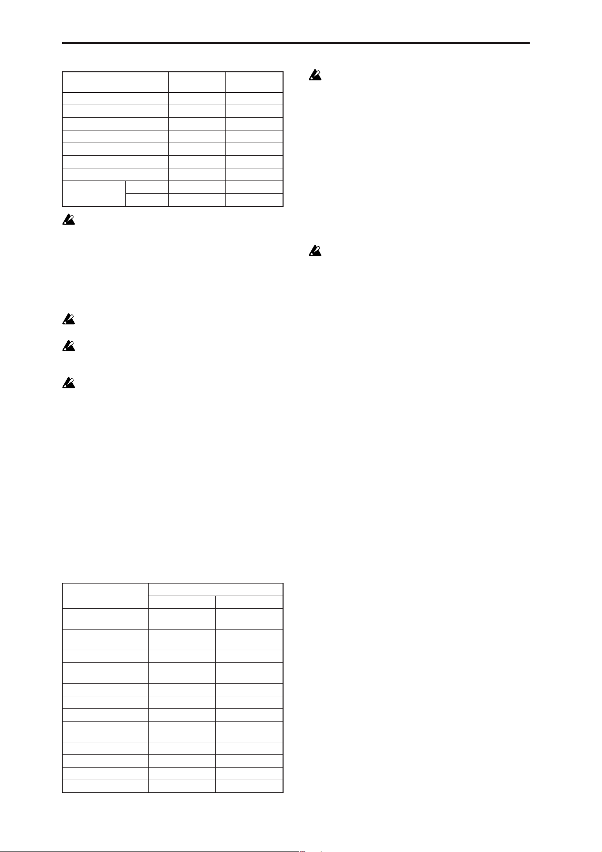
Type of data dumped
Drum Kit All 188 48.1
Drum Kit Single 4.7 0.4
Arpeggio Pattern All 91.8 23.5
Arpeggio Pattern Single 0.4 0.1
microX: Ext. Control Setup All 2.9 0.8
microX:
Ext. Control Setup Single
Global Setting 1.0 0.3
All
X50 957.8 245.2
microX 1025.6 262.6
Data size
(kByte)
0.1 0.0
Time required
(Sec)
When you save data dumps from this instrument to a
MIDI data filer, do not save multiple data dumps
together. If this data is saved together, there will be
insufficient time for this instrument to write each
received portion into memory before the next portion of
data arrives, so that it will be impossible to receive all of
the data correctly.
Reception
Do not touch this instrument’s switches or turn off the
power while data is being received.
Before receiving data, we recommend that you close the
various dialog boxes, page menus, or utility commands.
After a data dump is received, this instrument will
require up to 20 seconds to process the data and write it
into memory . During this time, the display will indicate
“Now writing into internal memory.” While this display is shown, you must under no circumstances turn
off the power of this instrument. If the power is turned
off during this time, this instrument may fail to operate
correctly when the power is turned on again. If this
occurs, hold down the [EXIT/CANCEL] button and the
[PAGE +] button while you turn on the power. However when this is done, the contents of memory will be
initialized.
Transmission and reception of MIDI data is also impossible during this time. When receiving multiple data
dumps in succession, you must allow an interval
between the transmission of each data dump. (☞refer
to the table below)
While this instrument is writing the data into memory,
transmission of Active Sensing (FEh) messages from the
MIDI OUT connector or USB connector will stop.
Data dump reception procedure
1 Connect this instrument and the device that will receive
the data dump.
If you’re using a computer that is able to transmit MIDI
exclusive messages, connect the computer’s USB connector to the X50/microX’s USB connector. Alternatively,
connect the MIDI OUT connector of your computer’s
MIDI interface to the X50/microX’s MIDI IN connector
(☞p.171).
If you are using a MIDI data filer, connect the MIDI OUT
connector of the data filer to the MIDI IN connector of
this instrument.
Some USB-MIDI interface devices may not be able to
transmit or receive the X50/microX’s MIDI exclusive
messages.
2 Set the MIDI channel of the MIDI device to match the
global MIDI channel “MIDI Channel” (1–1a) of this
instrument. If data that was previously transmitted to the
MIDI device is now going to be received again by this
instrument, set the global MIDI channel of this instrument to the same global MIDI channel setting that was
used when transmitting the data.
To set the MIDI channel of the transmitting device, refer
to the owner’s manual for that device.
3 Turn check the “Exclusive” setting (1–1b).
4 Transmit the data from the other device. For the proce-
dure, refer to the owner’s manual for the device you are
using. While the data is being received, the display will
indicate “Now received MIDI data.”
84
Processing time for writing into memory
Type of data dumped
All Approximately 3
All Programs Approximately 2
One Program Bank Less than 1second Less than 1second
All Combinations Approximately 1
One Combination Bank Less than 1second Less than 1second
All Multi Less than 1second Less than 1second
One Multi Less than 1second Less than 1second
All Drum Kits Approximately 1
All Arpeggio Patterns Less than 1second Less than 1second
microX:
All Ext. Control Setup
microX: 1 Ext. Control Setup
Global Setting Less than 1second Less than 1second
Processing time for writing into memory
X50 microX
seconds
seconds
second
second
— Less than 1second
— Less than 1second
Approximately 3
seconds
Approximately 2
seconds
Approximately 1
second
Approximately 1
second
Page 92

GLOBAL 2: User Scale
Here you can create sixteen User Octave Scales and one User
All Notes Scale. The user scales you create here can be
selected in the PROG 1–1, COMBI 2–4, MULTI 2–7(8).
If you wish to keep an edited user scale after the power
is turned off, be sure to write (save) your settings.
This data is written by the Utility “Write Global Setting.”
Stretch can be selected only if “To” is the User All Notes
Scale.
3 Select the copy destination scale (“To”).
4 To execute the Copy Scale command press the [MENU/
OK] button. To cancel, press the [EXIT/CANCEL] button.
2–2: All Notes
2–1: Octave
2–1a
2–1a: User Octave Scale
User Octave [00...15]
Select the user octave scale that you wish to edit.
Tune [–99…+99]
Specifies the scale for one octave of notes.
When you adjust the pitch of each note in the octave (C–B)
in one-cent steps, your settings will be applied to all octaves.
This adjustment is relative to equal temperament.
A setting of –99 lowers the pitch approximately a semitone
below normal pitch.
A setting of +99 raises the pitch approximately a semitone
above normal pitch.
Use the ClickPoint [√][®] to select the note whose pitch
you want to change.
X50: The note can also be selected by holding down the
[ENTER] button and playing a note on the keyboard.
■ 2–1: UTILITY
2–2a
2–2a: User All Notes Scale
Tune [–99…+99]
Here, you can make independent pitch settings for each of
the 128 notes.
Adjust the pitch of each of the 128 notes (C–1 – G9) in onecent steps. This adjustment is relative to equal temperament.
A setting of –99 lowers the pitch approximately a semitone
below normal pitch.
A setting of +99 raises the pitch approximately a semitone
above normal pitch.
In the case of the “User All Notes Scale,” you can select
Stretch in the Utility menu command “Copy Scale” (2–1b).
Use the ClickPoint [√], [®] to select the note that you wish
to set.
X50: You can also select the note by holding down the
[ENTER] button and playing a note on the keyboard.
Key Select [C–1...G9]
This indicates the location of the key displayed in “Tune.”
You can use the ClickPoint [π][†] to select a key graphic,
and use [√][®] to move it in one-octave units.
“Tune”
Indicates that there
are keys to the left.
Indicates that there
are keys to the right.
GLOBAL
0
123456
☞ “Write Global Setting” (0–1)
For details on how to select the desired utility function, refer
to “PROG 0–1: UTILITY.”
Copy Scale
This command copies a preset scale or user scale to the user
scale that you wish to edit. For details on the preset scales,
refer to “Type” (PROG 1–1c).
1 Select “Copy Scale” to access the dialog box.
2 Select the copy source scale (“From”).
If you select Pure Major or Pure Minor, you must also
specify the “Key” selection located at the right.
Key Select
■ 2–2: UTILITY
☞ “Write Global Setting” (0–1), “Copy Scale” (2–1)
85
Page 93

GLOBAL 3: Category
GLOBAL 4: DKit (Drum Kit)
Name
3–1: P.0..7 (Prog.00...07) 3–2: P.8..15 (Prog.08...15) 3–3: C.0..7 (Comb.00...07) 3–4: C.8..15 (Comb.08...15)
Here you can rename the categories for programs and combinations. Use the ClickPoint [√][®][π][†] to select the
category you want to rename, press the center of the ClickPoint to open the text dialog box, and enter the desired
name. You can enter up to sixteen characters. (☞OG X50:
p.112, microX: p.114).
With the factory settings, these are classified by type of
instrument.
You can specify sixteen categories each for programs and
combinations.
The category names you edit here can be specified
when you write data in the “Write Pr ogram dialog box”
(PROG 0–1: UTILITY) or “Write Combination dialog
box” (COMBI 0–1: UTILITY), and used in the respective
“Select by Category” function to select programs or
combinations by category.
3–1a
Here you can create a drum kit by assigning a drum instrument (drumsample) to each key.
A drum kit you edit here can be selected in Program mode
PROG 1: Ed–Basic OSC1 page “Drum Kit” (when “Oscillator
Mode” is Drums) as an oscillator, and pr ocessed through the
filter, amp and effects in the same way as a “multisample”
(when “Oscillator Mode” is Single or Double).
When you wish to edit a drum kit, enter Program mode,
select a program that uses a drum kit (i.e., whose “Oscillator
Mode” is Drums), and then move to this page. A program
that uses a drum kit will already have filter, amp, and effect
settings etc. suitable for drum sounds.
Even if a program with an “Oscillator Mode” of Single or
Double is selected in Program mode, the program will
sound using its own filter and amp settings etc. Effects will
sound according to the settings of the program you selected.
You must set “Octave” (PROG 1–2c) to +0[8']. With any setting other than +0[8'], the key locations and drum sounds
will not correspond correctly.
If “Exclusive” (1–1b) is checked, the drum kit can be
edited using exclusive data.
When a drum kit is edited, all programs that use that
drum kit will be affected.
If you want the edited drum kit settings to be backed
up after you turn off the power, you must write them
into memory.
Select the Utility “Write Drum Kits” to access the Write
Drum Kits dialog box and press the [MENU/OK] button to write the edited settings.
☞ For details on creating a drum kit (☞OG p.107).
3–3a
If you want the edited user categories to be backed up
when the power is turned off, you must write them into
memory. Select the Utility “Write Global Setting” to
access the Write Global Setting dialog box and pr ess the
[MENU/OK] button to write the edited settings.
3–1 (...4)a: Category
Select the category name you want to edit, and edit it.
Use the ClickPoint [√][®][π][†] to select a category, press
the center of the ClickPoint to open the text dialog box, and
enter a category name of up to sixteen characters.
For the editing procedure (☞OG X50: p.112, microX: p.114).
■ 3–1 (...4): UTILITY
☞ “Write Global Setting” (0–1)
4–1: High (High Sample)
Here you can select a drum kit, assign High and Low drumsamples to each key, and set parameters for the High and
Low drumsamples.
4–1a
4–1b
4–1a: Drum Kit, Key, Assign, Level H,
Level L, Vel. SW L→H
Drum Kit
X50: [00(INT )...15(INT ), 16(User)...39(User)]
microX: [00(INT )...31(INT ), 32(User)...39(User)]
Selects the drum kit that you wish to edit.
If you wish to modify the drum kit name, use the “Rename
Drum Kit” Utility menu command.
86
Page 94

X50
00(INT) …15(INT) preload drum kits, for user drum kits
16(User)...39(User) for user drum kits
microX
00(INT) …31(INT) preload drum kits, for user drum kits
32(User)...39(User) for user drum kits
Key [C–1...G9]
Indicates the key to which you will assign a drumsample
(and its settings).
All 4: DKit parameters except for “Drum Kit” will apply to
the key you assign here.
Two drumsamples, High and Low, can be assigned to each
key, and you can switch between them by velocity as you
play.
X50: You can also select a key by holding down the
[ENTER] button and playing a note on the keyboard.
Assign [O ff, On]
On (checked): The drumsamples you assigned for High (4–
1b) and Low (4–2a) will sound. Normally you will check this
parameter.
Off (unchecked): The selected drumsamples will be invalid,
and the drumsamples of the key to the right will sound. At
this time, the pitch will be a semitone lower than the pitch of
the key to the right. Uncheck this parameter when you wish
to play a drumsample at differing pitches.
Level H (Level High) [–99...+99]
Level L (Level Low) [–99...+99]
Specifies the volume of the High and Low drumsamples.
Keys that are set to +99 will sound at a volume double that
of the amp level of the program that uses this drum kit. Keys
that are set to 0 will sound at the amp level of the program
that uses this drum kit.
Keys that are set to –99 will not sound.
Vel. SW L→H (Velocity SW Lo→Hi)[001...127]
Specifies the velocity value at which you will switch from
the Low drumsample to the High drumsample. Velocities
above this value will sound the High drumsample, and
velocities below this value will sound the Low drumsample.
If you do not wish to use velocity switching, set this to 001
and specify only the High drumsample (☞“Velocity SW
L→H” PROG 1–2(3)a).
X50: You can also select a key by holding down the
[ENTER] button and playing a note on the keyboard.
S.Ofs (Start Offset) [Off, On]
On (checked): The sample waveform will start playback
from a location later than the beginning of the drumsample
waveform. The location of the Start Offset is pre-determined
for each drumsample. This setting is not valid for drumsamples which have no Start Offset.
Off (unchecked): Playback will start from the beginning of
the drumsample waveform.
Rev (Reverse) [Off, On]
On (checked): The drumsample waveform will playback in
“one-shot” reverse. The location at which the reverse playback will start and end is pre-determined for each drumsample.
If the drumsample is already preset for reverse playback or reverse loop playback, checking this setting will
not change its playback direction.
This parameter will not change the playback direction
of a sample for which “Rev (Reverse)” is checked.
Trans (Transpose) [–64...+63]
Adjusts the pitch in semitone steps. +12 is one octave up,
and –12 is one octave down.
Tune [–99...+99]
Adjusts the pitch in one-cent steps.
–99 is a semitone lower, and +99 is a semitone higher.
Fc (Cutoff) [–64...+63]
Adjusts the cutoff frequency of the filter. The cutoff frequency for each key is determined by adding this value to
the filter “Frequency” (PROG 4–1b, 5–1b) of the program
that uses this drum kit.
Reso (Resonance) [–64...+63]
Adjusts the filter resonance. The filter resonance for each
key is determined by adding this value to the filter “Resonance” (PROG 4–1b, 5–1b) of the program that uses this
drum kit. (When the “Type” (PROG 4–1a, 5–1a) is Low Pass
& High Pass, there will be no resonance effect.)
At (Attack) [–64...+63]
Adjusts the attack time of the volume (Amplifier). The
attack time for each key is determined by adding this value
to the amp EG Attack Time of the program that uses this
drum kit.
Dc (Decay) [–64...+63]
Adjusts the decay time of the volume (Amplifier). The decay
time for each key is determined by adding this value to the
amp EG Decay Time of the program that uses this drum kit.
GLOBAL
0
123456
4–1b: High (High Sample)
Drumsample X50: [000…517: name]
microX: [000...928: name]
Indicates the High drumsample. The sample selected here
will be sounded by velocities above the “Vel. SW L→H”
value.
You can use the utility menu command “Select by Category” to select drumsamples by category (☞4–1d).
It is not possible to edit the category name of a drumsample, or to re-specify its category.
■ 4–1: UTILITY
For details on how to select the desired utility function, refer
to “PROG 0–1: UTILITY.”
87
Page 95

Write Drum Kits
This command writes all drum kits 00 (INT)–48 (User).
1 Select “Write Drum Kits” to access the dialog box.
2 To execute the Write command press the [MENU/OK]
button. To cancel, press the [EXIT/CANCEL] button.
4–2: Low (Low Sample)
4–2a
Rename Drum Kit
This command renames the selected drum kit. You can input
a name of up to sixteen characters. (☞OG X50: p.112, microX:
p.114)
Copy Drum Kit
This command copies the settings of another drum kit to the
currently-edited drum kit. Drum kits 40 (GM)–48 (GM) cannot be edited, but you may copy them to another drum kit
and then edit them.
1 Select “Copy Drum Kit” to access the dialog box.
2 Select the copy source drum kit (“From”).
3 To execute the Copy Drum Kit command press the
[MENU/OK] button. To cancel, press the [EXIT/CANCEL] button.
Copy Key Setup
This command copies the settings of an individual key to
another key. You can also copy settings from two or more
contiguous keys at once.
1 Select “Copy Key Setup” to access the dialog box.
4–2a: Low (Low Sample)
Drumsample X50: [000…517: name]
microX: [000...928: name]
Selects the Low drumsample. This will be sounded by velocities lower than the value set for “Vel. SW L→H” (4–1a).
The drumsample can be selected using the utility menu
command “Select by Category” (☞4–1).
S.Ofs (Start Offset) [Off, On]
Rev (Reverse) [Off, On]
Trans (Transpose) [–64...+63]
Tune [–99...+99]
Fc (Cutoff) [–64...+63]
Reso (Resonance) [–64...+63]
At (Attack) [–64...+63]
Dc (Decay) [–64...+63]
☞ “High Drumsample” (4–1b)
■ 4–2: UTILITY
☞ “Write Drum Kits,” “Rename Drum Kit,” “Copy Drum
Kit,” “Copy Key Setup,” “Select by Category” (4–1)
4–3: V oice (Voice/Mixer)
For each key of a drum kit, you can set voice assign, pan,
and effect routing etc.
88
2 Specify the beginning of the range of keys to be copied
(“From Key”).
3 Select the copy destination key (“To Key”).
If you selected multiple keys in “From Key,” they will be
copied sequentially, starting at “To Key” and extending
upward.
4 To execute the Copy Key Setup operation, press the
[MENU/OK] button. To cancel, press the [EXIT/CANCEL] button.
Select by Category
You can select drumsamples by category.
All drumsamples are grouped into one of sixteen categories.
For the procedure, refer to “Select by Category” (☞p.2)
It is not possible to edit the name of a drumsample category or to change the assigned category of a drumsample.
4–3a
4–3a: Voice Assign Mode/Mixer
Voice Assign Mode:
Single Trig (Single T rigger) [Off, On]
On (checked): Even when the same key (note) is played
repeatedly, the previous note will be halted before the new
note is begun, so that the notes will not overlap. Normally
you will leave this unchecked.
Excl Group (Exclusive Group) [Off, 001...127]
001–127: This allows you to group keys to which a drumsample is assigned. Keys to which the same group number
is assigned will be treated as a single group, and will be
Page 96

played monophonically with last-note priority. For example
you might assign closed and open hi-hat sounds to the same
group so that two or more hi-hat sounds can not sound
simultaneously.
Off: Keys will not be grouped. Normally you will set this
Off.
Enable Note On (Note On Receive)
On (checked): Note-on messages will be received.
Normally you will check this, but you can uncheck it if you
do not want specific notes to sound.
Enable Note Off (Note Off Receive)
On (checked): Note-off messages will be received.
Normally you will uncheck this. This parameter is valid
when “Hold” (PROG 1–1b) is checked (Hold On). In the
case of a drum program, you will normally select Hold On.
In this case if “Enable Note Off” is checked, note-off messages will be received, and the sound will stop (the release
segment of the EG will begin) when the key is released.
Mixer:
Pan [Rndm, L001...C064...R127]
Specifies the panning for each key.
With a setting of Rndm (Random), the panning of the drumsample will change randomly for each note-on.
BUS (Bus Select) [L/R, IFX, 1, 2, 1/2, Off]
Specifies the bus to which each key will be sent.
For example you can send snare-type sounds to IFX to apply
the insert effect, and send the other sounds to L/R without
applying the insert effect.
S1 (Send1 (MFX1)) [000...127]
S2 (Send2 (MFX2)) [000...127]
For each key, specify the send levels to master effects 1 and
2. These settings are valid when “BUS Select” (4–3a) is set to
L/R or Off.
If “BUS Select” is set to IFX, the send level to master effects 1
and 2 will be determined by the Program, Combination, or
Multi mode Setup pages (PROG/COMBI 8–2, MULTI 8–3)
“S1 (Send1(MFX1),” “S2 (Send2(MFX2)” which are located
after the sound passes through IFX.
Drum kits will sound using the settings of the program
that is selected in Program mode. These settings are
valid only if “Use DKit Setting” (PROG 6–1b, 8–1b) are
checked. Be aware that the results of editing a drum kit
will not be reflected unless these settings have been
made in the program.
GLOBAL 5: Arp.Pattern
Here you can create user arpeggio patterns.
In this page, the X50/microX will sound as it did in the
mode you were in before entering Global mode.
If you entered the Global mode from Program mode: Your
editing will apply to the arpeggio pattern that is selected by
the program. Even if you moved from a program in which
the arpeggiator is turned off, it can be turned on by the [ARP
ON/OFF] button.
If you entered the Global mode from Combination mode:
Your editing will apply to the arpeggio pattern that is
selected by the combination. Even if you moved from a combination in which the arpeggiator is turned off, it can be
turned on by the [ARP ON/OFF] button.
However, it is not possible to turn on an arpeggiator for
which the A or B parameter is unchecked in “Arpeggiator
Run” (COMBI 0–4(5)a, COMBI 7–1a). Also, the arpeggiator
will not run unless it has been assigned to a timbre in
“Assign” (COMBI 7–1b).
If you entered the Global mode from Multi mode: Your
editing will apply to the arpeggio pattern specified for the
selected multi set.
Even if you entered Global mode from a mode in which the
arpeggiator was turned off, you can use the [ARP ON/OFF]
button to turn it on. However, it is not possible to turn on an
arpeggiator for which the “Arpeggiator Run” (MULTI 7–
1(2)a) parameter A or B is not checked. Also, the arpeggiator
will not operate if it has not been assigned to a track in
“Assign” (MULTI 7–1(2)b).
In each of the above cases, you can modify the settings of the
arpeggio pattern even if the arpeggiator is not turned on.
When editing a pattern, it is a good idea to turn on the
arpeggiator and make sure that it is the pattern that you
wish to edit.
If you want the edited user arpeggio pattern settings to
be backed up even when the power is turned off, you
must write them into memory. Select the Utility “Write
Arpeggio Pattern” to access the Write Arpeggio Pattern
dialog box.
☞ For details on creating an arpeggio pattern (☞OG p.91).
5–1: Setup
5–1a
5–1b
5–1c
GLOBAL
0
123456
■ 4–3: UTILITY
☞ “Write Drum Kits,” “Rename Drum Kit,” “Copy Drum
Kit,” “Copy Key Setup” (4–1)
5–1d
5–1a: Arp, Pat (Pattern), (Tempo)
Arp (Arpeggio Select) [A, B]
If you have moved from Combination mode or Multi mode
and edit an arpeggio pattern, you must select either
arpeggiator A or B as the pattern to edit. Your editing will
apply only to the selected one.
B will not be displayed if you moved here from Program
mode.
89
Page 97

Pat (Pattern)
[Preset-0...Preset-4, U000...U250]
Selects the pattern that you wish to edit.
Preset-0…Preset-4 Preset Arpeggio Patterns
U000...250 Preload user Arpeggio Patterns
(Tempo) [040...240, EXT]
This specifies the tempo.
This can also be adjusted by the REALTIME CONTROLS Cmode [TEMPO] knobs.
If “MIDI Clock” (1–1a) is set to Ext-MIDI or Ext-USB, or set
to Auto and operating as a slave, this will indicate EXT, and
the arpeggiator will synchronize to MIDI clock messages
from an external MIDI device.
5–1b: Lgth, Reso, Oct, Sort, Latch, K.Sync,
Kbd
Lgth (Length) [01...48]
This specifies the length of the arpeggio pattern. After the
note value specified by “Reso” occurs for the number of
times specified here, the pattern will return to the beginning.
This parameter is not valid for preset patterns Preset-0–Pre-
set-4.
Reso (Resolution) [ , , , , , ]
Oct (Octave) [1, 2, 3, 4]
Sort [Off, On]
Latch [Off, On]
K.Sync (Key Sync.) [Off, On]
Kbd (Keyboard) [Off, On]
☞ PROG 7: Ed–Arp/Ctrls “Setup(Arpeg. Setup)”
“Pat,” “ (Tempo),” “Oct,” “Reso,” “Sort,” “Latch,”
“K.Sync,” and “Kbd” are parameters that can be set in
Program, Combination, multi set, but you can also set
them here.
If you move here from Program or Combination mode
and set these parameters, you must return to the original mode and write them. These parameters cannot be
written by the “Write Arpeggio Patterns” command in
this page.
Up&Down: If there are more Tones in a step than arpeggio
notes specified (notes played on the keyboard), the arpeggio
will return in reverse direction from the last arpeggio note
back toward the first.
Example)
If you set “Lgth” to 04, “Step” 01 to Tone0, “Step” 02 to
Tone1,” “Step” 03 to Tone2, “Step” 04 to Tone3, and
simultaneously play three notes to produce an arpeggio,
the following results will be produced depending on the
“Type.”
As Played: 0 → 1 → 2 → rest → 0 → 1 → 2 → rest → 0 ...
As Played (Fill): 0 → 1 → 2 → 2 → 0 → 1 → 2 → 2 → 0 ...
Running Up: 0 → 1 → 2 → 0 → 0 → 1 → 2 → 0 → 0 ...
Up&Down: 0 → 1 → 2 → 1 → 0 → 1 → 2 → 1 → 0 ...
Octave Motion [Up, Down, Both, Parallel]
Specifies the operation when “Oct” is set to 2–4 octaves.
Up: Notes will repeatedly ascend within the specified range
of octaves.
Down: Notes will repeatedly descend within the specified
number of octaves.
Both: Notes will repeatedly ascend and descend within the
specified number of octaves.
Parallel: The notes of the specified octaves will sound simultaneously.
5–1d: Fixed Note, Mode, Tone No., Fixed
Note No.
Fixed Note [Off, On]
Specifies the Tone type (the “●” or “❍” displays in 5–2) of
the arpeggio pattern.
Off (unchecked): This is the normal arpeggiator type. The
Tone pitches will be expanded into an arpeggio based on the
note number played on the keyboard.
On (checked): You can specify the note number for each
Tone. The note numbers from the keyboard will be ignored
for the purposes of the Tone pitch, and the arpeggio will be
sounded using the note numbers specified for each Tone.
The note numbers from the keyboard will only control the
timing at which the arpeggiator is triggered. This setting is
suitable for arpeggio patterns used for drum patterns etc.
The Tone indication in 5–2: Arp.Pattern, Edit page will be
“
●” if this setting is Off (unchecked), or “❍” if this is On
(checked).
90
5–1c: Arpeggio Pattern Setup
These parameters are not valid for preset patterns Preset-0–Preset-4.
Type (Arpeggio Type)[As Played...Up&Down]
This specifies the correspondence between the arpeggio
notes specified from the keyboard and the Tone at each step.
As Played: If there are more Tones in a step than arpeggio
notes specified (notes played on the keyboard), those steps
will not sound.
As Played (Fill): If there are more Tones in a step than
arpeggio notes specified (notes played on the keyboard), the
last arpeggio note (the last-played note if “Sort” is Off, or
the highest note if “Sort” is On) will sound for those steps.
Running Up: If there are mor e Tones in a step than arpeggio
notes specified (notes played on the keyboard), the arpeggio
will return to the first note (the first-pressed note if “Sort” is
Off, or the lowest note is “Sort” is On) and sound it.
Mode (Fixed Note Mode)
[Trigger As Played, Trigger All Tones]
Specifies how tones will be triggered when “Fixed Note” is
checked.
Trigger As Played: The Tones will be triggered according to
the number of keys pressed.
Trigger All Tones: Pressing a single key will trigger all
Tones.
Example)
Here’s how the drums pattern will sound when “Fixed
Note” is checked. Tone 1 is assigned a note number that
plays a kick sound, Tone 2 a snare, and Tone 3 a hi-hat.
With a setting of Trigger As Played, pressing one key
will sound only Tone 1 (kick). Pressing two keys will
sound Tone 1 (kick) and Tone 2 (snare). Pressing three
keys will sound all three Tones 1–3 (kick, snare, hi-hat). If
the “Vel (Velocity)” of each Tone is set to Key, each Tone
will be sounded at the velocity with which each key was
played.
Page 98

With a setting of Trigger All Tones, playing one key is
sufficient to sound all three; Tone 1 (kick), Tone 2 (snare),
and Tone 3 (hi-hat). If the “Vel (Velocity)” of each Tone is
set to Key, the Tones will be sounded at the correspond-
ing velocity each time a key is pressed.
3 To execute the Copy Arpeggio Pattern command press
the [MENU/OK] button. To cancel, press the [EXIT/
CANCEL] button.
Tone No. [00...11]
This is valid only if “Fix Note” (5–1d) is checked. It selects
the Tone.
Fixed Note No. [C–1...G9]
Specifies the note number for the selected Tone.
X50: You can also input this value by holding down the
[ENTER] button and pressing a note on the keyboard.
■ 5–1: UTILITY
For details on how to select the desired utility function, refer
to “PROG 0–1: UTILITY.”
Write Arpeggio Patterns
This command writes user arpeggio patterns U000–U250.
1 Select “Write Arpeggio Patterns” to access the dialog box.
2 To execute the Write command press the [MENU/OK]
button. To cancel, press the [EXIT/CANCEL] button.
“Pat,”“ (Tempo),” “Oct,” “Reso,” “Sort,” “Latch,”
“K.Sync,” and “Kbd” are parameters that are set in Program, Combination, and Multi modes. The Write operation executed here does not save these parameters.
If you move here from Program or Combination mode
and set these parameters, you must return to the original mode and write them.
Rename Arpeggio Pattern
This command renames the selected user arpeggio pattern.
Up to sixteen characters can be input. Preset patterns Preset0–Preset-4 cannot be selected (☞OG X50: p.112, microX:
p.114).
Copy Arpeggio Pattern
This command copies the settings of another user arpeggio
pattern to the currently selected arpeggio pattern. It is not
possible to copy from a preset arpeggio pattern Preset-0–
Preset-4.
1 Select “Copy Arpeggio Pattern” to access the dialog box.
5–2: Edit
Here you can input Tones 0–11 for each step 01 to 48. “Step”
can be a maximum of 48 steps, and Tone corresponds to up
to twelve notes for the (up to) twelve keys pressed simultaneously. If “Sort” (5–1b) is checked, the notes that were
pressed will correspond in ascending order of pitch to Tones
0, 1, etc. If “Sort” (5–1b) is unchecked, the notes that were
pressed will correspond to Tones 0, 1, etc. in the order in
which they were pressed.
These parameters are not valid for preset patterns Preset-0–Preset-4 .
5–2a
5–2a: Step, Ptch, Gt, Vel, Flam
Step (Step No.) [01...48]
Select the step that you wish to edit, and set/reset each
Tone. With “Step” selected, press the center of the ClickPoint, use ClickPoint [π][†] to select the Tone you want to
enter, and press the center of the ClickPoint to confirm your
selection. Use the ClickPoint [√][®] to move to another
step.
When you’re finished with entry , pr ess the [EXIT/CANCEL]
button or the [MENU/OK] button.
You can use the “Delete Step” utility to delete the Tones of
all steps, or the “Insert Step” utility to insert an empty step.
X50: Use the numeric buttons to enter Tones. With “Step”
selected, use the numeric buttons to enter a T one. [0]–[9] cor respond to Tone 0–9, [–] to Tone 10, and the [./HOLD] but-
ton to Tone 11. The tone will be set or reset each time you
press the button.
Tones are shown as “❍” if “Fixed Note” (5–1d) is checked,
or as “●” if it is not checked.
Ptch (Pitch Offset) [–48...+48]
For each step, the pitch corresponding to the Tone can be
raised or lowered in semitone steps. This lets you make settings for the same tone in each step to create a melody, or to
make settings for two or more tones in each step to play parallel chords.
GLOBAL
0
123456
2 Select the copy source arpeggio pattern “From.”
91
Page 99

Gt (Gate) [Off, 001...100%, LGT ]
Off: That step will not sound even if Tones have been specified.
LGT: Notes will continue sounding until the same Tone is
sounded next, or until the pattern returns to the beginning.
At this time, the display will change to “
This setting is valid when the Program, Combination, or
multi set parameter “Gate” (PROG 7–1a, COMBI 7–2(3)a,
MULTI 7–3(4)a) is set to Step. When making this setting,
make sure that “Gate” is set to Step in the mode from which
you arrived here.
■” or “ .”
Vel (Velocity) [001...127, Key]
Key: The Tone of the step will sound with the velocity at
which the key was played.
001–127: The specified velocity value will always be used.
This setting is valid when the Program, Combination, or
Multi set parameter “V elocity” (PROG 7–1a, COMBI 7–2(3)a,
MULTI 7–3(4)a) is set to Step.
When making this setting, make sure that “Velocity” is set to
Step in the mode from which you arrived here.
Flam [–99...+99]
Specifies how the note timing will be skewed when two or
more Tones are specified in the same step. To simulate
chords strummed on a guitar, it is effective to set “+” values
for odd-numbered steps and “–” values for even-numbered
steps.
This setting is not valid for preset patterns Preset-0 thru Preset-4.
00: All Tones will sound simultaneously.
+01–+99: The timing of the notes will be skewed in the order
of the Tone number. (When “Sort” is ON, from low note to
high note. When “Sort” is OFF, in the order in which keys
were pressed.)
–01– –99: The timing of the notes will be skewed in the
opposite direction as “+.”
■ 5–2: UTILITY
Copy Step
This command copies the settings of a specific step. The settings of two or more adjacent steps can also be copied
together.
1 Select “Copy Step” to access the dialog box.
2 Select the range of steps that you wish to copy (“From
Step”).
3 Select the copy destination step “To Step”.
If you selected more than one step in “From Step,” the
steps will be copied starting at “To Step” and continuing
through the steps to the right.
4 To execute the Copy Step command, press the [MENU/
OK] button. To cancel, press the [EXIT/CANCEL] button.
Delete Step
This command deletes the step parameters (“Tone,” “Ptch,”
“Gt,” “Vel,” “Flam”) of the currently selected step number.
Subsequent steps will move one column toward the left.
1 Select “Delete Step” to access the dialog box.
2 To execute the Delete Step operation, press the [MENU/
OK] button. To cancel, press the [EXIT/CANCEL] button.
Insert Step
This command inserts an empty step into the currently
selected step number. Subsequent steps will be moved one
step to the right.
1 Select “Insert Step” to access the dialog box.
92
☞ “Write Arpeggio Patterns,” “Rename Arpeggio Pattern,”
“Copy Arpeggio Pattern” (5–1)
For details on how to select the desired utility function, refer
to “PROG 0–1: UTILITY.”
Initialize Steps
This command initializes the step parameters (“Tone,”
“Ptch,” “Gt,” “Vel,” “Flam”) of the arpeggio pattern.
1 Select “Initialize Steps” to access the dialog box.
2 Select the type “Type” of initialize.
Empty will initialize all tones to a blank state. Full will
initialize all tones to a full state.
3 To execute the Initialize Steps operation, press the
[MENU/OK] button. To cancel, press the [EXIT/CANCEL] button.
2 To execute the Insert Step operation, press the [MENU/
OK] button. To cancel, press the [EXIT/CANCEL] button.
Rotate Step
This command rotates the step settings.
1 Select “Rotate Step” to access the dialog box.
2 Select the type “Direction” of rotation.
For example, suppose there is a pattern of “Length” 4.
If you select Forward, the settings of Step 1 will be
rewritten to 2, Step 2 →3, Step 3 →4, Step 4 → 1.
If you select Backward, the settings of Step 1 will be
rewritten to 4, Step 2 → 1, Step 3 → 2, Step 4 → 3.
3 To execute the Rotate Step operation, press the [MENU/
OK] button. To cancel, press the [EXIT/CANCEL] button.
Page 100

microX:
GLOBAL 6: Ext. Control
External Control lets you use the REALTIME CONTROL
knobs to control external MIDI devices. You can assign a
MIDI control change and MIDI channel to each of the four
knobs, and switch between three such settings (A, B, C) to
control an external device. This means that each set-up lets
you transmit twelve (4 × 3) different MIDI control changes.
(☞p.5)
You can select and use these setups if EXT. CONTROLLER is
turned on in Program, Combination, or Multi Set modes.
You can create 64 different external control setups. For
example you might use one setup to control one of the
KORG Legacy Collection soft synthesizers, and another
setup to control the level or pan parameters of your DAW
(Digital Audio Workstation).
External Control gives you a set of independent control
functions that you can use via the microX’s knobs while in
any mode.
Switching programs or moving to Combination mode while
the [EXT. CONTROLLER] button is on will not change the
external control set that is selected. This means that you can
select microX sounds without affecting your external MIDI
control setup, or conversely, change the external MIDI control setup without switching sounds.
After you’ve edited a external control set, you’ll need to
execute the “Write Ext. Control Set” utility to write
(save) the edited settings.
6–1: A (Knob 1–A, 2–A, 3–A, 4–A)
6–2: B (Knob 1–B, 2–B, 3–B, 4–B)
6–3: C (Knob 1–C, 2–C, 3–C, 4–C)
6–1(2)(3)b: Knob 1A–1C, Knob 2A–2C,
Knob 3A–3C, Knob 4A–4C
MIDI Channel [01...16, Gch]
This specifies the MIDI channel on which each knob [1]–[4]
will transmit messages when [SELECT] A (B, C) is selected.
Gch: Messages will be transmitted on the global MIDI channel specified in Global mode. You can easily change the
channel of all the knobs that are set to Gch simply by changing the global MIDI channel setting, instead of changing the
channel of each knob individually.
CC Assign [Off, 000...119]
This specifies the MIDI control change number that each
knob [1]–[4] will transmit when [SELECT] A (B, C) is
selected.
■ 6–1(2)(3): UTILITY
For details on how to select the desired utility function, refer
to “PROG 0–1: UTILITY.”
Write Ext. Control Setups
Here’s how to write external control setups 00–63.
1 Select “Write Ext. Control Setups” to access the dialog
box.
2 Press the [MENU/OK] button to write the data. If you
decide not to execute, press the [EXIT/CANCEL] button.
Reset Ext. Control Setup
Here’s how to rename the selected external control setup.
You can enter up to sixteen characters. (☞OG X50: p.112,
microX: p.114)
GLOBAL
0
123456
6–1a
6–1b
6–1(2)(3)a: Knob A–B
Ext. Control (Setup Select) [00...63]
Selects the external control setup that you want to edit.
Reset Ext. Control Setup
Here’s how to initialize an external control setup.
All settings of the selected setup will be initialized as follows.
• “MIDI Channel” = Gch
• “CC Assign” = Off
1 Select the external setup that you want to initialize.
2 Select “Reset Ext. Control Setup” to access the dialog box.
3 Press the [MENU/OK] button to initialize the settings. If
you decide not to execute, press the [EXIT/CANCEL]
button.
93
 Loading...