

Page 1
Operation Guide
Operation Guide
1E
Page 2
Precautions
Location
Using the unit in the following locations can result in a malfunction.
• In direct sunlight
• Locations of extreme temperature or humidity
• Excessively dusty or dirty locations
• Locations of excessive vibration
• Close to magnetic fields
Power supply
Please connect the designated AC adapter to an AC outlet
of the correct voltage. Do not connect it to an AC outlet of
voltage other than that for which your unit is intended.
Interference with other electrical devices
Radios and televisions placed nearby may experience
reception interference. Operate this unit at a suitable distance from radios and televisions.
Handling
To avoid breakage, do not apply excessive force to the
switches or controls.
Care
If the exterior becomes dirty, wipe it with a clean, dry cloth.
Do not use liquid cleaners such as benzene or thinner, or
cleaning compounds or flammable polishes.
Keep this manual
After reading this manual, please keep it for later reference.
Keeping foreign matter out of your equipment
Never set any container with liquid in it near this equipment. If liquid gets into the equipment, it could cause a
breakdown, fire, or electrical shock.
Be careful not to let metal objects get into the equipment. If
something does slip into the equipment, unplug the AC
adapter from the wall outlet. Then contact your nearest
Korg dealer or the store where the equipment was purchased.
THE FCC REGULATION WARNING (for U.S.A.)
This equipment has been tested and found to comply with
the limits for a Class B digital device, pursuant to Part 15 of
the FCC Rules. These limits are designed to provide reasonable protection against harmful interference in a residential installation. This equipment generates, uses, and
can radiate radio frequency energy and, if not installed and
used in accordance with the instructions, may cause harmful interference to radio communications. However, there is
no guarantee that interference will not occur in a particular
installation. If this equipment does cause harmful interference to radio or television reception, which can be determined by turning the equipment off and on, the user is
encouraged to try to correct the interference by one or more
of the following measures:
• Reorient or relocate the receiving antenna.
• Increase the separation between the equipment and
receiver.
• Connect the equipment into an outlet on a circuit different from that to which the receiver is connected.
• Consult the dealer or an experienced radio/TV technician
for help.
Unauthorized changes or modification to this system can
void the user’s authority to operate this equipment.
CE mark for European Harmonized Standards
CE mark which is attached to our company’s products of
AC mains operated apparatus until December 31, 1996
means it conforms to EMC Directive (89/336/EEC) and CE
mark Directive (93/68/EEC).
And, CE mark which is attached after January 1, 1997
means it conforms to EMC Directive (89/336/EEC), CE
mark Directive (93/68/EEC) and Low Voltage Directive (73/
23/EEC).
Also, CE mark which is attached to our company’s products
of Battery operated apparatus means it conforms to EMC
Directive (89/336/EEC) and CE mark Directive (93/68/
EEC).
• Apple, Mac and Audio Units are trademarks of Apple
Computer, Inc., registered in the US. and other countries.
• Windows XP is a registered trademark of Microsoft Corporation in the U.S. and other counties.
• VST is a trademark of Steinberg Media Technologies
GmbH.
•RTAS is a registered trademark of Avid Technology, Inc.,
or its subsidiaries or divisions.
• All other product and company names are trademarks or
registered trademarks of their respective holders.
ii
Page 3

Thank you for purchasing the Korg microX Synthesizer/Controller. To help you get the most out of
your new instrument, please read this manual carefully.
About this manual
The owner’s manuals and how to use
them
The microX come with the following owner’s
manuals.
• Operation Guide
• Parameter Guide (included in the CD-ROM)
Operation Guide
Please read this first. It explains the names and
functions of each part of the microX, how to make
connections, basic operation, an overview of each
mode, and how to edit sounds. This guide also
explains the arpeggiator function, effects, and
drum kits.
The Operation Guide also contains troubleshooting information, and supplemental information
such as specifications.
Parameter Guide
The Parameter Guide contains explanations and
other information regarding the operations of the
parameters and settings on the microX.
The explanations are organized by mode, and
page. Explanations and other information on the
effects and their parameters are also provided for
teach effect.
Refer to this guide when an unfamiliar parameter appears in the display, or when you need to
know more about a particular function.
Conventions in this manual
Abbreviations for the manuals OG, PG
In the documentation, references to the manuals
are abbreviated as follows.
OG: Operation Guide
PG: Parameter Guide
Procedure steps 1. 2. 3. …
This indicates the steps of a procedure.
Symbols , , Note
These symbols respectively indicate a caution, a
MIDI-related explanation, a supplementary note.
Example screen displays
The values of the parameters shown in the example screens of this manual are only for explanatory purposes, and may not necessary match the
values that appear in the LCD display of your
instrument.
MIDI-related explanations
CC# is an abbreviation for Control Change Num-
ber.
In explanations of MIDI messages,
square brackets [ ]
numbers.
always indicate hexadecimal
numbers in
iii
Page 4

Table of Contents
Precautions............................................................... ii
About this manual ....................................... iii
Quick Start.........................................1
Setup ......................................................................1
Playing programs and combinations................2
Listening to the demo songs...............................8
Introduction ......................................9
Main features ................................................ 9
Front and rear panel...................................11
Front panel..........................................................11
Rear panel............................................................14
Objects in the Display and their functions.....15
Basic Information........................................17
About the microX’ modes.................................17
Basic operations..................................................19
Setup................................................23
Turning the power on/off...........................23
Connecting the AC adapter..............................23
Turning the power on........................................23
Turning the power off .......................................24
Connections.................................................25
Basic connections................................................25
Connecting a damper pedal, foot switch,
or foot pedal........................................................26
Connecting a computer.....................................27
Connecting MIDI devices .................................35
Playing and Editing Programs.......37
Playing programs........................................37
Selecting programs ............................................37
Using Controllers...............................................40
Simple program editing.............................43
Performance Edit................................................43
REALTIME CONTROLS [1], [2], [3], [4],
[SELECT].............................................................43
Saving your edits................................................45
Detailed Editing with Programs ................46
Before you begin editing...................................46
Basic oscillator settings......................................48
Using LFOs and Envelopes (EGs)....................50
Using Alternate Modulation ............................51
Controlling Pitch................................................52
Using Filters........................................................53
Using the Amp section......................................55
Effects...................................................................56
Playing and Editing Combinations
Playing combinations.................................57
Selecting combinations......................................57
Using Controllers...............................................59
Simple combination editing ......................60
Changing the programs within the
Combination .......................................................60
Adjusting a timbre’s pan and volume ............60
REALTIME CONTROLS [1], [2], [3], [4],
[SELECT].............................................................61
Saving your edits................................................61
Detailed Editing with Combinations.........62
Before you begin editing...................................62
Selecting a program for each timbre ...............63
Status and MIDI settings...................................63
Layers, Splits, and Velocity switches ..............64
Altering Programs to fit within a
Combination .......................................................66
Effects...................................................................68
...57
iv
Page 5

Using and Editing Multi sets..........69
MIDI considerations ................................... 69
Selecting a multi set...........................................69
Assigning a program to a track, and setting
the volume and pan...........................................70
Copying the settings of a combination to a
multi set...............................................................72
What you can do in Multi mode......................73
Using Controllers...............................................74
Altering Programs to fit within a Multi set....74
Layers, Splits, and Velocity Switches..............75
Effects...................................................................75
Saving your edits................................................75
Control via MIDI................................................75
Effects settings............................... 79
Effects in each mode..........................................79
Effect types..........................................................79
Effect settings for a program............................81
Effect settings in combination, and Multi.......84
Dynamic modulation and BPM/MIDI Sync.
Saving edited effect settings.............................86
Bypassing the insert effect or the master
effects ...................................................................86
..85
Global Mode ...................................87
How Global mode is structured.......................87
System setup 0: System ...................................87
MIDI-related settings 1: MIDI........................89
Creating user scales 2: User Scale..................89
Setting category names
3: Category Name ..............................................90
Saving the global settings .................................90
Drum kit 4: DKit,
Arpeggiator 5: Arp.Pattern, External
Control 6: Ext.Control settings.......................90
Saving a user arpeggio....................................104
Synchronizing the arpeggiator.......................105
Using Drum Kits............................107
What is a Drum Kit? ........................................107
Before you start editing…...............................107
Editing Drum Kits............................................108
Saving a drum kit.............................................110
External control settings .............111
Using external controls....................................111
External control setups....................................112
Saving an external control setup....................112
Other functions ............................113
Restoring the factory settings (Loading the
preloaded data) ................................................113
Assigning a name (Rename)...........................114
Assigning functions to REALTIME
CONTROLS B-mode knobs [1]–[4]................115
Adjusting the display contrast.......................115
Tap tempo control............................................115
Appendices...................................117
Saving data ............................................... 117
Types of data that can be saved.....................117
About the Edit Buffer ......................................118
Troubleshooting....................................... 119
Specifications and options ...................... 122
Specifications....................................................122
Operating requirements for connection to a
computer ...........................................................123
Options ..............................................................123
MIDI Implementation Chart..................... 124
Arpeggiator settings......................91
Arpeggiator features in
Program mode....................................................91
The arpeggiator in Combination and Multi
modes...................................................................95
Creating a user arpeggio pattern.....................99
Index.......................................................... 126
v
Page 6

vi 1
Page 7
1.
2.
Quick Start
This Quick Start is provided for those who just want to get started trying out the sounds right
away.
It explains how to set up the microX, how to select programs and control the sound, and how to
listen to the demo songs.
After you’ve finished reading this Quick Start section, please also take a look at the full explanations that follow.
Setup
Make all your connections with the power off (on all units!). If you don’t, you may damage
your speaker system or damage your microX and/or other equipment
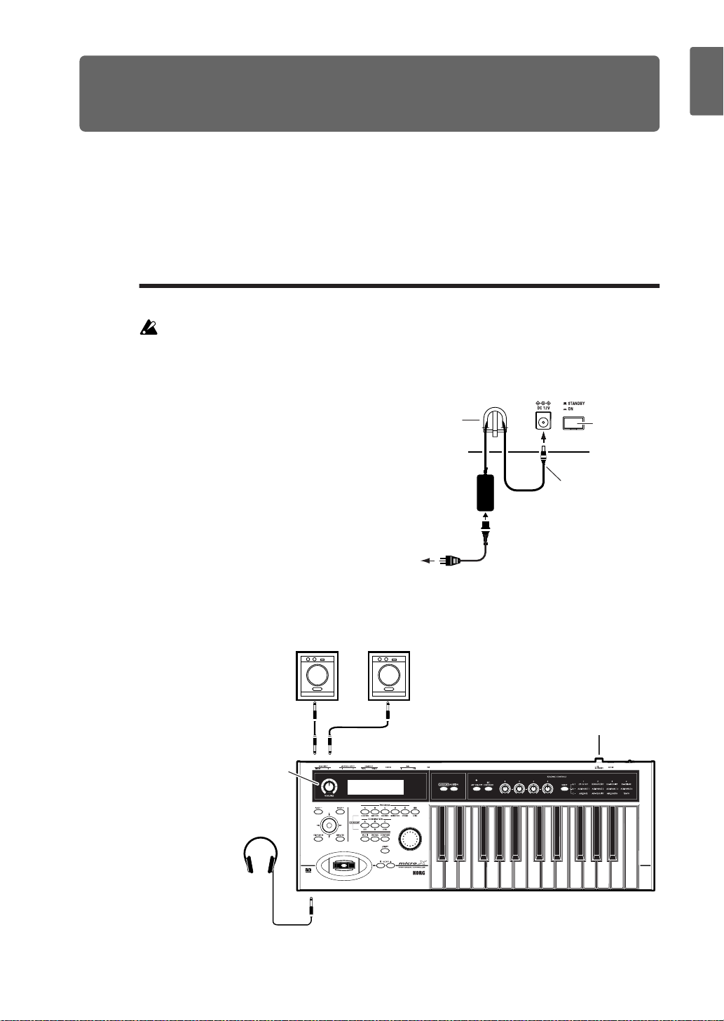
Connect the included AC adapter.
Use only the AC adapter included with
the microX. Do not use any other AC
adapter.
Connect the microX to your audio
monitoring system.
Using standard audio cables with 1/4"
phone plugs, connect the microX’ (MAIN
OUTPUT) L/MONO and R output jacks
to the input jacks of your mixer,
amplified monitor speakers, or audio
recording device.
If you’re listening through headphones,
connect them to the headphone jack
located on the left front of the microX.
The headphones produce the same signal
as the (MAIN OUTPUT) L/MONO and R jacks.
Connecting the AC adapter
4 Cable hook
AC adapter
2
Plug into an AC
outlet
3 Power cable
. Please use caution.
Power switch
1 Power connector
Be careful not to
bend this portion
excessively when you
wrap the cable
through the cable
hook.
Quick StartIntroductionSetupProgram
Combination
MultiEffectGlobalArpeggiatorDrum Kit
Audio output device
connections
Adjust the
[VOLUME] slider
Headphones
RL/MONO
PHONES
Powered
monitors
INPUTINPUT
Power switch
External control
Other functions
Appendices
Page 8
Quick Start
3.
4.
5.
1.
2.
Turn the microX’s [VOLUME] knob down (to the left).
Turn on your audio monitor system and set the volume to a normal level.
Turn on the microX by pressing the power switch located on the rear panel.
Slowly raise the microX’s [VOLUME] knob to an appropriate volume.
Playing programs and combinations
By default, Combination mode will be selected when you turn on the power.
Play the keyboard, and you will hear the sound of bank A combination number 000.
A combination consists of up to eight programs that are split, zoned, layered or velocityswitched across the keyboard. A combination can also use up to two Arpeggiators simultaneously (a program can use only one Arpeggiator), letting you produce far more complex
sounds than a single program.
Although you could simply continue selecting and playing differ ent combinations, let’s start by
selecting and listening to the “basic” sounds of the microX – programs.
Note: If you don’t hear any sound when you play the keyboard: Check the connections once
again. Also make sure that the micr oX’s VOLUME and the volume of your powered speakers or
stereo amp are turned up appropriately.
Selecting programs by bank and number
1, 4
2
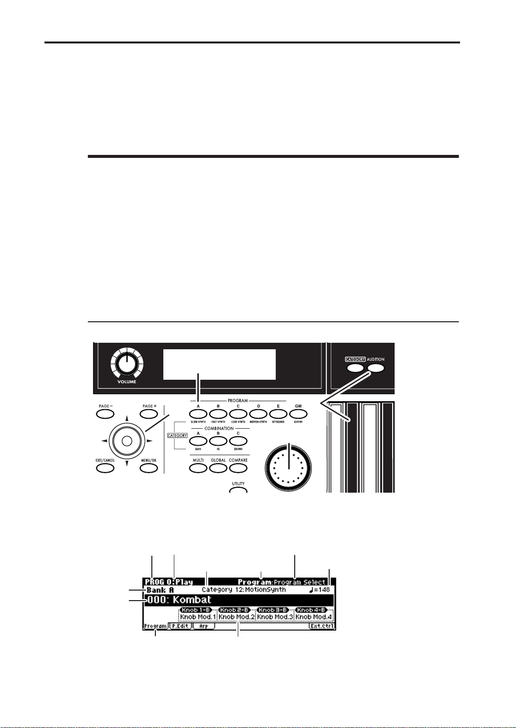
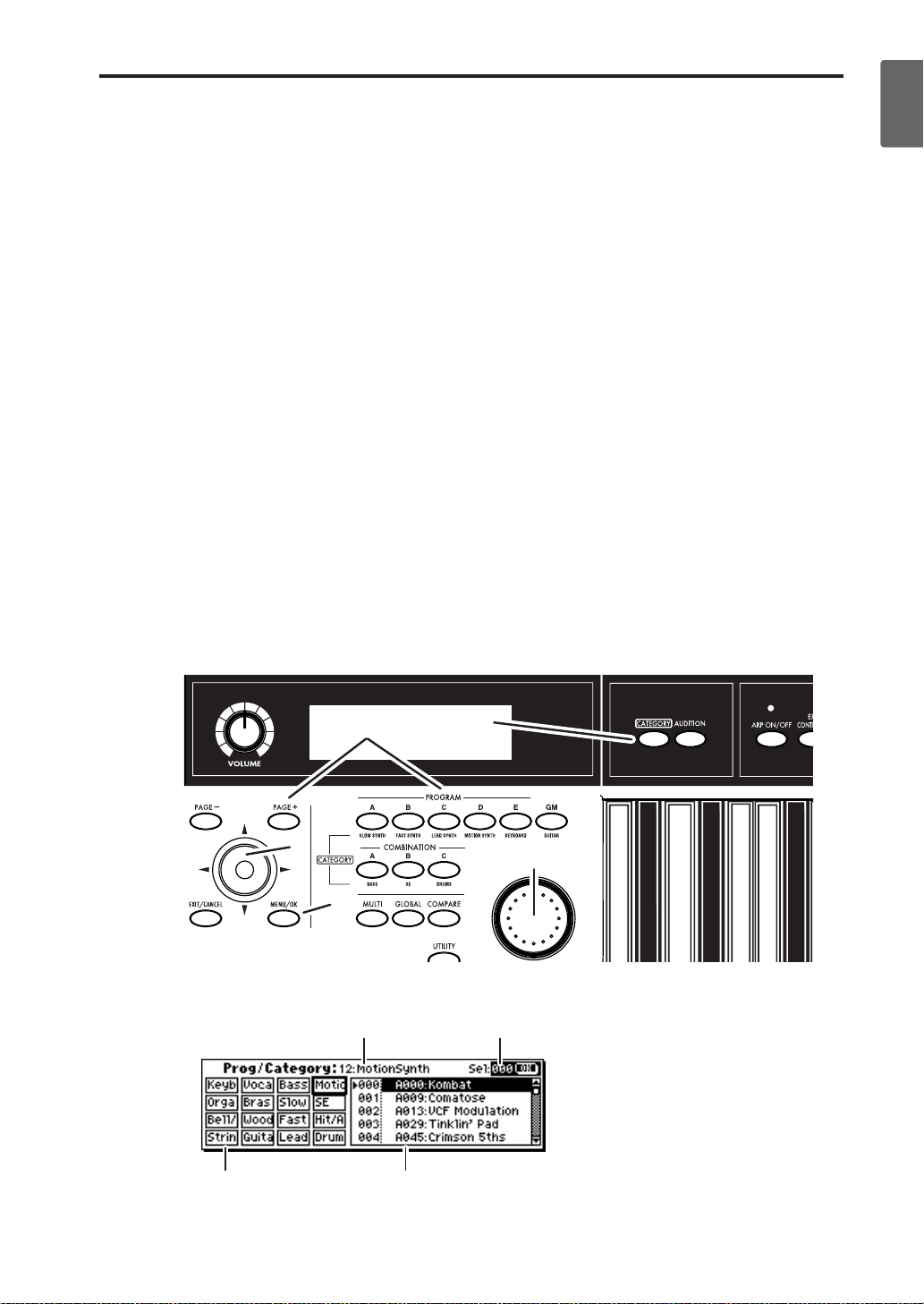
Press one of the PROGRAM [A]–[GM] buttons. (The button will light.)
You will enter Program mode, and the bank you specified will be selected. Notice that the
upper line of the display indicates “PROG 0: Play” (mode name, page number and name).
Mode name Page number and name
Category number
and name
Bank
number
Program
Select
(program
number
and name)
Tab name
Knob B assign listTab
5
3
Parameter name
Tempo
Make sure that “Program Select” (program number and name) is selected.
If this is not selected, use the ClickPoint [
π
][
†
] to highlight the “Program Select” indication.
2
Page 9
3.
4.
5.
1.
2.
Playing programs and combinations
Turn the [VALUE] dial to select the program you want to play.
You can also press the center of the ClickPoint to highlight the fi eld, then use [
a program, and press the center to finalize your selection.
Press one of the PROGRAM [A]–[GM] button to switch banks.
When you select a different Bank, that button’s LED will light, and the selected bank will
appear in the left side of the display.
For example, to select bank B, press the PROGRAM [B] button. The [B] button will light, and
the name Bank B will appear in the left of the display. The [GM] button operates differently
from the other bank buttons. Each time you press this button, the bank will switch in the
order of G
The programs are organized into banks of 128 (except for g(d)). Select the desired bank, and
then select a program number within that bank.
Play the keyboard to hear the program you selected.
While playing the keyboard, use the joystick, and realtime controllers to modify the sound.
The result will differ depending on the program, so play the keyboard while operating these
controllers to hear what they do. You can use the OCTAVE [
pitch in steps of one octave.
For more about the controllers, see “Using controllers to modify the sound” (
You can also press the [AUDITION] button (it will light) and a riff (phrase) suitable for that
program will play automatically.
→
g(d)
→
G
→
g(d) ... etc.
†
][
π
] buttons to change the
π
☞
][
†
p.5).
] to select
Using the [CATEGORY] and PROGRAM/COMBINATION buttons to select a category
The microX lets you choose programs from categories such as “synthesizer,” “bass,” or
“drums.”
Quick StartIntroductionSetupProgram
Combination
MultiEffectGlobalArpeggiatorDrum Kit
2
1
3
3
4
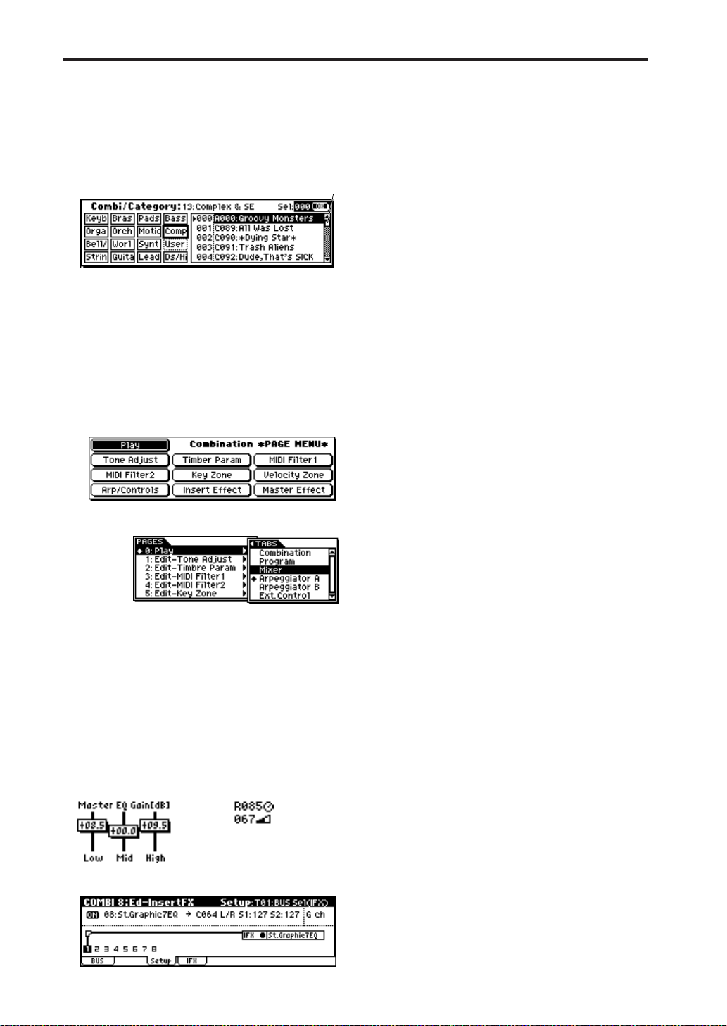
Press the [CATEGORY] button.
The category menu will appear.
Sel (Select)Category No.
Category Program
Press the PROGRAM or COMBINATION button for the desired category. The category you
specify will be selected. (A category name is printed below each bank button.)
External control
Other functions
Appendices
3
Page 10
Quick Start
3.
For example if you press the [CATEGORY] button and then press the PROGRAM [E] button,
you’ll be able to choose only from programs in the Keyboard category. The Keyboard
category contains programs such as acoustic piano, and electric piano etc.
You can also use the [PAGE+][PAGE–] buttons to step through the categories one by one.
By using the [VALUE] dial or the ClickPoint [
the programs in the same category.
Press the [MENU/OK] button to confirm your selection. If you decide not to select a
program, press the [EXIT/CANCEL] button.
π
][
†
] to select programs, you can step through
Selecting combinations by bank and number
1, 4
4.
1.
2.
3.
4.
2
5
3
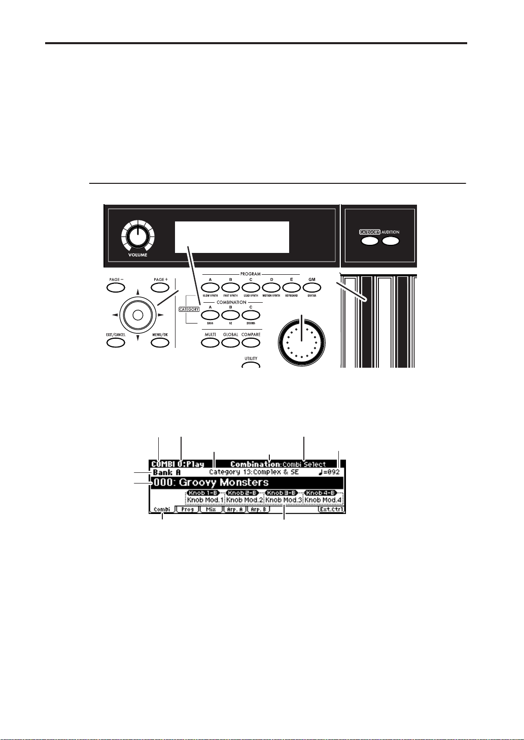
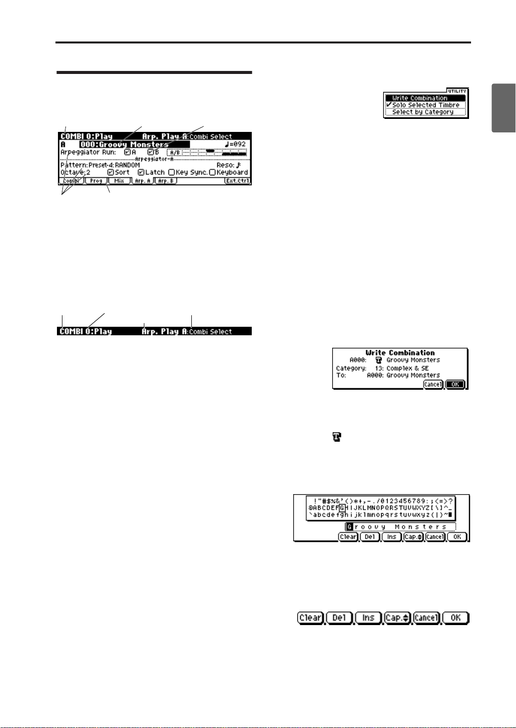
Press a COMBINATION [A]–[C] button. (The button will light.)
You will enter Combination mode, and the bank you specified will be selected. Notice that
the upper line of the display indicates “COMBI 0: Play” (mode name, page number and
name).
Mode name
Bank
number
Combi Select
(combination
number and
name)
Make sure that “Combi Select” (combination number and name) is selected.
If this is not selected, use the ClickPoint [
Turn the [VALUE] dial to select the combination you want to play.
Press a COMBINATION [A]–[C] button to switch banks.
When you select a different Bank, the button’s LED will light, and the selected bank will
appear on the left side of the display.
For example, to select bank B, press the COMBINATION [B] button. The [B] button will light,
and the name Bank B will appear in the left of the display.
Combinations are organized into banks of 128. Select the desired bank, and then select a
combination number within that bank.
Page number and name
Category number
and name
Parameter name
Tab name
Control assign listTab
π
][
†
] to highlight the “Combi Select” indication.
Tempo
4
Page 11
Playing programs and combinations
5.
Play the keyboard to hear the combination you selected.
While playing the keyboard, use the joystick, and realtime controllers to modify the sound.
The result will differ depending on the combination, so play the keyboard while operating
these controllers to hear what they do. You can use the OCTAVE [
the pitch in steps of one octave.
Note: You can’t use the [AUDITION] button to play a riff (phrase) in Combination mode.
†
][
π
] buttons to change
Selecting combinations by category
In Combination mode you can select combinations by category just as in Program mode. For the
procedure, see “Using the [CATEGORY] and PROGRAM/COMBINATION buttons to select a
☞
category” (
p.3).
Using controllers to modify the sound
You can operate the microX’s joystick, OCTAVE [
sive variation to your performances.
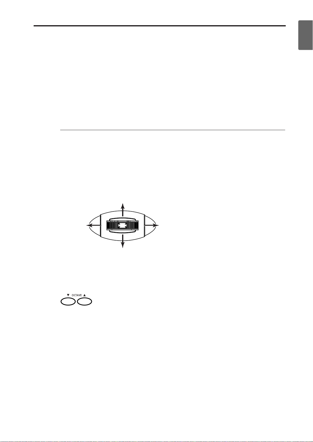
Joystick
You can use the joystick to vary the pitch or adjust the depth of modulation. The actual result
will depend on the program and combination, but these controllers are normally used to apply
the following effects.
+Y
Deepen the vibrato
†
][
π
], and realtime controllers to add expres-
Quick StartIntroductionSetupProgram
Combination
MultiEffectGlobalArpeggiatorDrum Kit
–X
Lower the
pitch
–Y
Deepen the wah effect
+X
Raise the
pitch
OCTAVE
You can use the OCTAVE [†][π] buttons to shift the pitches assigned to the keyboard in one-
octave steps over a range of 3 octaves.
External control
Other functions
Appendices
5
Page 12
Quick Start
6
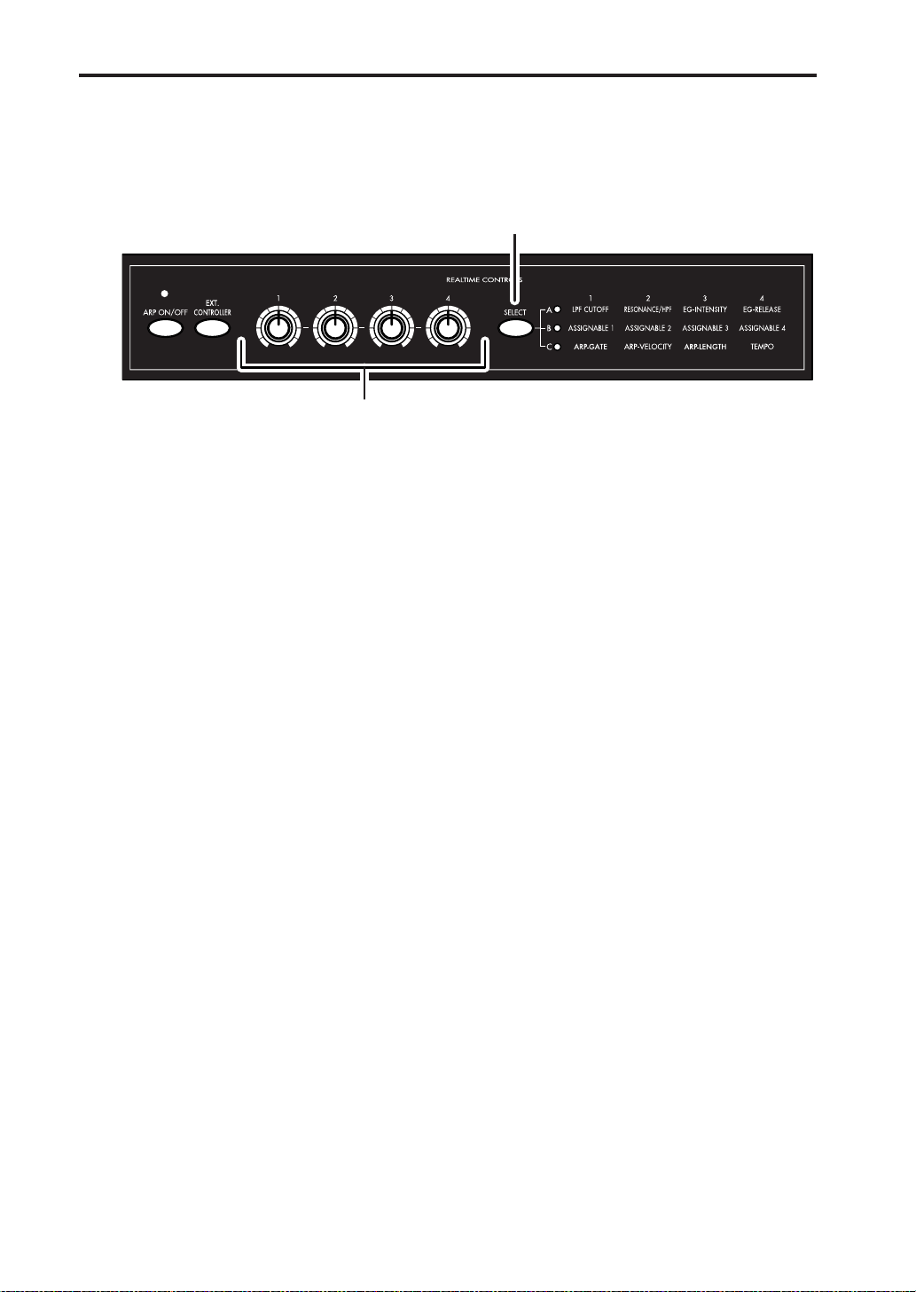
REALTIME CONTROLS [1], [2], [3], [4], [SELECT]
Use the [SELECT] button to select realtime controller mode A/B/C, and use knobs [1]–[4] to
control the tone, effects, MIDI control changes, and arpeggiator etc. while you perform. Use
these knobs when you want to modify the sound while performing, or to make simple edits.
[SELECT] button
Knobs [1]–[4]
Here we’ll explain how to use the realtime controllers in Program mode.
Note: We won’t be using the External Control function, so make sure that the [EXT.
CONTROLLER] button is dark. If it is lit, press the [EXT. CONTROLLER] button once.
1. Press one of the PROGRAM [A]–[GM] buttons. (The button will light.)
2. Choose “Program Select” (program number and name), and turn the [VALUE] dial to select
the program that you want to control using the realtime controllers.
3. Press the REALTIME CONTROLS [SELECT] button to light the “A” LED located at the right
of the button.
4. Turn knob [1] (LPF CUTOFF) to adjust the cutoff frequency of the low pass filter.
When you adjust the cutoff frequency of the filter, the brightness of the sound will change.
The effect will depend on the settings of the program parameters, but normally, rotating the
knob toward the left will darken the sound, and rotating it toward the right will brighten it.
5. Turn knob [2] (RESONANCE/HPF) to adjust the resonance level of a low pass filter or the
cutoff frequency of a high pass filter. The content that is controlled will depend on the filter
type specified by the program. By adjusting the filter resonance level, you can increase or
decrease the resonance level to add a unique character to the sound.
Adjusting the cutoff frequency of the high-pass filter will modify the thickness of the sound
from which the low frequency range has been filtered out.
6. Turn knob [3] (EG-INTENSITY) to adjust filter EG intensity (the depth at which the filter EG
is applied).
Rotating the knob will affect the depth of the filter EG. Normally, rotating the knob toward
the left will make the filter EG apply less deeply, and rotating it toward the right will make
the filter EG apply more deeply. Since the filter EG will operate based on the cutoff frequency
of the filter , knobs [1] and [3] will work together to control the tonal changes produced by the
filter.
7. Turn knob [4] (EG-RELEASE) to adjust EG release times of the filter and amp. This will
determine the time from note-off until the sound disappears.
When you adjust the knob, the release times of the filter EG and the amp EG will change.
Normally, rotating the knob toward the left will shorten the release time, and rotating it
toward the right will lengthen the release time.
8. Press the REALTIME CONTROLS [SELECT] button to light the “B” LED located at the right
of the button.
In B-mode, effective functions for each of the preloaded programs and combinations are
assigned to the knobs. This lets you use the knobs to control volume, portamento time, pan,
filter and amp EG, pitch LFO, master effect send levels, and other parameters.
Turn each knob to hear the result.
Note: The B-mode functions for the REALTIME CONTROLS [1], [2], [3], and [4] knobs can be
viewed for Program mode in the 0: Play, Program page, and for Combination mode in the 0:
Play, Combination page.
Page 13
Playing programs and combinations
Using the arpeggiator
As you selected and listened to various programs and combinations, you probably noticed that
some of them began playing automatically. This is because of the arpeggiator.
The arpeggiator is a function that automatically generates arpeggios (the notes of a chord
played individually in a rhythmic pattern). Most arpeggiators produce an arpeggio when you
play a chord on the keyboard. In addition to this, the microX’s arpeggiator is a polyphonic
arpeggiator that is able to produce a variety of chordal transformations or phrases based on the
pitch or timing of the notes you play on the keyboard. These functions let you use the arpeggiator to play a wide range of patterns including drum or bass phrases, and guitar or keyboard
backing riffs. It is also effective to use the arpeggiator as part of the sound-creating process
when creating subtly-moving pads, synth-sounds, or sound effects.
In Program mode you can use one arpeggiator.
In Combination mode and Multi mode you can use two arpeggio patterns simultaneously (dual
polyphonic arpeggiator). This gives you a variety of possibilities, such as applying separate
arpeggio patterns to a drum program and a bass program, or using splits or velocity to switch
between arpeggio patterns.
Here we’ll explain how to use the arpeggiator in Program mode.
Using the realtime controllers to control the arpeggiator
1. Press one of the PROGRAM [A]–[GM] button. (The button will light.)
2. Choose “Program Select” (program number and name), and turn the [VALUE] dial. You will
notice that the [ARP ON/OFF] button is lit for some pr ograms. Select one of these programs,
and play the keyboard; the arpeggiator will start playing.
Even for other programs, you can press the [ARP ON/OFF] button (the button will light) to
turn on the arpeggiator. Play the keyboard to make the arpeggio start.
3. Press the REALTIME CONTROLS [SELECT] button to light the “C” LED located at the right
of the button.
4. Turn the [4] (TEMPO) knob to change the tempo.
5. Turn the [1] (ARP-GATE) knob to change the duration of the arpeggiated notes.
Note: When knobs [1]–[3] are at their center position (12 o’clock), the parameters they control
will have the values specified within the program.
6. Turn the [2] (ARP-VELOCITY) knob to change the level of the arpeggiated notes.
7. Turn the [3] (ARP-LENGTH) knob to change the length of the arpeggio pattern.
Changing the length of the arpeggio pattern will change the character of the pattern. This
doesn’t work for the preset patterns (UP, DOWN, ALT1, ALT2, and RANDOM).
Quick StartIntroductionSetupProgram
Combination
MultiEffectGlobalArpeggiatorDrum Kit
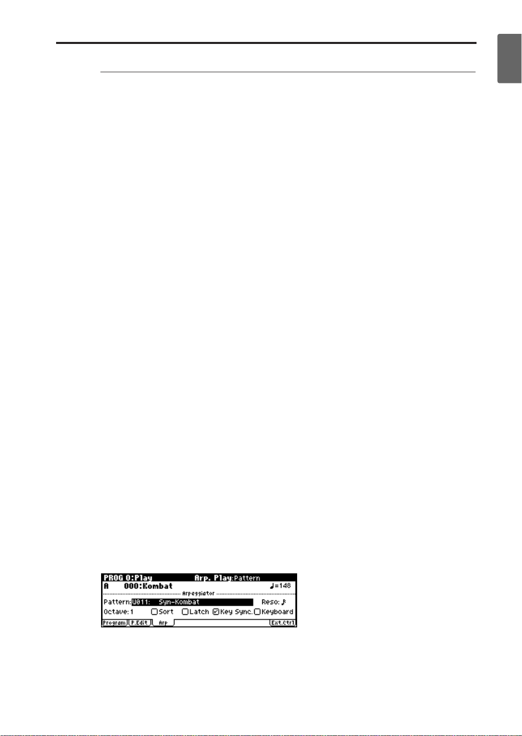
Changing the arpeggio pattern
The microX contains preset arpeggio patterns Preset-0 through Preset-4, and user arpeggio patterns U000–250.
1. Press the [PAGE+] button to access the PROG 0: Play, Arp. Play page.
2. Use the ClickPoint [√][®][π][†] to choose “Pattern,” and use the [VALUE] dial to select an
arpeggio pattern.
3. Play the keyboard and try out various arpeggio patterns.
External control
Other functions
Appendices
7
Page 14
Quick Start
Listening to the demo songs
The microX contains demonstration songs.
Take a moment to listen to these demo songs to experience the diverse sounds and rich expressive potential of the microX.
12, 3
4.1
4.2
5
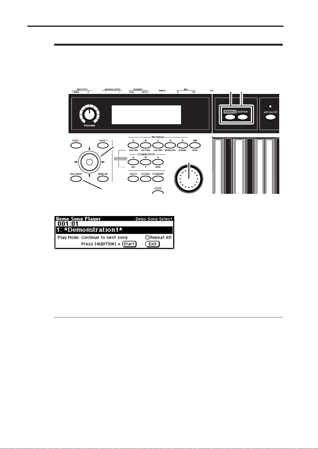
1. Hold down the [CATEGORY] button and press the [AUDITION] button.
The Demo Song Player page will appear.
2. Press the [AUDITION] button to begin playback.
3. Press the [AUDITION] button once again to stop playback.
4. To select a song for playback, use the ClickPoint [π][†] to select the song name (“Demo
Song Select”) and use the [VALUE] dial to change songs.
5. To exit the Demo Song Player page, press the [EXIT/CANCEL] button.
You can also exit by pressing one of the PROGRAM [A]–[GM], COMBINATION [A]–[C],
[GLOBAL], or [MULTI] buttons.
Changing the play mode
• You can play back the demo songs in succession or only one song at a time; use the Click-
Point [√][®][π][†] to select “Play Mode” and use the [VALUE] dial etc. to change the set-
ting.
Continue to next song: When the currently selected demo song finishes playing, the next
demo song will play automatically.
Stop at end of selected song: When the currently selected demo song finishes playing,
playback will stop.
• If you want all of the demo songs to continue playing repeatedly, use the ClickPoint
[√][®][π][†] to select the “Repeat All” check box and then press the ClickPoint center to
add a check mark.
Note: This is available only if “Play Mode” is set to Continue to next song.
This Quick Start section is just an introduction to intr oduce you to your new synthesizer. Please
take the time to read the more in-depth sections of this manual that follow.
8
Page 15

Main features
Introduction
Quick StartIntroductionSetupProgram
High-quality sound featuring the HI
synthesis system
The microX Music Synthesizer features Korg’s
acclaimed HI (Hyper Integrated) synthesis system.
The HI (Hyper Integrated) synthesis system is a
PCM tone generator system with extensive modulation and effect routing capabilities, as well as full
digital signal processing that guarantees a rich,
pristine sound.
Tone generator section:
• 64 MB of preset PCM ROM containing 642 multisamples and 929 drumsamples.
• The sampling frequency is 48 kHz, and the
maximum polyphony is 62 voices.
Filter/synthesis section:
• 24 dB/oct Low Pass Resonance type or 12 dB/
oct Low Pass & High Pass type filters can be
used. A wide variety of filter effects can be
achieved, from active sounds with aggressive
resonance to subtle tones using a high pass filter.
•A broad range of editing parameters gives you
control over every aspect of the sound.
Effect section:
• One insert effect (stereo-in/stereo-out), two
master effects (mono-in/stereo-out), and a
three-band master EQ (stereo-in/stereo-out)
can all be used simultaneously. You can select
from 89 types of effect algorithms, and edit
them.
• Highly flexible effect routing is possible. Effects
can also be routed freely to the individual outputs.
Alternate Modulation and Effect Dynamic
Modulation:
• The synthesis section (filter etc.) provides Alternate Modulation functionality, and the effect
section provides Effect Dynamic Modulation
functionality. This allows you to freely apply
modulation to parameters that affect the pitch,
filter, amp, EG, LFO, effects etc.
• LFO and delay time parameters can be synchronized to MIDI clock/tempo. You can synchronize sounds or effects to the tempo of the
sequencer or the arpeggiator.
A great selection of 640 programs
In the Program mode, the microX provides 640
user programs, plus 128 programs + 9 drum sets
for GM compatibility.
When shipped from the factory, it is loaded with
high-quality programs that cover a wide range of
musical needs.
Programs using multisamples that provide a broad range of sounds
Based on 642 different multisamples that deliver a
broad range of sounds ranging from acoustic
instruments such as piano, guitar, and trumpet, to
synthesizer sounds or sound effects (oscillator),
the preset programs provide a rich variety of editable parameters (filter and amp), effects, and
arpeggiators.
Drum programs that support any style
of rhythm part
Based on 40 user drum kits and nine GM2-compatible ROM drum kits, and taking full advantage
of numerous editable parameters, effects, and
arpeggiators, the microX provides a gr eat selection
of preset programs for any style of music.
The drum kits that are the basis of each drum program allow you to freely map any of the 929 drum
or percussion sounds to each note of the keyboard.
You can also create your own drum kits, and even
specify filter and amp settings, effect settings, and
individual audio output routings for each separate
key.
384 different combinations let you
freely combine programs
The microX provides 384 user combinations. The
factory settings contain a wide variety of Preloaded combinations.
Combination
MultiEffectGlobalArpeggiatorDrum Kit
External control
Other functions
Appendices
9
Page 16

Introduction
A combination allows you to use layers, splits, or
velocity switching etc. to combine up to eight programs together with the effects and the two arpeggiators, in order to create complex sounds that
could not be produced by a program. You can also
create combis that include external tone generators.
Effects that can creatively manipulate the sound or generate subtle
ambience
The microX’s effects can be used in many ways,
ranging from manipulating the sound dramatically to creating spacious reverberation. (☞p.9
“High-quality sound featuring the HI synthesis
system”)
4 channel audio outputs
In addition to the (MAIN OUTPUT) L/MONO
and R main stereo audio outputs, microX pr ovides
two individual audio outputs, for a total of four
channels of audio output. The sound from each
oscillator, drum, timbre/track, or insert effect can
be routed freely to any output.
Multi mode plays multiple tracks of
data from an external sequencer
In Multi mode, the microX can operate as a 16track MIDI multi-timbral sound module, receiving
multiple tracks of performance data from an external sequencer or similar device. Since you can use
the effects and the two arpeggiators as well, the
microX will also function as a more advanced
sound module.
You can create, save and recall numerous Multi
sets in the microX and it also supports GM (General MIDI System Level 1), making it easy to use as
a sound module for a desktop music system.
is also effective for use with subtly moving pads,
synth sounds, or sound effects.
In Combination mode, and Multi mode, the
microX provides dual polyphonic arpeggiators
that can simultaneously play two arpeggio patterns. You can apply separate arpeggio patterns to
drum and bass programs, or use keyboard splits
or velocity to switch between arpeggio patterns
for an even more dynamic performance.
External control setups
You can assign twelve MIDI control changes to the
REALTIME CONTROLS [1]–[4] knobs. The
microX can hold 64 such sets of twelve control
change assignments. You can use this capability to
control a wide range of parameters in realtime,
such as on the KORG Legacy Collection or other
soft synthesizers, or the level and pan of your
DAW (Digital Audio Workstation).
Direct USB connection to your computer
The microX provides a convenient USB connector
that allows single-cable connection to your computer, without requiring a MIDI interface or MIDI
connectors. The microX supports Windows XP
and Macintosh OS X 10.3 or later.
microX Plug-In Editor supports editing from within your DAW software
The “microX Editor” is a stand-alone program that
lets you edit the microX from your Macintosh or
Windows computer.
On the other hand, the “microX Plug-In Editor”
lets you edit the microX as a plug-in instrument
from within a host application such as DAW (Digital Audio Workstation) software. It supports VST ,
Audio Units, and RTAS formats. Both editors are
included with your microX.
Dual polyphonic arpeggiator
Five preset arpeggio patterns (UP, DOWN, ALT1
ALT2, RANDOM) and 251 user arpeggio patterns
are provided. With the factory settings, these contain a wide variety of preload arpeggio patterns.
In addition to providing conventional arpeggiator
functions, the polyphonic arpeggiator of the
microX can respond to the pitches or timing of
your keyboard playing, and produce a diverse
range of chords or phrases. This can be used to
play a variety of drum phrases, bass phrases, or
guitar and keyboard backing riffs. The arpeggiator
10
Page 17
Front and rear panel
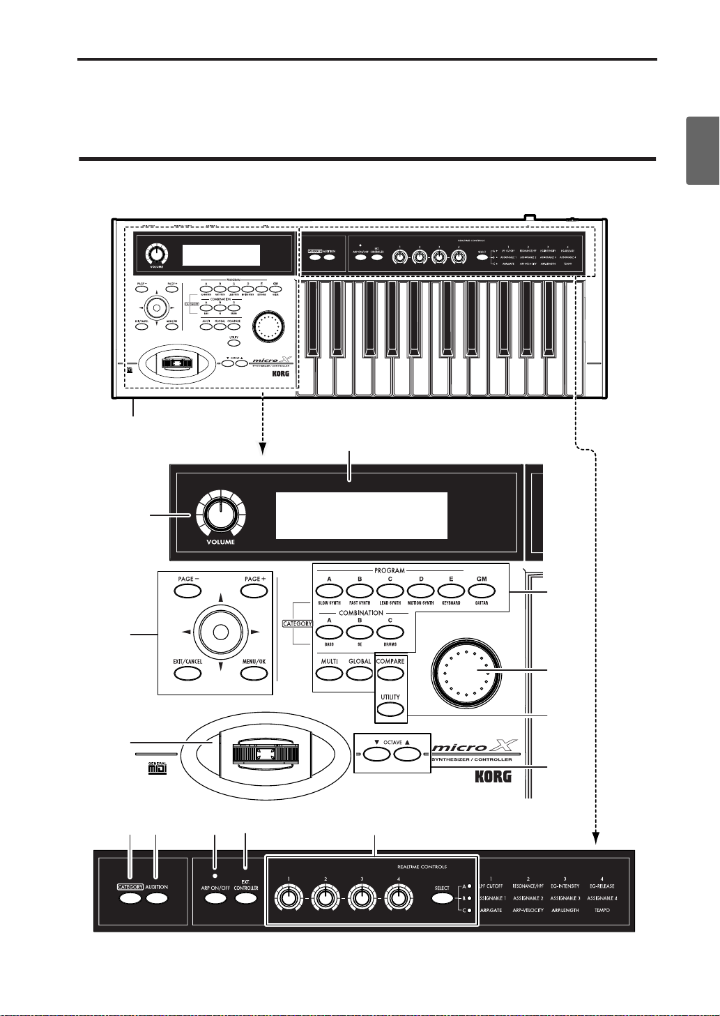
Front and rear panel
Front panel
14
Quick StartIntroductionSetupProgram
Combination
6
MultiEffectGlobalArpeggiatorDrum Kit
1
10
12
7 8 3 42
5
9
11
13
External control
Other functions
11
Appendices
Page 18

Introduction
1. [VOLUME] knob
This adjusts the volume of the (MAIN OUTPUT)
L/MONO, R jacks, as well as the volume of the
headphone jack.
2. REALTIME CONTROLS
[SELECT] button
[1]–[4] knob
Use the [SELECT] button to choose one of the realtime controller modes - A/B/C - and use knobs
[1]–[4] to control the tone, effects, MIDI control
changes, and arpeggiator etc. while you perform.
(☞p.43, 92)
When you turn the [EXT. CONTROLLER] button
on (lit), External Control will be on, and the REALTIME CONTROLS [1]–[4] knobs will transmit
MIDI messages to external MIDI devices. (☞p.111)
3. Arpeggiator
The microX’s arpeggiator is a polyphonic arpeggiator.
[ARP ON/OFF] button
This button turns the arpeggiator on/off. When
on, the button will light. (☞p.91)
The LED located above the [ARP ON/OFF] button
blinks at quarter-note intervals of the tempo.
In REALTIME CONTROLS C-mode, you can use
the [1], [2], [3], and [4] knobs to vary the arpeggio
pattern in realtime.
4. External
You can use the REALTIME CONTROLS [1], [2],
[3], and [4] knobs to transmit MIDI messages.
[EXT. CONTROLLER] button
This switches the external function on/off. When
on, the button will light. (☞p.111)
When this is on, you can use the [SELECT] button
to select the MIDI messages assigned to the knobs,
and operate the REALTIME CONTROLS [1], [2],
[3], and [4] knobs to transmit these MIDI messages
to an external MIDI device.
5. MODE/BANK Select
Use these buttons to select banks and enter modes.
The microX has four modes. (☞p.19)
PROGRAM [A], [B], [C], [D], [E], [GM] button
COMBINATION [A], [B], [C] button
[GLOBAL] button
[MULTI] button
6. Display
You can select a page, tab, or parameter in the display, and specify its value. (☞p.15)
7. CATEGORY
You can select programs, multisamples, combinations, timbre/track programs, effects, or drum
samples by category.
[CATEGORY] button
Press this button to access the category menu, and
choose a program etc. from the list. The category
menu will appear if you have selected an appropriate mode, page, or parameter. (☞p.38, 45, 82,
108)
8. AUDITION, Demo Song Player
[AUDITION] button
In Program mode when you press the [AUDITION] button (the button will light), a riff (phrase)
appropriate for the preloaded or preset program
will play. (This is called the Audition function.) To
stop auditioning, press the [AUDITION] button
once again.
Demo song player
When you hold down the [CATEGORY] button
and press the [AUDITION] button, the Demo
Song Player page will appear.
Select a song and press the [AUDITION] button to
begin playback. Press the [AUDITION] button
once again to stop playback.
To exit from this mode, press the [EXIT/CANCEL]
button. (☞p.8)
12
9. VALUE controller
The [VALUE] dial is used to set the value of the
selected parameter. (☞p.20)
[VALUE] dial
Page 19

Front panel
10. PAGE, CURSOR
[PAGE+][PAGE–] buttons
You can use these buttons to move forward or
backward through the different tabs in a page.
By holding down the [MENU/OK] button and
pressing these same buttons you can move forward or backward through the pages themselves,
such as page 0, 1, 2, etc. (☞p.20)
While the category menu is displayed, you can use
these buttons to step through the categories one
by one. (☞p.38)
ClickPoint
The ClickPoint is a multi-function controller.
You can move the ClickPoint in the
([√][®][π][†]) direction to select parameters. In
addition, you can press directly down on the center of the ClickPoint (in toward the body of the
instrument) to select an item in the display.
After selecting a parameter expressed as a numerical value etc., press the center of the ClickPoint;
the value will be highlighted, and now you can
use [π][†] to increase or decrease the value. To
finalize the value, press the center once again.
If you press the [EXIT/CANCEL] button while
pressing the ClickPoint center, the selected value
will be reset to 0 or the minimum value.
You can also press the ClickPoint center to access a
dialog box, to set the numerical value of an editable condition, or to turn a switch on/off. If you
press the ClickPoint on the utility menu, page
menu, or a text edit button (☞p.15), the selected
command or page will appear. Pressing the ClickPoint center on a check box will switch the item
on/off. Pressing the ClickPoint center on a button
such as OK or CANCEL will confirm the corresponding choice.
[MENU/OK] button
Press this button to access the page menu. (☞p.19)
By holding down the [MENU/OK] button and
pressing the [PAGE+] button or [PAGE–] button,
you can move forward or backward in steps of one
page.
If a dialog box is open, this button will confirm the
settings in the dialog box and close it. (This is the
same function as the OK button.)
[EXIT/CANCEL] button
When you are in a page other than 0 of each mode,
you can press this button to move to page 0 of that
mode.
If you press the [EXIT/CANCEL] button while
pressing the ClickPoint center, the selected value
will be reset to 0 or the minimum value.
When a dialog box is open, this button will cancel
the settings made in the dialog box and close the
dialog box (corresponds to the “Cancel”). If a Utility menu or page menu is open, pressing [EXIT/
CANCEL] button will close the menu.
11. UTILITY, COMPARE
[UTILITY] button
Press this button when you want to use the utility
functions. (☞p.21)
[COMPARE] button
Use this button when you wish to compare the
sound of the program, combination or multi set
that you are currently editing with the un-edited
sound that was written into memory. (☞p.20)
12. JOYSTICK
This controls pitch or modulation, etc.
Move the joystick up/down or left/right (+Y, –Y,
–X, +X) to control (☞p.40).
Various program parameters and effect parame-
ters will determine what is controlled by the joystick.
13. OCTAVE
OCTAVE [†][π] buttons
These buttons change the pitch range assigned to
the keyboard over a ±3 octave range in one-octave
steps. (☞p.41)
14. Headphone jack
This 1/8" mini-stereo phone jack carries the same
signal as the (MAIN OUTPUT) L/MONO, R jacks.
The headphone volume is controlled by the [VOLUME] knob.
Quick StartIntroductionSetupProgram
Combination
MultiEffectGlobalArpeggiatorDrum Kit
External control
13
Other functions
Appendices
Page 20
Introduction
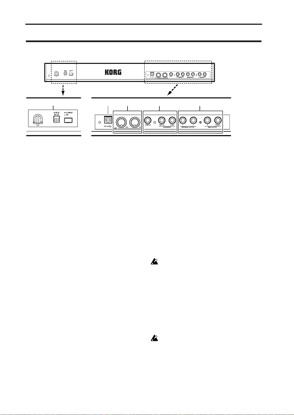
Rear panel
5
3 2 14
1. AUDIO OUTPUT
Connect these outputs to the input jacks of your
amp or mixer . In addition to the (MAIN OUTPUT)
L/MONO and R main stereo audio outputs, the
microX provides two individual audio outputs.
(☞p.25)
MAIN OUTPUT L/MONO, R jack
INDIVIDUAL OUTPUT 1, 2 jack
2. PEDALS
You can connect a damper pedal, foot switch, and
foot pedal to these jacks. This gives you a broader
range of functions and effects to control. (☞p.26)
ASSIGNABLE PEDAL jack
ASSIGNABLE SWITCH jack
DAMPER jack
3. MIDI
MIDI lets you connect microX to computers or
other MIDI devices, for sending and receiving
notes, controller gestures, sound settings, and so
on. (☞p.35)
MIDI IN connector
MIDI OUT connector
4. USB
USB connector
(for connecting to computer)
You can connect your computer to this connector.
Using a single USB cable, your microX can send
and receive MIDI information directly to and fr om
a computer, without requiring a MIDI interface.
(☞p.32)
What is USB?
USB stands for Universal Serial Bus, and is an
interface for transferring data between a computer, a keyboard and/or peripheral devices.
Note: The USB connector of the microX is only able
to transmit and receive MIDI data.
5. Power supply
Be sure to see “T urning the power on/of f” (☞p.23)
and follow the correct procedure described there.
Power switch
This switch turns the power on/off.
AC adapter connector
Connect this to the included AC adapter.
Connections must be made with the power
turned off. Please be aware that careless
operation may damage your speaker system
or cause malfunctions.
Cable hook
Use this to secure the cable of the included AC
adapter. After connecting the AC adapter, fasten
the cable around the hook located on the microX’s
rear panel so that the cable will not be pulled out
inadvertently. Leave enough slack on the plug end
so that you can disconnect it if you want to.
Be careful not to bend the base of the plug any
more than necessary.
14
Page 21
Objects in the Display and their functions
Objects in the Display and
their functions
a: Current page d: Edit cell e: Check box
c: Parameters
a: Current page
This indicates the current page within the selected
mode.
From the left, this area shows the mode name,
page number: name, tab name, and the parameter
name of the edit cell.
Mode name
b: T ab
Page number:name
Tab name
Parameter name
* Utility menu
When you press the [UTILITY] button in a page,
the utility menu will appear. The utility menu contains commands that can be used in that page. The
utility menu that appears will differ depending on
the page that is selected.
For details on selecting and executing a utility
command, see “4. Selecting and executing a Utility
function” (☞p.21).
* Dialog boxes
When you select a utility menu command etc., a
dialog box will open.
Use the ClickPoint [√][®][π][†] to select parameters. T o enter a parameter value, use the [VALUE]
dial, the ClickPoint [π][†].To execute the utility
command, press the [MENU/OK] button.
If you decide not to execute, press the [EXIT/
CANCEL] button. The [EXIT/CANCEL] button is
equivalent to “Cancel,” “Done,” or “Exit.”
Quick StartIntroductionSetupProgram
Combination
MultiEffectGlobalArpeggiatorDrum Kit
b: Tab
Most pages are divided into two or more tabs.
Use the [PAGE+][PAGE–] buttons to select a tab
and view that page.
c: Parameters
The parameters for various settings are displayed
in the display. Use the ClickPoint [√][®][π][†]
to select the desired parameter.
d: Edit cell
When you use the ClickPoint [√][®][π][†], the
selected parameter will be highlighted in the display. This area is called the edit cell, and your
editing will affect the highlighted area. For details
on how to edit the value, see “3. Selecting a
parameter and editing the value” (☞p.20).
e: Check box
Use the ClickPoint [√][®][π][†] to select a
check box, and use the [VALUE] dial, the center of
the ClickPoint to add or remove the check mark.
When checked, the parameter will function, when
unchecked, the parameter will not function.
* Text dialog box
Use the ClickPoint [√][®][π][†] to select a text
button such as , and press the center to open the
text dialog box.
In this dialog box you can rename text (e.g., the
name of a program, combination, or multi set).
(☞p.114)
* Function buttons
Use the ClickPoint [√][®][π][†] to select one of
these buttons and press the center to execute the
following functions.
External control
Other functions
15
Appendices
Page 22
Introduction
Slid
Knob
* Scroll bar
This indicates that the list contains more selections
or parameters than can be shown in the screen at
one time. Use the ClickPoint [π][†] to move
within the list.
Scroll bar
* Page menu
In Combination, Program, Global, or Multi modes,
pressing the [MENU/OK] button will display a
list of the pages in that mode.
To select a page, use the ClickPoint [√][®][π][†]
to select the desired page and press the center.
(☞p.19 “Using the page menu to move”)
When “Page Menu Style” = Icon
When “Page Menu Style” = List
Note: You can set “Page Menu Style” in the
GLOBAL 0: System, Preference page.
* Other objects
To use slider- or knob-shaped objects, use the
ClickPoint [√][®][π][†] to select the desired
item, and use the VALUE controllers to adjust the
value.
Other types of objects are shown in the effect routing screen.
er
Routing
16
Page 23

Basic Information
Basic Information
About the microX’ modes
The microX has a wide range of capabilities; it lets
you play programs/combinations, edit them, play
the microX’s sound generator using musical performance data from an external MIDI sequencer,
and make settings that affect the entire microX,
such as transposition and tuning. The largest unit
used to organize these features is called a mode.
The microX has four modes.
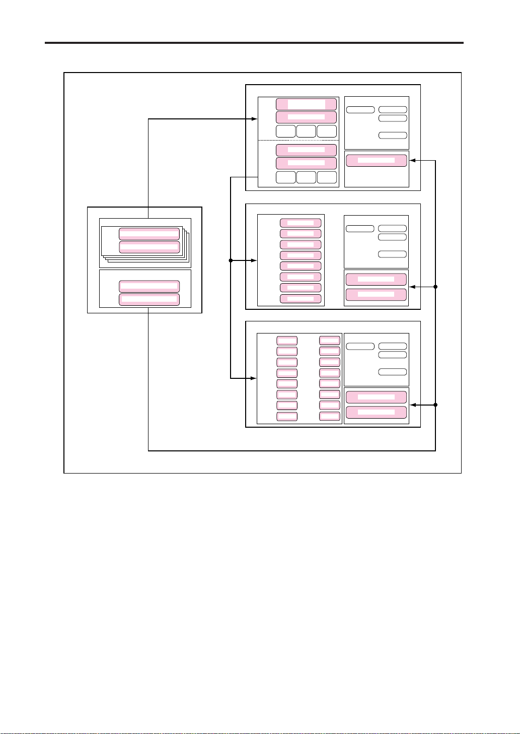
Program mode
Programs are the basic sounds of microX. In Program mode, you can:
• Select and play Programs
• Edit Programs
Make detailed settings for oscillators, filters,
amps, EGs, LFOs, effects, arpeggiator, etc.
•Create drum programs using drum kits (as created in Global mode)
• Play and control one Arpeggiator (☞p.43)
You can use the Tone Adjust function to make
simple edits for the program of a track.
Assign Programs to each of the 16 MIDI Tracks,
each with separate volume, pan, EQ, and
keyboard and velocity zones; make settings for
effects, and two Arpeggiator (☞p.69)
Global mode
Global mode lets you make overall settings for the
entire microX, and edit arpeggiators, drum kits
and external control sets. For instance, you can:
• Make settings that affect the entire microX,
such as master tune and global MIDI channel
•Create user drum kits, arpeggiators, user scales
and external control sets
• Rename program, and combination categories
• Set the function of the assignable pedals and
assignable switches
• Make settings for the external control function.
(☞p.111)
•Transmit MIDI System Exclusive data dumps
Quick StartIntroductionSetupProgram
Combination
MultiEffectGlobalArpeggiatorDrum Kit
Combination mode
Combinations are sets of up to 8 Programs that
can be played simultaneously, letting you create
sounds more complex than a single Program. In
Combination mode, you can:
• Select and play Combinations
• Use microX as a 8-track multitimbral tone generator
• Edit Combinations
You can use the Tone Adjust function to make
simple edits for the program of a timbre.
Assign Programs to each of the 8 Timbres, each
with separate volume, pan, EQ, and keyboard
and velocity zones; make settings for effects,
and Arpeggiator . (☞p.60)
• Control and play up to two Arpeggiator
Multi mode
You can use the microX as a 16-track multi-timbral
sound generator.
The microX will receive GM or other performance
data from an external MIDI sequencer, and play
back this data.
• Select and playback Multi sets
• Edit Multi sets
External control
Other functions
Appendices
17
Page 24
Introduction
PROGRAM MODE
OSC 1
Multi Sample - H
Drum Kit
Multi Sample - L
FILTER1 AMP1
PITCH1
OSC 2
Multi Sample - H
Multi Sample - L
FILTER2
PITCH2
AMP2
Insert / Master Effect
IFX
Arpeggiator
MFX 1
MFX 2
MEQ
GLOBAL MODE
DRUM KIT
Key
Drum Sample / Sample - H
Assign
Drum Sample / Sample - L
ARPEGGIATOR PATTERN
User Pattern: Preset-0 - 4
User Pattern: U000 - 250
COMBINATION MODE
TIMBRE 1
PROGRAM
TIMBRE 2
PROGRAM
TIMBRE 3
PROGRAM
TIMBRE 4
PROGRAM
TIMBRE 5
PROGRAM
TIMBRE 6
PROGRAM
TIMBRE 7
PROGRAM
TIMBRE 8
PROGRAM
MULTI MODE
TRACK 9
TRACK 10
TRACK 11
TRACK 12
TRACK 13
TRACK 14
TRACK 15
TRACK 16
PROGRAM
PROGRAM
PROGRAM
PROGRAM
PROGRAM
PROGRAM
PROGRAM
PROGRAM
TRACK 1
TRACK 2
TRACK 3
TRACK 4
TRACK 5
TRACK 6
TRACK 7
TRACK 8
PROGRAM
PROGRAM
PROGRAM
PROGRAM
PROGRAM
PROGRAM
PROGRAM
PROGRAM
Insert /Master Effect
Insert /Master Effect
IFX
Arpeggiator - A
Arpeggiatpr - B
IFX
Arpeggiator - A
Arpeggiatpr - B
MFX 1
MFX 2
MEQ
MFX 1
MFX 2
MEQ
18
Page 25

Basic operations
After you’ve powered-on the microX, here’s how
to perform basic operations such as selecting
modes and pages.
1. Selecting modes
• In order to use a particular function on the
microX, you must first select the appropriate
mode.
Press one of the front panel mode buttons to
enter the corresponding mode.
PROGRAM [A]–[GM] button: Program mode
COMBINATION [A]–[C] button:
Combination mode
[MULTI] button: Multi mode
[GLOBAL] button: Global mode
• When you press one of the PROGRAM [A]–
[GM] buttons or COMBINATION [A]–[C] buttons, you will enter the selected mode, and the
corresponding bank will also be selected as
well as a program or combination within that
bank.
For example if you’re editing a program in
Program mode, and you press a different
PROGRAM [A]–[GM] button, the program
will change and the settings you had been
editing will disappear. The same is true for
Combination mode, and the settings you had
been editing will disappear if you press a
different COMBINATION [A]–[C] button.
• For the [GLOBAL] button or [MULTI] button,
pressing that button once again will take you
back to the mode and page in which you had
previously been.
Note: For example, suppose you’re editing a
program in Program mode, and you press the
[GLOBAL] button to enter Global mode. When
you’ve finished editing the Global settings and
are ready to resume editing the program, press
the [GLOBAL] button once again to return to
Program mode. If you return to Pr ogram mode
by pressing the PROGRAM [A]–[GM] of any
bank other than the bank in which you were
editing, the settings you had been editing will
disappear. For this reason, we recommend that
you return to Program mode by pressing the
[GLOBAL] button once again, rather than by
pressing a PROGRAM [A]–[GM] button. The
same is true for the [MULTI] button.
Basic operations
2. Selecting pages
Each mode has a large number of parameters,
which are grouped into pages. These are further
subdivided by tabs into up to eight tab pages.
• Make sure that the desired mode is selected.
For details on selecting a mode, see “1.
Selecting modes,” above.
In this explanation we’ll use Combination
mode as an example.
Press the COMBINATION [A]–[C] buttons.
Note: The COMBI 0: Play page will appear. (This is
shown in the upper left of the display.)
In Combination, Program, or Multi modes (i.e., in
other than Global mode), you will normally
perform in this 0: Play page. You can also make
simple adjustments (edits) to the sound while
you’re in this page. To make more detailed
adjustments, use page 1 (COMBI 1: Ed–Tone
Adjust, etc.) and following.
Selecting a page
Using the page menu to move
In Combination, Program, Global, and Multi
modes, you can press the [MENU/OK] button to
view a list of the pages that make up that mode.
1. Press the [MENU/OK] button.
The page menu will appear.
The page in which you were when you pressed
the [MENU/OK] button will be highlighted as
an indication.
Quick StartIntroductionSetupProgram
Combination
MultiEffectGlobalArpeggiatorDrum Kit
External control
Other functions
19
Appendices
Page 26
Introduction
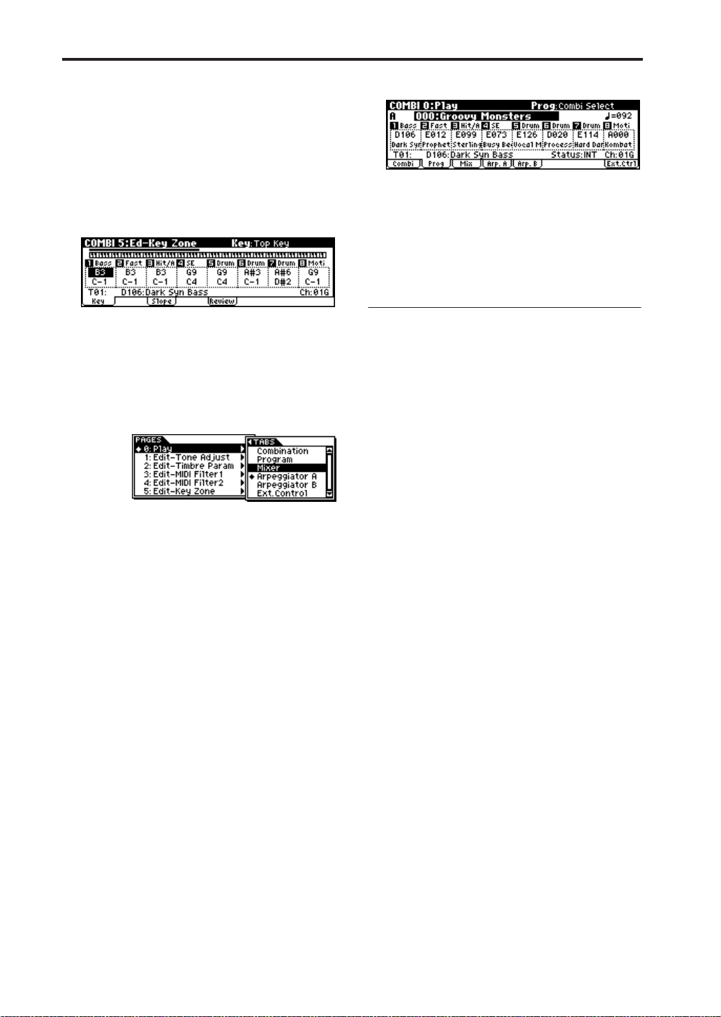
2. Use the ClickPoint [√][®][π][†] to select the
page you want to view.
3. When you’ve made your selection, press the
center of the ClickPoint.
You will jump to the selected page, and that
page will appear.
As an example here, try selecting “Key Zone.”
The 5: Ed–Key Zone page will appear.
2. As you repeatedly press the [PAGE+] button or
[PAGE–] button, you will move consecutively
through the tabs. As you page up past the last
tab of a page, you will then move to the first tab
of the next page. Likewise, as you page down
past the first tab of a page, you will then move
to the last tab of the preceding page.
Note: The page that appears will be the page of the
tab you selected most recently.
Note: If you set the Global mode setting “Page
Menu Style” to List, you can move by selecting
pages and tabs as shown in the following
illustration. (The display shown in step 2 is for
when “Page Menu Style” = Icon.)
Using the [MENU/OK] button +
[PAGE+][PAGE–] buttons to move
• Hold down the [MENU/OK] button and press
the [PAGE+] ([PAGE–] button.
In Combination mode, you will move between
pages in the order of 0: Play ↔ 1: Ed–Tone Adjust
↔ 2: Ed–Track Parameter ↔ 3: Ed–MIDI Filter1 ↔
... etc. The page that appears will be the page of
the tab you selected most recently.
[EXIT/CANCEL] button
•You can press the [EXIT/CANCEL] button to
return to page 0 from any page.
Selecting tabs
[PAGE+][PAGE–] buttons
You can press these buttons to move forward or
backward in steps of one tab.
1. Press the [PAGE+] button to access the page for
the next (right) tab. (Press [PAGE–] button to
access the page for the previous (left) tab.)
This example shows the Combination page
through Prog page of COMBI 0: Play.
3. Selecting a parameter and editing
the value
1. Use the ClickPoint [√][®][π][†] to select the
parameter you want to edit.
The value will be highlighted, and the
parameter name is displayed in the upper right
of the display. (We call this the “edit cell.”)
2. To modify the value of the edit cell, use the
[VALUE] dial or the ClickPoint.
Note: You can use the [COMPARE] button to
compare the sound you’re editing with the
original unedited sound.
VALUE controllers
[VALUE] dial
Use this dial to edit the selected parameter’s value.
ClickPoint
After selecting a parameter expressed as a numerical value etc., press the center of the ClickPoint;
the value will be highlighted, and now you can
use [π][†] to increase or decrease the value. To
finalize the value, press the center once again.
If you press the [EXIT/CANCEL] button while
pressing the ClickPoint center, the selected value
will be reset to 0 or the minimum value.
In addition, you can press the ClickPoint center to
turn a check box or switch on/off.
[COMPARE] button
Use this when you wish to compare the edits you
have made to a program or combination’s sound
with the un-edited original (i.e., the sound that is
written into memory).
When editing a program or combination, press
this switch. The LED will light, and the last-written settings for that program number or combination number will be recalled. When you press the
[COMPARE] button once again, the LED will go
20
Page 27
Basic operations
dark and you will return to the settings that you
were editing.
If you edit the settings that are recalled by pressing the [COMPARE] button (i.e., the settings that
are written into memory), the LED will go dark,
and it will not be possible to return to the previous
edits by pressing the [COMPARE] button again.
The Compare function is not available in
Global mode.
4. Selecting and executing a Utility
function
The utility functions provide commands that are
specific to each page, such Write (save) or Copy.
The available utility functions will depend on the
page you select.
For example, the utility functions in Program
mode let you write (save) the settings, or let you
perform convenient editing operations such as
copying settings between oscillators or effects, or a
Sync function that lets you edit two EGs together.
1. Press the [UTILITY] button.
The utility menu will appear.
2. Use the ClickPoint [π][†] to select a
command.
3. Press the ClickPoint center.
A dialog box for the selected utility will appear.
(Alternatively, you can access the dialog box by
pressing the [UTILITY] button once again or
pressing the [MENU/OK] button.)
For check-type commands, the status of the
command will simply change without any
dialog box appearing.
4. Use the ClickPoint [√][®][π][†] to select a
parameter in the dialog box.
5. To set the parameter value, use the [VALUE]
dial, or the ClickPoint (press the center and
then use [π][†]).
6. To execute the utility command, press the
[MENU/OK] button.
If you decide not to execute, press the [EXIT/
CANCEL] button. The [EXIT/CANCEL]
button is the same as “Cancel,” “Done,” or
“Exit.”
The dialog box will close.
• If the utility menu is displayed, press the
[EXIT/CANCEL] button to close the menu.
5. Writing (saving)
When you’re finished editing, you can save your
changes if necessary.
For example if you’ve edited a program, your
changed will be lost if you select another program
or turn off the power. The same applies to a combination or multi set.
Settings you edit in Global mode will be remembered as long as the power is on, but your changes
will be lost when you turn off the power.
For details on the Write operations, see the following pages.
•Programs ☞p.45
• Combinations ☞p.61
• Multi sets ☞p.75
• Global settings (pages 0–3) ☞p.90
•Drum kits ☞p.110
• Arpeggio patterns ☞p.104
• External control ☞p.112
• Saving data ☞p.117
21
Quick StartIntroductionSetupProgram
Combination
MultiEffectGlobalArpeggiatorDrum Kit
External control
Other functions
Appendices
Page 28

Introduction
22
Page 29
Setup
Turning the power on/off
Quick StartIntroductionSetupProgram
Connecting the AC adapter
You must use only the included AC adapter.
Using any other AC adapter may cause
malfunctions.
Note: Make sure that the microX’s power switch is
set to STANDBY (the outward position).
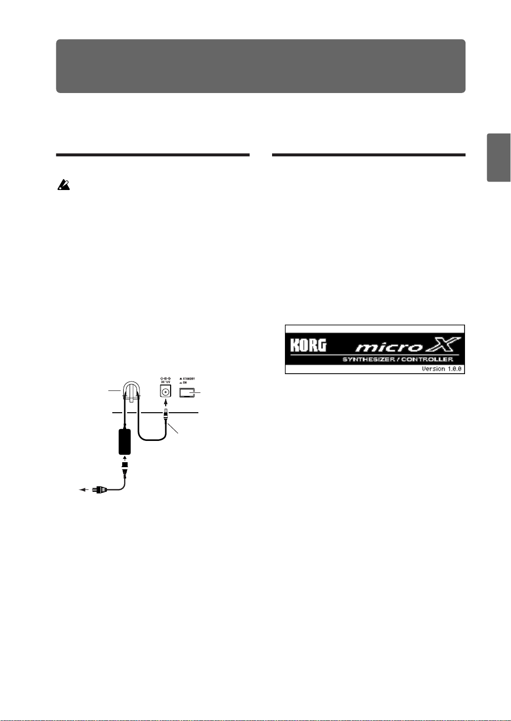
1. Connect the plug of the included AC adapter to
the power connector on the microX’s rear
panel.
2. Connect the power cable to the AC adapter.
3. Plug the power cable into an AC outlet.
4. To prevent the plug from being pulled out
accidentally, wrap the AC adapter cable
through the cable hook located on the rear of
the microX. Be careful not to bend the base of
the plug unnecessarily.
Connecting the AC adapter
4 Cable hook
AC adapter
2
Plug into an AC
outlet
Power switch
1 Power connector
Be careful not to
bend this portion
excessively when you
wrap the cable
through the cable
hook.
Turning the power on
1. Turn the microX’s [VOLUME] knob towar d the
left.
If you have connected powered monitor
speakers or a stereo amp, turn down the
volume of these devices.
2. Press the rear panel Power switch to turn on
the power.
The display will show the model name,
software version.
(The following graphic shows the factory-set
display. The version number is subject to
change without notice.)
3. Turn on your powered monitors or stereo amp.
4. Turn the microX’s [VOLUME] knob to an
appropriate position, and adjust the volume of
your powered monitor speakers or stereo amp.
Note: The state of microX when the power is
turned on will depend on the setting of “Power
On Mode” (GLOBAL 0: System, Pr efer ence page).
(☞p.88)
Combination
MultiEffectGlobalArpeggiatorDrum Kit
3 Power cable
External control
Other functions
Appendices
23
Page 30

Setup
Turning the power off
After you’ve finished editing, be sure to write
(save) your changes.
If you edit a program and then select a
different program or turn off the power, the
changes you made will be lost. The same is
true for a combination or multi set.
The settings you edit in Global mode are
remembered as long as the power is on, but
will be lost when you turn off the power.
1. Turn the microX’s [VOLUME] knob towar d the
left.
Also turn the volume of your powered monitor
speakers or stereo amp down to zero.
2. Turn off the power of your powered monitor or
stereo amp.
3. Press the rear panel Power switch to turn off
the power.
Never turn off the power while data is being
written into internal memory.
If the power is turned off while processing is
being performed, memory write operations
will not be completed correctly. If this occurs,
microX will automatically initialize its
internal memory so that it will operate
correctly. This is not a malfunction.
While data is being written, the display will
indicate “Now writing into internal memory.”
Data is written into internal memory by the
following operations.
•Writing (updating) a Program, Combination,
Multi, Global Setting, Drum Kit, Arpeggio Patterns, or External Control Setup
• Loading a Preload data for Program, Combination, Multi, Global Setting, Drum Kit, Arpeggio
Patterns, or External Control Setup
• Receiving a MIDI data dump for Program,
Combination, Multi, Global Setting, Drum Kit
data, Arpeggio Patterns, or External Control
Setup
24
Page 31

Connections
Connections
Connections must be made with the power
turned off. Please be aware that careless
operation may damage your speaker system
or cause malfunctions.
Basic connections
Connect the audio cables as shown in the connection diagram below.
Connecting audio output devices
Here, you can connect a set of amplified monitor
speakers or your audio system to output microX’s
sound.
Connecting the MAIN OUTPUT L/MONO
and R
These are the main outputs. They are unbalanced
phone jacks.
These are the main stereo outputs; their volume is
controlled by the [VOLUME] knob. All of the factory Programs and Combis are programmed to
play through these outputs.
If you’re editing a program or combination, or
playing back from an external MIDI sequencer in
Multi mode, you can set “BUS Select” to “L/R” so
that the sound will be sent from these jacks.
1. Connect the (MAIN OUTPUT) L/MONO and
R jacks to the INPUT jacks of your powered
monitor system, mixer etc.
If you are outputting in stereo, make
connections to the L/MONO jack and the R
jack. If you are outputting in monaural, make
connections to the L/MONO jack. We
recommend that you playback in stereo if
possible.
If you’re playing back through a stereo audio
amp or a stereo radio-cassette player that has
external input jacks, connect these jacks to the
jacks marked LINE IN, AUX IN, or External
Input. (Y ou may need to use an adapter plug or
adapter cable.)
If you playback microX through your stereo
audio system, be aware that high volumes
may damage your speakers. Be careful not to
raise the volume excessively.
Connecting INDIVIDUAL OUTPUT 1 and 2
If desired, you can connect these two individual
(independent) outputs. They are unbalanced
phone output jacks.
These jacks allow you to send the microX’s sounds
to external equipment independent of the (MAIN
OUTPUT) L/MONO and R jacks. This can be convenient when recording, or when using a complex
live performance setup.
1. Connect the (INDIVIDUAL OUTPUT) 1 and 2
jacks to the input jacks of your mixer etc.
Note: The [VOLUME] knob does not affect the
volume of jacks 1 and 2.
Note: The sound will be sent from these jacks if
you set “BUS Select” to 1, 2, or 1/2.
Quick StartIntroductionSetupProgram
Combination
MultiEffectGlobalArpeggiatorDrum Kit
Audio output device connections
Headphones
Powered monitors
INPUTINPUT
Power switch
RL/MONO
External control
Other functions
PHONES
Appendices
25
Page 32

Setup
L/MONO
Headphones
Mixer
1
R
PHONES
2
Powered monitors
INPUTINPUT
Headphones
1. When using headphones, plug them into the
headphones jack located on the front panel.
Use the [VOLUME] knob to adjust the volume
of the headphones. The microX’s headphone
jack carries the same signal as the (MAIN
OUTPUT) L/MONO and R output jacks.
Note: If you want to monitor the (INDIVIDUAL
OUTPUT) 1 and 2 jacks in addition to the main
outputs, an external mixer may be required.
Connecting a damper pedal, foot switch, or foot pedal
By connecting an optional damper pedal, foot
switch, or foot pedal, you can control even more
functions and effects.
PEDAL
Connecting a damper pedal
This pedal can provide a damper effect as you
play. This instrument also supports half-damping.
Here’s how to connect an optional Korg DS-1H
damper pedal to the DAMPER jack and use it to
control the half-damper effect.
1. Connect an separately sold DS-1H damper
pedal to the DAMPER jack.
You’ll be able to control the half-damper effect
if you’ve connected the DS-1H. If you’ve
connected a different switch-type pedal, it will
function as a damper switch.
2. After you turn on the power, set the switch
polarity and adjust the half-damper response to
ensure that the half-damper pedal works
correctly. (☞PG p.77, 80)
SWITCH DAMPER
26
Connecting a foot switch
If you connect an on/off-type foot switch such as
the Korg PS-1 pedal switch to the ASSIGNABLE
SWITCH jack, you can use it to turn the sostenuto
or soft pedal effect on/off, to turn the arpeggiator
on/off, to switch programs or combinations, to
control tap tempo, or to apply modulation to a
sounds or an effect.
This switch will always function in the same way
regardless of the program, combination, or multi
set you’ve selected. You can assign the function in
the Global mode 0: System, Foot page.
1. Connect a foot switch such as the separately
sold PS-1 to the ASSIGNABLE SWITCH jack.
2. After turning the power on, use GLOBAL 0:
System, Foot page “Foot SW Assign” and “Foot
SW Polarity” to assign the function controlled
by the foot switch and to specify the polarity.
(☞p.88)
Page 33

Connecting a computer
Connecting a foot pedal
If you connect a separately sold EXP-2 foot controller or XVP-10 expression/volume pedal to the
ASSIGNABLE PEDAL jack, you can use it to
apply modulation to sounds or effects, or to adjust
the overall volume.
This pedal will always function in the same way
regardless of the program, combination, or multi
set you’ve selected. You can assign the function in
the Global mode 0: System, Foot page.
1. Connect an separately sold XVP-10 or EXP-2 to
the ASSIGNABLE PEDAL jacks.
2. After turning the power on, use GLOBAL 0:
System, Foot page “Foot Pedal Assign” to
assign the function controlled by the foot pedal.
(☞p.89)
Connecting a computer
You can connect the microX to your computer and
use it as both an input keyboard and a MIDI
sound module.
You can also use the included editor to edit the
microX from your computer.
You can connect the microX to your computer in
either of the following ways.
• Use a USB cable
Note: Use the KORG USB-MIDI Driver if you’re
connecting the microX via USB to a computer
that meets the requirements described in
“KORG USB-MIDI Driver operating
requirements,” below.
• Use a commercially available MIDI interface,
and connect the microX via its MIDI connectors.
Operating requirements for the
KORG USB-MIDI Driver and the editor software
Quick StartIntroductionSetupProgram
Combination
MultiEffectGlobalArpeggiatorDrum Kit
Contents of the CD-ROM
microX Editor/Plug-In Editor
(for Windows XP / Mac OS X)
KORG USB-MIDI Driver
(for Windows XP / Mac OS X)
microX External Control Template
Parameter Guide (PDF)
Editor/Plug-In Editor Manual (PDF)
microX External Control Template List (PDF)
Software License Agreement (PDF)
Please note before use
• Copyright to all software included in this product is the property of Korg Inc.
• The license agreement for this software is provided separately. You must read this license
agreement before you install this software.
Your installation of this software will be taken
to indicate your acceptance of this agreement.
KORG USB-MIDI Driver operating
requirements
Windows:
• Computer
A computer with a USB port, that satisfies the
requirements of Microsoft Windows XP
27
External control
Other functions
Appendices
Page 34

Setup
• Operating system
Microsoft Windows XP Home Edition,
Professional or x64 Edition (The driver for x64
Edition is a Beta version.)
Macintosh:
• Computer
An Apple Macintosh with a USB port that
satisfies the requirements of Mac OS X
• Operating system
Mac OS X version 10.3 or later
Please be aware that in the case of some
computers, the system may not function
correctly even if your computer meets the
above requirements.
microX Editor/Plug-In Editor operating
requirements
You must install the KORG USB-MIDI Driver
if you want to connect the microX to your
computer via USB and use the microX Editor/
Plug-In Editor.
It is not possible to run multiple instances of
microX Editor/Plug-In Editor on the
operating system. This means that it is not
possible to use these editors to edit two or
more microX units simultaneously.
Windows XP:
Installing the KORG USB-MIDI Driver
and the editor software
microX/X50 application installation
The microX application installer automatically
installs the KORG USB-MIDI Driver Tools and
microX Editor/Plug-In Editor that are provided
on the included CD-ROM.
Note: You must install the KORG USB-MIDI
Driver Tools before you connect the microX to
your computer via USB.
1. Insert the included CD-ROM into your CD-
ROM drive.
Normally the “microX/X50 Application
Installer” will start up automatically.
If your computer is set so the installer does not
run automatically, double-click
“KorgSetup.exe” on the CD-ROM.
2. From the list, select [KORG microX
SYNTHESIZER/CONTROLLER], and click
[Next >].
Windows:
• Computer
CPU: Pentium III/1 GHz or better
Memory: 256 MB or more
Monitor: 1,024 × 768 pixels, 16-bit color or
better
A computer with a USB port, that satisfies the
requirements of Microsoft Windows XP
• Operating system
Microsoft Windows XP Home Edition or
Professional, Service Pack 1 or later
Macintosh:
• Computer
CPU: Apple G4/400 MHz or better
Memory: 256 MB or more
Monitor: 1,024 × 768 pixels, 32,000 colors or
better
An Apple Macintosh with a USB port that
satisfies the requirements of Mac OS X
• Operating system
Mac OS X version 10.3.9 or later
3. From the list, select the applications that you
want to install, and click [Install].
If you want to install the preloaded application
template files for external control, click
“microX External Control templates” to select
it.
The applications you selected will be
successively installed.
4. Follow the on-screen instructions to install each
application.
28
Page 35

Connecting a computer
If you’ve made settings as shown in the screen
shot for step 2, the KORG USB MIDI Driver
Tools Installer screen will appear first.
• Click [Next >].
• The “License agreement” will appear. Carefully read the contents, and if you agree,
check “I accept the terms of the license agreement” and click [Next>].
• Specify the installation destination. The
screen will show the installation destination
folder. If you want to change this, click
[Change] and select the desired installation
destination.
• Click [Next >] to begin the installation.
• When the installation is complete, click [Finish] to exit the installer.
Install the next application in the same way.
5. If you selected microX Editor/Plug-In Editor in
step 2, choose the application(s) you want to
install.
• Successively select and install the Editor
(Standalone), Plug-In Editor (VST), and/or
Plug-In Editor (RTAS) as desired.
For example if you want to install the standalone version, click [Install Stand-alone
version]. Then follow the on-screen
directions to perform the installation, and
click [Close] when the installation has been
successfully completed.
If you want to install a plug-in version, click
in the Installer screen to select the format of
plug-in that you want to install, and perform
the installation.
• When you’ve finished installing the application(s) you want, click [Exit installer] to exit
the installer.
6. When all the selected applications have been
installed, click [Finish] to exit the installer.
7. The first time you connect the microX to the
USB port of your computer, the standard USBMIDI driver provided by Windows will be
installed automatically.
If you want to use the KORG USB-MIDI Driver
for Windows XP, please re-install the driver
manually using the procedure described below.
Setting up the KORG USB-MIDI Driver
1. Before you perform the procedure below, you
must finish installing KORG USB-MIDI Driver
Tools into your computer.
Then restart the operating system of your
computer, and power-on the microX. (☞p.23)
Note: The driver must be installed for each USB
port. If you connect the microX to a different
USB port than the one you used when
installing KORG USB-MIDI Driver for
Windows, you will need to use the same
procedure to install the driver again.
2. Using a USB cable, connect the USB connector
of the microX to the USB connector of your
computer.
Make sure that the plug is oriented correctly,
and push it all the way into the connector.
Windows will detect that the microX has been
connected.
Quick StartIntroductionSetupProgram
Combination
MultiEffectGlobalArpeggiatorDrum Kit
External control
Other functions
29
Appendices
Page 36

Setup
Then the standard driver will be installed
automatically.
3. In the task bar, choose [Start] → [All Programs]
→ [KORG] → [KORG USB-MIDI Driver Tools]
→ [Install KORG USB-MIDI Device] to start up
the setup utility.
The KORG USB-MIDI devices currently
connected to your computer will be shown in
the list above. The lower area will show the
version of the KORG USB-MIDI Driver that
you will be installing. Select microX in the list
above, and click [Install]. Driver installation
will begin.
Note: For details on installation and setup, and on
uninstallation, see the “Installation manual”
(HTML) on your computer. To view the
“Installation manual,” click from your taskbar’s
[Start] → [All Programs] → [KORG] → [KORG
USB-MIDI Driver Tools] → [Installation manual].
About the microX and driver ports
KEYBOARD port
Applications on your computer use this port to
receive MIDI messages from the microX (data
from the keyboard and controllers).
SOUND port
Applications on your computer use this port to
send MIDI messages to the microX’s internal
sound generator, making it produce sound.
Setting up the microX Editor/Plug-In
Editor
For details on setting up and using the microX
Editor/Plug-In Editor, see “Editor/Plug-In Editor
Manual” (PDF).
4. If a warning dialog box regarding digital
signature authentication appears during the
installation, click [Continue] to continue the
installation.
5. Driver installation has been completed. Click
[Finish] to exit the installer. If you are asked
whether you want to restart Windows now,
choose [Yes] to restart.
About the microX external control templates
See “microX External Control Template List”
(PDF) for details on the control change (CC#) settings assigned by the preloaded external control
templates and the application settings to which
they correspond.
30
Page 37

Connecting a computer
Mac OS X:
Installing the KORG USB-MIDI driver
and editor software
Installing the KORG USB-MIDI Driver
Note: Use the KORG USB-MIDI Driver if you are
connecting the microX via USB to a computer that
satisfies the conditions listed in “KORG USB-MIDI
Driver operating requirements” (☞p.27).
1. Insert the included CD-ROM into your CD-
ROM drive.
2. In the CD-ROM, navigate to the “KORG USB-
MIDI Driver” folder, and double-click “KORG
USB-MIDI Driver.pkg” to start up the installer.
3. Depending on the version of your operating
system, a confirmation dialog box may appear
at this point. If so, enter your password and
click [OK]. When the installer starts up, the
following screen will appear. Click [Continue].
4. “Import information” will appear. Read the
contents, and click [Continue].
5. The “License agreement” will appear. Carefully
read the contents, and click [Continue].
A dialog box will ask whether you accept the
terms of the license agreement. If you accept,
click [Agree].
6. A screen where you can choose the
“Installation destination” will appear. Choose
the installation destination and click
[Continue].
7. The “Easy Installation” dialog box will appear.
Click [Install].
8. Depending on the version of your operating
system, a confirmation dialog box may appear
at this point. If so, enter your password and
click [OK].
9. When the installation has been successfully
completed, click [Close] to exit the installer.
About the microX and driver ports
KEYBOARD port
Applications on your computer use this port to
receive MIDI messages from the microX (data
from the keyboard and controllers).
SOUND port
Applications on your computer use this port to
send MIDI messages to the microX’s internal
sound generator, making it produce sound.
Installing the microX Editor/Plug-In Editor
To install the software in Mac OS X, pr oceed as follows.
1. Insert the included CD-ROM into your CD-
ROM drive.
2. In the CD-ROM, navigate to the “microX
Editor” folder , and double-click “micr oX Editor
Installer.pkg” to start up the installer.
3. Follow the on-screen instructions to install
application.
See “Installing the KORG USB-MIDI Driver.”
4. When the installation has been successfully
completed, click [Restart].
Note: If you’re using Mac OS X, the plug-in version
will also be installed in the appropriate folder.
Setting up the microX Editor/Plug-In
Editor
For details on setting up and using the microX
Editor/Plug-In Editor, see “Editor/Plug-In Editor
Manual” (PDF).
Quick StartIntroductionSetupProgram
Combination
MultiEffectGlobalArpeggiatorDrum Kit
Installing the microX External Control
Temperate
To install the software in Mac OS X, pr oceed as follows.
1. Insert the included CD-ROM into your CD-
ROM drive.
2. In the “microX External Control” folder on the
CD-ROM, double-click “microX External
Control.pkg” to start up the installer.
31
External control
Other functions
Appendices
Page 38

Setup
3. Follow the on-screen instructions to install
application.
See “Installing the KORG USB-MIDI Driver”
(☞p.31).
4. When the installation has been successfully
completed, click [Close] to exit the installer.
About the microX external control templates
See “microX External Control Template List”
(PDF) for details on the control change (CC#) settings assigned by the preloaded external control
templates and the application settings to which
they correspond.
Connecting via the microX’s USB
connector, and setting-up
USB connector (for connecting to computer)
If you connect the microX’s USB connector to your
computer, you’ll be able to send and receive note
data and other performance information and
sound settings between your computer and the
microX as MIDI messages.
Note: The USB connector of the microX is only able
to transmit and receive MIDI data.
Note: Use the KORG USB-MIDI Driver if you’re
connecting the microX via USB to a computer that
meets the requirements described in “KORG USBMIDI Driver operating requirements.”
1. Using a USB cable, connect the USB connector
of the microX to the USB connector of your
computer.
Make sure that the plug is oriented correctly,
and push it all the way into the connector.
Computer
USB cable
USB
microX
2. Make the necessary settings in the microX’s
Global mode.
See “Global mode settings on the microX,”
below.
Connecting to your computer via
MIDI
Here’s how to connect the microX to your computer via a commercially available MIDI interface.
1. Connect the microX’s MIDI OUT connector and
MIDI IN connector to your computer via the
MIDI interface.
For details on how to use your MIDI interface,
see its owner’s manual.
Some models of USB-MIDI interface may be
unable to transmit or receive the microX’s
MIDI exclusive messages.
Computer
2. Make the necessary settings in the microX’s
Global mode.
See “Global mode settings on the microX,”
below.
MIDI interface
microX
MIDI OUT
MIDI IN
MIDI INMIDI OUT
Global mode settings on the microX
Local Control On settings
Turn on the Echo Back function of the external
MIDI/USB sequencer or computer (so that data
received at MIDI IN will be re-transmitted from
MIDI OUT/USB), and turn off the microX’s Local
Control setting (so that microX’s keyboard and
tone generator will be internally disconnected).
When you play the keyboard of the microX, the
musical data will be transmitted to the external
MIDI sequencer or computer, and then echoed
back to play the microX tone generator. In other
words, by turning Local Control OFF, you can prevent notes from being sounded in duplicate, as
would otherwise occur if a note were sounded by
the microX’s own keyboard and again by the data
that was echoed-back.
If the arpeggiator function is on, playing the
microX’s keyboard will not cause the arpeggiator
to operate, and only the musical data produced by
playing the keyboard will be transmitted. The
arpeggiator will operate only in response to the
notes that are echoed-back and received at MIDI
IN. In this way, turning off Local Control prevents
the arpeggiator from operating in duplicate.
Use this setting when you wish to record on the
external MIDI sequencer or computer only the
notes that trigger the arpeggiator, and to use the
32
Page 39

Connecting a computer
echoed-back notes to operate the arpeggiator
while monitoring your recording or during playback.
Note: If you want the note data produced by the
arpeggiator to be recorded on the external
sequencer/computer, set Local Control on, and
turn off the Echo Back setting of the external
sequencer/computer.
The default setting for Local Control is On. To turn
off Local Control, the “Local Control On” (GLOBAL 1: MIDI page) check box to uncheck it (☞PG
p.82).
When using the microX by itself, leave Local Control turned on. (If this is off when microX is used
by itself, playing the keyboard will not produce
sound.)
Note: The microX’s Local Control setting can be
turned Off by the Local Control Off message sent
from the editor when you start up microX Plug-In
Editor.
Arpeggiator
Keyboard
Trigger
Sound generator section
OFF ON
MIDI IN
USB
MIDI OUT
USB
This connection
is broken when
you turn Local
Control off.
MIDI IN
MIDI OUT
USB
USB
Sequencer or
computer
(Echo Back on)
MIDI Filter “Exclusive” setting
If you want the microX to transmit and receive
system exclusive data, you must check the GLOBAL 1: MIDI page MIDI Filter “Exclusive” check
box. Check this box if the microX is connected to
your computer and you want to edit the microX
from your computer (or bi-directionally). You
must also check this box if you’re using the
microX Editor/Plug-In Editor. By default, the
MIDI Filter “Exclusive” setting is checked.
The “Convert Position” setting
On the microX, the parameters “Key Transpose”
and “Velocity Curve” (GLOBAL 0: System, Basic
page) allow you to transpose the pitch, adjust the
velocity sensitivity.
The “Convert Position” setting (GLOBAL 1: MIDI
page) specifies the point at which these settings
affect the data from the keyboard and the data
sent or received via MIDI IN/USB or MIDI OUT/
USB.
• When controlling an external MIDI tone gener-
ator from the microX, select Pre MIDI. The
above-listed settings will affect the MIDI data
that is transmitted.
Incoming MIDI data will be handled with
settings equivalent to “Key Transpose” 0 and
“Velocity Curve” 4.
• When controlling the microX’s tone generator
from an external MIDI device, select PostMIDI.
The above-listed settings will affect the MIDI
data that is received.
Outgoing MIDI data will be handled with
settings equivalent to “Key Transpose” 0 and
“Velocity Curve” 4.
The default settings are “Key Transpose” +00,
“Velocity Curve” 4 (Normal), and “Convert Position” PreMIDI.
“Multi Mode” setting
You will normally use Multi mode when you’re
using the microX as a multi-timbral sound module
to simultaneously play multiple tracks from an
external MIDI sequencer. However, you can also
use Multi mode when you want to use the microX
as a master keyboard to control an external MIDI
sound module. (Normally you will use Combination mode if you’re using the microX as a master
keyboard.)
Depending on which of these two situations
describes your needs, you can set the “Multi
Mode” setting in the GLOBAL 0: System, Preference page so that the microX will operate optimally for your situation.
for Ext-Seq is the setting you should choose when
using the microX as a multi-timbral sound module. When you switch multi sets on the microX,
tracks whose “Status” is EXT or BTH will not
transmit MIDI messages such as program
changes. This will avoid the undesired situation of
the echo back from your external MIDI sequencer
switching microX tracks of the identical channel to
the same program, pan, and volume settings etc.
for Master is the setting you should choose when
using the microX as a master keyboard. In this
case when you switch multi sets on the microX,
tracks whose “Status” is EXT or BTH will transmit
program changes and other MIDI messages to set
up your external MIDI sound module.
Making settings in Global mode
Here’s how to set parameters in Global mode.
1. Press the [GLOBAL] button (the button will
light) to enter Global mode.
2. Press the [MENU/OK] button to access the
page menu.
33
Quick StartIntroductionSetupProgram
Combination
MultiEffectGlobalArpeggiatorDrum Kit
External control
Other functions
Appendices
Page 40

Setup
3. Use the ClickPoint [√][®][π][†] to select a
page, and press the ClickPoint center.
• Local Control On
• MIDI Filter Exclusive
• Convert Position
Choose “MIDI” if you want to make these
settings.
The GLOBAL 1: MIDI page will appear.
• Multi Mode
Choose “System” if you want to make these
settings.
One of the GLOBAL 0: System pages will
appear. Use the [PAGE+][PAGE–] buttons to
select the Preference page.
Example connections when using
the microX Editor/Plug-In Editor
If you want to mix the microX’s audio signals with
the audio signals sent from your host application
via your audio interface, or with audio signals
from another sound module, make connections as
shown below.
Powered monitors
INPUTINPUT
Audio interface
USB cable
USB cable
L/MONO
1
R
USB
2
Computer
microX
4. Use the ClickPoint [√][®][π][†] to select the
parameter whose setting you want to change.
For “Local Control On” or “Exclusive,” select
the parameter and press the ClickPoint center
to switch the parameter on/off.
For the “Local Control On” parameter, local
control will be off when the box is unchecked.
For “Convert Position” and “Multi Mode,”
select the parameter and turn the [VALUE] dial
to change the setting.
If you want to apply a plug-in effect to the
microX’s audio signals, or to control the microX’s
audio signals in your host application together
with the audio data from the KORG Legacy Collection or other audio tracks, make connections as
shown below . Make settings as appr opriate for the
host application you’re using.
For details on setup, see “Editor/Plug-In Editor
Manual” (PDF).
Powered monitors
INPUTINPUT
Audio
interface
L/MONO
1
R
2
USB
USB cable
Computer
microX
34
Page 41

Connecting MIDI devices
Connecting MIDI devices
By connecting the microX’s MIDI connectors to an
external MIDI device you can transfer sound settings and performance data such as note messages
between your external MIDI device and the
microX.
About MIDI
MIDI stands for Musical Instrument Digital Interface, and is a world-wide standard for exchanging
various types of musical data between electronic
musical instruments and computers. When MIDI
cables are used to connect two or more MIDI
devices, performance data can be exchanged
between the devices, even if they were made by
different manufacturers.
MIDI connectors
MIDI IN:
This connector receives MIDI data.
Use this to play the microX from another MIDI
device, or from an external sequencer.
Controlling microX’s tone generator
from an external MIDI device
When you wish to play or control the microX’s
tone generator from an external MIDI keyboard or
sequencer etc., use a MIDI cable to connect the
MIDI OUT connector of the external MIDI device
to the MIDI IN connector of microX.
MIDI IN
microX
MIDI OUT
MIDI keyboard
Controlling two or more external
MIDI tone generators from microX
You can also use a MIDI patch bay to control multiple MIDI devices.
microX
MIDI IN
MIDI IN
MIDI OUT
MIDI OUT
Quick StartIntroductionSetupProgram
Combination
MultiEffectGlobalArpeggiatorDrum Kit
MIDI OUT:
This connector transmits MIDI data.
Use this to control external MIDI devices, or to
record into an external sequencer.
Controlling an external MIDI tone
generator from microX
When you wish to use the microX’s keyboard,
controllers, and arpeggiator etc. to play an external MIDI tone generator, use a MIDI cable to connect microX’s MIDI OUT connector to the MIDI
IN connector of the external MIDI tone generator.
MIDI OUT
microX
MIDI IN
MIDI keyboard
MIDI patch bay
MIDI OUT
MIDI IN
MIDI tone generator
MIDI keyboard
Connecting an external MIDI
sequencer
You can connect the microX to your external MIDI
sequencer and use it both as an input keyboard
and as a MIDI sound module.
1. Connect the microX’s MIDI OUT connector to
your MIDI sequencer’s MIDI IN connector, and
connect the sequencer’s MIDI OUT connector
to the microX’s MIDI IN connector.
2. Make the necessary settings in the microX’s
Global mode.
See “Global mode settings on the microX”
(☞p.32).
MIDI
sequencer
MIDI IN
MIDI OUT MIDI IN
MIDI OUT
External control
Other functions
microX
Appendices
35
Page 42

Setup
36
Page 43
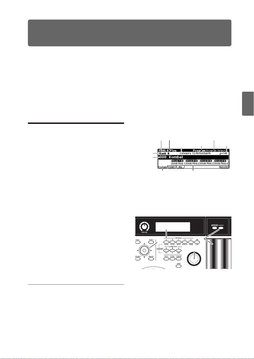
Playing and Editing Programs
Quick StartIntroductionSetupProgram
What’s a Program?
Programs are the basic sounds of the microX.
Programs are important elements of other modes
as well. In Combination mode you can combine
multiple programs to create complex sounds, and
in Multi mode you can play multiple programs by
Playing programs
Selecting programs
There are several different ways to select programs. Each one is convenient in a different way:
• Selecting programs from the front panel:
Using “Program Select” to select a program
·Turn the [VALUE] dial.
·Press the center of the ClickPoint to highlight the field, then use [π][†] to select a
program, and press the center to finalize
your selection.
· Use the PROGRAM [A]–[GM] buttons to
select a program bank.
Selecting programs by program category
You can select programs by categories such as
piano or drums. (☞p.38)
• Selecting programs by using a foot-switch:
You can change programs even while both
hands are busy playing on the keyboard convenient for live applications.
• Selecting programs by receiving MIDI program changes:
You can switch programs from an external
MIDI sequencer or an external MIDI controller.
See below for details.
Selecting programs from the front
panel
1. Press a PROGRAM [A]–[GM] button. (The
button will light.)
You will enter Program mode, and the bank
you specified will be selected. Notice that the
upper line of the display indicates “PROG 0:
Play” (mode name, page number and name).
receiving MIDI messages from multiple tracks of
your MIDI sequencer or other DAW program.
This section of the manual takes a quick look at
playing Programs, including tours of the frontpanel controllers and basic editing techniques.
The bank number you specified is shown below
“PROG 0: Play.”
Mode name Page number and name
Bank
number
Program
Select
(program
number
and name)
2. Make sure that “Program Select” (program
number and name) is selected.
If this is not selected, use the ClickPoint [π][†]
to highlight the “Program Select” indication.
3. Use the [VALUE] dial etc. to select the program
you want to play.
You can use the following methods to select a program.
•Turn the [VALUE] dial.
•Press the center of the ClickPoint to highlight
the field, then use [π][†] to select a program,
and press the center to finalize your selection.
4. Press a PROGRAM [A]–[GM] button to switch
banks.
When you select a different Bank, the button’s
LED will light, and the selected bank will
appear on the left side of the display.
Category number
and name
Knob B assign listTab
1, 4
2
3
Tab name
5
Parameter name
Tempo
37
Combination
MultiEffectGlobalArpeggiatorDrum Kit
External control
Other functions
Appendices
Page 44

Playing and Editing Programs
For example, to select bank B, press the
PROGRAM [B] button. The [B] button will
light, and the name Bank B will appear in the
left of the display.
• Each time you press the [GM] button, the bank
will alternate as shown below.
G→g(d)→G→g(d)→G…
Auditioning the sound
5. Play a note on the keyboard to hear the sound
you selected.
Alternatively, you can press the [AUDITION]
button (the button will light) to turn on the
Audition function and the microX will
automatically play a riff (phrase) suitable for
the selected program.
Overview: Program Banks
When shipped from the factory, it is loaded with
640 Programs. You can also save any programs
that you create.
Programs are organized into six banks as shown in
the following table.
Program banks
Prog.
Bank
A, B,
C, D, E
G
g(d)
No.
000…
127
001…
128
001…
128
for
preloaded
programs
GM
programs
GM2 drum
programs
Explanation
With the factory settings, these
banks contain a wide variety of
preloaded programs that use
the internal PCM ROM
multisamples, effects, and
arpeggio patterns.
128 programs can be written or
rewritten to each bank (for a
total of 640).
These banks contain 128 GM
programs and nine GM drum
programs that are compatible
with the GM sound map. The
programs of these banks are
read-only.
Bank G contains the GM
programs. G lets you select 128
programs numbered from 001–
128, and g(d) lets you select
nine drum programs.
You can’t write (save) data to
these banks.
Selecting by Category
You can select Programs from within a category,
such as keyboard, organ, bass, and drums.
When shipped from the factory, the preloaded
Programs are organized into 16 categories.
In the PROG 0: Play page you can select programs
by category as follows.
Using [CATEGORY] and the PROGRAM/
COMBINATION buttons to select
1. Press the [CATEGORY] button.
The category menu will appear. The categories
are displayed in the left side of the screen, and a
list of the programs in the selected category are
displayed in the right side.
Sel (Select)Category No.
Category Program
2. Press the PROGRAM [A]–[GM] or COMBINATION
[A]–[C] button for the desired category.
The category you specify will be selected. A
category name is printed below each bank
button.
Note: This method lets you select up to nine
categories.
•You can use the [PAGE+][PAGE–] buttons to
step through the categories one by one.
3. By using the [VALUE] dial or the ClickPoint
[π][†] to select programs, you can step
through the programs in the same category.
4. Press the [MENU/OK] button to confirm your
selection. If you decide not to select a program,
press the [EXIT/CANCEL] button.
2
1
38
3
4
3
Note: You can also switch categories by using the
ClickPoint [√][®] to select “Category No.” in the
top line of the category menu and then turning the
[VALUE] dial.
Page 45

Selecting programs
Using a footswitch to select Programs
You can assign a footswitch to step through Programs one by one, either going up (0, 1, 2, 3, etc.)
or going down (3, 2, 1 etc.).
This lets you change Programs without using your
hands–great for quick Program changes in live
performance situations.
To set this up:
1. Connect a foot switch to the rear-panel
ASSIGNABLE SWITCH jack.
Use a simple on/off footswitch, such as the
optional KORG PS-1.
2. Press the [GLOBAL] button to enter Global
mode.
3. Press the [EXIT] button to access the GLOBAL
0: System page.
4. Press the [PAGE+] button to access the Foot tab.
5. Select “Foot SW Assign,” and specify either
Program Up or Program Down.
Program Up lets you select the next higher
program number each time you press the foot
switch.
Program Down lets you select the next lower
program number each time you press the foot
switch.
6. Set the “Foot SW Polarity” to the polarity of the
pedal you’ve connected.
If you’ve connected a separately sold PS-1
pedal switch, choose the (–) KORG Standard
setting.
With these settings, you will step through the
programs one at a time each time you press the
foot switch.
If you want this setting to be remembered even
after you turn off the power, be sure to write
the changes you made. (☞p.45)
7. Use the PROGRAM [A]–[GM] buttons to enter
PROG 0: Play, and press the foot switch; the
program will change.
Note: This setting applies to selecting Combinations,
as well.
Using MIDI program change messages to select programs
By sending MIDI program change messages along
with MIDI bank select messages to the microX
from an external MIDI device (a MIDI sequencer
such as a DAW program, or a MIDI controller,
etc.), you can select any program in the seven
banks.
You can also install the included “microX Plug-In
Editor” into your DAW program as a plug-in, and
easily select microX programs or combinations
from a list within your DAW. For more details, see
“Editor/Plug-In Editor Manual” (PDF).
MIDI channel setting
In order to play the microX via MIDI, the transmitting device (MIDI sequencer or computer) and
receiving device (the microX) must be set to the
matching MIDI channel. In Program mode, the
microX receives data on the global MIDI channel.
1. Make sure that the microX and your external
MIDI device or computer are connected
correctly.
For details on connections, see p.27.
2. Press the [GLOBAL] button to enter Global
mode.
3. Press the [MENU] button to access the PAGE
MENU.
4. Use the ClickPoint [√][®][π][†] to select
“MIDI,” and press the center.
The GLOBAL 1: MIDI page will appear.
5. Use the ClickPoint [√][®][π][†] to select
“MIDI Channel,” and use the [VALUE] dial to
specify the global MIDI channel.
With the default settings, the global MIDI
channel “MIDI Channel” is set to 01.
Selecting programs
To switch programs, send a MIDI program change
from your external MIDI device or computer.
To switch banks, send a Bank Select control
change message (CC#0: upper byte, CC#32: lower
byte). The microX will switch to the program of
the specified bank at the time that it receives a program change following the bank select message.
Quick StartIntroductionSetupProgram
Combination
MultiEffectGlobalArpeggiatorDrum Kit
External control
Other functions
39
Appendices
Page 46

Playing and Editing Programs
microX
Bank #
A0 – 127 63 0 0 – 127
B0 – 127 63 1 0 – 127
C0 – 127 63 2 0 – 127
D0 – 127 63 3 0 – 127
E0 – 127 63 4 0 – 127
G
g(d)
microX
Program #
1 – 128 121 0, 1 – 9 0 – 127
1 – 128: R 56 0 0 – 127
1 – 128: (XG) R 0 0, 1 0 – 127
1 – 128: (GS) R
1 – 128 120 0 0 – 127
1 – 128: R 62 0 0 – 127
Bank
Select
CC#0
Bank
Select
CC#32
000 – 127
100 – 127
Program #
Note: In bank G, program numbers 000 through
127 correspond to 001–128.
Note: “R” (Receive) indicates that only reception is
supported.
Note: Bank select messages will not be transmitted
or received if the GLOBAL 1: MIDI page MIDI
Filter “Bank” is unchecked.
Note: The table above describes the operation with
“Bank Map” set to GM. For details on the KORG
mapping (☞PG p.78).
Using Controllers
The microX provides realtime contr ollers such as a
joystick and OCTAVE [†][π] buttons that let you
make your performances more expressive.
These controls let you modify the tone, pitch, volume, effects, etc. in realtime while you play.
For example, a piano sound can be played realistically using only the keyboard, but your performance will be more expressive if you connect a
damper pedal. If you’re playing guitar or wind
instrument sounds, you can use the joystick to
control the pitch or to apply vibrato.
Note: In the pages that follow, our explanation will
center on the dedicated functionality of each
controller. However, you can also use these
controllers as sources for “alternate modulation”
or “effect dynamic modulation,” giving you a
much wider range of possible uses than we
describe here. For details on these capabilities, see
“Using Alternate Modulation” (☞p.51) and PG
p.151.
Keyboard
Velocity
How hard you play the keyboard affects the expressiveness of the sound. You can adjust the volume
level setting so that playing the keyboard softly will
produce a soft sound, and playing hard will produce a loud sound. In addition, you can also adjust
the brightness of the sound and the envelope settings such as attack rate and release time.
Using Velocity Switch in Combination Play mode
and Multi mode, you can play different Programs
by changing the keyboard velocity.
• See PROG 6: Ed–Amp1/2, Mod (☞p.55, PG
p.21) for information on how to change the volume level and envelope using key velocity.
• See PROG 4: Ed–Filter1/2, Basic, Mod.1
(☞p.54, PG p.16) for information on how to
change the brightness and tonal color of the
sound using key velocity.
• See PROG 2: Ed–Pitch, OSC1/2 (☞PG p.10) for
information on how to control the pitch change
using key velocity.
Note Number
Sounds can be programmed to change in character
based on the note being played. As you play
higher or lower on the keyboard, the note number
can modulate the timbre–such as becoming
brighter as you play higher. Envelopes may also
become faster or slower; the volume may change;
and so on.
Joystick
You can use the joystick to vary the pitch or adjust
the depth of modulation. The actual result will
depend on the program, but these controllers are
normally used to apply the following effects.
+Y
Deepen the vibrato
–X
Lower the
pitch
–Y
Deepen the wah effect
• Joystick movement in the +X/–X axis can
adjust the amount of pitch bend
PROG 2: Ed–Pitch, OSC1 (☞p.52, PG p.10)
+X
Raise the
pitch
40
Page 47

Using Controllers
• Joystick movement in the +X/–X axis can vary
the cutoff frequency
PROG 4: Ed–Filter1/2, Mod.2 (☞PG p.16)
• Joystick movement in the +Y axis can adjust the
depth of vibrato
PROG 2: Ed–Pitch, OSC 1/2 LFO (☞p.52, PG
p.11)
• Joystick movement in the –Y axis can adjust the
depth of the wah effect
PROG 4: Ed–Filter1/2, LFO Mod. (☞p.54, PG
p.18)
• Joystick movement in the +Y axis can adjust the
speed of the LFO
PROG 3: Ed–LFOs, OSC 1/2 LFO 1/2 (☞PG
p.14)
OCTAVE
These buttons shift the range of pitches assigned
to the keyboard in one-octave steps over a range
of ±3 octaves.
Pressing the [π] button will raise the pitch in oneoctave steps. Pressing the [†] button will lower
the pitch in one-octave steps.
You can press the OCTAVE [†][π] buttons simultaneously to recall the written (saved) settings.
OCTAVE [†][π] functions
Press the
[†]
button
† C6 – C8 Rapid blinking π
† C5 – C7 Slow blinking π
† C4 – C6 Lit π
† C3 – C5 Dark π
† C2 – C4 Lit π
† C1 – C3 Slow blinking π
† C0 – C2 Rapid blinking π
Press the [†][π]
simultaneously
Keyboard
range
buttons
† + π Written value
LED status
Keyboard
range
Note: With the factory settings, changing the
program, combination, or multi set will also recall
the OCTAVE [†][π] button setting that was
written as part of that data. This is because the
GLOBAL 0 “OCTAVE Keys [†/π]: Use Prog/
Combi/Multi’s Octave” setting is checked. If this
setting is not checked, changing the program etc.
will not affect the OCTAVE [†][π] setting until
you change the octave yourself. (☞p.88)
Press the
[π]
button
LED status
Corresponds to
pitch range
REALTIME CONTROLS [1], [2], [3], [4],
[SELECT]
Use the [SELECT] button to select realtime controller mode A/B/C, and use knobs [1]–[4] to control the tone, effects, MIDI control changes, and
arpeggiator etc. while you perform.
Specifically, you can use these controllers to edit
the filter cutoff frequency, resonance, amp and filter EQ, volume, portamento time, pan, pitch LFO,
and master effect send level, etc. You can also use
them to modify the arpeggiator tempo, gate,
velocity, and length. For more details, see p.43 and
p.91.
1. Press the REALTIME CONTROLS [SELECT]
button to switch the function of the realtime
controllers to A-mode, B-mode, or C-mode.
2. Rotate the desired knob to control the sound,
etc.
The REALTIME CONTROLS [1], [2], [3], and [4]
knob B-mode functions can be viewed for Program
mode in the 0: Play, Program page; for Combination mode in the 0: Play, Combination page; and
☞
for Multi mode in the 0: Play, Multi page. (
p.37)
Note: If you turn the [EXT . CONTROLLER] button
on (lit), these knobs will be switched to the
external control function, and will be disconnected
from the internal sound generator. The
REALTIME CONTROLS [1]–[4] knobs will
transmit MIDI messages (as specified by the
external control setup) to your external MIDI
equipment.
Using the pedals for control
Damper Pedal (Sustain)
The damper pedal is also sometimes called the
sustain pedal. It acts like the similarly-named
pedal on an acoustic piano; when you hold down
the pedal, notes will continue to sustain even
when you lift your hands off of the keyboard.
Damper Switch vs. Half-Damper
You can use either a standard footswitch (such as
the Korg PS-1) or a special half-damper pedal
(such as the Korg DS-1H) as the Damper.
If you use a footswitch, it will work like a normal
synthesizer sustain pedal: notes will sustain forever, as long as the pedal is held down.
A half-damper pedal is a special type of continuous foot pedal (normal foot pedals won’t work
properly for this application). It offers mor e subtle
control of sustain, which can be especially useful
for piano sounds.
41
Quick StartIntroductionSetupProgram
Combination
MultiEffectGlobalArpeggiatorDrum Kit
External control
Other functions
Appendices
Page 48

Playing and Editing Programs
The microX will automatically sense when a halfdamper is connected to the rear-panel DAMPER
jack. For proper operation, you will also need to
calibrate the pedal, using the “Half Damper Calibrate” command in the Global page menu. (☞PG
p.77)
Assignable Foot Switch
This lets you use a simple footswitch, such as the
Korg PS-1, as an assignable controller. The footswitch can perform a wide variety of functions,
such as:
• Sound and effect modulation
• Portamento on/off
•Program select up or down
•Tap Tempo
• Arpeggiator on/off
• Duplication of many front panel controls,
including the modulation Joystick, Real-Time
Knobs
Functions other than the above “Sound and effect
modulation” will always operate as specified by
the GLOBAL 0: System, Foot page, regardless of
the currently selected program, combination, or
multi set.
For more information, see “Specifying the function of the ASSIGNABLE Switch and ASSIGNABLE Pedal” (☞p.88).
External control
You can use the REALTIME CONTROLS [1], [2],
[3], and [4] knobs to transmit MIDI messages. This
can be used to control a KORG Legacy Collection
software synthesizer or DA W pr ogram running on
your computer, or to control an external MIDI
device.
You can assign three control changes to each knob
and switch between them using the [SELECT] button, giving you a total of twelve different control
changes. These twelve assignments (four knobs x
three sets) are one “set,” and the microX provides
64 such sets. (☞p.111)
[EXT. CONTROLLER] button
This switches the external function on/off. If this
is on, the button will light and the realtime control
functions will be disabled.
When this is on, you can use the [SELECT] button
to select the MIDI messages assigned to the scene
and use the REALTIME CONTROLS [1], [2], [3],
and [4] knobs to send messages to your external
MIDI device.
When the external function is on, the REALTIME
CONTROLS [1], [2], [3], and [4] knobs operate
independently, and are not affected by the settings
of Program, Combination, or Multi mode.
Assignable Foot Pedal
This lets you use a continuous controller pedal,
such as the Korg EXP-2 foot controller or Korg
XVP-10 EXP/VOL pedal, as an assignable controller.
Like the Assignable Foot Switch, described above,
the Foot Pedal can be used for many different
functions, including:
• Master Volume
• Channel Volume, Pan, or Expression
• Assignable sound modulation, as several different AMS or Dmod sources
•Effects Send level control
• Duplication of many front panel controls,
including the modulation Joystick, Real-Time
Knobs
Functions above will always operate as specified
by the GLOBAL 0: System, Foot page, regardless
of the currently selected program, combination, or
multi set.
For more information, see “Specifying the function of the ASSIGNABLE Switch and ASSIGNABLE Pedal” (☞p.88).
Sending MIDI information from the
various controllers
When you operate a controller of the microX, the
corresponding or specified control change will be
transmitted via MIDI. Pitch bend messages are
transmitted only when you operate the joystick.
In Program mode, these messages are transmitted
on the global MIDI channel.
For details on the MIDI messages transmitted
when you operate an microX controller, and on the
AMS (Alternate Modulation Source) and DMS
(Dynamic Modulation Source) corresponding to
the MIDI messages, see “MIDI transmission when
the X50/microX’s controllers are operated” (☞PG
p.166).
42
Page 49

Simple program editing
Simple program editing
You can edit any of the Programs shipped with
microX, or you can start with an initialized Program to create sounds from scratch.
On the microX, you can use the eight sliders in the
Performance Editor display and the realtime controller knobs and switches of the front panel to
make simple changes to a program without having to enter the editing pages that contain the
detailed editing parameters.
Performance Edit
By using the eight sliders of the Performance Editor, you can make overall adjustments to the sound.
When you move a slider, multiple program
parameters are adjusted simultaneously, meaning
that you can edit multiple parameters by adjusting
a single slider.
1. In Program mode (PROG 0: Play page), select
the program that you want to edit.
2. Press the [PAGE+] button (or [PAGE–] button)
to access the PROG 0: Play, Perform. Edit page.
Amp Level: Indicates the amp level. This will
adjust the volume of the entire program.
Attack Time: Indicates the attack time of the
filter EG and amp EG. This will adjust the
speed of the attack from note-on.
Note: In order to maximize the effect of the
Attack Time adjustment, the amp EG Start
Level, Attack Level, Start Level Modulation,
and Attack Time Modulation parameters are
also adjusted.
Decay Time: Indicates the decay time and
slope time of the filter EG and amp EG.
IFX Balance: This simultaneously adjusts the
“W/D (Wet/Dry)” balance of all insert effect.
MFX Balance: This simultaneously adjusts the
Return 1 and 2 parameters of the master effects.
Note: Depending on the settings of the program
parameters, the result may not be noticeable.
5. If you want to save the modified sound, select
the utility menu command “Write Program,”
and write the program. (☞p.45)
The edited content will be lost if you select
another program or turn off the power before
saving.
Quick StartIntroductionSetupProgram
Combination
MultiEffectGlobalArpeggiatorDrum Kit
3. Use the ClickPoint [√][®][π][†] to select the
performance editor parameter you want to
adjust.
4. Use the [VALUE] dial etc. to adjust the value.
(☞p.20)
Octave: Indicates the octave setting.
Pitch Stretch: Simultaneously adjusts the
transpose and tune settings of the oscillator.
This allows you to produce a variety of tonal
changes without losing the character of the
original sound.
This is particularly effective for acoustic-type
programs such as guitar, bass, or piano. Select
various programs and try this out.
OSC Balance: Adjusts the level balance
between oscillators 1 and 2.
Note: For programs whose “Mode (Oscillator
Mode)” (PROG 1: Ed–Basic, Prog Basic page)
setting is Single, oscillator 2 will not sound.
Only the level of oscillator 1 will change. For a
Drums program, this performance editor will
have no effect.
REALTIME CONTROLS [1], [2], [3], [4], [SELECT]
The REALTIME CONTROLS [1]–[4] knobs can be
used to edit parameters such as the filter cutoff frequency, resonance, the amp and filter EGs, volume, portamento time, pan, LFO speed and more.
Three different modes - A, B, and C - allow each
knob to control one of three separate parameters.
The REALTIME CONTROLS [1]–[4] knobs can
transmit MIDI messages (as specified by the external control setup) to your external MIDI equipment. If you turn the [EXT. CONTROLLER]
button on (lit), these knobs will be switched to the
external control function, and will be disconnected
from the internal sound generator. For more about
external control, see “External control settings”
(☞p.111).
1. Press the REALTIME CONTROLS [SELECT]
button to switch the function of the realtime
controllers to A-mode, B-mode, or C-mode.
Each time you press the button, A-mode, Bmode or C-mode will be selected alternately,
and the corresponding LED will light.
43
External control
Other functions
Appendices
Page 50

Playing and Editing Programs
Note: If CC#70–79 are assigned to REALTIME
CONTROLS A-mode or B-mode, the sound edited
by knobs [1]–[4] can be saved by the Program
Write operation (☞p.45).
[SELECT] button
Knobs [1]–[4]
2. Rotate the desired knob to control the sound,
etc. See the explanations that follow.
A-mode controls
In A-mode, knobs [1]–[4] will control/edit the following functions.
Note: Placing the knobs in the center (12 o’clock)
position will produce the values specified by the
program parameters.
Knob [1]: LPF CUTOFF
Adjust the cutoff frequency of the low pass filter.
When you adjust the cutoff frequency of the filter,
the brightness of the sound will change. The effect
will depend on the settings of the program parameters, but normally, rotating the knob toward the
left will darken the sound, and rotating it toward
the right will brighten it.
Level
Adjusting the cutoff frequency of the high-pass filter will modify the thickness of the sound from
which the low frequency range has been filtered
out.
Level
LPF HPF
Cutoff
frequency
Knob [3]: EG-INTENSITY
Adjust the filter EG intensity (the depth at which
the filter EG is applied).
Rotating the knob will affect the depth of the filter
EG. Normally, rotating the knob toward the left
will make the filter EG apply less deeply, and
rotating it toward the right will make the filter EG
apply more deeply. Since the filter EG will operate
based on the cutoff frequency of the filter, knobs
[1] and [3] will work together to control the tonal
changes produced by the filter.
Level
Time
LPF
Frequency
Low
Cutoff
frequency
High
Knob [2]: RESONANCE/HPF
Adjust the resonance level of a low pass filter or
the cutoff frequency of a high pass filter.
The content that is controlled will depend on the
filter type specified by the program.
By adjusting the filter resonance level, you can
increase or decrease the resonance level to add a
unique character to the sound.
44
Knob [4]: EG-RELEASE
Adjust the EG release times of the filter and amp.
This will determine the time from note-off until
the sound disappears.
When you adjust the knob, the release times of the
filter EG and the amp EG will change. Normally,
rotating the knob toward the left will shorten the
release time, and rotating it toward the right will
lengthen the release time.
Page 51

Saving your edits
note-on
Level
Attack Level
Decay Time
Attack Time
Start Level
Break Level
Sustain Level
Slope Time
note-off
Release Time
Release Level
Time
B-mode controls
You can control parameters such as volume, portamento time, pan or filter and amp EG, pitch LFO,
and master effect send levels etc.
The B-mode function settings are made for each
individual program, combination, or multi set.
You can specify the B-mode functions separately
for each individual program, combination, or
multi set.
The B-mode functions of the REALTIME CONTROLS [1], [2], [3], and [4] knobs can be viewed
for Program mode in the 0: Play, Program page,
for Combination mode in the 0: Play, Combination
page, and for Multi mode in the 0: Play, Multi
page. (☞p.37)
Each knob in B-mode can also be used as a source
for Alternate Modulation or Effect Dynamic Modulation to control program parameters or effect
parameters, allowing you to adjust the sound in a
wide range of ways.
C-mode control
You can control the effect of the arpeggiator in
realtime.
For details on operation, see p.91.
Saving your edits
Once you’ve tweaked the sound to perfection,
you’ll want to save your work. To save your edits:
Be aware that if you modify the sound of a
program or write it to a different bank or
number , and then use a combination that uses
the modified program, the combination will
sound different.
1. Press the [UTILITY] button to access the utility
menu.
2. Use the ClickPoint to select “Write Program,”
and then press the ClickPoint center.
The Write Program dialog box will appear.
Note: If the display indicates “Memory
Protected,” the program memory protect is
turned on. Go to GLOBAL 0: System,
Preference page, and uncheck the Memory
Protect “Program” setting. (☞p.88)
3. Optionally, you can also select a new location,
or change the Program’s name.
• If you want to change the bank and number of
the writing destination, use the ClickPoint to
select the program name located at the right of
the “T o,” and use the [VALUE] dial to select the
desired writing destination.
Note: You can’t save in banks G or g(d).
• If you want to change the name, use the ClickPoint to select the text button ( ) and then
press the ClickPoint center to open the text edit
dialog box.
You can give the Program a descriptive name
using the on-display keyboard. (☞p.114)
After entering the name, press [MENU/OK]
button.
The text edit window will disappear, returning
you to the main Write dialog.
• If you want to specify the category, use the
ClickPoint to select “Category,” and use the
[VALUE] dial to specify the desired category.
The category you specify here can be used
when selecting by category with the
[CATEGORY] button.
You can select by Category in the following
pages.
PROG 0: Play page
COMBI 0: Play, Prog page “Program Select”
COMBI 1: Ed–Tone Adjust, Prog page
MULTI 0: Play, Program page.
4. In the Write Program dialog box, press the
[MENU/OK] button to write (save) the
program.
5. A message will ask you for confirmation. If you
are sure you want to write the program, press
the [MENU/OK] button once again.
The program will be written (saved).
45
Quick StartIntroductionSetupProgram
Combination
MultiEffectGlobalArpeggiatorDrum Kit
External control
Other functions
Appendices
Page 52

Playing and Editing Programs
Detailed Editing with Programs
You can create your own original sounds by editing the factory Programs, or by initializing a Program (Bank E 127: Init. Program
and starting from
)
scratch. You can save these Programs into any
bank other than Bank G or g(d), which cannot be
modified.
Before you begin editing
The three attributes of sound: pitch,
tone, and volume
Sound has three basic attributes; pitch, tone, and
volume.
To control these attributes, the microX provides
“oscillator,” “filter,” and “amp (amplifier)” sections.
The “oscillator” settings vary the pitch, the “filter”
settings modify the tone, and the “amp” settings
modify the volume.
The microX’ s “ oscillator,” “filter ,” and
“amp”
On the microX, the settings that determine the
“pitch” are located in the PROG 1: Ed–Basic and
PROG 2: Ed–Pitch pages. In the Ed–Basic page
you can specify the waveform (multisample) and
the basic pitch of the waveform. In the Ed–Pitch
page you can specify how the pitch will follow the
keyboard, and make other pitch-related settings.
“Filter” settings are made in the PROG 4: Ed–
Filter1 and PROG 5: Ed–Filter2 pages. These settings adjust the tone.
Finally, “Amp” settings are made in the PROG 6:
Ed–Amp1/2 pages. These settings adjust the volume, and send the sound to the outputs.
Program structure and corresponding pages
These three sections determine the basic sound of
the program.
EG, LFO, keyboard tracking, AMS,
Dmod, controllers
In addition to the sections described above, the
microX provides ways in which the sound can be
varied according to time, key range, or various
types of performance expression. These are controlled by modulators and controllers such as EG
(envelope generator), LFO (Low Frequency Oscillator), keyboard tracking, AMS (Alternate Modulation Source), Dmod (Dynamic modulation) and
the joystick. You can use these modulators and
controllers to apply change to the basic sound of
the program.
Take a look at the diagram entitled “Program
structure and corresponding pages.” Notice that
the audio signal flows in the order of Oscillator/
Pitch → Filter → Amp. Also notice how modulators such as EG and LFO can affect these blocks.
As shown in figure, a program consists of OSC 1/
2, effects, and the arpeggiator.
OSC 1/2
Each timbre consists of Oscillator/Pitch, Filter,
Amp, EG, and LFO blocks. You can create more
complex programs by using two oscillators
together in one program using the Layer feature.
Note: The Pitch EG is shared by OSC1 and OSC2.
EFFECTS
The output of OSC 1/2 is sent to the insert effect,
the master effects, and the master EQ. The mixer
section lets you control the routing, so you can
specify where the sound will be sent.
Program Basic : 1-1
Oscillator1 Basic : 1-2, 4
OSC1 Pitch Mod. : 2-1, 2
Oscillator / Pitch
46
OSC1 LFO1 : 3-1
Filter1 Mod. : 4-2,3
Filter1 LFO Mod. : 4-4
Pitch EG : 2-5
OSC1 LFO2 : 3-2
Filter1(A/B) : 4-1
Amp1 Mod. : 6-2
Filter1 EG : 4-5
Filter
Amp1 Level/Pan : 6-1
Amp1 EG : 6-3
OSC 1
OSC 2
Amplifier
Insert Effect :
8-1
OSC1, 2
Insert Effect
Master Effect
IndividualOutput
Insert Effect:
8-2, 3
1–1, 9–4, etc. indicate the microX on-screen pages and tabs.
Master Effect 1, 2:
9-1...3
Effect
MasterEQ : 9-4
Controller Setup:
7-3
Arpeggiator :
7-1, 2
AUDIO OUTPUT
L/MONO, R
AUDIO OUTPUT
INDIVIDUAL 1, 2
Page 53

Before you begin editing
For the one insert effect and the two master effects,
you can choose from 89 effect types. The master
EQ is a stereo three-band EQ.
ARPEGGIATOR
A program can use one arpeggiator . You can select
an arpeggio pattern, specify the range in which
the arpeggio will be generated, and specify the
range of notes (keys) and velocities that will trigger the arpeggiator.
Overview of editing pages
In the PROG 0: Play page you can select and play
programs, and use the performance editor or realtime controllers to make simple edits to the sound.
You can also adjust the arpeggiator settings.
The other pages let you modify the sound in more
detailed ways.
•Select and play programs.
0: Play
1: Ed–Basic
2: Ed–Pitch • Pitch settings. Pitch EG settings.
3: Ed–LFOs
4: Ed–Filter1
5: Ed–Filter2
6: Ed–Amp1/2
7: Ed–Arp/Ctrls
8: Ed–InsertFX
9: Ed–MasterFX
•Use the Performance Editor for easy
editing, and to do simple editing of
arpeggio patterns.
•Select an external control set.
•Specify the program type as Single,
Double, or Drum.
•Select multisamples.
•Specify Mono or Poly voice assignment.
•Select the temperament (e.g., equal
temperament).
•Type and speed settings etc. for the two
LFOs provided for each oscillator. (Make
settings in the pitch, filter, and amp
pages to specify the depth of the LFO
settings you make here.)
•Filter (tone) settings. Filter EG settings.
•Settings related to Amp 1/2 (volume),
including amp EQ and pan (stereo
position).
•Arpeggiator settings. (Shared with 0:
Play parameters. You may edit either.)
•Controller settings.
•Select the BUS and master effect send
level for the oscillator output.
• Insert Effect routing, selection and
settings.
•Master Effect selection and settings.
Master EQ settings.
Comparing (original and edited
sounds)
When you’re in the process of editing a sound,
pressing the [COMPARE] button will recall the
saved version of the sound, as it was before you
started editing. To indicate that you are listening
to the saved version, the button’s LED will light
up.
Pressing [COMPARE] button again returns you to
the version you are editing, and the LED will go
out again.
If you edit while the COMPARE LED is lit, the
button will again go dark and your previous edits
will be lost.
Quick StartIntroductionSetupProgram
Combination
MultiEffectGlobalArpeggiatorDrum Kit
External control
For details on how to access each mode, page, and
the utility commands, and how to edit values, see
“Basic operations” (☞p.19).
Other functions
Appendices
47
Page 54

Playing and Editing Programs
Basic oscillator settings
Program type setting (single, double, drum kit)
Here you can specify the type of program
(whether to use one oscillator, two oscillators, or a
drum kit). Use the PROG 1: Ed–Basic, Prog Basic
“Oscillator Mode” to specify the program type.
Single Programs have one oscillator, and Double
Programs have two oscillators. Each oscillator
includes a complete synthesis voice, with velocityswitched Multisamples, dual filters, EGs, LFOs,
and so on.
Drums mode is a special variation of Single mode,
and uses a Drum Kit (as created in Global mode)
instead of Multisamples.
EGs will not re-trigger, so that you can move from
note to note in a true legato fashion. If the previous note is released before the next note is played,
the note will trigger normally.
Try switching between Poly and Mono, and listen
to the results.
Working with Multisamples
What is a multisample?
A sample is a digital recording of a particular
instrument or waveform (or other natural or artificially processed sound) recorded at a specific
pitch. A multisample is a collection of similarly
voiced samples, used to create the same type of
sound - piano, bass, guitar, strings, organ - across
the entire keyboard, as the basis of a pr ogram. The
oscillators of single and double programs use multisamples. There are 624 multisamples available in
this instrument.
You can assign up to two multisamples to each
oscillator and switch between them by velocity.
This is called “velocity multisample switching.”
Polyphony
Polyphony is the number of notes that can be
played simultaneously, such as in a chord. The
polyphony depends on the program type.
Program type Polyphony
Single 62
Double 31
Drums 62
Polyphonic/monophonic playing
The Voice Assign Mode selects whether the Program will play polyphonically (Poly) or monophonically (Mono).
When this is set to Poly, you can play both chords
and melody lines. When this is set to Mono, only
one note will sound even if you play a chord.
Normally you’ll set this to Poly, but Mono is use-
ful when playing sounds such as synth basses,
synth leads, and other solo instruments. Another
important aspect of monophonic playing is Legato
triggering. When Legato is on (the box is checked),
if a new note on the keyboard is played before the
previous note is released, the filter and amplifier
Multisamples and Drum Kits
Multisamples and Drum Kits allow you to play
samples in different ways.
• Multisamples lay out one or more samples
across the keyboard. For instance, a very simple
guitar Multisample might have six samples–
one for each string.
• As the name suggests, Drum Kits are optimized
for playing drum samples.
Selecting Multisamples
If you specify a High and Low multisample for an
oscillator , either the High or the Low multisample
will sound depending on the velocity of the note
(i.e., the strength at which you play the keyboard).
This function is called velocity multisample
switching.
Note: To make it easier for you to hear the result,
set the program type to “Oscillator Mode” Single.
1. Access the PROG 1: Ed–Basic, OSC1 page.
2. Use the ClickPoint [√][®][π][†] to highlight
“High Multisample.”
• Use the [VALUE] dial to make your selection.
48
Page 55

Basic oscillator settings
• Alternatively, you can select a multisample by
category.
With “High Multisample” highlighted, press
the [CATEGORY] button to access the category
menu. (☞p.38)
Use the [PAGE+][PAGE–] buttons to select a
category.
Then use the [VALUE] dial to select a
multisample.
Press the [MENU/OK] button to finalize your
selection.
3. Specify the basic pitch of the oscillator. This is
set by the “Octave” parameter.
4. In the same way, select a different multisample
for “Low Multisample.”
You have now assigned the “High” and “Low”
multisamples. Next we’ll set the velocity range.
5. Specify a velocity value for “Velocity SW
L→H.”
Notes played on the keyboard at a velocity less
than the value you specify will sound the Low
multisample; velocities at or above this velocity
value will sound the High multisample.
For example if you set “Velocity SW L→H” to
100, playing the keyboard softly will sound the
“Low” multisample, and playing strongly will
sound the “High” multisample.
6. Adjust the “Level” for High and Low
multisamples to set their volume balance.
Note: If you do not wish to use this function, set
the “Velocity SW L → H” value to 001. Only the
High multisample will sound.
Reverse check box
Reverse lets you play the selected multisample
backwards, without looping. This can produce
interesting results for sound effects or other
unusual timbres.
Normally you will not check
this.
Using oscillators 1 and 2 to create a
detuned sound
You can use a double program (i.e., a program
whose “Oscillator Mode” is Double) to create a
detuned sound as follows.
1. Make the same multisample and EG settings,
etc. for OSC1 and OSC2.
It will be convenient to use the Utility “Copy
Oscillator” to make the oscillator settings
match each other.
2. Specify the playback pitch for OSC1 and OSC2.
The playback pitch can be set independently.
By using the same multisample with slightly
different “Tune” settings, you can “detune” the
oscillators to produce a richer sound. Generally
speaking, people hear flat notes as sounding
“sour” or out of tune more easily than they do
sharp notes. So when detuning two oscillators,
it may sound more musical to tune one
oscillator up in pitch, and leave the other
oscillator close to or just slightly below normal
pitch.
Using velocity to switch between oscillator 1 and 2
Here you can specify the range of velocities that
will sound oscillators 1 and 2.
In the example shown above, the velocity ranges
are as follows.
• OSC1 will sound for all velocity values.
• OSC2 will sound only for strongly played notes
(64 and above).
•You can use Velocity Multisample Switching in
addition to this (☞“High Multisample, Low
Multisample”). For this example, set “OSC1” in
“Velocity SW L→H” to 32 and “OSC2” to 96.
The settings are shown as vertical lines in the
velocity zone display.
In this example, the multisamples will sound
over four levels.
Velocity values 001–031:
sound only the OSC1 Low multisample.
Velocity values 032–063:
sound only the OSC1 High multisample.
Velocity values 064–095:
sound the OSC1 High multisample and the
OSC2 Low multisample.
Velocity values 096–127:
sound the OSC1 High multisample and the
OSC2 High multisample.
49
Quick StartIntroductionSetupProgram
Combination
MultiEffectGlobalArpeggiatorDrum Kit
External control
Other functions
Appendices
Page 56

Playing and Editing Programs
Copying settings between OSC1 &
OSC2
Many of the Program parameters can be set differently for OSC1 and OSC2.
These include all of the parameters on:
• All of the tabs on the Ed–Pitch page, except for
the Pitch EG
• All of the tabs on the Ed–Filter page
• All of the tabs on the Ed–Amp page
• All of the tabs on the Ed–LFOs page
You can use the utility menu’s Copy Oscillator
command to copy these parameters from one
Oscillator to another. You can even copy parameters from an Oscillator in a different Program.
This command is useful when you want to set
both Oscillators to the same settings, or when you
want to duplicate settings you’ve used before.
Assigning a drum kit
What is a drum kit?
If you want to use a drum kit in a program, set the
“Oscillator Mode” to Drums. Then choose one of
the 40 user drum kits or nine GM-compatible
drum kits for the program to use.
A drum program uses a “drum kit” for its oscillator. A drum kit consists of multiple drum instrument samples placed across the keyboard. There
are 929 drum instrument samples. (☞p.48 “Multisamples and Drum Kits”)
In Global mode you can create or edit a drum kit
itself. You can assign up to two drum samples
(High and Low) to each note of the keyboard, and
switch between these drum samples by velocity.
You can also specify the effects and the routing to
the audio output jacks. (☞p.108 “Editing Drum
Kits”)
Selecting a drum kit
1. Access the PROG 1: Ed–Basic, Prog Basic page.
2. Set “Oscillator Mode” to Drums.
5. Specify the basic pitch of the oscillator. For a
drum kit, set “Octave” to +0 [8'].
Using LFOs and Envelopes (EGs)
Using LFOs
Each Oscillator has two LFOs: LFO1 and LFO2.
You can use these LFOs to modulate many differ-
ent Program parameters, including:
• Pitch (vibrato): PROG 2: Ed–Pitch, OSC1 LFO
“Intensity,” and the same parameter of the
OSC2 LFO
• Filter (wah effect): PROG 4: Ed–Filter1, LFO
Mod. “Intensity to A” and “to B,” and the same
parameters for PROG 5: Ed–Filter2
•Volume (auto-tremolo): PROG 6: Ed–Amp1/2,
Mod, LFO1 Mod. “Intensity,” and the same
parameters for LFO2 Mod.
In addition to the uses described above, you can
use an LFO as a source for Alternate Modulation
and Effect Dynamic Modulation to modulate a
wide range of parameters. By assigning an LFO to
“Pan AMS” (PROG 6: Ed–Amp1/2, Level/Pan)
you can create an auto-pan effect.
Basic LFO settings
Note: Depending on the program you’ve selected,
you may be unable to hear the result of the
following edits. If so, increase the value of one of
the “Intensity” parameters listed above so that
you can hear the result.
For example in order to use OSC1 LFO1 to modulate filter 1, you should increase the PROG 4: Ed–
Filter1, LFO Mod. LFO1 “Intensity to A” or “Intensity to B” value.
1. Access the PROG 3: Ed–LFOs, OSC1 LFO page.
3. Access the PROG 1: Ed–Basic, OSC1 page.
4. Use the ClickPoint [√][®][π][†] to highlight
“Drum Kit.”
Use the [VALUE] dial to select a drum kit.
50
2. Select the “Waveform” parameter.
3. Use the [VALUE] dial etc. to select the desired
LFO waveform.
The display shows a graphic of the waveform.
Page 57

Using Alternate Modulation
There are a number of waveforms to choose
from. Each are suited to different applications:
Triangle and Sine are the classic LFO shapes
for vibrato, tremolo, panning, and filter wah
effects.
Square is useful for gated filter and amp
effects, and creates a police siren effect when
modulating pitch.
The Guitar waveform is designed especially for
guitar vibrato, since it bends only upwards
from the base value.
Saw and Exponential Saw Down are good for
rhythmic filter and amp effects.
Random 1 (S/H) creates the classic sample-andhold effect, which is great for modulating a
resonant filter.
4. After looking at the different waveforms, select
Triangle.
5. Use the “Frequency” parameter to set the speed
of the LFO.
6. Use the “Fade” and “Dly” (Delay) settings to
control the way the LFO sounds at the
beginning of the note.
For more information on LFOs, see “PROG 3: Ed–
LFOs” (☞PG p.14).
All of these parameters control the way that the
LFO itself works. In order for the LFO to actually
affect the sound, you can use the dedicated LFO
routings on the Filter, Pitch, and Amp pages, or
use the LFOs as AMS sources for a wide variety of
parameters.
Frequency Modulation
AMS can be used to vary the LFO speed. This lets
you change the LFO speed by operating a controller , or by the EG or Keyboard Track settings. (☞PG
p.14)
MIDI/Tempo Sync.
If “MIDI/Tempo Sync” is checked, the “Frequency” setting will be ignored, and the LFO will
synchronize to the system tempo, as set by the
TEMPO knob or external MIDI clocks.
This lets you produce vibrato, wah, auto-pan, or
tremolo effects that lock to arpeggiator, or external
MIDI sequencers.
EGs (Envelope Generators)
An envelope creates a modulation signal by moving from one level to another over a specified time,
and then moving to another level over another
period of time, and so on.
Each program includes three EGs, one for Pitch,
one for the Filter, and one for the Amp. These produce time-varying changes in pitch, tone, and volume respectively. They can also be used to
modulate a number of other Program parameters
via AMS.
Attack Level
note-on note-off
Level
Attack Time
Start Level
Decay Time
Break Level
Sustain Level
Slope Time
Release Time
Release Level
Time
Using Alternate Modulation
AMS (Alternate Modulation Source) refers to any
of the assignable modulation sources in microX,
including:
• Built-in physical controllers, such as the Joy-
stick, and Real-Time Knobs
• Incoming MIDI controllers
• Modulators such as the Filter, Pitch, and Amp
EGs, or the LFOs
Intensity is a parameter that sets the degree
(speed, depth, amount etc.) to which AMS will
control the modulation.
A number of frequently-used modulation routings, such as using the joystick to vary the pitch,
are provided as additional, dedicated routings,
separate from AMS.
Note that not all AMS sources may be available for
some modulation destinations.
For details on alternate modulation and AMS, see
“Alternate Modulation Source (AMS)” (☞PG
p.151).
Suggestions on using AMS
When making settings for alternate modulation,
think of the effect that you wish to produce, what
type of modulation will be necessary to produce
that effect, and what parameter of the oscillator,
filter, or amplifier needs to be controlled.
Next, select a source (AMS) and set the Intensity.
If you proceed logically in this way, you will
achieve the desired effect.
For example, if you want to control a guitar sound
so that it approaches feedback when you move the
joystick, you might set up the joystick to modulate
the filter frequency and resonance.
51
Quick StartIntroductionSetupProgram
Combination
MultiEffectGlobalArpeggiatorDrum Kit
External control
Other functions
Appendices
Page 58

Playing and Editing Programs
Controlling Pitch
Here you can specify how the pitch of the multisample selected for the oscillator will change.
Pitch EG and LFO settings allow the pitch to varied over time.
Note: To specify the basic pitch of the multisample,
use the “Octave” parameter in the PROG 1: Ed–
Basic, OSC1 or OSC2 page.
Varying the pitch according to keyboard position (Pitch Slope)
On keyboard instruments such as piano or organ,
the pitch will rise as you play toward the right
side of the keyboard, and fall as you play toward
the left.
You can use the “Pitch Slope” setting to specify
how this will occur.
With positive (+) settings, the pitch will rise as you
play toward the right side of the keyboard. With
negative (–) settings, the pitch will fall as you play
toward the right side of the keyboard.
Normally you will leave this set to +1.0.
pitch will change over a longer time. With a value
of 000, there will be no portamento.
Creating Vibrato
You can use an LFO to create vibrato.
LFO 1/2 Intensity sets the depth to which the
selected LFO will affect the pitch. With a setting of
+12.00, vibrato will produce a maximum of ±1
octave of pitch change.
“JS+Y Int” specifies the amount of vibrato that the
LFO will produce when the joystick is pushed
away from yourself.
“AMS Intensity” specifies the depth of the vibrato
effect created by LFO when you operate an AMS
(Alternate Modulation Source). For example, suppose you set “LFO1 AMS” to KnobM1 [+] (Knob
Mod1: CC#17), and raise the “AMS Intensity.” If
Knob B Assign “Knob 1-B” is set to Knob Mod.1
(CC#17), vibrato will be applied when you turn
the microX’s knob [1] or when CC#17 is received.
Modulating the pitch
Pitch bend
The JS (+X) and JS(–X) settings specify the
amount of pitch change (in semitones) that will
occur when MIDI pitch bend messages are
received or when the joystick is moved to left or
right. A setting of +12 allows the pitch to be con-
trolled a maximum of one octave upward; a setting of –12 allows the pitch to be controlled a
maximum of one octave downward.
“Ribbon (#16)” specifies the amount of pitch
change (in units of a semitone) that will occur
when CC#16 is received (or when you operate the
ribbon controller of a connected TRITON Extreme
or similar device).
Portamento
Portamento makes the pitch change smoothly
when you play the next note before releasing the
previous note.
The “Time” parameter controls how long it take
the pitch to change. As this value is increased, the
Pitch EG
When the Intensity value is set to +12.00, the pitch
EG specified in the Pitch EG page will produce a
maximum of ±1 octave of pitch change.
To realistically simulate the slight change in pitch
that occurs when a string is plucked or at the
attack of a brass or vocal sound, you can use the
EG to create a subtle change in pitch at the attack.
52
Page 59

Using Filters
Using Filters
The filters allows you to diminish or emphasize
specified frequency areas of the sound.
The tone of the sound will depend significantly
on the filter settings.
microX provides Filter1 for OSC1 and Filter2 for
OSC2. For each of these filters, you can select from
two types (Low Pass Resonance or Low Pass &
High Pass). Filter2 can be used if “Mode (Oscillator Mode)” is set to Double.
Level
Overtones included
in the original multisample
Frequency (pitch)
Filter
Level
Filter T ypes
This selects the parts of the sound which will be
affected by the filter, as described below.
Low pass filter
This is the most common type of filter, which
passes the low frequency range and cuts the high
frequency range. When the overtones of the high
range are cut, a bright sound will become darker
(more mellow).
24 dB/oct and 12 dB/oct see the steepness of the
cut. 24 dB/oct means that the gain will decr ease 24
dB in one octave (i.e., as the frequency doubles). A
12 dB/oct filter would decrease the gain 12 dB in
one octave. The 24 dB/oct filter produces a steeper
cut.
Filter characteristics
Low Pass
Level
This area of overtones
will be diminished
Overtones after
passing through
the filter
Frequency (pitch)
12dB/oct
24dB/oct
Frequency
High pass filter
This type of filter passes the high frequency range
and cuts the low frequency range. Use this when
you wish to make the sound thinner. However if
the cutoff frequency (Frequency) is raised excessively high, the volume will become very low.
High Pass
Level
12dB/oct
Frequency
Resonance
When “Resonance” is set to a higher value, the
overtones in the region of the cutoff fr equency will
be boosted as shown in the diagram below, giving
a distinctive character to the sound.
When resonance is applied
Low Pass
Level
Low resonance
value
High resonance
value
When this is set to 0, there is no emphasis, and frequencies beyond the cutoff will simply diminish
smoothly.
At medium settings, the resonance will alter the
timbre of the filter, making it sound more nasal, or
more extreme. At very high settings, the r esonance
can be heard as a separate, whistling pitch.
To make the resonance track the keyboard pitch,
see “4–2a: Keyboard Track” (☞PG p.17).
Selecting a filter to modify the tone
Here’s how to select a filter type and adjust the
“Frequency” (cutoff frequency) and “Resonance”
(resonance level).
1. Use “Type” to select a filter type.
Low Pass Resonance: This is a 24 dB/octave
low pass filter with resonance.
Low Pass & High Pass: This is a 12 dB/octave
low pass filter and a 12 dB/octave high pass
filter connected in series.
2. If you’ve selected Low Pass Resonance as the
filter type, you can set the parameters for Filter
A.
“Frequency” specifies the cutoff frequency.
Overtones above the specified cutoff frequency
will be diminished, making the tone more
mellow (darker).
53
Quick StartIntroductionSetupProgram
Combination
MultiEffectGlobalArpeggiatorDrum Kit
External control
Other functions
Appendices
Page 60

Playing and Editing Programs
“Resonance” specifies the resonance level. This
boosts the overtones in the region of the
specified “Frequency,” giving the sound a
distinctive character.
If you’ve selected Low Pass & High Pass as the
filter type, you can use the Filter A parameters
to adjust the low pass filter and the Filter B
parameters to adjust the high pass filter.
Overtones above the Filter A “Frequency” will
be diminished, making the sound more mellow
(darker).
Overtones below the Filter B “Frequency” will
be diminished, decreasing the low-range and
making the sound thinner.
•“Int. to A” and “Int. to B” adjust the effect that
keyboard tracking will have on filters A and B.
For more details, see “4–2a: Keyboard Track”
(☞PG p.17).
Filter EG
The Filter EG is a multi-stage envelope, which you
can use to modulate the filter (naturally!) as well
as other Program parameters. The EG itself is set
up on the Filter page; the way that it affects the filters is controlled by the parameters described
below, on the Filter Mod page:
The “Int. to A” and “Int. to B” settings control the
basic amount of EG modulation for filter frequencies A and B, respectively, before other modulation.
The “Vel to A” and “Vel to B” settings let you use
velocity to scale the amount of EG modulation.
The “AMS” setting selects a AMS modulation
source to scale the amount of the Filter EG applied
to Filters A and B. The two filters share a single
AMS source, with separate intensity settings.
Modulating the filters
You can modulate the filter cutoff fr equency using
the Filter EG, the LFOs, keyboard tracking, and
other built-in and MIDI controllers. This is a great
way to add a rich variety of tonal change to the
sound.
Keyboard Track
Most acoustic instruments get brighter as you play
higher pitches. At its most basic, keyboard tracking re-creates this effect by increasing the cutoff
frequency of a lowpass filter as you play higher on
the keyboard. Usually, some amount of key tracking is necessary in order to make the timbre consistent across the entire range.
• When Ramp “Low” is set to a positive (+)
value, the cutoff frequency will rise as you play
lower on the keyboard, making the sound
brighter. When set to a negative (–) value, the
cutoff frequency will fall as you play lower on
the keyboard, making the sound darker.
• When Ramp “High” is set to a positive (+)
value, the cutoff frequency will rise as you play
higher on the keyboard, making the sound
brighter. When set to a negative (–) value, the
cutoff frequency will fall as you play higher on
the keyboard, making the sound darker.
LFO modulation
You can modulate the filter via LFO1 and LFO2.
Among other applications, LFO modulation of the
filter can produce the classic “auto-wah” effect.
The Ed–Filter1, LFO Mod (or Ed–Filter2) page lets
you set up the following parameters separately for
each LFO:
“Intensity to A” and “Intensity to B” specify how
much the LFO changes the tone.
“JS-Y Int. to A” and “JS-Y Int. to B” specify the
depth of the wah effect created by the LFO when
you move the joystick toward yourself or when
CC#2 is received.
The “AMS” setting selects a AMS modulation
source to scale the amount of the LFO applied to
Filters A and B. The two filters share a single AMS
source, with separate intensity settings.
For example if you set Knob B Assign “Knob 1-B”
to Knob Mod. 1 (CC#17), and set “AMS” to Knob
M1#17, you can turn the REALTIME CONTROLS
B-mode knob [1] to apply an auto wah effect.
54
Page 61

Using the Amp section
Quick StartIntroductionSetupProgram
AMS modulation
In addition to the EG, LFOs, and Key Track, you
can use two AMS sources to modulate the filters.
For instance, you could use the joystick to change
the brightness.
Using the Amp section
The Amp section includes contr ols for volume and
pan. You can control the volume using the Amp
EG, LFO 1/2, Keyboard Track, and velocity, along
with other AMS sources.
Each Oscillator has its own Amp section: Amp1
for OSC1, and Amp2 for OSC2.
Different sounds have characteristic shapes to
their volume levels.
For example, the volume of a piano note begins at
a high volume the instant you play the note, and
then decreases gradually.
The volume of an organ note, on the other hand,
remains constant as long as you continue pressing
the key.
The volume of a note on a violin or wind instrument can be varied during the note by the musician (i.e., by regulating the amount of pressure on
the bow or the force of the breath).
Volume Volume
Piano
Volume decays
gradually
Organ
Volume remains
constant until note
is released
Applying modulation to the amp
Keyboard Track
This lets you vary the volume relative to the note
you play.
For more details, see “Keyboard Track” (☞p.54).
Velocity (Amp Modulation)
Velocity Intensity is used by most programs to
decrease the volume of softly played notes and
increase the volume of strongly played notes.
Normally you will set Amp Modulation to positive (+) values. As this setting is increased, there
will be greater volume difference between softly
played and strongly played notes.
LFO1/2 Mod.
Specifies how the LFO’s will produce cyclic
changes in volume (tremolo effect).
The volume will be affected by the LFO(s) for
which you set an LFO1 Mod Intensity, LFO2 Mod
Intensity value.
Intensity (AMS Intensity) adjusts the depth by
which the tremolo effect produced by the LFO will
be affected when you assign an AMS (LFO1 AMS,
LFO2 AMS).
For example if you set “AMS” (LFO1 or LFO2) to
JS-Y #02, you can move the joystick toward yourself or receive CC#2 to apply a tremolo effect.
Combination
MultiEffectGlobalArpeggiatorDrum Kit
Time Time
Setting the basic amp level
The basic volume level is set by the “Amp Level”
parameter.
You can then alter this using the modulation
sources below:
Amp EG (Amp Envelope Generator)
The Amp EG lets you control how the volume
changes over the course of a note.
External control
Other functions
Appendices
55
Page 62
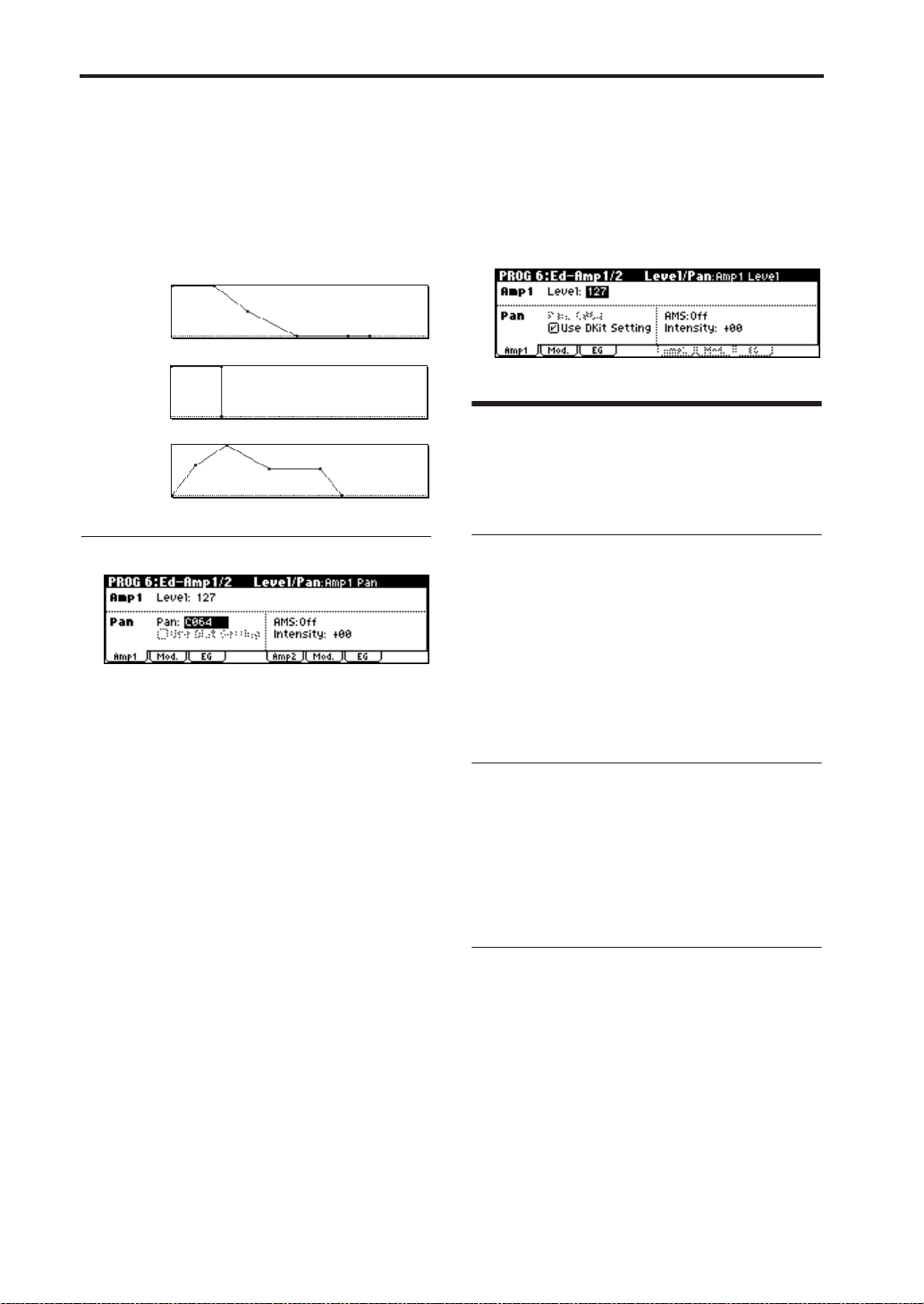
Playing and Editing Programs
Every instrument has its own characteristic volume envelope. This is part of what gives each
instrument its identifiable character.
Conversely, by changing the volume contour–for
instance, applying a string-like Amp EG curve to
an organ multisample– you can produce interesting and unusual sounds.
Piano
Organ
Strings
Adjusting the pan (stereo position)
The main “Pan” parameter determines the placement of the sound in the stereo field after the signal has passed through the oscillator, filter, and
amp.
Normally you’ll set this to C064, so that the sound
is centered equally between the left and right
speakers.
To create a stereo effect when “Oscillator Mode” is
set to Double, set the Amp1 “Pan” to L001, and
the Amp2 “Pan” R127. This will make OSC1 go to
the left speaker, and OSC2 go to the right speaker.
With a setting of Random, the pan will change
randomly each time you play a note on microX,
producing an interesting effect.
Pan AMS and Intensity
“Intensity” specifies the depth of the pan modulation from the selected AMS source.
If you set AMS to Note Number, the pan will
change according to the keyboard position of each
note played.
With a setting of LFO1 or 2, the sound will sweep
from side to side, creating an auto-pan effect.
If this is checked, the Program can use a different
pan position for each drum sound, as specified by
the Drum Kit. If this is unchecked, all drum
sounds will use the Program’s pan position. The
factory presets and GM drum kits use individual
pan positions for the different drums, so normally
it’s best to leave this checked.
Effects
Effects are covered in their own section of the
manuals, so we won’t go into too much detail
here. (☞p.79)
Insert Effect
You can make insert effect settings in the PROG 8:
Ed–InsertFX page.
The Insert Effect can be assigned to either an individual oscillator or the entire Program. You can
use any type of effects, from distortions and compressors to choruses and reverbs.
The Insert Effect can be routed to the main outputs, or to any of the individual outputs. (☞p.84)
Master Effects
You can make master effect settings in the PROG
9: Ed–MasterFX page.
There are two Master Effects, which are accessed
through Sends 1 and 2. These are best-suited to
effects such as reverbs and delays, but you can use
them with any type of effect. (☞p.85)
Master EQ
You can make master EQ settings in the PROG 9:
Ed–MasterFX page.
The master EQ is located immediately before the
(MAIN OUTPUT) L/MONO and R outputs. Use it
to adjust the overall tone. (☞p.85)
Pan - Use DKit Setting
Use DKit Setting applies when “Oscillator Mode”
is set to Drums.
56
Page 63

Playing and Editing Combinations
Quick StartIntroductionSetupProgram
What’s a Combination?
Combinations, or “Combis” for short, let you split
and layer up to 8 Programs at once.
A Combi is made up of 8 Timbres. Each Timbre
has a Program, along with parameters for key and
velocity zones, mixer settings, MIDI channel and
Playing combinations
Selecting combinations
There are several different ways to select Combinations. Each one is convenient in a different way:
• Selecting combinations from the front panel:
Using “Combi Select” to select a program
·Turn the [VALUE] dial.
·Press the center of the ClickPoint to highlight the field, then use [π][†] to select a
program, and press the center to finalize
your selection.
· Use the COMBINATION [A]–[C] buttons to
select a combination bank.
Selecting combinations by program category
You can select programs by categories such as
piano or drums. (☞p.38)
• Selecting combinations by using a footswitch:
You can change combinations even while both
hands are busy playing on the keyboard convenient for live applications
• Selecting combinations by receiving MIDI
program changes:
You can switch combinations from an external
MIDI sequencer or an external MIDI controller.
See below for details.
controller filtering, and so on.
As with Programs, each Combi has 1 Insert Effect,
2 Master Effects, and a Master EQ, for shaping and
transforming the sounds of the individual Timbres. Finally, Combis can use 2 Arpeggio patterns
modules at once.
Selecting combinations from the
front panel
1. Press a COMBINATION [A]–[C] button. (The
button will light.)
You will enter Combination mode, and the
bank you specified will be selected. Notice that
the upper line of the display indicates “COMBI
0: Play” (mode name, page number and name).
The bank number you specified is shown below
“COMBI 0: Play.”
Mode name
Bank
number
Combi
Select (combination
number and
name)
2. Make sure that “Combi Select” (combination
number and name) is selected.
If this is not selected, use the ClickPoint [π][†]
to highlight the “Combi Select” indication.
3. Use the [VALUE] dial etc. to select the
combination you want to play.
Page number and name
Category number
and name
Control assign listTab
1, 4
2
Tab name
3
Parameter name
Tempo
5
Combination
You can use either of the following methods to
select a program.
•Turn the [VALUE] dial.
57
Page 64

Playing and Editing Combinations
•Press the center of the ClickPoint to highlight
the field, then use [π][†] to select a program,
and press the center to finalize your selection.
4. Press a COMBINATION [A]–[C] button to
switch banks.
When you select a different Bank, the button’s
LED will light, and the selected bank will
appear on the left side of the display.
For example, to select bank B, press the
COMBINA TION [B] button. The [B] button will
light, and the name Bank B will appear in the
left of the display.
Auditioning the sound
5. Play a note on the keyboard to hear the sound
you selected.
Note: You can’t use the [AUDITION] button to
play a riff (phrase) in Combination mode.
Overview: Combination Banks
When shipped from the factory, it is loaded with
384 Combinations. You can also save any combinations that you create.
Combinations are organized into three banks as
shown in the following table.
Combination banks
Prog.
Bank
A, B, C
No.
000…
127
for
preloaded
combination
Explanation
With the factory settings,
these banks contain a wide
variety of preloaded
combinations that use
multiple programs, effects,
and arpeggio patterns.
128 programs can be written
or rewritten to each bank A–C
(for a total of 384). You can’t
write (save) data in these
banks.
Selecting by Category
You can select Combinations from within a category, such as keyboard, synthesizer, bass, and
drums.
When shipped from the factory, the preloaded
Combinations are organized into 16 categories.
For details on how to do this, refer to “Using
[CATEGORY] and the PROGRAM/COMBINATION buttons to select” (☞p.38).
Using a footswitch to select Combinations
You can assign a footswitch to step through Combinations one by one, either going up (0, 1, 2, 3,
etc.) or going down (3, 2, 1 etc.).
This lets you change Combinations without using
your hands–great for quick Combination changes
in live performance situations.
For details on how to do this, refer to “Using a
footswitch to select Programs” (☞p.39).
Using MIDI program changes to
select combinations
You can select combinations in the COMBI 0: Play
page or switch the programs of timbres by sending MIDI program change messages from your
external MIDI device (DAW software or other
sequencer, or MIDI controller) to the microX.
If you’ve installed the included “microX Plug-In
Editor” into your DAW program as a plug-in, you
can easily select microX programs or combinations
from a list within your DAW software. For more
details, see “Editor/Plug-In Editor Manual”
(PDF).
Switching combinations via MIDI
The combination will change when the microX
receives a program change on a channel that
matches the global MIDI channel.
However, this is affected by the GLOBAL 1: MIDI
“Combi (Combination Change)” setting. This setting must be checked. If this setting is unchecked,
the combination will not change; instead, the program will change for the timbre of the matching
channel.
With the factory settings, the global MIDI channel
is set to channel 1. If you want to change this setting, see “MIDI channel setting” (☞p.39).
Switching the program of a timbre via
MIDI
The MIDI channel of a timbre is specified by the
COMBI 2: Ed–Track Param, MIDI “MIDI Channel” setting. When a program change message on
a MIDI channel that matched the timbre’s channel
is received, the program will change for timbres
whose “Status” is INT. However, program
changes for timbres are affected by the COMBI 3:
Ed–MIDI Filter1, -1 page “Program Change” setting.
58
Page 65

Using Controllers
The “Status” setting is located in the COMBI 2:
Ed–Track Param, MIDI page, and the “Program
Change” setting is located in the COMBI 3: Ed–
MIDI Filter1, -1 page.
The result of receiving a program change on the
global MIDI channel will depend on the GLOBAL
1: MIDI “Combi (Combination Change)” setting.
Using Controllers
Just as in Program mode, you can use controllers
such as the joystick, OCT AVE [†][π] buttons, and
REALTIME CONTROLS [1]–[4] to add a broad
range of expression to your playing in Combination mode.
These controls let you modify the tone, pitch, volume, effects, etc. in realtime while you play.
For more details, see “Using Controllers” (☞p.59).
REALTIME CONTROLS [1], [2], [3], and [4] will
also function as external controls.
Sending MIDI information from the
various controllers
When you select a combination on microX, a MIDI
program change for the selected combination
number will be transmitted on the global MIDI
channel. At the same time, bank select, program
change, and volume (CC#7) messages will be
transmitted on the MIDI channel specified for
each timbre that is set to “Status” of EXT or EX2.
However, these messages will not be transmitted
for timbres that are set to the same MIDI channel
as the global MIDI channel. In this case, EX2 timbres will show the “Program Select” Bank as “–”,
and will transmit the bank number that was specified in “Bank (EX2) MSB”and “Bank (EX2) LSB”
(2–1a).
MIDI messages transmitted when you operate
microX are transmitted on the global MIDI channel. At the same time, timbres whose “Status” is
EXT or EX2 will transmit the same messages on
their own MIDI channel.
For details on the MIDI messages transmitted
when you operate an microX controller, and on the
AMS (Alternate Modulation Source) and DMS
(Dynamic Modulation Source) corresponding to
the MIDI messages, see “MIDI transmission when
the X50/microX’s controllers are operated” (☞PG
p.166).
Quick StartIntroductionSetupProgram
Combination
59
Page 66

Playing and Editing Combinations
Simple combination editing
You can edit any of the Combinations shipped
with microX, or you can start with an initialized
Program to create sounds from scratch.
On the microX, you can use the edit of COMBI 0:
Play page and the realtime controller knobs and
switches of the front panel to make simple
changes to a program without having to enter the
editing pages that contain the detailed editing
parameters.
Changing the programs within the Combination
Changing the Program assigned to each timbre (1–
8) is a quick way to dramatically alter the sound of
the Combination.
Note: You can make the following settings from
either the COMBI 0: Play page or the 1: Ed–Tone
Adjust page.
Selecting programs from the front
panel and LCD
To change the Program assigned to a Timbre:
1. Access the COMBI 0: Play, Prog page.
This page shows information about the
programs assigned to Timbres 1–8.
1. Press the [UTILITY] button to access the utility
menu.
2. Use the ClickPoint [π][†] to choose “Solo
Selected Timbre,” and press the ClickPoint
center.
Now you will hear only the program sound of
the currently selected timbre. The lower part of
the display will indicate [Solo].
3. To cancel this setting, choose “Solo Selected
Timbre” once again and press the ClickPoint
center.
Receiving MIDI program changes to
switch timbre programs
See “Switching the program of a timbre via MIDI”
(☞p.58).
Note: MIDI program changes only work for
Timbres whose Status is set to INT.
Adjusting a timbre’s pan and volume
2. Use the ClickPoint to highlight “Program
Select,” and use the [VALUE] dial etc. to select a
program.
You can use either of the following methods to
select a program.
•Turn the [VALUE] dial.
•Press the center of the ClickPoint to highlight
the field, then use [π][†] to select a program,
and press the center to finalize your selection.
•
“Selecting by Category” (
☞p.38)
Listening to the program sound of just
one timbre
Here’s how you can listen to the sound of a single
timbre by itself.
60
Adjusting the pan (stereo position)
Here’s how to adjust the pan of each timbre.
1. Access the COMBI 0: Play, Mixer page.
This page shows the pan and volume settings
for the programs assigned to timbres 1–8.
2. Use the ClickPoint [√][®][π][†] to highlight
the “Pan” of the timbre whose pan setting you
want to adjust, and use the [VALUE] dial etc. to
adjust the setting.
A setting of C064 is center, L001 is far left, and
R127 is far right. With a setting of RND, the
stereo location will change randomly between
left and right each time a note is played.
Page 67

REALTIME CONTROLS [1], [2], [3], [4], [SELECT]
Adjusting the volume
Here’s how to adjust the volume of each timbre.
1. Access the COMBI 0: Play, Mixer page.
2. Use the ClickPoint [√][®][π][†] to highlight
the “Volume” of the timbre whose volume
setting you want to adjust, and use the
[VALUE] dial etc. to adjust the setting.
Adjusting the volume while preserving
the volume balance between timbres
1. Press the [UTILITY] button to access the utility
menu.
2. Use the ClickPoint [π][†] to select “Hold
Balance,” and press the ClickPoint center.
The upper right of the display will indicate
“Hold Bal.”
3. When you change the “Volume” value of any
timbre, the volume of all timbres will also
change to preserve the volume balance at the
time you checked the Hold Balance setting.
4. To defeat this setting, press “Hold Balance”
once again and press the ClickPoint center.
REALTIME CONTROLS [1], [2],
[3], [4], [SELECT]
Just as in Program mode, you can use the realtime
controller [1]–[4] knobs and [SELECT] button in
Combination mode to modify sounds and effects,
or to control the arpeggiator. See “REALTIME
CONTROLS [1], [2], [3], [4], [SELECT]” (☞p.43).
The REALTIME CONTROLS [1]–[4] knobs can
transmit MIDI messages (as specified by the external control setup) to your external MIDI equipment. If you turn the [EXT. CONTROLLER]
button on (lit), these knobs will be switched to the
external control function, and will be disconnected
from the internal sound generator. For more about
external control, see “External control settings”
(☞p.111).
Note: The REALTIME CONTROLS A-mode and Bmode can control timbres of the same channel as
the global MIDI channel.
Saving your edits
Once you’ve tweaked the sound to perfection,
you’ll want to save your work. To save your edits:
1. Press the [UTILITY] button to access the utility
menu.
2. Use the ClickPoint to select “Write
Combination,” and then press the ClickPoint
center.
The Write Combination dialog box will appear.
Note: If the display indicates “Memory
Protected,” the combination memory protect is
turned on. Go to GLOBAL 0: System,
Preference page, and uncheck the Memory
Protect “Combination” setting. (☞p.88)
3. Optionally, you can also select a new location,
or change the Combination’s name.
• If you want to change the bank and number of
the writing destination, use the ClickPoint to
select the combination name located at the right
of the “To,” and use the [VALUE] dial to select
the desired writing destination.
• If you want to change the name, use the ClickPoint to select the text button ( ) and then
press the ClickPoint center to open the text edit
dialog box.
You can give the Combination a descriptive
name using the on-screen keyboard. (☞p.114)
After entering the name, press [MENU/OK]
button.
The text edit window will disappear, returning
you to the main Write dialog.
• If you want to specify the category, use the
ClickPoint to select “Category,” and use the
[VALUE] dial to specify the desired category.
The category you specify here can be used
when selecting by category with the
[CATEGORY] button. (☞p.58)
4. In the Write Combination dialog box, press the
[MENU/OK] button to write (save) the
program.
5. A message will ask you for confirmation. If you
are sure you want to write the program, press
the [MENU/OK] button once again.
The combination will be written (saved).
Quick StartIntroductionSetupProgram
Combination
61
Page 68

Playing and Editing Combinations
Detailed Editing with Combinations
You can edit any of the preloaded combinations or
start with an initialized Combination (Bank C 127:
Init. Combination) to create your own original
sounds.
You can use the factory Programs to create new
Combinations, or use your own custom Programs.
You can write (save) these combinations in any
bank A–C.
Before you begin editing
A combination has eight timbres. Each timbre consists of a program with parameters such as keyboard zone, velocity zone, mixer settings, MIDI
channel, and filter . See the diagram entitled “Combination structure and corresponding pages.”
Overview of Combi mode parameters
Select a program for each timbre
In the COMBI 0: Play, Prog page (or COMBI 1: Ed–
Tone Adjust, Pr og page), select a pr ogram for each
timbre.
Layer, split, and velocity switch
In the COMBI 5: Ed–Key Zone, Key page and the
6: Vel Zone, Vel page, specify the range (layer,
split, velocity switching, etc.) in which each program will sound.
Adjust the programs so that they fit
within the combination
For each timbre program, specify the poly/mono
setting and adjust timbre parameters such as portamento and transpose.
Effects
The output of each timbre is sent to the insert
effect, the master effects, and the master EQ. You
can use the mixer section to freely specify how the
audio signals will be routed.
There is one insert effect and two master effects,
and for each of these you can choose one of 89
effect types. The master EQ is a stereo three-band
EQ.
Note: The effect settings created and saved with a
program in Program mode are not used in
Combination mode. Effect settings are made
independently for the combination.
Status and MIDI settings
In the COMBI 2: Ed–Track Param, MIDI page, set
“Status” to INT for the timbres that you want to
play, and set their MIDI channel to the global
MIDI channel.
Combination structure and corresponding pages
Timbre1
Parameters
Program
Timbre2
Program
Timbre3
Program
Timbre4
Program
Timbre8
Program
Parameters
Parameters
Parameters
Parameters
Insert Effect :
8-1
Timbre
Insert Effect
Master Effect
Individual Outputs
Insert Effect :
8-2, 3
Arpeggiator
A combination can use two arpeggiators (dual
polyphonic arpeggiators). You can select the
arpeggio pattern, specify the range in which the
arpeggio is generated, and specify the region of
notes (keys) or velocities that will trigger the
arpeggiator.
Controller Setup : 7-5
Arpeggiator: 7-1...4
Master Effect 1, 2 :
9-1...3
MasterEQ :9-4
1–1, 9–4, etc. indicate the microX on-screen pages and tabs.
AUDIO OUTPUT
L/MONO, R
AUDIO OUTPUT
INDIVIDUAL 1,2
62
Page 69

Selecting a program for each timbre
Overview of editing pages
In the COMBI 0: Play page you can select and play
combinations, select the program used by each
timbre, adjust the mixing, and adjust the arpeggiator setting.
The other pages let you modify the sound in more
detailed ways.
•Select and play combinations.
•Select a program for each timbre, and set
status, pan, and level. (Same as the 1: Ed–
0: Play
1: Ed–Tone Adjust
2:
Ed–Timbre Param
3: Ed–MIDI Filter1
4: Ed–MIDI Filter2
5: Ed–Key Zone
6: Ed–Vel Zone
7: Ed–Arp/Ctrls
8: Ed–InsertFX
9: Ed–MasterFX
Tone Adjust parameters; can be edited
from either page.)
•Select an arpeggio pattern and make
settings.
•Select an external control set.
•Select a program for each timbre, and set
status, pan, and level.
•Use Tone Adjust to adjust parameters.
• MIDI, OSC, Pitch, Delay, and Scale settings
for each timbre.
• MIDI message transmission/reception
filter settings for each timbre.
•Key zone settings for each timbre.
•Velocity zone settings for each timbre.
•Arpeggiator settings. (Same as the 0: Play
parameters; can be edited from either
page.)
•Controller settings.
•BUS and master effect send level settings
for each timbre.
• Insert Effect routing, selection, and
settings.
•Master Effect selection and settings.
•Master EQ settings.
For details on how to access each mode, page, and
the utility commands, and how to edit values, see
“Basic operations” (☞p.19).
Comparing (original and edited
sounds)
When you’re in the process of editing a sound,
pressing the [COMPARE] button will recall the
saved version of the sound, as it was before you
started editing. To indicate that you are listening
to the saved version, the button’s LED will light
up.
Pressing [COMPARE] button again returns you to
the version you are editing, and the LED will go
out again.
If you edit while the COMPARE LED is lit, the
button will again go dark and your previous edits
will be lost.
Selecting a program for each
timbre
You can select a program for each timbre in the
COMBI 0: Play, Prog page or in the COMBI 1: Ed–
Tone Adjust, Prog page.
For the procedure, see “Changing the programs
within the Combination” (☞p.60)
Status and MIDI settings
“Status” and MIDI channel
Status
This controls the status of MIDI and the internal
tone generator for each Timbre. Normally, if
you’re playing an internal Program, this should be
set to INT.
If the status is set to Off, EXT, or EX2, that internal
sounds will not be played. Off simply disables the
Timbre entirely. The EXT and EX2 settings allow
the Timbre to control an external MIDI device.
Bank Select (when status=EX2)
When the Status is set to EX2, these parameters
allow you to transmit MIDI Bank Select messages
for changing banks on external MIDI devices.
MIDI Channel
Timbres that you wish to play from microX’s keyboard must be set to the global MIDI channel.
Your playing on the keyboard is transmitted on
the global MIDI channel, and will sound any timbre that matches this channel. Normally you will
set this to Gch. When this is set to Gch, the MIDI
channel of the timbre will always match the global
MIDI channel, even if you change the global MIDI
channel.
On some preloaded combinations, Timbres
used by arpeggiator may have their MIDI
Channels set to something other than Gch.
These will be timbres that play only when
arpeggiator is on–a very useful technique for
creating “arpeggiator-utilized” combinations.
For more details, see “The arpeggiator in
Combination and Multi modes” (☞p.95). In
particular, note the relationships between
arpeggiator assignments and MIDI Channel.
Quick StartIntroductionSetupProgram
Combination
63
Page 70

Playing and Editing Combinations
MIDI filter settings
Here you can specify whether the MIDI data sent
and received by timbres 1–8 will be filtered.
If a check box is checked, the corresponding MIDI
data can be sent and received. If “Status” is INT,
movements of the microX’s controllers or incoming MIDI data will apply an effect for the program
of that timbre. (Effect Dynamic Modulation functionality is not affected by these settings.) If the
“Status” is EXT or EX2, movements of the
microX’s controllers will transmit MIDI data on
the channel of that timbre. MIDI transmit/receive
settings for the entire microX are made in “MIDI
Filter” (GLOBAL 1).
If a check box is unchecked, the corresponding
MIDI data will not be sent or received.
As another example, let’s say that you’ve selected
a bass Program for T imbr e 1, and a piano Pr ogram
for Timbre 2, with the goal of creating a bass/
piano split. You could make the following settings
so that pressing the damper pedal affects only
Timbre 2’s piano sound:
1. Access the COMBI 3: Ed–MIDI Filter1, -2 page.
2. Un-check the Damper CC#64 box for Timbre 1.
3. Check the Damper CC#64 box for Timbre 2.
Layers, Splits, and Velocity switches
Within a Combination, you can use note number
and velocity to determine which Timbres will
sound.
The Programs assigned to each Timbre can sound
in three ways: as part of a layer, a split, or a veloc-
ity switch. A Combination can be set to use any
one of these methods, or to use two or more of
these methods simultaneously.
Layer
Layers cause two or more Programs to sound
simultaneously when a note is played.
Program A
Program B
Split
Splits cause different Programs to sound on different areas of the keyboard.
Program A
Program B
Velocity Switch
Velocity Switches cause different Programs to
sound depending on the velocity (how hard you
play the notes).
Program B
Program A
Layer:
Two or more programs sound
simultaneously.
Split:
Different programs will sound in
different areas of the keyboard.
Strong
Keyboard playing
dynamics
Soft
Velocity Switch:
Keyboard playing dynamics
(velocity) switches between
different programs.
64
On microX, you can use a different Program for
each of up to eight Timbres, and combine two or
more of the above methods to create even more
complex setups.
Program B
Program A
Program D
Program C
Strong
Keyboard playing
dynamics
Soft
Example:
B and C/D are split. In the lower
keyboard range, A and B are
layered. In the higher keyboard
range, C and D are switched by
velocity and layered with A.
As an additional possibility, you can set the slope
for a key zone or velocity zone so that the volume
diminishes gradually. This lets you change a split
into a keyboard crossfade, or a velocity switch into
a velocity crossfade.
Page 71

Layers, Splits, and Velocity switches
Program A
Program B
Keyboard X-Fade (keyboard
crossfade):
As you play from low notes to
high notes, the volume of A
will fade out, and the volume
of B will fade in.
Creating Key Splits and Layers
Let’s create a Combi which combines both splits
and layers, like the diagram below:
Timbre 2
Timbre 3
Brass
Strings
C–1 C4 G9B3
1. Access the COMBI 0: Play, Prog page.
2. Select a piano sound for Timbre 1, a brass
sound for Timbre 2, and a strings sound for
Timbre 3.
3. Access the COMBI 2: Ed–Timbre Param, MIDI
page.
4. For Timbres 1–3, set Status to INT and MIDI
Channel to Gch (the Global Channel).
5. Access the COMBI 5: Ed–Key Zone, Key page.
6. Set Timbre 1’s Top Key to G9, and its Bottom
Key to C4.
7. Set Timbres 2 and 3 to a Top Key of B3, and a
Bottom Key of C–1.
The piano program will sound when you play a
key above or including C4. The brass program
and strings program will sound when you play
a key below C4.
Key Zone Slope
In addition to “hard” splits, in which the sound
changes abruptly, you can use the “Slope” parameters to gradually fade a sound in or out over a
range of keys.
We’ll assume that you are continuing to edit from
the preceding example.
1. Access the COMBI 5: Ed–Key Zone, Key page.
2. In the example above, you could set the
“Bottom Key” of timbre 1 to G3, and set the
“Top Key” of timbre 2 to G4, so that these two
timbres overlap.
3. Access the COMBI 5: Ed–Key Zone, Slope page.
4. Next, if you set the “Bottom Slope” of timbre 1
to 12, and set the “Top Slope” of timbre 2 to 12,
PianoTimbre 1
the sound will change gradually instead of
changing suddenly.
5. The COMBI 5: Ed–Key Zone, Review page
shows a graphic indication of the region of keys
(or note data) for which timbres 1–8 will play.
The region that will sound is shown as a line,
and the shaded area indicates the portion
occupied by the slope.
Creating V elocity Switches
Next, let’s create a simple velocity switched Combination, like the diagram below:
Timbre 1
Timbre 2
Brass
Strings
1. Access the COMBI 0: Play, Prog page.
2. Select a brass sound for Timbre 1, and a strings
sound for Timbre 2.
3. Access the COMBI 2: Ed–Timbre Param, MIDI
page.
4. For Timbres 1–2, set “Status” to INT and MIDI
Channel to Gch (the Global Channel).
5. Access the COMBI 6: Ed–Vel Zone, Vel page.
6. Set Timbre 1’s Top Velocity to 127, and its
Bottom Velocity to 64.
7. Set Timbre 2 to a Top Velocity of 63, and a
Bottom Velocity of 1.
The strings program will sound when you play
the keyboard softly, and the brass program will
sound when you play strongly.
127
64
Velocity
63
switch
1
Quick StartIntroductionSetupProgram
Combination
65
Page 72

Playing and Editing Combinations
Velocity Zone Slope
Similar to Key Zone Slopes, as described above,
these let you fade in and fade out sounds gradually over a velocity range, instead of a simple hard
switch.
We’ll assume that you are continuing to edit from
the preceding example.
1. Access the COMBI 6: Ed–Vel Zone, Vel page.
2. In the case of the above example, you could set
the velocity zones of the two Timbres so that
they partially overlap.
3. Access the COMBI 6: Ed–Vel Zone, Slope page.
4. Then, set the “Top Slope” and “Bottom Slope”
so that the sound changes gradually, instead of
changing suddenly between velocity values of
63 and 64.
5. The COMBI 6: Ed–Vel Zone, Review page
shows a graphic indication of the region of
velocities for which timbres 1–8 will play. The
region that will sound is shown as a line, and
the shaded area indicates the portion occupied
by the slope.
Altering Programs to fit
within a Combination
You can make various changes to Programs within
the context of a particular Combination, to make
them fit better with other Programs, or to create
particular sonic effects. These changes do not
affect the original Programs, or how those Programs sound in other Combinations.
Specifying how the timbre will
sound
You can make these settings in COMBI 2: Ed–Timbre Param, OSC.
Force OSC Mode
Normally this should be set to PRG, so that the
sound will play as set by the original Program.
If you wish to force a polyphonic program to
sound monophonically, set this either to Mono or
LGT (Legato). Conversely, set this to Poly if you
wish to force a monophonic program to play polyphonically.
66
OSC Select
Normally, this should be set to Both.
If the timbre is using a program whose Oscillator
Mode is Double, and you want only OSC1 or
OSC2 (not both) to sound, set this to OSC1 (only
OSC1 will sound) or OSC2 (only OSC2 will
sound).
Portamento
Normally, this should be set to PRG.
If the Program uses portamento, but you’d like to
disable this for the current Combination, set this
parameter to Off.
Conversely, if you want to force the portamento to
be on, or just to change the portamento time, set
this to a value of 001–127. The portamento will
change to use the newly specified time.
Page 73

Altering Programs to fit within a Combination
Adjusting the pitch
You can make these settings in COMBI 2: Ed–Timbre Param, Pitch.
Transpose, Detune (BPM Adjust)
These parameters adjust the pitch of the timbre.
• In a layer-type combination, you can set two or
more timbres to the same pr ogram, and create a
richer sound by using “T ranspose” to shift their
pitch apart by an octave or by using “Detune”
to create a slight difference in pitch between the
two.
• In split-type combinations, you can use “Transpose” to shift the pitch (in semitone units) of
the programs specified for each key zone.
• If you wish to change the playback pitch of a
drum program, use “Detune.” If you change
the “Transpose” setting, the relationship
between notes and drum sounds will change.
Adjusting the BPM of multisamples
If you’re using a phrase or rhythm loop multisample in the program of a timbre, you can adjust its
BPM. You can use the utility menu “Detune BPM
Adjust” to call up a new BPM value. This changes
the BPM by adjusting the playback pitch.
For more details, see “Detune BPM Adjust” (☞PG
p.41).
Specifying the range of pitch change
controlled by the joystick (+X, –X)
This is specified by the “Bend Range.” You can
specify the range in semitone units. With the PRG
setting, the pitch bend range will be as specified
by the program.
Delay and scale settings
You can make these settings in COMBI 2: Ed–Timbre Param, Other.
Delay
You can set some T imbres so that they don’t sound
immediately at note-on. This can create cool
effects, and more dramatic layers.
You can specify the delay for each T imbr e either in
milliseconds (ms), or in rhythmic values which
sync to the system tempo.
If you set the “Delay” to Key Off, the Timbre will
sound when the note is released.
Use Program’s Scale
This specifies the scale for each timbre.
If you check “Use Program’s Scale,” the scale
specified by the program will be used. Timbres for
which this is not checked will use the Scale setting
“Type (Combi scale).”
Editing Programs with Tone Adjust
Using Tone Adjust, you can make detailed edits to
Programs within the context of the Combi. You
can assign six parameters to each timbre and
adjust them, but you can also re-specify parameters and make further adjustments.
Proceed as follows.
1. Of the COMBI 1: Ed–Tone Adjust, TA1–TA3
pages, access the page that you want to edit.
Quick StartIntroductionSetupProgram
Combination
2. For each timbre, use “Destination 1–6” to select
the parameter that you want to adjust for the
program.
3. Use the [VALUE] dial etc. to adjust the value of
the parameter you selected in “Destination 1–
6.” The sound will change accordingly.
With the default settings you can control the following parameters.
LPF Fc:
program OSC 1/2. This will affect the brightness of
the sound.
Adjusts the low pass filter cutoff frequency of
67
Page 74

Playing and Editing Combinations
Reso.HP: Adjusts the resonance level of the low
pass filter or the cutoff frequency of the high pass
filter for program OSC 1/2. The parameter that is
controlled will depend on the filter type specified
for the program.
F EG Int: Adjusts the filter EG intensity (the depth
of the filter EG) for program OSC1/2.
A EG A: Adjusts the EG attack times of the program OSC 1/2 filter and amp. To maximize the
result of this adjustment, the Amp EG sustain
level, attack level, start level modulation, and
attack time modulation will also be adjusted at the
same time.
A EG D: Adjusts the EG decay time and slope
time of the program OSC 1/2 filter and amp.
A EG R: Adjusts the EG release time of the program OSC 1/2 filter and amp.
Effects
Effects are covered in their own section of the
manuals, so we won’t go into too much detail
here. (☞p.79)
Insert Effect
You can make settings for the insert effect in the
COMBI 8: Ed–InsertFX page.
The output of each timbre can be sent to the insert
effect. You can use any type of effects, from distortions and compressors to choruses and reverbs.
The Insert Effect can be routed to the main outputs, or to any of the individual outputs. (☞p.84)
Master Effects
You can make master effect settings in the COMBI
9: Ed–MasterFX page.
There are two Master Effects, which are accessed
through Sends 1 and 2. These are best-suited to
effects such as reverbs and delays, but you can use
them with any type of effect. (☞p.85)
Master EQ
You can make master EQ settings in the COMBI 9:
Ed–MasterFX page.
The master EQ is located immediately before the
(MAIN OUTPUT) L/MONO and R outputs. Use it
to adjust the overall tone. (☞p.85)
68
Page 75

Using and Editing Multi sets
Quick StartIntroductionSetupProgram
Multi mode is great when you want the microX to
simultaneously play multiple tracks of data from
your external MIDI sequencer. This section
explains how to use the Multi mode.
You can use the microX as a sixteen-channel multitimbral sound module. It has sixteen tracks, and
you can assign a different sound program to each
track, such as track 1 playing the drums, track 2
playing the bass, track 3 playing the piano, and so
on.
You can make settings such as volume and pan for
each of these tracks. You can also use realtime controllers to vary the sound.
In addition, you can use the arpeggiator and synchronize it to the tempo of your external MIDI
sequencer.
The microX can also be used as a master keyboard
to control your external MIDI sound modules.
MIDI considerations
In Multi mode you will normally switch programs
and control the volume and pan etc. by sending
MIDI messages from your MIDI sequencer or
DAW software, but in this section of the manual
we’ll explain how to make these settings from the
microX itself. However, making these settings in
the microX does not automatically make these settings a part of the sequence itself.
These settings can be transferred to your MIDI
sequencer by sending a data dump from the
microX (if your MIDI sequencer can receive exclusive messages) or by using the included “microX
Plug-In Editor” software to read this data fr om the
microX. Then you can send these settings from
your sequencer back to the microX when needed.
The “Multi Mode” setting
This setting is located in GLOBAL 0: System, Preference page, “Multi Mode,” and you can change it
to suit the way in which you’re using the microX.
for Ext-Seq: Choose this if you’re using the
microX as a multi-timbral sound module. When
you switch multi sets on the microX, program
changes and other MIDI messages will not be
transmitted even by tracks whose “Status” is EXT
or BTH.
for Master: Choose this if you’re using the micr oX
as a master keyboard. In this case when you
switch multi sets on the microX, program changes
and other MIDI messages will be transmitted from
tracks whose “Status” is EXT or BTH, allowing
you to set up your external sound module in this
way.
Mode name
Cntrol
Track
Multi Select
(multi set
number and
name)
2. Make sure that “Multi Select” (multi set
number and name) is selected.
3. Use the [VALUE] dial etc. to select the multi set
you want to play.
Page number and name
Category number
and name
Control assign listTab
Tab name
Parameter name
Tempo
Combination
MultiEffectGlobalArpeggiatorDrum Kit
Selecting a multi set
Selecting multi sets from the front
panel
1. Press a [MULTI] button. (The button will light.)
You will enter Multi mode. Notice that the
upper line of the display indicates “MULTI 0:
Play” (mode name, page number and name).
2
3
1
You can use either of the following methods to
select a program.
•Turn the [VALUE] dial.
•Press the center of the ClickPoint to highlight
the field, then use [π][†] to select a multi set,
and press the center to finalize your selection.
External control
Other functions
Appendices
69
Page 76

Using and Editing Multi sets
Other ways to select a multi set
You can’t use a foot switch connected to the
ASSIGNABLE SWITCH jack to change multi sets.
For details on how to select a multi set via MIDI,
see p.77.
Assigning a program to a track, and setting the volume and pan
Selecting a track program from the
microX
1. Access the MULTI 0: Play, Program page.
This page shows all 8 Tracks at once, including
their Program assignments, volume, pan, play/
mute, solo, and more.
2. Use the ClickPoint to highlight “Program
Select,” and use the [VALUE] dial etc. to select a
program.
You can use either of the following methods to
select a program.
•Turn the [VALUE] dial.
•Press the center of the ClickPoint to highlight
the field, then use [π][†] to select a program,
and press the center to finalize your selection.
•
“Selecting by Category” (
Checking the sound of a track
Playing the microX’s keyboard to hear
the sound
1. Use the “Control Track” setting to choose the
track that will respond to the microX’s
keyboard.
☞p.38)
If “Status” (☞p.71 ““Status” and MIDI
channel”) is INT or BTH, you can play the
microX’s keyboard and operate its controllers
to hear the microX’s internal tone generator
with the settings (program and level etc.) of the
track you specified as the “Control Track.” Any
other tracks that have a matching MIDI channel
will also sound at this time. If the “Status” of
the track is EXT, EX2, or BTH, the
corresponding MIDI messages will be
transmitted on the MIDI channel that is
specified for that track.
Receiving MIDI data from an external
sequencer to play the microX
By default, the microX’s tracks 1 through 16 ar e set
to MIDI channels 1 through 16, with track 1 receiving channel 1, track 2 receiving channel 2, and so
on.
1. To hear the track (1) whose “MIDI Channel”
setting is 1, transmit performance data (MIDI
note-on/off messages) from your external
MIDI sequencer on MIDI channel 1.
If the “Status” is INT or BTH, the microX’s tone
generator will sound. If the “Status” is Off,
EXT, or EX2, the microX’s tone generator will
not sound.
Silencing a specific track (Mute)
The microX provides a Mute function that lets you
temporarily silence the desired track(s) 1–16. For
example, you can use this to listen only to the
rhythm section while you record a new track. You
can also use this function to modify the structure
of the song.
1. Access the MULTI 0: Play, Program page.
2. Select the “PLAY/MUTE” and press the
ClickPoint center.
Each time you press, the PLAY and MUTE
settings will alternate.
If MUTE is selected, this track will not produce
sound even if it receives note data from the
microX’s keyboard or from an external device.
70
Note: The mute setting of each track will not be
written (saved).
Page 77

Assigning a program to a track, and setting the volume and pan
Adjusting the pan (stereo position)
Here’s how to adjust the pan of each track.
1. Access the MULTI 0: Play, Mixer page.
This page shows the pan and volume settings
for the programs assigned to tracks 1–16.
2. Use the ClickPoint to highlight the “Pan” of the
track whose pan setting you want to adjust,
and use the [VALUE] dial etc. to adjust the
setting.
A setting of C064 is center, L001 is far left, and
R127 is far right. With a setting of RND, the
stereo location will change randomly between
left and right each time a note is played.
Adjusting the volume
Here’s how to adjust the volume of each track.
1. Access the MULTI 0: Play, Mixer page.
2. Use the ClickPoint to highlight the “Volume” of
the track whose volume setting you want to
adjust, and use the [VALUE] dial etc. to adjust
the setting.
“Status” and MIDI channel
Status
This specifies the MIDI status of the internal tone
generator for each track.
If you want the microX’s internal tone generator to
sound, choose the INT or BTH setting. These settings let you use your external MIDI sequencer to
play the microX as a multi-track sound module.
The BTH setting lets you control an external MIDI
device at the same time that you play the internal
tone generator.
Choose the Off setting for tracks you’re not using.
With the Off, EXT, or EX2 settings, the internal
tone generator will not sound.
With the BTH, EXT, or EX2 settings, you can play
an external sound module on the MIDI channel of
the “Control Track.”
MIDI data is transmitted and received on the
MIDI channel that is specified separately for each
track by “MIDI Channel.”
Data from Arp.
Operations on the
microX
Status
INT ● × ● —
EXT, EX2 × ● × —
BTH ●●●—
Internal
tone
generator
MIDI OUT/
USB
Received data
Internal
tone
generator
MIDI OUT/
USB
For more details, see “Status” (☞PG p.61).
Bank select (when Status = EX2)
If the “Status” is EX2, the LSB value and MSB
value of the “Bank Select MSB/LSB” will be
enabled, and the bank number you specify here
will be transmitted via MIDI.
MIDI channel
This specifies the MIDI channel that the track uses
to send and receive note data. If multiple tracks
are set to the same MIDI channel, and their “Status” is set to INT, they will all sound and be controlled in the same way when they receive MIDI
data.
The “Control Track” setting specifies the track that
is played by the microX’s keyboard and contr olled
by its controllers. Data on the “MIDI Channel” of
the “Control Track” will play the microX’s internal
tone generator according its track settings (program, level, etc.) if the track’s “Status” is INT or
BTH, and will also play any other tracks on the
same MIDI channel whose “Status” is INT or BTH.
If the “Status” is EXT, EX2, or BTH, these messages will be transmitted on the MIDI channel
specified by the track.
MIDI filter settings
Each MIDI filter item specifies whether the corresponding MIDI message will be transmitted and
received. The message can be transmitted and
received if the check box is checked. (☞p.64
“MIDI filter settings”)
71
Quick StartIntroductionSetupProgram
Combination
MultiEffectGlobalArpeggiatorDrum Kit
External control
Other functions
Appendices
Page 78

Using and Editing Multi sets
Copying the settings of a combination to a multi set
You can copy the settings of a combination to a
multi set. If you have a favorite combination, this
function provides a convenient way to copy those
sounds to the tracks of a multi set.
Note: Set the global MIDI channel (GLOBAL 1:
MIDI, “MIDI Channel”) to 01.
1. Select a multi set. (☞p.69 “Selecting a multi
set”)
2. Choose the “Copy From Combi” utility.
A dialog box will appear.
3. Use the “Combi” field to select the combination
that you want to copy.
4. If you also want the effect settings of the
combination to be copied, check the “With
Effects” check box.
5. Specify the tracks of the multi set to which you
want the eight timbres of the combination to be
copied.
If you want to copy the settings of the
combination to tracks 1–8, choose “Track 1 to
8.” If you want to copy them to tracks 9–16,
choose “Track 9 to 16.”
6. If you want the sound of the combination
including its arpeggiator performance to be
recorded on your external MIDI sequencer in
order to reproduce the same sounds as when
you were recording, you should check the
“Auto adjust Arpeggio setting” check box.
This will make adjustments to the MIDI
channel and other settings of some tracks, and
add tracks as necessary to ensure that the
arpeggio performance will be reproduced.
Depending on the settings of the combination,
you may need to make additional changes to
the track settings.
Note: This is available if you’ve selected “Track
1 to 8.” In order to use the “Auto adjust
Arpeggio setting” function, the combination
you’re copying must have already been written
with its [ARP ON/OFF] button turned on.
7. Press the [MENU/OK] button to execute the
copy.
8. Set the “Control Track” to 01.
In order to play the sounds and the arpeggiator
in the same way as in Combination mode, you
must choose a track that is set to the global
MIDI channel. Play the keyboard, and you will
hear the same sounds as when playing the
combination.
9. Begin multi-track recording on your external
MIDI sequencer, and operate the microX’s
keyboard and controllers.
When you perform multi-track recording, the
multiple channels sounded by the arpeggiator
will also be recorded at the same time.
10.When you’ve finished performing, stop
recording. Play back the recording, and verify
that it reproduces the sounds you heard while
recording.
72
Page 79
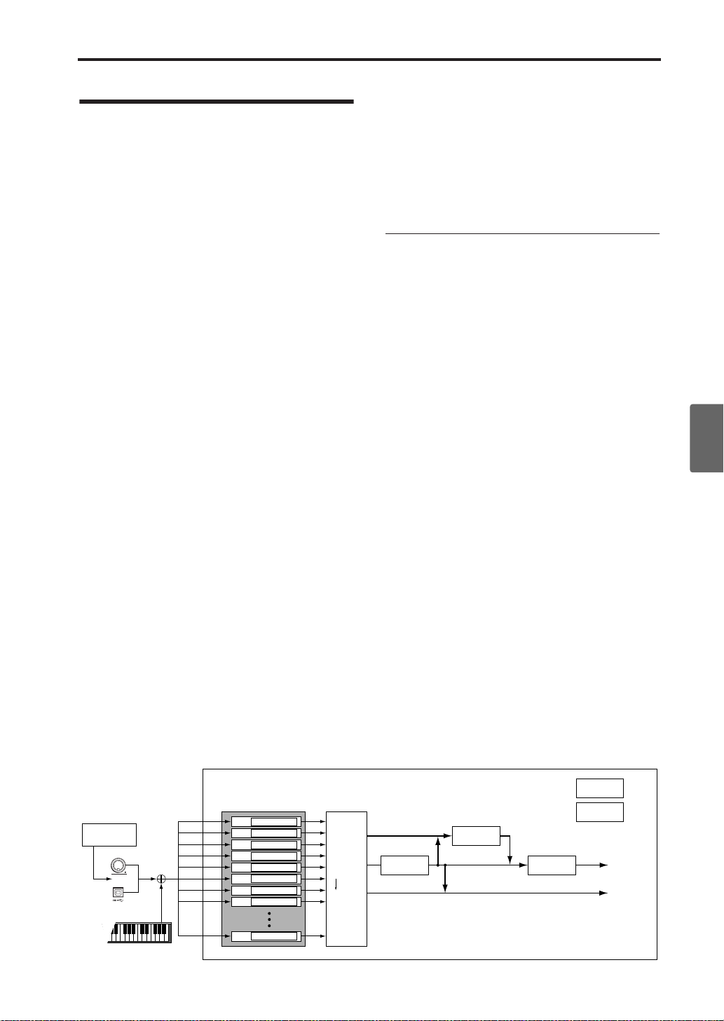
What you can do in Multi mode
What you can do in Multi
mode
A multi set has sixteen tracks. Each track consists
of one program, and parameters such as keyboard
zone, velocity zone, mixer settings, MIDI channel,
and filter settings.
See the illustration “Multi set structure and corresponding pages.”
Multi mode has the following major functions.
• There are 128 multi sets. Each set lets you
assign a program to each of the sixteen tracks,
and you can combine these programs as splits
and layers just as in a combination.
• Each multi set lets you make settings for one
stereo insert effect, two master effects, and a
stereo master EQ.
•You can use two arpeggiators, and you can syn-
chronize them to your MIDI sequencer.
• By setting the “Status” of a track to INT or
BTH, you can play the microX from your external MIDI sequencer as a multi-track sound
module. (☞PG p.55 “Multi Mode”)
• By setting the “Status” of a track to BTH, EXT,
or EXT , you can play an external sound module
on the MIDI channel of the “Control Track.”
(☞PG p.56 “Multi Mode”)
•You can control the program parameters of a
track in realtime using AMS (Alternate Modulation) or control changes. You can also use the
MIDI Sync. function to synchronize the LFO
speed to the tempo.
•You can use the Dmod (Dynamic Modulation)
function to control effect parameters in realtime. You can also use MIDI Sync. to synchronize the LFO speed or delay time to the tempo.
•You can assign a name to the multi set and to
each track.
•You can copy the settings of a combination to a
multi set.
• The “PLAY/MUTE” setting lets you quickly
mute or un-mute a desired track.
• The Tone Adjust function lets you make
detailed adjustments to the program used by
each track.
Overview of Multi set parameters
Select a program for each track
In the MULTI 0: Play, Program page, select a program for each track.
Status and MIDI settings
In the MULTI 2: Track Param, MIDI page, set “Status” to INT for the tracks that you want to play,
and set their MIDI channel to the global MIDI
channel.
Adjust the programs so that they fit
within the multi set
For each track program, specify the poly/mono
setting and adjust timbre parameters such as portamento and transpose.
Layer, split, and velocity switch
In the MUL TI 5: Key Zone, Key page and the 6: Vel
Zone, Vel page, specify the range (layer, split,
velocity switching, etc.) in which each program
will sound.
Effects
The output of each track can be sent to the insert
effect, the master effects, and the master EQ. You
can use the mixer section to freely specify how the
audio signals will be routed.
Quick StartIntroductionSetupProgram
Combination
MultiEffectGlobalArpeggiatorDrum Kit
Multi set structure and corresponding pages
Track 1
External MIDI
sequencer
MIDI IN
USB
MIDI Ch
The microX’s keyboard
Control Track
Track 2
Track 3
Track 4
Track 5
Track 6
Track 7
Track 8
Track 16
Setting parameters
Setting parameters
Setting parameters
Setting parameters
Setting parameters
Setting parameters
Setting parameters
Setting parameters
Setting parameters
BUS : 8–1, 2
Track
Insert Effect
Master Effect
Individual Outputs
Controller Setup : 7–5
Arpeggiator: 7–1…5
(A, B)
Master Effect 1, 2 :
9–1...3
Insert Effect :
8–3, 4
1–1, 9–4, etc. indicate the microX on-screen pages and tabs.
MasterEQ : 9–4
AUDIO OUTPUT
L/MONO, R
AUDIO OUTPUT
INDIVIDUAL 1,2
External control
Other functions
Appendices
73
Page 80

Using and Editing Multi sets
There is one insert effect and two master effects,
and for each of these you can choose one of 89
effect types. The master EQ is a stereo three-band
EQ.
The effect settings created and saved with a program in Program mode are not used in Multi
mode. Effect settings are made independently for
the Multi set.
Arpeggiator
A multi set can use two arpeggiators (dual polyphonic arpeggiators). You can select the arpeggio
pattern, specify the range in which the arpeggio is
generated, and specify the region of notes (keys)
or velocities that will trigger the arpeggiator.
Overview of editing pages
The following pages let you edit a multi set in
detail.
•Select a multi set and play the microX’s
keyboard.
0: Play
1: Tone Adjust • Use Tone Adjust to adjust parameters.
2: T rack Param
3: MIDI Filter1
4: MIDI Filter2
5: Key Zone
6: Vel Zone • Velocity zone settings for each track.
7: Arp/Ctrls
8: InsertFX
9: MasterFX
For details on how to access each mode, page, and
the utility commands, and how to edit values, see
“Basic operations” (☞p.19).
•Receive and play performance data from
an external MIDI sequencer.
•Select a program for each track, and
specify its pan and level.
•Select an external control set.
• MIDI, OSC, Pitch, Delay, and Scale settings
for each timbre.
• MIDI message transmission/reception
filter settings for each track.
•Key zone settings for each track.
•Arpeggiator settings.
•Controller settings.
•BUS and master effect send level settings
for each track.
• Insert Effect routing, selection, and
settings.
•Master Effect selection and settings.
•Master EQ settings.
Comparing (original and edited
sounds)
When you’re in the process of editing a sound,
pressing the [COMPARE] button will recall the
saved version of the sound, as it was before you
started editing. To indicate that you are listening
to the saved version, the button’s LED will light
up.
Pressing [COMPARE] button again returns you to
the version you are editing, and the LED will go
out again.
If you edit while the COMPARE LED is lit, the
button will again go dark and your previous edits
will be lost.
Using Controllers
Just as in other mode, you can use controllers such
as the joystick, OCTAVE [†][π] buttons, and
REALTIME CONTROLS [1]–[4] to add a broad
range of expression to your playing in Combination mode.
These controls let you modify the tone, pitch, volume, effects, etc. in realtime while you play.
REALTIME CONTROLS [1], [2], [3], and [4] will
also function as external controls.
Altering Programs to fit
within a Multi set
You can make adjustments to the sound of the program for each track, for example by changing the
way it plays or by adjusting its pitch or scale.
You can make various changes to Programs within
the context of a particular Multi set, to make them
fit better with other Programs, or to create particular sonic effects. These changes do not affect the
original Programs, or how those Programs sound
in other Multi sets. It is the same as for a Combination. For more details, see “Altering Programs to
fit within a Combination” (☞p.66).
74
Page 81

Layers, Splits, and Velocity Switches
You can use keyboard regions and velocity to
switch between different tracks in a combination,
just as you can in a combination. For more details,
see “Layers, Splits, and Velocity switches”
(☞p.64).
Effects
Effects are covered in their own section of the
manuals, so we won’t go into too much detail
here. (☞p.79)
Insert Effect
You can make settings for the insert effect in the
MULTI 8: InsertFX page.
The output of each track can be sent to the insert
effect. You can use any type of effects, from distortions and compressors to choruses and reverbs.
The Insert Effect can be routed to the main outputs, or to any of the individual outputs. (☞p.84)
Master Effects
You can make master effect settings in the MULTI
9: MasterFX page.
There are two Master Effects, which are accessed
through Sends 1 and 2. These are best-suited to
effects such as reverbs and delays, but you can use
them with any type of effect. (☞p.85)
Master EQ
You can make master EQ settings in the MULTI 9:
MasterFX page.
The master EQ is located immediately before the
(MAIN OUTPUT) L/MONO and R outputs. Use it
to adjust the overall tone. (☞p.85)
Layers, Splits, and Velocity Switches
Saving your edits
Once you’ve tweaked the sound to perfection,
you’ll want to save your work. To save your edits:
1. Press the [UTILITY] button to access the utility
menu.
2. Use the ClickPoint to select “Write Multi,” and
then press the ClickPoint center.
The Write Multi dialog box will appear.
Note: If the display indicates “Memory
Protected,” the multi set memory protect is
turned on. Go to GLOBAL 0: System,
Preference page, and uncheck the Memory
Protect “Multi” setting. (☞p.88)
3. Optionally, you can also select a new location,
or change the Multi set’s name or category.
• If you want to change the name, use the ClickPoint to select the text button ( ) and then
press the ClickPoint center to open the text edit
dialog box.
You can give the Multi set a descriptive name
using the on-screen keyboard. (☞p.114)
After entering the name, press [MENU/OK]
button.
The text edit window will disappear, returning
you to the main Write dialog.
4. In the Write Multi dialog box, press the
[MENU/OK] button to write (save) the
program.
5. A message will ask you for confirmation. If you
are sure you want to write the program, press
the [MENU/OK] button once again.
The multi will be written (saved).
Control via MIDI
Multi mode enables the microX to function as a
MIDI tone generator that is controlled from the
connected computer to play ensemble music consisting of multiple instrument parts. This mode
also permits you to use the microX as a GM tone
generator.
Parameters and performance data
A multi set consists of tracks 1–16, parameters
such as the multi set name, effect and arpeggiator
parameters, and a tempo setting.
75
Quick StartIntroductionSetupProgram
Combination
MultiEffectGlobalArpeggiatorDrum Kit
External control
Other functions
Appendices
Page 82

Using and Editing Multi sets
You can store 128 of these multi sets in the microX.
Tracks 1–16 consist of the following “setting
parameters,” and will transmit and receive the
“performance data” listed below.
MIDI tracks 1–16
Setup parameters
Bank/Program No.*, Pan*, Volume*, Status, MIDI
Channel, Bank Select (When Status=EX2), Force
OSC Mode, OSC Select, Portamento*, Transpose**,
Detune**, Bend Range**, OSC On/Off Ctrl, Delay,
Use Program's Scale, MIDI Filter, Key Zone, Velocity Zone, Track Name, IFX/Indiv.Out BUS Select,
Send1(MFX1)*, Send2(MFX2)*
Performance data
Note On/Off
Program Change (including Bank Select)
Pitch Bend
After Touch (Poly After)
Control Change
Exclusive Message
Tempo*
* You can record tempo as performance data by
adjusting it while you realtime-record onto an
external MIDI sequencer. By receiving this data,
you can change the setting of the multi set during
the playback.
** You can use performance data (MIDI RPN data)
to change the settings of a multi set during playback.
Other parameters: By editing the settings during
realtime recording, you can record the corresponding MIDI exclusive messages as performance data on your external MIDI sequencer . This
gives you a way to change the settings of the multi
set during playback. (GLOBAL 1: MIDI, MIDI Filter “Exclusive” must be checked.)
• For details on Control Change messages and
RPN (☞PG p.172, 175).
• For details on MIDI System Exclusive messages
(☞PG p.176).
Default Settings in Multi Mode
The following table shows the default settings for
Multi mode that are automatically selected, when
GM Initialize is executed, or when the microX
receives a GM ON messages (F0 7E 7F 09 01 F7).
Parameter Track1–9, 11–16 Track10
0 Program Select G001: Acoustic Piano g001: (d): STANDARD Kit
Pan C064 C064
Volume 100 100
2 Status – – The setting remains unchanged
Use Program’s Scale – – The setting remains unchanged
7 Arpeggiator Assign – – The setting remains unchanged
Other Arpeggiator parameters – – The setting remains unchanged
8 IFX/Indiv.Out BUS Select L/R DKit
Send1(MFX1) 0 0
Send2(MFX2) 40 40
IFX – – The setting remains unchanged
Pan(CC#8) – – The setting remains unchanged
BUS Select – – The setting remains unchanged
Send1 – – The setting remains unchanged
Send2 – – The setting remains unchanged
Other Insert Effect parameters – – The setting remains unchanged
9 MFX1 – – 16: St. Chorus
MFX2 – – 53: Rev Smth. Hall
Return1 – – 127
Return2 – – 050
Other Master Effect and Master EQ parameters – – Default settings
76
Page 83

Control via MIDI
Selecting a multi set
You can switch multi sets via MIDI by sending
MIDI Song Select messages. A song select message
will be transmitted when you switch multi sets.
Conversely, you can switch multi sets by receiving
a song select message from the source you specify.
If the Global “Multi Mode” is set to “for Master,”
switching the multi set number will cause each
track with a “Status” of EXT, EX2 or BTH to transmit bank select, program change, volume, pan,
portamento, send 1 and 2, post-IFX pan, and postIFX send 1 and 2 messages on the channel specified for that track.
Switching the program assigned to a
track via MIDI
• Receiving MIDI program change messages to
select programs: (☞p.39 “Using MIDI program
change messages to select programs”)
Note: In order to select programs via MIDI
program changes, the track’s “Status” must be
set to INT.
The MIDI channel of a track is specified by MULTI
2: Track Param, MIDI “MIDI Channel.” When a
program change is received on a MIDI channel
that matches the channel setting of a track, the
program will change if the “Status” of that track is
INT. However, program changes for a track will
also depend on the “Program Change” setting.
The “Status” setting is located in the MULTI 2:
Track Param, MIDI page, and the “Program
Change” setting is in the MUL TI 3: MIDI Filter1, -1
page.
If you’ve installed the included “microX Plug-In
Editor” control plug-in into your DAW software,
you can conveniently select the microX programs
from a list within your DAW. For more details, see
“Editor/Plug-In Editor Manual” (PDF).
MIDI control from the microX’s controllers
If the “Status” is INT or BTH, playing the keyboard or operating the controllers on the “Control
Track” will play/control the microX’s tone generator with the settings (program, level, etc.) of the
selected track, and any other track set to the same
MIDI channel will also sound at this time. If the
“Status” is EXT, EX2, or BTH, these messages will
be transmitted on the MIDI channel specified for
that track.
For more about the MIDI messages transmitted
when you operate the microX’s controllers, and
the AMS (Alternate Modulation Sour ce) and DMS
(Dynamic Modulation Source) that correspond to
each MIDI message, see “MIDI transmission when
the X50/microX’s controllers are operated” (☞PG
p.166).
Other MIDI control
For details on how the microX operates when
transmitting or received control change messages,
see “MIDI transmission when the X50/microX’s
controllers are operated” (☞PG p.166). For more
about MIDI in general, see “MIDI applications”
(☞PG p.171).
Quick StartIntroductionSetupProgram
Combination
MultiEffectGlobalArpeggiatorDrum Kit
77
External control
Other functions
Appendices
Page 84

Using and Editing Multi sets
78
Page 85

Effects settings
Quick StartIntroductionSetupProgram
The effect section of the microX provides one
insert effect, two master effects, one master EQ
(stereo 3-band EQ), and a mixer that controls the
routing of these components.
Effects in each mode
Program mode
In Program mode, the insert effect can be used as
part of the sound-creating process, in the same
way that the output sound of the oscillator (OSC)
is processed by the filter and amp to create the
final sound. Then the master effects can be used to
apply spatial-type effects such as reverb. The stereo 3-band master EQ located immediately before
the (MAIN OUTPUT) L/MONO and R outputs is
used to make final adjustments in tone. These settings can be made independently for each program.
PROG 8: Ed–InsertFX
• Select the BUS and master effect send level for
the oscillator output.
• Insert Effect routing, selection and settings.
PROG 9: Ed–MasterFX
• Master Effect selection and settings.
• Master EQ settings.
ReturnSend
Master EQ
OUTPUT
L/MONO, R
Oscillator
Filter
Amplifier
Master Effect 1,2
Insert Effect
MULTI 8: InsertFX
• BUS and master effect send level settings for
each track.
• Insert Effect routing, selection and settings.
MULTI 9: MasterFX
• Master Effect selection and settings.
• Master EQ settings.
ReturnSend
Master EQ
OUTPUT
L/MONO, R
Timbre 1 / Track 1
Timbre 2 / Track 2
Timbre 8 / Track 16
Master Effect 1,2
Insert Effect
Effect types
You can choose from 89 types of full-digital ef fects
for each effect. The effects are categorized as follows.
Categories of the 89 effect types
Effect No. Effect types
01–15
16–31
32–40
41–51 Early reflection and delay effects
52–57 Reverb effects
58–89
Filter and dynamics effects, such as EQ and
compressor
Pitch and phase modulation effects, such as
chorus and phaser
Other modulation and pitch-shift effects such
as rotary speaker and pitch shifter
Mono and mono-chain effects in which two
mono effects are connected in series
Combination
MultiEffectGlobalArpeggiatorDrum Kit
Combination mode, Multi mode
In Combination mode, and Multi mode, the
insert effect can be applied to each timbre/track.
The master effects are used to apply overall spatial processing, and the master EQ is used to make
overall adjustments in tone.
These settings are made in Combination mode
independently for each combination, and in Multi
mode for each multi set the entire mode.
COMBI 8: Ed–InsertFX
• BUS and master effect send level settings for
each timbre.
• Insert Effect routing, selection and settings.
COMBI 9: Ed–MasterFX
• Master Effect selection and settings.
• Master EQ settings.
Here we will describe some representative effects
in each category.
Filter and dynamics control effects
Equalizers (07: St.Para.4EQ–08: St.Graphic7EQ)
divide the frequency range into several bands, and
allow you to boost or cut the level of each band.
Normally they are used to correct or compensate
the sound, but they can also be used to simulate
the frequency response that is typical of a particular instrument (such as the resonances of a guitar
or string instrument).
Compressors (02: St.Compressor) compress the
dynamic range of the input signal. Compression
makes the sound punchier and more consistent.
This is particularly effective on guitar, piano, or
drum sounds.
79
External control
Other functions
Appendices
Page 86

Effects settings
Limiters (03: St.Limiter–04: Mltband Limit) limit
the level of the input signal to a maximum level
that you specify.
Exciters (11: St.Exct/Enhcr) give the sound greater
clarity and definition. Enhancers sharpen the outline of the sound, bringing it to the front of the
mix. By using these appropriately, you can bring
out sounds that were unclear or easily lost in the
mix.
Distortion (06: OD/HiGain Wah) distorts the
sound. This simulates the distorted sound that is
typically created on a guitar by making the amplifier distort the sound. It is often used not only on
guitar sounds, but also on rock organ sounds.
Pitch/phase modulation effects
Chorus effects (16: St.Chorus–19: St.Ensemble, 26:
St.BiphaseMod) are an effective way to add spaciousness and thickness to any type of sound.
These are ideally suited for use with electric
pianos, strings, guitars, and so on. In an ensemble,
pitch variations between instruments create a rich,
slightly warbling sound. Essentially, this gives the
impression that a number of musicians are playing
together . The chorus ef fect simulates this. In ster eo
performance, the stereo image is widened, thus
creating a magnificent spatial ambience.
Flanger effects (20: St.Flanger–22: St.Env.Flanger)
add unique characteristics to a sound. Although
similar to chorus, a flanger uses a shorter delay
time and feeds some of the output signal back into
the effect, creating a strong swell. Flangers work
very well on sounds that contain a lot of harmonics, as well as on distorted guitar sounds.
Phasers (23: St.Phaser–25: St.Env.Phaser) cyclically
modulate the phase of the sound. They are similar
to the chorus and flanger effects in that both use
modulation, but the manner in which the tonal
quality changes is different. They are effective
with electric piano, guitars, and synth sounds with
a reasonable sustain.
Early reflection and delay effects
Early reflection effect (41: Early Reflect) produces
only the early reflections of a reverb effect. Using
just these early reflections, you can add weight or
spatial effects to a sound, such as reverberation.
Without the r everberation, you can achieve a clean
effect sound.
Delays (43: LCR Delay–51: Sequence Dly) create
an echo effect by delaying the sound for a fixed
length of time. You can also make the delayed
sound repeat (feed back).
Level
Dry sound
Delay time
Delay sound
Time
Reverb effects
Reverb (52: Rev Hall–57: Rev Brt. Room) is an effect
that creates the spacious reverberation of sounds
played in a hall or room. Reverb simulates the
sounds that are reflected from the ceiling and wall.
When you hear music in a concert hall, the sound
from the instruments and voices reaches your ear
directly, but also reaches your ear after being
reflected off the ceiling and walls (and being
delayed by a corresponding length of time). In this
way, the direct sound (the “dry” sound) is joined
by numerous reflections that cr eate the impression
of a large acoustical space. The way in which the
sound is reflected will depend on the materials of
the ceiling and walls, and also on the size and
shape of the hall. These factors also affect the way
in which the reverberation decays. Different effect
types let you simulate a broad range of reverberation, and you can also edit the parameters to make
detailed changes to the character of the sound.
LevelLevel
Dry sound
Early reflections
Other modulation and pitch shift
effects
Rotary speaker effect (40: Rotary SP) simulates the
rotating speaker effect used in organs. It is ideal
for use with organ sounds, but it will also create a
unique effect with other sounds.
Pitch shifters (38: Pitch Shifter, 39: PitchShift Mod)
shift the pitch of the input signal. You can mix the
pitch-shifted sound with the original sound to create a chorus effect, or create special effects in
which the pitch continues to rise (or fall).
80
Dry sound
Sound
source
Reverb sound
Pre Delay
Time
Effects that combine two mono
effects connected in series
These connect two mono effects in series. They
include a four-band parametric equalizer connected in series with some other effect (e.g.,
exciter, chorus, delay), or a compressor connected
with another effect (of the types listed above).
Page 87

Effect settings for a program
Routing
The structure of the insert effect, master effects,
and master EQ is the same in each mode. However , the r outing will determine how the oscillator
output of the program is sent to the insert effect
and the master effects. As an example, here’s how
to specify the routing and make effect settings in
Program mode.
1. Access the PROG 8: Ed–InsertFX, BUS page.
2. Set “BUS Select (All OSCs)” to specify where
the oscillator output will be sent.
L/R: The output will be sent to (MAIN
OUTPUT) L/MONO and R. (See diagram
below)
Note: After passing through the master EQ, the
sound will be sent to (MAIN OUTPUT) L/
MONO and R.
Effect settings for a program
1, 2, 1/2: The output will be sent to
(INDIVIDUAL OUTPUT) 1 or 2. (See diagram
below)
Note: It will not be sent to the insert effect, the
master effects, or the master EQ.
Off: The sound will not be sent to (MAIN
OUTPUT) L/MONO, R, (INDIVIDUAL
OUTPUT) 1 and 2. After passing through the
master effects, the sound is sent to the MAIN
OUTPUT. Choose this setting if you want to
send the sound in series through the master
effects at the send level specified by “MFX
Send.” (See diagram below)
Quick StartIntroductionSetupProgram
Combination
MultiEffectGlobalArpeggiatorDrum Kit
IFX: The output will be sent to insert effect IFX.
(See diagram below)
BUS Select (All OSCs) = L/R
IFX / Indiv.Out
BUS Select
OSC 1
OSC 2
Pan
BUS Select
= L/R
Select from:
L/R
IFX
1
2
1/2
Off
BUS Select (All OSCs) = IFX
IFX / Indiv.Out
BUS Select
OSC 1
OSC 2
Pan
BUS Select
= IFX
Select from:
L/R
IFX
1
2
1/2
Off
IFX BUS
mono x 2
IFX BUS
mono x 2
stereo
stereo
PROG 8: Insert FX
Insert Effect
IFX
PROG 8: Insert FX
Insert Effect
IFX
Post IFX
Pan(CC#8)
Post IFX
Pan(CC#8)
BUS Select
BUS Select
= L/R
Select from:
L/R
1
2
1/2
Off
BUS Select
BUS Select
= L/R
Select from:
L/R
1
2
1/2
Off
Post IFX
Send1 / 2
mono x2
Post IFX
Send1 / 2
mono x2
Send1
Send1
mono
mono
Send2
Send2
mono
mono
Chain
Chain
Master Effects
MFX1
MFX2
Master Effects
MFX1
MFX2
PROG 9: Master FX
L/R BUS
stereo
Return1 / 2
stereo
stereo
PROG 9: Master FX
L/R BUS
stereo
Return1 / 2
stereo
stereo
Master EQ
Master EQ
AUDIO OUTPUT
(MAIN) L/MONO, R
AUDIO OUTPUT
(INDIVIDUAL)1/2
AUDIO OUTPUT
(MAIN) L/MONO, R
AUDIO OUTPUT
(INDIVIDUAL)1/2
External control
Other functions
Appendices
81
Page 88

Effects settings
BUS Select (All OSCs) = 1/2
IFX / Indiv.Out
BUS Select
OSC 1
OSC 2
Pan
BUS Select
= 1/2
Select from:
L/R
IFX
1
2
1/2
Off
BUS Select (All OSCs) = Off
IFX / Indiv.Out
BUS Select
OSC 1
OSC 2
Pan
BUS Select
= Off
Select from:
L/R
IFX
1
2
1/2
Off
mono x 2
mono x 2
IFX BUS
IFX BUS
stereo
stereo
PROG 8: Insert FX
Insert Effect
IFX
PROG 8: Insert FX
Insert Effect
IFX
Post IFX
Pan(CC#8)
Post IFX
Pan(CC#8)
BUS Select
BUS Select
= L/R
Select from:
L/R
1
2
1/2
Off
BUS Select
BUS Select
= L/R
Select from:
L/R
1
2
1/2
Off
Post IFX
Send1 / 2
mono x2
Post IFX
Send1 / 2
mono x2
Send1
Send1
mono
mono
Send2
Send2
mono
mono
Chain
Chain
Master Effects
MFX1
MFX2
Master Effects
MFX1
MFX2
PROG 9: Master FX
L/R BUS
stereo
Return1 / 2
stereo
stereo
PROG 9: Master FX
L/R BUS
stereo
Return1 / 2
stereo
stereo
Master EQ
Master EQ
AUDIO OUTPUT
(MAIN) L/MONO, R
AUDIO OUTPUT
(INDIVIDUAL)1/2
AUDIO OUTPUT
(MAIN) L/MONO, R
AUDIO OUTPUT
(INDIVIDUAL)1/2
3. “MFX Send” specifies the send level from each
oscillator to the master effects.
This is valid only if “BUS Select (All OSCs)” is
set to L/R or Off.
If IFX is selected for “BUS Select (All OSCs),”
the send level to the master effects is adjusted
by the “Send 1 (MFX1)” and “Send 2 (MFX2)”
parameters (PROG 8: Ed–InsertFX, Setup page)
after the signal has passed through the insert
effect.
Selecting an insert effect, and routing after the insert effect
1. Access the PROG 8: Ed–InsertFX, Setup page.
The Setup page displays the state of the routing
and the insert effect settings. In this page you
can also make “BUS Select” settings. Use the
ClickPoint to choose (All OSCs), and use the
[VALUE] dial etc. to make a selection.
BUS SelectInsert Effect
IFX On/Off Send1(MFX1)
Pan (CC#8)
Send2(MFX2)
2. In “Insert Effect,” select the desired insert
effect.
You can press the [CATEGORY] button and
choose an effect from six categories.
3. In “IFX On/Off,” turn the insert effect on/off.
If this is set to Off, the result will be the same as
if 00: No Effect is selected. The input sound
will be output without change.
Note: You can use the Utility “Copy Insert
Effect” to copy effect settings from another
program, etc.
4. Set the “Pan (CC#8),” “BUS Select,” “S1 (Send1
(MFX1)),” and “S2 (Send2 (MFX2))” parameters
that follow the insert effect.
“Pan (CC#8)”: Set the pan. This is valid only if
“BUS Select” is set to L/R.
“BUS Select”: Specify the output destination.
Normally you will set this to L/R. If you want
to output the sound from (INDIVIDUAL
OUTPUT) 1 and/or 2, set this to 1, 2, or 1/2.
“Send1 (MFX1),” “Send2 (MFX2)”: Set the
send level to the master effects. For this
example, set these to 127.
82
BUS Select
IFX On Insert Effect
Page 89

Effect settings for a program
5. Move to the IFX page, and set the parameters of
the effect that you selected for the insert effect.
For details on the parameters of each effect, see PG
p.104–.
Selecting master effects, and chain
settings
The input level of the master effect is determined
by the send level 1 and 2 settings (routing step 3,
or insert effect step 4). If send levels 1 and 2 are 0,
no master effects will be applied. Send level 1 is
for MFX1, and send level 2 is for MFX2.
1. Access the PROG 9: Ed–MasterFX, Setup page.
MFX1 On/Off
MFX Chain
Chain Direction Chain Level
2. In “Master Effect 1” and “Master Effect 2,”
select the type of each master effect.
You can press the [CATEGORY] button and
choose an effect from six categories.
Note: The input/output of the master effect is
mono-in/stereo-out. Even if you select a stereoinput type effect, the input will be monaural.
3. In “MFX1 On/Off” and “MFX2 On/Off,”
switch each master effect on/off.
If this is Off, the output of the master effect
will be muted.
4. In “Return 1” and “Return 2,” adjust the output
level of each master effect.
For each effect, the W value of “W/D” (Wet/
Dry) is the effect output level. This is
multiplied by the return value (“Rtn”=127 is
x1.0) to determine the actual master effect
output level.
5. Specify the routing of master effects 1 and 2.
If the “MFX Chain” check box is checked,
MFX1 and MFX2 will be connected in series.
The settings described below are valid if this
check box is checked.
Chain Signal
Return1Master Effect 1
Return2Master Effect 2MFX2 On/Off
Master EQ
“Chain Direction” specifies the direction in
which MFX1 and MFX2 will be connected.
“Chain Signal” specifies whether the signal
sent from one master effect to the other will be
stereo, or only L or R.
“Chain Level” specifies the level at which the
signal is sent from one master effect to the other
master effect.
Return1 / 2
Return1 / 2
Chain
Level
Return1 / 2
Chain
Level
stereo
stereo
stereo
stereo
stereo
stereo
stereo
stereo
stereo
L/R BUS
L/R BUS
L/R BUS
Master EQ
Master EQ
Master EQ
AUDIO OUTPUT
(MAIN) L/MONO, R
AUDIO OUTPUT
(MAIN) L/MONO, R
AUDIO OUTPUT
(MAIN) L/MONO, R
Send1
mono
Send1
mono
Chain Signal
=LR Mix,
L Only,
R Only
Send1
mono
Chain Signal
=LR Mix,
L Only,
R Only
Send2
MFX Chain
=Off
mono
Send2
MFX Chain
=On
mono
Send2
MFX Chain
=On
mono
Master
Effects
MFX1
MFX2
Master
Effects
MFX1
MFX2
Chain Direction
=MFX1→MFX2
Master
Effects
MFX1
MFX2
Chain Direction
=MFX2→MFX1
6. Move to the MFX1 or MFX2 page, and set the
parameters of the effect that you selected as the
master effect.
For details on the parameters of each effect, see PG
p.104–.
Master EQ
1. Use the stereo 3-band master EQ to make final
equalizing adjustments immediately before the
sound is output from the (MAIN OUTPUT) L/
MONO and R jacks.
Set the Low , Mid, and High gain in the PROG 9:
Ed–MasterFX, Setup page. Low and High are
shelving-type, and Mid is a peaking-type
adjustment. These settings are linked with the
Low, Mid, and High “Gain” settings of the
Master EQ page. In addition to these settings,
the Master EQ page also lets you specify the
center frequency and bandwidth (Mid only) of
each band, and make settings for dynamic
modulation.
Quick StartIntroductionSetupProgram
Combination
MultiEffectGlobalArpeggiatorDrum Kit
External control
Other functions
83
Appendices
Page 90

Effects settings
Effect settings in combination, and Multi
Routing
In Combination and Multi modes, you can specify
the routing of each timbre/track to the insert ef fect
and master effects. These settings are made in the
same way in each of these modes. W e will be using
the example of Combination mode in our explanation here.
1. Access the COMBI 8: Ed–InsertFX, BUS page.
2. In “BUS Select,” specify where the output of
each timbre will be sent. (See diagram below)
L/R: The output will be sent to (MAIN
OUTPUT) L/MONO and R.
Note: After passing through the master EQ, the
sound will be sent to (MAIN OUTPUT) L/
MONO and R.
IFX: The output will be sent to insert effect IFX.
1, 2, 1/2: The output will be sent to
(INDIVIDUAL OUTPUT) 1 or 2.
Note: It will not be sent to the insert effect, the
master effects, or the master EQ.
Off: The sound will not be sent to (MAIN
OUTPUT) L/MONO, R, (INDIVIDUAL
OUTPUT) 1 and 2. After passing through the
master effects, the sound is sent to the MAIN
OUTPUT. Choose this setting if you want to
send the sound in series through the master
effects at the send level specified by “MFX
Send.” (See diagram below)
3. “S1” (Send1(MFX1)), “S2” (Send2(MFX2))
specifies the send level from each timbre to the
master effects.
This can be set only if “BUS Select” is set to L/R
or Off.
The actual send level will be the send level of
each timbre multiplied by the send level of each
oscillator of the program selected for the
timbre. If the send level of a program is 0, the
actual level will be zero even if the send level
setting is raised here.
If IFX is selected for “BUS Select,” set the send
levels to the master effects by adjusting the “S1
(Send1(MFX1))” and “S2 (Send2(MFX2))”
parameters (COMBI 8: Ed–InsertFX, Setup
page) located after the signal has passed
through the insert effect.
Selecting an insert effect, and routing after the insert effect
BUS SelectInsert Effect
IFX On/Off Send1(MFX1)
Routing
Pan (CC#8)
The Setup page displays the state of the routing
and insert effect settings.
Send2(MFX2)
IFX On Insert Effect
Timbre / Track 1
Timbre / Track 2
Timbre / Track 3
Timbre / Track 4
Timbre / Track 8
84
Track 16
Pan
IFX / Indiv.Out
BUS Select
BUS Select
= L/R
BUS Select
= IFX
BUS Select
= 1
BUS Select
= Off
BUS Select
= 1/2
BUS Select
= 2
Select from:
(DKIT)
L/R
IFX
1
2
1/2
Off
IFX BUS
stereo
COMBI/MULTI 8: Insert Effect
Insert Effect
IFX
Post IFX
Pan(CC#8)
BUS Select
BUS Select
= L/R
Select from:
L/R
1
2
1/2
Off
Post IFX
Send1 / 2
COMBI/MULTI 9: Master Effect
Return1 / 2
stereo
stereo
stereo
L/R BUS
Master EQ
AUDIO OUTPUT
(MAIN) L/MONO, R
AUDIO OUTPUT
(INDIVIDUAL)1/2
Send2
Send1
Master Effects
Chain
mono
MFX1
MFX2
mono
mono x 2mono x 2
Page 91

Dynamic modulation and BPM/MIDI Sync.
In this example, IFX is used by 2 (timbre 2) and 5
(timbre 5).
In the same way as for a program, you can select
the insert effect, turn it on/off, and set the “Pan
(CC#8),” “BUS Select,” “S1” (Send 1 (MFX1)), and
“S2” (Send2 (MFX2)) parameters that follow the
insert effect. (☞p.82)
Master effects
Master EQ
These settings are made in the same way as for
programs (☞p.83).
Specifying the MIDI channel that will
control effects
Insert effect
You can specify the MIDI channel that will control
the insert effect dynamic modulation (Dmod) and
the “Pan” (CC#8), “Send 1 (MFX1),” and “Send 2
(MFX2)” settings that follow the insert effect.
An asterisk “
for the channel numbers of timbres that are r outed
to IFX. If multiple timbres/tracks of different
MIDI channels are routed to IFX, set the “Control
Channel” to specify the channel you’ll use to control the effect.
For a combination, you will normally use the Gch
(global MIDI channel) to control the effect.
For a multi set, you can use any MIDI channel that
is convenient.
“All Rt.” stands for All Routed, indicating that
you can control the effect using the channel of any
timbre/track that is routed.
Master effects
You can specify the MIDI channel that will control
dynamic modulation (Dmod) for the master effects.
For a combination, you will normally use the Gch
(global MIDI channel) to control the effects.
For a multi set, you can use any MIDI channel that
is convenient.
” is shown at the right of Ch01–16
*
Dynamic modulation and
BPM/MIDI Sync.
Dynamic modulation (Dmod) is a function that lets
you use MIDI messages or the microX’s controllers
to control specific effect parameters in realtime.
BPM/MIDI Sync. is another function that controls
effect parameters, and is used to synchronize the
LFO speed of modulation-type effects or the delay
time etc. of delay-type effects to the tempo of the
arpeggiator or an external sequencer.
Using dynamic modulation to control effects in realtime
These examples show how you can use dynamic
modulation to control an effect parameter in realtime.
1. As described in the procedure for “Effect
settings for a program” (☞p.81), set “IFX” to
49: LCR BPM Delay. Verify that a delay sound
is being output.
Then continue on to set the items described
below.
Moving the joystick to vary the delay
level via Dmod
1. Access the PROG 8: Ed–InsertFX, IFX page.
2. Set “InLvl Mod” to +100.
3. Set “Src” to JS+Y#1.
The joystick will control the input level to the
effect.
When you set “Src” to JS+Y#1, the level of
delayed signal will be set to zero, and will
gradually increase as you push up on the
joystick.
Quick StartIntroductionSetupProgram
Combination
MultiEffectGlobalArpeggiatorDrum Kit
External control
Pressing a foot switch to vary the feedback level via Dmod
1. In the GLOBAL 0: System, Foot page, set “Foot
SW Assign” to Foot SW (CC#82).
85
Other functions
Appendices
Page 92

Effects settings
2. Return to the PROG 8: Ed–InsertFX, IFX page,
and set the C Fb (C Delay Feedback) “(Source)”
to SW1 #82.
3. Set “(Amount)” to +30.
time will change in synchronization to any
changes you make in the arpeggiator tempo.
If you rotate the REALTIME CONTROLS
knob [4] to change the tempo while the delay
is sounding, noise may occur in the delay
sound. This is because the delay sound
becomes discontinuous, and is not a
malfunction.
For some effects, you can synchronize the
LFO frequency to the tempo. Set the effect
parameters “BPM/MIDI Sync” to On, and
“BPM” to MIDI. For details see PG p.160.
4. (Move the joystick up.) Press the foot-switch;
the feedback level will increase, and the delay
sound will continue for an extended time.
The “(Amount)” setting determines the
feedback level when the foot-switch is pressed.
If you set “(Amount)” to –10 and press the footswitch, the feedback level will be 0.
Using the BPM/MIDI Sync. function
to synchronize the delay time to
arpeggiator tempo changes.
The BPM/MIDI Sync. function lets you synchronize the delay time to the tempo of the arpeggio.
1. In the PROG 8: Ed–InsertFX, IFX page, set
“BPM” to MIDI.
2. For L, C, and R, set “L/C/R Bs” and “T imes” as
desired.
For this example, set “L/C/R Bs” to and
“Times” to 1 so that the effect will be easily
understandable. The delay time will repeat at
an interval of a 8th note.
Saving edited effect settings
Effect parameters that you edit in Program mode
are saved when you write the program. Similarly,
effect parameters that you edit in Combination
mode or Multi mode are saved when you write
the combination or multi set. (☞p.45, 61, 75)
Bypassing the insert effect or the master effects
Normally, you will switch the effects on/off individually for each program, combination, or multi
set. However, you also have the option of bypassing the insert effect or master effects for the entire
microX if you don’t want to use them.
For example, this can be useful when you’re using
an outboard effect such as reverb, chorus, or compressor to create an effect that you would otherwise create using the microX’s master effects, or
when you’re using a plug-in effect on your computer to process the sound of the microX together
with other sound sources.
1. Press the [GLOBAL] button to enter Global
mode.
2. Access the GLOBAL 0: System, Basic page.
3. Set the realtime controller function to C-mode,
and rotate REALTIME CONTROLS knob [4]
(“TEMPO”).
(Move the joystick up.) Operate the knob; the
delay time will change.
4. Turn on the [ARP ON/OFF] button to start the
arpeggiator.
Select an arpeggio pattern as desired.
(Move the joystick up.) When you rotate
REALTIME CONTROLS knob [4], the delay
86
3. Check the “IFX Off” check box if you want to
bypass the insert effect.
Check the “MFX1 Off” dialog box if you want
to bypass master effect 1, or the “MFX2 Off”
dialog box if you want to bypass master effect
2.
Page 93

Global Mode
Quick StartIntroductionSetupProgram
How Global mode is structured
In Global mode you can make overall settings that
apply to the entire microX, such as master tuning,
key transpose, effect global switch, global MIDI
channel, and system clock.
In addition, you can create user drum kits, arpeggiator, and scales, make settings for the damper
pedal and assignable foot switches/pedals, and
specify category names for programs and combinations.
Global mode page structure
0: System
1: MIDI
2: User Scale
3: Category Name
4: DKit • Edit drum kits
5: Arp.Pattern • Edit user arpeggio patterns.
6: Ext Control
For details on how to access each page, tab or utility command, and how to edit the values, see
“Basic operations” (☞p.19).
The edits you perform in Global mode will be
preserved until you turn off the power is
turned off, but will be lost when the power is
turned off. Four types of data are handled in
Global mode: user drumkit settings (GLOBAL
4), arpeggiator settings (GLOBAL 5), external
control settings (GLOBAL 6), and all other
global settings (GLOBAL 0–3). You into its
own memory area.
Note that Compare can’t be used in Global
mode.
•Basic settings for the entire microX
•Controller settings for the pedals etc.
connected to the rear panel
• MIDI-related settings for the entire
microX
•User registered scale settings.
Specify 16 octave scales, and one allnote scale.
•Edit category names for programs and
combinations
•External control settings.
Assign CC# to REALTIME CONTROLS
knobs
System setup 0: System
Basic Page
Tuning to another instrument/Transposing
“Master Tune” adjusts the overall pitch. Edit this
setting when you are playing the microX with
other instruments, or when playing along with
music on CD or tape. You can adjust the pitch in a
range of ±50 cents (one semitone = 100 cents). If
this is at 0, middle A is tuned to 440 Hz.
“Key T ranspose” shifts the pitch in semitone steps.
Edit this setting when you want to transpose the
sound of the entire microX. You can adjust the
transposition in a range of ±1 octave.
Adjusting the way in which velocity
will affect the volume or tone
You can adjust the way in which changes in velocity will affect the volume or tone by selecting different velocity curves. Each curve has its own
character , so you can select the curve that is appropriate for your own playing dynamics, playing
style, and the effect that you wish to obtain. (☞PG
p.76)
“Velocity Curve” selects the velocity curve.
Bypassing the effects
If the FX SW “IFX Off,” “MFX1 Off,” and “MFX2
Off” boxes are checked, the insert effect, master
effect 1, and master effect 2 will respectively be
bypassed. This applies to the entire microX
regardless of the mode. For example, if you’ve
connected the microX’s outputs to an external
mixer and are using an external effect pr ocessor to
apply reverb or chorus to the sound, you can turn
off the microX’s master effects.
Combination
MultiEffectGlobalArpeggiatorDrum Kit
External control
Other functions
87
Appendices
Page 94

Global Mode
Linking the arpeggiator to programs
and combinations
You can specify whether the arpeggiator settings
written to a program or combination will also be
selected when you select that program or combination, or whether the arpeggiator settings will
remain in their current state when you switch the
program or combination.
When the microX is shipped from the factory, the
former setting is selected. You can use the latter
setting if you want to use the same arpeggiator
settings to generate phrases and patterns while
you select and try out different programs and
combinations.
If the Auto Arp. “Program” or “Combination”
boxes are checked, selecting a program or combination respectively will also select the arpeggiator
settings that are written in that program or combination.
OCTAVE
When you switch programs, combinations, or
multi sets, you have the option of also recalling
the OCT AVE [†][π] button setting that is written
as part of this data.
If the “OCTAVE Keys [†/π]: Use Prog/Combi/
Multi’s Octave” box is checked, the OCTAVE
[†][π] button setting written in the data will be
recalled when you select the program etc. If this
box is not checked, the OCTAVE [†][π] setting
will not change when you select the program etc.;
the current setting will be maintained until you
switch the octave yourself.
Preference Page
Recalling the last-selected mode and
page at power-on
The state of microX when the power is turned on
will depend on the setting of “Power On Mode”.
If “Power On Mode” is set to Reset (factory setting), microX will automatically select the Combination mode 0: Play.
If “Power On Mode” is set to Memorize, microX
will power on using the same mode and page that
were selected when the power was previously
turned off.
Protecting the memory
If one or more of the “Memory Protect” boxes are
checked, operations such as writing, loading etc.
will be prohibited for the corresponding type of
memory.
If you want to edit and write (save) settings, you’ll
need to uncheck this box. In order to load the preloaded data, you’ll first need to uncheck the Memory Protect box for the data you want to load.
Foot Page
Specifying the function of the
ASSIGNABLE Switch and ASSIGNABLE Pedal
Assignable Switch
Foot SW Assign lets you assign a function to a
footswitch, such as the optional Korg PS-1, connected to the rear-panel ASSIGNABLE SWITCH
jack.
• This is set by “Foot SW Assign.”
You can choose from the following functions:
Alternate modulation source
Effect dynamic modulation source
Switch portamento on/off
Control the sostenuto effect
Turn the soft pedal effect on/off
Arpeggiator on/off
Select programs or combinations (up/down)
Tap tempo
Aftertouch transmission
The functions of controllers such as the joystick
or knobs [1]–[4]. (☞PG p.164)
88
Page 95

MIDI-related settings 1: MIDI
Assignable Pedal
You can specify the function of an assignable
pedal, such as the optional XVP-10 EXP/VEL
pedal or EXP-2 foot controller, connected to the
ASSIGNABLE PEDAL jack.
• This is set by “Foot
You can choose from the following functions:
Master volume
Alternate modulation source
Effect dynamic modulation source
Portamento pitch change speed
Volume
The pan following an insert effect
Pan
Expression
Send levels to the master effects
Aftertouch transmission
Duplicate the function of another controller,
such as the joystick or knobs [1]–[4] (☞PG
p.165)
Note: You can use this as a source for alternate
modulation or effect dynamic modulation, and
use it to control program parameters or effect
parameters. In this case, set “Foot SW Assign” to
Foot SW (CC#82), and “Foot Pedal Assign” to Foot
Pedal (CC#04).
Pedal Assign.”
Creating user scales 2: User Scale
Creating an original scale, and
assigning it to a Program
On the User Scale page, you can create your own
original scales. These include sixteen different
User Octave Scales, in which the pitch of each note
of the octave is repeated for all octaves, and one
User All Note Scale, in which the pitch of each of
the 128 notes can be specified independently.
By adjusting the pitch of each key in the range of
±99 cents, you can raise or lower it by approximately one semitone relative to the normal pitch.
The user scales you create here can be used by
specifying the scale for a program, for each timbre
of a combination, or for each track of a Multi set.
You can choose these scales from the following
pages.
Mode Page
Program 1: Ed–Basic, Program Basic
Combination 2: Ed–TimbreParam, Other
Multi 2: Track Param, Other
Quick StartIntroductionSetupProgram
Combination
MultiEffectGlobalArpeggiatorDrum Kit
MIDI-related settings 1: MIDI
MIDI Setup, MIDI Filter
Here you can make MIDI-related settings for the
entire microX, such as the global MIDI channel
and the MIDI clock setting. You can also use the
utility commands of this page to transmit MIDI
System Exclusive data dumps. (☞PG p.81)
Here’s how to set the scale type for each track in
Multi mode.
1. Create a user octave scale or a user all notes
scale.
Select a key, and use the VALUE controllers to
adjust the pitch. The range of ±99 raises or
lowers the pitch approximately one semitone
above or below the standard pitch.
Note: You can copy one of the preset scales and
edit it to create an original scale. To do so, use
the “Copy Scale” utility.
2. Press the [MULTI] button to enter Multi mode.
3. Press the [MENU/OK] button, choose “Track
Param” from the “PAGE MENU,” and then
press the [PAGE+] button to access the 2: Track
Param, Other page.
External control
Other functions
89
Appendices
Page 96

Global Mode
4. If you want the Track to use the scale saved
with its individual Program, check the track’s
“Use Prog’s Scale” check box.
Tracks that are not checked will use the scale
specified by Scale “Type” (Multi’s Scale).
5. Set “Type” (Multi’s Scale) to select the scale for
the currently selected song.
Setting category names 3: Category Name
Program, Combination Category
The Category Name pages let you assign names to
the Program, and Combination categories. (☞PG
p.86)
Saving the global settings
When you’ve finished editing in the Global mode,
you’ll need to write (save) your settings.
The edits you perform will be lost when the
power is turned off, unless you save them.
1. Select one of the GLOBAL 0: System–3:
Category Name pages.
2. Press the [UTILITY] button to access the utility
menu, and choose “Write Global Setting.”
3. To write (save) your settings, press the
[MENU/OK] button.
A dialog box will ask you to confirm that you
want to write the settings.
4. Press the [MENU/OK] button to write your
settings, or press the [EXIT/CANCEL] button if
you decide not to write.
The global settings will be written (saved).
Drum kit 4: DKit,
Arpeggiator 5: Arp.Pattern,
External Control 6: Ext.Control settings
Here you can make drum kit, arpeggiator, and
external control settings.
See the corresponding page listed below.
☞p.107 “Using Drum Kits”
☞p.91 “Arpeggiator settings”
☞p.111 “External control settings”
90
Page 97

Arpeggiator settings
The arpeggiator is a function that automatically
generates arpeggios (playing the notes of the
chord individually, with a constant tempo). Most
arpeggiators produce an arpeggio when you play
a chord on the keyboard.
The chord you play on
the keyboard is sounded
as an arpeggio
(individual notes)
In addition to this, the microX’s arpeggiator is a
polyphonic arpeggiator that is able to produce a
variety of chordal transformations or phrases
based on the pitch or timing of the notes you play
on the keyboard. These functions let you use the
arpeggiator to play a wide range of patterns
including drum or bass phrases, and guitar or
keyboard backing riffs. It is also effective to use
the arpeggiator as part of the sound-creating process when creating subtly-moving pads, synthsounds, or sound effects.
In Program mode you can use one arpeggiator.
In Combination mode and Multi mode, the
microX features a Dual Polyphonic Arpeggiator
that lets you simultaneously use two arpeggio patterns. You can take advantage of this in many
ways, such as applying separate arpeggio patterns
to a drum program and a bass program, or using
keyboard zones or velocity splits to switch
between two arpeggio patterns.
UP,
DOWN,
ALT1,
ALT2,
RANDOM
U000–250
Preset arpeggio patterns
With the factory settings, this contains a variety
of preloaded user arpeggio patterns. You can
create and write your own user arpeggio
patterns.
Arpeggiator features in Program mode
Using the arpeggiator in Program
mode
1. Press one of the PROGRAM [A]–[GM] buttons.
(The button will light.)
Program mode is selected. (☞p.37 “Selecting
programs”)
As you select various programs, you will notice
that the [ARP ON/OFF] button will light for
some programs. Play the keyboard of the
microX and the arpeggio will start.
For other programs, you can press the [ARP
ON/OFF] button (the button will light) to turn
on the arpeggiator. Arpeggios will begin
sounding when you play the keyboard.
2. As described in the following sections
“Arpeggio controllers” and “Editing arpeggio
settings that appear in the display” (☞p.92),
move the controllers or modify the parameters
to change the way in which the arpeggios are
played.
Arpeggio controllers
Arpeggiator on/off (ARP ON/OFF)
• Each time you press the [ARP ON/OFF] button, the arpeggiator will be switched on/off.
When this is on, the button will light, and
playing the keyboard will start the selected
arpeggio pattern.
[SELECT] button: C[ARP ON/OFF] button
Quick StartIntroductionSetupProgram
Combination
MultiEffectGlobalArpeggiatorDrum Kit
External control
Knobs [1]–[4]
Other functions
Appendices
91
Page 98

Arpeggiator settings
Adjusting the arpeggiator tempo (TEMPO)
1. Press the REALTIME CONTROLS [SELECT]
button to make the right “C” LED light.
2. Rotate the [4] (TEMPO) knob to adjust the
tempo. The “ =” value in the upper right of the
display will change.
You can set this in the range of 40–240. The LED
located above the [ARP ON/OFF] button
blinks at quarter-note intervals of the timing
you specify.
You can also set the timing from within the
display. Use the ClickPoint to select “ =” and
turn the [VALUE] dial to specify the tempo.
The LED will blink at the specified tempo.
Note: You can set the tempo by pressing a
separately sold PS-1 foot switch that is
connected to the PEDAL jack (when “Foot SW
Assign” is set to Tap Tempo).
Note: The arpeggio playback speed is affected
by the “Reso (Resolution)” setting (0: Play, Arp.
Play page, 7: Ed–Arp/Ctrls, Setup page).
If “MIDI Clock” (GLOBAL 1: MIDI) is set to
Ext-MIDI or Ext-USB, or set to Auto and MIDI
clock messages are being received from an
external device, the display will indicate “ =”
EXT. This lets you synchronize the tempo
with an external MIDI device. In this case you
won’t be able to adjust the tempo on the
microX.
Rotating the knob toward the left will make the
notes weaker , and r otating the knob towar d the
right will make the notes stronger. At the center
position (12 o’clock), the velocity will be as
specified by the program parameter “Velocity”
(7: Ed–Arp/Ctrls, Setup page).
Note: You can control the tone effectively by
simultaneously adjusting the REALTIME
CONTROLS A-mode [1] (LPF CUTOFF), [2]
(RESONANCE/HPF), and [3] (EGINTENSITY) knobs.
Changing the length of the arpeggio
pattern (ARP-LENGTH)
1. Press the REALTIME CONTROLS [SELECT]
button to make the right “C” LED light.
2. Turn the [3] (ARP-LENGTH) knob to change
the length of the arpeggio pattern.
At the center position (12 o’clock), the length
will be the same as the arpeggiator’s “Lgth
(Length)” setting (7: Ed–Arp/Ctrls, Setup
page). Turn the knob toward the left to shorten
the pattern, or toward the right to lengthen the
pattern. The arpeggio pattern will play
repeatedly for the number of times specified by
LENGTH. Changing this value will change the
character of the pattern.
Note: This has no effect for the preset patterns
(UP, DOWN, ALT1, ALT2, RANDOM).
Adjusting the length of the arpeggiated
notes (ARP–GATE)
1. Press the REALTIME CONTROLS [SELECT]
button to make the right “C” LED light.
2. Rotate the [1] (ARP-GATE) knob to adjust the
duration of the arpeggiated notes.
Rotating the knob toward the left will shorten
the notes, and rotating it toward the right will
lengthen the notes. At the center position (12
o’clock), the note length will be as specified by
the program parameter “Gate” (7: Ed–Arp/
Ctrls, Setup page).
Note: You can control the effect by
simultaneously adjusting the REALTIME
CONTROLS A-mode [4] (EG-RELEASE) knob.
Adjusting the level of the arpeggiated
notes (ARP-VELOCITY)
1. Press the REALTIME CONTROLS [SELECT]
button to make the right “C” LED light.
2. Rotate the [2] (ARP-VELOCITY) knob to adjust
the strength (or level) of the arpeggiated notes.
92
Saving your settings
The [ARP ON/OFF] button on/off status together
with the REALTIME CONTROLS knob and key
settings are saved when you write the program,
combination, or multi-set.
Editing arpeggio settings that
appear in the display
You can make arpeggiator-related settings in the
PROG 0: Play, Arp. Play page or in the PROG 7:
Ed–Arp/Ctrls, Setup and Zone pages. The 0: Play,
Arp. Play page contains selected parameters
(taken from the 7: Ed–Arp/Ctrls, Setup page) that
are particularly effective for editing during a performance. However, parameters other than
“Swing” can be controlled as described in “Arpeggio controllers” (☞p.91).
Page 99

Arpeggiator features in Program mode
RANDOM
Editing in the PROG 0: Play, Arp. Play
page
• Access the PROG 0: Play, Arp. Play page.
Selecting an arpeggio pattern (Pattern)
An arpeggio pattern can be selected from preset
arpeggio patterns Preset-0–Preset-4 and user
arpeggio patterns U000–250. With the factory settings, U000–250 contain a wide variety of preload
user arpeggio patterns.
• Use the ClickPoint to select “Pattern,” and use
the [VALUE] dial to select an arpeggio pattern.
The way in which the pattern is played will
depend on settings such as “Octave” and “Sort.”
Preset-0–Preset-4 in the following diagrams show
how the arpeggio will be played when “Octave” is
set to 1, and “Sort” is checked. Preset-4: RAN-
DOM is one possibility.
Preset-0: UP
UP
Preset-3: ALT2
ALT2
Preset-4: RANDOM
U000–U250
With the factory settings, various arpeggio patterns are preloaded. These include a variety of patterns such as drum or bass phrases, or guitar or
keyboard backing riffs.
Changing the timing value of the arpeggiated notes (Resolution)
Use “Reso (Resolution)” to specify the spacing
between the arpeggiated notes in a range of – .
• Use the ClickPoint to select “Reso,” and then
use the [VALUE] dial to specify the spacing
between the arpeggiated notes.
Quick StartIntroductionSetupProgram
Combination
MultiEffectGlobalArpeggiatorDrum Kit
Preset-1: DOWN
DOWN
Preset-2: ALT1
ALT1
Selecting the octave range of the arpeggiated notes (Octave)
Use “Octave” to specify the octave range in which
the arpeggio is produced.
• Use the ClickPoint to select “Octave,” and use
the [VALUE] dial to specify the octave range in
which the arpeggio is produced.
Octave: 4
UP
Note: If a user arpeggio pattern is selected, the
“Octave Motion” setting (GLOBAL 5: Arp.Pattern,
Setup page) will affect the way in which the
arpeggio is played.
93
External control
Other functions
Appendices
Page 100

Arpeggiator settings
Selecting the playback order of the
arpeggiated notes (Sort)
“Sort” is different than selecting the arpeggiator
pattern. “Sort” specifies whether the notes of the
arpeggio will be sounded in order of their pitch
(regardless of the order in which they were
played) or in the order in which you played them.
• Use the ClickPoint to select the “Sort” check
box, and press the center.
Checked: the arpeggio will sound each note in
the order of its pitch, regardless of the order in
which you actually played the notes.
Unchecked: the arpeggio will sound each note
in the order in which you actually played the
notes.
Sort
OFF, UP
Sort
ON, UP
Letting the arpeggio continue playing
even after you take your hand off the
keyboard (Latch)
“Latch” specifies whether the arpeggio will continue playing even after you take your hand off
the keyboard, or stop playing when you take your
hand off the keyboard.
• Use the ClickPoint to select the “Latch” check
box, and press the center.
Checked: The arpeggio will continue playing
even after you remove your hand from the
keyboard.
Unchecked: The arpeggio will stop playing
when you remove your hand from the
keyboard.
Checked: When you take your hands
completely off of the keyboard, the arpeggio
pattern will immediately start over from the
beginning in sync with the first key you press.
This setting is suitable when you want the
arpeggio to start from the beginning of the
measure as you are playing in realtime.
Unchecked: The arpeggio will always be
synchronized to the MIDI clock tempo.
Selecting whether to hear the arpeggiated notes, the notes you physically
play on the keyboard, or both. (Keyboard)
• Use the ClickPoint to select the “Keyboard”
check box, and press the center.
Checked: The notes you play on the keyboard
and the notes played by the arpeggiator will
both sound.
Unchecked: Only the arpeggiated notes will
sound.
Editing in the PROG 7: Ed–Arp/Ctrls,
Setup page
See the preceding section for details on parameters that can also be set from the PROG 0: Play,
Arp. Play page. Here we will explain the remaining parameters.
• Access the PROG 7: Ed–Arp/Ctrls, Setup page.
Setting the duration of the arpeggiated
notes (Gate)
“Gate” lets you specify the duration (gate time) of
the arpeggiated notes. If a user arpeggio pattern is
selected, you can set this to Step. In this case, the
value of the “Gt” setting for each step (GLOBAL 5:
Arp.Pattern, Edit page) will be used.
Note: This value will be in effect when the
REAL TIME CONTROLS C-mode [1] (ARP-GATE)
knob is in the center position (12 o’clock). Be sure
that the knob is in the center position when you
make this setting.
Synchronizing the arpeggiator to your
keyboard timing or to the tempo (Key
Sync.)
“Key Sync.” specifies whether the arpeggio pattern will begin the moment you play the keyboard, or always follow the tempo in
synchronization with the MIDI clock.
• Use the ClickPoint to select the “Key Sync.”
check box, and press the center.
94
Setting the velocity of the arpeggiated
notes (Velocity)
“Velocity” lets you specify the velocity of the
arpeggiated notes. If this is set to Key, the velocity
with which you actually played the note will be
used. If a user arpeggio pattern is selected, you
can set this to Step. In this case, the value of the
“Vel(Velocity)” setting for each step (GLOBAL 5:
Arp.Pattern, Edit page) will be used.
 Loading...