

Page 1
Parameter Guide
2E
Page 2

Conventions in the operation manuals
References to the M50
The M50 is available as three models: the the 88-key
M50-88, the 73-key M50-73, and the 61-key M50-61.
References in these manuals to “the M50” refer to all of
these models collectively.
Abbreviations for the manuals: OM, PG
In the documentation, references to the manuals are
abbreviated as follows.
OM:
Owner’s Manual
PG:
Parameter Guide
Procedure steps 1. 2. 3. …
These indicate the steps of a procedure.
Symbols , , Note , Tips
These symbols respectively indicate a caution, a MIDIrelated explanation, a supplementary note, or a tip.
Example screen displays
The parameter values shown in the example screens of
this manual are only for explanatory purposes, and
may not necessary match the values that appear in the
Display of your instrument.
MIDI-related explanations
CC# is an abbreviation for Control Change Number.
In explanations of MIDI messages, numbers in square
brackets [ ] always indicate hexadecimal numbers.
* This product uses the T-Kernel source code in compli-
ance with the T-License of the T-Engine forum (www.tengine.org).
* Apple, Mac are trademarks of Apple Inc., registered in
the US. and other countries.
*Windows XP is a registered trademark of Microsoft
Corporation in the U.S. and other counties.
* All other product and company names are trademarks
or registered trademarks of their respective holders.
ii
Page 3

Table of Contents
Table of Contents
Conventions in the operation manuals. . . . . . . . . ii
Program mode . . . . . . . . . . . . . . . . . 1
PROG Page Select . . . . . . . . . . . . . . . . . . . . . . . . . . . . . 1
PROG P0: Play . . . . . . . . . . . . . . . . . . . . . . . . . . . . . . . . .2
0–1: Main . . . . . . . . . . . . . . . . . . . . . . . . . . . . . . . . . . . . . . 2
0–4: OSC/DrumTrk Mixer . . . . . . . . . . . . . . . . . . . . . . . 4
0–5: Arpeggiator . . . . . . . . . . . . . . . . . . . . . . . . . . . . . . . 5
0–7: Tone Adjust . . . . . . . . . . . . . . . . . . . . . . . . . . . . . . . 6
0–8: Control Surface . . . . . . . . . . . . . . . . . . . . . . . . . . . 11
Realtime Controls . . . . . . . . . . . . . . . . . . . . . . . . . . . . . 12
External. . . . . . . . . . . . . . . . . . . . . . . . . . . . . . . . . . . . . . . 13
ARP. . . . . . . . . . . . . . . . . . . . . . . . . . . . . . . . . . . . . . . . . . . 14
PROG P1: Basic/Ctrls (Basic/Controllers) . . . . . . .15
1–1: Program Basic . . . . . . . . . . . . . . . . . . . . . . . . . . . . 15
1–2: Key Zone/Scale . . . . . . . . . . . . . . . . . . . . . . . . . . . 17
1–7: Controllers Setup . . . . . . . . . . . . . . . . . . . . . . . . . 18
1–8: Chord Trigger Setup . . . . . . . . . . . . . . . . . . . . . . 20
PROG P2: OSC/Pitch . . . . . . . . . . . . . . . . . . . . . . . . . .21
2–1: OSC1 Basic . . . . . . . . . . . . . . . . . . . . . . . . . . . . . . . 21
2–2: OSC1 Pitch . . . . . . . . . . . . . . . . . . . . . . . . . . . . . . . 23
2–3: OSC2 Basic . . . . . . . . . . . . . . . . . . . . . . . . . . . . . . . 25
2–4: OSC2 Pitch . . . . . . . . . . . . . . . . . . . . . . . . . . . . . . . 25
2–7: Velocity Zone. . . . . . . . . . . . . . . . . . . . . . . . . . . . . 26
2–8: Pitch EG . . . . . . . . . . . . . . . . . . . . . . . . . . . . . . . . . 27
PROG P3–1: Filter1 . . . . . . . . . . . . . . . . . . . . . . . . . . .30
3–1–1: Filter1 . . . . . . . . . . . . . . . . . . . . . . . . . . . . . . . . . 30
3–1–2: Keyboard Track . . . . . . . . . . . . . . . . . . . . . . . . 32
3–1–3: Modulation . . . . . . . . . . . . . . . . . . . . . . . . . . . . 34
3–1–4: LFO Mod. (Modulation). . . . . . . . . . . . . . . . . 36
3–1–5: EG . . . . . . . . . . . . . . . . . . . . . . . . . . . . . . . . . . . . . 37
PROG P3–2: Filter2 . . . . . . . . . . . . . . . . . . . . . . . . . . .40
3–2–1: Filter2 . . . . . . . . . . . . . . . . . . . . . . . . . . . . . . . . . 40
3–2–2: Keyboard Track . . . . . . . . . . . . . . . . . . . . . . . . 40
3–2–3: Modulation . . . . . . . . . . . . . . . . . . . . . . . . . . . . 40
3–2–4: LFO Mod. (Modulation). . . . . . . . . . . . . . . . . 40
3–2–5: EG . . . . . . . . . . . . . . . . . . . . . . . . . . . . . . . . . . . . . 40
PROG P4: Amp/EQ. . . . . . . . . . . . . . . . . . . . . . . . . . . .41
4–1: Amp1/Driver1 . . . . . . . . . . . . . . . . . . . . . . . . . . . . 41
4–2: Amp1 Modulation . . . . . . . . . . . . . . . . . . . . . . . . 42
4–3: Amp1 EG . . . . . . . . . . . . . . . . . . . . . . . . . . . . . . . . . 45
4–5: Amp2/Driver2 . . . . . . . . . . . . . . . . . . . . . . . . . . . . 47
4–6: Amp2 Modulation . . . . . . . . . . . . . . . . . . . . . . . . 47
4–7: Amp2 EG . . . . . . . . . . . . . . . . . . . . . . . . . . . . . . . . . 47
4–8: EQ . . . . . . . . . . . . . . . . . . . . . . . . . . . . . . . . . . . . . . . 47
PROG P5: LFO . . . . . . . . . . . . . . . . . . . . . . . . . . . . . . . .48
5–1: OSC1 LFO1 . . . . . . . . . . . . . . . . . . . . . . . . . . . . . . . 48
5–2: OSC1 LFO2 . . . . . . . . . . . . . . . . . . . . . . . . . . . . . . . 50
5–5: OSC2 LFO1 . . . . . . . . . . . . . . . . . . . . . . . . . . . . . . . 50
5–6: OSC2 LFO2 . . . . . . . . . . . . . . . . . . . . . . . . . . . . . . . 50
5–8: Common LFO . . . . . . . . . . . . . . . . . . . . . . . . . . . . 51
PROG P6: AMS/C.KTrk
(AMS Mixer/Common Keyboard Track). . . . . . . .52
6–1: OSC1 AMS Mix1 . . . . . . . . . . . . . . . . . . . . . . . . . . 52
6–2: OSC1 AMS Mix2 . . . . . . . . . . . . . . . . . . . . . . . . . 57
6–4: OSC 2 AMS Mix1 ,
6–5: OSC 2 AMS Mix2 . . . . . . . . . . . . . . . . . . . . . . . . . 57
6–7: Common KeyTrk 1
(Common Keyboard Track 1) . . . . . . . . . . . . . . . . . . 57
6–8: Common KeyTrk 2
(Common Keyboard Track 2) . . . . . . . . . . . . . . . . . . 58
PROG P7: ARP/DT (Arpeggiator/Drum Track) . .59
7–1: ARP Setup . . . . . . . . . . . . . . . . . . . . . . . . . . . . . . . 59
7–2: ARP Scan Zone . . . . . . . . . . . . . . . . . . . . . . . . . . . 61
7–4: DrumTrk Pattern (DrumTrack Pattern). . . . . 62
7–5: DrumTrk Program (DrumTrack Program) . . 63
PROG P8: IFX (Insert Effect) . . . . . . . . . . . . . . . . . . .65
8–1: Routing . . . . . . . . . . . . . . . . . . . . . . . . . . . . . . . . . . 65
8–2: Insert FX Setup. . . . . . . . . . . . . . . . . . . . . . . . . . . 66
8–3: IFX1 . . . . . . . . . . . . . . . . . . . . . . . . . . . . . . . . . . . . . 67
8–4: IFX2, 8–5: IFX3, 8–6: IFX4, 8–7: IFX5. . . . . . . . 68
8–8: Common FX LFO . . . . . . . . . . . . . . . . . . . . . . . . . 68
PROG P9: MFX/TFX (Master/Total Effect) . . . . . .70
9–1: Routing . . . . . . . . . . . . . . . . . . . . . . . . . . . . . . . . . . 70
9–2: MFX1 . . . . . . . . . . . . . . . . . . . . . . . . . . . . . . . . . . . . 71
9–3: MFX2 . . . . . . . . . . . . . . . . . . . . . . . . . . . . . . . . . . . . 72
9–4: TFX . . . . . . . . . . . . . . . . . . . . . . . . . . . . . . . . . . . . . . 72
Program: Menu Command . . . . . . . . . . . . . . . . . . .73
Combination mode . . . . . . . . . . . . 79
COMBI Page Select . . . . . . . . . . . . . . . . . . . . . . . . . . .79
COMBI P0: Play . . . . . . . . . . . . . . . . . . . . . . . . . . . . . . .80
0–1: Program T01–08,0–2: Program T09–16 . . . . 80
0–3: Mixer T01–08, 0–4: Mixer T09–16 . . . . . . . . . 83
0–5: ARPEGGIATOR A, 0–6: ARPEGGIATOR B . . . 84
Tone Adjust . . . . . . . . . . . . . . . . . . . . . . . . . . . . . . . . . . 85
0–8: Control Surface . . . . . . . . . . . . . . . . . . . . . . . . . . 87
Realtime Control. . . . . . . . . . . . . . . . . . . . . . . . . . . . . . 88
External . . . . . . . . . . . . . . . . . . . . . . . . . . . . . . . . . . . . . . 89
ARP . . . . . . . . . . . . . . . . . . . . . . . . . . . . . . . . . . . . . . . . . . 90
COMBI P1: Controllers . . . . . . . . . . . . . . . . . . . . . . . .91
1–1: Controllers Setup . . . . . . . . . . . . . . . . . . . . . . . . 91
1–2: Chord Trigger Setup. . . . . . . . . . . . . . . . . . . . . . 92
COMBI P2: EQ . . . . . . . . . . . . . . . . . . . . . . . . . . . . . . . .93
2–1: EQ Trim T01–08, 2–2: EQ Trim T09–16 . . . . . 93
2–3: EQ Gain T01–08, 2–4: EQ Gain T09–16. . . . . 94
COMBI P3: Timbre Param
(Timbre Parameters). . . . . . . . . . . . . . . . . . . . . . . . . .95
3–1: MIDI T01–08, 3–2: MIDI T09–16 . . . . . . . . . . . 95
3–3: OSC T01–08, 3–4: OSC T09–16 . . . . . . . . . . . . 96
3–5: Pitch T01–08, 3–6: Pitch T09–16. . . . . . . . . . . 97
3–7: Other T01–08, 3–8: Other T09–16 . . . . . . . . . 98
COMBI P4: Zone/Delay . . . . . . . . . . . . . . . . . . . . . . .99
4–1: Key Z T01–08, 4–2: Key Z T09–16
(Keyboard Zones T01–08, T09–16) . . . . . . . . . . . . . 99
4–3: Vel Z T01–08, 4–4: Vel Z T09–16
(Velocity Zones T01–08, T09–16) . . . . . . . . . . . . . 100
4–5: Delay T01–08, 4–6: Delay T09–16 . . . . . . . . 101
iii
Page 4

COMBI P5: MIDI Filter. . . . . . . . . . . . . . . . . . . . . . . 103
COMBI P5–1: MIDI Filter 1. . . . . . . . . . . . . . . . . . . 103
5–1–1: –1 T01–08, 5–1–2: –1 T09–16 . . . . . . . . . . 103
5–1–3: –2 T01–08, 5–1–4: –2 T09–16 . . . . . . . . . . 104
5–1–5: –3 T01–08, 5–1–6: –3 T09–16 . . . . . . . . . . 104
5–1–7: –4 T01–08, 5–1–8: –4 T09–16 . . . . . . . . . . 105
COMBI P5–2: MIDI Filter 2. . . . . . . . . . . . . . . . . . . 106
5–2–1: –5 T01–08, 5–2–2: –5 T09–16 . . . . . . . . . . 106
5–2–3: –6 T01–08, 5–2–4: –6 T09–16 . . . . . . . . . . 106
COMBI P7: Arpeggiator/Drum Track . . . . . . . . 107
7–1: Setup T01–08, 7–2: Setup T09–16 . . . . . . . . 107
7–3: Arpeggiator A, 7–4: Arpeggiator B. . . . . . . .108
7–5: Scan Zone (Scan Zone A/B). . . . . . . . . . . . . . .109
Arpeggiator settings in Combination and
Sequencer modes . . . . . . . . . . . . . . . . . . . . . . . . . . . .109
7–7: Drum Track. . . . . . . . . . . . . . . . . . . . . . . . . . . . . .111
COMBI P8: IFX (Insert Effect) . . . . . . . . . . . . . . . . 113
COMBI P8–1: IFX . . . . . . . . . . . . . . . . . . . . . . . . . . . 113
8–1–1: Routing1 T01–08,
8–1–2: Routing1 T09–16 . . . . . . . . . . . . . . . . . . . . . .113
8–1–3: Insert FX Setup . . . . . . . . . . . . . . . . . . . . . . . . 114
8–1–4: IFX1 . . . . . . . . . . . . . . . . . . . . . . . . . . . . . . . . . .115
8–1–5: IFX2, 8–1–6: IFX3, 8–1–7: IFX4,
8–1–8: IFX5 . . . . . . . . . . . . . . . . . . . . . . . . . . . . . . . . . .116
COMBI P8–2: IFX . . . . . . . . . . . . . . . . . . . . . . . . . . . 117
8–2–1: Routing2 T01–08,
8–2–2: Routing2 T09–16 . . . . . . . . . . . . . . . . . . . . . .117
8–2–8: Common FX LFO . . . . . . . . . . . . . . . . . . . . . .117
COMBI P9: MFX/TFX (Master/Total Effect) . . . 118
9–1: Routing . . . . . . . . . . . . . . . . . . . . . . . . . . . . . . . . . 118
9–2: MFX1. . . . . . . . . . . . . . . . . . . . . . . . . . . . . . . . . . . .119
9–3: MFX2,
9–4: TFX . . . . . . . . . . . . . . . . . . . . . . . . . . . . . . . . . . . . .119
Combination: Menu Command . . . . . . . . . . . . . 120
Sequencer mode. . . . . . . . . . . . . .125
An overview of Sequencer mode . . . . . . . . . . . 125
SEQ Page Select. . . . . . . . . . . . . . . . . . . . . . . . . . . . 128
SEQ P0: Play/REC . . . . . . . . . . . . . . . . . . . . . . . . . . . 129
SEQ P0–1: Play/REC . . . . . . . . . . . . . . . . . . . . . . . . 129
0–1–1: Program T01–08,
0–1–2: Program T09–16 . . . . . . . . . . . . . . . . . . . . . .129
0–1–3: Mixer T01–08,
0–1–4: Mixer T09–16 . . . . . . . . . . . . . . . . . . . . . . . . .133
0–1–5: PlayLoop T01–08,
0–1–6: PlayLoop T09–16 . . . . . . . . . . . . . . . . . . . . . . 134
0–1–7: Tone Adjust . . . . . . . . . . . . . . . . . . . . . . . . . . . 135
0–1–8: Preferences . . . . . . . . . . . . . . . . . . . . . . . . . . . 137
SEQ P0–2: Play/REC Control. . . . . . . . . . . . . . . . . 142
0–2–1: ARP A (Arpeggiator A),
0–2–2: ARP B (Arpeggiator B) . . . . . . . . . . . . . . . . .142
0–2–8: Control Surface . . . . . . . . . . . . . . . . . . . . . . .143
Realtime Control . . . . . . . . . . . . . . . . . . . . . . . . . . . . . 144
External. . . . . . . . . . . . . . . . . . . . . . . . . . . . . . . . . . . . . . 145
ARP . . . . . . . . . . . . . . . . . . . . . . . . . . . . . . . . . . . . . . . . . .146
SEQ P1: Controllers. . . . . . . . . . . . . . . . . . . . . . . . . .147
1–1: Controllers Setup. . . . . . . . . . . . . . . . . . . . . . . . 147
1–2: Chord Trigger Setup. . . . . . . . . . . . . . . . . . . . . 148
SEQ P2: EQ . . . . . . . . . . . . . . . . . . . . . . . . . . . . . . . . . .149
2–1: Trim T01–08, 2–2: Trim T09–16. . . . . . . . . . . 149
2–3: EQ T01–08, 2–4: EQ T09–16 . . . . . . . . . . . . . . 150
SEQ P3: Track Param (Track Parameters). . . . . .151
3–1: MIDI ch T01–08, 3–2: MIDI ch T09–16. . . . . 151
3–3: OSC T01–08, 3–4: OSC T09–16 . . . . . . . . . . . 152
3–5: Pitch T01–08, 3–6: Pitch T09–16. . . . . . . . . . 153
3–7: Other T01–08, 3–8: Other T09–16 . . . . . . . . 154
SEQ P4: Zones/Delay . . . . . . . . . . . . . . . . . . . . . . . .156
4–1: Key Z T01–08, 4–2: Key Z T09–16
(Keyboard Zones T01–08, T09–16) . . . . . . . . . . . . 156
4–3: Vel Z T01–08, 4–4: Vel Z T09–16
(Velocity Zones T01–08, T09–16). . . . . . . . . . . . . . 157
4–5: Delay T01–08, 4–6: Delay T09–16 . . . . . . . . 158
SEQ P5: MIDI Filter . . . . . . . . . . . . . . . . . . . . . . . . . .160
SEQ P5–1: MIDI Filter 1 . . . . . . . . . . . . . . . . . . . . . .160
5–1–1: –1 T01–08, 5–1–2: –1 T09–16 . . . . . . . . . . 160
5–1–3: –2 T01–08, 5–1–4: –2 T09–16 . . . . . . . . . . 161
5–1–5: –3 T01–08, 5–1–6: –3 T09–16 . . . . . . . . . . 162
5–1–7: –4 T01–08, 5–1–8: –4 T09–16 . . . . . . . . . . 163
SEQ P5–2: MIDI Filter 2 . . . . . . . . . . . . . . . . . . . . . .164
5–2–1: –5 T01–08, 5–2–2: –5 T09–16 . . . . . . . . . . 164
5–2–3: –6 T01–08, 5–2–4: –6 T09–16 . . . . . . . . . . 165
SEQ P6: Track Edit . . . . . . . . . . . . . . . . . . . . . . . . . . .166
6–1: Track Edit . . . . . . . . . . . . . . . . . . . . . . . . . . . . . . . 166
6–2: Track Name . . . . . . . . . . . . . . . . . . . . . . . . . . . . . 167
SEQ P7: ARP/DT (Arpeggiator/DrumTrack) . . .168
7–1: ARP Setup T01–08,
7–2: ARP Setup T09–16. . . . . . . . . . . . . . . . . . . . . . . 168
7–3: Arpeggiator–A, 7–4: Arpeggiator–B . . . . . . 170
7–5: ARP Scan Zone . . . . . . . . . . . . . . . . . . . . . . . . . . 171
7–7: Drum Track . . . . . . . . . . . . . . . . . . . . . . . . . . . . . 172
SEQ P8: IFX (Insert Effect) . . . . . . . . . . . . . . . . . . . .175
SEQ P8–1: IFX . . . . . . . . . . . . . . . . . . . . . . . . . . . . . . .175
8–1–1: Routing1 T01–08,
8–1–2: Routing1 T09–16 . . . . . . . . . . . . . . . . . . . . . 175
8–1–3: Insert FX Setup . . . . . . . . . . . . . . . . . . . . . . . 176
8–1–4: IFX1 . . . . . . . . . . . . . . . . . . . . . . . . . . . . . . . . . . 177
8–1–5: IFX2, 8–1–6: IFX3, 8–1–7: IFX4,
8–1–8: IFX5 . . . . . . . . . . . . . . . . . . . . . . . . . . . . . . . . . . 177
SEQ P8–2: IFX Route 2 . . . . . . . . . . . . . . . . . . . . . . .178
8–2–1: Routing2 T01–08,
8–2–2: Routing2 T09–16 . . . . . . . . . . . . . . . . . . . . . 178
8–2–8: Common FX LFO. . . . . . . . . . . . . . . . . . . . . . 178
SEQ P9: MFX/TFX (Master/Total Effect) . . . . . . .180
9–1: Routing . . . . . . . . . . . . . . . . . . . . . . . . . . . . . . . . . 180
9–2: MFX1 . . . . . . . . . . . . . . . . . . . . . . . . . . . . . . . . . . . 181
9–3: MFX2, 9–4: TFX . . . . . . . . . . . . . . . . . . . . . . . . . . 181
SEQ P10: Pattern/RPPR . . . . . . . . . . . . . . . . . . . . . .182
10–1: Pattern Edit . . . . . . . . . . . . . . . . . . . . . . . . . . . . 182
10–2: Pattern Name . . . . . . . . . . . . . . . . . . . . . . . . . . 184
10–3: RPPR Setup . . . . . . . . . . . . . . . . . . . . . . . . . . . . 184
SEQ P11: Cue List. . . . . . . . . . . . . . . . . . . . . . . . . . . .188
11–1: Cue List . . . . . . . . . . . . . . . . . . . . . . . . . . . . . . . . 188
iv
Page 5

Sequencer: Menu Command . . . . . . . . . . . . . . . 191
System Exclusive events supported in Sequencer
mode . . . . . . . . . . . . . . . . . . . . . . . . . . . . . . . . . . . . . . 211
M50 sequencer file formats . . . . . . . . . . . . . . . . . . .213
Global mode . . . . . . . . . . . . . . . . . 215
Global Page Select . . . . . . . . . . . . . . . . . . . . . . . . . 215
Global P0: Basic Setup . . . . . . . . . . . . . . . . . . . . . . 216
0–1: Basic . . . . . . . . . . . . . . . . . . . . . . . . . . . . . . . . . . . . 216
0–2: System Preference. . . . . . . . . . . . . . . . . . . . . . . 218
Global P1: MIDI. . . . . . . . . . . . . . . . . . . . . . . . . . . . . 220
1–1: MIDI Basic . . . . . . . . . . . . . . . . . . . . . . . . . . . . . . .220
1–2: MIDI Routing . . . . . . . . . . . . . . . . . . . . . . . . . . . . 223
1–3: External Mode 1 . . . . . . . . . . . . . . . . . . . . . . . . . 224
External setups. . . . . . . . . . . . . . . . . . . . . . . . . . . . . . . 226
1–4: External Mode 2 . . . . . . . . . . . . . . . . . . . . . . . . . 226
Global P2: Controllers . . . . . . . . . . . . . . . . . . . . . . 228
2–1: Foot Controllers . . . . . . . . . . . . . . . . . . . . . . . . . 228
2–2: MIDI CC# Assign . . . . . . . . . . . . . . . . . . . . . . . . .229
Global P3: Scales . . . . . . . . . . . . . . . . . . . . . . . . . . . 231
3–1: Scales . . . . . . . . . . . . . . . . . . . . . . . . . . . . . . . . . . . 231
Global P4: Category . . . . . . . . . . . . . . . . . . . . . . . . 232
4–1: Program Main . . . . . . . . . . . . . . . . . . . . . . . . . . . 232
4–2: Program Sub . . . . . . . . . . . . . . . . . . . . . . . . . . . . 232
4–3: Combination Main,
4–4: Combination Sub. . . . . . . . . . . . . . . . . . . . . . . . 232
Global P5: Drum Kit . . . . . . . . . . . . . . . . . . . . . . . . 233
5–1: Sample Setup . . . . . . . . . . . . . . . . . . . . . . . . . . .233
5–2: Sample Parameters . . . . . . . . . . . . . . . . . . . . . .235
5–3: Driver/EQ . . . . . . . . . . . . . . . . . . . . . . . . . . . . . . .236
5–4: Voice/Mixer . . . . . . . . . . . . . . . . . . . . . . . . . . . . . 237
5–8: Velocity Split . . . . . . . . . . . . . . . . . . . . . . . . . . . . 239
Editing Drum Kits . . . . . . . . . . . . . . . . . . . . . . . . . . . .239
Global P6: Arpeggio Pattern . . . . . . . . . . . . . . . . 243
6–1: Pattern Setup . . . . . . . . . . . . . . . . . . . . . . . . . . .243
6–2: Pattern Edit . . . . . . . . . . . . . . . . . . . . . . . . . . . . .245
Creating a user arpeggio pattern . . . . . . . . . . . . .246
Regarding arpeggiator synchronization . . . . . . . 250
Global: Menu Command. . . . . . . . . . . . . . . . . . . . 251
Media mode. . . . . . . . . . . . . . . . . . 257
Media: File . . . . . . . . . . . . . . . . . . . . . . . . . . . . . . . . . 259
0–1: Load . . . . . . . . . . . . . . . . . . . . . . . . . . . . . . . . . . . .259
0–2: Save . . . . . . . . . . . . . . . . . . . . . . . . . . . . . . . . . . . .260
0–3: Utility . . . . . . . . . . . . . . . . . . . . . . . . . . . . . . . . . . . 260
0–8: Media Information. . . . . . . . . . . . . . . . . . . . . . . 261
Media: Menu Command . . . . . . . . . . . . . . . . . . . . 262
Table of Contents
Effect Guide . . . . . . . . . . . . . . . . . . 271
Overview . . . . . . . . . . . . . . . . . . . . . . . . . . . . . . . . . . 271
Effects in each mode . . . . . . . . . . . . . . . . . . . . . . . . . 271
Dynamic modulation (Dmod) and Tempo
Synchronization . . . . . . . . . . . . . . . . . . . . . . . . . . . . . 272
Common FX LFOs. . . . . . . . . . . . . . . . . . . . . . . . . . . . 273
FX Control Buses. . . . . . . . . . . . . . . . . . . . . . . . . . . . . 274
Effect I/O . . . . . . . . . . . . . . . . . . . . . . . . . . . . . . . . . . . . 275
Insert Effects (IFX1–IFX5) . . . . . . . . . . . . . . . . . . . 276
In/Out . . . . . . . . . . . . . . . . . . . . . . . . . . . . . . . . . . . . . . . 276
Routing . . . . . . . . . . . . . . . . . . . . . . . . . . . . . . . . . . . . . 277
Mixer . . . . . . . . . . . . . . . . . . . . . . . . . . . . . . . . . . . . . . . . 279
Controlling the Insert Effects via MIDI. . . . . . . . . 280
Master Effects (MFX1, 2) . . . . . . . . . . . . . . . . . . . . 281
In/Out . . . . . . . . . . . . . . . . . . . . . . . . . . . . . . . . . . . . . . . 281
Routing . . . . . . . . . . . . . . . . . . . . . . . . . . . . . . . . . . . . . 282
Mixer . . . . . . . . . . . . . . . . . . . . . . . . . . . . . . . . . . . . . . . . 283
Controlling the Master Effects via MIDI . . . . . . . 284
Total Effect (TFX) . . . . . . . . . . . . . . . . . . . . . . . . . . . 285
In/Out . . . . . . . . . . . . . . . . . . . . . . . . . . . . . . . . . . . . . . . 285
Routing . . . . . . . . . . . . . . . . . . . . . . . . . . . . . . . . . . . . . 285
Mixer . . . . . . . . . . . . . . . . . . . . . . . . . . . . . . . . . . . . . . . . 285
Using MIDI to control the Total Effect . . . . . . . . . 285
Outputs. . . . . . . . . . . . . . . . . . . . . . . . . . . . . . . . . . . . 286
Main Outputs . . . . . . . . . . . . . . . . . . . . . . . . . . . . . . . . 286
Effect/Mixer Block Diagrams . . . . . . . . . . . . . . . . 287
Dynamics (Dynamic) . . . . . . . . . . . . . . . . . . . . . . . 290
000: No Effect. . . . . . . . . . . . . . . . . . . . . . . . . . . . . . . . 290
001: Stereo Compressor. . . . . . . . . . . . . . . . . . . . . . 290
002: Stereo Limiter. . . . . . . . . . . . . . . . . . . . . . . . . . . 290
003: Multiband Limiter . . . . . . . . . . . . . . . . . . . . . . . 292
004: St.MasteringLimtr
(Stereo Mastering Limiter). . . . . . . . . . . . . . . . . . . . 292
005: Stereo Gate . . . . . . . . . . . . . . . . . . . . . . . . . . . . . 293
EQ and Filters (EQ/Filter). . . . . . . . . . . . . . . . . . . . 294
006: St.Parametric4EQ
(Stereo Parametric 4-Band EQ) . . . . . . . . . . . . . . . 294
007: St. Graphic 7EQ
(Stereo Graphic 7-Band EQ) . . . . . . . . . . . . . . . . . . 294
008: St.Exciter/Enhncr
(Stereo Exciter/Enhancer) . . . . . . . . . . . . . . . . . . . . 295
009: Stereo Isolator . . . . . . . . . . . . . . . . . . . . . . . . . . 296
010: St. Wah/Auto Wah
(Stereo Wah/Auto Wah) . . . . . . . . . . . . . . . . . . . . . . 296
011: St. Vintage Wah
(Stereo Vintage/Custom Wah) . . . . . . . . . . . . . . . . 297
012: St. Random Filter
(Stereo Random Filter) . . . . . . . . . . . . . . . . . . . . . . . 298
013: Multi Mode Filter
(Stereo Multi Mode Filter) . . . . . . . . . . . . . . . . . . . . 299
014: St. Sub Oscillator
(Stereo Sub Oscillator) . . . . . . . . . . . . . . . . . . . . . . . 299
015: Talking Modulator. . . . . . . . . . . . . . . . . . . . . . . 300
016: Stereo Decimator . . . . . . . . . . . . . . . . . . . . . . . 301
017: St. Analog Record
(Stereo Analog Record) . . . . . . . . . . . . . . . . . . . . . . 301
v
Page 6

Overdrive, Amp models, and Mic models (OD
Amp Mic) . . . . . . . . . . . . . . . . . . . . . . . . . . . . . . . . . . 302
018: OD/Hi.Gain Wah
(Overdrive/Hi.Gain Wah). . . . . . . . . . . . . . . . . . . . . .302
019: St. Guitar Cabinet
(Stereo Guitar Cabinet) . . . . . . . . . . . . . . . . . . . . . . . 303
020: St. Bass Cabinet
(Stereo Bass Cabinet) . . . . . . . . . . . . . . . . . . . . . . . . .303
021: Bass Amp Model. . . . . . . . . . . . . . . . . . . . . . . . .304
022: Bass Amp+Cabinet
(Bass Amp Model+Cabinet) . . . . . . . . . . . . . . . . . . . 304
023: Tube PreAmp Model
(Tube PreAmp Modeling) . . . . . . . . . . . . . . . . . . . . . 305
024: St. Tube PreAmp
(Stereo Tube PreAmp Modeling) . . . . . . . . . . . . . .306
025: Mic Model+PreAmp
(Mic Modeling + PreAmp) . . . . . . . . . . . . . . . . . . . .306
Chorus, Flanger, and Phaser (Cho/Fln Phaser)
026: Stereo Chorus . . . . . . . . . . . . . . . . . . . . . . . . . . . 307
027: St.HarmonicChorus
(Stereo Harmonic Chorus) . . . . . . . . . . . . . . . . . . . .307
028: St. Biphase Mod.
(Stereo Biphase Modulation). . . . . . . . . . . . . . . . . . 308
029: Multitap Cho/Delay
(Multitap Chorus/Delay) . . . . . . . . . . . . . . . . . . . . . .309
030: Ensemble . . . . . . . . . . . . . . . . . . . . . . . . . . . . . . .309
031: Polysix Ensemble . . . . . . . . . . . . . . . . . . . . . . . .310
032: Stereo Flanger. . . . . . . . . . . . . . . . . . . . . . . . . . .310
033: St. Random Flanger
(Stereo Random Flanger) . . . . . . . . . . . . . . . . . . . . . 311
034: St. Env. Flanger
(Stereo Envelope Flanger) . . . . . . . . . . . . . . . . . . . .311
035: Stereo Phaser. . . . . . . . . . . . . . . . . . . . . . . . . . . .312
036: St. Random Phaser
(Stereo Random Phaser) . . . . . . . . . . . . . . . . . . . . . .312
037: St. Env. Phaser
(Stereo Envelope Phaser) . . . . . . . . . . . . . . . . . . . . . 313
. 307
Modulation and Pitch Shift (Mod./P.Shift) . . . 314
038: Stereo Vibrato . . . . . . . . . . . . . . . . . . . . . . . . . . .314
039: St. Auto Fade Mod.
(Stereo Auto Fade Modulation) . . . . . . . . . . . . . . .315
040: 2Voice Resonator . . . . . . . . . . . . . . . . . . . . . . . .315
041: Doppler . . . . . . . . . . . . . . . . . . . . . . . . . . . . . . . . .316
042: Scratch . . . . . . . . . . . . . . . . . . . . . . . . . . . . . . . . . . 317
043: Grain Shifter . . . . . . . . . . . . . . . . . . . . . . . . . . . . . 317
044: Stereo Tremolo . . . . . . . . . . . . . . . . . . . . . . . . . .318
045: St. Env. Tremolo
(Stereo Envelope Tremolo) . . . . . . . . . . . . . . . . . . .319
046: Stereo Auto Pan . . . . . . . . . . . . . . . . . . . . . . . . .319
047: St. Phaser + Trml
(Stereo Phaser + Tremolo) . . . . . . . . . . . . . . . . . . . . 320
048: St. Ring Modulator
(Stereo Ring Modulator) . . . . . . . . . . . . . . . . . . . . . .320
049: Detune. . . . . . . . . . . . . . . . . . . . . . . . . . . . . . . . . .321
050: Pitch Shifter . . . . . . . . . . . . . . . . . . . . . . . . . . . . . 322
051: Pitch Shifter BPM . . . . . . . . . . . . . . . . . . . . . . . . 322
052: Pitch Shift Mod.
(Pitch Shift Modulation) . . . . . . . . . . . . . . . . . . . . . . 323
053: Organ Vib/Chorus
(Organ Vibrato/Chorus). . . . . . . . . . . . . . . . . . . . . . . 323
054: Rotary Speaker . . . . . . . . . . . . . . . . . . . . . . . . . .324
Delay . . . . . . . . . . . . . . . . . . . . . . . . . . . . . . . . . . . . . . .325
055: L/C/R Delay . . . . . . . . . . . . . . . . . . . . . . . . . . . . . 325
056: Stereo/CrossDelay. . . . . . . . . . . . . . . . . . . . . . . 325
057: St. Multitap Delay
(Stereo Multitap Delay). . . . . . . . . . . . . . . . . . . . . . . 326
058: St. Mod Delay
(Stereo Modulation Delay) . . . . . . . . . . . . . . . . . . . 326
059: St. Dynamic Delay
(Stereo Dynamic Delay) . . . . . . . . . . . . . . . . . . . . . . 327
060: St. AutoPanningDly
(Stereo Auto Panning Delay) . . . . . . . . . . . . . . . . . 328
061: Tape Echo. . . . . . . . . . . . . . . . . . . . . . . . . . . . . . . 329
062: Auto Reverse. . . . . . . . . . . . . . . . . . . . . . . . . . . . 329
063: Sequence BPM Dly
(Sequence BPM Delay) . . . . . . . . . . . . . . . . . . . . . . . 330
064: L/C/R BPM Delay . . . . . . . . . . . . . . . . . . . . . . . . 331
065: Stereo BPM Delay . . . . . . . . . . . . . . . . . . . . . . . 331
066: St.BPM Mtap Delay
(Stereo BPM Multitap Delay). . . . . . . . . . . . . . . . . . 332
067: St.BPM Mod. Delay
(Stereo BPM Modulation Delay) . . . . . . . . . . . . . . 332
068: St.BPMAutoPanDly
(Stereo BPM Auto Panning Delay) . . . . . . . . . . . . 333
069: Tape Echo BPM. . . . . . . . . . . . . . . . . . . . . . . . . . 334
Reverb and Early Reflections (Reverb ER). . . . .335
070: Reverb Hall. . . . . . . . . . . . . . . . . . . . . . . . . . . . . . 335
071: Reverb SmoothHall. . . . . . . . . . . . . . . . . . . . . . 335
072: Reverb Wet Plate . . . . . . . . . . . . . . . . . . . . . . . . 335
073: Reverb Dry Plate . . . . . . . . . . . . . . . . . . . . . . . . 335
074: Reverb Room . . . . . . . . . . . . . . . . . . . . . . . . . . . 335
075: Reverb BrightRoom . . . . . . . . . . . . . . . . . . . . . 335
076: Early Reflections. . . . . . . . . . . . . . . . . . . . . . . . . 336
Mono-Mono Serial (Mono-Mono) . . . . . . . . . . . .337
077: P4EQ - Exciter
(Parametric 4-Band EQ - Exciter) . . . . . . . . . . . . . . 337
078: P4EQ - Wah
(Parametric 4-Band EQ - Wah/Auto Wah). . . . . . 337
079: P4EQ - Cho/Flng
(Parametric 4-Band EQ - Chorus/Flanger) . . . . . 338
080: P4EQ - Phaser
(Parametric 4-Band EQ - Phaser) . . . . . . . . . . . . . . 338
081: P4EQ - Mt. Delay
(Parametric 4-Band EQ - Multitap Delay) . . . . . . 339
082: Comp - Wah
(Compressor - Wah/Auto Wah) . . . . . . . . . . . . . . . 339
083: Comp - Amp Sim
(Compressor - Amp Simulation) . . . . . . . . . . . . . . 340
084: Comp - OD/HiGain
(Compressor - Overdrive/Hi.Gain). . . . . . . . . . . . . 340
085: Comp - P4EQ
(Compressor - Parametric 4-Band EQ) . . . . . . . . 341
086: Comp - Cho/Flng
(Compressor - Chorus/Flanger) . . . . . . . . . . . . . . . 341
087: Comp - Phaser
(Compressor - Phaser). . . . . . . . . . . . . . . . . . . . . . . . 342
088: Comp - Mt. Delay
(Compressor - Multitap Delay) . . . . . . . . . . . . . . . . 342
089: Limiter - P4EQ
(Limiter - Parametric 4-Band EQ). . . . . . . . . . . . . . 343
090: Limiter - Cho/Flng
(Limiter - Chorus/Flanger) . . . . . . . . . . . . . . . . . . . . 344
vi
Page 7

Table of Contents
091: Limiter - Phaser. . . . . . . . . . . . . . . . . . . . . . . . . .344
092: Limiter - Mt.Delay
(Limiter - Multitap Delay) . . . . . . . . . . . . . . . . . . . . . 345
093: Exciter - Comp
(Exciter - Compressor) . . . . . . . . . . . . . . . . . . . . . . . .345
094: Exciter - Limiter. . . . . . . . . . . . . . . . . . . . . . . . . .346
095: Exciter - Cho/Flng
(Exciter - Chorus/Flanger). . . . . . . . . . . . . . . . . . . . . 346
096: Exciter - Phaser . . . . . . . . . . . . . . . . . . . . . . . . . .347
097: Exciter - Mt.Delay
(Exciter - Multitap Delay) . . . . . . . . . . . . . . . . . . . . .347
098: OD/HG - Amp Sim
(Overdrive/Hi.Gain - Amp Simulation) . . . . . . . . . 348
099: OD/HG - Cho/Flng
(Overdrive/Hi.Gain - Chorus/Flanger) . . . . . . . . .348
100: OD/HG - Phaser
(Overdrive/Hi.Gain - Phaser) . . . . . . . . . . . . . . . . . . 349
101: OD/HG - Mt.Delay
(Overdrive/Hi.Gain - Multitap Delay) . . . . . . . . . . 349
102: Wah - Amp Sim
(Wah - Amp Simulation) . . . . . . . . . . . . . . . . . . . . . . 350
103: Decimator - Amp
(Decimator - Amp Simulation) . . . . . . . . . . . . . . . .350
104: Decimator - Comp
(Decimator - Compressor) . . . . . . . . . . . . . . . . . . . . 350
105: AmpSim - Tremolo
(Amp Simulation- Tremolo) . . . . . . . . . . . . . . . . . . . 351
106: Cho/Flng - Mt.Dly
(Chorus/Flanger - Multitap Delay). . . . . . . . . . . . . 351
107: Phaser - Cho/Flng
(Phaser - Chorus/Flanger). . . . . . . . . . . . . . . . . . . . . 351
108: Reverb - Gate. . . . . . . . . . . . . . . . . . . . . . . . . . . . 352
Mono/Mono Parallel (Mono//Mono) . . . . . . . . 353
109: P4EQ // P4EQ
(Parametric 4-Band EQ //
Parametric 4-Band EQ) . . . . . . . . . . . . . . . . . . . . . . .355
110: P4EQ // Comp
(Parametric 4-Band EQ // Compressor) . . . . . . . . 355
111: P4EQ // Limiter
(Parametric 4-Band EQ // Limiter) . . . . . . . . . . . . . 355
112: P4EQ // Exciter
(Parametric 4-Band EQ // Exciter) . . . . . . . . . . . . .355
113: P4EQ // OD/HG
(Parametric 4-Band EQ // Overdrive/Hi.Gain) . . 355
114: P4EQ // Wah
(Parametric 4-Band EQ // Wah). . . . . . . . . . . . . . . . 355
115: P4EQ // Cho/Flng
(Parametric 4-Band EQ // Chorus/Flanger). . . . . 356
116: P4EQ // Phaser
(Parametric 4-Band EQ // Phaser) . . . . . . . . . . . . .356
117: P4EQ // BPM Dly
(Parametric 4-Band EQ // Multitap BPM Delay)
118: Comp // Comp
(Compressor // Compressor). . . . . . . . . . . . . . . . . . 356
119: Comp // Limiter
(Compressor // Limiter). . . . . . . . . . . . . . . . . . . . . . . 356
120: Comp // Exciter
(Compressor // Exciter) . . . . . . . . . . . . . . . . . . . . . . . 356
121: Comp // OD/HG
(Compressor // Overdrive/Hi.Gain) . . . . . . . . . . . .357
. . .356
122: Comp // Wah
(Compressor // Wah) . . . . . . . . . . . . . . . . . . . . . . . . . 357
123: Comp // Cho/Flng
(Compressor // Chorus/Flanger) . . . . . . . . . . . . . . 357
124: Comp // Phaser
(Compressor // Phaser). . . . . . . . . . . . . . . . . . . . . . . 357
125: Comp // BPM Dly
(Compressor // Multitap BPM Delay) . . . . . . . . . . 357
126: Limiter // Limiter . . . . . . . . . . . . . . . . . . . . . . . . 357
127: Limiter // Exciter . . . . . . . . . . . . . . . . . . . . . . . . 358
128: Limiter // OD/HG
(Limiter // Overdrive/Hi.Gain). . . . . . . . . . . . . . . . . 358
129: Limiter // Wah. . . . . . . . . . . . . . . . . . . . . . . . . . . 358
130: Limiter // Cho/Fl
(Limiter // Chorus/Flanger) . . . . . . . . . . . . . . . . . . . 358
131: Limiter // Phaser . . . . . . . . . . . . . . . . . . . . . . . . 358
132: Limiter // BPM Dl
(Limiter // Multitap BPM Delay) . . . . . . . . . . . . . . . 358
133: Exciter // Exciter. . . . . . . . . . . . . . . . . . . . . . . . . 359
134: Exciter // OD/HG
(Exciter // Overdrive/Hi.Gain) . . . . . . . . . . . . . . . . . 359
135: Exciter // Wah . . . . . . . . . . . . . . . . . . . . . . . . . . . 359
136: Exciter // Cho/Fl
(Exciter // Chorus/Flanger) . . . . . . . . . . . . . . . . . . . 359
137: Exciter // Phaser. . . . . . . . . . . . . . . . . . . . . . . . . 359
138: Exciter // BPM Dl
(Exciter // Multitap BPM Delay) . . . . . . . . . . . . . . . 359
139: OD/HG // OD/HG
(Overdrive/Hi.Gain // Overdrive/Hi.Gain) . . . . . . 360
140: OD/HG // Wah
(Overdrive/Hi.Gain // Wah) . . . . . . . . . . . . . . . . . . . 360
141: OD/HG // Cho/Fln
(Overdrive/Hi.Gain // Chorus/Flanger) . . . . . . . . 360
142: OD/HG // Phaser
(Overdrive/Hi.Gain // Phaser) . . . . . . . . . . . . . . . . . 360
143: OD/HG // BPMDly
(Overdrive/Hi.Gain // Multitap BPM Delay) . . . . 360
144: Wah // Wah . . . . . . . . . . . . . . . . . . . . . . . . . . . . . 360
145: Wah // Cho/Flng
(Wah // Chorus/Flanger). . . . . . . . . . . . . . . . . . . . . . 361
146: Wah // Phaser . . . . . . . . . . . . . . . . . . . . . . . . . . . 361
147: Wah // BPM Dly
(Wah // Multitap BPM Delay) . . . . . . . . . . . . . . . . . 361
148: Cho/Fl // Cho/Fl
(Chorus/Flanger // Chorus/Flanger). . . . . . . . . . . 361
149: Cho/Fl // Phaser
(Chorus/Flanger // Phaser) . . . . . . . . . . . . . . . . . . . 361
150: Cho/Fl // BPMDly
(Chorus/Flanger // Multitap BPM Delay) . . . . . . 361
151: Phaser // Phaser. . . . . . . . . . . . . . . . . . . . . . . . . 362
152: Phaser // BPMDly
(Phaser // Multitap BPM Delay) . . . . . . . . . . . . . . . 362
153: BPM Dl // BPM Dl
(Multitap BPM Delay // Multitap BPM Delay) . . 362
Double Size . . . . . . . . . . . . . . . . . . . . . . . . . . . . . . . . 363
154: St. Mltband Limiter
(Stereo Multiband Limiter) . . . . . . . . . . . . . . . . . . . 363
155: PianoBody/Damper
(PianoBody/Damper Simulation) . . . . . . . . . . . . . 363
156: Vocoder . . . . . . . . . . . . . . . . . . . . . . . . . . . . . . . . 364
vii
Page 8

157: OD/HyperGain Wah
(Overdrive/Hyper Gain Wah) . . . . . . . . . . . . . . . . . . 364
158: GuitarAmp + P4EQ
(Guitar Amp Model + Parametric 4-Band EQ) . . 365
159: BassTubeAmp+Cab.
(Bass Tube Amp Model + Cabinet) . . . . . . . . . . . .366
160: St. Mic + PreAmp
(Stereo Mic Modeling + PreAmp) . . . . . . . . . . . . .366
161: Multitap Cho/Delay
(Multitap Chorus/Delay) . . . . . . . . . . . . . . . . . . . . . .366
162: St. Pitch Shifter
(Stereo Pitch Shifter) . . . . . . . . . . . . . . . . . . . . . . . . .367
163: St. PitchShift BPM
(Stereo Pitch Shifter BPM). . . . . . . . . . . . . . . . . . . . .368
164: Rotary SpeakerOD
(Rotary Speaker Overdrive) . . . . . . . . . . . . . . . . . . .368
165: L/C/R Long Delay . . . . . . . . . . . . . . . . . . . . . . . .369
166: St/Cross Long Delay
(Stereo/Cross Long Delay) . . . . . . . . . . . . . . . . . . . . 369
167: Hold Delay . . . . . . . . . . . . . . . . . . . . . . . . . . . . . . 370
168: LCR BPM Long Dly
(L/C/R BPM Long Delay) . . . . . . . . . . . . . . . . . . . . . .371
169: St. BPM Long Dly
(Stereo BPM Long Delay) . . . . . . . . . . . . . . . . . . . . . 371
170: Early Reflections . . . . . . . . . . . . . . . . . . . . . . . . .372
Appendices . . . . . . . . . . . . . . . . . .373
Alternate Modulation Sources (AMS). . . . . . . . 373
Alternate Modulation Overview. . . . . . . . . . . . . . .373
AMS (Alternate Modulation Source) List . . . . . . . 374
Alternate Modulation settings . . . . . . . . . . . . . . . . 376
Dynamic Modulation Sources (Dmod) . . . . . . 380
Dynamic Modulation Source List. . . . . . . . . . . . . .380
Controller Assignments . . . . . . . . . . . . . . . . . . . . 382
SW1/2 Assignments . . . . . . . . . . . . . . . . . . . . . . . . . .382
Realtime Control Knobs 1–4 Assignments . . . . .383
Foot Switch Assignments. . . . . . . . . . . . . . . . . . . . . 384
Foot Pedal Assignments . . . . . . . . . . . . . . . . . . . . . .385
MIDI transmission when the M50’s controllers are
operated. . . . . . . . . . . . . . . . . . . . . . . . . . . . . . . . . . . 386
M50 and MIDI CCs. . . . . . . . . . . . . . . . . . . . . . . . . . 388
Responses to standard MIDI controllers . . . . . . . 388
Parameters controlled by MIDI CCs #70-79 . . . . 390
MIDI applications . . . . . . . . . . . . . . . . . . . . . . . . . . 391
About MIDI . . . . . . . . . . . . . . . . . . . . . . . . . . . . . . . . . .391
Settings when connected to a MIDI device or
computer . . . . . . . . . . . . . . . . . . . . . . . . . . . . . . . . . . . .391
Messages transmitted and received by
the M50. . . . . . . . . . . . . . . . . . . . . . . . . . . . . . . . . . . . . .392
Compatibility with the M3. . . . . . . . . . . . . . . . . . 402
Shortcuts . . . . . . . . . . . . . . . . . . . . . . . . . . . . . . . . . . 405
MIDI Implementation . . . . . . . . . . . . . . . . . . . . . . 406
viii
Page 9
PROG Page Select
Program mode
☞
☞
☞
☞
☞
☞
☞
☞
☞
☞
☞
☞
☞
☞
☞
☞
☞
☞
☞
☞
☞
☞
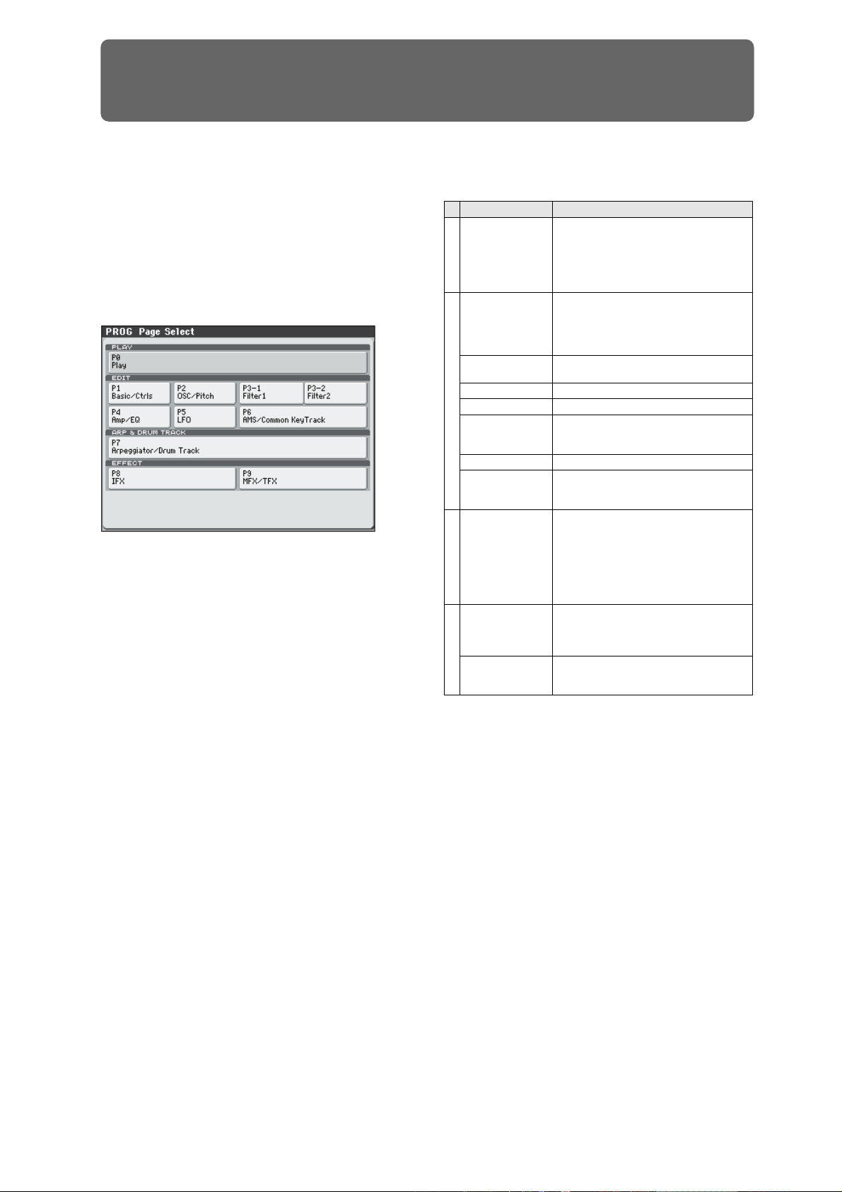
• Press the MODE PROG switch to select the Program
mode.
You can select Program mode pages in several ways.
1. Press the PAGE SELECT switch.
“Page Select” shows an abbreviated name for each page.
The page prior to pressing the PAGE SELECT switch is
shown in grey.
2. Select the desired page in the display.
Other ways to select pages
•Hold down the PAGE SELECT switch and press
numeric keys 0–9 to jump to the corresponding page.
For example, hold down the PAGE SELECT switch and
press numeric key 4 to jump to the P4: Amp/EQ page.
Note: For pages that consist of multiple subpages, such
as P3–1 and P3–2, the first of these pages (P3–1) will be
selected.
• Press the EXIT switch to return to the most recently
selected Play page. Press the EXIT switch once again to
return to the Main page.
Page Main content
Select and play programs. (
Oscillator and Drum track level settings.
(
P0: Play
PLAY
P1: Basic/Ctrls
P2: OSC/Pitch
P3–1: Filter1 Filter 1 (tone) settings. (
P3–2: Filter2 Filter 2 (tone) settings. (
EDIT
P4: Amp/EQ
P5: LFO LFO settings. (
P6: AMS/Common
KeyTrack
P7: Arpeggiator/
Drum Track
ARP & DRUM TRACK
P8: IFX
EFFECT
P9: MFX/TFX
p. 4)
Simple arpeggiator editing. (
Tone Adjust settings. (
Editing from the control surface. (
Basic program settings, such as voice assign
mode. (
p. 15)
SW1, 2, and knob settings. (
Chord trigger switch note and velocity
settings. (
Oscillator selection and pitch settings.
(
Amp 1, 2 (volume) settings. (
Amp 1, 2 driver and pan settings. (
3-band parametric EQ settings. (
AMS Mixer settings. (
Common keyboard tracking settings.
(
Arpeggiator settings. ( ☞ p. 59)
Drum track settings. (
Oscillator output bus and master effect send
level settings. (
Insert effect routing, selection, and settings.
(
Master effect routing, selection, and settings.
(
Total effect selection and settings. (
p. 20)
p. 21)
p. 48)
p. 58)
p. 66)
p. 71)
p. 2)
p. 5)
p. 8)
p. 11)
p. 18)
p. 30)
p. 40)
p. 41)
p. 47)
p. 47)
p. 52)
p. 62)
p. 65)
p. 72)
1
Page 10
Program mode
PROG P0: Play
→
q
This is the main Program mode page. Here, you can:
• Select patterns and programs for the Drum Track
•Adjust the oscillator and drum track levels.
•Make simple edits for the Arpeggiator
•Use the Tone Adjust function to make simple edits for
program parameters
•Check the control surface content, and operate it.
All MIDI data in Prog P0: Play is transmitted and
received on the global MIDI channel
(Global 1–1a).
MIDI Channel
Tip: Auto Song Setup
The Auto Song Setup feature copies the current Program or
Combination into a Song, and then puts the M50 in recordready mode.
If inspiration for a phrase or song strikes you while you’re
playing, you can use Auto Song Setup to start recording
immediately. For more information, please see “Tip: Auto
Song Setup” on page 126.
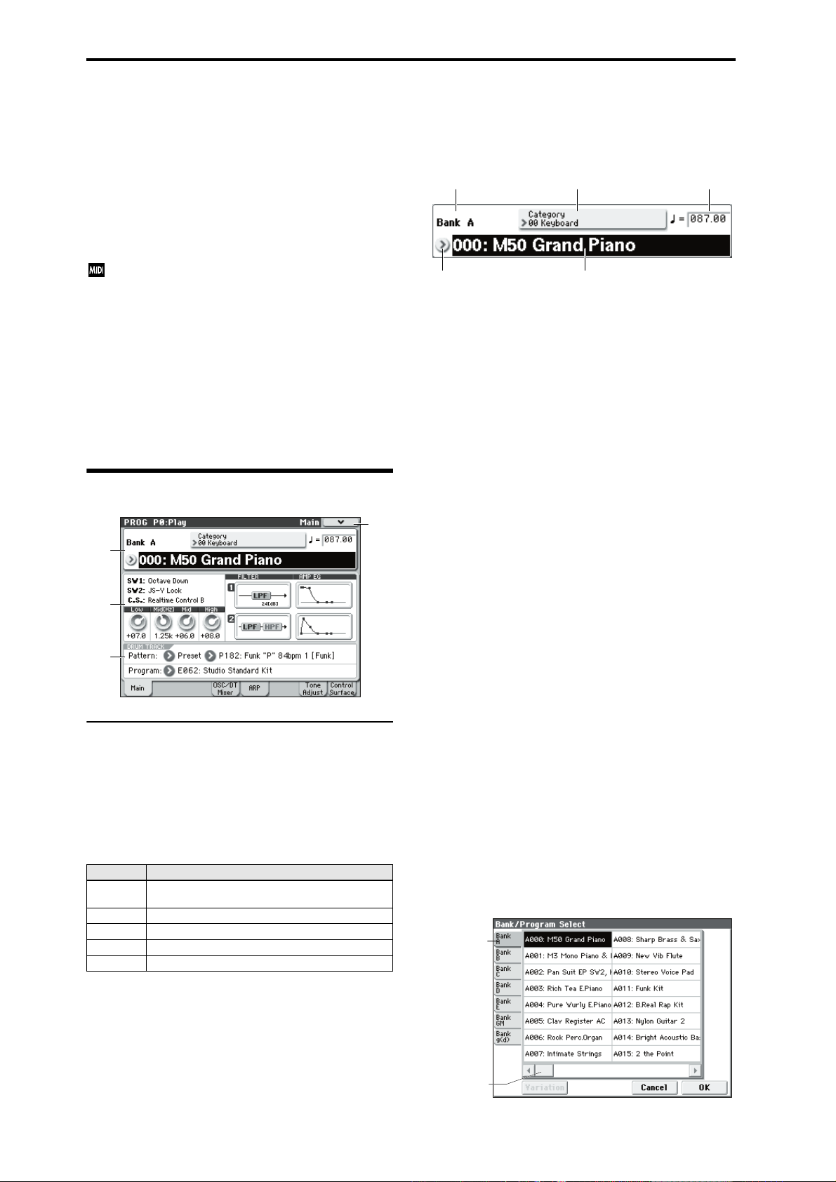
0–1: Main
0–1
Menu
0–1a
0–1b
0–1c
0–1a: Program Select
Bank (Bank Select) [A...E, GM, g(1)...g(9), g(d)]
This is the Bank containing the current Program.
Press the PROG BANK A–GM switch to select a bank.
Pressing the PROG BANK GM switch steps through the
variation banks in the following order:
g(1) → g(2)…g(8) → g(9) → g(d) → GM…
GM
Bank Main contents
A...D,
E000...095
E096...127 user programs
GM GM2 capital programs
g(1)–(9) GM2 variation programs*
g(d) GM2 drums programs
preloaded programs
For details on the factory Programs, please see the “Voice
Name List” (PDF).
Bank
Program Select Popup Program Select
Category Popup Tempo
Program Select [A…E: 0...127, GM, g(1)...g(9),
g(d): 1...128]
Here you can select a program.
To switch programs
• Choose Program Select , use the numeric keys 0–9 to
enter a program number, and press the ENTER switch.
• Choose
• From the Bank/Program Select menu, view and select
• From the Category/Program Select menu, view and
• You can use a foot switch to select programs. (see “Foot
• You can select programs by transmitting a MIDI
Program Select , and turn the VALUE dial or use
/u switches.
the
Note: You cannot use the Value slider to select programs
while in the P0: Play page; instead, the VALUE slider
operates as a program modulation source.
programs by bank.
select programs by category.
Switch Assign” on page 228 and “List of Foot Switch
assignments” on page 384)
Program Change from a connected external MIDI
device.
Bank/Program Select menu:
1. Press the popup button at the left of Program Select to
open the Bank/Program Select menu.
2. Press one of the tabs on the left or right to select a specific bank.
The Variation button is active if Bank GM is selected;
pressing it will switch the banks in the following order:
GM→g(1)→g(2)→... →g(8)→g(9)→GM.
3. From the list, You can touch a Program’s name directly,
or use the Inc q and Dec u switches.
Use the scroll bar to view information not currently shown.
4. Press the OK button to confirm your choice, or press the
Cancel button to exit without switching Programs.
Bank/Program Select menu
Tab
• Banks A–E each contain 128 rewritable programs (a total
of 640). Non-rewritable banks are organized as follows:
GM contains GM2 capital programs, g(1)–g(9) contain
GM2 variation programs, and g(d) contain GM2 drum
programs.
• The GM basic sounds will be selected for banks for
which there is no variation sound. (An “*” is displayed
at the beginning of the program name.)
2
Scroll bar
Page 11
PROG P0: Play 0–1: Main
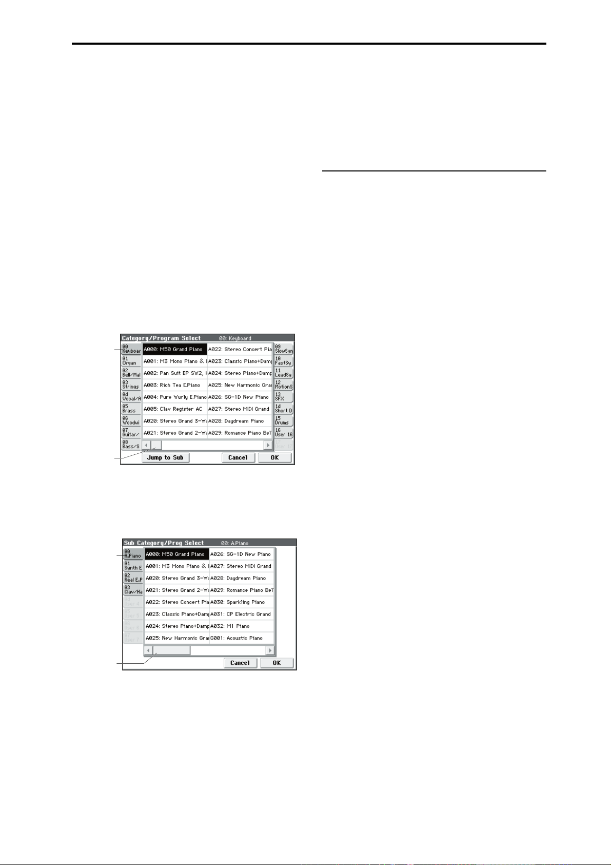
Category [00...17/00...07]
Here, you can select programs by category.
Category/Program Select menu:
Here, you can select programs by main category and subcategory. All programs are classified into eighteen main
categories, and each category is classified into eight subcategories. You can use these main categories and subcategories to find and select programs.
1. Press the Category popup button (above the Program
Select parameter) to open the Category/Program Select
menu.
2. Press one of the tabs on the left or right to select the
desired category.
Note: Only Categories and Sub-categories that are assigned
to programs can be selected from the tabs.
3. Select a program from the list.
You can touch a Program’s name directly, or use the Inc q
and Dec u switches.
Use the scroll bar to browse through all Programs in the
Category.
Category/Program Select menu
Sub-category
tab
the bpm, or just play a few quarter-notes on the TAP
TEMPO button.
EXT is displayed if the MIDI Clock (Global 1–1a) is set to
External MIDI or External USB. This is also shown if the
MIDI Clock setting is Auto and MIDI clock data is being
received from an external device. If the tempo source is EXT,
the arpeggiator etc. will synchronize to MIDI clock data
from an external MIDI device.
0–1b: Program Information
The following information for the selected program is
displayed:
SW1, SW2
These are the functions controlled by the SW1, SW2
switches.
C.S. (Control Surface)
This indicates the currently selected control assignment. The
control surface is available and active from any page.
FILTER 1, 2
This indicates the filter type setting for filter 1 and 2.
AMP EG 1, 2
This indicates the EG settings for amp 1 and 2.
Scroll bar
4. To select from a sub-category, press the Jump to Sub
button .
Press one of the left tabs to select a sub-category.
Note: Only Sub-categories that are assigned to Programs can
be selected from the tabs.
Sub-category
tab
Scroll bar
EQ (Low, Mid[Hz], Mid, High)
This indicates the 3-band EQ settings. You can edit the
values.
Low: Adjusts the gain of the 80 Hz low-shelving EQ in 0.5
dB steps.
Mid [Hz]: Adjusts the center frequency of the midsweepable EQ.
Mid: Adjusts the gain of the mid-sweepable EQ in 0.5 dB
steps.
High: Adjusts the gain of the 10 kHz high shelving EQ in 0.5
dB steps.
5. Press the OK button to confirm your choice, or press the
Cancel button to exit without changing the Program.
Note: You can assign a category to a Program in the Write
Program dialog.
(Tempo) [40.00... 300.00, EXT]
This is the tempo for the current Program, which applies to
the arpeggiator, tempo-synced LFOs, and tempo-synced
effects.
040.00...300.00 allows you to set a specific tempo in BPM,
with 1/100 BPM accuracy. In addition to using the standard
data entry controls, you can use the TEMPO knob to adjust
3
Page 12
Program mode
0–1c: Drum Track
The Drum Track provides an easy way for you to play back
a rhythm section using the M50’s high-quality drum
programs and a rich variety of drum patterns.
You can try out program phrases or edit programs while
listening to the drum track.
When you come up with a phrase you like, you can easily
record it into the sequencer using the Auto Song Setup
function.
Pattern Bank [Preset, User]
Pattern No. [P000...671, U000...999]
Select the pattern you want to use in the drum track. You can
create user patterns in Seq P10: Pattern/RPPR– Pattern Edit.
Drum Track Program [A...E: 000…127, GM,
g(1)...g(9), g(d): 001…128]
Select the program that will play the drum track pattern.
Note: You can also edit these parameters in P7: ARP/DT
(Arpeggiator/Drum Track)
The MIDI channel of the drum track is specified by the
Global P1: MIDI– MIDI Basic page DrumTrack Prog
MIDI Ch. MIDI message transmission for a pattern is
specified by Prog MIDI Out. Program changes are not
transmitted or received.
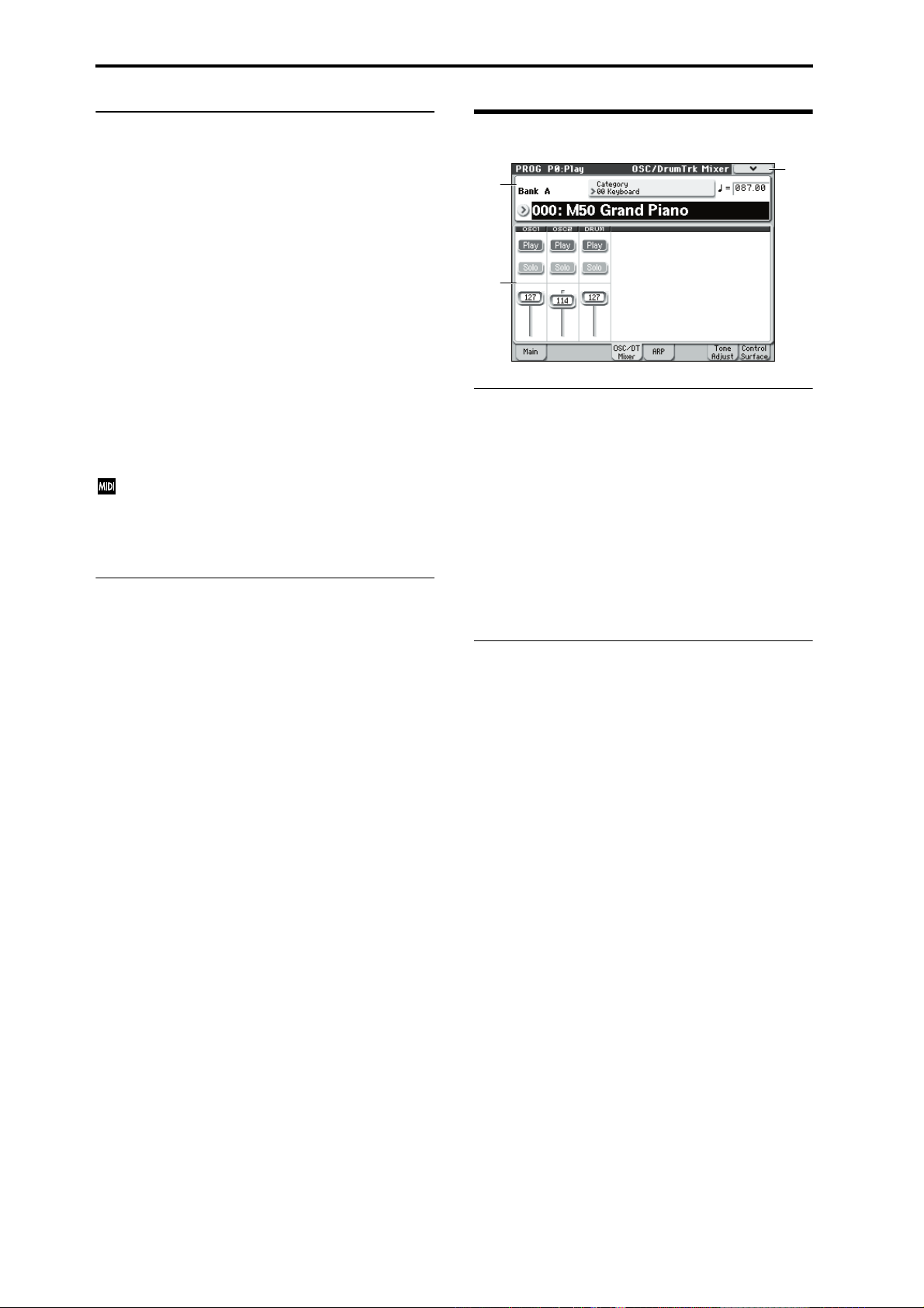
0–4: OSC/DrumTrk Mixer
0–4
0–4a
0–4b
0–4a: Program Select, Tempo
Bank (Bank Select)
[A...E, GM, g(1)...g(9), g(d)]
Program Select [A...E: 000…127, GM, g(1)...g(9),
g(d): 001...128]
This shows the bank, number, and name of the currently
selected program. Here you can also select a program. For
more information, please see “0–1a: Program Select” on
page 2.
Menu
▼0–1: Menu Command
• 0: Write Program ☞p.73
For more information, please see “Program: Menu
Command” on page 73.
(Tempo) [040.00...300.00, EXT]
For more information, please see “ (Tempo)” on page 3.
0–4b: OSC/DrumTrack Mixer
Here, you can adjust the volume and change the Play/Mute
and Solo On/Off settings of oscillators 1 and 2 and the drum
track.
OSC Play/Mute:
OSC1 Play/Mute [Play, Mute]
Play: Oscillator 1 will sound.
Mute: Oscillator 1 will be muted (silent).
OSC2 Play/Mute [Play, Mute]
Play: Oscillator 2 will sound.
Mute: Oscillator 2 will be muted (silent).
Note: OSC2 Play/Mute cannot be set for a program whose
Oscillator Mode is Single or Drums.
DRUM Play/Mute 1 [Play, Mute]
Play: The drum track will sound.
Mute: The drum track will be muted (silent).
OSC Solo:
OSC1 Solo [Off, On]
Switches the Solo status on/off for oscillator 1.
OSC2 Solo [Off, On]
Switches the Solo status on/off for oscillator 2.
DRUM Solo [Off, On]
Switches the Solo status on/off for the drum track.
Note: Solo applies to oscillators 1 and 2, the drum track.
Note: OSC2 Solo cannot be set for a program whose
Oscillator Mode is Single or Drums.
4
Page 13
Note: The Solo On/Off setting is not saved when you write
the program.
Exclusive Solo [Off, On]
The menu’s Exclusive Solo parameter also affects the way
that Solo works. If Exclusive Solo is off (unchecked),
Multiple Solos will be active, allowing you to turn Solo on/
off for more than one of the items: oscillators 1 and 2, and
the drum track. Each time you press a Solo button, the solo
setting will toggle on and off.
If Exclusive Solo is on (checked), only one of the applicable
items can be soloed. In this mode, pressing a Solo button
automatically disables any previous solos.
Tip: You can also toggle Exclusive Solo by holding ENTER
and pressing 2 on the numeric keypad.
PROG P0: Play 0–5: Arpeggiator
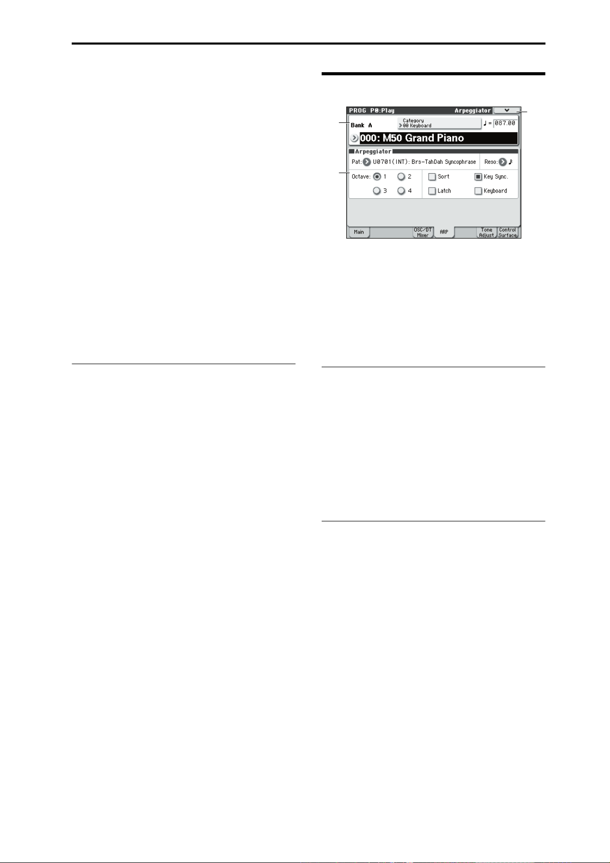
0–5: Arpeggiator
0–5a
0–5b
0–5
Menu
OSC Volume:
OSC 1 Volume [000...127]
This slider adjusts the volume of Oscillator 1.
OSC 2 Volume [000...127]
This slider adjusts the volume of Oscillator 2.
DRUM Volume [000...127]
Adjusts the volume of the drum track.
▼0–4: Menu Command
• 0: Write Program ☞p.73
• 1: Exclusive Solo ☞p. 73
For more information, please see “Program: Menu
Command” on page 73.
Arpeggiator parameters are edited in P7: ARP/DT
(Arpeggiator/Drum Track), but major parameters can be
edited here as well. When you are playing in Prog P0: Play,
you can edit the arpeggiator in realtime, such as changing
the arpeggio pattern etc.
To write (save) the edited content, use Write Program or
Update Program. You can also use the TEMPO knob and the
control surface arpeggio control (ARP) knobs GATE,
VELOCITY, LENGTH, and OCTAVE to edit the arpeggio in
realtime.
0–5a: Program Select, Tempo
Bank (Bank Select) [A...E, GM, g(1)...g(9), g(d)]
Program Select [A…E: 000...127, GM, g(1)...g(9),
g(d): 001…128]
This shows the bank, number, and name of the currently
selected program. Here, you can also select a program. For
more information, please see “0–1a: Program Select” on
page 2.
(Tempo) [040.00...300.00, EXT]
For more information, please see “ (Tempo)” on page 3.
0–5b: Arpeggiator
Pat (Pattern)
[P0...P4, U000 (INT)...U0899(INT),
U0900(USER)...U1027(USER)]
Octave [1, 2, 3, 4]
Reso (Resolution) [ , , , , , ]
Sort [Off, On]
Latch [Off, On]
Key Sync. [Off, On]
Keyboard [Off, On]
Make settings for the program arpeggiator. For more
information, please see “PROG P7: ARP/DT (Arpeggiator/
Drum Track)” on page 59.
Note: These parameters can also be set from P7: ARP/DT
(Arpeggiator/Drum Track).
5
Page 14
Program mode
▼0–5: Menu Command
• 0: Write Program ☞p.73
• 1: Exclusive Solo ☞p. 73
• 2: Copy Arpeggiator ☞p. 75
For more information, please see “Program: Menu
Command” on page 73.
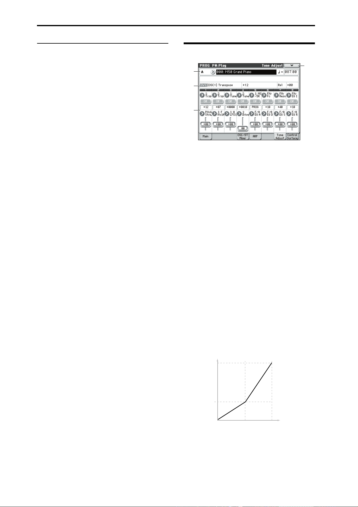
0–7: Tone Adjust
0–7
0–7a
0–7b
0–7c
The Tone Adjust function assigns important program
parameters and easy-edit parameters to the switches and
sliders in the display for quick edits of selected parameters.
Tip: In Combination and Sequencer modes, Tone Adjust also
lets you edit Program parameters without the need to save a
different version of the original Program. For more
information on Tone Adjust in these modes, please see
“Tone Adjust” on page 85 and page 135.
Absolute (Abs), Relative (Rel), Meta parameter
There are three kinds of Tone Adjust parameters: Absolute,
Relative, and Meta.
Absolute parameters usually edit a single Program
parameter, such as Oscillator 1 Drive. The Program and
Tone Adjust parameters mirror one another; when you
change one, the other will change to match.
Relative parameters typically adjust two or more Program
parameters simultaneously. For instance, F/A EG Attack
Time affects a total of six Program parameters. The value of
the Relative parameter shows the amount of change to these
underlying Program parameters.
If the Relative parameter is set to 0 (the slider in the display
is at the center position), the value of the corresponding
program parameter will not change.
The definitions of higher and lower settings can vary,
depending on the specific parameter. Unless noted
otherwise, they work as follows:
When the Relative parameter is at +99 (the maximum), the
Program parameters are all at their maximum as well.
Similarly, when the Relative parameter is at –99 (the
minimum), the Program parameters are at zero.
Relative Tone Adjust parameter scaling
Menu
99
Parameter
Value
As Programmed
00
0–99 +99
Relative Tone Adjust Value
A few of the Program parameters controlled by Relative
Tone Adjust are bipolar, meaning that they can be either
positive or negative (instead of just positive). When these
Program parameters are set to negative values, the Tone
Adjust parameter may behave differently from the
description above.
6
Page 15
PROG P0: Play 0–7: Tone Adjust
For instance, if the EG Intensity is set to a negative value,
Relative Tone Adjust values will range from 0 to –99, the
inverse of the diagram above. EG Sustain works differently;
if it’s set to a negative value, Tone Adjust values range from
0 down to the programmed value, and then up to +99, as
shown below.
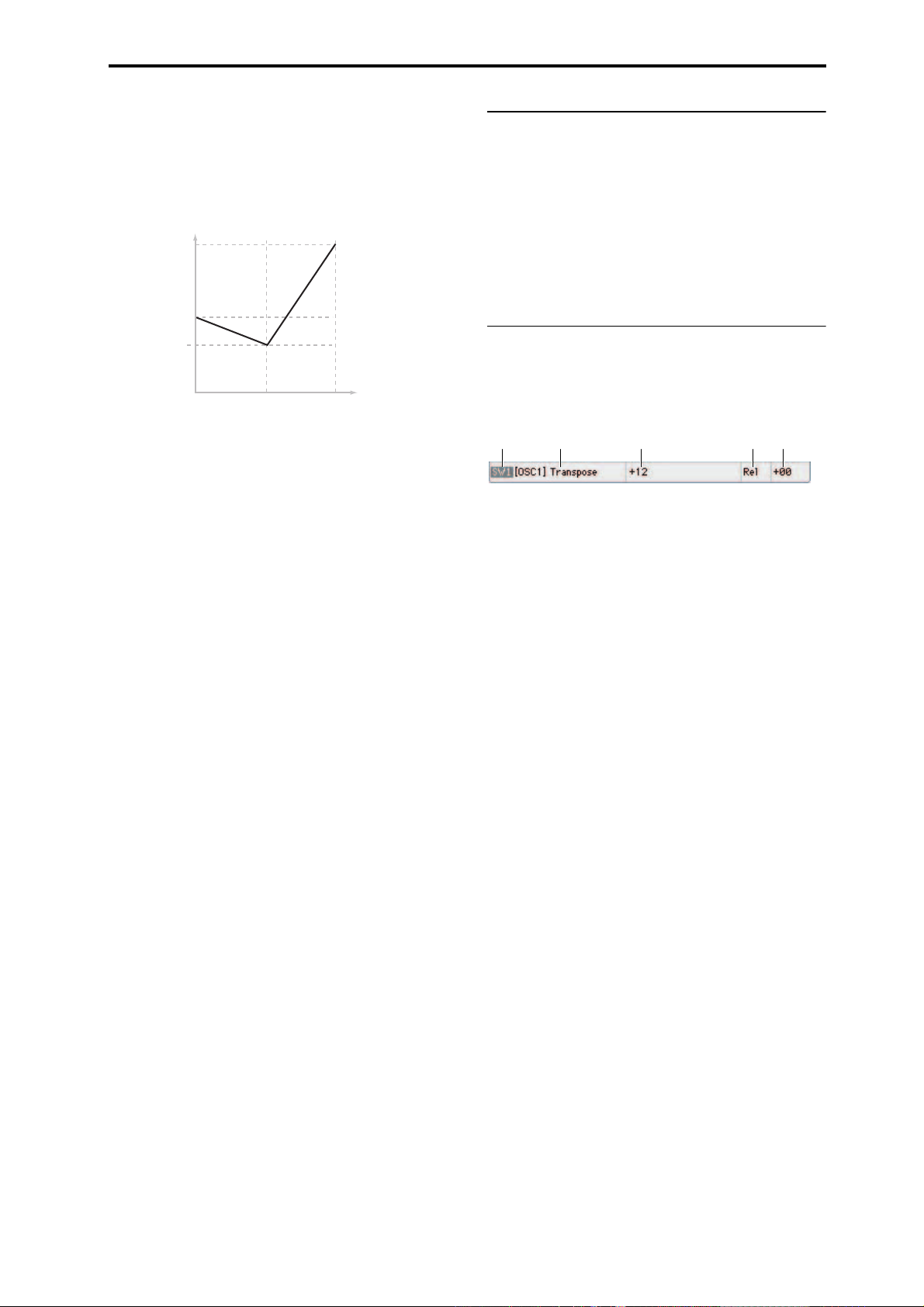
Relative Tone Adjust parameter scaling: EG Sustain
99
Parameter
Value
00
As Programmed
–99
0–99 +99
Relative Tone Adjust Value
Meta parameters don’t affect Program parameters directly.
Instead, they affect the way that other Tone Adjust
parameters work. For instance, Multisample Min # and
Max # set the minimum and maximum values of the Tone
Adjust Multisample parameter.
Saving Tone Adjust Edits
Tone Adjust edits are saved in two different ways,
depending on whether the parameter is Relative or
Absolute. (For more information, please see “Absolute
(Abs), Relative (Rel), Meta parameter,” below.)
Edits to Relative parameters affect the sound immediately,
but don’t change the underlying Program parameter
settings until the Program is saved. When the Program is
saved, the M50 calculates the combined effects of Tone
Adjust and dedicated CC modulation (from the Real Time
knobs, for instance), and saves the results into the Program
parameters directly. At that point, all of the Relative
parameters are reset to 0.
Edits to Absolute parameters are immediately reflected in
the corresponding on-screen parameters, and vice-versa.
Tone Adjust and MIDI SysEx
The Tone Adjust edits all send and receive MIDI System
Exclusive messages. You can use this to record and play
back Tone Adjust edits with a sequencer, including the builtin sequencer.
Note: System exclusive messages are not Tone Adjust
parameters; they are linked to the actual value. For example,
if a slider in the display is assigned to control filter
resonance, and you move this slider while recording to the
sequencer, the slider movement will be recorded, but the
change in filter resonance will not be recorded. This means
that if you later reassign the Tone Adjust parameter to
control LFO1 Speed, playing back the sequencer will cause
the LFO speed (not the filter resonance) to change.
0–7a: Program Select & Tempo
Bank (Bank Select) [A...E, GM, g(1)...g(9), g(d)]
Program Select [A...E: 000…127, GM, g(1)...g(9),
g(d): 001…128]
(Tempo) [040.00...300.00, EXT]
This area displays information about the program selected
for editing: the program bank/number/ name, and the
tempo used to control the arpeggiator etc. For more
information, please see “0–1a: Program Select” on page 2.
0–7b: Selected parameter information
Selected parameter information
This status line shows detailed, read-only information about
the currently selected Tone Adjust parameter.
Control Assignment Value Stored ValueType
Control [SW1...8, SL1...8]
This is the controller in the display to which the Tone Adjust
parameter is assigned.
SW: Switch
SL: Slider
Assignment
This shows the full name of the parameter assigned to the
controller. You can change this using the Assign parameter,
below.
Value
This shows the current value of the parameter. The range of
values will vary depending on the parameter assigned to the
control.
Type [Rel, Abs, Meta]
This shows the type of parameter, which relates to how edits
to the parameter are adjusted and saved. For more
information, please see “Absolute (Abs), Relative (Rel),
Meta parameter” on page 6.
Stored Value
This shows the original value of the parameter, before the
effects of Tone Adjust. It applies only to Tone Adjust
parameters which control a single Program parameter.
If you un-assign a Relative parameter from a control, it will
revert to this value.
Interaction between Tone Adjust and MIDI CCs
A number of the Common Tone Adjust parameters can
affect parameters which are also modulated by dedicated
MIDI CCs. The specific CC numbers are noted in the
descriptions for the individual Tone Adjust parameters. For
more information, please see “Tone Adjust Parameters” on
page 9.
Tone Adjust and the CCs work independently. It’s possible,
for instance, for Tone Adjust to reduce the value of a
parameter, and then for a CC to increase it again.
Tone Adjust scales the parameter first, and then the CC
scales the result of the Tone Adjust.
7
Page 16

Program mode
A
V
A
V
0–7c: Tone Adjust
Here, you can assign Tone Adjust parameters to switches
and sliders in the display.
Switches 1...8
Tone Adjust switches in the display act a little differently
than sliders.
When a switch is assigned to a Relative parameter, or an
Absolute parameter with more than two states:
Switch On = On Value (see below)
Switch Off = the Program’s stored value
When a switch is assigned to a two-state Absolute
parameter, such as Hold, the switch status directly reflects
the parameter value:
Switch On = On
Switch Off = Off
ssign
On/Off
alue
Assign
This lets you assign a Tone Adjust parameter to the
displayed switch. For a full list of the available choices,
please see “Common Tone Adjust Parameters” and “Tone
Adjust Parameters,” below.
On Value [Depends on parameter]
The parameter is set to this value when the switch is On.
When the switch is assigned to a two-state Absolute
parameter, such as Hold, this will always be the same as the
Switch Status (see below).
Switch Status [Off, On]
This simply shows whether the switch is On or Off.
Sliders 1...8
Assign
This lets you assign a Tone Adjust parameter to the
displayed slider. For a full list of the available choices, please
see “Common Tone Adjust Parameters” and “Tone Adjust
Parameters,” below.
ssign
alue
Per-Oscillator parameters apply to OSC1 and 2 individually,
and are marked as such: OSC1 and OSC2.
Each slider can be assigned to only one parameter, and each
parameter can be assigned to only one slider.
To swap a parameter from one slider to another, you’ll need
to first un-assign it from the old slider, and then assign it to
the new slider.
Value
This shows the current value of the parameter. The range of
values will depend on the parameter assigned to the slider.
Common Tone Adjust Parameters
These parameters affect both Oscillators 1 and 2.
Unless otherwise noted, all of the Common Tone Adjust
parameters are Relative.
Note: At the right of each parameter, the (value range and
CC#) are shown in parentheses.
Off. This means that the Tone Adjust control has no effect.
Filter Cutoff. (–99...+99, CC#74)
This scales the cutoff frequency of all of the filters at once. It
affects both Filters A and B.
Filter Resonance. (–99...+99, CC#71)
This scales the resonance of all of the filters at once. It affects
both Filters A and B.
Filter EG Intensity. (–99...+99, CC#79)
This scales the effect of the Filter EG on the cutoff frequency.
It affectsFilters A and B simultaneously.
–99 means no modulation. +99 means maximum.
Modulation is in the same direction, positive or negative, as
the original Program. For instance, if the original Program’s
EG Intensity was set to –25, then setting the Tone Adjust to
+99 moves the EG Intensity to –99.
Amp Velocity Intensity. (–99...+99)
This scales the effect of velocity on the Amp level.
–99 removes the velocity modulation entirely. +99 means
maximum modulation in the same direction, positive or
negative, as the original Program.
F/A EG Attack Time. (–99...+99, CC#73)
This scales the attack times of the Filter and Amp EGs, along
with other related parameters.
When the value is +1 or more, this also affects the Amp EG’s
Start and Attack Levels, Start Level AMS, and Attack Time
AMS, as described below:
Between values of +1 and +25, the Start Level, Start Level
AMS, and Attack Time AMS will change from their
programmed values to 0. Over the same range, the Attack
Level will change from its programmed value to 99.
F/A EG Decay Time. (–99...+99, CC#75)
This scales the decay and slope times of the Filter and Amp
EGs. It interacts with CC# 75.
F/A EG Sustain Level. (–99...+99, CC#70)
This scales the sustain levels of the Filter and Amp EGs.
F/A EG Release Time. (–99...+99, CC#72)
This scales the release times of the Filter and Amp EGs.
Filter EG Attack Time. (–99...+99)
This scales the attack times of the Filter EGs.
Filter EG Decay Time. (–99...+99)
This scales the decay and slope times of the Filter EGs.
Filter EG Sustain Level. (–99...+99)
This scales the sustain levels of the Filter EGs.
Filter EG Release Time. (–99...+99)
This scales the release times of the Filter EGs.
Amp EG Attack Time. (–99...+99)
This scales the attack times of the Amp EGs.
Amp EG Decay Time. (–99...+99)
This scales the decay and slope times of the Amp EGs.
Amp EG Sustain Level. (–99...+99)
This scales the sustain levels of the Amp EGs.
Amp EG Release Time. (–99...+99)
This scales the release times of the Amp EGs.
Pitch EG Attack Time. (–99...+99)
This scales the attack times of the Pitch EG.
Pitch EG Decay Time. (–99...+99)
This scales the decay and slope times of the Pitch EG.
8
Page 17

PROG P0: Play 0–7: Tone Adjust
Pitch EG Sustain Level (N/A). (–99...+99)
This scales the sustain levels of the Pitch EG.
Pitch EG Release Time. (–99...+99)
This scales the release times of the Pitch EG.
Pitch LFO1 Intensity. (–99...+99, CC#77)
This scales the effect of LFO1 on the Pitch.
–99 removes the LFO modulation entirely. +99 means
maximum modulation in the same direction, positive or
negative, as the original Program.
LFO1 Speed. (–99...+99, CC#76)
This scales LFO1’s frequency. When the LFO is in MIDI/
Te mpo mode, this adjusts the Base Note. For more
information, please see “Freq (Frequency)” on page 48.
LFO1 Fade. (–99...+99)
This scales LFO1’s fade-in time. For more information,
please see “Fade” on page 49.
LFO1 Delay. (–99...+99, CC#78)
This scales LFO1’s delay time - the time between note-on
and the onset of the LFO. For more information, please see
“Delay” on page 49.
This parameter interacts with CC# 78.
LFO1 Stop. (PROG/Off/On, Absolute)
This Absolute parameter controls whether LFO1 is stopped
or running. For more information, please see “Stop” on
page 48.
The PROG setting restores the Program’s original values.
For example, if you set this to PROG when the oscillator 1
LFO is stopped and oscillator 2 is playing, the original
setting of the parameter will be used.
LFO2 Speed. (–99...+99)
This scales LFO2’s frequency. When the LFO is in MIDI/
Te mpo mode, this adjusts the Base Note. For more
information, please see “Freq (Frequency)” on page 48.
LFO2 Fade. (–99...+99)
This scales LFO2’s fade-in time. For more information,
please see “Fade” on page 49.
LFO2 Delay. (–99...+99)
This scales LFO2’s delay time - the time between note-on
and the onset of the LFO. For more information, please see
“Delay” on page 49.
LFO2 Stop. (PROG/Off/On, Absolute)
This Absolute parameter controls whether LFO2 is stopped
or running. For more information, please see “Stop” on
page 48.
Common LFO Speed. (–99...+99)
This scales the Common LFO’s frequency. When the LFO is
in MIDI/Tempo mode, this adjusts the Base Note.
Unison. (Off/On, Absolute)
This Absolute parameter turns Unison on and off. For more
information, please see “Unison” on page 16.
Number Of Voices. (2...6, Absolute)
This Absolute parameter sets the number of Unison voices.
If Unison is not On, this parameter has no effect. For more
information, please see “Number of Voices” on page 16.
Detune. (00...99, Absolute)
This Absolute parameter sets the amount of detuning
between the Unison voices. If Unison is not On, this
parameter has no effect. For more information, please see
“Detune” on page 16.
Thickness. (Off/01...09, Absolute)
This Absolute parameter sets the pattern of detuning
between the Unison voices. If Unison is not On, or if Detune
is set to 0, this parameter has no effect. For more
information, please see “Thickness” on page 16.
Tone Adjust Parameters
Macro parameters
The following three parameters affect both Oscillator 1 and
Oscillator 2.
Note: In the list below, at the right of each parameter, the
value range and edit type are shown in parentheses.
Pitch Stretch. (–12...+12, Relative)
This special control increases the Oscillator Tune parameter
while lowering the Transpose parameter. The result is that
the pitch stays the same, but the mapping of the samples to
the keys changes. You can use this to create interesting shifts
in timbre.
Hold. (Off/On, Absolute)
This lets you turn Hold on and off. For more information,
please see “Hold” on page 17.
Reverse. (PROG/Off/On, Absolute)
This provides a quick way to turn Reverse on or off for all
Multisamples in both Oscillators. PROG restores the
Program’s original settings. Reverse plays the waveform
from end to start; the effect is only noticeable with unlooped
samples.
Per-Oscillator parameters
These parameters affect each Oscillator separately. In the
list, the parameters for Oscillator 1 appear first, with each
name prefaced by OSC1; the parameters for Oscillator 2
appear next, prefaced by OSC2.
Unless otherwise specified, all of the Per-Oscillator
parameters are Absolute.
Note: In the list below, the items in parentheses are (value,
edit type) respectively.
Tune. (–1200...+1200, Relative)
This Relative parameter adds to or subtracts from the
Oscillator’s Tune setting, as described under “Tune” on
page 22.
Transpose. (–60...+60, Relative)
This Relative parameter adds to or subtracts from the
Oscillator’s Transpose setting, as described under
“Transpose” on page 22.
Note: as with Transpose, below, this is a simple addition or
subtraction, as opposed to the more complex “scaling”
function.
MS/DKit Select. (PROG/0...1076, Absolute)
In Single or Double Programs, this lets you select a new
Multisample for the Oscillator. In Drum Programs, it lets
you select a different Drum Kit.
In general, it’s best to use this in conjunction with the MS
Type and MS/DKit Bank parameters, as described below.
PROG restores the Program’s original Multisamples (or the
Drum Kit, for a Drum Program), including all velocity
ranges and Rev (Reverse) and Ofs (Start Offset) settings.
The list of Multisamples, or Drum Kits can be quite long.
The VALUE sliders of the front panel will let you sweep
through the entire range, but it may not be possible to select
all of the intermediate values. You can always select any
individual item by selecting the on-screen parameter and
using the standard data entry controls, such as the Inc q
and Dec u switches.
You can also limit the range of the control by using the Min
# and Max # parameters, described below.
9
Page 18

Program mode
For Single and Double Programs:
MS/DKit Select overrides all of the Multisample Velocity
zones, so that the newly selected Multisample plays over the
entire velocity range.
By default, you can select from the same Bank as the original
Program’s MS1.
You can use the MS/DKit Bank parameter, described below,
to change these defaults as desired.
For Multisamples only:
You can use the Tone Adjust Rev (Reverse) and Ofs (Start
Offset) parameters to modify the newly selected
Multisample. By default, the Rev (Reverse) is set to Off, and
its Ofs (Start Offset) is set to 0.
For Drum Programs:
By default, you can select from the same Bank as the original
Program’s DrumKit. You can use the MS Bank parameter,
described below, to select a different Bank.
MS Bank. (Mono, Stereo..., Meta)
This Meta-parameter modifies the MS/Dkit Select
parameter, so that you can select Multisamples from any
Bank you like.
MS/DKit Min #. (0...56, Meta)
This Meta-parameter sets a minimum value for the MS/Dkit
Select parameter. You can use this in conjunction with the
MS/DKit Max # parameter, below, so that front panel slider
selects only from a small set of choices. This is particularly
convenient with the internal ROM, in which similar
Multisamples are grouped together. For instance, this makes
it easy to select between a group of bells, or a set of electric
basses.
MS/DKit Max #. (0...56, Meta)
This Meta-parameter sets a maximum value for the MS/
Dkit Select parameter. Please see MS/DKit Min #, above,
for more information.
Start Offset. (0ff, 1th...8th, Absolute)
This allows you to change the Start Offset of the
Multisample specified by the MS Select parameter. It
applies only when:
The Program is a Single or Double (not a Drum Kit)
For more information, please see “Ofs (Start Offset)” on
page 22.
Drive. (0...99, Absolute)
This controls the Oscillator’s Drive parameter, as described
under “Drive” on page 41.
Low Boost. (0...99, Absolute)
This controls the Oscillator’s Low Boost parameter, as
described under “Low Boost” on page 41.
Pitch Slope. (–1.0...2.0, Absolute)
This controls the Oscillator’s Pitch Slope parameter, as
described under “Pitch Slope” on page 23.
LFO 1 Waveform. (Triangle...Rad6, Absolute)
This selects the waveform for the Oscillator’s LFO 1, as
described under “Waveform” on page 48.
LFO 2 Waveform. (Triangle...Rnd6, Absolute)
This selects the waveform for the Oscillator’s LFO 2, as
described under “Waveform” on page 48.
Amp LFO 1 Intensity. (–99...+99, Absolute)
This controls the depth and direction of Amp modulation
from LFO1, as described under “Intensity (LFO1)” on
page 44.
Amp LFO 2 Intensity. (–99...+99, Absolute)
This controls the depth and direction of Amp modulation
from LFO2, as described under “Intensity (LFO1)” on
page 44.
Filter LFO 1 Intensity to A. (–99...+99, Absolute)
This controls the depth and direction of Filter A cutoff
modulation from LFO1, as described under “Intensity to A”
on page 36.
Filter LFO 1 Intensity to B. (–99...+99, Absolute)
This controls the depth and direction of Filter B cutoff
modulation from LFO1, as described under “Intensity to B”
on page 36.
Filter LFO 2 Intensity to A. (–99...+99, Absolute)
This controls the depth and direction of Filter A cutoff
modulation from LFO2, as described under “Intensity to A”
on page 36.
Filter LFO 2 Intensity to B. (–99...+99, Absolute)
This controls the depth and direction of Filter B cutoff
modulation from LFO2, as described under “Intensity to B”
on page 36.
Pitch LFO 1 AMS Intensity. (–12.00...+12.00, Absolute)
You can use an AMS source, such as aftertouch, to modulate
the depth of pitch modulation (vibrato) from LFO1. This
controls the intensity of that AMS modulation. For more
information, please see “Intensity” on page 24.
Pitch LFO 2 AMS Intensity.
This is similar to Pitch LFO 1 AMS Intensity, above.
(–12.00...+12.00, Absolute)
10
Page 19
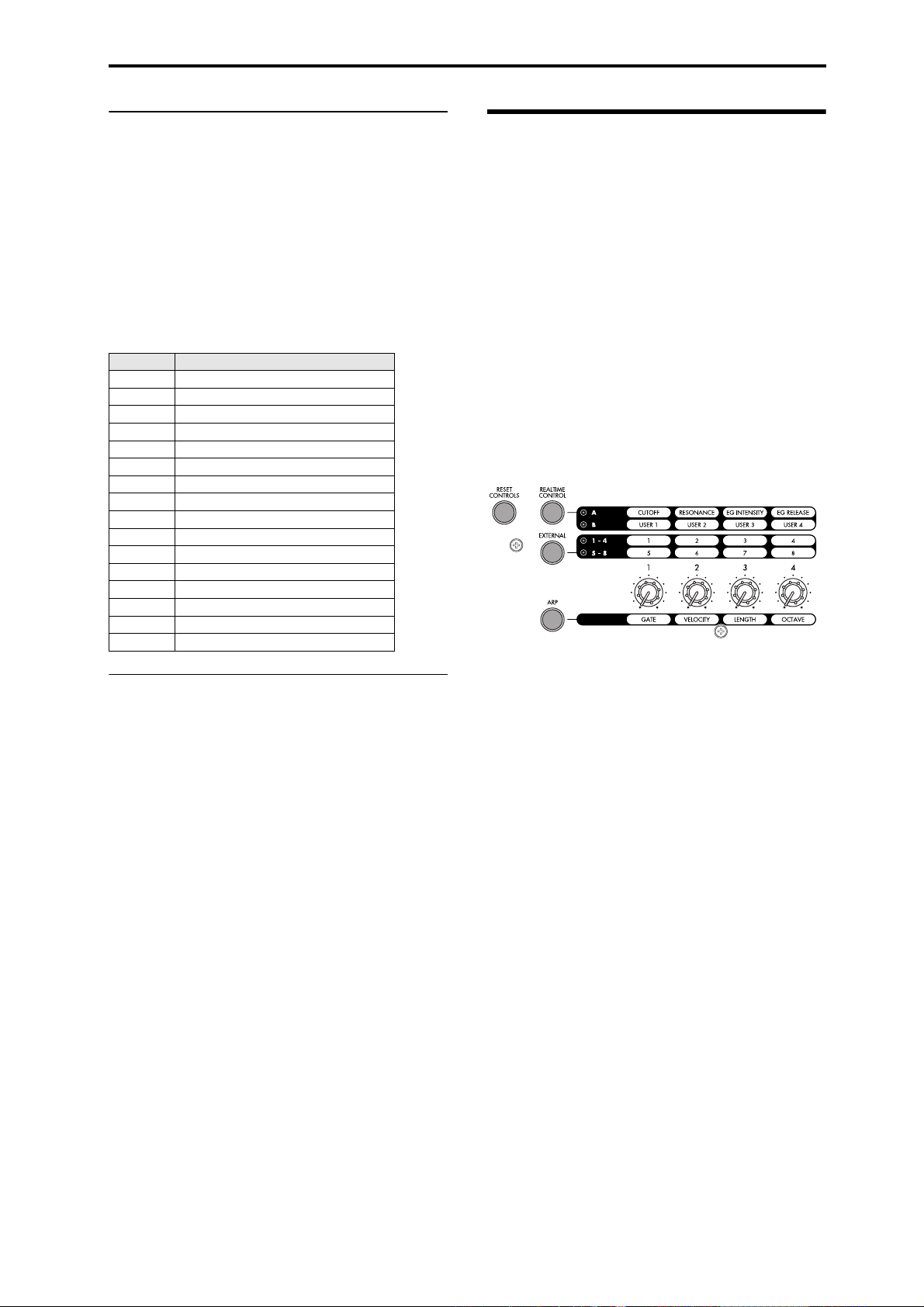
PROG P0: Play 0–8: Control Surface
Default Tone Adjust Settings
You can use the Tone Adjust function to edit all of the
important program parameters on this single page. Most of
the preset sounds use the default layout shown below. You
can customize these default settings for each program.
For details on the Tone Adjust function, please see “0–7b:
Selected parameter information” on page 7.
Tone Adjust parameters
This applies to common tone adjust parameters and tone
adjust parameters following the “0–7b: Selected parameter
information” on page 7.
Default Tone Adjust Settings
Controller Default settings
SW1 [OSC1] Transpose
SW2 [OSC2] Transpose
SW3 [OSC1] Tune
SW4 [OSC2] Tune
SW5 [OSC1]MS/DKit Select
SW6 Filter Cutoff
SW7 Filter Resonance
SW8 Filter EG Intensity
Slider1 [OSC1&2] Pitch Stretch
Slider2 [OSC1] Filter LFO1 Int A
Slider3 [OSC1] Amp LFO Int
Slider4 [OSC1] Drive
Slider5 F/A EG Attack Time
Slider6 F/A EG Decay Time
Slider7 F/A EG Sustain Level
Slider8 F/A EG Release Time
▼0–7: Menu Command
• 0: Write Program ☞p.73
• 1: Exclusive Solo ☞p. 73
• 2: Copy Tone Adjust ☞p. 74
• 3: Reset Tone Adjust ☞p. 74
For more information, please see “Program: Menu
Command” on page 73.
0–8: Control Surface
The control surface consists of the four knobs located in the
left side of the front panel and the four switches to their left.
You can use this control surface in a variety of ways, such as
editing the sound or effects, controlling the arpeggiator, or
transmitting MIDI messages to external devices.
This page shows you the current values for each of the
knobs, along with information about what they are
controlling. For instance, you can:
• Use the knobs to modulate sounds and effects
• Use the knobs to transmit MIDI messages to external
MIDI devices
• Use the knobs to control the arpeggiator
CONTROL ASSIGN switches and parameters
You can use Control Assign in the display or the front panel
REALTIME CONTROL, EXTERNAL, ARP switches to
switch the function of control surface. Because the display
and the front panel switches are linked, changing one will
change the other correspondingly.
In Program mode, you can select one of three different
functions:
Realtime Control: Use the knobs to control the sound or
effects.
External lets you send MIDI messages to external MIDI
devices. Use the Global P1: MIDI– External Mode 1/2 page
to select the MIDI message you wish to transmit.
ARP: Use the knobs to control the Arpeggiator function.
You can freely change back and forth between the different
functions, without losing any of your edits.
Reset controls
The front panel RESET CONTROLS switch lets you restore
the desired knobs of the control surface to the stored values.
You can also use this to reset the Arpeggiator settings. For
more information, please see “Resetting the controller
settings” on page 21 of the Owner’s manual.
Resetting a single control
To reset a single knob:
1. Hold down the RESET CONTROLS switch.
2. While holding down RESET CONTROLS, move a
knob or press one of the control surface switches.
The knob will be reset to the value stored in the Program.
3. When you’re done, release the RESET CONTROLS
switch.
Resetting a group of controls
1. Use the display’s Control Assign or the front panel
CONTROL ASSIGN switches to access the controllers
you want to reset.
Note: As a safety precaution, you can only reset the
parameters currently displayed on the Control Surface.
2. Hold down the RESET CONTROLS switch.
11
Page 20
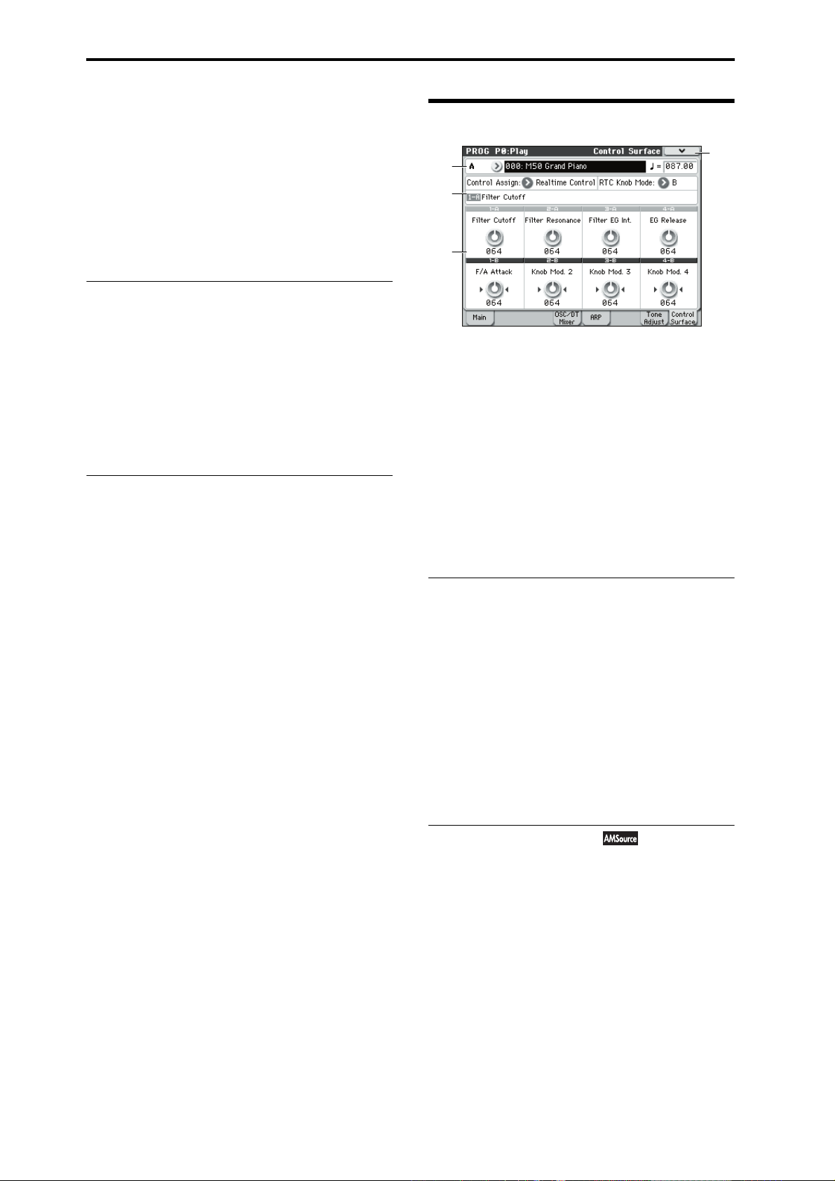
Program mode
3. While holding down RESET CONTROLS, press the
current CONTROL ASSIGN switch again.
All of the knobs shown on the Control Surface will be reset
to the values stored in the Program.
Resetting Arpeggiator parameters
You can also perform the following reset operations for
Arpeggiator.
• To reset the knobs or switches of each arpeggiator, hold
down the RESET CONTROLS switch and press the ARP
switch.
0–8a: Program Select & Tempo
Bank (Bank Select) [A...E, GM, g(1)...g(9), g(d)]
Program Select [A…E: 000…127, GM, g(1)...g(9),
g(d): 001…128]
(Tempo) [040.00...300.00, EXT]
This area displays information about the program selected
for editing: the program bank/number/ name, and the
tempo settings for the arpeggiator, etc. For more
information, please see “0–1a: Program Select” on page 2.
0–8b: Control Assign
Control Assign [Realtime Control, External, ARP]
This selects the items that will be affected by the control
surface. You can also press one of the CONTROL ASSIGN
switches to make this selection.
For details on each selection, please see the explanations that
follow.
Realtime Controls
0–8
0–8a
0–8b
0–8c
Realtime Control lets you use the four knobs to edit the
parameters of a program or effect.
There are two modes of realtime control: A and B. Press the
REALTIME CONTROL switch to toggle between these two
modes. In each mode, you can use knobs 1–4 to control
parameters. Your selection of mode is remembered
independently for Program mode, Combination mode, and
Sequencer mode. If you switch to a different control surface
function, and then press the REALTIME CONTROL switch
to return to realtime control; the mode you had selected will
still be active.
In A mode, the functions assigned to knobs 1–4 are fixed. In
B mode, you can assign a variety of modulation functions to
knobs 1–4. To assign functions, use the P1: Basic/Ctrls–
Controllers Setup page (page 15).
0–8b: Control Assign, RTC Knob Mode,
Selected Parameter Information
Menu
Control Assign [Realtime Control, External, ARP]
This selects the items that will be controlled by the control
surface.
RTC Knob Mode [A, B]
Selects either A or B as the realtime control mode for the
knobs. You can also use the front panel REALTIME
CONTROL switch to make this selection.
Selected Parameter information
When you select a knob, this area shows detailed
information about its parameter assignments.
0–8c: Realtime Control
RealTime Control A knob 1–4 (Knob1A–Knob4A) all have
dedicated functions which correspond to MIDI CCs.
RealTime Control B knob 1–4 (Knob1B–Knob4B) can be
assigned to a wide variety of functions, many of which also
have corresponding MIDI CCs.
When you move a knob, it sends out the corresponding
MIDI CC.
Unless otherwise noted, “scaling” means that the
parameters are at their programmed values when the
controller is at 64, at their minimum when the controller is at
0, and at their maximum when the controller is at 127. For
another look at this, please see the diagram below.
12
Page 21
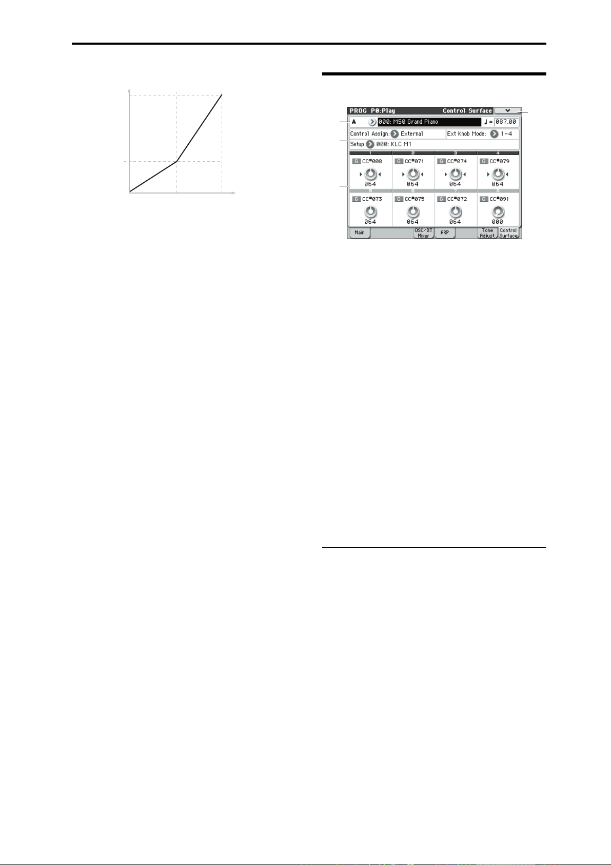
CC parameter scaling
99
Parameter
Value
As Programmed
External
0–8a
0–8b
PROG P0: Play External
0–8
Menu
00
640 127
CC Value
Knob 1A: Flt Fc (Filter Cut Off) [000...127]
This knob scales the cutoff frequencies of Filters A and B,
and transmits and receives MIDI CC #74.
Knob 2A: Flt Reso (Filter Resonance) [000...127]
This knob scales the resonance of Filters A and B, and
transmits and receives MIDI CC #71.
Knob 3A: Flt EG (Filter EG Intensity) [000...127]
This knob scales the effect of the Filter EG on the cutoff
frequencies of Filters A and B. It also transmits and receives
MIDI CC#79.
Knob 4A: EG Rel (EG Release) [000...127]
This knob scales the release time of the Filter and Amp EGs,
and transmits and receives MIDI CC#72.
Knob 1B–Knob 4B [000...127]
This is the current value of the knob and its MIDI CC.
You can set Realtime Control B knob 1–4 to a wide variety of
modulation functions, using the P1: Basic/Ctrls– Controllers
Setup page.
Many of the functions scale a particular set of Program
parameters. All of the settings also correspond to MIDI
messages–usually CCs.
0–8d
External control lets you transmit MIDI messages to external
devices.
There are two modes of external control: EXT 1–4 and EXT
5–8. These two modes will alternate each time you press the
EXTERNAL switch. In each mode, the MIDI CC# assigned
to each knob will be transmitted on the MIDI channel when
you operate knobs 1–4.
You can also assign a note or MIDI CC# to the chord trigger
switch for transmission on a specified MIDI channel. (See
“1–3: External Mode 1” on page 224 and “1–4: External
Mode 2”)
You can create 128 different external setups in the Global P1:
MIDI– External Mode 1, 2 pages. For instance, you might
make one setup for controlling several different pieces of
MIDI gear on stage, another for controlling a software
synthesizer (such as one of Korg’s Legacy Collection
synths), and so on.
These External Controls are completely independent from
the Program. You can think of External mode as being a
separate control surface that just happens to share the M50’s
knobs, and chord trigger switches.
When you select an External conrol, it stays selected even
when you change Programs, or switch to Combination or
Sequencer modes. This makes it easy to select different M50
sounds without disrupting any external MIDI control, and
vice-versa.
0–8b: Control Assign, Ext Knob Mode,
Setup
Control Assign [Realtime Control, External, ARP]
This selects the items that will be affected by the control
surface.
Ext Knob Mode [1–4, 5–8]
Selects either EXT 1–4 or EXT 5–8 as the external control
mode for the knobs. You can also use the front panel
EXTERNAL switch to make this selection.
Setup [000...127]
This selects the Global setup for the knobs and chord trigger
switches.
Note: Your selection here is stored in internal memory; it is
not saved for each program. When you press the
EXTERNAL switch to select external control, the previouslyselected external setup will be active.
13
Page 22
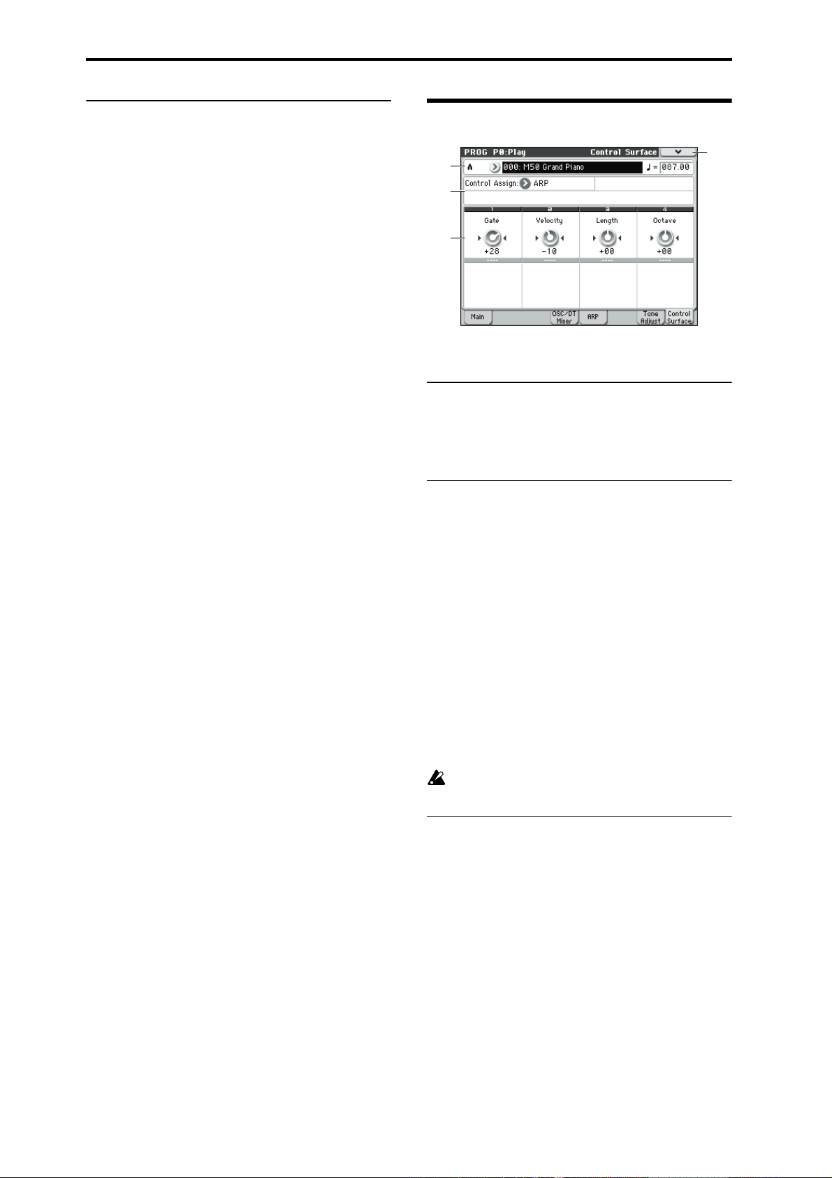
Program mode
0–8d: External
MIDI Channel [01...16, G]
This read-only parameter shows the MIDI Channel
assignment for the knob. Each can send on a different
channel, if desired.
G means that the knob will transmit on the Global MIDI
Channel, as set in Global mode.
CC# Assign [Off, 000...119]
This read-only parameter shows the MIDI CC sent by the
knob.
Value [000...127]
This is the current value of the knob’s MIDI CC.
ARP
0–8
0–8a
0–8b
0–8e
Arpeggio control lets you use the four knobs to control the
arpeggiator performance in realtime.
0–8b: Control Assign
Control Assign [Realtime Control, External, ARP]
This selects the items that will be affected by the control
surface.
0–8e: Arpeggiator
The functions of knobs 1–4 are fixed. The knobs will control
the duration of the arpeggiated notes, their velocity, the
pitch range, and the length of the arpeggio pattern.
Menu
Knob 1: Gate [–64...+00...+64]
Adjusts the duration (gate time) of the arpeggiated notes
(See “Gate” on page 60).
Knob 2: Velocity [–64...+00...+64]
Adjusts the velocity of the arpeggiated notes (See “Velocity”
on page 60).
Knob 3: Length [–64...+00...+64]
Adjusts the length of the arpeggio pattern.
Knob 4: Octave [–64...+00...+64]
Adjusts the pitch range over which the arpeggiator will play,
in one-octave steps (See “Octave*” on page 59).
If Arpeggio Tone Mode is set to Fixed Note, operating
knob 4 will not affect the pitch range.
▼0–8: Menu Command
• 0: Write Program ☞p.73
• 1: Exclusive Solo ☞p. 73
For more information, please see “Program: Menu
Command” on page 73.
14
Page 23

PROG P1: Basic/Ctrls (Basic/Controllers) 1–1: Program Basic
PROG P1: Basic/Ctrls (Basic/Controllers)
notes will use the legato start point specified for each
1–1: Program Basic
This page contains all of the basic settings for the Program.
Among other things, you can:
• Set up the Program to be a Single, a Double, or a Drum
Kit
• Set the Program to play polyphonically or
monophonically
• Enable/disable the half-damper function
1–1
1–1a
1–1b
1–1c
1–1a: Oscillator Mode
Oscillator Mode [Single, Double, Drums]
Specifies the Program’s oscillator assignment; whether it
will use one or two oscillators, or a drum kit.
Single: The program will use one oscillator (Oscillator 1,
Filter 1, Amplifier 1). In this case, the program will normally
have a maximum of 80-note polyphony.
Double: The program will use two oscillators (Oscillator 1/
2, Filter 1/2, Amplifier 1/2). In this case the program will
normally have a maximum of 40-note polyphony.
Drums: The program will use one oscillator (as when Single
is selected), but Oscillator 1 will be assigned a drum kit
instead of a multisample. In this case the program will
normally have a maximum of 80-note polyphony.
1–1b: Voice Assign Mode
Voice Assign Mode [Poly, Mono]
Select the basic voice allocation mode. Depending on which
one you select, various other options will appear, such as
Poly Legato (Poly mode only) and Unison (Mono mode
only).
Poly: The program will play polyphonically, allowing you
play chords.
Mono: The program will play monophonically, producing
only one note at a time.
Poly Legato [Off, On]
Poly Legato is available when the Voice Assign Mode is set
to Poly.
Legato means to play note so that they are smooth and
connected; the next note is played before the last note is
released. This is the opposite of playing detached.
On (checked): When you play a legato phrase, only the first
note of that phrase (and within approximately the first
30msec) will use the normal multisample start point
specified by Ofs (Start Offset) (Prog 2–1a); all subsequent
Menu
multisample.
Note: This is a useful way to simulate the percussive attack
of a tonewheel-type organ.
Off (unchecked): Notes will always use the setting of the
Ofs (Start Offset), regardless of whether you play legato or
detached.
With some Multisamples, Poly Legato may not have
any effect.
Single Trigger [Off, On]
Single Trigger is available when the Voice Assign Mode is
set to Poly.
On (checked): When you play the same note repeatedly, the
previous note will be silenced before the next note is
sounded, so that the two do not overlap.
Off (unchecked): When you play the same note repeatedly,
the notes will overlap.
Mono Legato [Off, On]
This is available when the Voice Assign Mode is set to
Mono.
Legato means to play notes so that they are smooth and
connected; the next note is played before the last note is
released. This is the opposite of playing detached.
When Mono Legato is On, the first note in a legato phrase
will sound normally, and then subsequent notes will have a
smoother sound, for more gentle transitions between the
notes.
The Mode parameter, below, switches between two different
Mono Legato effects, each of which achieves this
smoothness in a different way. See the description of that
parameter for more details.
On (checked): When you play with legato phrasing, the
notes within a legato phrase will sound smoother, according
to the setting of the Mode parameter, below.
Off (unchecked): Legato phrasing will produce the same
sound as detached playing.
Mode [Normal, Use Legato Offset]
This parameter is available only when Mono Legato is On.
Normal: When you play legato, the multisample, envelopes,
and LFOs will not be reset; only the pitch of the oscillator
will change. This setting is particularly effective for wind
instruments and analog synth sounds.
With this option, the pitch may occasionally be
incorrect, depending on which multisample you play,
and where on the keyboard you play.
Use Legato Offset: When you play legato, the second and
subsequent notes will use the legato start point specified for
each multisample, rather than the Ofs (Start Offset) (Start
Offset 2–1a) setting.
This is effective when used with a multisample for which
you’ve assigned a specific legato offset point. For example,
you might use it to control the attack of a breathy, slowattack sax sound. On some multisamples, this will have no
effect.
Envelopes and LFOs will still be reset, as they are with
detached playing.
Priority [Low, High, Last]
Priority is available when the Voice Assign Mode is set to
Mono.
15
Page 24
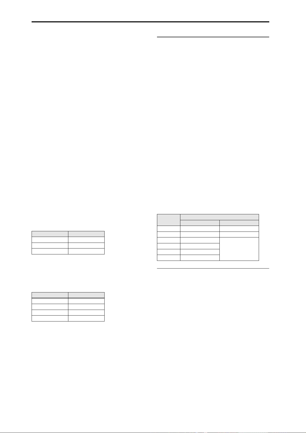
Program mode
This parameter determines what happens when more than
one note is being held down.
Low: The lowest note will sound. Many vintage,
monophonic analog synths work this way
High: The highest note will sound.
Last: The most recently played note will sound.
Unison [On, Off]
Unison can be used in Mono mode.
On (checked): When Unison is on, the Program uses two or
more stacked, detuned voices to create a thick sound.
Use the Number of Voices and Detune parameters to set the
number of voices and amount of detuning, and the
Thickness parameter to control the character of the
detuning.
Off (unchecked): The Program plays normally.
Number of Voices [2...6]
This controls the number of detuned voices that will be
played for each note when using Unison. It applies only
when Unison is On.
Detune [00...99 cents]
Detune is available when Unison is On.
This parameter sets the tuning spread for the Unison voices,
in cents (1/100 of a semitone). The Thickness parameter,
below, controls how the voices are distributed across the
detune amount. When Thickness is Off, the voices are
distributed evenly, centered around the basic pitch.
For instance, let’s say that the Number of voices parameter
is set to 3, Detune is set to 24, and Thickness is Off:
Voice one will be detuned down by 12 cents, voice two will
not be detuned, and voice three will be detuned up by 12
cents.
Voice Detune
1
2
3 +12
As another example, let’s say that Detune is still set to 24
and Thickness is still Off, but Number of voices is set to 4:
Voice one will still be detuned down by 12 cents, voice two
will be detuned down by 4 cents, voice three will be detuned
up by 4 cents, and voice 4 will be detuned up by 12 cents.
Voice Detune
1
2
3+4
4 +12
–12
0
–12
–4
1–1c: Half-Damper Control
A half-damper pedal is a special type of continuous foot
pedal, such as the Korg DS-1H. In comparison to a standard
footswitch, half-damper pedals offer more subtle control of
sustain, which can be especially useful for piano sounds.
The M50 will automatically sense when a half-damper is
connected to the rear-panel DAMPER input. For proper
operation, you will also need to calibrate the pedal, using
the Half Damper Calibration command in the Global
menu.
The off and full-on positions of the half-damper work just
like a standard footswitch. In conjunction with the Enable
Half-Damper parameter, below, intermediate positions
allow a graduated control of sustain, similar to the damper
pedal of an acoustic piano.
Enable Half-Damper [On, Off]
When this is On (checked), Half-Damper pedals, normal
sustain pedals, and MIDI CC# 64 will all modulate the Amp
EG, as described below.
When this is Off (un-checked), the pedals and MIDI CC#64
will still hold notes as usual, but will not modulate the Amp
EG.
Half-Damper Pedal and Release Time
The amount of modulation depends on whether the Amp
EG Sustain Level is set to 0 (as is the case with most acoustic
piano sounds), or set to 1 or more. The modulation is
continuous, from 1x (no change) to 55 times longer; the table
below shows a selection of representative points.
Half-Damper modulation of Amp EG Release Time
CC#64
Value
01x 1x
32 2.1x 2.1x
64 3.2x
80 5.9x
96 22.3x
127 55x
Multiply Amp EG Release Time by…
If Sustain = 0 If Sustain = 1 or more
3.2x
▼1–1: Menu Command
• 0: Write Program ☞p.73
• 1: Exclusive Solo ☞p. 73
•2: Copy Oscillator ☞p. 74
•3: Swap Oscillator ☞p. 74
For more information, please see “Program: Menu
Command” on page 73.
Thickness [Off, 01...09]
Thickness is available when Unison is On.
This parameter controls the character of the detuning for the
unison voices.
Off: Unison voices will be evenly distributed across the
Detune range, as shown above.
01–09: Unison voices will be detuned in an asymmetric way,
increasing the complexity of the detune, and changing the
way in which the different pitches beat against one another.
This creates an effect similar to vintage analog synthesizers,
in which oscillators would frequently drift slightly out of
tune. Higher numbers increase the effect.
16
Page 25

1–2: Key Zone/Scale
1–2a
PROG P1: Basic/Ctrls (Basic/Controllers) 1–2: Key Zone/Scale
you set the Oscillator Mode to Drums, it’s good to set Hold
to On.
Once you’ve turned on Hold for a drum program, the
1–2
Menu
function is controlled on a note-by-note basis according to
settings within the selected Drum Kit.
If a key’s Enable Note Off Receive parameter (Global 5–4a)
is unchecked, the note will be held.
If the key’s Enable Note Off Receive parameter is checked,
it will not be held.
If you turn off Hold in the Program, no keys will be held regardless of their Enable Note Off Receive setting.
1–2b
Here, you can make the following settings.
•Make keyboard split settings for OSC1, OSC2, and Hold.
• Select the basic scale of the program.
1–2a: Key Zone
You can create keyboard splits by setting top and bottom
key limits for Oscillators 1 and 2. Also, you can control the
keyboard range over which the Hold parameter takes effect.
Setting Key Zones from the keyboard
In addition to the usual data input methods, you can specify
the key zone values by directly playing a note on the
keyboard or by sending a MIDI note-on from an external
device.
1. Select the key zone parameter you’d like to edit.
2. While holding down the ENTER switch, play a note on
the keyboard to specify the value.
3. Release the ENTER switch.
On the M50, you can use this shortcut for parameters that
specify a key or a velocity. (Dialog boxes such as menu
commands are an exception.)
OSC 1 Bottom [C–1...G9]
This sets the lowest key on which Oscillator 1 will play.
OSC 1 Top [C–1...G9]
This sets the highest key on which Oscillator 1 will play.
OSC 2 Bottom [C–1...G9]
This sets the lowest key on which Oscillator 2 will play.
OSC 2 Top [C–1...G9]
This sets the highest key on which Oscillator 2 will play.
Hold [On, Off]
Hold is like permanently pressing down on the sustain
pedal. In other words, notes continue to sound as if you
were holding down the key - even after you lift your fingers
from the keyboard.
Unless the Sustain Level is set to 0 in Amp EG 1 (and Amp
EG 2 in a Double Program), the sound will play for the
entire length of the multisample(s).
On (checked): The Hold function is enabled for the range
set by the Hold Bottom and Hold Top parameters, below.
Off (unchecked): Notes will play normally. This is the
default setting.
Using Hold with Drum Kits
Hold can be especially useful for drum programs, since it
lets the drum samples ring out naturally. In general, when
Using Hold with Acoustic Pianos
Hold is also useful for simulating the top octaves of an
acoustic piano, in which notes always sustain until they fade
out naturally, regardless of how long you hold the key.
The Hold Bottom and Hold Top parameters are designed
for exactly this purpose. They let you limit the effect of the
Hold parameter to a specific range of the keyboard.
Hold Bottom [C–1...G9]
This sets the lowest key affected by the Hold function.
Hold Top [C–1...G9]
This sets the highest key affected by the Hold function.
1–2b: Scale
Typ e
[Equal Temperament…User Octave Scale15]
Selects the basic scale for the Program.
Note that for many of the scales, the setting of the Key
parameter, below, is very important.
Equal Temperament: This is the most widely used scale by
far, in which each semitone step is spaced at equal pitch
intervals.
Equal Temperament allows easy modulation, so that a chord
progression played in the key of C sounds roughly the same
as the same progression played in F#. Sacrificed, however, is
some of the purity of individual intervals offered by the
scales below.
Pure Major: In this temperament, major chords of the
selected key will be perfectly in tune.
Pure Minor: In this temperament, minor chords of the
selected key will be perfectly in tune.
Arabic: This scale includes the quarter-tone intervals used in
Arabic music.
Pythagoras: This scale is based on ancient Greek music
theory, and is especially effective for playing melodies. It
produces completely pure fifths, with one exception, at the
expense of detuning other intervals– thirds in particular.
As much as Pythagoras might have liked to do so, it’s not
possible to make all the fifths pure while also keeping the
octave in tune. For the sake of the octave, one of the fifths–
the interval from the sharp fourth degree to the sharp first
degree–is made quite flat.
Werkmeister (Werkmeister III): This scale was one of the
many temperament systems developed towards the end of
the Baroque period. These “Well-Tempered” tunings were
aimed at allowing relatively free transposition–although
you’ll still notice that the different keys maintain their own
distinct characteristics, unlike Equal Temperament.
J.S. Bach was referring to these new scales in his title, “The
Well-Tempered Clavier.” As such, this group are particularly
appropriate for late baroque organ and harpsichord music.
17
Page 26
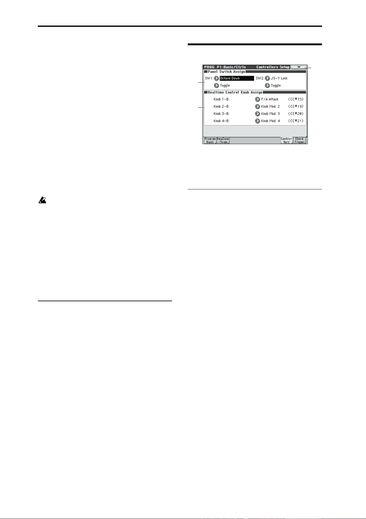
Program mode
Kirnberger (Kirnberger III): This is a second “WellTe mpered” tuning, dating from the early 18th century.
Slendro: This is an Indonesian gamelan scale, with five
notes per octave.
When Key is set to C, use the C, D, F, G and A notes. Other
keys will play the normal equal-tempered pitches.
Pelog: This is another Indonesian gamelan scale, with seven
notes per octave.
When Key is set to C, use the white keys. The black keys will
play the equal tempered pitches.
Stretch: This tuning is used for acoustic pianos.
User All Notes Scale: This is a user-programmed scale with
different settings for all 128 MIDI notes. You can set up this
scale in Global mode (Global 3–1b).
User Octave Scale 00–15: These are user-programmed scales
with settings for each of the 12 notes in an octave. You can
set them up in Global mode (Global 3–1a).
Key (Scale Key) [C…B]
Selects the key of the specified scale.
This setting does not apply to the Equal Temperament,
Stretch, and User All Notes scales.
If you’re using a scale other than Equal Temperament,
the combination of the selected scale and the Key
setting may skew the tuning of the note. For example, A
above middle C might become 442 Hz, instead of the
normal 440 Hz. You can use the Global Mode’s Master
Tune (Global 0–1a) parameter to correct this, if
necessary.
Random [0…7]
This parameter creates random variations in pitch for each
note. At the default value of 0, pitch will be completely
stable; higher values create more randomization.
This parameter is handy for simulating instruments that
have natural pitch instabilities, such as analog synths, tapemechanism organs or acoustic instruments.
▼1–2: Menu Command
• 0: Write Program ☞p.73
• 1: Exclusive Solo ☞p. 73
•2: Copy Oscillator ☞p. 74
•3: Swap Oscillator ☞p. 74
For more information, please see “Program: Menu
Command” on page 73.
1–7: Controllers Setup
1–7
Menu
1–7a
1–7b
Here you can specify the SW1 and SW2 switch and front
panel 1–4 knobs of the program when Control Assign (0–8b)
Realtime Control B mode is selected.
Note: SW1 and SW2 can be controlled by the SW1 and SW2
switches.
1–7a: Panel Switch Assign
SW (SW1 Assign) [Off, ..., JS-Y Lock]
This assigns the function of SW1. For more information,
please see “List of SW 1/2 assignments” on page 382.
Note: The on/off status of the SW1, SW2 switches is
memorized when you save the program.
If you change the function setting, the status is reset to off.
Mode (SW1 Mode) [Toggle, Momentary]
This specifies the on/off operation when you press the SW1
switch.
Toggle: The state will alternate between On and Off each
time you press the SW1 switch.
Momentary: The state will remain On only while you
continue holding down the SW1 switch.
SW2 Assign [Off, ..., JS-Y Lock]
SW2 Mode [Toggle, Momentary]
This assigns the function of SW2. The functions that can be
assigned to SW2 are the same as for SW1, with the
substitution of SW2 Mod. (CC#81) instead of the SW1’s SW1
Mod. (CC#80).
Setting the functions of SW1 and SW2
SW1 and SW2 are the two switches above the joystick.
These on/off switches can perform a number of different
functions, such as modulating sounds or effects, or locking
the modulation values of the joystick.
Also, each one may work either as a toggle, or as a
momentary switch. In Toggle mode, each press alternates
between on and off; in Momentary mode, the switch only
changes for as long as you hold it down.
Each Program, Combination, and Song stores its own
settings for what the switches will do, and whether each
switch is on or off (based on their current states when the
data is saved).
You can set up Panel Switch Assign on the Controllers Setup
page.
18
Page 27

PROG P1: Basic/Ctrls (Basic/Controllers) 1–7: Controllers Setup
Mode Page
Programs Prog P1: Basic/Ctrls
Combinations Combi P1: Controllers
Songs Seq P1: Controllers
When using SW1/2 for AMS or Dmod, the default settings
are SW1 Mod.(CC#80) and SW2 Mod.(CC#81).
For an example, see “Dynamic modulation (Dmod)” on
page 72 of the Owner’s manual.
For a complete list of the possible assignments, see “SW1/2
Assignments” on page 382.
Note: If you wish to keep these settings after the power is
turned off, you must save the Program, Combination, or
Song (see OM page 88).
1–7b: Realtime Control Knob Assign
Here you can select the functions (mainly types of control
change) that are assigned to knobs 1–4 when Control
Assign (0–8b) Realtime Control B mode is selected. (See
“Realtime Control Knobs 1–4 Assignments” on page 383)
The functions you assign here are active when you use the
CONTROL ASSIGN REALTIME CONTROL switch to select
B, and operate knobs 1–4.
Knob1–B [Off, ..., MIDI CC#95, CC#102…119]
5. Operate knob 1 to control the EG attack for the filter
and amp.
Note: If you wish to keep these settings after the power is
turned off, you must save the Program, Combination, or
Song (see OM page 88).
▼1–7: Menu Command
• 0: Write Program ☞p.73
• 1: Exclusive Solo ☞p. 73
For more information, please see “Program: Menu
Command” on page 73.
Knob2–B [Off, ..., MIDI CC#95, CC#102…119]
Knob3–B [Off, ..., MIDI CC#95, CC#102…119]
Knob4–B [Off, ..., MIDI CC#95, CC#102…119]
Setting the functions of Realtime Control B mode
knobs 1–4
When the Control Surface CONTROL ASSIGN is set to
RealTime Control B mode, the four knobs on the right
function as Realtime knobs 1–4.
These can perform a number of different functions, such as
modulating sounds or effects, adjusting effects send levels,
and so on.
Each Program, Combination, and Song stores its own
settings for what the knobs will do.
When using the sliders for AMS or Dmod, it’s important to
understand that creating an assignment is a two-step
process. First, you assign the knob to send a MIDI controller,
such as Knob Mod.1 (CC#17). Second, you assign that MIDI
controller to modulate one or more Program or effects
parameters.
For the first part of the above, use the mode’s Controllers
Setup page (See “Setting the functions of SW1 and SW2,”
above).
The default assignments for knobs 1–4 are Knob Mod.1
(CC#17), Knob Mod.2 (CC#19), Knob Mod.3 (CC#20), and
Knob Mod.4 (CC#21), respectively. For a complete list of the
possible assignments, see “Realtime Control Knobs 1–4
Assignments” on page 383.
Here’s an example of how to set up knob 1 to control a
Program’s filter and amp EG attack time:
1. Press the MODE PROG switch to enter Program mode.
2. Access the P1: Basic/Ctrls– Controllers Setup page.
Press the PAGE SELECT switch to access Page Select, and
choose “P1 Basic/Ctrls.”
3. Press the Realtime Control Knob Assign “Knob 1–B”
popup button, and choose F/A Attack (CC#73).
4. Press the CONTROL ASSIGN REALTIME CONTROL
switch to select B. (the LED B will light)
19
Page 28
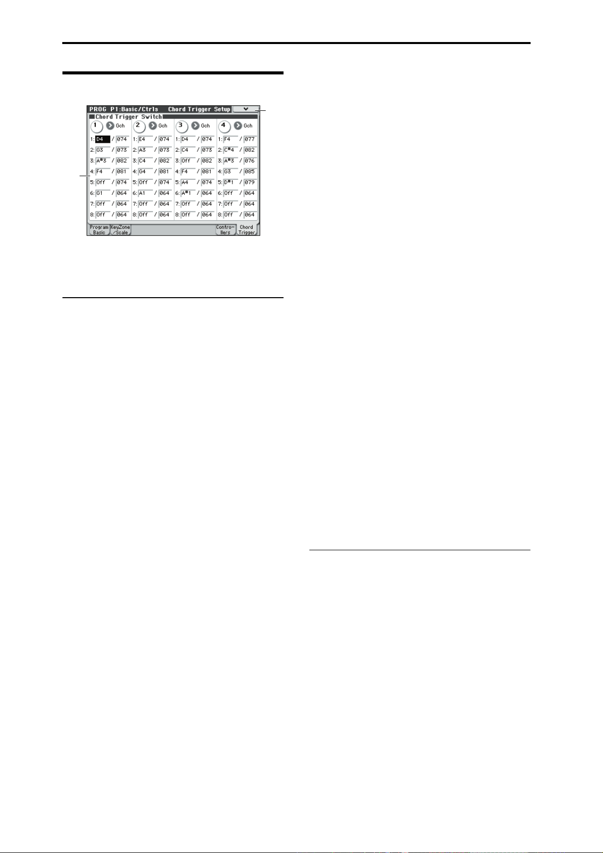
Program mode
1–8: Chord Trigger Setup
1–8
Menu
1–8a
For each program, you can assign the note numbers and
velocities that will be produced by chord trigger switches 1–
4. You can assign up to eight note numbers and their
velocity for each chord trigger switch.
1–8a: Chord Trigger Switches
SW1
MIDI Channel [Gch, Dch]
Here you can specify the MIDI channel on which the chord
trigger switch will transmit.
Gch: The switch will transmit on the global MIDI channel.
The program will sound.
Dch: The switch will transmit on the Drum Track MIDI
channel. The program of the drum track will sound.
Notes 1...8 [Off, C–1...G9 / 001...127]
These parameters let you edit the 8 notes assigned to each
chord trigger switch, along with a separate velocity for each
note. To play fewer than 8 notes, just set the unwanted notes
to Off.
Off: Select this to disable the note.
C–1…G9: This sets the note number.
001…127: This sets the note’s velocity value.
As described below, there are two ways to make these
settings.
Settings
Use either of the following two methods to assign
individual notes or chords to the chord trigger switches.
Manual settings
Specify the desired notes and velocities for the parameters
listed above.
Note: As an alternative to the automatic assignment
procedure described here, you can perform the steps in the
order of 2-1-3. However in this case, you won’t be able to
add notes one by one while holding down a note, as
described in step 2, above.
Copying notes from one chord trigger switch to
another
To copy the note assignments from one switch to another:
1. Press and release the switch whose notes you want to
copy.
2. Press the CHORD ASSIGN switch.
3. Press the switch to which you’d like to copy the notes.
The new switch will now play the same notes as the original
switch.
Merging two or more switches together
You can merge the assignments from two or more switches
together, as long as the total number of notes is 8 or fewer.
To do so:
1. Press all of the switches that you’d like to merge, and
then release them.
All of the switches must be held down at the same time.
2. Press the CHORD ASSIGN switch.
3. Press the switch to which you’d like to copy the notes.
You can even use one of the switches that was being merged,
if you like. After pressing the destination switch, you’re
done.
Performance
Press a chord trigger switch, and the assigned note numbers
and velocities will be output.
The notes will be output with the note numbers and
velocities that were assigned for each switch, regardless of
the force (velocity) with which you press the switch.
Likewise when you use CHORD ASSIGN to specify the
notes, the memorized note numbers and velocity balance
will be always reproduced.
SW 2...4
These are the same as for SW 1, as described above.
▼1–8: Menu Command
• 0: Write Program ☞p.73
• 1: Exclusive Solo ☞p. 73
• 2: Copy Chord Trigger Setup ☞p. 75
For more information, please see “Program: Menu
Command” on page 73.
Automatic settings using the [CHORD ASSIGN]
switch
Here’s how to turn CHORD ASSIGN on so that the notes
and velocity values you play on the keyboard will be
automatically assigned to the chord trigger switches.
1. Press the front panel CHORD ASSIGN switch (it will
light).
2. Play the keyboard.
If you’re unable to play all of the notes simultaneously, you
can hold down a note and add additional notes by playing
them.
3. Press the switch to which you want to assign the settings. The note numbers and velocities you played in
step 2 will automatically be assigned.
20
Page 29
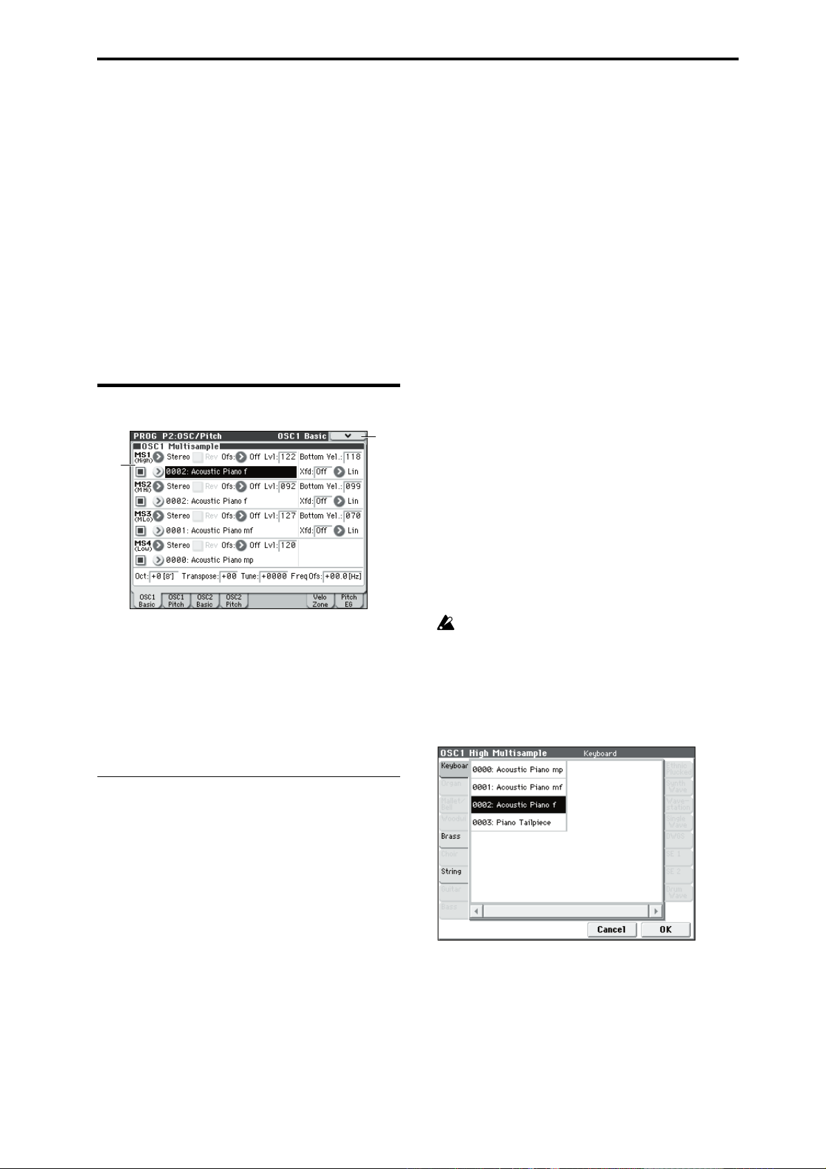
PROG P2: OSC/Pitch
PROG P2: OSC/Pitch 2–1: OSC1 Basic
These pages control the first and most basic elements of
sounds: the Multisamples that the oscillators play, and the
pitch at which it plays them. For instance, you can:
• Select Multisamples for Single and Double Programs, or
Drum Kits for Drum Programs.
• Set up velocity splits, crossfades, and layers for Single
and Double Programs.
• Set the basic pitch of the sound, including the octave,
fine tuning, and so on.
• Control pitch modulation using a variety of controllers
such as LFO, pitch EG, and the joystick.
Note that when the Oscillator Mode is set to Single or
Drums, only Oscillator 1’s filters are active; the pages for
Oscillator 2’s filters will be grayed out.
2–1: OSC1 Basic
2–1
Menu
2–1a
Each of the zones can fade into the next, to create smoother
velocity transitions. Zones can even be layered together, two
at a time.
You can stack a maximum of two velocity zones, causing
two samples to sound simultaneously (layering). You can
also use velocity to smoothly fade between the samples of
these two zones (velocity crossfading).
“Oscillator Mode” Single, Double
MS1 (High)
These are the settings for the first and highest velocity zone.
If you want to create a simple setup with only a single
Multisample, just set up MS1 as desired, and then set the
Bottom Vel. (Bottom Velocity) to 1 and the Xfd (Crossfade
Range) to Off.
Multisample On/Off [Off, On]
Specifies whether the MS1 multisample will sound.
It will sound if this is On (checked).
Bank [Mono, Stereo]
This is displayed if Multisample On/Off is On.
Yo u can choose between looking at mono and stereo
Multisamples. Note that stereo Multisamples will require
twice as many voices as mono Multisamples.
Mono: Internal monaural multisamples.
Stereo: Internal stereo multisamples.
Program’s sounds are based on multisamples, and this page
lets you set up all of the basic multisample-related settings.
Among other things, you can:
• Select Multisamples for the Oscillator (in a Single or
Double Program), or select the Drum Kit for a Drum
Program
• Set the Oscillator’s basic pitch
• Create velocity splits and crossfades between
Multisamples
2–1a: OSC1 Multisample
This setting will depend on the Oscillator Mode setting.
If it is Single or Double, each oscillator can use up to four
multisamples. In Drum mode, there is one Oscillator, and it
plays a single Drum Kit.
Multisamples, and Drum Kits
Multisamples and Drum Kits allow you to play samples in
different ways.
•Multisamples lay out one or more samples across the
keyboard. For instance, a very simple guitar
Multisample might have six samples–one for each string.
•As the name suggests, Drum Kits are optimized for
playing drum samples.
Velocity splits, crossfades, and layers
As mentioned above, unless you’re in Drum mode, each
Oscillator has four velocity zones, named MS1 (High)
through MS4 (Low). Each of these zones can play a
Multisample, and has separate settings for Level, Start
Offset, and so on.
Multisample select [List of Multisample]
This specifies a multisample for MS1.
Some multisamples have an upper limit; notes played
above that limit will not sound.
When you press the Multisample Select popup button, the
multisample list will appear, allowing you to select a
multisample from the list.
Use the tabs to select a category, and select a multisample
within the category. Press the OK button to confirm the
selection, or the Cancel button to cancel.
If Bank is set to RomM, the list shows all of the mono
Multisamples in the Bank. If the Bank contains stereo
multisamples, you’ll also see the left and right channels as
separate, mono multisamples, with –L and –R appended to
the end of the name.
If Bank is set to RomS, only stereo multisamples will be
shown.
Rev (Reverse) [Off, On]
This plays the selected multisample in reverse without
looping it.
21
Page 30
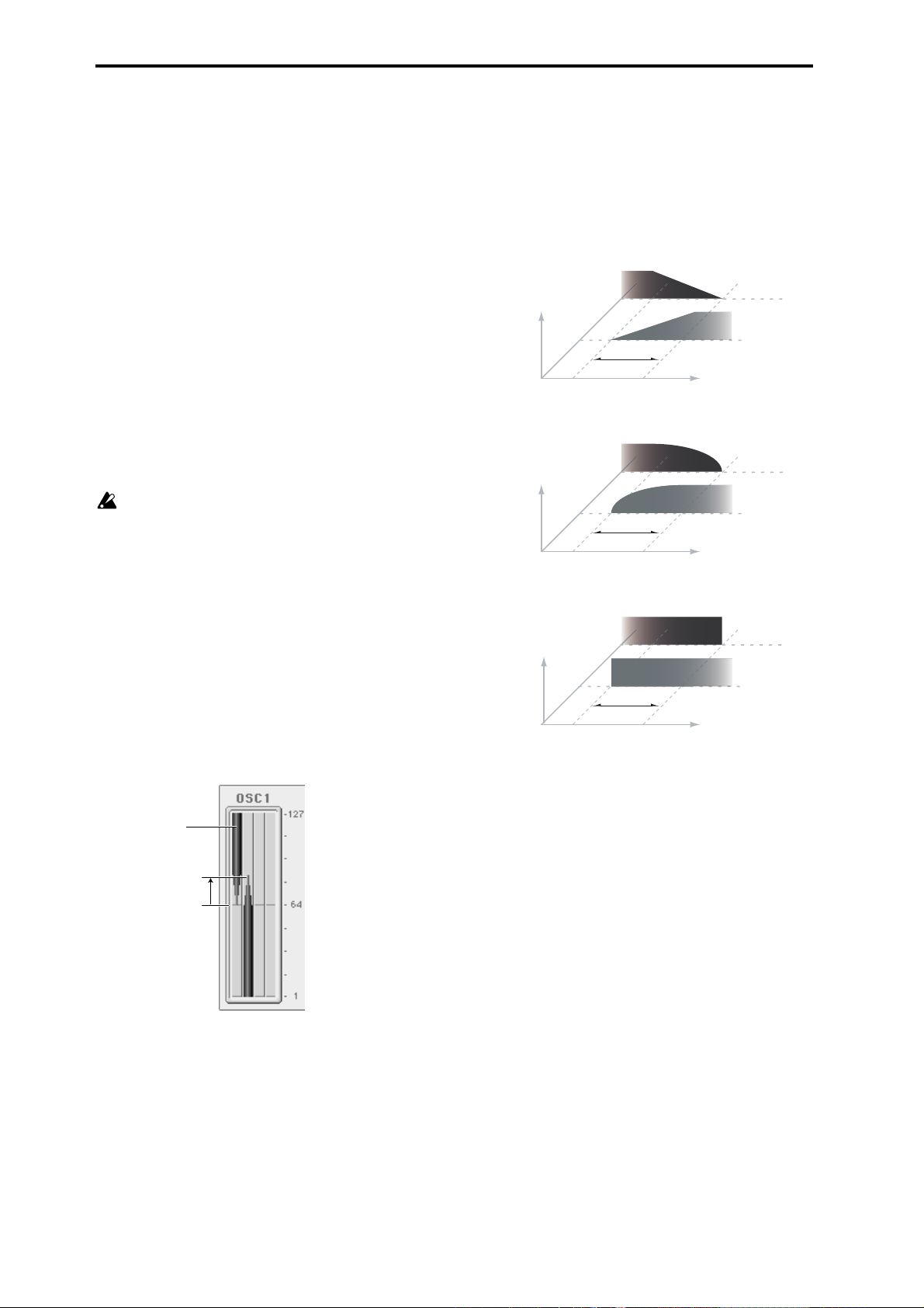
Program mode
Note: If an individual sample within the multisample is
already set to reverse, it will play in reverse without this
setting.
On (checked): The multisample will play in reverse.
Off (unchecked): The multisample will play normally.
Ofs (Start Offset) [Off, 1st...8th]
In addition to simply starting playback from the beginning,
Multisamples can have up to 8 different pre-programmed
alternate starting points.
The Start Offset specifies whether to use the normal start
point (Off), or to use one of the alternate start points (1st–
8th).
Some Multisamples may have fewer than 8 preprogrammed points, in which case only the available points
can be selected.
Lvl (Level) [000...127]
This sets the basic volume level of the multisample. The
Amp section can modify this basic level extensively with
envelopes, LFOs, keyboard tracking, and other modulation;
for more information, please see “PROG P4: Amp/EQ,” on
page 41.
Depending on the multisample, high Level settings
may cause distortion when playing many notes at a
time. If this occurs, lower the Level.
Bottom Vel. (Bottom Velocity) [001...127]
This sets the lowest velocity at which the Multisample will
sound. MS1’s Bottom Vel. can be equal to, but not lower
than, that of MS2.
Xfd (Crossfade Range) [Off, 001...127]
This sets the range of velocities over which MS1 will fade
into MS2, going up from the Bottom Vel.
For instance, if the Bottom Vel. is set to 64, and the Xfd is set
to 20, MS2 will start to fade in at velocities of 84 and below.
When velocities are within the Xfd, the Oscillator will use
twice as much polyphony as it would normally.
Note: You can only fade between two zones at once.
Select
Xfade Range = 20
Curve = Linear
Bottom Velocity = 64
84
Power, short for Equal Power, means that the two samples
will each be at around 70% of their full volume in the middle
of the crossfade. Sometimes, this may create a bump in the
volume level, in which case you might try selecting Linear
instead.
Layer means that the two Multisamples will be layered
together, both at full volume, for the entire range of the
crossfade.
Crossfade Curves
Linear
Volume
Power
Volume
Layer
Volume
MS2
MS1
Xfade
Velocity
MS2
MS1
Xfade
Velocity
MS2
MS1
Xfade
Velocity
MS2 (Mid Hi), MS3 (Mid Lo), MS4 (Low)
These are the settings for the second, third, and fourth
velocity zones. The parameters for MS2 and MS3 are exactly
the same as those for MS1, as described above.
The parameters for MS4 are also similar to those for MS1,
except that MS4 has no settings for Bottom Vel. (which is
always fixed at 1), Xfd, or Curve.
OSC1 Frequency
Curve [Linear, Power, Layer]
This controls the volume curve of the crossfade. Linear and
Power (short for Equal Power) let you fine-tune the way that
the two Multisamples mix together; one or the other may be
more appropriate for a given pair of Multisamples. Layer,
true to its name, lets you layer the two Multisamples
together without any crossfading.
Linear means that the two samples will each be at 50% of
their full volume in the middle of the crossfade. Sometimes,
this may create a dip in the volume level; if so, try using
Power instead.
22
Oct (Octave) [–2[32'], –1[16'], +0[8'], +1[4']]
This sets the basic pitch of the Oscillator, in octaves. The
default is +0[8']. The standard octave of a multisample is +0
[8'].
Transpose [–12...+12]
This adjusts the pitch in semitones, over a range of ±1
octave.
Tune [–1200...+1200]
This adjusts the pitch in cents, over a range of ±1 octave. A
cent is 1/100 of a semitone.
Freq Ofs (Frequency Offset) [–10.0Hz ... +10Hz]
This adjusts the pitch by increments of 0.1 Hz. Frequency
Offset is different from Tune in that, when used to detune
the two oscillators, it can create a constant beat frequency
across the range of the keyboard.
Page 31
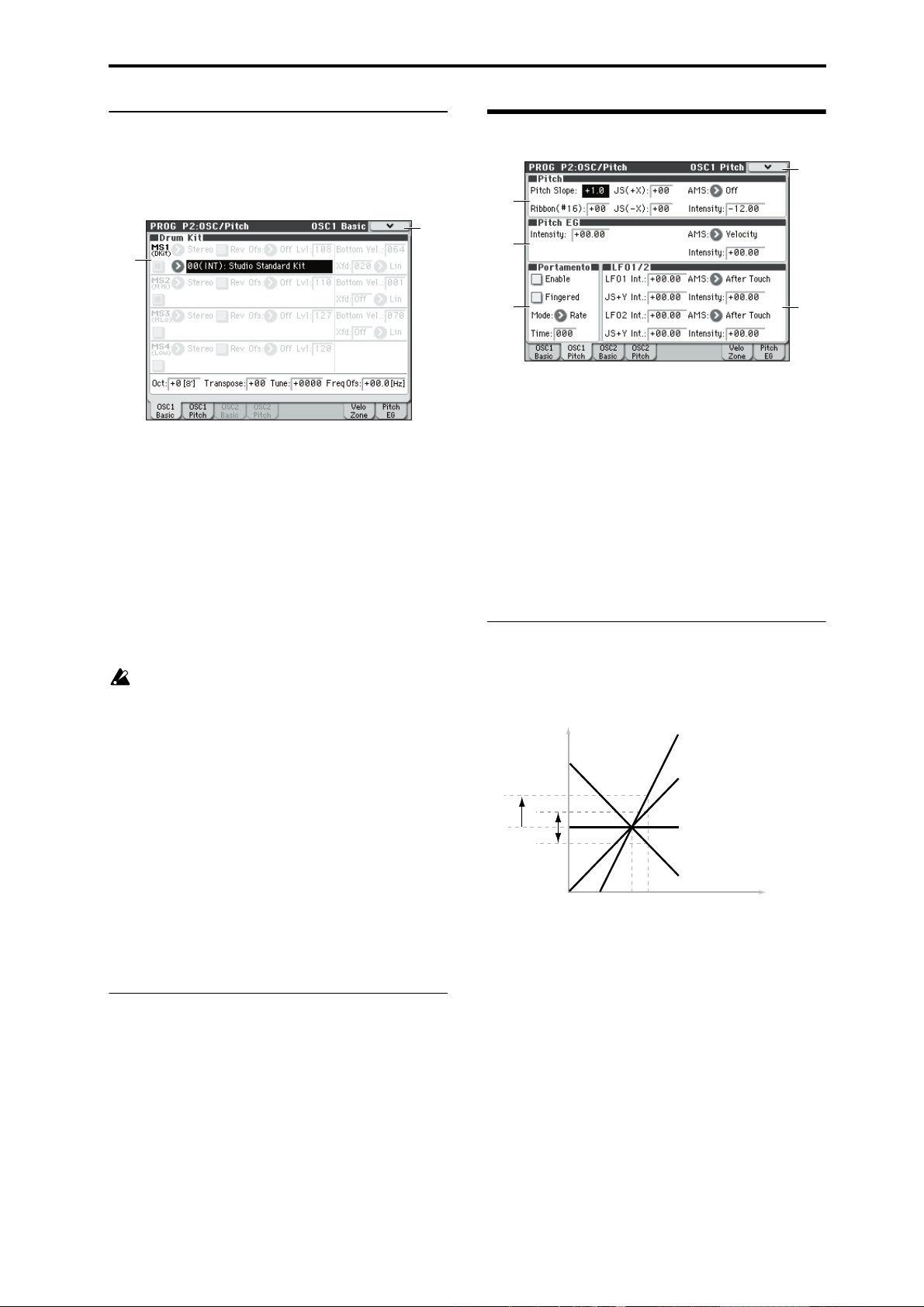
PROG P2: OSC/Pitch 2–2: OSC1 Pitch
2–1b: OSC1 Multisample
“Oscillator Mode” Drums
MS1 (DKit)
2–1
Menu
2–1b
These parameters appear when the Oscillator Mode is set to
Drum Kit.
Drum Kit [000...031 (INT), 032...047 (USER),
048…056 (GM)]
This selects a drum kit.
For 000(INT)–047(USER), you can use Global P5: Drum Kit
to edit the instrument assignments.
Drum Kit Frequency
2–2: OSC1 Pitch
2–2
Menu
2–2a
2–2b
2–2c
This page contains all of the settings for Oscillator 1’s pitch
modulation. For example, you can:
• Specify pitch bend controlled by the joystick X (or an
incoming pitch bend message) set to independent Bend
Up and Bend Down, or controlled by an incoming
message CC#16 (the ribbon control message etc).
• Use Pitch Slope to control how the pitch changes when
you play up and down the keyboard.
• Assign AMS modulation for pitch.
• Set up initial amounts of pitch modulation from the
Pitch EG and LFO1/2, as well as AMS modulation of
LFO and EG amounts.
• Set up Portamento.
2–2d
Oct (Octave) [–2[32'], –1[16'], +0[8'], +1[4']]
This adjusts the pitch in octave units. When using a drum
kit, set the Octave to 8'.
When editing a drum program, you must set this
parameter to 8'. With other settings, the sounds of the
drum kit will be assigned to the wrong notes of the
keyboard.
Transpose [–12...+12]
This adjusts the location of the instruments in the selected
drum kit. Unless you need to change this, leave it at 0.
Tune [–1200...+1200]
This adjusts the pitch in one-cent units.
The pitch of each drum kit can be adjusted in Global P5:
Drum kit.
Freq Ofs (Frequency Offset) [–10.0Hz ... +10Hz]
This adjusts the pitch by increments of 0.1 Hz. Frequency
Offset is different from Tune in that, when used to detune
the two oscillators, it can create a constant beat frequency
across the range of the keyboard.
▼2–1: Menu Command
• 0: Write Program ☞p.73
• 1: Exclusive Solo ☞p. 73
• 2: Copy Oscillator ☞p. 74
• 3: Swap Oscillator ☞p. 74
For more information, please see “Program: Menu
Command” on page 73.
2–2a: Pitch
Pitch Slope [–1.0...+2.0]
Normally, this should be set to the default of +1.0.
Pitch Slope, pitch, and note
Pitch
2oct
1oct
1oct
C4 C5
Positive (+) values cause the pitch to rise as you play higher
on the keyboard, and negative (–) values cause the pitch to
fall as you play higher on the keyboard.
When this is set to 0, playing different notes on the keyboard
won’t change the pitch at all; it will be as if you’re always
playing C4. This can be useful for special effects sounds, for
instance.
Ribbon [–12...+12]
Specify in semitones how the pitch will change when CC#16
is received.
With a positive (+) setting, the pitch will rise when the value
of CC#16 is higher than the center value of 64. With a
negative (–) setting, the pitch will fall.
+2
+1
0
–1
Note on keyboard
JS (+X) [–60...+12]
Specify in semitones how the pitch will change when the
joystick is moved to the right (or when a pitch bend message
is received). For normal pitch bend, set this to a positive
value.
23
Page 32

Program mode
For example, if you set this to +12 and move the joystick all
the way to the right, the pitch will rise one octave above the
original pitch.
JS (–X) [–60...+12]
Specify in semitones how the pitch will change when the
joystick is moved to the left (or when a pitch bend message
is received). For normal pitch bend, set this to a negative
value.
For example, if you set this to –60 and move the joystick all
the way to the left, the pitch will fall five octaves below the
original pitch. You can use this to create guitar-style
downward swoops.
AMS (Pitch) [List of AMS Sources]
This selects a AMS source to control the pitch. For a list of
AMS sources, please see “AMS (Alternate Modulation
Source) List” on page 374.
Intensity [–12.00...+12.00]
This controls the depth and direction of the pitch
modulation, in semitones.
For example if you set AMS (Pitch) to JS+Y: CC#01 and then
move the joystick in the +Y direction, the pitch will rise if
this parameter is set to a positive (+) value, or fall if this
parameter is set to a negative (–) value.
2–2b: Pitch EG
Intensity [–12.00...+12.00]
This controls the initial effect of the Pitch EG on Oscillator
1’s frequency, in half-steps, before any AMS modulation.
The Pitch EG’s shape can swing all the way from +99 to –99.
When the Intensity is set to a positive (+) value, positive
values from the EG raise the pitch, and negative values
lower the pitch.
When the Intensity is set to a negative (–) value, the effect of
the EG is reversed; positive EG values mean lower pitches,
and negative EG values mean higher pitches.
AMS (Pitch EG) [List of AMS Sources]
This selects any AMS modulation source to scale the amount
of the Pitch EG.
For a list of AMS sources, please see “AMS (Alternate
Modulation Source) List” on page 374.
Intensity [–12.00...+12.00]
This controls the depth and direction of the pitch EG AMS
modulation. The AMS modulation and the initial Intensity
are added together to determine the Pitch EG’s final effect.
With positive (+) values, greater modulation will increase
the effect of the Pitch EG, as shown in example B below.
With negative (–) values, greater modulation will introduce
the opposite effect of the Pitch EG–like inverting the polarity
of the envelope. You can use this in several different ways:
• You can set an initial positive amount with the Intensity
parameter, and then reduce this amount with AMS. In
this case, the final effect of the EG is simply diminished,
and not actually inverted, as shown in example C.
• You can also set the AMS Intensity amount to be greater
than the initial Intensity. In this case, the EG will have a
positive effect with low modulation amounts, and an
inverted effect at higher modulation amounts–as shown
in example D.
Pitch EG AMS
A. Original EG B. Intensity = +6.00
Change
to Pitch
C. Intensity = –3.00
Change
to Pitch
D. Intensity = –24.00
2–2c: Portamento
Portamento lets the pitch glide smoothly between notes,
instead of changing abruptly.
Enable [Off, On]
On (checked): Turns on Portamento, so that pitch glides
smoothly between notes.
Off (unchecked): Turns off Portamento. This is the default
state.
Fingered [Off, On]
This parameter allows you to control Portamento through
your playing style. When it’s enabled, playing legato will
turn on Portamento, and playing detached will turn it off
again.
This option is only available when Portamento Enable is
turned on.
On (checked): Turns on Fingered Portamento.
Off (unchecked): Turns off Fingered Portamento.
Mode [Rate, Time]
Rate means that Portamento will always take the same
amount of time to glide a given distance in pitch - for
instance, one second per octave. Put another way, gliding
several octaves will take much longer than gliding a halfstep.
Time means that Portamento will always take the same
amount of time to glide from one note to another, regardless
of the difference in pitch. This is especially useful when
playing chords, since it ensures that each note in the chord
will end its glide at the same time.
Time [000...127]
This controls the portamento time. Higher values mean
longer times, for slower changes in pitch.
This option is only available when Portamento Enable is
turned on.
24
Page 33

PROG P2: OSC/Pitch 2–3: OSC2 Basic
Assigning SW1 or SW2 to Portamento On/Off
You can turn portamento on/off by using the two assignable
switches SW1 and SW2.
To do so:
1. Go to the Prog P1: Basic/Ctrls– Controllers Setup page.
2. Under Panel Switch Assign, set either SW1 or SW2 to
Porta.SW (CC#65).
Now, the selected switch will enable and disable
Portamento. It will also send the MIDI Portamento
controller, CC#65.
Even if you don’t assign SW1/2 to Portamento, you can
still use MIDI Controller #65 to turn Portamento on and
off.
2–2d: LFO1/2
LFO1 and LFO2 can both control the pitch. You can control
the strength of each LFO’s modulation in three different
ways:
• Set an initial amount of LFO modulation, using the
LFO1 Int., LFO2 Int. parameters.
•Use JS +Y Int. to adjust the amount of LFO produced by
JS+Y operations.
•Use any AMS source to scale the amount of the LFO.
The results are added together to produce the total LFO
effect.
With a setting of 0, modulation will not be applied. With a
setting of 12.00, the OSC1 LFO1 will apply a maximum of
+/–1 octave of pitch modulation.
For example if AMS (LFO1) is set to JS+Y: CC#01 and you
move the joystick in the +Y direction, pitch modulation from
OSC1 LFO1 will be applied in positive phase if this is a
positive (+) value, or applied in negative phase if this is a
negative
(–) value.
LFO1 Int., JS+Y Int., and AMS (LFO1) settings are summed
to determine the depth and direction of pitch modulation
produced by OSC1 LFO1.
LFO2:
The parameters for LFO2 are identical to those for LFO1. For
more information, please see the descriptions under LFO1,
above.
▼2–2: Menu Command
• 0: Write Program ☞p.73
• 1: Exclusive Solo ☞p. 73
• 2: Copy Oscillator ☞p. 74
• 3: Swap Oscillator ☞p. 74
For more information, please see “Program: Menu
Command” on page 73.
LFO1
LFO1 Int. (LFO1 Intensity) [–12.00...+12.00]
This controls the initial effect of the LFO on the pitch, in
semitones, before any JS+Y Int. or AMS modulation.
Negative (–) settings will invert the phase of the LFO.
JS+Y Int. (LFO1 JS+Y Intensity) [–12.00...+12.00]
Specify the depth of pitch modulation produced by OSC1
LFO1 when the joystick is moved in the +Y (away) direction
(or when CC#1 is received). (Joystick control in the +Y
direction is called “JS +Y.”)
This parameter sets the maximum amount of LFO
modulation added by JS+Y, in semitones.
As this value is increased, moving the joystick in the +Y
direction will cause the OSC1 LFO1 to produce deeper pitch
modulation.
Negative (–) settings will invert the phase of the LFO. You
can also use this to reduce the initial amount of the LFO, as
set by LFO1 Int., above. For example:
1. Set LFO1 Int. to +7.00.
The LFO will now have a fairly strong effect on the pitch,
bending it by a perfect 5th.
2. Set JS+Y Int. Intensity to –7.00.
Now, if you move the joystick up, the effect of the LFO will
fade away. When the joystick is all the way at the top of its
range, the LFO will be completely cancelled out.
2–3: OSC2 Basic
This page controls the basic settings for Oscillator 2. It is
available only when the Oscillator Mode is set to Double; if
not, the page will be grayed out.
The parameters are identical to those for Oscillator 1, as
described under “2–1: OSC1 Basic,” on page 21.
2–4: OSC2 Pitch
This page controls the pitch settings for Oscillator 2. It is
available only when the Oscillator Mode is set to Double; if
not, the page will be grayed out.
The parameters are identical to those for Oscillator 1, as
described under “2–2: OSC1 Pitch,” on page 23.
AMS (LFO1) [List of AMS Sources]
This selects any AMS modulation source to scale the amount
of the LFO applied to pitch.
For a list of AMS sources, please see “AMS (Alternate
Modulation Source) List” on page 374.
Intensity [–12.00...+12.00]
This controls the depth and direction of the AMS (LFO1)
modulation for pitch.
25
Page 34
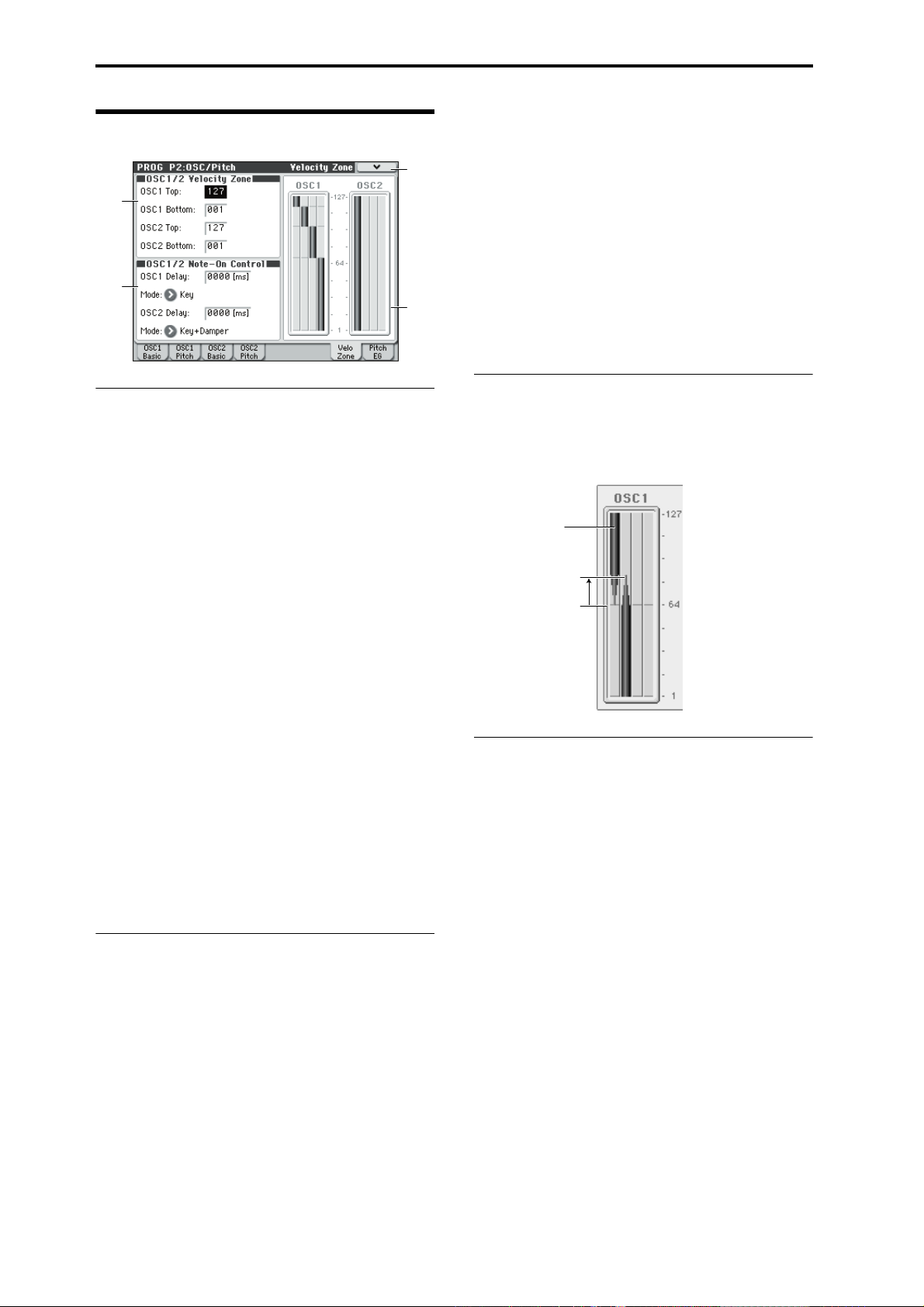
Program mode
2–7: Velocity Zone
2–7a
2–7b
2–7
Menu
2–7c
damper pedal, and then press a key, in order to play a note.
For instance, this can be useful when modeling the behavior
of a piano soundboard.
Key is the normal mode.
When you select Key + Damper, notes will only sound if the
damper pedal is being held down. When the damper pedal
is released, all notes will be stopped–even if they are still
being held down.
OSC2 Delay [0000ms...5000ms, KeyOff]
Mode [Key, Key + Damper]
This specifies the time from when you press a key until
oscillator 2 actually begins to sound.
See OSC1 Delay and Mode, above.
2–7a: OSC 1/2 Velocity Zone
You can specify the velocity zone for each of the four
multisamples of the oscillator. Here you will specify the
velocity zone for each oscillator.
These velocity zones take precedence over the velocity
settings for the individual MS1–4.
OSC1 Top [001...127]
This sets the highest velocity at which the Oscillator 1 will
sound.
Note: The OSC1 Top velocity must be greater than the
OSC1 Bottom velocity.
OSC1 Bottom [001...127]
This sets the lowest velocity at which the Oscillator 1 will
sound.
Entering velocity values from the keyboard
You can enter velocity values directly by playing them on
the keyboard. To do so:
1. Select OSC1 Top or OSC1 Bottom.
2. Hold down the ENTER switch.
3. While holding ENTER, play a note on the keyboard at
the desired velocity.
OSC2 Top [001...127]
OSC2 Bottom [001...127]
This specifies the maximum and minimum velocity values
for which oscillator 2 will sound.
See OSC1 Top and OSC1 Bottom, above.
2–7c: OSC 1/2 Velocity Zone Window
This shows the velocity zone.
This graphic reflects the OSC1 Basic and OSC2 Basic Bottom
Vel., Xfd, and Curve, and the Velocity Zone OSC1 Top,
OSC1 Bottom, OSC2 Top, and OSC2 Bottom settings.
Select
Xfade Range = 20
Curve = Linear
Bottom Velocity = 64
84
▼2–7: Menu Command
• 0: Write Program ☞p.73
• 1: Exclusive Solo ☞p. 73
• 2: Copy Oscillator ☞p. 74
• 3: Swap Oscillator ☞p. 74
For more information, please see “Program: Menu
Command” on page 73.
2–7b: OSC1/2 Note-On Control
OSC1 Delay [0000ms...5000ms, KeyOff]
This specifies the time from when you press a key until
oscillator 1 actually begins to sound.
This is most useful in Double Programs, for delaying one
oscillator in relation to the other.
KeyOff is a special setting. Instead of delaying the sound by
a particular amount of time, the sound will play as soon as
you release the key. You can use this to create the “click”
heard when a harpsichord note is released, for instance.
In general, when you use the KeyOff setting, it’s also best to
set the oscillator’s Amp EG Sustain Level to 0.
Mode [Key, Key + Damper]
Normally, you play notes simply by pressing keys on the
keyboard. In special cases, however, you can set this
parameter so that you must first be holding down the
26
Page 35
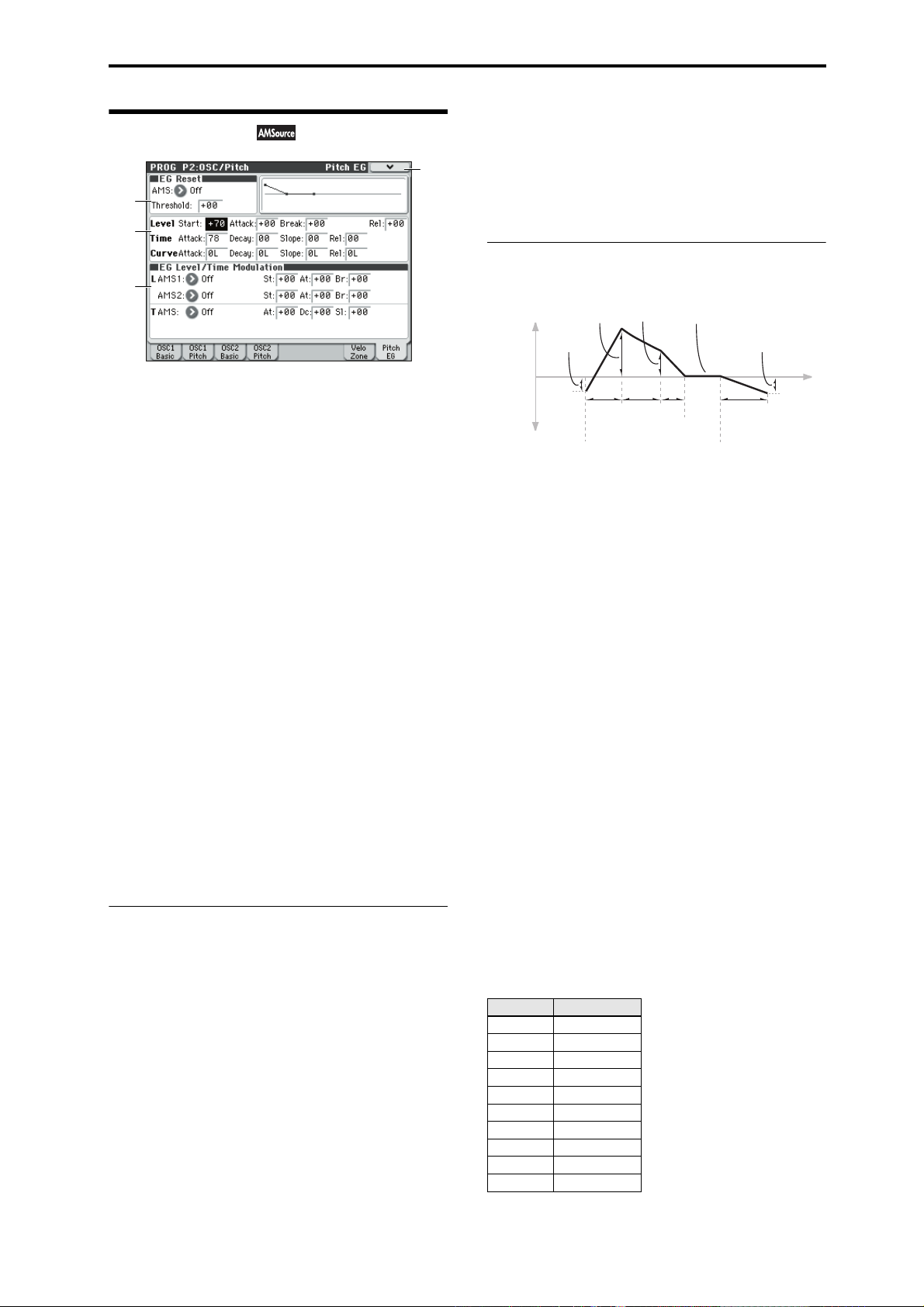
2–8: Pitch EG
2–8
Menu
2–8a
2–8b
2–8c
The Pitch EG, or Envelope Generator, lets you create
complex, time-varying changes to the pitch of Oscillators 1
and 2. The parameters on this page control the shape of the
EG. For instance, you can:
• Create the basic EG shape by setting the levels and times
of each segment.
• Control the curvature of each EG segment, for subtle
control over the modulation time of the EG.
• Set up complex modulation of EG levels and times.
• Set up an AMS source, such as an LFO, to restart the EG.
To control how much effect the EG has on the pitch, use the
Pitch EG parameters on the P2: OSC/Pitch– OSC1 Pitch
page and OSC2 Pitch page, as described under “2–2b: Pitch
EG,” on page 24.
Differences from the other EGs
The Pitch EG is different from the Filter and Amp EGs in
several ways:
• The single Pitch EG is shared by both Oscillator 1 and
Oscillator 2.
• The Sustain level is always 0.
• The Level modulation has two AMS sources instead of
one, and the Time modulation has one AMS source
instead of three.
Pitch EG is also an AMS source
You can use the Pitch EG as an AMS source to modulate
other parameters, just like the keyboard tracking and LFOs.
Simply select the Pitch EG in the AMS list for the desired
parameter.
2–8a: EG Reset
PROG P2: OSC/Pitch 2–8: Pitch EG
Note: For several LFO waveform types, or if the LFO cycle is
fast, the LFO output may not always keep up with high
values such as +99 or –99.
In this case, setting the Threshold to these values may cause
inconsistent behavior, or may mean that the EG will not
reset at all. If this happens, reduce the Threshold until the
EG triggers consistently.
2–8b: Envelope
Pitch EG
Break
Level
Decay
Time
Sustain Level
(Always 0)
Slope
Time
Note-off
Release
Time
Release
Level
Time
Change to
Pitch
Attack
Level
Start
Level
Attack
Time
Note-on or reset
The envelope moves to a specified level over the specified
time, and then moves to the next specified level over the
specified time. It produces a modulation signal
corresponding to this movement.
The parameters below let you set four levels, the amount of
time it takes to go from each of the levels to the next, and the
shape (from linear to curved) of each transition.
Level
Each of the four levels can be either positive or negative.
Positive levels will make the pitch (or other AMS
destination) go up from its programmed value; negative
levels will make it go down.
Note that, unlike the Filter and Amp EGs, the Pitch EG’s
Sustain Level is always 0.
Start [–99...+99]
This sets the initial EG level at note-on.
Attack [–99...+99]
This sets the level at the end of the Attack time.
Break [–99...+99]
Break, short for Break Point, sets the level at the end of the
Decay time.
Rel (Release) [–99...+99]
This sets the level at the end of the Release time.
AMS (EG Reset AMS) [List of AMS Sources]
This selects an AMS source to reset the EG to the start point.
For instance, you can use a tempo-synced LFO to trigger the
EG in a repeating rhythm. This reset is in addition to the
initial note-on, which always causes the EG to start.
For a list of AMS sources, please see “AMS (Alternate
Modulation Source) List” on page 374.
Threshold [–99...+99]
This sets the AMS level which will trigger the EG reset.
Among other things, you can use this to adjust the exact
point in an LFO’s phase at which the EG will be reset,
effectively controlling its “groove” against other rhythmic
effects.
When the threshold is positive, the EG triggers when
passing through the threshold moving upwards. When the
threshold is negative, the EG triggers when passing through
the threshold moving downwards.
Time
Higher values mean longer times, as shown below:
EG Value Actual Time
10 10 ms
20 44 ms
30 104 ms
40 224 ms
50 464 ms
60 944 ms
70 1.8 seconds
80 3.8 seconds
90 10.9 seconds
99 87.3 seconds
27
Page 36

Program mode
Attack [00...99]
This sets how long the EG takes to move from the Start level
to the Attack level.
For the fastest possible attack time, you can set the Start
level to +99; in this case, the EG will start instantaneously at
its maximum value.
Decay [00...99]
This sets the time it takes to move from the Attack level to
the Break level.
Slope [00...99]
This sets how long the EG takes to move from the Break
level to the Sustain level (which for the Pitch EG is always
0). Once it reaches the Sustain, the EG will stay there until
note-off, unless it is reset via AMS.
Rel (Release) [00...99]
This sets how long it takes the EG to move from the Sustain
level to the Release level.
Curve
For the sake of simplicity, most of the diagrams in this
manual show envelopes as being made out of straight lines.
In actuality, though, envelopes are more likely to be made
out of curves.
In other words, each segment’s level will change quickly at
first, and then slow down as it approaches the next point.
This tends to sound better than straight, linear segments.
Classic analog synth envelopes made these curved shapes
naturally. The M50 goes a step further than vintage synths,
however, and lets you control the amount of curvature
separately for each of the four envelope segments.
Pitch EG Curve
Slope [0L (Linear), 1...9, 10E (Exp/Log)]
This sets the curvature of the Slope segment - the transition
from the Break level to the Sustain level (which for the Pitch
EG is always 0).
Rel (Release) [0L (Linear), 1...9, 10E (Exp/Log)]
This sets the curvature of the Release segment - the
transition from the Sustain level to the Release level.
2–8c: EG Level/Time Modulation
L (Level)
These settings let you use two different AMS sources to
control the Level parameters of the EG. For each of the two
AMS sources, the Start, Attack, Decay, and Break levels each
have their own modulation intensities.
By using different settings for each of the three levels, you
can cause both subtle and dramatic changes to the EG shape,
as shown below.
Note: Once the EG has started a segment between two
points, that segment can no longer be modulated. This
includes both the time of the segment, and the level reached
at the end of the segment.
For instance, if the EG is in the middle of the Decay time,
you can no longer modulate either the Decay time or the
Break level.
This also means that modulating the Start level, Attack level,
or Attack time will not affect notes that are already
sounding, unless the EG is then re-started via EG Reset.
Pitch EG Level Modulation
Curve = 0 (Linear)
Curve = 10 (Exp/Log)
Curve = 0 (Linear)
When you change the curvature, the EG times remain the
same. However, greater curvature will tend to sound faster,
because the value changes more quickly at the beginning.
Curve = 10 (Exp/Log)
Different curve settings for up and down
You may find that different amounts of curvature are
suitable for segments which go up and segments which go
down.
For instance, a curve of 3 is a good default setting for
upward segments, such as Attack. On the other hand, a
curve of 6 or more is good for downward segments, such as
Decay and Release.
Attack [0L (Linear), 1...9, 10E (Exp/Log)]
This sets the curvature of the Attack segment - the transition
from the Start level to the Attack level.
Decay [0L (Linear), 1...9, 10E (Exp/Log)]
This sets the curvature of the Decay segment - the transition
from the Attack level to the Break level.
Original Shape
Negative AMS on Start,
Attack, and Break
Positive AMS on Start,
Attack, and Break
Positive AMS on Start and Break,
Negative AMS on Attack
AMS1
AMS1 [List of AMS Sources]
This selects the first AMS source to control the EG’s Level
parameters.
For a list of AMS sources, please see “AMS (Alternate
Modulation Source) List” on page 374.
St (Start) [–99...+99]
This controls the depth and direction of the AMS
modulation for the Start level.
For example, if you set the AMS1 source to Velocity and set
St to +99, the Start level will increase as you play harder. If
you instead set St to –99, the Start level will decrease as you
play harder.
At (Attack) [–99...+99]
This controls the depth and direction of the AMS
modulation for the Attack level.
28
Page 37

PROG P2: OSC/Pitch 2–8: Pitch EG
Br (Break) [–99...+99]
This controls the depth and direction of the AMS
modulation for the Break level.
AMS2
This selects the second AMS source for controlling the EG’s
Level parameters. The Start, Attack, Decay, and Break levels
share this source, but each has its own modulation intensity.
The parameters ofAMS2 are identical to those of AMS1,
above.
T (Time)
These settings let you use an AMS source to control the Time
parameters of the EG. The Attack, Decay, and Slope times
share this AMS source, but each has its own modulation
intensity.
Pitch EG Time Modulation
AMS=Velocity, Intensity = a positive (+) value
Note-on Note-off Note-on Note-off Note-on Note-off
“Attack”= +
“Decay”= +
“Slope”= +
Softly played note.
Original Shape.
“Attack”= +
“Decay”= +
“Slope”= +
Strongly played note.
Times are longer.
Reaches Sustain more
slowly.
“Attack”= –
“Decay”= –
“Slope”= –
Strongly played note.
Times are shorter.
Reaches Sustain more
quickly.
▼2–8: Menu Command
• 0: Write Program ☞p.73
• 1: Exclusive Solo ☞p. 73
• 2: Copy Oscillator ☞p. 74
• 3: Swap Oscillator ☞p. 74
For more information, please see “Program: Menu
Command” on page 73.
AMS
AMS [List of AMS Sources]
This selects the AMS source to control the EG’s Time
parameters. Velocity and Keyboard Track can both be useful
here, for instance.
For a list of AMS sources, please see “AMS (Alternate
Modulation Source) List” on page 374.
At (Attack) [–99...+99]
This controls the depth and direction of the AMS
modulation for the Attack time.
For example, if you set the AMS source to Velocity and set
Attack to +99, the Attack time will get much longer at higher
velocities. If you instead set Attack to –99, the Attack time
will get much shorter at higher velocities.
When the AMS source is at its maximum value–for instance,
when Velocity is at 127–a setting of +8 will make the Attack
time almost twice as long, and a setting of –8 will cut the
Attack time almost in half.
Dc (Decay) [–99...+99]
This controls the depth and direction of the AMS
modulation for the Decay time.
Sl (Slope) [–99...+99]
This controls the depth and direction of the AMS
modulation for the Slope time.
29
Page 38

Program mode
PROG P3–1: Filter1
Filtering can make subtle or dramatic changes to the
oscillator’s timbre. Each oscillator has two multimode
resonant filters, A and B, as well as a dedicated filter
envelope and keyboard tracking generator.
These pages let you control all aspects of the filters. Among
other things, you can:
•Make basic settings for each oscillator’s filters, including
routing, modes, cutoff, resonance, etc.
• Set up filter modulation, including keyboard tracking,
the filter envelope, LFO modulation, and AMS control.
Note that when the Oscillator Mode is set to Single, only
Oscillator 1’s filters are active; the pages for Oscillator 2’s
filters will be grayed out.
3–1–1: Filter1
3–1
3–1
–1a
3–1
–1b
–1
Menu
3–1
–1c
delicate resonance. Many classic analog synths used this
general type of filter.
When 24 dB/oct is selected, only the controls for Filter A are
active; the controls for Filter B will be grayed out.
Serial and Parallel Routing
Filter A (Low Pass)Oscillator Filter B (High Pass)
Filter A (Low Pass)
Oscillator
Filter B (High Pass)
This page contains all of the basic settings for Oscillator 1’s
Filter A and Filter B. For example, you can:
• Set up the filters to produce a single 12 dB/oct filter,
dual 12 dB/oct filters in either serial or parallel routing,
or a single 24 dB/oct filter.
• Set each of the two filters to Low Pass, High Pass, Band
Pass, or Band Reject modes.
• Set the cutoff, resonance, and input and output levels of
each filter, including modulation of resonance and
output level.
3–1–1a: Filter Routing
Filter Routing
[Single, Serial, Parallel, 24dB(4Pole)]
Each oscillator has two filters, Filter A and Filter B. This
parameter controls whether one or both of the filters are
used, and if both are used, it controls how they are
connected to each other.
Single. This uses only Filter A as a single 2-pole, 12 dB/
octave filter (6 dB for Band Pass and Band Reject). When this
option is selected, the controls for Filter B will be grayed out.
Serial. This uses both Filter A and Filter B. The oscillator
first goes through Filter A, and then the output of Filter A is
processed through Filter B.
Parallel. This also uses both Filter A and Filter B. The
oscillator feeds both filters directly, and the outputs of the
two filters are then summed together.
24dB/oct. This merges both filters to create a single 4-pole,
24 dB/octave filter (12 dB for Band Pass and Band Reject). In
comparison to Single, this option produces a sharper roll-off
beyond the cutoff frequency, as well as a slightly more
12db/oct / 24db/oct
Low Pass:
12dB/oct
Low Pass:
24dB/oct
3–1–1b: Filter A
Filter Type
[Low Pass (12dB/oct), High Pass (12dB/oct),
Band Pass (6dB/oct), Band Reject (6dB/oct)]
The filter will produce very different results depending on
the selected filter type. The selections will change slightly
according to the selected Filter Routing, to show the correct
cutoff slope in dB per octave.
Low Pass (12dB/oct). This cuts out the parts of the sound
which are higher than the cutoff frequency. Low Pass is the
most common type of filter, and is used to make bright
timbres sound darker.
High Pass (12dB/oct). This cuts out the parts of the sound
which are lower than the cutoff frequency. You can use this
to make timbres sound thinner or more buzzy.
Band Pass (6dB/oct). This cuts out all parts of the sound,
both highs and lows, except for the region around the cutoff
30
Page 39
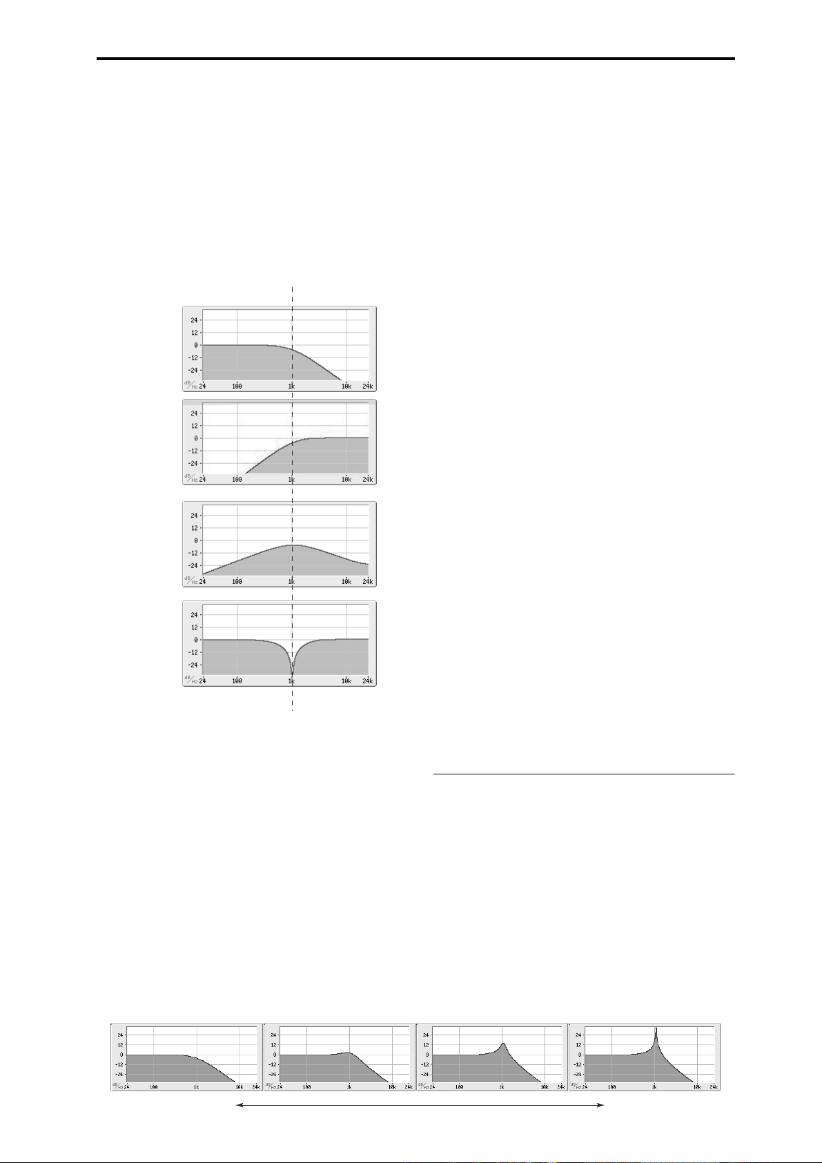
PROG P3–1: Filter1 3–1–1: Filter1
frequency. Since this filter cuts out both high and low
frequencies, its effect can change dramatically depending on
the cutoff setting and the oscillator’s multisample.
With low resonance settings, you can use the Band Pass filter
to create telephone or vintage phonograph sounds. With
higher resonance settings, it can create buzzy or nasal
timbres.
Band Reject (6dB/oct). This filter type–also called a notch
filter–cuts only the parts of the sound directly around the
cutoff frequency. Try modulating the cutoff with an LFO to
create phaser-like effects.
Filter Types and Cutoff Frequency
Low Pass
High Pass
Band Pass
Band Reject
Resonance [00...99]
Resonance emphasizes the frequencies around the cutoff
frequency.
When this is set to 0, there is no emphasis, and frequencies
beyond the cutoff will simply diminish smoothly.
At medium settings, the resonance will alter the timbre of
the filter, making it sound more nasal, or more extreme.
At very high settings, the resonance can be heard as a
separate, whistling pitch.
To make the resonance track the keyboard pitch, please see
“Key Follow,” on page 33.
AMS (Resonance) [List of AMS Sources]
This selects a AMS source to control the Resonance amount.
For a list of AMS sources, please see “AMS (Alternate
Modulation Source) List” on page 374.
AMS Int. [–99...+99]
This controls the depth and direction of the Resonance
modulation.
For example, if Velocity has been selected, changes in
keyboard velocity will affect the resonance. With positive (+)
values, the resonance will increase as you play more
strongly, and as you play more softly the resonance will
approach the level specified by the Resonance setting. With
negative (–) values, the resonance will decrease as you play
more strongly, and as you play more softly the resonance
will approach the level specified by the Resonance setting.
The resonance level is determined by adding the Resonance
and AMS Int. values.
Output [00...99]
This controls the output level of Filter A. You can use this to
balance the volumes of Filters A and B when the Routing is
set to Parallel, or to turn down the volume to avoid clipping
later in the signal chain.
AMS (Output AMS) [List of AMS Sources]
This selects a modulation source to control the output level
of Filter A. For a list of AMS sources, please see “AMS
(Alternate Modulation Source) List” on page 374.
Cutoff Frequency
Bypass [Off, On]
This lets you bypass Filter A completely.
If Bypass is Off, Filter A functions normally.
When Bypass is On, Filter A will have no effect.
Frequency [00...99]
This controls the cutoff frequency of Filter A, in increments
of 1/10 of an octave. The specific effect of the cutoff
frequency will change depending on the selected Filter
Type.
AMS Int. [–99...+99]
This controls the depth and direction of the output level
modulation.
3–1–1c: Filter B
Filter B is available when the Filter Routing is set to Serial
or Parallel. Otherwise, the parameters in this section will be
grayed out.
The parameters for Filter B are identical to those for Filter A.
For more information, please see the descriptions under
Filter A, above.
Trim [00...99]
This adjusts the volume level at the input to the filter. If you
notice that the sound is distorting, especially with high
Resonance settings, you can turn the level down here, or at
the Output.
Resonance
Low resonance value High resonance value
31
Page 40

Program mode
▼3–1–1: Menu Command
• 0: Write Program ☞p.73
• 1: Exclusive Solo ☞p. 73
• 2: Copy Oscillator ☞p. 74
• 3: Swap Oscillator ☞p. 74
For more information, please see “Program: Menu
Command” on page 73.
3–1–2: Keyboard Track
3–1
–2
Menu
3–1
–2a
This page contains the settings for Oscillator 1’s filter
keyboard track. Among other things, you can:
• Set up complex keyboard tracking shapes, and control
how the tracking affects filter cutoff.
Filter B is available when the Filter Routing is set to Serial
or Parallel. Otherwise, the parameters for Filter B will be
grayed out.
3–1–2a: Keyboard Track
Most acoustic instruments get brighter as you play higher
pitches. At its most basic, keyboard tracking re-creates this
effect by raising the lowpass filter cutoff frequency as you
play higher on the keyboard. Usually, some amount of key
tracking is necessary in order to make the timbre consistent
across the entire range.
The M50 keyboard tracking can also be much more complex,
since it allows you to create different rates of change over up
to four different parts of the keyboard. For instance, you
can:
•Make the filter cutoff increase very quickly over the
middle of the keyboard, and then open more slowly–or
not at all–in the higher octaves.
•Make the cutoff increase as you play lower on the
keyboard.
• Create abrupt changes at certain keys, for split-like
effects.
32
How it works: Keys and Ramps
The keyboard tracking works by creating four ramps, or
slopes, between five keys on the keyboard. The bottom and
top keys are fixed at the bottom and top of the MIDI range,
respectively. You can set the other three keys–named Key
Low, Center, and Key High–to be anywhere in between.
The four Ramp values control the rate of change between
each pair of keys. For instance, if the Lo Cent (Low-Center)
Ramp is set to 0, the value will stay the same between the
Key Low key and the Center key.
The Key value will be the break point, and the slope of the
lower and higher regions on the keyboard is specified by the
Ramp.
At the Center key (the main hinge), the keyboard tracking
has no effect.
Intensity to A [–99...+99]
This controls how much the keyboard tracking will affect
Filter A’s cutoff frequency. The overall effect of the Keyboard
Track is a combination of this Intensity value and the overall
Keyboard Track shape.
With positive values (+), the effect will be in the direction
specified by keyboard tracking; if the ramp goes up, the
filter cutoff will increase.
Page 41
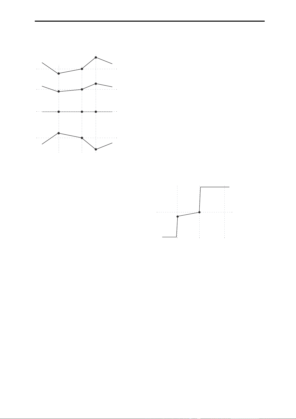
PROG P3–1: Filter1 3–1–2: Keyboard Track
Ramp = –Inf
Ramp = +Inf
Ramp = –50
Key Low Center Key High
With negative values (–), the effect will be in the opposite
direction; if the ramp goes up, the filter cutoff will decrease.
Keyboard Track Shape and Intensity
Intensity = +99 (Original Shape)
Intensity = +50 (Less Effect)
Intensity = 0 (No Effect)
Intensity = –99 (Inverted)
Low Break Key Center Key High Break Key
Intensity to B [–99...+99]
This controls how much the keyboard tracking will affect
Filter B’s cutoff frequency.
Key
When Intensity to A (B) is set to +99, a ramp of 50 changes
the filter frequency by 1 octave for every octave of the
keyboard, and a ramp of +99 changes the frequency by 2
octaves for every octave of the keyboard.
Btm Lo (Bottom-Low) [–Inf, –99...+99, +Inf]
This sets the slope between the bottom of the MIDI note
range and the Key Low key. For normal key track, use
negative values.
Lo Cent (Low-Center) [–Inf, –99...+99, +Inf]
This sets the slope between the Key Low and Center keys.
For normal key track, use negative values.
Cent Hi (Center-High) [–Inf, –99...+99, +Inf]
This sets the slope between the Center and Key High keys.
For normal key track, use positive values.
Hi Top (High-Top) [–Inf, –99...+99, +Inf]
This sets the slope between the Key High key and the top of
the MIDI note range. For normal key track, use positive
values.
+Inf and –Inf ramps
+Inf and –Inf are special settings which create abrupt
changes for split-like effects. When a ramp is set to +Inf or
–Inf, the keyboard tracking will go to its extreme highest or
lowest value over the span of a single key.
+Inf and –Inf Ramps
Key Low [C–1...G9]
This specifies the note at which the two sloped lines in the
lower range will be connected.
Center [C–1...G9]
This specifies the note that will be the break point for the
center of keyboard tracking. At this key, the keyboard
tracking has no effect on the filter cutoff, or on any AMS
destinations.
Key High [C–1...G9]
This specifies the note at which the two sloped lines in the
upper range will be connected.
Using the keyboard to enter a note value
You can press the keyboard to enter a note number directly.
1. Select one of the Key parameters.
2. Hold down the ENTER switch.
3. While holding ENTER, play a note on the keyboard.
Ramp
Positive ramp values mean that the keyboard tracking
output increases as you play farther from the Center Key;
negative ramp values mean that it decreases.
Because of this, the meanings of positive and negative ramp
settings will change depending on whether the ramp is to
the left or right of the Center Key.
Btm Lo (Bottom-Low) and Lo Cent (Low-Center): negative
ramps make the keyboard tracking’s output go down as you
play lower on the keyboard, and positive ramps make the
output go higher.
Cent Hi (Center-High) and Hi Top (High-Top): negative
ramps make the keyboard tracking’s output go down as you
play higher on the keyboard, and positive ramps make the
output go up.
The effect on the filter cutoff is a combination of the ramp
values, as set below, and the Intensity to A (B) parameters.
Note: if you set the Cent Hi ramp to +Inf or –Inf, the Hi Top
parameter will be grayed out. Similarly, if you set the Lo
Cent ramp to +Inf or –Inf, the Btm Lo ramp will be grayed
out.
Key Follow
To create the classic Key Follow effect, in which the filter
frequency tracks the pitch of the keyboard:
1. Set the Filter Frequency to 30.
2. Set the Keyboard Track Intensity to +99.
3. Set the Btm Lo and Lo Cent ramps to –50.
4. Set the Cent Hi and Hi Top ramps to +50.
5. Set the Center Key to C4.
The settings for the Key Low and Key High keys don’t
matter in this case.
Filter Keyboard Track is also an AMS source
You can use the keyboard tracking as an AMS source to
modulate other parameters, just like the envelopes and
LFOs. Simply select Filter KTrk in the AMS list for the
desired parameter.
33
Page 42

Program mode
▼3–1–2: Menu Command
• 0: Write Program ☞p.73
• 1: Exclusive Solo ☞p. 73
• 2: Copy Oscillator ☞p. 74
• 3: Swap Oscillator ☞p. 74
For more information, please see “Program: Menu
Command” on page 73.
3–1–3: Modulation
This page contains the settings for Oscillator 1’s filter
modulation. Among other things, you can:
• Control the effect of the Filter Envelope on filter cutoff.
• Assign AMS modulation for filter cutoff.
Filter B is available when the Filter Routing is set to Serial
or Parallel. Otherwise, the parameters for Filter B will be
grayed out.
3–1
–3
3–1
–3a
3–1
–3b
3–1–3a: Filter EG
The Filter EG modulates the Filter A and B cutoff
frequencies over time. You can control how strongly the EG
will affect the filters in three different ways:
• Set an initial amount of EG modulation, using the
Intensity to A and B parameters.
• Use velocity to scale the amount of the EG applied to the
filter.
• Use any AMS source to scale the amount of the EG
applied to the filter.
You can use all three of these at once, and the results are
added together to produce the total EG effect.
To set up the EG itself, including attack and release times,
levels, and so on, please see “3–1–5: EG,” on page 37.
Menu
Velocity to A [–99...+99]
This lets you use velocity to scale the amount of the Filter
EG applied to Filter A.
Velocity control of Filter EG
In all examples below, Intensity to A = +50
A. Original EG
Original
Filter Cutoff
C. Velocity to A = –25 D. Velocity to A = –99
Original
Filter Cutoff
With positive (+) values, playing more strongly will
increase the effect of the Filter EG, as shown in example B
above.
With negative (–) values, playing more strongly will
introduce the opposite effect of the Filter EG–like inverting
the polarity of the envelope. You can use this in several
different ways:
B. Velocity to A = +50
34
Page 43

PROG P3–1: Filter1 3–1–3: Modulation
• You can set an initial positive amount with the Intensity
to A/B parameters, and then reduce this amount with
velocity. In this case, the final effect of the EG is simply
diminished, and not actually inverted, as shown in
example C above.
• You can also set the Velocity to A/B amounts so that
they are greater than the initial amounts of Intensity to
A/B. In this case, the EG will have a positive effect at
low velocities, and an inverted effect at high velocities–
as shown in example D.
Velocity to B [–99...+99]
This lets you use velocity to scale the amount of the Filter
EG applied to Filter B. For more information, please see
“Velocity to A,” above.
Intensity to A [–99...+99]
This controls the initial effect of the Filter EG on Filter A’s
cutoff frequency, before any velocity or AMS modulation.
The Filter EG’s shape can swing all the way from +99 to –99.
Positive values increase the cutoff frequency, and negative
values decrease the cutoff frequency. For instance, please see
the graphic “Velocity control of Filter EG,” above. The EG
shape in example A rises up at first, and then falls below 0
towards the end.
When Intensity to A is set to a positive (+) value, the EG’s
effect will match its shape. When the EG rises above 0, the
cutoff frequency will increase.
With negative (–) values, the effect will be in the opposite
direction; when the EG rises above 0, the filter cutoff will
decrease.
AMS2 (Filter A AMS2) [List of AMS Sources]
This selects the second modulation source for controlling
Filter A’s cutoff frequency. For a list of AMS sources, please
see “AMS (Alternate Modulation Source) List” on page 374.
Intensity (AMS2 Intensity) [–99...+99]
This controls the depth and direction of AMS2.
Filter B
The parameters for Filter B are identical to those for Filter A.
For more information, please see the descriptions under
Filter A, above.
▼3–1–3: Menu Command
• 0: Write Program ☞p.73
• 1: Exclusive Solo ☞p. 73
• 2: Copy Oscillator ☞p. 74
• 3: Swap Oscillator ☞p. 74
For more information, please see “Program: Menu
Command” on page 73.
Intensity to B [–99...+99]
This controls the initial effect of the Filter EG on Filter B’s
cutoff frequency, before any velocity or AMS modulation.
For more information, please see “Intensity to A,” above.
AMS (Filter EG AMS) [List of AMS Sources]
This selects any AMS modulation source to scale the amount
of the Filter EG applied to Filters A and B. The two filters
share a single AMS source, with separate intensity settings.
Otherwise, the AMS modulation will work in the same way
as the Velocity to A parameter, described above.
For a list of AMS sources, please see “AMS (Alternate
Modulation Source) List” on page 374.
Int to A (AMS Intensity to A) [–99...+99]
This controls the depth and direction of the EG AMS
modulation for Filter A.
Int to B (AMS Intensity to B) [–99...+99]
This controls the depth and direction of the EG AMS
modulation for Filter B.
3–1–3b: Filter A/B Modulation
This section lets you assign any two AMS sources to control
Filter A, and another two AMS sources to control Filter B.
This modulation is added to the basic Filter A and B cutoff
frequencies, as set on the Filter 1 page.
Filter A
AMS1 (Filter A AMS1) [List of AMS Sources]
This selects the first modulation source for controlling Filter
A’s cutoff frequency. For a list of AMS sources, please see
“AMS (Alternate Modulation Source) List” on page 374.
Intensity (AMS1 Intensity) [–99...+99]
This controls the depth and direction of AMS1.
35
Page 44

Program mode
3–1–4: LFO Mod. (Modulation)
LFO1, LFO2, and the Common LFO can all modulate Filter
A and B’s cutoff frequencies. You can control the strength of
each LFO’s modulation independently for each filter, in
three different ways:
• Set an initial amount of LFO modulation, using the
Intensity to A and B parameters.
•Use JS-Y to scale the amount of the LFO.
•Use any AMS source to scale the amount the LFO.
You can use each of these methods for each of the three
LFOs, and do so separately for both Filter A and Filter B.
The results are added together to produce the total LFO
effect.
3–1
–4
3–1
–4a
3–1
–4b
Menu
Now, if you move the joystick down, the effect of the LFO
will fade away. When the joystick is all the way at the
bottom of its range, the LFO will be completely cancelled
out.
JS–Y Intensity to B (LFO1) [–99...+99]
This lets you use JS-Y to scale the amount of the LFO
applied to Filter B.
AMS (LFO1) [List of AMS Sources]
This selects any AMS modulation source to scale the amount
of the LFO applied to Filters A and B. The two filters share a
single AMS source, but with separate intensity settings.
For a list of AMS sources, please see “AMS (Alternate
Modulation Source) List” on page 374.
Intensity to A (LFO1) [–99...+99]
This controls the depth and direction of the LFO1 AMS
modulation for Filter A.
For example, if AMS is set to JS+Y: CC#01, positive settings
mean that YS+Y will increase the amount of LFO1 applied to
Filter A.
Intensity to B (LFO1) [–99...+99]
This controls the depth and direction of the LFO1 AMS
modulation for Filter B.
3–1–4a: LFO 1/2
LFO1
Intensity to A [–99...+99]
This controls the initial effect of the LFO on Filter A’s cutoff
frequency, before any JS-Y or AMS modulation.
Negative (–) settings will invert the phase of the LFO. You
can produce interesting effects by using the same LFO to
modulate two different parameters (such as Filter A and
Filter B), but with one set to a positive intensity, and the
other set to a negative intensity.
LFO modulation of Filter Cutoff
Low setting High setting
Intensity to B [–99...+99]
This controls the initial effect of the LFO on Filter B’s cutoff
frequency, before any JS-Y or AMS modulation.
LFO 2
The parameters for LFO2 are identical to those for LFO1. For
more information, please see the descriptions under LFO1,
above.
3–1–4b: Common LFO
The parameters for the Common LFO are identical to those
for LFO1. For more information, please see the descriptions
under LFO1, above.
Note that while LFO1 and LFO2 are separate for each voice,
the Common LFO is shared by all voices in the Program.
This makes it useful when you want all of the voices to have
an identical LFO effect.
▼3–1–4: Menu Command
• 0: Write Program ☞p.73
• 1: Exclusive Solo ☞p. 73
• 2: Copy Oscillator ☞p. 74
• 3: Swap Oscillator ☞p. 74
For more information, please see “Program: Menu
Command” on page 73.
JS–Y Intensity to A [–99...+99]
This adjusts the depth by which the LFO will modulate the
cutoff frequency of filter A when you move the joystick from
the center in the –Y direction (toward yourself) (or when
CC#2 is received). (Joystick control in the –Y direction is
called “JS –Y”.)
Negative (–) settings will invert the phase of the LFO. You
can also use this to reduce the initial amount of the LFO, as
set by Intensity to A, above. For example:
1. Set Intensity to A to +50.
The LFO will now have a fairly strong effect on the filter
cutoff.
2. Set JS-Y Intensity to A to –50.
36
Page 45

PROG P3–1: Filter1 3–1–5: EG
3–1–5: EG
3–1
–5
3–1
–5a
3–1
–5b
The Filter EG, or Envelope Generator, lets you create
complex, time-varying changes to the cutoff frequencies of
Filters A and B. The parameters on this page control the
shape of the EG. Among other things, you can:
• Create the basic EG shape by setting the levels and times
of each segment.
• Control the curvature of each EG segment, for subtle
control over the modulation shape of the EG.
• Set up complex modulation of EG levels and times.
• Set up an AMS source, such as an LFO, to restart the EG.
To control how much effect the EG has on the filters, use the
Filter EG parameters on the P3–1: Filter1– Modulation page,
as described under “3–1–3a: Filter EG,” on page 34.
Filter EG is also an AMS source
You can use the Filter EG as an AMS source to modulate
other parameters, just like the keyboard tracking and LFOs.
Simply select the Filter EG in the AMS list for the desired
parameter.
Menu
3–1–5b: Envelope
Filter EG
Break
Change to
filter cutoff
Attack
Level
Start
Level
Attack
Time
Note-on or reset
Decay
Time
Level
Slope
Time
Sustain
Level
Note-off
Release
Time
Release
Level
Time
An envelope creates a modulation signal by moving from
one level to another over a specified time, and then moving
to another level over another period of time, and so on.
The parameters below let you set five levels, the amount of
time it takes to go from each of the levels to the next, and the
shape (from linear to curved) of each transition.
Level
Each of the five levels can be either positive or negative.
Positive levels will make the cutoff frequency (or other AMS
destination) go up from its programmed value; negative
levels will make it go down.
Start [–99...+99]
This sets the initial EG level at note-on.
Attack [–99...+99]
This sets the level at the end of the Attack time.
Break [–99...+99]
Break, short for Break Point, sets the level at the end of the
Decay time.
3–1–5a: EG Reset
AMS [List of AMS Sources]
This selects an AMS source to reset the EG to the start point.
For instance, you can use a tempo-synced LFO to trigger the
EG in a repeating rhythm. This reset is in addition to the
initial note-on, which always causes the EG to start.
For a list of AMS sources, please see “AMS (Alternate
Modulation Source) List” on page 374.
Threshold [–99...+99]
This sets the AMS level which will trigger the EG reset.
Among other things, you can use this to adjust the exact
point in an LFO’s phase at which the EG will be reset,
effectively controlling its “groove” against other rhythmic
effects.
When the threshold is positive, the EG triggers when
passing through the threshold moving upwards. When the
threshold is negative, the EG triggers when passing through
the threshold moving downwards.
Note: With some LFO shapes, and with faster LFO speeds,
the LFO may not always reach the extreme values of +99 or
–99. In this case, setting the Threshold to these values may
cause inconsistent behavior, or may mean that the EG
doesn’t reset at all. If this happens, reduce the Threshold
until the EG triggers consistently.
Sus (Sustain) [–99...+99]
This sets the level at the end of the Slope time. Once it
reaches the Sustain level, the EG will stay there until noteoff, unless it is reset via AMS.
Rel (Release) [–99...+99]
This sets the level at the end of the Release time.
Time
Higher values mean longer times, as shown below:
EG Value Actual Time
10 10 ms
20 44 ms
30 104 ms
40 224 ms
50 464 ms
60 944 ms
70 1.8 seconds
80 3.8 seconds
90 10.9 seconds
99 87.3 seconds
Attack [00...99]
This sets how long the EG takes to move from the Start level
to the Attack level.
For the fastest possible attack time, you can set the Start
level to +99; in this case, the EG will start instantaneously at
its maximum value.
37
Page 46

Program mode
Decay [00...99]
This sets the time it takes to move from the Attack level to
the Break level.
Slope [00...99]
This sets how long the EG takes to move from the Break
level to the Sustain level. Once it reaches the Sustain level,
the EG will stay there until note-off (unless it is reset via
AMS).
Rel (Release) [00...99]
This sets how long it takes the EG to move from the Sustain
level to the Release level.
Curve
For the sake of simplicity, most of the diagrams in this
manual show envelopes as being made out of straight lines.
In actuality, though, envelopes are more likely to be made
out of curves.
In other words, each segment’s level will change quickly at
first, and then slow down as it approaches the next point.
This tends to sound better than straight, linear segments.
Classic analog synth envelopes made these curved shapes
naturally. The M50 goes a step further than vintage synths,
however, and lets you control the amount of curvature
separately for each of the four envelope segments.
Filter EG Curve
Curve=0L (Linear)
Curve=10E (Exp/Log)
3–1–5c: EG Level/Time Modulation
Level
These settings let you use any AMS source to control the
Level parameters of the EG. The Start, Attack, and Break
levels share a single AMS source, but can each have different
modulation intensities.
By using different settings for each of the three levels, you
can cause both subtle and dramatic changes to the EG shape,
as shown below.
Once an EG segment begins, it can’t be modulated
Once the EG has started a segment between two points, that
segment can no longer be modulated. This includes both the
time of the segment, and the level reached at the end of the
segment.
For instance, if the EG is in the middle of the Decay time,
you can no longer modulate either the Decay time or the
Break level.
As another example, let’s say that you’ve assigned the
Common LFO to modulate Break Level. The LFO may be
moving all the time, but the Break Level is only affected by
the LFO’s value at the instant that the Decay segment starts.
After that, the level is fixed.
Finally, this also means that modulating the Start level,
Attack level, or Attack time will not affect notes that are
already sounding, unless the EG is then reset via AMS.
Filter EG Level Modulation
Curve=0L (Linear)
When you change the curvature, the EG times remain the
same. However, greater curvature will tend to sound faster,
because the value changes more quickly at the beginning.
Curve=10E (Exp/Log)
Different curve settings for up and down
You may find that different amounts of curvature are
suitable for segments which go up and segments which go
down.
For instance, a curve of 3 is a good default setting for
upward segments, such as Attack. On the other hand, a
curve of 6 or more is good for downward segments, such as
Decay and Release.
Attack [0L (Linear), 1...9, 10E (Exp/Log)]
This sets the curvature of the Attack segment - the transition
from the Start level to the Attack level.
Decay [0L (Linear), 1...9, 10E (Exp/Log)]
This sets the curvature of the Decay segment - the transition
from the Attack level to the Break level.
Slope [0L (Linear), 1...9, 10E (Exp/Log)]
This sets the curvature of the Slope segment - the transition
from the Break level to the Sustain level.
Rel (Release) [0L (Linear), 1...9, 10E (Exp/Log)]
This sets the curvature of the Release segment - the
transition from the Sustain level to the Release level.
Original Shape
Negative AMS on Start,
Attack, and Break
Positive AMS on Start,
Attack, and Break
Positive AMS on Start and Break,
Negative AMS on Attack
AMS [List of AMS Sources]
Selects an AMS source to control the EG’s Level parameters.
For a list of AMS sources, please see “AMS (Alternate
Modulation Source) List” on page 374.
St (Start) [–99...+99]
This controls the depth and direction of the AMS
modulation for the Start level.
For example, if you set the AMS source to Velocity and set
St (Start) to +99, the Start level will increase as you play
harder. If you instead set St (Start) to –99, the Start level will
decrease as you play harder.
At (Attack) [–99...+99]
This controls the depth and direction of the AMS
modulation for the Attack level.
Br (Break) [–99...+99]
This controls the depth and direction of the AMS
modulation for the Break level.
38
Page 47

PROG P3–1: Filter1 3–1–5: EG
Time
These settings let you use three different AMS sources to
control the Time parameters of the EG. For each of the three
AMS sources, the Attack, Decay, Slope, and Release times
each have their own modulation intensities.
Filter EG Time Modulation
AMS=Velocity, Intensity = a positive (+) value
Note-on Note-off Note-on Note-off Note-on Note-off
“Attack”=+, “Decay”=+,
“Slope”=+, “Release”=+
Softly played note.
Original Shape
“Attack”=+, “Decay”=+,
“Slope”=+, “Release”=+
Stongly played note.
Times are longer.
Reaches Sustainmore
slowly.
AMS1 [List of AMS Sources]
Selects the first AMS source to control the EG’s Time
parameters. Velocity and Keyboard Track can both be useful
here, for instance.
For a list of AMS sources, please see “AMS (Alternate
Modulation Source) List” on page 374.
At (Attack) [–99...+99]
This controls the depth and direction of the AMS
modulation for the Attack time.
For example, if you set the AMS source to Velocity and set
At (Attack) to +99, the Attack time will get much longer at
higher velocities. If you instead set At (Attack) to –99, the
Attack time will get much shorter at higher velocities.
When the AMS source is at its maximum value–for instance,
when Velocity is at 127–a setting of +8 will make the Attack
time almost twice as long, and a setting of –8 will cut the
Attack time almost in half. (See page 379)
“Attack”=–, “Decay”=–,
“Slope”=–, “Release”=–
Stongly played note.
Times are shorter.
Reaches Sustainmore
quickly.
▼3–1–5: Menu Command
• 0: Write Program ☞p.73
• 1: Exclusive Solo ☞p. 73
• 2: Copy Oscillator ☞p. 74
• 3: Swap Oscillator ☞p. 74
•4: Sync Both EGs ☞p. 75
For more information, please see “Program: Menu
Command” on page 73.
Dc (Decay) [–99...+99]
This controls the depth and direction of the AMS
modulation for the Decay time.
Sl (Slope) [–99...+99]
This controls the depth and direction of the AMS
modulation for the Slope time.
Rl (Release) [–99...+99]
This controls the depth and direction of the AMS
modulation for the Release time.
AMS2 and AMS3
These select the second and third AMS sources, respectively,
for controlling the EG’s Time parameters. Each has its own
intensities for Attack, Decay, Slope, and Release. The
parameters of both AMS2 and AMS3 are identical to those of
AMS1, above.
39
Page 48

Program mode
PROG P3–2: Filter2
3–2–1: Filter2
This page controls Oscillator 2’s basic filter 2 settings. It is
available only when the Oscillator Mode is set to Double; if
not, the page will be grayed out.
The parameters are identical to those for Oscillator 1, as
described under “3–1–1: Filter1,” on page 30.
3–2–2: Keyboard Track
This page contains the settings for Oscillator 2’s keyboard
track. Among other things, you can:
• Set up complex keyboard tracking shapes, and control
how the tracking affects filter cutoff.
• Control the effect of the Filter Envelope on filter cutoff.
•Assign AMS modulation for filter cutoff.
Filter B is available when the Filter Routing is set to Serial
or Parallel. Otherwise, the parameters for Filter B will be
grayed out.
3–2–3: Modulation
This page controls Oscillator 2’s filter modulation. It is
available only when the Oscillator Mode is set to Double; if
not, the page will be grayed out.
The parameters are identical to those for Oscillator 1, as
described under “3–1–3: Modulation,” on page 34.
3–2–4: LFO Mod. (Modulation)
This page controls Oscillator 2’s LFO filter modulation. It is
available only when the Oscillator Mode is set to Double; if
not, the page will be grayed out.
The parameters are identical to those for Oscillator 1, as
described under “3–1–4: LFO Mod. (Modulation),” on
page 36.
3–2–5: EG
This page controls Oscillator 2’s Filter EG. It is available only
when the Oscillator Mode is set to Double; if not, the page
will be grayed out.
The parameters are identical to those for Oscillator 1, as
described under “3–1–5: EG,” on page 37.
40
Page 49

PROG P4: Amp/EQ
PROG P4: Amp/EQ 4–1: Amp1/Driver1
Oscillators 1 and 2 have separate controls for volume (also
called “amplitude,” or “amp” for short); pan; and Drive; as
well as dedicated amp envelopes and keyboard tracking
generators. Additionally, both Oscillators share a three-band
EQ.
These pages let you control all of these related parameters.
Among other things, you can:
• Set up the Driver circuit, which adds saturation and bass
boost to the timbre.
• Set the pan position and pan modulation.
• Control amp level and modulation, including keyboard
tracking, the amp envelope, LFO modulation, and AMS
control.
• Set up the three-band Track EQ.
Note that when the Oscillator Mode is set to Single, only
Oscillator 1’s amp, pan, and drive parameters are active; the
pages for Oscillator 2 will be grayed out.
4–1: Amp1/Driver1
4–1
Menu
4–1a
4–1b
Note: Even when the Drive amount is set to 0, the Driver
circuit still affects the timbre. If your goal is a completely
pristine sound, use the Bypass control instead.
AMS (Drive) [List of AMS Sources]
This selects an AMS modulation source to control the Drive
amount.
For a list of AMS sources, please see “AMS (Alternate
Modulation Source) List” on page 374.
Intensity [–99...+99]
This controls the depth and direction of the AMS
modulation for Drive.
Low Boost [00...99]
This low-frequency EQ controls the body character of the
sound. The specific EQ frequencies affected will change with
the Drive setting.
Higher amounts increase the bass boost, and will also
intensify the effect of the Drive parameter.
AMS [List of AMS Sources]
This selects an AMS modulation source to control the Low
Boost amount.
For a list of AMS sources, please see “AMS (Alternate
Modulation Source) List” on page 374.
Intensity [–99...+99]
This controls the depth and direction of the AMS
modulation for Low Boost.
4–1c
This page controls the basic settings for the Amp/EQ
section. Here, you can:
• Set up the Driver circuit.
• Set the initial volume level.
• Control the pan position and pan modulation.
4–1a: Driver
The Driver adds saturation and overdrive to the sound, for
everything from subtle fattening to drastic distortion. Unlike
an overdrive effect, the Driver processes each voice
individually, so the timbre stays the same regardless of how
many voices are being played.
The two main parameters, Drive and Low Boost, work
together to create the overall Driver effect. Drive contributes
edge and bite, and Low Boost provides the body as well as
boosting the bass.
Bypass [Off, On]
When Bypass is On, the Driver is completely removed from
the signal path.
Drive [00...99]
This controls the amount of edge and bite in the timbre. Low
settings will produce mild saturation, and higher settings
create more obvious distortion.
Often, it’s useful to increase the Low Boost along with the
Drive.
4–1b: Amp Level
Amp Level [000...127]
This controls the basic volume level of Oscillator 1, before
keyboard tracking, velocity, and other modulation.
The OSC/DrumTrk Mixer and volume
You can control the Oscillator volume directly from the
sliders in the 0–4 OSC/DrumTrk Mixer page. This is a
separate parameter, in addition to Amp Level.
MIDI and volume
You can control the Program’s overall volume via MIDI
using both Volume (CC#7) and Expression (CC#11).
When used one at a time, the two controllers work in
exactly the same way: a MIDI value of 127 is equal to
the Amp Level setting, and lower values reduce the
volume.
If both CC#7 and CC#11 are used simultaneously, the
one with the lower value determines the maximum
volume, and the one with the higher value scales down
from that maximum.
This is controlled on the global MIDI channel (Global 1–1a).
41
Page 50
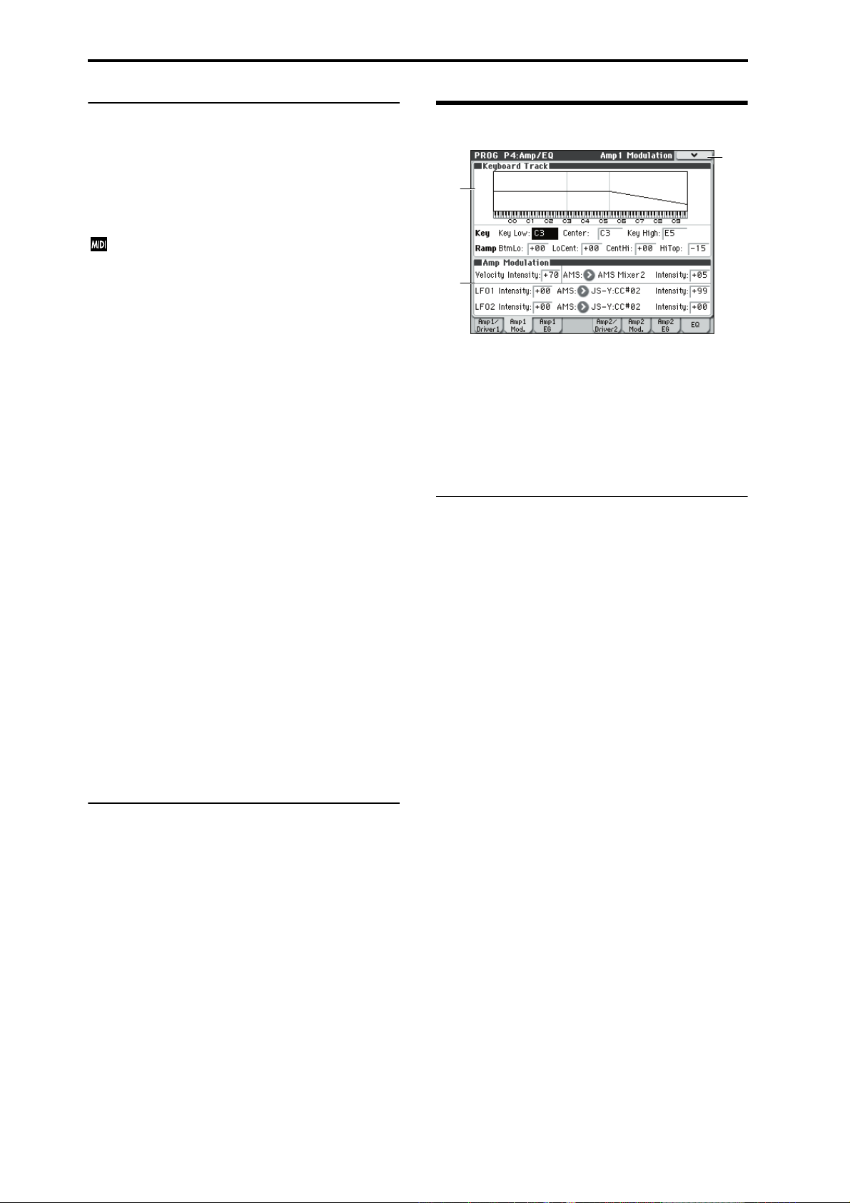
Program mode
4–1c: Pan
Pan[Random, L001...C064...R127]
This controls the stereo pan of Oscillator 1. A setting of L001
places the sound at the far left, C064 in the center, and R127
to the far right.
When this is set to Random, the pan position will be
different for each note-on.
You can also control pan via MIDI Pan (CC#10).
A CC#10 value of 0 or 1 places the sound at the far left,
64 places the sound at the location specified by the Pan
parameter, and 127 places the sound at the far right.
This is controlled on the global MIDI channel (Global 1–
1a).
Note: Random can be selected only from the display.
AMS (Pan) [List of AMS Sources]
This selects an AMS source to modulate Pan.
For a list of AMS sources, please see “AMS (Alternate
Modulation Source) List” on page 374.
Intensity [–99...+99]
This controls the depth and direction of the AMS
modulation for Pan.
For example, if Pan is set to C064 and AMS is set to Note
Number, positive (+) intensities will cause the sound to
move toward the right as you play higher than C4, and
toward the left as you play lower than C4. Negative (–)
intensities will have the opposite effect.
Use DKit Setting [Off, On]
This option is available only when the Oscillator Mode is
set to Drums.
Unlike standard Programs, Drum Kits can have a different
pan setting for every note. This parameter lets you choose
whether to use the Drum Kit pan settings, or to use the
Program’s pan setting instead.
On (checked): The Program will use the Drum Kit’s pernote pan settings; pan AMS will still apply. This is the
default setting.
Off (unchecked): The Program will ignore the Drum Kit’s
settings, and use the Program pan instead.
All keys of the drum kit will use the Pan (Global 5–4b)
setting.
▼4–1: Menu Command
• 0: Write Program ☞p.73
• 1: Exclusive Solo ☞p. 73
•2: Copy Oscillator ☞p. 74
•3: Swap Oscillator ☞p. 74
For more information, please see “Program: Menu
Command” on page 73.
4–2: Amp1 Modulation
4–2
Menu
4–2a
4–2b
This page contains the settings for Oscillator 1’s Amp level
modulation. Among other things, you can:
• Set up complex keyboard tracking shapes to control the
Amp level.
• Assign AMS modulation for the Amp level.
• Control the effect of the LFOs on the Amp level.
The total effect of the modulation can increase the volume to
a maximum of two times louder than the Amp Level setting.
4–2a: Keyboard Track
Keyboard tracking lets you vary the volume as you play up
and down the keyboard. Usually, some amount of key
tracking is necessary in order to make the volume consistent
across the entire range.
M50’s keyboard tracking can be fairly complex, if desired.
You can create different rates of change over up to four
different parts of the keyboard. For instance, you can:
•Make the volume increase very quickly over the middle
of the keyboard, and then increase more slowly–or not at
all–in the higher octaves.
•Make the volume increase as you play lower on the
keyboard.
• Create abrupt changes at certain keys, for split-like
effects.
How it works: Keys and Ramps
The keyboard tracking works by creating four ramps, or
slopes, between five keys on the keyboard. The bottom and
top keys are fixed at the bottom and top of the MIDI range,
respectively. You can set the other three keys–named Key
Low, Center, and Key High–to be anywhere in between.
The four Ramp values control the rate of change between
each pair of keys. For instance, if the Low-Center Ramp is
set to 0, the value will stay the same between the Key Low
key and the Center key.
The Key value will be the break point, and Ramp specifies
the slope of the lower region and higher region on the
keyboard.
If the Key is Center, keyboard tracking will have no effect.
42
Key:
Key Low [C–1...G9]
This specifies the note that will be the break point
connecting the two sloped lines in the low region.
Page 51

PROG P4: Amp/EQ 4–2: Amp1 Modulation
Center [C–1...G9]
This specifies the note that will be the break point in the
center of keyboard tracking. At this key, the keyboard
tracking has no effect on the volume, or on any AMS
destinations.
Key High [C–1...G9]
This specifies the note that will be the break point
connecting the two sloped lines in the high region.
Entering notes from the keyboard
You can enter velocity values directly by playing them on
the keyboard. To do so:
1. Select one of the Key parameters.
2. Hold down the ENTER switch.
3. While holding ENTER, play a note on the keyboard.
Ramp:
Positive ramp values mean that the keyboard tracking
output increases as you play farther from the Center Key;
negative ramp values mean that it decreases.
Because of this, the meanings of positive and negative ramp
settings will change depending on whether the ramp is to
the left or right of the Center Key.
Btm Lo (Bottom-Low) and Lo Cent (Low-Center): negative
ramps make the keyboard tracking’s output go down as you
play lower, and positive ramps make the output go higher.
Cent Hi (Center-High) and Hi Top (High-Top): negative
ramps make the keyboard tracking’s output go down as you
play higher, and positive ramps make the output go up.
Differences from other Keyboard Tracks
There are several differences between the Amp keyboard
tracking and the Filter and Common keyboard tracking.
For example, the results of the Ramp values are different. As
shown in the graphic “Amp Keyboard Tracking,” below,
negative slopes are more steep than positive slopes.
Also, the amp does not have separate control of Intensity.
Instead, Intensity is always fixed at the maximum amount,
allowing keyboard tracking to change the volume from
complete silence to twice as loud as the programmed level.
Btm Lo (Bottom-Low) [–Inf, –99...+99, +Inf]
This sets the slope between the bottom of the MIDI note
range and the Key Low key. For normal key track, use
negative values.
Lo Cent (Low-Center) [–Inf, –99...+99, +Inf]
This sets the slope between the Key Low and Center keys.
For normal key track, use negative values.
Cent Hi (Center-High) [–Inf, –99...+99, +Inf]
This sets the slope between the Center and Key High keys.
For normal key track, use positive values.
Hi Top (High-Top) [–Inf, –99...+99, +Inf]
This sets the slope between the Key High key and the top of
the MIDI note range. For normal key track, use positive
values.
Ramp Change in level
–Inf Silent in one half-step
–99 Silent in one whole-step
–95 Silent in one octave
–48 Silent in two octaves
–25 Silent in four octaves
00 no change
+25 x2 in four octaves
+50 x2 in two octaves
+99 x2 in one octave
+Inf x2 in one half-step
+Inf and –Inf ramps
+Inf and –Inf are special settings which create abrupt
changes for split-like effects. When a ramp is set to +Inf or
–Inf, the keyboard tracking will go to its extreme highest or
lowest value over the span of a single key.
When a ramp is set to +Inf, the keyboard tracking will go to
its highest value (double the programmed volume) over a
single half-step.
Similarly, when a ramp is set to –Inf, the keyboard tracking
will go to its lowest value (complete silence) over a single
half-step.
Note: If you set the Cent Hi (Center-High) ramp to +Inf or
–Inf, the Hi Top (High-Top) parameter will be grayed out.
Similarly, if you set the Lo Cent (Low-Center) ramp to +Inf
or –Inf, the Btm Lo (Bottom-Low) ramp will be grayed out.
Amp KTrk is also an AMS source
You can use the keyboard tracking as an AMS source to
modulate other parameters, just like the envelopes and
LFOs. Simply select Amp KTrk in the AMS list for the
desired parameter.
Amp Keyboard Tracking
Louder x2
Change to
Volume
No change
Silence
Ramp values:
Ramp values:
High Break: C4Low Break: D1 Center: G2
+99 +50 +25
–99 –97 –95 –48 –25
43
Page 52
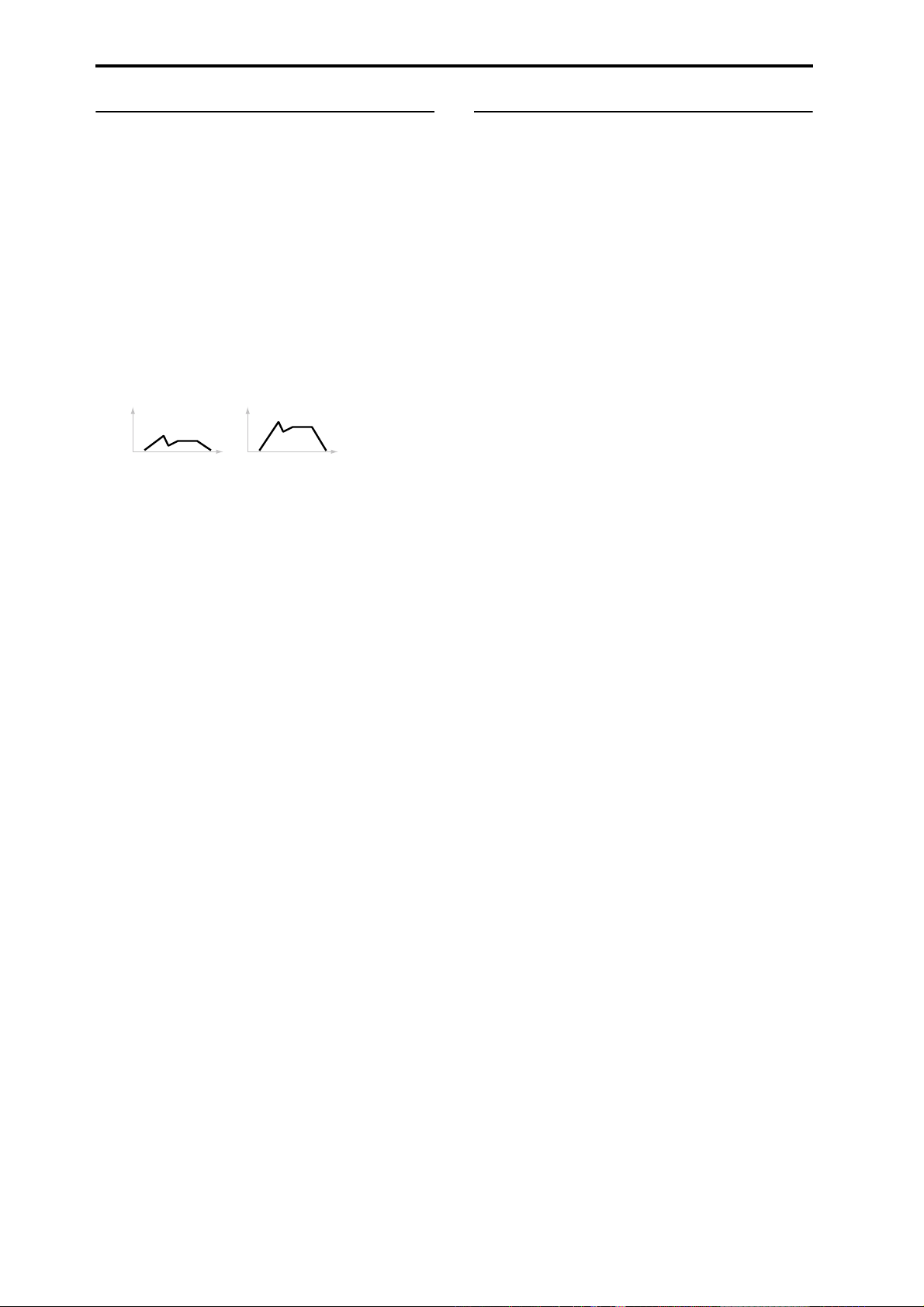
Program mode
4–2b: Amp Modulation
You can modulate the Amp level by both velocity and an
AMS source.
This modulation scales the basic Amp level and Amp EG
level parameters. The resulting volume is determined by
multiplying the volume changes of the amp EG by other
values such as AMS. If these original levels are low, the
maximum volume available with modulation will also be
reduced.
Velocity Intensity [–99...+99]
With positive (+) values, the volume will increase as you
play harder.
With negative (–) values, the volume will decrease as you
play harder.
Velocity modulation of Amp level, with Amp EG
Volume
Time
Low velocity
AMS [List of AMS Sources]
This selects any AMS modulation source to control the
Amp1 level. For a list of AMS sources, please see “AMS
(Alternate Modulation Source) List” on page 374.
Time
High velocity
▼4–2: Menu Command
• 0: Write Program ☞p.73
•1: Exclusive Solo ☞p. 73
•2: Copy Oscillator ☞p. 74
•3: Swap Oscillator ☞p. 74
For more information, please see “Program: Menu
Command” on page 73.
Intensity [–99...+99]
This controls the depth and direction of the modulation.
For example, if AMS is set to JS+Y: CC#01, positive (+)
values of this parameter will make the volume increase
when move the joystick in the +Y direction.
Note that if the other modulation settings have already
raised the volume to its maximum level (double the Amp
Level and Amp EG level settings), the volume cannot be
increased any further.
LFO 1/2
You can modulate the Amp level with both LFO1 and LFO2.
LFO1
Intensity (LFO1) [–99...+99]
This controls the depth and direction of LFO1’s effect on the
oscillator’s volume.
Negative (–) values will invert the LFO waveform.
AMS (LFO1) [List of AMS Sources]
This selects an AMS modulation source to scale the amount
of the LFO1 applied to the Amp level.
For a list of AMS sources, please see “AMS (Alternate
Modulation Source) List” on page 374.
Intensity [–99...+99]
This controls the depth and direction of the LFO1 AMS
modulation for the Amp level.
LFO2
The parameters for LFO2 are identical to those for LFO1. For
more information, please see the descriptions under LFO1,
above.
44
Page 53

4–3: Amp1 EG
4–3a
4–3b
4–3
Menu
PROG P4: Amp/EQ 4–3: Amp1 EG
Level
Start [00...99]
This sets the initial volume level at note-on.
Attack [00...99]
This sets the level at the end of the Attack time.
Break [00...99]
Break, short for Break Point, sets the level at the end of the
Decay time.
4–3c
These parameters let you create time-varying changes in the
volume of oscillator 1.
4–3a: EG Reset
AMS [List of AMS Sources]
This selects an AMS source to reset the EG to the start point.
For instance, you can use a tempo-synced LFO to trigger the
EG in a repeating rhythm. This reset is in addition to the
initial note-on, which always causes the EG to start.
For a list of AMS sources, please see “AMS (Alternate
Modulation Source) List” on page 374.
Note: Once the Amp EG is in its Release segment, it cannot
be reset. (Otherwise, the sound might keep playing forever!)
Threshold [–99...+99]
This sets the AMS level which will trigger the EG reset.
Among other things, you can use this to adjust the exact
point in an LFO’s phase at which the EG will be reset,
effectively controlling its “groove” against other rhythmic
effects. When the threshold is positive, the EG triggers when
passing through the threshold moving upwards. When the
threshold is negative, the EG triggers when passing through
the threshold moving downwards.
Note: With some LFO shapes, and with faster LFO speeds,
the LFO may not always reach the extreme values of +99 or
–99. In this case, setting the Threshold to these values may
cause inconsistent behavior, or may mean that the EG
doesn’t reset at all. If this happens, reduce the Threshold
until the EG triggers consistently.
4–3b: Envelope
These parameters specify how the amp 1 EG will change
over time.
Amp EG
Break
Volume
Attack
Start
Level
Level
Time
Attack
Note-on or reset
Time
Decay
Level
Time
Slope
Time
Sustain
Level
Note-off
Release
Time
Sus (Sustain) [00...99]
This sets the level at the end of the Slope time. Once it
reaches the Sustain level, the EG will stay there until note-off
(unless it is reset via AMS).
Time
Higher values mean longer times, as shown below.
EG Value Actual Time
10 10 ms
20 44 ms
30 104 ms
40 224 ms
50 464 ms
60 944 ms
70 1.8 seconds
80 3.8 seconds
90 10.9 seconds
99 87.3 seconds
Attack [00...99]
This sets how long the EG takes to move from the Start level
to the Attack level.
For the fastest possible attack time, you can set the Start
level to +99; in this case, the EG will start instantaneously at
its maximum value.
Decay [00...99]
This sets the time it takes to move from the Attack level to
the Break level.
Slope [00...99]
This sets how long the EG takes to move from the Break
level to the Sustain level. Once it reaches the Sustain level,
the EG will stay there until note-off (unless it is reset via
AMS).
Rel (Release) [00...99]
This sets how long it takes the EG to move from the Sustain
level to silence.
Curve
For the sake of simplicity, most of the diagrams in this
manual show envelopes as being made out of straight lines.
In actuality, though, envelopes are more likely to be made
out of curves.
In other words, each segment’s level will change quickly at
first, and then slow down as it approaches the next point.
This tends to sound better than straight, linear segments.
Classic analog synth envelopes made these curved shapes
naturally. The M50 goes a step further than vintage synths,
however, and lets you control the amount of curvature
separately for each of the four envelope segments.
When you change the curvature, the EG times remain the
same. However, greater curvature will tend to sound faster,
because the value changes more quickly at the beginning.
45
Page 54

Program mode
Amp EG Curve
Curve=0L (Linear)
Curve=10E (Exp/Log)
Curve=0L (Linear)
Curve=10E (Exp/Log)
Different curve settings for up and down
You may find that different amounts of curvature are
suitable for segments which go up and segments which go
down.
For instance, a curve of 3 is a good default setting for
upward segments, such as Attack. On the other hand, a
curve of 6 or more is good for downward segments, such as
Decay and Release.
Attack [0L (Linear), 1...9, 10E (Exp/Log)]
This sets the curvature of the Attack segment - the transition
from the Start level to the Attack level.
Decay [0L (Linear), 1...9, 10E (Exp/Log)]
This sets the curvature of the Decay segment - the transition
from the Attack level to the Break level.
Slope [0L (Linear), 1...9, 10E (Exp/Log)]
This sets the curvature of the Slope segment - the transition
from the Break level to the Sustain level.
Rel (Release) [0L (Linear), 1...9, 10E (Exp/Log)]
This sets the curvature of the Release segment - the
transition from the Sustain level to the Release level.
4–3c: EG Level/Time Modulation
Level
These settings let you use any AMS source to control the
Level parameters of the EG. The Start, Attack, and Break
levels share a single AMS source, but can each have different
modulation intensities.
By using different settings for each of the three levels, you
can cause both subtle and dramatic changes to the EG shape,
as shown below.
Once an EG segment begins, it can’t be modulated
Once the EG has started a segment between two points, that
segment can no longer be modulated. This includes both the
time of the segment, and the level reached at the end of the
segment.
For more information, please see “Once an EG segment
begins, it can’t be modulated” on page 38.
Amp EG Level Modulation
Volume
Time
Original Shape
Volume
Time
Negative AMS on Start,
Attack, and Break
Volume
Time
Positive AMS on Start,
Attack, and Break
Volume
Time
Positive AMS on Start and Break,
Negative AMS on Attack
AMS [List of AMS Sources]
This selects an AMS source to control the EG’s Level
parameters.
For a list of AMS sources, please see “AMS (Alternate
Modulation Source) List” on page 374.
St (Start) [–99...+99]
This controls the depth and direction of the AMS
modulation for the Start level.
For example, if you set the AMS source to Velocity and set St
(Start) to +99, the Start level will increase as you play harder.
If you instead set St (Start) to –99, the Start level will
decrease as you play harder.
At (Attack) [–99...+99]
This controls the depth and direction of the AMS
modulation for the Attack level.
Br (Break) [–99...+99]
This controls the depth and direction of the AMS
modulation for the Break level.
Time
These settings let you use three different AMS sources to
control the Time parameters of the EG. For each of the three
AMS sources, the Attack, Decay, Slope, and Release times
each have their own modulation intensities.
Amp EG Time Modulation
AMS=Velocity, Intensity = a positive (+) value
Note-on Note-off Note-on Note-off Note-on Note-off
“Attack”= +, “Decay”= +,
“Slope”= +, “Release”= +
Softly played note.
Original Shape.
“Attack”= +, “Decay”= +,
“Slope”= +, “Release”= +
Strongly played note.
Times are longer.
Reaches Sustain
more slowly.
AMS1 [List of AMS Sources]
Selects the first AMS source to control the EG’s Time
parameters. Velocity and Keyboard Track can both be useful
here, for instance.
For a list of AMS sources, please see “AMS (Alternate
Modulation Source) List” on page 374.
“Attack”=–, “Decay”=–,
“Slope”=–, “Release”=–
Strongly played note.
Times are shorter.
Reaches Sustain more
quickly.
46
At (Attack) [–99...+99]
This controls the depth and direction of the AMS
modulation for the Attack time.
For example, if you set the AMS source to Velocity and set
At (Attack) to +99, the Attack time will get much longer at
Page 55
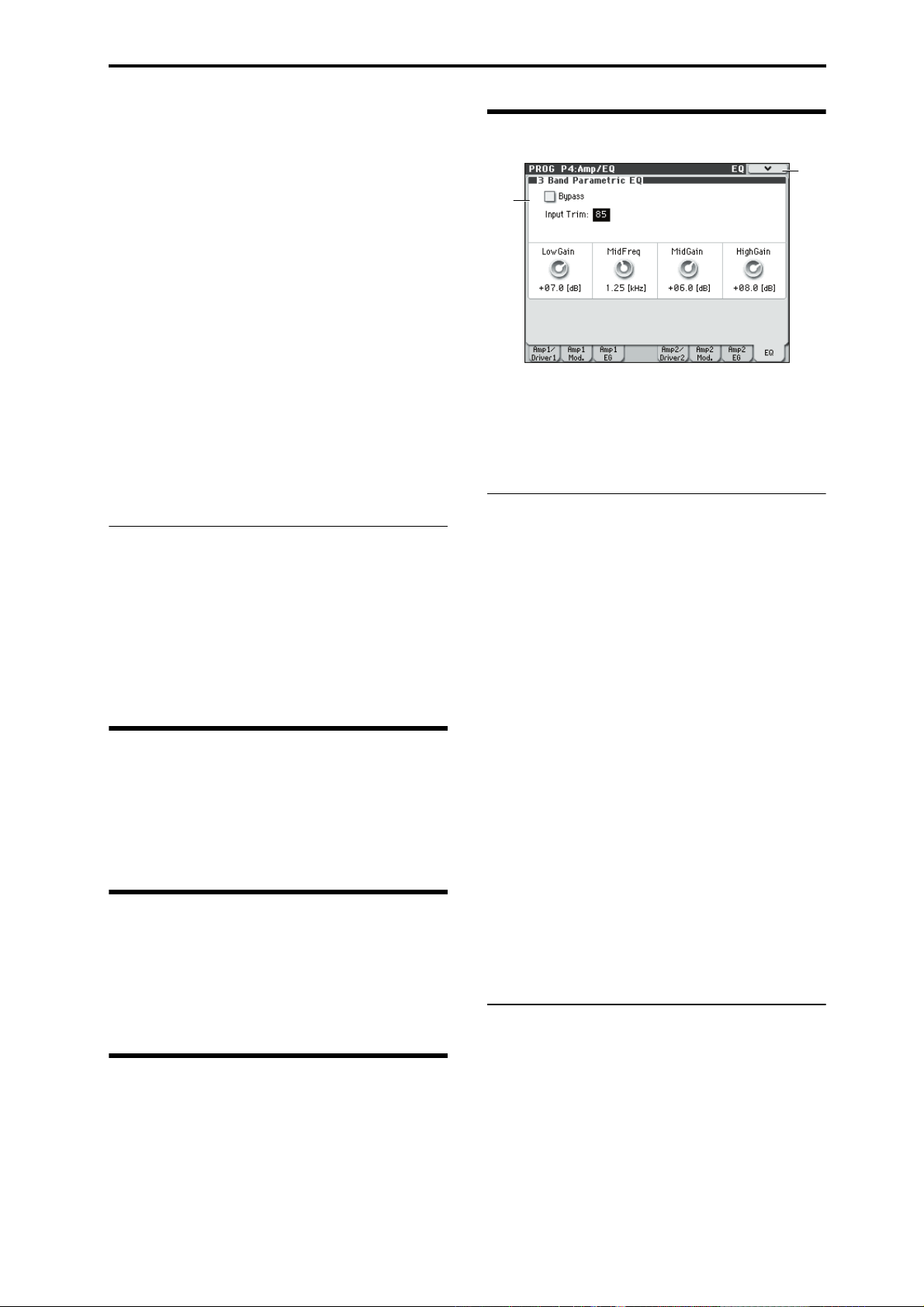
higher velocities. If you instead set At (Attack) to –99, the
Attack time will get much shorter at higher velocities.
When the AMS source is at its maximum value–for instance,
when Velocity is at 127–a setting of +8 will make the
segment time almost twice as long, and a setting of –8 will
cut the segment time almost in half.
Dc (Decay) [–99...+99]
This controls the depth and direction of the AMS
modulation for the Decay time.
Sl (Slope) [–99...+99]
This controls the depth and direction of the AMS
modulation for the Slope time.
Rl (Release) [–99...+99]
This controls the depth and direction of the AMS
modulation for the Release time.
AMS2 and AMS3
These select the second and third AMS sources, respectively,
for controlling the EG’s Time parameters. Each has its own
intensities for Attack, Decay, Slope, and Release. The
parameters of both AMS2 and AMS3 are identical to those of
AMS1, above.
PROG P4: Amp/EQ 4–5: Amp2/Driver2
4–8: EQ
4–8
Menu
4–8a
This three-band EQ, with sweepable mid, is shared by both
of the Program’s oscillators 1, 2.
In Combinations and Sequencers, each timbre and track has
its own individual EQ. You can import the Program’s EQ
settings into Tracks and Timbres by using the Combination
and Sequencer “Auto Load Program EQ” options.
4–8a: 3 Band Parametric EQ
▼4–3: Menu Command
• 0: Write Program ☞p.73
• 1: Exclusive Solo ☞p. 73
•2: Copy Oscillator ☞p. 74
•3: Swap Oscillator ☞p. 74
•4: Sync Both EGs ☞p. 75
For more information, please see “Program: Menu
Command” on page 73.
4–5: Amp2/Driver2
This page controls Oscillator 2’s basic level, pan, and driver
settings. It is available only when the Oscillator Mode is set
to Double; if not, the page will be grayed out.
The parameters are identical to those for Oscillator 1, as
described under “4–1: Amp1/Driver1,” on page 41.
4–6: Amp2 Modulation
This page controls Oscillator 2’s amp modulation. It is
available only when the Oscillator Mode is set to Double; if
not, the page will be grayed out.
The parameters are identical to those for Oscillator 1, as
described under “4–2: Amp1 Modulation,” on page 42.
4–7: Amp2 EG
This page controls Oscillator 2’s amp EG. It is available only
when the Oscillator Mode is set to Double; if not, the page
will be grayed out.
The parameters are identical to those for Oscillator 1, as
described under “4–3: Amp1 EG,” on page 45.
Bypass [On, Off]
When Bypass is checked, all of the EQ will be disabled,
including the Input Trim.
Bypass is useful for comparing the results of the EQ with the
original signal.
Input Trim [00...99]
This controls the volume level going into the EQ. The setting
corresponds to the volume; 50 corresponds to –12 dB, and 25
corresponds to –24 dB.
High settings of the Low, Mid, and High Gain controls can
cause substantial increases in the overall level. You can
compensate for this by turning down the input trim.
Low Gain [–18.0...+00.0...+18.0dB]
This controls the gain of the 80 Hz Low Shelf EQ, in
increments of 0.5 dB.
Mid Frequency [100Hz...10.00kHz]
This sets the center frequency for the Mid sweep EQ.
Mid Gain [–18.0...+00.0...+18.0dB]
This controls the gain of the Mid Sweep EQ, in increments of
0.5 dB.
High Gain [–18.0...+00.0...+18.0dB]
This controls the gain of the 10 kHz High Shelf EQ, in
increments of 0.5 dB.
▼4–8: Menu Command
• 0: Write Program ☞p.73
• 1: Exclusive Solo ☞p. 73
•2: Copy Oscillator ☞p. 74
•3: Swap Oscillator ☞p. 74
For more information, please see “Program: Menu
Command” on page 73.
47
Page 56

Program mode
PROG P5: LFO
Each of the Oscillators 1, 2 has two LFOs, which you can use
to modulate the filter, amp, pitch, and many other
parameters.
The two Oscillators also share a single Common LFO,
similar to the global LFO on some vintage analog synths.
These pages let you set up all of the parameters for all five
LFOs.
5–1: OSC1 LFO1
5–1
Menu
5–1a
5–1b
5–1c
This page has all of the controls for the first LFO of
Oscillator 1. For instance, you can:
• Select the LFO’s basic waveform, and modify it with the
Shape parameter.
• Control the LFO’s frequency, and assign AMS
controllers to modulate the frequency.
•Use the Key Sync parameter to choose whether the LFO
runs separately for each voice, or is synchronized across
all of the voices
•Use the Fade and Delay parameters to control how long
the LFO waits to start after note-on, and whether it starts
abruptly or fades in slowly.
• Set the LFO to sync to MIDI tempo.
5–1a: OSC 1 LFO 1
Waveform [Triangle...Random6 (Continuous)]
This selects the basic LFO waveform, as shown in the
graphic below.
Most of the waveforms should be self-explanatory, but a few
will benefit from more details:
Guitar is intended for guitar vibrato, and its shape is
specifically tuned for this purpose. The waveform is
positive-only, so that when used for pitch, it will only bend
up, and not down.
Random1 (S/H) generates traditional sample and hold
waveforms, in which the level changes randomly at fixed
intervals of time.
Random2 (S/H) randomizes both the levels and the timing.
Random3 (S/H) generates a pulse wave with random
timing. It’s the opposite of traditional sample and hold; the
timing varies, but the levels don’t.
Random4–6 (Continuous) are smoothed versions of
Random 1–3, with ramps instead of steps. You can use them
to create more gentle random variations.
Phase [–180...+180, Random]
This controls the phase of the waveform at the start of the
note, in steps of 5 degrees.
If Key Sync is Off, the Start Phase will apply only to the first
note of the phrase.
Freq (Frequency) [00...99]
This controls the speed of the LFO, before any modulation.
Higher values mean faster speeds, as shown in the table
below.
By using AMS modulation, you can also get speeds much
faster and much slower than are available through this basic
setting.
Frequency Value Frequency in Hz
00 0.014 Hz
10 0.112 Hz
20 0.422 Hz
30 0.979 Hz
40 1.79 Hz
50 2.84 Hz
60 4.14 Hz
70 5.69 Hz
80 7.49 Hz
90 9.53 Hz
99 26.25 Hz
99 + Fine 99 32 Hz
Stop [Off, On]
On (checked): Instead of the LFO operating normally, it will
ignore the Freq setting. The LFO will maintain the initial
value (determined by the combination of Waveform, Phase,
Shape, and Offset) until the note-off.
Since the value will change only at note-on, using a Random
waveform will produce a fixed value that changes randomly
at each note-on (or at the first note-on).
Off (unchecked): The LFO will operate normally.
Shape [–99...+99]
Shape adds curvature to the basic waveform. As you can see
in the graphic below, this can make the waveforms either
more rounded or more extreme. It can also be useful to
emphasize certain value ranges, and de-emphasize others.
For example, let’s say that you are using a triangle LFO to
modulate filter cutoff. If Shape emphasizes the high value
range, the filter will spend more time at the higher
48
LFO waveform
Triangle Step Triangle-4
Saw
Square
Sine
Guitar
Exponential
Triangle
Exponential
Saw Down
Exponential
Saw Up
Step Triangle-6
Step Saw-4
Step Saw-6
Random1
(S/H)
Random2
(S/H)
Random3
(S/H)
Random4
(Continuous)
Random5
(Continuous)
Random6
(Continuous)
Page 57

PROG P5: LFO 5–1: OSC1 LFO1
frequencies. If it emphasizes the low range, the filter will
spend more time at the lower frequencies.
LFO Shape
+99
0
–99
Shape = 0 (original waveform)
Shape = +99
Shape = –99
Note: Shape does not affect the Square and Random3
waveforms, since their values are always either +99 or –99.
When these are selected, Shape is grayed out.
AMS (Shape) [List of AMS Sources]
This selects a AMS source for controlling the LFO’s Shape.
Modulating the shape can dramatically alter the effect of the
LFO–try it out!
For a list of AMS sources, please see “AMS (Alternate
Modulation Source) List” on page 374.
AMS Int (Intensity) [–99...+99]
This controls the depth and direction of the AMS (Shape)
modulation.
Since Offset affects the output values of the LFO, it’s
important to note that it affects the signal after the Shape
function, as shown below:
How the LFO signal is affected by Shape and Offset
OffsetShapeWaveform
Fade [00...99]
The LFO can fade in gradually, instead of simply starting
immediately at full strength. This parameter specifies the
time from when the LFO begins to play until it reaches its
maximum amplitude.
If the Delay parameter is being used, then the fade will
begin after the delay is complete.
When Key Sync is Off, the fade will apply only to the first
note in the phrase.
LFO Fade and Delay
FadeDelay
Key Sync. [Off, On]
On (checked): When Key Sync is On, the LFO starts each
time you press a key, and an independent LFO runs for each
note. This is the normal setting.
Off (unchecked): When Key Sync is Off, the LFO starts
from the phase determined by the first note in the phrase, so
that the LFOs for all notes being held are synchronized
together. The Fade and Delay settings will only apply to the
first note’s LFO.
Note that even if Key Sync is Off, each note’s LFO speed
may still be different if you modulate the Frequency by note
number, velocity, key scaling, or other note-specific AMS
sources.
Offset [–99...+99]
By default, almost all of the LFO waveforms are centered
around 0, and then swing all the way from –99 to +99. This
parameter lets you shift the LFO up and down, so that–for
instance–it’s centered on 50, and then swings from –49 to
+149.
For example, let’s say that you’re using an LFO for vibrato.
If the Offset is 0, the vibrato will be centered on the note’s
original pitch, bending it both up and down.
If the Offset is +99, on the other hand, the vibrato will only
raise the pitch above the original note.
Offset settings and pitch change produced by vibrato
Offset = –99 Offset = 0 Offset = +99
Pitch
The one exception to this is the Guitar waveform, which is
designed to emulate bending a string on a guitar–so that the
pitch only goes up, and not down. Because of this, the
waveform is centered on 50, and not on 0. Of course, you
can always use a negative Offset to shift it back down below
0 again!
Note-on Note-off
Delay [00...99]
This sets the time from note-on until the LFO starts.
When Key Sync is Off, the delay applies only to the first
note of the phrase.
5–1b: Frequency Modulation
You can use two alternate modulation sources (AMS) to
adjust the speed of the LFO.
AMS1 (Frequency) [List of AMS Sources]
This selects the first AMS source for the LFO1’s frequency.
For a list of AMS sources, please see “AMS (Alternate
Modulation Source) List” on page 374.
Note that you can use LFO2 to modulate LFO1’s frequency.
Intensity [–99...+99]
This sets the initial amount of AMS1 (Frequency). The Int
Mod AMS then adds to this initial amount.
When AMS is at its maximum value (for example by moving
the joystick fully away from yourself), the AMS affects the
frequency as shown below:
Intensity Change to LFO Frequency
+99 64x
+82 32x
+66 16x
+49 8x
+33 4x
+16 2x
–16 1/2x
–33 1/4x
–49 1/8x
–66 1/16x
–82 1/32x
–99 1/64x
Faster
Slower
49
Page 58
Program mode
Int Mod AMS (Intensity Mod AMS)
[List of AMS Sources]
This selects a secondary AMS source to scale the intensity of
AMS1.
For a list of AMS sources, please see “AMS (Alternate
Modulation Source) List” on page 374.
Intensity [–99...+99]
This controls the depth and direction of the Int Mod AMS.
Even if the main AMS1 Intensity is set to 0, Int Mod AMS
can still control the final amount of AMS A over the full +/–
99 range.
For example, if AMS1 is set to the Pitch EG, and Int Mod
AMS is set to JS+Y:CC#01, positive settings mean that YS+Y
will increase the intensity of the Pitch EG modulation of
LFO Frequency.
AMS2 (Freq. AMS2) [List of AMS Sources]
This selects the second AMS source for the LFO1’s
frequency. For a list of AMS sources, please see “AMS
(Alternate Modulation Source) List” on page 374.
Intensity [–99...+99]
This controls the amount of modulation from AMS2 (Freq.
AMS2).
5–1c: Frequency MIDI/Tempo Sync.
5–2: OSC1 LFO2
This is Oscillator 1’s second LFO. Its parameters are exactly
the same as those for the first LFO, as described under “5–1:
OSC1 LFO1” on page 48–except that LFO1 cannot modulate
LFO2.
5–5: OSC2 LFO1
This page controls Oscillator 2’s first LFO. It is available only
when the Oscillator Mode is set to Double; if not, the page
will be grayed out.
The parameters are identical to those for Oscillator 1, as
described under “5–1: OSC1 LFO1” on page 48.
5–6: OSC2 LFO2
This page controls Oscillator 2’s second LFO. It is available
only when the Oscillator Mode is set to Double; if not, the
page will be grayed out.
Its parameters are exactly the same as those for the first LFO,
as described under “5–1: OSC1 LFO1” on page 48–except
that LFO1 cannot modulate LFO2.
MIDI/Tempo Sync. [Off, On]
When MIDI/Tempo Sync is On, the LFO will synchronize to
the system tempo, as set by either the Tempo knob or MIDI
Clock. The LFO speed will be controlled by the Base Note
and Times parameters, below. All settings for Frequency
and Frequency Modulation will be ignored.
When MIDI/Tempo Sync is Off, the Frequency and
Frequency Modulation settings will determine the speed of
the LFO, and the tempo settings will have no effect.
Base Note (Sync. Base Note) [ ... ]
This sets the basic speed of the LFO, relative to the system
tempo. The values range from a 32nd note to a whole note,
including triplets.
Times (Sync. Times) [01...32]
This multiplies the length of the Base Note. For instance, if
the Base Note is set to a sixteenth note, and Times is set to
03, the LFO will cycle over a dotted eighth note.
▼5–1: Menu Command
• 0: Write Program ☞p.73
• 1: Exclusive Solo ☞p. 73
•2: Swap LFO 1&2 ☞p. 75
For more information, please see “Program: Menu
Command” on page 73.
50
Page 59
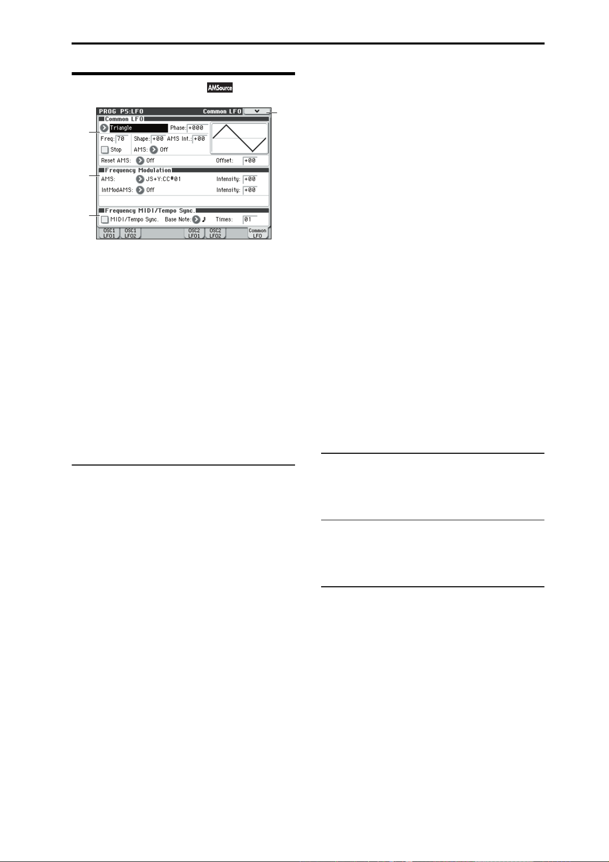
5–8: Common LFO
5–8
Menu
5–8a
5–8b
5–8c
This is a single, Common LFO, global for all voices in the
Program–like the modulation LFOs in some vintage analog
synths.
Differences from LFO1/2
The Common LFO starts running as soon as you select the
Program, and only resets when you tell it to do so explicitly
via the Reset Source control, below. This is different from
LFO1/2’s Key Sync parameter, which resets whenever all
notes are released.
The Common LFO’s persistence can be handy if you want to
create a constant rhythm with an LFO, and then play
“underneath” that rhythm without re-triggering it. For
instance, you can use a MIDI controller in your sequencer to
reset the Common LFO every few bars, regardless of what
notes are being played.
The Common LFO has most of the same controls as LFO1/2.
However, it does not include the Delay, Fade, and Key Sync
settings, since these only make sense for per-voice LFOs.
5–8a: Common LFO
Waveform [Triangle...Random6 (Continuous)]
This selects the basic LFO waveform. For a complete list of
the waveforms and more details, please see the entry under
LFO1 “Waveform,” on page 48.
Phase [–180...+180, Random]
The Reset AMS, described above, lets you reset the
Common LFO. This is the phase from which the LFO will
start when it is reset.
Freq (Frequency) [00...99]
This controls the speed of the LFO, before any modulation.
Higher values mean faster speeds. For a complete
description, please see the entry under LFO1 “Freq
(Frequency),” on page 48.
Stop [Off, On]
On (checked): Instead of the LFO operating normally, it will
ignore the Freq setting. Instead, the LFO simply generates a
single value when the Program is selected, and then holds
that value until you select another Program, or until you
reset the LFO via AMS.
Note: This is different from LFO1/2, in which the value is
reset with every note-on.
You can use this in conjunction with the Random
waveforms to create static, random modulation, with the
value changing only when you first select the Program.
Off (unchecked): When Stop is Off, the LFO will function
normally.
PROG P5: LFO 5–8: Common LFO
Shape [–99...+99]
Shape adds curvature to the basic waveform. For more
details, please see the entry under LFO1 “Shape,” on
page 48.
Note: Shape does not affect the Square and Random3
waveforms, since their values are always either +99 or –99.
AMS (Shape) [List of AMS Sources]
This selects a AMS source for controlling the LFO’s Shape.
Modulating the shape can dramatically alter the effect of the
LFO–try it out!
For a list of AMS sources, please see “AMS (Alternate
Modulation Source) List” on page 374.
AMS Int (AMS Intensity) [–99...+99]
This controls the depth and direction of the AMS (Shape)
modulation.
Reset AMS [List of AMS Sources]
This selects an AMS source to reset the LFO to the Start
Phase. The LFO resets when the AMS value passes the
halfway mark: +50 for most AMS sources, or 64 for MIDI
controllers.
To create an effect similar to the per-voice LFO’s Key Sync.
setting, set this to Gate 2+ Damper.
Offset [–99...+99]
By default, almost all of the LFO waveforms are centered
around 0, and then swing all the way from –99 to +99. This
parameter lets you shift the LFO up and down, so that–for
instance–it’s centered on 50, and then swings from –49 to
+149.
For a complete description, please see the entry under LFO1
“Offset,” on page 49.
5–8b: Frequency Modulation
These parameters are identical to the Frequency Modulation
settings for LFO1, as described under “5–1b: Frequency
Modulation,” on page 49.
5–8c: Frequency MIDI/Tempo Sync
These parameters are identical to the Frequency MIDI/
Te mpo Sync for LFO1, as described under “5–1c: Frequency
MIDI/Tempo Sync.,” on page 50.
▼5–8: Menu Command
• 0: Write Program ☞p.73
• 1: Exclusive Solo ☞p. 73
• 2: Swap LFO 1&2 ☞p. 75
For more information, please see “Program: Menu
Command” on page 73.
51
Page 60

Program mode
PROG P6: AMS/C.KTrk (AMS Mixer/Common Keyboard Track)
Each Oscillator has two AMS Mixers, which are simple but
powerful tools for combining and modifying AMS signals.
The two Oscillators also share two Common keyboard
tracking generators, in addition to the dedicated keyboard
tracking for the Filter and Amp.
These pages let you control all of these modulation sources.
Note that when the Oscillator Mode is set to Single, only
Oscillator 1’s AMS Mixers are active; the pages for Oscillator
2 will be grayed out.
6–1: OSC1 AMS Mix1
6–1
Menu
6–1a
6–1b
The AMS Mixers combine two AMS sources into one, or
process an AMS source to make it into something new.
For instance, they can add two AMS sources together, or use
one AMS source to scale the amount of another. You can also
use them to change the shapes of LFOs and EGs in various
ways, modify the response of realtime controllers, and more.
You can select the output of the AMS mixers as an AMS
source in the same way as an LFO or EQ.
This also means that the original, unmodified inputs to the
AMS Mixers are still available as well. For instance, if you
use LFO1 as an input to an AMS Mixer, you can use the
processed version of the LFO to control one AMS
destination, and the original version to control another.
Finally, you can cascade the two AMS Mixers together, by
using AMS Mixer 1 as an input to AMS Mixer 2.
LFO. For more information, please see “Smoothing” on
page 54.
Shape adds curvature to the AMS input. For more
information, please see “Shape” on page 54.
Quantize turns smooth transitions into discrete steps. For
more information, please see “Quantize” on page 55.
Gate Control uses a third AMS source to switch between
two AMS inputs (or a fixed value). For more information,
please see “Gate Control” on page 55.
A+B
AMS Mixer, Type = A+B
Amt A
AMS A
Output
AMS B
Amt B
A+B merges two AMS sources into one. This can be handy
when you need to add one more modulation source to a
parameter, but you’ve already used up all of the available
AMS slots.
For instance, let’s say that you’re using an LFO to modulate
Filter Resonance, and then you decide that it would be
interesting to scale that parameter with an EG as well.
Resonance has only a single AMS input, but you can easily
merge the LFO and the EG together using the A+B AMS
Mixer:
1. Assign the LFO to AMS A.
2. Assign the EG to AMS B.
3. Assign the AMS Mixer as the Filter Resonance AMS
source.
AMS Mixer A+B example
AMS A: LFO
6–1a: AMS Mixer 1
Mixer Type [A+B, Amt AxB, Offset, Smoothing,
Shape, Quantize, Gate Control]
This controls the type of processing performed by AMS
Mixer 1. Each of the Mixer Types is discussed in detail over
the next several pages.
A+B adds two AMS sources together. For more information,
please see “A+B” on page 52.
Amt Ax B scales the amount of one AMS source with the
other. For more information, please see “Amt AxB” on
page 53.
Offset adds or subtracts a constant value to or from an AMS
source. For more information, please see “Offset” on
page 53.
Smoothing specifies the smoothness of movement between
two values. You can use this to smooth sudden changes such
as an abrupt movement of the joystick or sharp angle of the
52
AMS B: EG
A+B Output
AMS A [List of AMS Sources]
This selects the first AMS input.
For a list of AMS sources, please see “AMS (Alternate
Modulation Source) List” on page 374.
AMS A Amount [–99...+99]
This controls the depth and direction of the AMS A input.
AMS B [List of AMS Sources]
This selects the second AMS input.
Page 61

PROG P6: AMS/C.KTrk (AMS Mixer/Common Keyboard Track) 6–1: OSC1 AMS Mix1
For a list of AMS sources, please see “AMS (Alternate
Modulation Source) List” on page 374.
AMS B Amount [–99...+99]
This controls the depth and direction of the AMS B input.
Amt AxB
AMS Mixer, Type =Amt A x B
AMS A
AMS B
Amt B
This Mixer Type uses AMS B to scale the amount of AMS A.
For instance, you can control the amount of LFO1 with the
Filter EG, or control the amount of the Pitch EG with the
joystick.
AMS Mixer Amt AxB example
AMS A: LFO
AMS B: EG
Amt A
Output
2. Set AMS B to SW1 or 2, and AMS B Amount to +99.
Now, SW1 or 2 will turn AMS A on and off.
Offset
AMS Mixer, Type = Offset
Amt A
AMS A
This simple processor adds a constant offset to the input,
and also allows you to double the gain of an AMS source.
For instance, you can use this to convert a bipolar LFO (both
negative and positive) to a unipolar LFO (positive only). To
do this:
1. Select the LFO as the AMS A input.
2. Set the AMS A Amount to 50.
This cuts the overall level of the LFO in half, so that instead
of swinging between –99 and +99, it only swings between
–50 and +50.
3. Set the AMS A Offset to 50.
This adds 50 to the LFO level, so that it now swings between
0 and +99, as shown below.
AMS Mixer Offset examples
AMS A: LFO
+99
Offset A
Output
Amt A*B Output
AMS A [List of AMS Sources]
This selects the first AMS source, which can then be scaled
by AMS B.
For a list of AMS sources, please see “AMS (Alternate
Modulation Source) List” on page 374.
AMS A Amount [–99...+99]
This controls the initial amount of AMS A, before
modulation from AMS B. Input from AMS B then adds to
this initial amount.
Even if Amount A is set to 0, AMS B can still control the final
amount of AMS A over the full +/–99 range.
AMS B [List of AMS Sources]
This selects the second AMS source, to scale the amount of
AMS A.
For a list of AMS sources, please see “AMS (Alternate
Modulation Source) List” on page 374.
AMS B Amount [–99...+99]
This controls the depth and direction of the AMS B
modulation of AMS A.
For example, if AMS A is set to LFO1 and AMS B is set to
the Filter EG, positive settings mean that the EG will
increase the amount of LFO1.
Tip: use SW 1/2 to turn an AMS source on and off
You can use Amt AxB to “gate” an AMS source:
1. Set AMS A to the desired source, and set the AMS A
Amount to 0.
0
–99
Offset = +50, Amount = 50
+99
0
–99
Offset = –99, Amount = +199
+99
0
–99
Clipped
at Output
AMS A [List of AMS Sources]
This selects the AMS source to be offset.
For a list of AMS sources, please see “AMS (Alternate
Modulation Source) List” on page 374.
AMS A Amount [–199...+199]
This controls the basic level of AMS A.
+199 doubles the original signal level, while –199 doubles
the level and inverts the phase. The values are clipped only
at the output; internally, they can be greater than the normal
range of –99 to +99.
53
Page 62
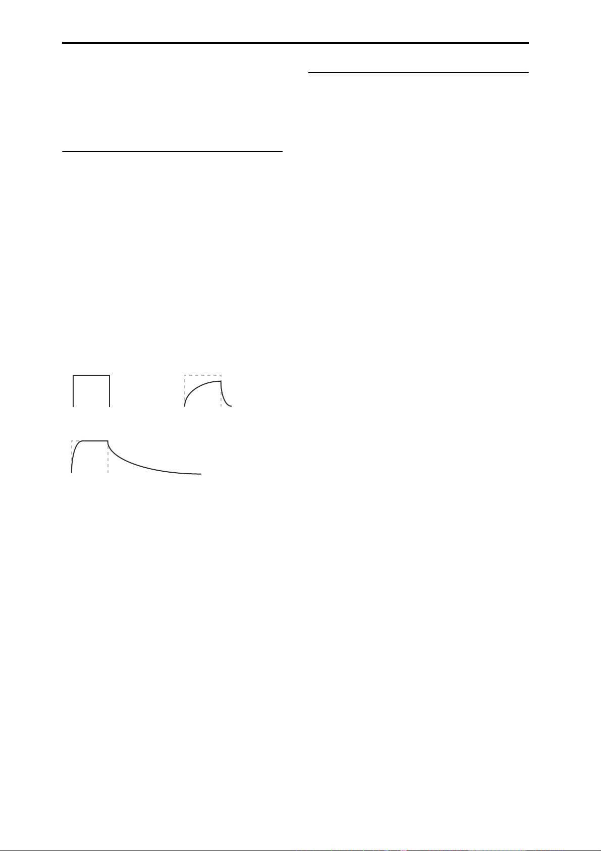
Program mode
AMS A Offset [–199...+199]
This controls the amount of offset for AMS A.
Setting Offset to +199 shifts an AMS input of –99 all the way
to +99. In conjunction with high AMS A Amount values,
this can be useful for creating clipped shapes, such as shown
in the last of the “AMS Mixer Offset examples,” above.
Smoothing
This Mixer Type smooths out the AMS input, creating more
gentle transitions between values. You have separate control
of the amount of smoothing during the attack (when the
signal is increasing) and decay (when it’s decreasing).
The higher the Attack and Decay settings, the more the
input will be smoothed.
Low settings provide subtle controller smoothing, creating
more gradual aftertouch, for instance. Higher settings create
auto-fade effects, transforming a quick gesture into a longer
fade-in and/or fade-out event.
Smoothing can also be used to alter the shape of
programmable mod sources, such as LFOs and EGs. For
instance, you can turn a “blip” into a simple envelope shape,
as shown below.
AMS Mixer Smoothing examples
Original AMS A: Smoothing with Long Attack
and Short Release:
Shape
This Mixer Type adds curvature to the AMS input. This
applies deformation to the AMS input. You can use this to
customize a controller curve, such as the exponential curve
of the joystick or the logarithmic curve of velocity control. It
can also alter the shape of programmable modulation
sources, such as EGs and LFOs.
Note: Shape only affects AMS signals which already have
some amount of slope, such as EGs, triangle and sine LFOs,
and so on. It does not affect signals which only contain
abrupt transitions, such as square waves.
AMS A [List of AMS Sources]
This selects the AMS input source to be shaped.
For a list of AMS sources, please see “AMS (Alternate
Modulation Source) List” on page 374.
Shape [–99...+99]
This controls the amount of curvature, and whether the
curves are concave or convex. As you can see in the graphic
examples, the shape will tend to emphasize certain value
ranges, and de-emphasize others.
For example, let’s say that you are using a triangle LFO,
through Shape, to modulate filter cutoff. If Shape
emphasizes the high value range, the filter will spend more
time at the higher frequencies. If it emphasizes the low
range, the filter will spend more time at the lower
frequencies.
Smoothing with Short Attack & Long Release:
AMS A [List of AMS Sources]
This selects the AMS source to be smoothed.
For a list of AMS sources, please see “AMS (Alternate
Modulation Source) List” on page 374.
AMS A Attack [00...+99]
This controls the attack time of the smoother, or how long it
takes the smoother to reach a new, higher value.
Higher Attack settings mean longer times.
Depending on how quickly the AMS input value is
changing, high Attack settings may mean that the value is
never quite reached, as shown in “AMS Mixer Shape
examples,” above.
AMS A Decay [00...+99]
This controls the decay time of the smoother, or how long it
takes the smoother to reach a new, lower value.
Higher Decay settings mean longer times.
Mode [Symmetric, Asymmetric]
This selects whether the Shape parameter will produce one
or two curves. The graphic “AMS Mixer Shape examples”
may help to visualize how this works.
Asymmetric will produce a single curve, extending from
–99 to +99.
Symmetric will produce two matching curves extending
outwards from 0 to –99 and +99, respectively.
Bipolar and Unipolar AMS sources
To understand Shape, it helps to understand the difference
between bipolar and unipolar AMS sources.
Bipolar sources can swing all the way from –99 to +99, with
0 in the middle. Most LFOs are bipolar, for instance; so is
Pitch Bend.
Generally, bipolar AMS sources will work better with the
Asymmetric mode, but Symmetric may also produce
interesting results.
Unipolar sources only go from 0 to 99, with 50 in the
middle. MIDI controllers, such as JS+Y (CC#1), are all
unipolar. In practice, EGs are usually programmed to be
unipolar, even though the Filter and Pitch EGs do allow
both positive and negative levels.
With unipolar sources, it’s almost always better to use the
Symmetric mode. The Asymmetric mode can cause offsets
and other strange results.
54
Page 63

PROG P6: AMS/C.KTrk (AMS Mixer/Common Keyboard Track) 6–1: OSC1 AMS Mix1
AMS Mixer Shape examples
Bipolar Triangle Wave
Asymmetric
+99
0
–99
Symmetric
+99
0
–99
Bipolar Sawtooth Wave
+99
0
–99
Unipolar Triangle Wave
Asymmetric
(not recommended)
+99
0
–99
SymmetricAsymmetric
Symmetric
AMS A [List of AMS Sources]
This selects the AMS input source to be quantized.
For a list of AMS sources, please see “AMS (Alternate
Modulation Source) List” on page 374.
Number Of Steps [2...32]
This controls the severity of the effect. The lower the number
of steps, the more “steppy” the output will be.
For instance, when this is set to 2, there will be “steps” at 0,
50, and 99. With a bipolar AMS input, there will also be steps
at –50 and –99.
As another example, when it is set to 5, there will be steps at
0, 20, 40, 60, 80, and 99 (as well as –20, –40, –60, –80, and –99
for bipolar inputs).
Tip: Quantized Joystick Pitch Bend
You can use the joystick to create quantized pitch bends that
simulate sliding across the frets of a guitar, or jump-bend
sounds caused by differences in the length of the tube of a
trumpet. To do so:
1. Select the AMS Mixer as the Oscillator Pitch AMS
input.
2. Set the Pitch AMS Intensity to any exact half-step
value, such as +5.00, +7.00, etc.
3. Set the JS(+X), JS(–X) amount to 0.00.
4. In the AMS Mixer, select the JS X as AMS A.
5. Set the Number Of Steps to the same number you used
in Step 2.
Now, playing the joystick will create quantized pitch bends.
JSX will still produce smooth pitch bends, as usual, so you
can use both techniques together.
Shape = 0 (original waveform)
Shape = +99
Shape = –99
Quantize
This Mixer Type changes the input from a continuous signal
into a series of discrete steps. Instead of moving smoothly
between values, it will snap immediately from one value to
another.
You can use this to change the shape of LFOs or EGs, or to
force a controller to land on a few specific values.
AMS Mixer Quantize examples
Unipolar (e.g., JS+Y) Bipolar (e.g., LFO)
+99
Original
AMS A
Quantize
Steps = 8
Quantize
Steps = 16
0
–99
+99
0
–99
+99
0
–99
Gate Control
AMS Mixer, Type = Gate Control
Control
Fixed Value
AMS
Fixed Value
AMS
This Mixer Type lets you set up two different AMS sources
(or fixed AMS amounts), and then switch between the two
using a third AMS source.
It’s similar to an audio gate with a side-chain, but with even
more flexibility–since you get to choose what happens when
the gate is closed (below the threshold), as well as when it’s
open (above the threshold).
You can also choose whether the gate will be able to open
and close continuously in response to the control source, or
whether it only opens or closes at the beginning of the note,
and then stays that way over the note’s entire duration.
You can use the Gate to:
• Use a foot-switch (or other controller) to apply pitchbend or other effects to some notes, but not to others
• The parameter will be applied when the controller
reaches a specific threshold. For example, the velocity
value could control the filter resonance only if the
velocity value exceeds 90.
• Use the joystick, switches, or controllers to change
between two separate LFOs (or other AMS sources).
Below
At & Above
55
Page 64

Program mode
Gate Control:
Source [List of AMS Sources]
This selects the AMS source to control the gate.
Control At Note-On Only [Off, On]
When this is enabled (checked), the value of the Control
Source at note-on will select the output (Below Threshold
or At & Above Threshold). The selected output will then
remain active throughout the duration of the note,
regardless of any subsequent change in the Control Source’s
value.
Note that the output value itself can continue to change;
only the selection of Below or At & Above is fixed.
Threshold [–99...+99]
This sets the value of the Control Source at which the gate
opens or closes.
Gate Output:
If the value of the Control Source is less than the Threshold,
the Gate outputs the preset value or AMS source selected
under Below Threshold.
If the value of the Control Source is greater than or equal to
the Threshold, the Gate outputs the preset value or AMS
source selected in the At & Above Threshold parameter.
Below Threshold [Fixed Value, AMS A]
This selects whether Below Threshold uses a preset value,
or the selected AMS source.
Fixed Value [–99...+99]
This lets you set a specific value to be used when the
Control Source is less than the Threshold. This only applies
when Below Threshold is set to Fixed Value.
AMS A [List of AMS Sources]
This lets you set an AMS source to pass through the Gate
when the Control Source is less than the Threshold. This
only applies when Below Threshold is set to AMS A.
At & Above Thresh (At & Above Threshold)
[Fixed Value, AMS B]
This selects whether At & Above Threshold uses a preset
value, or the selected AMS source.
Fixed Value [–99...+99]
This lets you set a specific value to be used when the
Control Source is greater than or equal to the Threshold.
This only applies when At & Above Threshold is set to
Fixed Value.
AMS B [List of AMS Sources]
This lets you set an AMS source to pass through the Gate
when the Control Source is greater than or equal to the
Threshold. This only applies when At & Above Threshold
is set to AMS B.
6. On the OSC Pitch page, assign the AMS Mixer to control the pitch.
7. Turn off the foot switch, and while holding down a
chord, move the joystick in the X-direction. The pitch
will not change.
(If the pitch changes, go to the OSC Pitch page and set Pitch
“JS (+X) and “JS (–X)” to +00.)
8. Turn on the foot switch, and add a new note to the previous chord.
9. Move the joystick in the X-direction; pitch bend will be
applied only to the newly-played note.
The new note will bend, but the original chord (played
before you pressed on the foot-switch) will not.
Selective pitch-bend, using only the joystick
You can also use a single AMS source as both the Control
Source and a value source:
1. Set the Control Source to JS X.
2. Set Control At Note-On Only to On (checked).
3. Set the Threshold to 00.
4. Set Below Threshold to AMS A: JS X.
5. Set At & Above Threshold to a Fixed Value of 00.
6. On the OSC Pitch page, assign the AMS Mixer to control the pitch.
7. With the joystick in the center, play a chord, and hold it
through step 9.
8. Bend the joystick to the left, and then play a new note
above the chord.
(If the pitch changes, go to the OSC Pitch page and set Pitch
“JS (+X) and “JS (–X)” to +00.)
9. Use the joystick to bend the pitch of the new note.
The new note will bend, but the original chord (played
before you bent the joystick down) will not. This method is
particularly good for bending the top note of a chord up to
pitch.
Generating a static value
Sometimes, it can be handy to have a preset value as an
AMS source. The Gate is one way to create this. To do so:
1. Set both Below Threshold and At & Above Threshold
to Fixed Value, and enter the same value into each.
Now, the AMS mixer will always generate this static value.
▼6–1: Menu Command
• 0: Write Program ☞p.73
• 1: Exclusive Solo ☞p. 73
•2: Copy Oscillator ☞p. 74
•3: Swap Oscillator ☞p. 74
For more information, please see “Program: Menu
Command” on page 73.
Tips on using the Gate
Selective pitch-bend, using a switch
You can use Control At Note-On Only to apply an effect to
some notes, but not others, based on the state of an AMS
source at the start of the note. For instance:
1. Set the Control Source to Foot SW: CC#82
2. Set Control At Note-On Only to On (checked).
3. Set the Threshold to 50.
4. Set Below Threshold to a Fixed Value of +00.
5. Set At & Above Threshold to AMS B: JS X.
56
Page 65

PROG P6: AMS/C.KTrk (AMS Mixer/Common Keyboard Track) 6–2: OSC1 AMS Mix2
6–2: OSC1 AMS Mix2
This is the second AMS Mixer for Oscillator 1. The
parameters are exactly the same as those for AMS Mixer 1,
as described under “6–1a: AMS Mixer 1” on page 52.
6–4: OSC 2 AMS Mix1 , 6–5: OSC 2 AMS Mix2
This page controls the two AMS Mixers for Oscillator 2.
These are available only when the Oscillator Mode is set to
Double; if not, the page will be grayed out.
The parameters are identical to those for Oscillator 1, as
described under “6–1: OSC1 AMS Mix1,” on page 52.
6–7: Common KeyTrk 1 (Common Keyboard Track 1)
6–7
Menu
6–7a
6–7b
The two Oscillators share two Common keyboard tracking
generators, in addition to each Oscillator’s dedicated
keyboard tracking for the Filter and Amp. You can use these
Common keytracks as AMS sources for modulating most
AMS destinations.
The Common Keyboard Track parameters are shared by the
entire Program, but the actual AMS values are calculated
individually for each voice.
What does Keyboard Tracking do?
At its most basic, keyboard tracking lets you vary the
modulation amount as you play up and down the keyboard.
This can be useful for making the timbre consistent across
the entire range, or adjusting parameters according to pitch.
The M50 keyboard tracking can be fairly complex, if desired.
You can create different rates of change over up to four
different parts of the keyboard. For instance, you can:
•Make the modulation increase very quickly over the
middle of the keyboard, and then increase more slowly–
or not at all–in the higher octaves.
•Make the modulation increase as you play lower on the
keyboard.
• Create abrupt changes at certain keys, for split-like
effects.
Common Keyboard Tracking
At the Center Key, the AMS value is always 0.
AMS
+99
Ramp:
+99
0
–99
Ramp = –50
Ramp = +99
Ramp:
+99
+50
00
–50
–99
–99
AMS
Low Break Center High Break
How it works: Keys and Ramps
The keyboard tracking works by creating four ramps, or
slopes, between five keys on the keyboard. The bottom and
top keys are fixed at the bottom and top of the MIDI range,
respectively. You can set the other three keys–named Low
Break, Center, and High Break–to be anywhere in between.
The four Ramp values control the rate of change between
each pair of keys. For instance, if the Low-Center Ramp is
57
Page 66
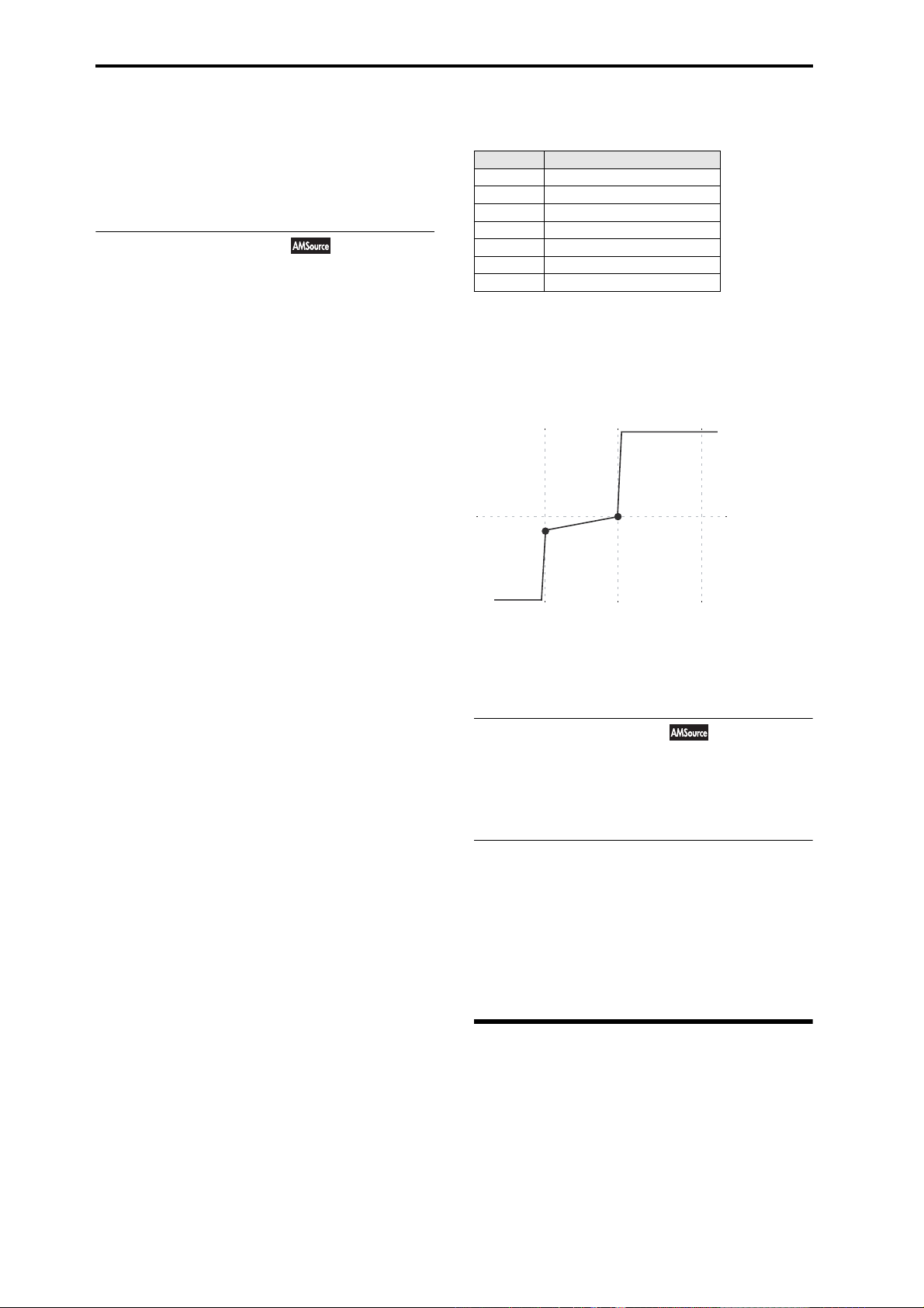
Program mode
set to 0, the value will stay the same between the Low Break
key and the Center key.
The Key value will be the break point, and Ramp specifies
the slope of the lower region and higher region on the
keyboard.
If Key is Center, keyboard tracking will have no effect.
6–7a: Keyboard Track 1
Key
Low Break [C–1...G9]
This specifies the note that will be the break point
connecting the two sloped lines in the low region.
Center [C–1...G9]
This specifies the note that will be the break point in the
center of keyboard tracking. At this key, the keyboard
tracking has no effect on the AMS destinations.
High Break [C–1...G9]
This specifies the note that will be the break point
connecting the two sloped lines in the high region.
Entering notes from the keyboard
You can enter note numbers directly by playing them on the
keyboard. To do so:
1. Select one of the Key parameters.
2. Hold down the ENTER switch.
3. While holding ENTER, play a note on the keyboard.
Ramp
Positive ramp values mean that the keyboard tracking
output increases as you play farther from the Center Key;
negative ramp values mean that it decreases.
Because of this, the meanings of positive and negative Ramp
settings will change depending on whether the ramp is to
the left or right of the Center Key.
Bottom-Low and Low-Center: negative ramps make the
keyboard tracking’s output go down as you play lower on
the keyboard, and positive ramps make the output go
higher.
Center-High and High-Top: negative ramps make the
keyboard tracking’s output go down as you play higher on
the keyboard, and positive ramps make the output go up.
Bottom-Low [–Inf, –99...+99, +Inf ]
This sets the slope between the bottom of the MIDI note
range and the Low Break key. For normal key track, use
negative values.
Low-Center [–Inf, –99...+99, +Inf]
This sets the slope between the Low Break and Center keys.
For normal key track, use negative values.
The table below shows how the Ramps affect the AMS
output:
Ramp value AMS change
–Inf goes to –99 in 1 half-step
–99 –20 per octave
–50 –10 per octave
0 no change
+50 +10 per octave
+99 +20 per octave
+Inf goes to +99 in 1 half-step
+Inf and –Inf ramps
+Inf and –Inf are special settings which create abrupt
changes for split-like effects. When a ramp is set to +Inf or
–Inf, the keyboard tracking will go to its extreme highest or
lowest value over the span of a single key.
+Inf and –Inf Ramps
Ramp = +Inf
Ramp = –50
Ramp = –Inf
Key Low Center Key High
Note: If you set the Center-High ramp to +Inf or –Inf, the
High-Top parameter will be grayed out. Similarly, if you set
the Low-Center ramp to +Inf or –Inf, the Bottom-Low ramp
will be grayed out.
6–7b: Keyboard Track 2
This is the second Common keyboard tracking generator.
Its parameters are exactly the same as those for Keyboard
Track 1, as described under “6–7a: Keyboard Track 1” on
page 58.
▼6–7: Menu Command
• 0: Write Program ☞p.73
• 1: Exclusive Solo ☞p. 73
•2: Copy Oscillator ☞p. 74
•3: Swap Oscillator ☞p. 74
For more information, please see “Program: Menu
Command” on page 73.
Center-High [–Inf, –99...+99, +Inf]
This sets the slope between the Center and High Break
keys. For normal key track, use positive values.
High-Top [–Inf, –99...+99, +Inf]
This sets the slope between the High Break key and the top
of the MIDI note range. For normal key track, use positive
values.
58
6–8: Common KeyTrk 2
(Common Keyboard Track 2)
Here you can make settings for the second common
keyboard track.
For more information, please see “6–7: Common KeyTrk 1
(Common Keyboard Track 1)” on page 57.
Page 67
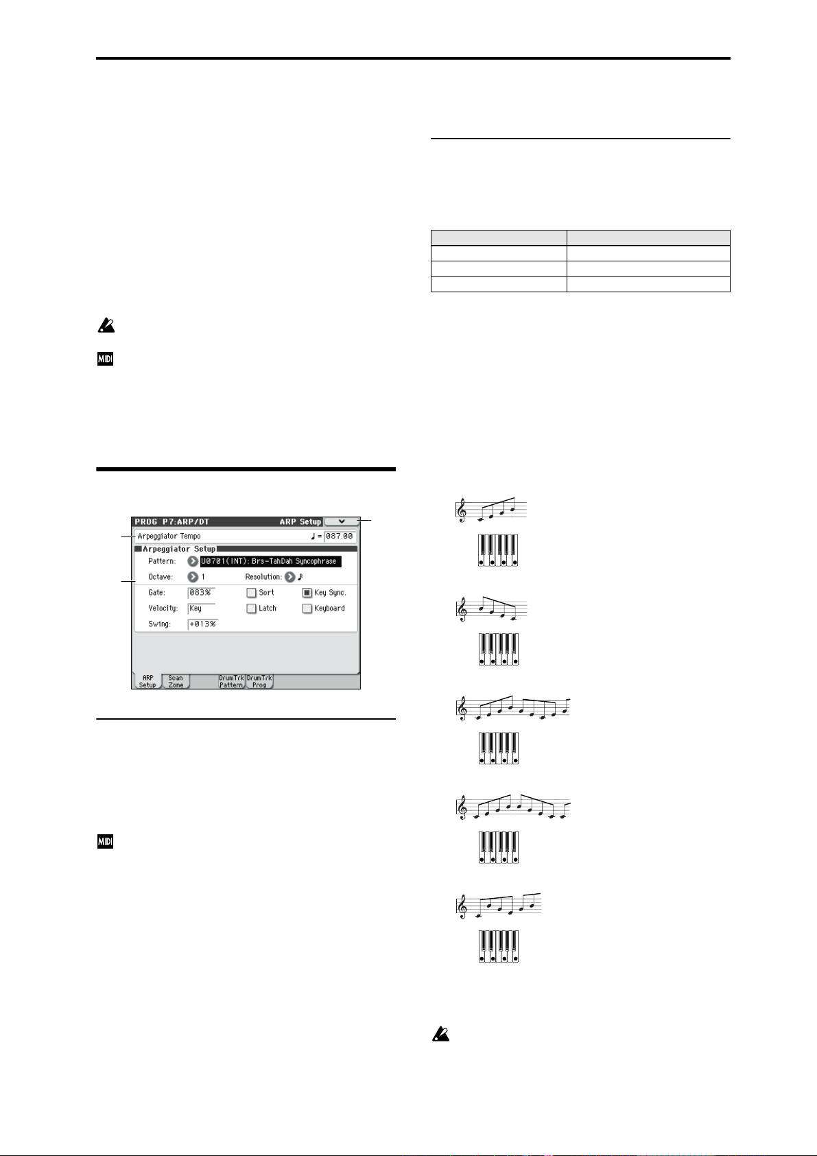
PROG P7: ARP/DT (Arpeggiator/Drum Track) 7–1: ARP Setup
UP
PROG P7: ARP/DT (Arpeggiator/Drum Track)
Here you can make settings for the arpeggiator used by the
program.
You can make settings so that when you select a program,
these arpeggiator settings will automatically switch to the
arpeggiator settings that are memorized in the selected
program. (Global P0: 0–1c Load ARP when changing
“Program” on page 217)
The arpeggiator can be switched on/off by the ARP ON/
OFF switch. When on, the key LED will light.
The settings of the ARP ON/OFF switch, TEMPO, Control
Surface ARP GATE, VELOCITY, LENGTH and OCTAVE
knobs can be saved for each program.
These settings will be valid when “Load ARP when
changing” Program (Global 0–1c) is checked.
You can control the arpeggiator from an external
sequencer, or record note data generated by the
arpeggiator onto an external sequencer. (See page 250)
Note: “Pattern,” “Resolution,” “Octave,” “Sort,” “Latch,”
“Key Sync.,” “Keyboard,” and “ (Tempo)” can also be set
from the P0: Play, Arpeggio page.
7–1: ARP Setup
7–1
7–1a
Menu
7–1b: Arpggiator Setup
Pattern* [P0...P4, U0000(INT)...U0899(INT),
U0900(USER)...U1027(USER)]
Selects the arpeggio pattern.
Preset/User No Contents
P0...P4
U0000(INT)...U0899(INT )
U0900(USER)...U1027(USER)
Note: U0000(INT)–U1027(USER) are rewritable. Use Global
P6: Arpeggio Pattern to create arpeggio patterns.
Note: Arpeggio patterns U0900(USER)–U1027(USER) can
be selected using the numeric keys 0–9 and the ENTER
switch.
Example: Preset pattern
The way in which the pattern is played will depend on
settings such as “Octave” and “Sort.” P0–P4 in the following
diagrams show how the arpeggio will be played when
“Octave” is set to 1, and “Sort” is checked. P4: RANDOM is
only one possibility.
P0: UP
Preset arpeggio patterns
Preloaded arpeggio patterns
User arpeggio patterns
7–1b
7–1a: Tempo
(Tempo)* [040.00...300.00, EXT]
Sets the tempo, expressed as beats per minute.
You can also adjust this by turning the front panel TEMPO
knob. Alternatively, you can set the tempo by pressing the
TAP TEMPO switch at the desired interval.
When MIDI Clock (Global P1: 1–1b) is set to either
External MIDI or External USB, this parameter will
indicate EXT, and the arpeggiator will synchronize to
the MIDI Clock received from an external MIDI device.
P1: DOWN
DOWN
P2: ALT1
ALT1
P3: ALT2
ALT2
P4: RANDOM
RANDOM
Octave* [1, 2, 3, 4]
Specifies the number of octaves in which the arpeggio will
be played.
If a user arpeggio pattern is selected, the range of the
arpeggio will depend on the Octave Motion (Global P6:
6–1b) setting.
59
Page 68

Program mode
Octave: 4
UP
Resolution* [ , , , , , ]
Specifies the timing resolution of the arpeggio. The notes of
the arpeggio will be played at the interval you specify: ,
, , , , or . The speed of the arpeggio pattern is
determined by the “Arpeggiator Tempo ” and the
“Resolution.”
Gate [000...100(%), Step]
Specifies the length (gate time) of each note in the arpeggio.
000–100(%): Each note will be played with the specified gate
time.
Step: This is available when a user arpeggio pattern
U0000(INT)–U1027(USER) is selected for Pattern. When
this is selected, the gate time specified for each step will be
used.
The gate time can also be controlled by the Control Surface
ARP GATE knob. Rotating the knob toward the left will
shorten the gate time, and rotating it toward the right will
lengthen the gate time. When the knob is at the 12 o’clock
position, the gate time will be as specified here.
Velocity [001...127, Key, Step]
Specifies the velocity of the notes in the arpeggio.
001–127: Each note will sound with the specified velocity
value.
Key: Each note will sound with the velocity value at which
it was actually played.
Step: This is available when an user arpeggio pattern
U0000(INT)–U1027(USER) is selected for “Pattern.” When
this is selected, the velocity specified for each step will be
used.
The velocity can also be controlled by the Control Surface
ARP VELOCITY knob. Rotating the knob toward the left
will decrease the velocity, and rotating it toward the right
will increase the velocity. When the knob is at the 12 o’clock
position, the velocity will be as specified here.
When a preload user arpeggio pattern is selected, setting the
Gate or Velocity to Step will add a sense of groove to the
arpeggio pattern.
Swing [–100...+100(%)]
This parameter shifts the timing of the odd-numbered notes
of the arpeggio.
When Resolution =
Step
123456789
Off (unchecked): Notes will be arpeggiated in the order in
which you pressed them.
Sort
OFF, UP
Sort
ON, UP
Latch* [Off, On]
Specifies whether or not the arpeggio will continue playing
after you take your hand off of the keyboard.
On (checked): The arpeggio will continue playing after you
remove your hand from the keyboard.
Off (unchecked): The arpeggio will stop when you remove
your hand from the keyboard.
Key Sync.* [Off, On]
Specifies whether the arpeggio pattern will begin when you
press a key, or whether it will always follow the “ (Tempo)”
(Prog 0–1a).
On (checked): The arpeggio pattern will start playing from
the beginning when a note-on occurs from a condition
where no keys are pressed. This setting is suitable when you
are playing in realtime and want the arpeggio to play from
the beginning of the measure.
Off (unchecked): The arpeggio pattern will always play
according to the “ (Tempo).”
Keyboard* [Off, On]
This specifies whether the notes you play on the keyboard
will be sounded as usual in addition to being sounded as
part of the arpeggio.
On (checked): The notes you play will be sounded on their
own, in addition to being sounded as part of the arpeggio.
For example if you simultaneously press two or more notes,
they will be sounded as usual in addition to being played as
arpeggiated notes.
Off (unchecked): Only the arpeggiated notes will be heard.
Note: *: These parameters can also be set from “P0: Play,
Arpeggiator.”
Note: You can use the menu command Copy Arpeggiator to
copy arpeggiator settings from another program or
combination (see page 75).
▼7–1: Menu Command
• 0: Write Program ☞p.73
• 1: Exclusive Solo ☞p. 73
•2: Copy Arpeggiator ☞p. 75
For more information, please see “Program: Menu
Command” on page 73.
–50 –25 +25 +50
Swing
Sort* [Off, On]
This specifies the order in which the notes you press will be
arpeggiated.
On (checked): Notes will be arpeggiated in the order of their
pitch, regardless of the order in which you pressed them.
60
Page 69

PROG P7: ARP/DT (Arpeggiator/Drum Track) 7–2: ARP Scan Zone
7–2: ARP Scan Zone
7–2
7–2a
7–2b
7–2c
7–2a: Arpeggiator Tempo
(Tempo) [040.00...300.00, EXT]
For more information, please see “ (Tempo)*” on page 59.
7–2b: Zone Map
This shows the Scan Zone.
Key zone of arpeggiator
Velocity zone of
arpeggiator
Menu
▼7–2: Menu Command
• 0: Write Program ☞p.73
• 1: Exclusive Solo ☞p. 73
For more information, please see “Program: Menu
Command” on page 73.
C–1 G9
7–2c: Scan Zone
This shows the Scan Zone setting.
Top Key [C–1…G9]
Bottom Key [C–1…G9]
These parameters specify the range of notes (keys) for which
the arpeggiator will function. Top Key is the upper limit,
and Bottom Key is the lower limit.
The arpeggiator will operate when you play keys within the
specified range. Keys outside of this range can be played in
the normal manner, and will not be affected by the
arpeggiator on/off.
For example if you set Pattern to P0: UP, check Latch, set
Top Key to B3, and Bottom Key to C-1, playing a note B3 or
lower will trigger the arpeggiator. Since Latch is on, the
arpeggio will continue even after you release the keys. You
can use the C4 and higher keys to play conventionally along
with the arpeggio sounded by the B3 and lower keys. To
change the arpeggio, play keys in the range of B3 and below.
Top Velocity [001…127]
Bottom Velocity [001…127]
Specifies the range of velocities for which the arpeggiator
will function. Top Velocity is the upper limit, and Bottom
Velocity is the lower limit.
The arpeggiator will operate when you play notes with a
velocity (playing strength) that is within the specified range.
Notes played with a velocity outside this range will be
sounded normally, without regard to the arpeggiator on/off.
Note: Note number and velocity can also be entered by
holding down the ENTER switch and playing a note on the
keyboard.
61
Page 70
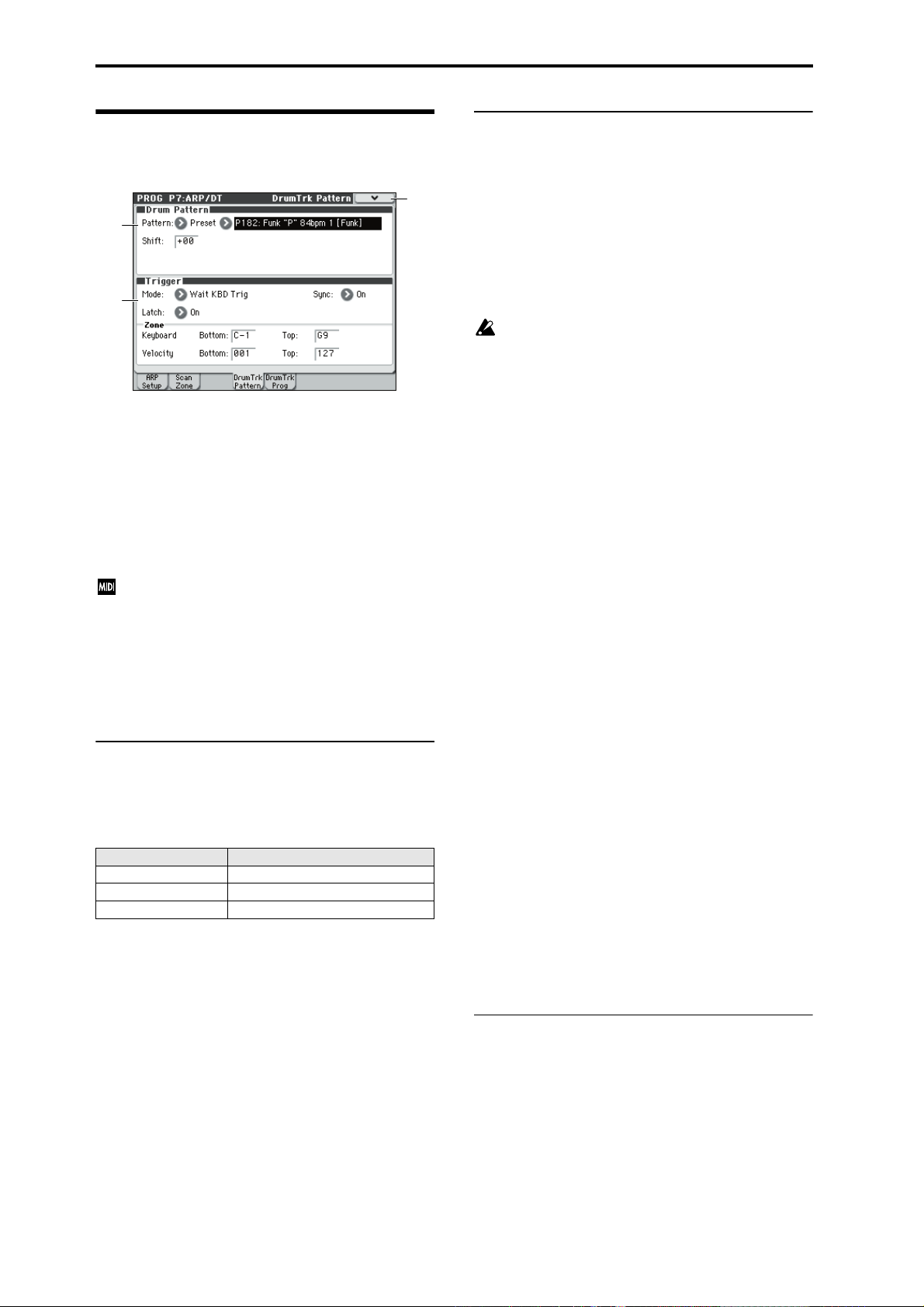
Program mode
7–4: DrumTrk Pattern (DrumTrack Pattern)
7–4
7–4a
7–4b
Here you can select a drum track pattern and specify how it
will sound.
The drum track lets you easily produce a rhythm section
using the M50’s high-quality drum programs and a rich
variety of drum track patterns.
You can edit the program or try out different phrases while
listening to the drum track.
When you come up with a phrase you like, you can use the
Auto Song Setup function to easily record it into the
sequencer.
In Program mode, the drum track patterns are triggered
on the Global MIDI channel. The MIDI transmit
channel is specified by the DrumTrack Prog MIDI Ch
(Global P1: MIDI– MIDI Basic). Use the DrumTrack
Prog MIDI Out (Global P1: MIDI– MIDI Basic) setting
to specify whether the pattern will transmit MIDI note
data. The default setting is channel 10.
The drum track program will not transmit or receive
MIDI program changes.
Menu
7–4b: Trigger
Trigger Mode [Start Immediately, Wait KBD Trig]
Start Immediately: When you press the DRUM TRACK
ON/OFF switch to turn it on (LED lit), the drum track
pattern will start according to the Sync setting. When you
turn it on, the drum track pattern will stop.
Wait KBD Trig: When you press the DRUM TRACK ON/
OFF switch to turn it on (LED lit), the drum pattern will wait
to start. When you play the keyboard, or when a MIDI noteon is received, the drum pattern will start according to the
Sync setting.
If you’ve selected Start Immediately, the DRUM
TRACK ON/OFF switch will always be saved in the
OFF state.
Sync [Off, On]
Off: The drum pattern will not synchronize to the currentlyrunning arpeggiator, but will start immediately.
On: The drum pattern will synchronize to the currentlyrunning arpeggiator.
Note: Use P7–1: Arpeggiator Setup Key Sync to specify
whether the arpeggiator will synchronize to the currentlyrunning drum pattern.
Latch [Off, On]
This is valid if Trigger Mode is Wait KBD Trig.
Off: If the DRUM TRACK ON/OFF switch is on (LED
blinking), the pattern will start when you play the keyboard
(note-on). The pattern will stop when you release the
keyboard (note-off).
On: If the DRUM TRACK ON/OFF switch is on (LED
blinking), the pattern will start when you play the keyboard
(note-on). The pattern will continue when you release the
keyboard (note-off). The pattern will stop when you turn the
DRUM TRACK ON/OFF switch off (LED dark).
7–4a: Drum Pattern
Pattern [Preset, User]
[(Preset): P000...671, (User): U000...U999]
This selects the drum pattern.
Preset/User No. Contents
P000 Off
P000...671 Preset drum patterns
U000...U999 For user/preloaded drum patterns
•U000–U999 can be written. Patterns you create in
Sequencer mode can be converted into user drum
patterns. (See page 208)
Shift [–24...+00...+24]
This transposes the drum pattern in semitone steps. This
means that the instruments of the drum kit will change.
Zone:
Keyboard
Bottom [C–1...G9]
To p [C–1...G9]
This is valid if Trigger Mode is set to Wait KBD Trig.
It specifies the range of keys that will start the drum pattern.
Velocity
Bottom [001...127]
To p [001...127]
This is valid if Trigger Mode is set to Wait KBD Trig.
It specifies the range of velocities that will start the drum
pattern.
▼7–4: Menu Command
• 0: Write Program ☞p.73
• 1: Exclusive Solo ☞p. 73
• 2: Copy Drum Track ☞p. 74
• 3: Erase Drum Track Pattern ☞p. 75
For more information, please see “Program: Menu
Command” on page 73.
62
Page 71

PROG P7: ARP/DT (Arpeggiator/Drum Track) 7–5: DrumTrk Program (DrumTrack Program)
7–5: DrumTrk Program (DrumTrack Program)
7–5
Menu
7–5a
7–5b
7–5a: Drum Track Programs
Program Select [Drum Category Programs]
Here you can select the drum program that will be used by
the drum track.
Note: Only programs of the Drum category can be selected.
If data is loaded or a system exclusive message is
received so that the selected program is no longer a
Drum category program, it will be replaced with the
first program of the Drum category.
The drum track program will not transmit or receive
MIDI program changes.
Volume [000...127]
This adjusts the volume of the drum track program.
Play/Mute [Mute, Play]
This mutes the drum track program. The setting will
alternate each time you press the Play/Mute button.
Mute: The drum track program will not be heard (Mute).
Play: The drum track program will be heard (Play).
Using the OSC/DrumTrk Mixer to make Drum
Track settings
You can use the P0–4: OSC/DrumTrk Mixer page to edit the
Play/Mute, Solo On/Off, and Volume settings of the drum
track. (See “0–4b: OSC/DrumTrack Mixer” on page 4.)
Detune [–1200...+1200]
This adjusts the pitch in one-cent steps. One cent is 1/100th
of a semitone.
The pitch of each drum kit is specified in Global P5: Drum
Kit.
You can control this using RPNs.
7–5b: EQ
Auto Load Program EQ [Off, On]
On (checked): When you switch the drum track program,
the 3-band EQ values specified for the program will
automatically be loaded. Normally you will leave this
checked.
You are free to edit the 3-band EQ values that are
automatically loaded. You will be making changes based on
the settings of the original program.
Off (unchecked): The 3-band EQ values specified for the
program will not be loaded when you switch the drum track
program.
7–5c
•When you select a drum track: Check this to load the 3band EQ setting of the program. You can adjust the
drum track program’s EQ based on these settings.
•When you’ve edited the drum track program’s EQ
settings and want to leave them fixed: Uncheck this
item. The EQ settings will not change when you select
programs.
Bypass [On, Off]
When Bypass is checked, all of the EQ will be disabled,
including the Input Trim.
Bypass can be convenient for comparing the results of the
EQ with the original signal.
Input Trim [00...99]
This controls the volume level going into the EQ. This
setting corresponds to the volume; a value of 50 corresponds
to –6 dB, and a setting of 25 corresponds to –12 dB.
High settings of the Low, Mid, and High Gain controls can
cause substantial increases in the overall level. You can
compensate for this by turning down the input trim.
High Gain [–18.0...+00.0...+18.0dB]
This controls the gain of the 10 kHz High Shelf EQ, in
increments of 0.5 dB.
Mid Frequency [100Hz...10kHz]
This sets the center frequency for the Mid sweep EQ.
Mid Gain [–18.0...+00.0...+18.0dB]
This controls the gain of the Mid Sweep EQ, in increments of
0.5 dB.
Low Gain [–18.0...+00.0...+18.0dB]
This controls the gain of the 80 Hz Low Shelf EQ, in
increments of 0.5 dB.
7–5c: Bus
Bus Select [Dkit, L/R, IFX1...5, Off]
This specifies the bus that will output the drum track
program.
Dkit: The Bus (IFX/Output) Select, FX Control Bus, Send1
(to MFX1), and Send2 (to MFX2) settings (Global 5–4b) for
each key of the drum kit used by the selected drum track
program will be valid. Choose this setting if you want to
apply separate insert effects to each drum instrument.
When making Dkit settings, you will normally use IFX.
Patch to specify the output destination.
L/R: Output to the L/R bus.
IFX1, 2, 3, 4, 5: Output to the IFX1–5 bus.
Off: The sound will not be output to the L/R bus, or IFX1–5
bus. Use the Off setting if you have connected the drum
track program output in series to a master effect. Use Send1
(to MFX1) or Send2 (to MFX2) to adjust the send level.
FX Control Bus [Off, 1, 2]
This sends the output of the drum track program to the FX
Control bus (two mono channels FX Ctrl1, 2).
The FX Control bus is used when you want to use another
audio signal to control the input of an effect. You can use the
two FX Control buses (two mono channels) to freely control
the effects in a variety of ways. For more information, please
see “FX Control Buses” on page 274.
63
Page 72

Program mode
Send 1 [000...127]
Send 2 [000...127]
These specify the send level at which the output of the drum
track program will be sent to each master effect.
Send 1: Send the signal to master effect 1.
Send 2: Send the signal to master effect 2.
If Bus (IFX/Output) Select is set to IFX1–5, the send levels to
the master effects are set by the post-IFX1–5 Send1 and
Send2 (Prog 8–2a).
You can use CC#93 to control Send 1, and CC#91 to
control Send 2.
IFX. Patch:
IFX1 [L/R, IFX1...5, Off]
IFX2 [L/R, IFX1...5, Off]
IFX3 [L/R, IFX1...5, Off]
IFX4 [L/R, IFX1...5, Off]
IFX5 [L/R, IFX1...5, Off]
Here, you can patch the Bus (IFX/Output) Select setting
specified for each key of the drum kit, temporarily changing
its connection destination from the originally specified
insert effect to some other destination. This can be executed
only if the drum track program’s Bus (IFX/Output) Select is
set to DKit and the Bus (IFX/Output) Select (Global 5–4b)
for each key of the drum kit is set to IFX1–5.
As the patch destination, choose an insert effect or L/R,
IFX1–5, or Off as the output bus.
Note: If you want to return the drum kit to its previous state,
change these settings to IFX1→IFX1, IFX2→IFX2,
IFX3→IFX3, IFX4→IFX4, and IFX5→IFX5.
For the preloaded kits, snare sounds are normally sent to
IFX1, kick sounds to IFX2, and other sounds to IFX3. In such
cases if you set Bus (IFX/Output) Select to Dkit, these
sounds will be sent to IFX1, IFX2, and IFX3, but IFX1 and
IFX2 are set for normal (non-drum) programs. In such cases,
you can use IFX.Patch to route these drum sounds to
unused IFX; for example, you might send the snare sounds
to IFX3, kick sounds to IFX4, and other sounds to IFX5. For
more information, please see “Effect Guide” on page 271.
▼7–5: Menu Command
• 0: Write Program ☞p.73
• 1: Exclusive Solo ☞p. 73
• 2: Copy Drum Track ☞p. 74
• 3: Erase Drum Track Pattern ☞p. 75
For more information, please see “Program: Menu
Command” on page 73.
64
Page 73

PROG P8: IFX (Insert Effect)
PROG P8: IFX (Insert Effect) 8–1: Routing
Here, you can make settings for the insert effects. For
instance, you can:
• Send the output of a oscillator to an insert effect
• Route a sound to an insert effect
•Make detailed settings for insert effects
•Make common LFO settings for effects
For more information, please see “Effect Guide” on
page 271.
8–1: Routing
8–1a
8–1b
8–1d
8–1
Menu
8–1c
8–1c: Use Dkit Setting
Use DKit Setting [Off, On]
This is shown if Oscillator Mode (Prog 1–1a) is set to
Drums. If Oscillator Mode is set to Single or Double, this
setting is ignored.
On (checked): The Bus (IFX/Output) Select, FX Control
Bus, Send 1, and Send 2 settings (Global 5–4b) for each key
of the selected drum kit will be used. Check this if you want
to apply an individual insert effect to each drum instrument.
Tip: In most preloaded drumkits, the drum instruments have
the same Bus (IFX/Output) Select settings according to their
type, as follows.
Snares → IFX1
Kicks → IFX2
Other → IFX3
Off (unchecked): The Bus (IFX/Output) Select (Prog 8–1b),
FX Control Bus (Prog 8–1b), OSC MFX Send (Prog 8–1d)
settings will be used. All drum instruments will be sent to
the specified bus.
8–1d: OSC MFX Send
OSC1:
8–1a: Routing Map
This graphic shows an overview of the insert effects,
including the routing of the oscillators to the effects, the
effects names and on/off status, chaining between the
effects, and the output bus to which the insert effects are
themselves routed.
This page lets you adjust the routing of the oscillators to the
insert effects. To adjust the other settings shown in this
graphic, please see “8–2: Insert FX Setup,” as described on
page 66.
8–1b: Bus Select (All OSCs to)
Bus (IFX/Output) Select [L/R, IFX1...5, Off]
This specifies the output bus for oscillators 1 and 2.
L/R: The oscillators will be output to the L/R bus. Normally
you will choose L/R.
IFX1…5: Output to the IFX1–5 busses.
Off: The oscillator will not be output from the L/R bus, or
IFX1–5 busses. Choose the Off setting if you want the
program oscillator output of the timbre to be connected in
series to a master effect. Use Send1 (to MFX1) and Send2 (to
MFX2) to specify the send levels.
FX Control Bus [Off, 1, 2]
Sends the output of the oscillator 1, 2 to an FX Control bus
(two-channel mono FX Ctrl 1 or 2).
Use the FX Control busses when you want a separate sound
to control the audio input of an effect. You can use two FX
Control busses (each is a two-channel mono bus) to control
effects in various ways.
For more information, please see “FX Control Buses” on
page 274.
OSC1 Send1 (to MFX1) [000...127]
Sets the volume (send level) at which the output of oscillator
1 will be sent to master effect 1. This applies only when Bus
(IFX/Output) Select (Prog 8–1b) is set to L/R or Off.
If Bus (IFX/Output) Select is set to IFX1–IFX5, the send
levels to master effects 1 and 2 are set by Send 1 and Send 2
(Prog 8–2a) after passing through IFX1–5.
OSC1 Send2 (to MFX2) [000...127]
Sets the volume (send level) at which the output of oscillator
1 will be sent to master effect 2. For more information, please
see “OSC1 Send1 (to MFX1)” on page 65.
OSC2:
OSC2 Send1 (to MFX1) [000...127]
OSC2 Send2 (to MFX2) [000...127]
Sets the volume (send level) at which the output of OSC2
will be sent to master effects 1 and 2. These parameters will
be valid when Oscillator Mode is set to Double and Bus
(IFX/Output) Select is set to L/R or Off.
CC#93 controls OSC 1/2’s Send 1 level, and CC#91
controls the Send 2 level. These are controlled on the
global MIDI Channel (Global 1–1a). The actual send
level is determined by multiplying these values with
the send levels of each oscillator.
▼8–1: Menu Command
• 0: Write Program ☞p.73
• 1: Exclusive Solo ☞p. 73
•2: Copy Insert Effect ☞p.76
•3: Swap Insert Effect ☞p.76
For more information, please see “Program: Menu
Command” on page 73.
65
Page 74
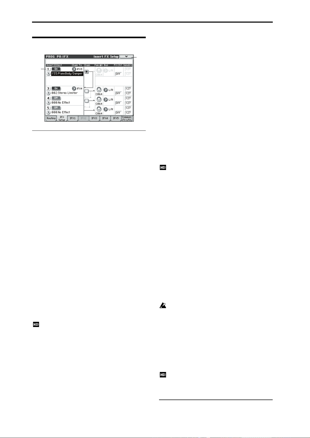
Program mode
8–2: Insert FX Setup
8–2
Menu
8–2a
8–2a: Insert Effect
Here, you can choose the type of each insert effect 1 through
5, its on/off status, chaining, and adjust the post-IFX mixer
settings. For insert effects, the direct sound (Dry) is always
stereo-in and out. The input/output configuration of the
effect sound (Wet) depends on the effect type. For more
information, please see “Insert Effects (IFX1–IFX5)” on
page 276.
You can chain two or more effects into the same downstream effect. For instance, both IFX1 and IFX2 can be
chained to IFX5.
Effects can also join a chain in the middle. For instance, you
can chain IFX3 to IFX4 to IFX5, and then chain IFX2 to IFX5
as well.
The Pan:#8, Bus (Bus Select), Ctrl (FX Control Bus), and
Send1/2 settings apply only to the last effect in the chain.
However, any effect in the chain can be sent to the FX
Control buses.
IFX1: Chain [Off, On]
IFX2: Chain [Off, On]
IFX3: Chain [Off, On]
IFX4: Chain [Off, On]
This enables the chain, as set up by the Chain to parameter,
above.
Pan:#8:
Pan: #8 (Post IFX PanCC#8) [L000...C064...R127]
Specifies the panning immediately after the insert effect.
You can use CC#8 to control this.
Bus:
Insert Effect:
IFX1...4 [000...170]
IFX5 [000...153]
This selects the effect type for insert effect.
IFX5 cannot use double-size effects (154–170). If you use a
double-size effect, the next insert effect will be unavailable.
For example if you select a double-size effect for IFX1, you
won’t be able to use IFX2.
Category/IFX Select menu
When you press the popup button, the Category/IFX Select
menu will appear, letting you select effects by category. Use
the tabs to select a category, and then select an effect within
that category. Press the OK button to execute your selection,
or press the Cancel button to cancel.
IFX1...5: IFX On/Off [Off, On]
Switches the insert effect on/off.
If this is off, the input will simply be passed to the output.
(When 000:No Effect is selected, there’s no difference
between On and Off.)
The setting will alternate between on and off each time you
press the button.
Separately from this setting, you can use MIDI CC #92
(on the global MIDI Channel (Global 1–1a)) to turn all
insert effects off. A value of 0 turns them off, and values
of 1–127 restore the original setting.
Chain:
IFX1: Chain to [IFX2...IFX5]
IFX2: Chain to [IFX3...IFX5]
IFX3: Chain to [IFX4...IFX5]
You can chain up to five insert effects together in series, to
create more complex effects. Set up the chain using this
parameter, and then enable it using the Chain check box,
below.
Effects must be chained in ascending numeric order. For
example, IFX1 can be chained to any of IFX2 through IFX5,
and IFX2 can be chained to IFX3 through IFX5.
66
Bus (Bus Select) [Off, L/R]
Specifies the bus to which the signal will be sent
immediately after the insert effect.
L/R: The signal will be sent to the L/R bus, which passes
through TFX and then goes to the AUDIO OUTPUT L/R
outputs. This is the default setting.
Off: The signal will not be sent directly to the L/R outputs.
This setting is useful if you want to:
Use Send 1 or 2 to route the signal entirely through the
master effects, without sending the dry signal to the
outputs.
Use the FX Control Bus to route the signal to an effects sidechain, such as a gate or vocoder, without being heard
directly at the outputs.
Ctrl:
Ctrl (FX Control Bus) [Off, 1, 2]
Sends the post-IFX signal to the FX Control busses. For more
information, please see “FX Control Bus” on page 65.
If you’re using Ctrl (FX Control Bus) as an input signal
for Vocoder etc., a feedback loop will occur if you
output to the same bus as specified here, and oscillation
will occur. Set this with care to avoid creating a loop.
Send1/2:
Send1 [000...127]
Send2 [000...127]
These adjust the level at which the post-IFX signal is sent to
master effects 1 and 2. This is valid if Bus (Bus Select) is set
to L/R or Off.
You can use CC#93 to control the Send 1 level, and
CC#91 to control the Send 2 level. The global MIDI
channel specified by MIDI Channel (Global 1–1a) is
used for these messages.
▼8–2: Menu Command
• 0: Write Program ☞p.73
Page 75
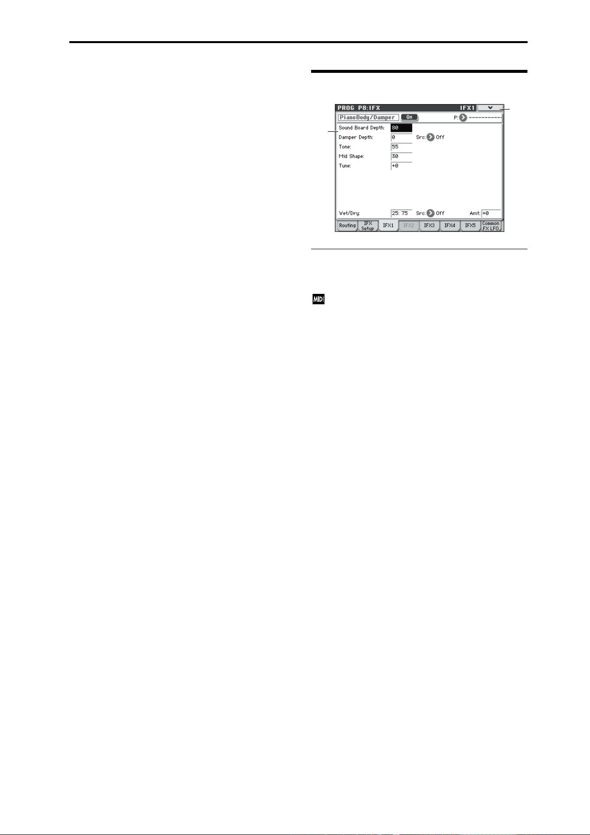
• 1: Exclusive Solo ☞p. 73
•2: Copy Insert Effect ☞p.76
•3: Swap Insert Effect ☞p.76
For more information, please see “Program: Menu
Command” on page 73.
PROG P8: IFX (Insert Effect) 8–3: IFX1
8–3: IFX1
8–3a
8–3a: Insert Effect 1 (IFX1)
Here you can edit the parameters of the insert effect you
selected in the P8: IFX– Insert FX Setup page.
Effect dynamic modulation (Dmod) is controlled on the
global MIDI Channel (Global 1–1a). For more
information, please see “Dynamic Modulation Source
List” on page 380.
8–3
Menu
IFX1 On/Off [Off, On]
This turns the insert effect on and off. It is linked with the
on/off setting in the Insert FX Setup page.
P (Effect Preset)
[P00, P01...15, U00...15, ---------------]
Effect Presets let you easily store and recall all of the settings
for an individual effect. You can store up to 16 user presets
for each effect type, in addition to 15 re-writable factory
presets.
The same presets appear in all of the modes (Program,
Combination, and Sequencer).
Note that edits to effects parameters are automatically
stored with the Program–you don’t need to store them as an
Effect Preset. Presets just make it easier to re-use your
favorite settings.
For instance, you can save an Effect Preset while working on
a particular Program, and then later use the same Effect
Preset in a different Program, Combination, or Song.
P00: Initial Set: These are the default settings that are
recalled when you select an effect type in the Insert FX Setup
page. You can’t save your own settings here.
P01…P15: These contain preset data that Korg plans to
provide in the future. We recommend that you store your
settings in U00–U15.
U00…U15: These are areas in which you can store your own
settings.
---------------: This shows that no Effect Preset has been
selected. You’ll see this if you’ve just selected an effect,
written a Program, or selected a new Program. Selecting this
setting from the menu will not have any effect.
Note: Programs save the effects parameter settings, but they
don’t save the number of the selected Effect Preset. If you
select an Effect Preset, and then save the Program, the Effect
Preset setting will revert to “--------------.”
Using Effect Presets
1. Select an effect in the Insert FX Setup page.
2. The P00: Initial Set settings will be recalled.
“P (Effect Preset)” will indicate --------.
67
Page 76

Program mode
3. Use “P (Effect Preset)” to select an effect preset: P00–
P15 or U00–U15.
The stored parameters will be recalled. Note that this will
overwrite all parameters of the effect.
4. Edit the recalled parameters as desired.
5. If you’ve come up with settings you like and want to
save them as a new preset, use the Write FX Preset
menu command.
8–8: Common FX LFO
8–8a
8–8
Menu
IFX1 Parameters:
IFX1 Parameters
This tab shows the parameters for IFX1, as selected on the
Insert FX Setup page.
For details on the specific parameters of each effect, please
see “Insert Effects (IFX1–IFX5)” on page 276.
▼8–3: Menu Command
• 0: Write Program ☞p.73
• 1: Exclusive Solo ☞p. 73
•2: Copy Insert Effect ☞p.76
•3: Swap Insert Effect ☞p.76
• 4: Write FX Preset ☞p.77
For more information, please see “Program: Menu
Command” on page 73.
8–4: IFX2, 8–5: IFX3, 8–6: IFX4, 8–7: IFX5
Here you can edit the effect parameters for the insert effects
selected in the Insert FX Setup page.
The parameters for IFX2–IFX5 are the same as for IFX1.
8–8b
The two Common FX LFOs allow you to synchronize LFObased modulation for multiple effects, such as phasers,
flangers, filters, and so on.
The Common LFOs control only the frequency, MIDI
synchronization, and reset options; each individual effect
still has its own settings for the LFO waveform and phase.
Within the individual effects, you can choose whether to use
one of the Common LFOs, or to use the individual effect’s
frequency, sync, and/or reset settings instead. This is done
via the effect’s LFO Type parameter; select Individual to use
the effect’s settings, or Common 1 or 2 to use the Common
LFOs.
Common FX LFO
Frequency[Hz]
Reset
Common FX LFO1
Generate original LFO waveform
LFO Type = Common1
Stereo Flanger
Stereo Phaser
Stereo Auto Pan
Wavefore m = Triangle
Phase Offset = 0 [deg]
Waveforem = Sine
Phase Offset = 0 [deg]
Waveforem = Sine
Phase Offset = +90 [deg]
Dmod (Dynamic Modulation) is controlled on the
global MIDI channel specified in Global mode P1.
68
8–8a: Common FX LFO1
Sync (Reset) [Off, On]
This specifies whether the Common FX LFO will be reset.
If this is on, operating the Source (below) will reset the
phase of the LFO.
Source (Dmod Source) [List of Dmod Sources]
If Sync (Reset) is on, this selects the Dmod source that will
reset the Common LFO. For a complete list of Dmod
sources, please see “Dynamic Modulation Source List” on
page 380.
This will be off when the modulation source specified
by Source has a value below 64, and on when the value
is above 64. The LFO will be reset when this value rises
from a level below 64 to a level higher than 64.
Frequency [0.02...20.00 (Hz)]
This specifies the frequency of the Common FX LFO. Higher
values make the LFO faster.
MIDI/Tempo Sync [Off, On]
Off (unchecked): The speed of the Common FX LFO will be
determined by the Frequency setting.
Page 77

On (checked): The speed of the Common FX LFO will be
determined by the BPM, Base Note, and Times settings (see
below).
BPM [MIDI, 40.00...300.00]
Base Note [ , 3 , , 3 , , 3 , , 3 , , ]
Times [01...32]
The frequency of the Common FX LFO will be the length of
the Base Note note value multiplied by the Times value,
relative to the tempo specified by the BPM value. If BPM is
set to MIDI, this will operate according to the (Tempo)
(Prog 0–1a) setting. If MIDI Clock (Global 1–1a) is set to
External, this will follow the MIDI clock of the master
device.
8–8b: Common FX LFO2
The parameters are identical to those for Common FX LFO1,
as described under “8–8a: Common FX LFO1,” above.
▼8–8: Menu Command
• 0: Write Program ☞p.73
• 1: Exclusive Solo ☞p. 73
•2: Copy Insert Effect ☞p.76
•3: Swap Insert Effect ☞p.76
• 4: Write FX Preset ☞p.77
For more information, please see “Program: Menu
Command” on page 73.
PROG P8: IFX (Insert Effect) 8–8: Common FX LFO
69
Page 78

Program mode
PROG P9: MFX/TFX (Master/Total Effect)
Here, you can make settings for the master effects and total
effect. For instance, you can:
• Route a sound to an master effects and total effect
•Make detailed settings for master effects and total effect
For more information, please see “Effect Guide” on
page 271.
9–1: Routing
9–1
Menu
9–1a
9–1b
Here you can specify the type of master effects and total
effect, and turn them on/off.
The master effects are sent to the L/R bus. The total effect is
inserted into the L/R bus.
9–1a: MFX1, 2
The master effect does not output the direct sound (Dry).
Adjust the Return 1 and Return 2 return levels to return the
signal to the L/R bus and mix it with the L/R bus signal.
The master effects are stereo-in/out, but depending on the
selected effect type, the output may be monaural. For more
information, please see “In/Out” on page 276.
MFX1:
MFX1 [000...170]
This selects the effect type for master effect 1. You can use
any of the available effects, without limitation. If you choose
000:No Effect, the output from the master effect is muted.
Category/MFX Select menu
When you press the popup button, the Category/MFX
Select menu will appear, letting you select effects by
category. Use the tabs to select a category, and then select an
effect within that category. Press the OK button to execute
your selection, or press the Cancel button to cancel.
MFX1 On/Off [Off, On]
Switches the master effect 1 on/off. When off, the output
will be muted. This will alternate between on and off each
time it is pressed.
Separately from the settings here, you can use control
change #94 to turn master effects 1 and 2 off. A value of
0 turns them off, and values of 1–127 restore the
original setting. The global MIDI channel specified by
MIDI Channel (Global 1–1a) is used for this message.
Return 1 [000...127]
This specifies the return level from the master effect to the
L/R bus (after which it passes through TFX, and is sent from
L/MONO and R).
MFX2:
MFX2 [000...153]
MFX2 On/Off [Off, On]
Return 2 [000...127]
These parameters specify the effect type for master effect 2,
its on/off status, and the return level from master effect 2 to
the L/R bus. For more information, please see “MFX1:,”
above.
MFX2 cannot use double-size effects (154–170). Additionally,
if you select a double-size effect for MFX1, you won’t be able
to use MFX2.
Chain:
Chain On/Off [Off, On]
On (checked): Chain (series connection) will be turned on
for MFX1 and MFX2.
Chain Direction [MFX1...MFX2, MFX2...MFX1]
Specifies the direction of the connection when MFX1 and
MFX2 are chained.
MFX1→MFX2: Connect from MFX1 to MFX2.
MFX2→MFX1: Connect from MFX2 to MFX1.
Chain Level [000...127]
When chain is On, this sets the level at which the sound is
sent from the first master effect to the next master effect.
If you select a double-size effect, the “Chain” settings
will be ignored.
9–1b: TFX
These are the parameters for the total effect, which is placed
at the final stage of the L/R bus. After passing through the
total effect, the sound is output to AUDIO OUTPUT L/
MONO and R.
For the total effect, the direct sound (Dry) is always stereoin/out. The input/output configuration of the effect sound
(Wet) will depend on the selected effect type.
The total effect is stereo-in and stereo-out, but the output
may be monaural depending on the type of effect you select.
For more information, please see “In/Out” on page 276.
TFX:
TFX [000...153]
This selects the effect type for total effect.
TFX cannot use double-size effects (154–170).
Category/TFX Select menu
When you press the popup button, the Category/TFX Select
menu will appear, letting you choose effect types by
category. Use the tabs to select an effect category, and then
choose an effect within that category. Press the OK button to
execute your choice, or press the Cancel button to cancel.
70
Page 79
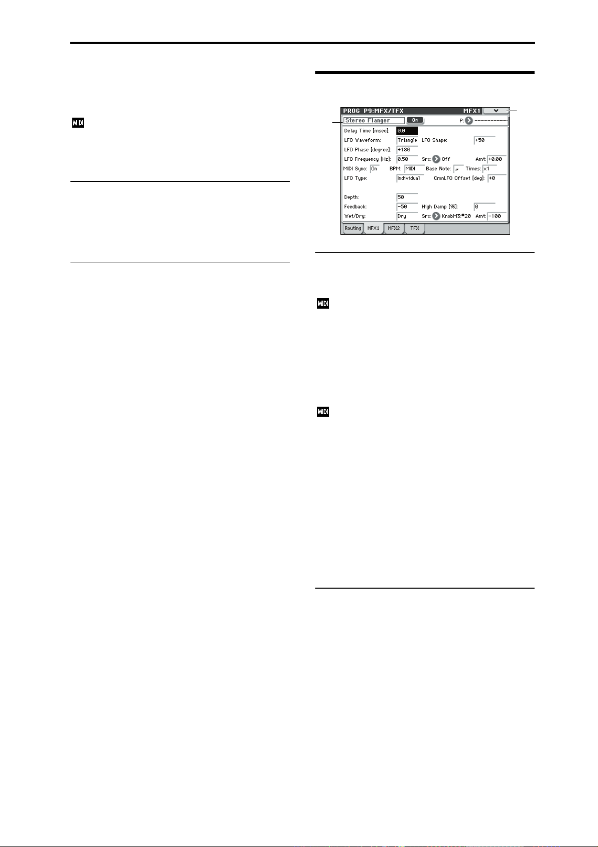
TFX On/Off [Off, On]
This turns total effect on/off. If this is off, the input will be
passed directly through. The setting will alternate between
on/off each time you press this.
Alternatively, you can send control change #95 to turn
the total effect off. A value of 0 turns the total effect off,
and values of 1–127 restore the original setting. The
global MIDI channel specified by MIDI Channel
(Global 1–1a) is used for this message.
9–1c: Master Volume
Master Volume [000...127]
This specifies the final level of the audio output that has
passed through total effect, and output from AUDIO
OUTPUT L/MONO and R.
PROG P9: MFX/TFX (Master/Total Effect) 9–2: MFX1
9–2: MFX1
9–2a
9–2
Menu
▼9–1: Menu Command
• 0: Write Program ☞p.73
• 1: Exclusive Solo ☞p. 73
•2: Copy Insert Effect ☞p.76
•3: Swap Insert Effect ☞p.76
• 4: Write FX Preset ☞p.77
For more information, please see “Program: Menu
Command” on page 73.
9–2a: MFX1
Here you can edit the parameters of the effect you choose for
MFX1 in the P9: MFX/TFX– Routing page.
Effect dynamic modulation (Dmod) is controlled on the
global MIDI Channel (Global 1–1a). For more
information, please see “Dynamic Modulation Source
List” on page 380.
MFX1 On/Off [Off, On]
This turns master effect 1 on/off. It is linked with the on/off
setting in the P9: MFX/TFX– Routing page.
The setting will alternate between On and Off each time you
press this.
Alternatively, you can use CC#94 to turn Master effects
1/2 off. CC#95 will turn the Total effect off. A value of 0
is Off, and a value of 1–127 selects the original setting.
This is controlled on the global MIDI channel specified
by MIDI Channel (Global 1–1a).
P (Effect Preset)
[P00, P01...15, U00...15, ---------------]
This selects the effect preset. For more information, please
see “P (Effect Preset)” on page 67.
MFX1 Parameters
Here, you can edit the parameters of the master effect
selected in the P9: MFX/TFX– Routing page.
For details on the master effects, please see “Master Effects
(MFX1, 2)” on page 281.
▼9–2: Menu Command
• 0: Write Program ☞p.73
• 1: Exclusive Solo ☞p. 73
• 2: Copy Insert Effect ☞p.76
• 3: Swap Insert Effect ☞p.76
• 4: Write FX Preset ☞p.77
For more information, please see “Program: Menu
Command” on page 73.
71
Page 80

Program mode
9–3: MFX2
9–4: TFX
These pages let you edit the parameters of Master Effect 2
and Total Effect. To select different effects types, use the P9:
MFX/TFX– Routing page.
The parameters for MFX2, TFX is the same as for MFX1. For
more information, please see “9–2: MFX1” on page 71.
72
Page 81
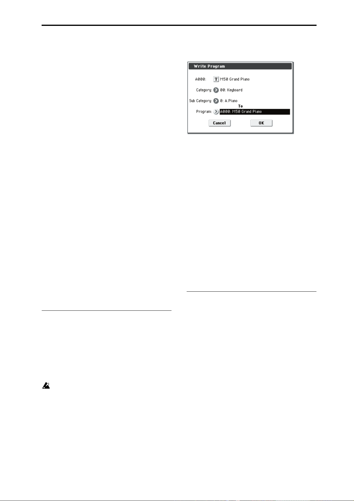
Program: Menu Command
ENTER + 0–9: shortcuts for menu commands
Each page has a set of menu commands, which provide
access to different utilities, commands, and options,
depending on the page you’re currently on. You can use the
menu commands entirely from the touch-screen, by pressing
the menu button in the upper right-hand corner of the
screen and then selecting an option from the menu that
appears.
Even though each page may have its own unique menu
commands, the menus are standardized as much as
possible. For instance, WRITE is almost always the first
menu item in Program, Combination, and Sequencer modes.
You can take advantage of this standardization by using a
shortcut to access any of the first ten menu items:
1. Hold down the ENTER switch.
2. Press a number (0–9) on the numeric keypad to select
the desired menu command, starting with 0.
For instance, press 0 for the first menu command, 1 for the
second, and so on.
If the menu command just toggles an option on and off
(such as Exclusive Solo), then you’re done. If the command
calls up a dialog box, the dialog will appear on the display,
and you can proceed just as if you’d selected the command
from the touch-screen.
Tip: While this command is open, the ENTER switch will
operate as the OK button and the EXIT switch will operate
as the Cancel button.
Procedure for menu commands
1. Select the menu command.
2. Make settings in the dialog box.
For details on the content of each dialog box, refer to the
explanation of each command.
3. To execute, press the OK button. To cancel without executing, press the Cancel button.
Write Program
This command writes an edited Program into the M50
internal memory. It is available on every page in Program
mode.
Write Program lets you:
• Save your edits
• Rename the Program
•Assign the Program to a Category
• Copy the Program to a different Bank and number
Be sure to Write any Program that you wish to keep. An
edited Program cannot be recovered if you do not write
it before turning off the power or selecting another
Program.
Program: Menu Command Write Program
1. The upper line of the dialog shows the Bank, number,
and Program name.
If you wish to modify the program name, press the text edit
button to move to the text edit dialog box, and enter the
desired program name.
2. In Category and Sub Category, specify the category of
the program that you are writing.
The category can be used to find this Program when
selecting a program in Program, Combination, or Sequencer
modes.
Note: You can edit these category names in the Global P4:
Category page. For more information, please see “4–1:
Program Main” and “4–2: Program Sub” on page 232.
3. Press “To Program” to specify the destination Bank and
number.
You can also use the BANK SELECT A–E switches to select a
bank.
Note: You can also use the SEQUENCER REC/WRITE
switch to write in the same way as Write Program. Press the
SEQUENCER REC/WRITE switch to access the dialog box
and write the program. In this case, the settings will be
saved to the currently selected program.
Exclusive Solo
The behavior of the Solo function will alternate each time
you select Exclusive Solo.
The Solo function can operate in one of the following two
ways.
•Multiple Solo
The specified OSC1, OSC2, or drum track will be soloed. The
solo on/off setting will alternate each time you press the
Solo button.
• Exclusive Solo
Only one source - OSC1, OSC2, or the drum track - will be
soloed.
Note: Solo operations can be performed in the P0–4: OSC/
DrumTrk Mixer page of each mode.
Note: The Solo function applies to each mode. All sources
are handled as a single group. In the case of Exclusive Solo,
all other sources will be off if even one source is being
soloed.
1. Use the menu to select Exclusive Solo.
When you select this item, a check mark will be added at the
left of Exclusive Solo in the menu. The check mark will
appear or disappear each time you select this item.
No check mark: Multiple Solo
Check mark: Exclusive Solo
Alternatively, you can turn this setting on/off by holding
down the ENTER switch and pressing numeric key 1.
73
Page 82

Program mode
Copy Tone Adjust
Tone Adjust tab of the play page.
This command replaces the current Tone Adjust settings
with those of any other Program, Combination Timbre, or
Song Track.
1. Use the From field to select the copy-source mode,
bank, and number.
You can use the front-panel BANK switches to select the
desired bank.
2. In the Timbre field (if you’ve selected a Combination)
or Track field (if you’ve selected a Song), select the Timbre or Track to copy from.
3. Select either All or Assignments Only to specify the
Tone Adjust parameters you want to copy.
All: This copies both the Tone Adjust parameter
assignments and values.
Assignments Only: This copies only the Tone Adjust
parameter assignments, without the values.
Reset Tone Adjust
Tone Adjust tab of the play page.
This command resets the Tone Adjust settings for all of the
displayed Switches and Sliders to their default values.
Copy Oscillator
Copy Oscillator is available on all of the tabs under the
Basic/Ctrls Controllers– Chord Trigger, OSC/Pitch, Filter,
Amp/EQ, AMS/C.KTrk pages.
This command is used to copy the settings from one
oscillator to another.
1. Use the From field to select the oscillator that you want
to copy.
2. Use Program to select the bank and number of the
copy-source program.
You can press a BANK SELECT switch to select the desired
bank.
3. In To, specify the copy destination oscillator.
Swap Oscillator
Swap Oscillator is available on all of the tabs under the
Basic/Ctrls Controllers– Chord Trigger, OSC/Pitch, Filter,
Amp/EQ, AMS/C.KTrk pages.
This command exchanges the settings of oscillators 1 and 2.
Note: This can be selected only if Oscillator Mode (Prog 1–
1a) is Double.
Copy Drum Track
Copy Drum Track is available on the DrumTrk Pattern tab
or DrumTrk Program tab of the ARP/DT.
This command copies settings from the specified program,
combination/timbre, or song.
1. Use the To field to specify how the Switches 1–8, Sliders 1–8, and Master Slider parameters will be reset.
All Off: All will be reset to Off.
Default Setting: The parameters will be reset to the default
values.
74
1. Use the From field to select the mode, bank, and number of the desired copy-source. You can press a BANK
switch to select the desired bank.
2. If you execute this command in Program mode, and
select Program in From, the additional field Program
Settings too will appear.
On (checked): The parameter settings of the Drum Track
Pattern page and Drum Track Program page will be copied.
Off (unchecked): The parameter settings of the Drum Track
Pattern page will be copied.
If you execute this command in Combination or Sequencer
mode, the parameter settings of the Drum Track Program
page will be copied. However, the MIDI Channel setting
will not be copied.
Page 83

Erase Drum Track Pattern
Erase Drum Track is available on the DrumTrk Pattern tab
or DrumTrk Program tab of the ARP/DT.
This erases the drum track pattern you specify.
1. Select the user drum track pattern you want to erase.
2. If you check All Drum Track Patterns, all user drum
track patterns will be erased.
Copy Chord Trigger Setup
Copy Chord Trigger Setup is available on the Chord Trigger
of Basic/Ctrls page.
This command copies the chord trigger switch settings of
the specified Program, Combination, or Song.
Program: Menu Command Erase Drum Track Pattern
2. If you no longer want the EGs to be synchronized,
select Sync Both EGs once again.
The indication will disappear from the display.
Swap LFO 1&2
Swap LFO 1 & 2 is available on all of the LFO pages, except
for the Common LFO tab.
This command copies the settings of LFO1 to LFO2, and
vice-versa.
Note: If LFO2 is being used to modulate LFO1, this
command will erase that modulation routing (since the
LFOs cannot modulate themselves).
After opening the dialog box, press the OK button to swap
the LFO settings, or press the Cancel button to close the
dialog box without making any changes.
Copy Arpeggiator
Copy Arpeggiator is available on the ARP Setup tab or Scan
Zone tab of the ARP/DT page.
This command can be used to copy arpeggio settings from
another location to the current program.
1. Use the From field to select the mode, bank, and number of the desired copy-source. You can also select
Banks via the front-panel BANK SELECT switches.
2. Select the copy-source switch number. If you want to
copy all settings for switches 1–4, check the All option.
3. Use the To field to specify the copy-destination switch.
Note: Executing this command will copy the note number
and velocity value. The MIDI channel is not copied.
Sync Both EGs
Sync Both EGs is available on the Filter 1/2 EG and Amp 1/
2 EG pages.
This option allows you to edit the EGs of Oscillator 1 and
Oscillator 2 together. When it is checked, editing the Filter
EG of either Oscillator 1 or 2 will change both Filter EGs
simultaneously. Similarly, editing the Amp EG of either
Oscillator will change both Amp EGs.
This option is available only when the Oscillator Mode is
set to Double.
1. Select Sync Both EGs.
The display will indicate “Sync,” and the two EGs will be
synchronized.
1. Use the From field specify the source of the arpeggio
settings (mode, bank, number) that you wish to copy.
2. If you are copying from Combination, or Song, specify
whether you wish to copy from A or B.
75
Page 84

Program mode
Copy Insert Effect
Copy Insert Effect is available on all of the IFX pages.
This command copies effects settings from within the
current Program, from other Programs, Combinations, or
Songs.
To execute the Copy Insert Effect command, press the OK
button. To cancel, press the Cancel button.
If you’re copying from a master effect, the result will
not be identical due to differences in the routing and
level settings of the master effects.
From (Mode)
This selects whether you’ll copy from a Program, a
Combination, a Song, or the current Sampling Mode
settings.
[Program, Combination, Song]
Swap Insert Effect
Swap Insert Effect is available on all of the IFX pages.
This command exchanges the effects, and their internal
parameters, between two IFX slots.
All of the parameters shown on the IFX 1–5 pages will be
copied.
Other IFX slot parameters will not be affected, including
Pan, Sends 1 and 2, Chain, AUX Bus, and FX Control Bus.
1. In Source 1 and Source 2, select each of the insert
effects that you wish to swap.
Copy MFX/TFX
Copy MFX/TFX is available on all of the MFX/TFX pages.
This command lets you copy any desired effect settings from
Program, Combination, or Song.
From (Bank and Number) [Bank and Number]
For Programs and Combinations, this selects the Bank and
Number from which to copy. When this parameter is
selected, you can also use the front-panel BANK buttons to
select Banks.
(Effects slot select) [IFX 1…5, MFX 1&2, TFX]
Select which of the effects you wish to copy.
You can also copy from a master effect and total effect.
All [check-box]
When this is enabled, the settings of all insert effects (the
contents of the Insert FX page and the effect parameters of
IFX1–5, but not Ctrl Ch) will be copied.
To [IFX 1…5]
This selects the insert effect copy destination.
Post IFX Mixer Settings [check-box]
When this is checked, the Pan, Bus (Bus Select), Ctrl (FX
Control Bus), and Sends 1 and 2 settings that follow the
copy source insert effect will also be copied.
When this is not checked, only the effect type and its
parameters will be copied.
Copying 000: No Effect
Copying a single effect set to “000: No Effect” will not work:
no data will be copied.
If either All or All used is selected, and “000: No Effect”
exists within a chain, it will be copied. However, if the entire
chain consists of “000: No Effect,” nothing will be copied.
1. Use the From field to select the copy source mode,
bank, and number.
You can also use the BANK SELECT switches to select the
desired bank.
2. Select the effect that you want to copy.
You can copy from an insert effect by selecting IFX1–5.
If you copy from an insert effect, the result may not be
exactly the same, due to differences in routing and level
settings.
If you select MFX1 or MFX2, the Return level will be copied
at the same time.
You can copy settings from a total effect by selecting TFX.
If you check All MFXs, all master effect settings will be
copied.
If you check TFX, all total effect settings will be copied.
Master Volume settings will not be copied.
3. In To, specify the copy destination master effects or
total effect.
76
Page 85

Swap MFX/TFX
Swap MFX/TFX is available on all of the MFX/TFX pages.
This command swaps (exchanges) settings between MFX1,
MFX2, TFX.
1. Use Source 1 and Source 2 to select the master effect(s)
or total effect(s) that you want to swap.
Write FX Preset
Write FX Preset is available on all of the effects parameter
editing pages, including IFX 1–5, MFX 1 and 2, and TFX.
This command saves the edited effect into the M50’s internal
memory.
Program: Menu Command Swap MFX/TFX
1. Press the text edit button to open the text edit dialog
box, and input a name for the effect preset.
2. Use the To field to select the writing destination. We
recommend that you use U00–U15.
77
Page 86

Program mode
78
Page 87

Combination mode
COMBI Page Select
• Press the MODE COMBI switch to select Combination
mode.
You can use the following ways to select the pages in
Combination mode.
1. Press the PAGE SELECT switch to access “Page Select.”
“Page Select” shows an abbreviated name for each page.
The page in which you were prior to pressing the PAGE
SELECT switch is shown in grey.
2. Select the desired page in the display.
Other ways to select pages
•Hold down the PAGE SELECT switch and press a
numeric keys, 0–9, to specify a page number; you will
move to the corresponding page.
For example if you want to access the P3: Timbre Param
page, hold down the PAGE SELECT switch and press
numeric key 3.
Note: For pages that consist of multiple subpages, such
as P5–1 and P5–2, or P8–1 and P8–2, the first of these
pages (P5–1 or P8–1) will be selected.
• You can press the EXIT switch to return to the P0: Play
page you selected most recently. Press the EXIT switch
once again to return to the Main page. Press the EXIT
switch to return to the P0: Play page.
Page Main content
Select and play combinations. (☞p.80)
Program selection for each timbre. (☞p.81)
Pan and volume settings etc. for each timbre.
P0: Play
PLAY
P1: Controllers
P2: EQ EQ settings for each timbre. (☞p.93)
P3: Timbre Param
EDIT
P4: Zone/Delay
P5–1:
MIDI Filter 1
P5–2:
MIDI Filter 2
P7: Arpeggiator/
Drum Track
ARP & DRUM TRACK
P8–1: IFX Route1/
1–5
P8–2: IFX Route2
EFFECT
P9: MFX/TFX
(☞p. 83)
Simple arpeggiator editing. (☞p. 84)
Editing from the Tone Adjust (☞p. 86)
Editing from the control surface. (☞p.87)
SW1, 2, and knob function settings. (☞p.91 )
Chord trigger switch note and velocity
settings (☞p. 92)
Various parameter settings for each timbre
(MIDI channel, OSC selection, Pitch setting,
etc.) (☞p.95)
Key split and layer settings.
(Key zone and velocity zone) (☞p.99)
Time delay from note-on to beginning of
sound. (☞p. 101)
MIDI transmit/receive filter 1 settings.
(☞p. 103)
MIDI transmit/receive filter 2 settings.
(☞p. 106)
Arpeggiator settings. (☞p.108)
Drum track settings. (☞p.111)
Oscillator output bus and master effect send
level settings. (☞p. 113)
Insert effect routing, selection, and settings.
(☞p. 115)
Bus settings for oscillator output. (☞p.117)
Common FX LFO 1, 2 settings (☞p.117)
Master effect routing, selection, and settings.
(☞p. 118)
Total effect selection and settings. (☞p. 119)
79
Page 88

Combination mode
COMBI P0: Play
This is the main page of Combination mode. Among other
things, you can:
• Select combinations
• Select a program for each timbre, and specify its Play/
Mute and Solo On/Off status.
• Edit the Arpeggiator in simple ways
•Use the Tone Adjust function to make simple edits for
program parameters
•Check the control surface content, and operate it.
Tip: Auto Song Setup
The Auto Song Setup feature copies the current Program or
Combination into a Song, and then puts the M50 in recordready mode.
If inspiration for a phrase or song strikes you while you’re
playing, you can use this function to start recording
immediately. To do so:
1. Hold down the ENTER switch and press the
SEQUENCER REC/WRITE switch.
The Setup to Record dialog box will open and ask “Are you
sure?”
2. Press OK.
You will automatically enter Sequencer mode, and will be in
the record-ready state.
3. Press the START/STOP switch to start the sequencer
and begin recording.
For more information, please see “Tip: Auto Song Setup” on
page 126.
0–1: Program T01–08, 0–2: Program T09–16
0–1
Menu
0–1a
0–1b
This is the main page for selecting and playing
Combinations. You can also set the Program, Play/Mute,
and Solo On/Off for each of the Timbres 1–8 and 9–16.
For more information, please see “0–1: Program T01–08, 0–2:
Program T09–16” on page 80.
0–1(2)a: Combination Select
Bank [A...D]
This indicates the currently selected combination bank.
Press one of the COMBI BANK A–D switches to select the
desired bank.
• Each bank contains rewritable combination program
areas for 128 combinations (a total of 1,792).
Bank No. Description
A, B, C 000…127 Preloaded combinations
D 000…127 User combinations
Note: Pressing one of the PROG BANK A–G switches while
the Program Select parameter is selected will change the
timbre program bank (rather than the combination bank).
Bank
Combination Select Popup Combination Select
Combination Select [000...127]
Here you can select the desired Combination.
To switch combinations
• Choose “Combination Select,” use numeric keys 0–9 to
input the desired combination number, and press the
ENTER switch.
• Choose “Combination Select” and turn the VALUE dial
or use the q/u switches.
Note: On this page only, the VALUE slider functions as a
modulation source - which means that you cannot use it
to select combinations.
• If the “0–1a: Combination Select” parameter is selected,
the PROG BANK A–D switches will switch combination
banks.
• From the Bank/Combination Select menu you can view
and select combinations by bank.
• From the Category/Combination Select menu you can
view and select combinations by category.
• You can use a foot switch to select combinations. For
more information, please see the Global parameter “Foot
Switch Assign” on page 228. For a list of the functions
that can be assigned to the footswitch, please see “Foot
Switch Assignments” on page 384.
• You can transmit MIDI program changes from a
connected external MIDI device.
Bank/Combination Select menu:
1. Press the popup button located at the left of “Combination Select” to access the Bank/Combination Select
menu.
2. Press one of the tabs at left or right to select a bank.
3. Select a combination from the list. You can directly
press your choice within the list, or use the qqqq/uuuu
switches.
If the screen cannot display all of the available items, use the
scroll bar.
Category Popup Tempo
80
Page 89
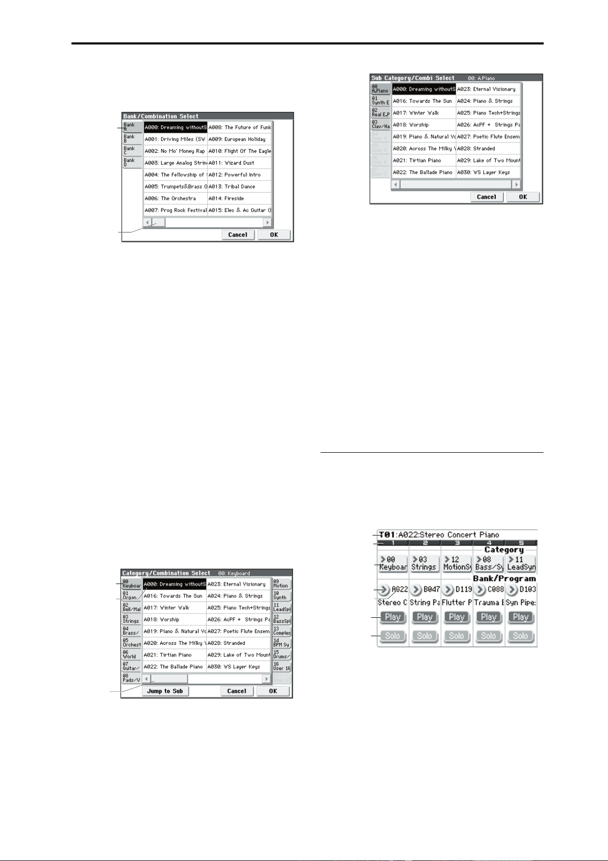
4. Press the OK button to execute, or press the Cancel button to cancel your selection.
Bank/Combination Select menu
Tab
Scroll bar
Category [00...17/00...07]
Here, you can select the combination category.
All programs are classified using eighteen main categories
and eight sub-categories. You can select a category, and then
select a combination within that category. When you press
the popup button, the Category/Combination Select menu
will appear.
Category/Combination Select menu:
You can select combinations by category and sub-category.
All combinations are organized into up to eighteen
categories, and each category is further organized into eight
sub-categories. You can use these categories and subcategories to select combinations.
1. Press the Category popup button (above the Combination Select parameter) to open the Category/Combination Select menu.
2. Press one of the tabs on the left and right to select the
desired category.
Note: You cannot select the category tab of a category to
which no combinations have been assigned.
3. Select a combination from the list. You can directly
press your choice within the list, or use the qqqq/uuuu
switches.
If there are more combinations than can be shown in the
screen, use the scroll bar to see the remaining combinations.
Category/Combination Select menu
Category
tab
Sub-category
tab
COMBI P0: Play 0–1: Program T01–08, 0–2: Program T09–16
5. Press the OK button to execute, or press the Cancel button to cancel your selection.
Note: The category of each combination can be specified in
the “Write Combination” dialog box.
(Tempo) [40.00... 300.00, EXT]
This is the tempo for the current Combination, which
applies to tempo-synced LFOs and effects, arpeggiator, and
tempo-synced effects.
040.00…300.00 allow you to set a specific tempo in BPM,
with 1/100 BPM accuracy. In addition to using the standard
data entry controls, you can use the TEMPO knob to adjust
the bpm, or just play a few quarter-notes on the TAP
TEMPO button.
If MIDI Clock (Global 1–1a) is set to External MIDI or
External USB, EXT is shown . This is also shown if “MIDI
Clock” is Auto and MIDI clock data is being received from
an external device. If tempo is EXT, arpeggiator etc. will
synchronize to MIDI clock data from an external MIDI
device. For more information, please see “MIDI Clock (MIDI
Clock Source)” on page 221.
0–1(2)b: Timbre Program Select
Selected Timbre Info
This area shows information on the timbre selected for
editing. T: Timbre number/program bank/number/name,
Ch: MIDI channel/number.
Select Timbre Info
Timbre No.
Category/Timbre
Program Select
Bank/Timbre
Program Select
Program Select
Play/Mute
Scroll bar
4. To select from a sub-category, press the Jump to Sub
button to access SubCategory/Program Select.
Press one of the left tabs to select a sub-category.
Note: Sub-categories not assigned to any programs cannot
be selected from the tabs.
Press the OK button to confirm your selection, or press the
Cancel button to cancel it. You will return to the main
categories.
Solo On/Off
Timbre Number
This indicates the timbre number. Below each timbre
number are shown various parameters which you can edit
for that timbre.
81
Page 90

Combination mode
Timbre 01 (Timbre Number):
Category (Timbre Program) [00...17/00...07]
Here, you can select the program used by each timbre by
program category and sub-category. All programs are
organized into up to eighteen categories and eight subcategories.
Press this popup button to get the Category/Program Select
menu, then select the desired category and sub-category,
and finally select the desired program.
Category/Timbre Program Select menu:
Here you can select the program for each timbre by main
category and sub-category. All programs are classified into a
maximum of eighteen main categories, and each category is
classified into eight sub-categories. You can select programs
using these main categories and sub-categories.
• Press Category and use the Category/Timbre Program
Select menu to select a program.
For the procedure, please see “Category/Combination
Select menu:,” above.
Program Select [A...E: 000...127,
GM, g(1)...g(9), g(d): 001...128]
Here, you can select the program used by each timbre. The
lower line displays part of the program name.
To switch the program of a timbre
• Choose Program Select, use numeric keys 0–9 to input
the program number, and press the ENTER switch.
• Choose Program Select and turn the VALUE dial,
VALUE slider or use the q/u switches.
• If the Program Select parameter is chosen, the PROG
BANK A–GM switches will switch program banks. (If
Timbre Program Select is selected, the BANK switch
LED of the program bank selected for that timbre will
light.)
• From the Bank/Program Select menu you can view and
select programs arranged by bank.
• From the Category/Program Select menu you can view
and select programs by category.
• You can choose a program by transmitting MIDI
program changes from a connected external MIDI
device.
When you select a Combination on the M50, a MIDI
program change for the selected combination number
will be transmitted on the global MIDI Channel
(Global 1–1a). At the same time, bank select, program
change, and volume (CC#7) messages will be
transmitted on the MIDI channel specified for each
timbre whose Status (Combi 3–1(2)c) is set to EXT or
EX2. However, these messages will not be transmitted
for timbres that are set to the same MIDI channel as the
global MIDI channel. In this case, EX2 timbres will
show the “Program” Bank as “–”, and will transmit the
bank number that was specified in Bank Select (When
Status=EX2) (Combi 3–1(2)c).
When you play on the M50 keyboard and controllers,
MIDI messages are transmitted on the global MIDI
channel. At the same time, timbres whose Status is set
to EXT or EX2 will transmit the same messages on their
own MIDI channel.
If bank select and program change messages are
received on a MIDI channel that matches the MIDI
channel of a timbre whose Status is INT, the program of
that timbre will change. However if the MIDI channel
of the incoming message matches the global MIDI
channel MIDI Channel, then the combination will
change.
If you do not want the combination to change, you can
either change the global MIDI channel to a MIDI
channel other than the channel on which the program
change messages are being received, or you can
uncheck Enable Combination Change (Global 1–2b).
You can also uncheck “Bank Change” so that only the
program number will change and the bank will remain
the same.
If you wish to change the program assigned to certain
timbres without changing the combination, you can
also set Enable Program Change (Combi 5–1–1(2)c) so
that the program will change on certain timbres but not
on others.
Bank/Timbre Program Select menu:
• Press the popup button located at the left of Program
Select, and choose a program from the Bank/Program
Select menu.
For the procedure, please see “Bank/Program Select menu:”
on page 2.
Play/Mute [Play, Mute]
This setting mutes a timbre.
Play: The timbre will produce sound.
Mute: The timbre will be muted (silent).
Solo On/Off [On, Off ]
Turns the Solo function on/off for each timbre.
The Solo function operates differently depending on the
setting of the Exclusive Solo menu command.
If Exclusive Solo is off, you can turn Solo on for more than
one timbre. The setting will alternate each time you press
the Solo On/Off button.
If Exclusive Solo is on, pressing a Solo button will turn Solo
on for only that timbre.
Note: The Solo On/Off status is not preserved when you
write the combination.
Exclusive Solo
The menu’s Exclusive Solo parameter also affects the way
that Solo works. When Exclusive Solo is Off (unchecked),
you can solo multiple Timbres at once.
When Exclusive Solo is On (checked), only one Timbre can
be soloed at a time. In this mode, pressing a Solo button
automatically disables any previous solos.
Tip: You can also toggle Exclusive Solo by holding ENTER
and pressing 1 on the numeric keypad.
Timbre 02...08, 09...16 (Timbre Number):
Here you can specify the program, Play/Mute status, and
Solo On/Off status for timbres 2–8 and 9–16. These are the
same as for timbre 01. For more information, please see
“Timbre 01 (Timbre Number):,” above.
▼0–1(2): Menu Command
• 0: Write Combination ☞p.120
•1: Exclusive Solo ☞p. 73
•2: Copy from Program ☞p. 120
For more information, please see “Combination: Menu
Command” on page 120.
82
Page 91
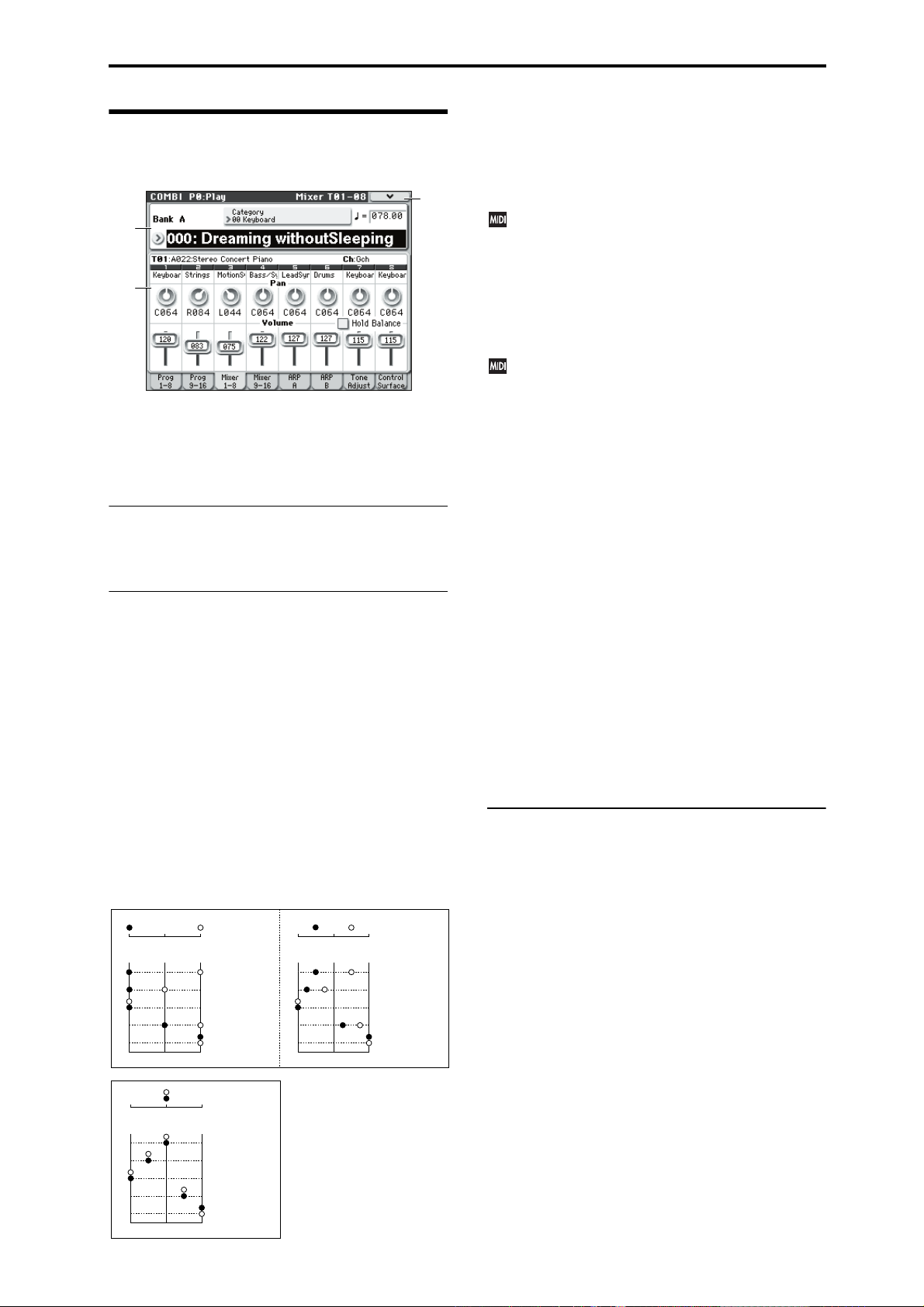
0–3: Mixer T01–08, 0–4: Mixer T09–16
0–3
Menu
0–3a
0–3b
This is the main page for selecting and playing
Combinations.
You can also set the pan, and volume for each of the Timbres
1–8 and 9–16. For more information, please see “0–1:
Program T01–08, 0–2: Program T09–16” on page 80.
0–3(4)a: Combination Select
For more information, please see “0–1(2)a: Combination
Select” on page 80.
COMBI P0: Play 0–3: Mixer T01–08, 0–4: Mixer T09–16
If a mono insert effect is in use, the settings you make here
will be ignored. In this case, the Pan: #8 parameter in P8–1:
IFX–Insert FX Setup page will adjust the panning of the
sound after the insert effect (“Mixer” on page 279).
RND: The oscillator pan will change randomly at each noteon.
If Status (Combi 3–1(2)c) is set to INT, CC#10 (pan)
messages can be received to control the setting. CC#10
values of 0 or 1 will place the sound at far left, 64 at
center, and 127 at far right. (exclude RND) Pan can be
controlled by messages received on the MIDI Channel
(Combi 3–1(2)c).
Volume [000...127]
Adjusts the volume of each timbre 1–8.
The volume of each timbre is determined by
multiplying this volume value with the MIDI volume
(CC#7) and expression (CC#11).
If Status (Combi 3–1(2)c) has been set to INT, incoming
MIDI CC#7 or CC#11 messages will control the volume
of a timbre. (However these messages will not affect the
setting of this parameter.)
If Status is EXT or EX2, the value of this parameter will
be transmitted as MIDI CC#7 when the combination is
changed. However this will not be transmitted by a
timbre that is set to the same MIDI channel as the global
MIDI channel. This message is transmitted on the
MIDI Channel (Combi 3–1(2)c) specified for each
timbre.
0–3(4)b: Pan, Volume
Selected Timbre Info
This area shows information on the timbre selected for
editing.
For more information, please see “0–1(2)b: Timbre Program
Select” on page 81.
Timbre 01 (Timbre Number):
Category [Category Name]
This indicates the category.
Pan [RND, L001...C064...R127]
This specifies the pan of each timbre.
L001…C064…R127: A setting of L001 is far left and R127 is
far right. A setting of C064 will reproduce the pan setting of
the Program mode.
OSC1
OSC2
OSC1:
Amp1 Pan=L001
Left
Center
Left
Center
Right
Right
OSC2:
Amp2 Pan=R127
Pan (CC#10)
C064
L032
L001
R096
R127
OSC1
OSC2
OSC1:
Amp1 Pan=L032
Left
Center
Left
Center
Right
Right
OSC2:
Amp2 Pan=R096
Pan (CC#10)
C064
L032
L001
R096
R127
Hold Balance [Off, On]
On (checked): When any one of the volume sliders is
moved, the volume of the other timbres will change as well.
The volume balance of timbres 1–16 will be maintained. This
is useful when you wish to adjust the overall volume.
Timbre 02...08 (Timbre Number):
Here you can specify the program etc. for each Timbre 2
through 8. These are the same as for timbre 01. For more
information, please see “Timbre 01 (Timbre Number):,”
above.
▼0–3(4): Menu Command
• 0: Write Combination ☞p.120
•1: Exclusive Solo ☞p. 73
•2: Copy from Program ☞p. 120
For more information, please see “Combination: Menu
Command” on page 120.
OSC1
Left
Left
Center
Center
OSC2
Right
Right
OSC1:
Amp1 Pan=C064
OSC2:
Amp2 Pan=C064
Pan (CC#10)
C064
L032
L001
R096
R127
83
Page 92

Combination mode
0–5: ARPEGGIATOR A, 0–6: ARPEGGIATOR B
0–5
Menu
0–5a
0–5b
0–5c
Here, you can make arpeggiator settings for the
combination. A combination can run two arpeggiators
simultaneously.
Arpeggiator parameters can be edited in P7: ARP/DT, but
certain major parameters can be edited in these pages as
well. You can edit these parameters in realtime, for example,
by changing the arpeggio pattern while playing in Combi
P0: Play.
You can also use the TEMPO knob and the control surface
arpeggio control (ARP) GATE knob, VELOCITY knob,
LENGTH knob, and OCTAVE knob to control the
arpeggiator in realtime.
To save the edits you make, use Write Combination.
0–5(6)c: Arpeggiator A (B)
Pat (Pattern)
Octave [1, 2, 3, 4]
Reso (Resolution) [ , , , , , ]
Sort [Off, On]
Latch [Off, On]
Key Sync. [Off, On]
Keyboard [Off, On]
Set the various parameters of the combination arpeggiator.
For more information, please see “COMBI P7: Arpeggiator/
Drum Track” on page 107.
These parameters can also be set from 7–3(4): Arpeggiator
A(B) Setup.
[P0...P4, U0000(INT)...U0899(INT),
U0900(USER)...U1027(USER)]
▼0–5(6): Menu Command
• 0: Write Combination ☞p.120
• 1: Exclusive Solo ☞p. 73
• 2: Copy from Program ☞p. 120
• 3: Copy Arpeggiator ☞p. 122
For more information, please see “Combination: Menu
Command” on page 120.
0–5(6)a: Combination Select, Tempo
Bank, Combination Number & Name
These are the bank, number, and name of the current
Combination. Here, you can also select a combination.
For more information, please see “0–1(2)a: Combination
Select” on page 80.
(Tempo) [040.00...300.00, EXT]
For more information, please see “ (Tempo)” on page 81.
0–5(6)b: Arpeggiator Run A/B,
Timbre assign
Arpeggiator Run A, B
When the ARP ON/OFF switch is on, the arpeggiator(s) you
checked here will run if they are assigned to a timbre by
Arpeggiator Assign (7–1(2)c).
When the arpeggiator is on, these check boxes let you turn A
and B on/off.
This parameter can also be set from P7: Arpeggiator/Drum
Track page Arpeggiator Run A, B.
Timbre assign
This indicates the arpeggiator A and B assignment status for
each timbre 1–8. These settings are made in Arpeggiator
Assign (7–1(2)c).
84
Page 93

COMBI P0: Play Tone Adjust
Tone Adjust
0–7
0–7a
0–7b
0–7c
Tone Adjust provides two important features
simultaneously:
• You can use the Tone Adjust parameters to edit the most
important program parameters.
•It lets you modify Programs for use within a specific
Combination including everything from subtle tweaks
(like changing LFO speeds) to dramatic changes (such as
selecting a different Multisample). Any changes that you
make are stored with the Combination, and do not alter
the original Program.
Each of the sixteen Timbres has its own set of tone adjust
parameters.
For more information, see:
•“Absolute (Abs), Relative (Rel), Meta parameter” on
page 6
•“Tone Adjust and MIDI SysEx” on page 7
•“Interaction between Tone Adjust and MIDI CCs” on
page 7
Menu
0–7b: Timbre select, Selected parameter
information
Timbre select
Timbre [1…16]
This selects the timbre that will be controlled via the Tone
Adjust parameters. You can switch back and forth between
the different timbres as much as you like, without losing
your edits.
Auto Load (Auto Load PRG) [Off, On]
When you first load a Program into a Timbre, this parameter
determines whether or not the Program’s Tone Adjust
settings will be loaded as well.
The parameter settings assigned to the sliders and switches
in the display and the on/off settings assigned to the
Absolute parameters will be loaded.
Once the Program has been loaded, you can change any or
all of the Tone Adjust settings as desired, including both
assignments and values. All such edits are stored in the
Combination, without affecting the original Program.
If Auto Load PRG is On, Tone Adjust settings will be
automatically loaded along with the Program.
If Auto Load PRG is Off, the Tone Adjust settings of the
replacement program will not be loaded; the program
settings prior to replacement will remain.
Selected parameter information
This status line shows detailed, read-only information about
the currently selected Tone Adjust parameter.
Control Assignment Value Stored ValueType
Saving Tone Adjust Edits
In Program mode, when you make edits via Tone Adjust
and then save the results, the Program data is changed–just
as if you’d edited the internal parameters directly. For more
information, please see “Saving Tone Adjust Edits” on
page 7.
In Combination mode, however, all Tone Adjust edits are
stored within the Combination; the Program itself is not
changed. This lets you alter the way that a Program sounds
in one specific Combi without affecting the way that it
sounds in Program mode, or in any other Combinations or
Songs.
0–7a: Combination Select, Tempo
Bank, Combination Number & Name
These are the bank, number, and name of the current
Combination. Here you can also select a combination.
For more information, please see “0–1(2)a: Combination
Select” on page 80.
(Tempo) [040.00...300.00, EXT]
For more information, please see “ (Tempo)” on page 81.
Control [SW1…8, SL1…8]
This is the switch or slider in the display that is assigned to
Tone Adjust parameters.
Assignment [List of Tone Adjust assignments]
This is the full name of the parameter assigned to the switch
or slider in the display. You can change this using the
“Assign” parameter, below.
Value
This shows the current value of the parameter. The range of
values will vary depending on the parameter assigned to the
switch or slider.
Type [Rel, Abs, Meta]
This shows the type of the parameter, which relates to how
edits to the parameter are saved. For more information,
please see “Absolute (Abs), Relative (Rel), Meta parameter”
on page 6.
Stored Value
This shows the original value of the parameter, before the
effects of Tone Adjust. It applies only to Tone Adjust
parameters which control a single Program parameter.
If you un-assign a parameter from a control, it will revert to
this value.
85
Page 94
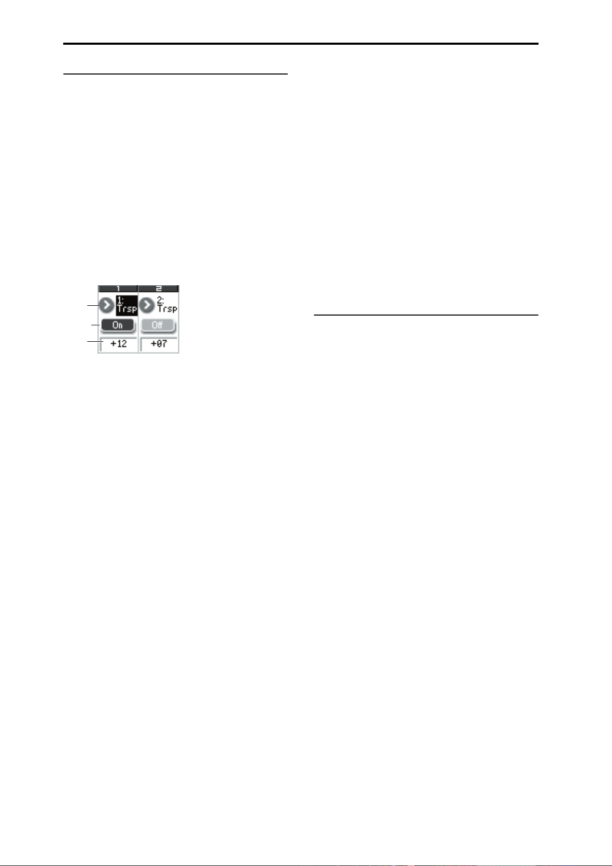
Combination mode
0–7c: Tone Adjust
Here, you can assign Tone Adjust parameters to the switches
and sliders in the display.
Switches 1...8
Tone Adjust switches act a little differently than switches in
the display.
When a switch is assigned to a Relative parameter, or an
Absolute parameter with more than two states:
Switch On = On Value (see below)
Switch Off = the Program’s stored value
When a switch is assigned to a two-state Absolute
parameter, such as Hold, the switch status directly reflects
the parameter value:
Switch On = On
Switch Off = Off
Assign
On/Off
Value
Assign
This assigns Tone Adjust parameters to the switches in the
display. For a full list of the available choices, please see
“Common Tone Adjust Parameters” on page 8 and “Tone
Adjust Parameters” on page 9.
On Value [Depends on parameter]
The parameter is set to this value when the switch is On.
When the switch is assigned to a two-state Absolute
parameter, such as Hold, this will always be the same as the
Switch Status (see below).
Sliders 1–8
Assign
This assigns Tone Adjust parameters to the sliders in the
display. For a full list of the available choices, please see
“Common Tone Adjust Parameters” on page 8 and “Tone
Adjust Parameters” on page 9.
Assignments are exclusive
Per-Oscillator parameters apply to OSC1 and 2 individually,
and are marked as such: OSC1 and OSC2.
Each slider can be assigned to only one parameter, and each
parameter can be assigned to only one slider.
To swap a parameter from one slider to another, you’ll need
to first un-assign it from the old slider, and then assign it to
the new slider.
Value
This shows the current value of the parameter. The range of
values will vary depending on the parameter assigned to the
slider.
▼0–7: Menu Command
• 0: Write Combination ☞p.120
• 1: Exclusive Solo ☞p. 73
• 2: Copy from Program ☞p. 120
• 3: Copy Tone Adjust ☞p. 121
• 4: Reset Tone Adjust ☞p. 122
For more information, please see “Combination: Menu
Command” on page 120.
Switch Status [Off, On]
This simply shows whether the switch is On or Off.
86
Page 95
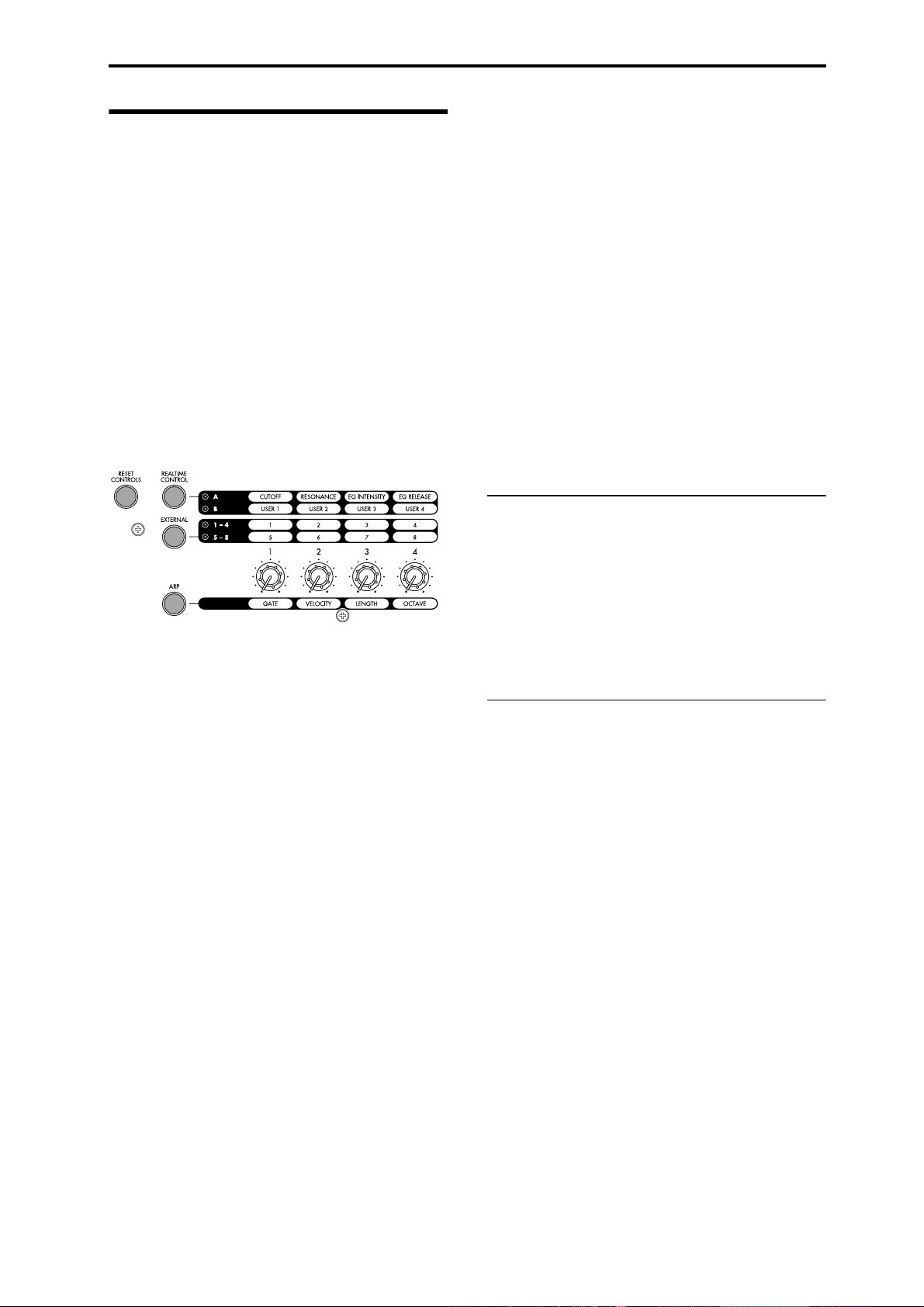
0–8: Control Surface
The control surface consists of the four knobs located in the
left side of the front panel and the four switches to their left.
You can use this control surface in a variety of ways, such as
editing the sound, controlling the arpeggiator, or
transmitting MIDI messages to external devices.
This page shows you the current values for each of the
knobs, along with information about what they are
controlling. For instance, you can:
•Use the knobs to modulate sounds and effects
•Use the knobs to transmit MIDI messages
•Use the knobs to control arpeggiator
CONTROL ASSIGN switches and parameters
You can use Control Assign in the display or the front panel
REALTIME CONTROL, EXTERNAL, ARP switches to
switch the function of control surface. Since the display and
the front panel switches are linked, changing one will
change the other correspondingly.
COMBI P0: Play 0–8: Control Surface
Resetting a group of controls
1. Use the display’s Control Assign or the front panel
CONTROL ASSIGN switches to access the controllers
you want to reset.
Note: As a safety precaution, you can only reset the
parameters currently displayed on the Control Surface.
If you want to reset filter settings etc., press the CONTROL
ASSIGN REALTIME CONTROL switch to select A.
2. Hold down the RESET CONTROLS switch.
3. While holding down RESET CONTROLS, press the
current CONTROL ASSIGN switch again.
All knobs shown in the control surface will be reset to their
default values.
Resetting Arpeggiator parameters
You can also perform the following reset operations for
Arpeggiator.
To reset the knobs of each arpeggiator, hold down the
RESET CONTROLS switch and press the ARP switch. The
arpeggiator will be reset to the values stored in the
combination.
In Combination mode, you can select one of three different
functions:
Realtime Control: Use the knobs to control the sound or
effects.
External lets you send MIDI messages to external MIDI
devices. Use the Global P1: MIDI– External Mode 1/2 page
to specify the MIDI message that will be transmitted.
ARP: Use the knobs to control the Arpeggiator function.
You can freely change back and forth between the different
functions, without losing any of your edits.
Reset controls
The front panel RESET CONTROLS switch lets you return
the desired knobs of the control surface to their saved
values. You can also use this to reset the Arpeggiator
settings.
Resetting a single control
To reset individual knob:
1. Hold down the RESET CONTROLS switch.
2. While holding down RESET CONTROLS, move a
knob, or press one of the control surface buttons.
The knob will be reset to the value stored in the Program.
3. When you’re done, release the RESET CONTROLS
switch.
0–8a: Combination Select, Tempo
Bank (Bank Select) [A...D]
Program Select [0...127]
(Tempo) [040.00...300.00, EXT]
This area displays information about the program selected
for editing – the program bank/number/ name, and the
tempo used to control the arpeggiator etc.
For more information, please see “0–1(2)a: Combination
Select” on page 80.
0–8b: Control Assign
Control Assign [Realtime Control, External, ARP]
This selects the items that will be affected by the control
surface. You can also press one of the CONTROL ASSIGN
switches to make this selection.
For details on each selection, please see the explanations that
follow.
87
Page 96

Combination mode
Realtime Control
0–8a
0–8b
0–8
Menu
CC parameter scaling
99
Parameter
Value
As Programmed
0–8c
Realtime Control lets you use the four knobs to edit the
parameters of a combination or effect.
There are two modes of realtime control: A and B. These two
modes will alternate each time you press the REALTIME
CONTROL switch. In each mode, you can use knobs 1–4 to
control parameters. Your selection of mode is remembered
independently for each combination. If you switch to a
different control surface function, and then press the
REALTIME CONTROL switch to return to realtime control,
the mode you had selected will still be active.
In A mode, the functions assigned to knobs 1–4 are fixed. In
B mode, you can assign a variety of modulation functions to
knobs 1–4. To assign functions, use the P1: Controllers Setup
page (page 91).
0–8b: Control Assign, RTC Knob Mode,
Selected Parameter Information
Control Assign [Realtime Control, External, ARP]
This selects the items that will be controlled by the control
surface.
RTC Knob Mode [A, B]
Selects either A or B as the realtime control mode for the
knobs. You can also use the front panel REALTIME
CONTROL switch to make this selection.
00
640 127
CC Value
Knob 1–A: Flt Fc (Cut Off) [000...127]
This knob scales the cutoff frequencies of Filters A and B,
and transmits and receives MIDI CC #74.
Knob 2–A: Flt Reso (Resonance) [000...127]
This knob scales the resonance of Filters A and B, and
transmits and receives MIDI CC #71.
Knob 3–A: Flt EG (Filter EG Intensity) [000...127]
This knob scales the effect of the Filter EG on the cutoff
frequencies of Filters A and B. It also transmits and receives
MIDI CC#79.
Knob 4–A: EG Rel (EG Release) [000...127]
This knob scales the release time of the Filter and Amp EGs,
and transmits and receives MIDI CC#72.
Knob 1…4–B [000...127]
These are the current values and assigned functions (MIDI
CC) for the Realtime Control B mode knobs.
In the P1: Controllers– Controllers Setup page you can
assign a variety of modulation functions to Realtime Control
B mode knobs 1–4.
Many of the functions scale a particular set of Program
parameters. All of the settings also correspond to MIDI
messages–usually CCs.
Selected Parameter information
When you select a knob, this area shows detailed
information about its parameter assignments.
0–8c: Realtime Control
The Realtime Control A mode knob functions (CUTOFF –
EG RELEASE) are fixed. You can assign a variety of
functions to Realtime Control B mode knobs 1–4 (Knob1B –
Knob4B). MIDI control changes are assigned for each
function.
When you move a knob, it sends out the corresponding
MIDI CC.
This will control timbres on the global MIDI channel.
Most of these functions adjust (scale) the parameter settings
of the timbre programs. Unless otherwise noted, “scaling”
means that the parameters are at their programmed values
when the controller is at 64, at their minimum when the
controller is at 0, and at their maximum when the controller
is at 127. For another look at this, please see the diagram
below.
88
Page 97

COMBI P0: Play External
u
External
0–8
0–8a
0–8b
0–8d
This External control lets you transmit MIDI messages to
external devices.
There are two modes of external control: EXT 1–4 and EXT
5–8. These two modes will alternate each time you press the
EXTERNAL switch. In each mode, the MIDI CC# assigned
to each knob will be transmitted on the MIDI channel when
you operate knobs 1–4.
You can also assign a note or MIDI CC# for transmission on
a specified MIDI channel to the chord trigger switches. (See
“1–3: External Mode 1” on page 224 and “1–4: External
Mode 2”)
You can create 128 different external setups in the Global P1:
MIDI– External Mode 1, 2 pages. For instance, you might
make one setup for controlling several different pieces of
MIDI gear on stage, another for controlling a software
synthesizer (such as one of Korg’s Legacy Collection
synths), and so on.
These External Setups are completely separate from the
Program. You can think of External mode as being a
separate control surface which just happens to share M50’s
knobs, and chord trigger switches.
When you select an External Setup, it stays selected even
when you change Programs, or switch to Combination or
Sequencer modes. This makes it easy to select different M50
sounds without disrupting any external MIDI control, and
vice-versa.
Men
0–8d: External
MIDI Channel [01…16, G]
This read-only parameter shows the MIDI Channel for the
knob. Each can send on a different channel, if desired.
G means that the slider will transmit on the Global MIDI
Channel, as set in Global mode.
CC# Assign [Off, 000…119]
This read-only parameter shows the MIDI CC sent by the
knob.
Value [000…127]
This is the current value of the knob’s MIDI CC.
0–8b: Control Assign, Ext Knob Mode,
Setup
Control Assign [Realtime Control, External, ARP]
This selects the items that will be affected by the control
surface.
Ext Knob Mode [1–4, 5–8]
Selects either EXT 1–4 or EXT 5–8 as the external control
mode for the knobs. You can also use the front panel
EXTERNAL switch to make this selection.
Setup [000…127]
This selects the Global setup for the knobs, and chord trigger
switches.
Note: Your selection here is remembered in internal
memory; it is not saved for each combination. When you
press the EXTERNAL switch to select external control, the
previously-selected external setup will be active.
89
Page 98

Combination mode
ARP
0–8
0–8a
0–8b
0–8e
Arpeggio control lets you use the four knobs to control the
two arpeggiators in realtime.
0–8b: Control Assign
Control Assign [Realtime Control, External, ARP]
This selects the items that will be affected by the control
surface.
Menu
0–8e: Arpeggiator
The functions of knobs 1–4 are fixed. The knobs will control
the duration of the arpeggiated notes, their velocity, the
pitch range, and the length of the arpeggio pattern.
Knob 1: Gate [–64...+00...+64]
Adjusts the duration (gate time) of the arpeggiated notes
(See “Gate” on page 60).
Knob 2: Velocity [–64...+00...+64]
Adjusts the velocity of the arpeggiated notes (See “Velocity”
on page 60).
Knob 3: Length [–64...+00...+64]
Adjusts the length of the arpeggio pattern.
Knob 4: Octave [–64...+00...+64]
Adjusts the pitch range over which the arpeggiator will play,
in one-octave steps (See “Octave*” on page 59).
If Arpeggio Tone Mode is set to Fixed Note, operating
knob 4 will not affect the pitch range.
▼0–8: Menu Command
• 0: Write Combination ☞p.120
• 1: Exclusive Solo ☞p. 73
•2: Copy from Program ☞p. 120
For more information, please see “Combination: Menu
Command” on page 120.
90
Page 99

COMBI P1: Controllers
COMBI P1: Controllers 1–1: Controllers Setup
1–1: Controllers Setup
1–1
1–1a
1–1b
1–1c
Here, you can assign the functions performed by SW1 and
SW2, and by knobs 1–4 when control surface REALTIME
CONTROL B mode is selected.
Note: SW1 and SW2 can be controlled by the SW1 and SW2
switches.
Note: The Panel Switch Assign setting of the program
assigned to each timbre will have no effect.
1–1a: Combination, Tempo
Bank, Combination Number & Name
These are the bank, number, and name of the current
Combination.
For more information, please see “0–1(2)a: Combination
Select” on page 80.
Menu
1–1c: Realtime Control Knob Assign
Here you can select the functions (mainly types of control
change) that are assigned to knobs 1–4 when the control
surface REALTIME CONTROL switch has selected B mode.
(See “Realtime Control Knobs 1–4 Assignments” on
page 383)
The functions you assign here are active when you use the
CONTROL ASSIGN REALTIME CONTROL switch to select
B mode, and operate knobs 1–4.
Knob 1–B [Off, ..., MIDI CC#119]
Knob 2–B [Off, ..., MIDI CC#119]
Knob 3–B [Off, ..., MIDI CC#119]
Knob 4–B [Off, ..., MIDI CC#119]
▼1–1: Menu Command
• 0: Write Combination ☞p.120
• 1: Exclusive Solo ☞p. 73
•2: Copy from Program ☞p. 120
For more information, please see “Combination: Menu
Command” on page 120.
(Tempo) [040.00...300.00, EXT]
For more information, please see “ (Tempo)” on page 81.
1–1b: Panel Switch Assign
SW (SW1 Assign) [Off, ..., JS-Y Lock]
This assigns the function of SW1. For more information,
please see “List of SW 1/2 assignments” on page 382.
Note: If the on/off status of the front panel SW1, SW2
switches is memorized when you save the combination.
If you change the function setting, the status is reset to off.
Mode (SW1 Mode) [Toggle, Momentary]
This specifies the on/off operation when you press the SW1
switch.
Toggle: The state will alternate between On and Off each
time you press the SW1 switch.
Momentary: The state will remain On only while you
continue holding down the SW1 switch.
SW2 (SW2 Assign) [Off, ..., JS-Y Lock]
Mode (SW2 Mode) [Toggle, Momentary]
This assigns the function of SW2. The functions that can be
assigned to SW2 are the same as for SW1, with the
substitution of SW2 Mod. (CC#81) instead of the SW1’s SW1
Mod. (CC#80).
91
Page 100
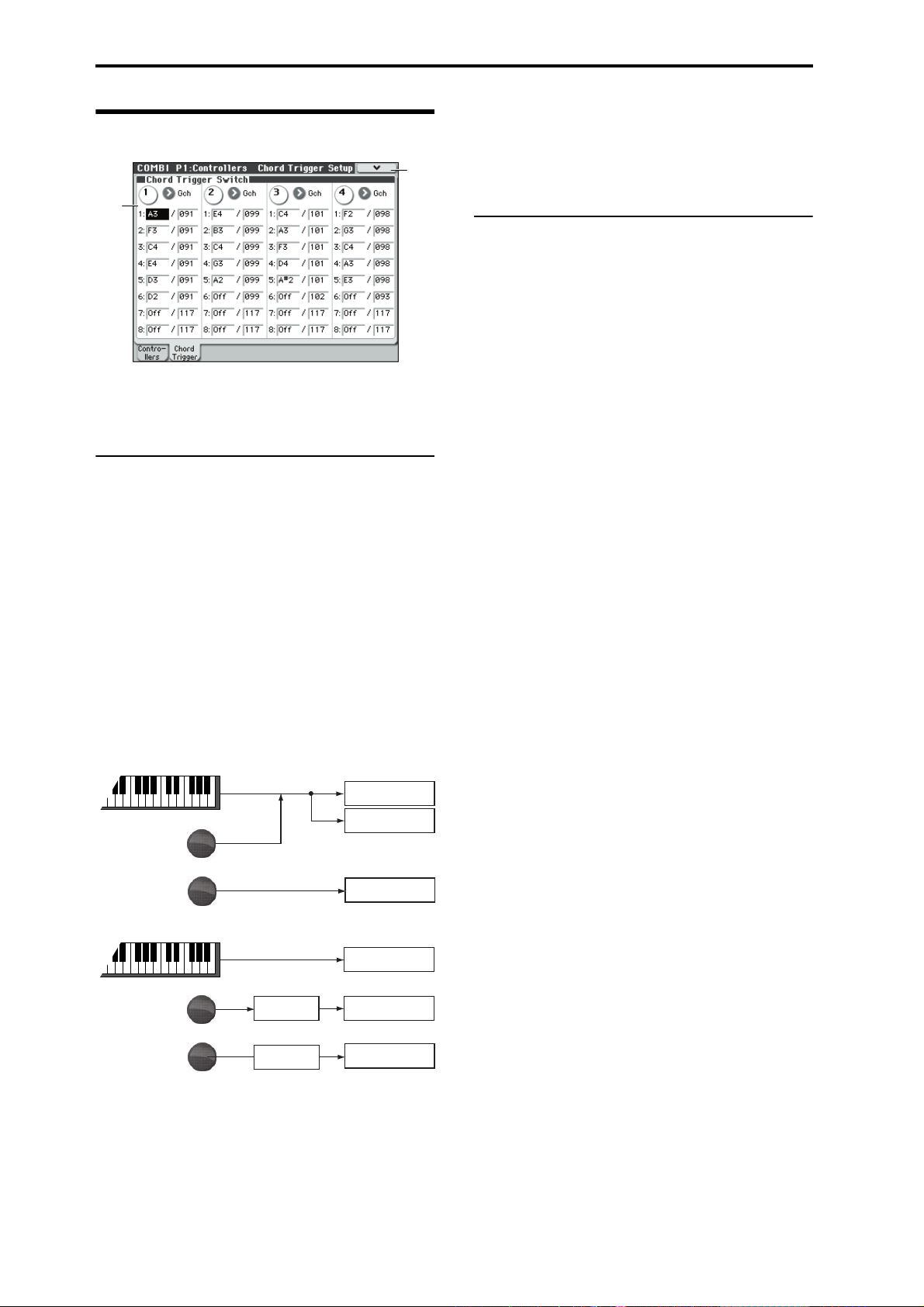
Combination mode
1–2: Chord Trigger Setup
For more detailed instructions, please see “1–8a: Chord
Trigger Switches” on page 20.
1–2
Menu
1–2a
For each combination, you can assign the note numbers and
velocities that will be produced by chord trigger switches 1–
4. You can assign up to eight note numbers and their
velocity for each chord trigger switch.
1–2a: Chord Trigger Switch
SW 1:
MIDI Channel [Ch01...Ch16, Gch]
This sets the chord trigger switch’s MIDI output channel.
You can set this to either a specific channel (1–16), or the
Global MIDI Channel.
Ch01…Ch16: The switch will transmit on the selected MIDI
channel. As shown in the diagram below, you can:
Use this in conjunction with the Timbre MIDI Channel
(Combi 3–1(1)c) setting, to route a swicth to a specific
Timbre. For more information, please see “MIDI Channel”
on page 95.
Gch: Use the global MIDI Channel setting. This is the
default. For more information, please see “MIDI Channel
(Global MIDI Channel)” on page 220.
Gch
T01: Piano
Gch
SW 2...4
These are the same as for SW 1, as described above.
▼1–2: Menu Command
• 0: Write Combination ☞p.120
• 1: Exclusive Solo ☞p. 73
•2: Copy from Program ☞p. 120
•3: Copy Chord Trigger Setup ☞p. 75
For more information, please see “Combination: Menu
Command” on page 120.
1
Gch
SW1
2
2ch
2ch
SW2
Gch
2ch
3ch
3ch
1
SW1
2
SW2
Arpeggiator A
Arpeggiator B
Notes 1…8 [Off, C–1…G9 / 001…127]
These parameters let you edit the 8 notes assigned to each
switch, along with a separate velocity for each note. To play
fewer than 8 notes, just set the unwanted notes to Off.
Off: Select this to disable the note.
C–1…G9: This sets the note number.
001…127: This sets the note’s velocity value.
92
T02: Strings
T03: Bell
T01: Piano
T02: Strings
T03: Bell
Gch
2ch
Gch
2ch
3ch
 Loading...