

Page 1
6E
Operation Guide
Page 2
About this manual
Thank you for purchasing the Korg KROME Music Workstation. To help you get the most out of your new
instrument, please read this manual carefully.
The manuals and how to use them
The KROME comes with the following manuals.
• Video Manual (approximately 60 minutes)
•Quick Start Guide (printed and PDF)
•Operation Guide (PDF)
• Parameter Guide (PDF)
• Voice Name List (PDF)
All of these manuals are on the included accessory disc.
A printed copy is included only for the Quick Start
Guide.
Video Manual
This video illustrates the main functionality of the
KROME.
Quick Start Guide
This provides a simple explanation of the KROME’s
functions. To begin, please watch the Video Manual and
read the Quick Start Guide.
Operation Guide
Put simply, the Operation Guide is designed to answer
the question, “How do I do this?”
It explains the names and functions of each part of the
KROME, basic operation, an overview of each mode,
how to edit sounds, record on the sequencer, and so on.
This guide also explains the basics of effects, the
Arpeggiator, Drum Track, and Drum Kits.
Finally, it also contains a troubleshooting guide as well as
supplemental information such as a list of specifications.
Parameter Guide
The Parameter Guide is designed to answer the question,
“What does this do?”
Organized by mode and page, the Parameter Guide
includes information on each and every parameter in the
KROME.
Voice Name List
The Voice Name List lists all of the sounds and setups
that are in the KROME when it is shipped from the
factory, including Programs, Combinations,
Multisamples, Drumsamples, Drum Kits, Arpeggio
Patterns, Drum Track Patterns, Template Songs, and
Effect Presets.
PDF versions
The KROME PDF manuals are designed for easy
navigation and searching. They include extensive PDF
contents information, which generally appears on the
side of the window in your PDF reader and lets you jump
quickly to a specific section. All cross-references are
hyper-links, so that clicking on them automatically takes
you to the source of the reference.
Conventions in this manual
References to the KROME
The KROME is available in 88-key, 73-key, and 61-key
models. The manuals refer to all models without
distinction as “the KROME.” The front panel and rear
panel illustrations in the manual show the 61-key model,
but they apply identically to the other models.
Abbreviations for the manuals: QS, OG, PG,
VNL
In the documentation, references to the manuals are
abbreviated as follows.
QS: Quick Start Guide
OG: Operation Guide
PG: Parameter Guide
VNL: The Voice Name List
Symbols , , Note, Tips
These symbols respectively indicate a caution, a MIDIrelated explanation, a supplementary note, or a tip.
Example screen displays
The parameter values shown in the example screens of
this manual are only for explanatory purposes, and may
not necessary match the values that appear in the Display
of your instrument.
MIDI-related explanations
CC# is an abbreviation for Control Change Number.
In explanations of MIDI messages, numbers in square
brackets [ ] always indicate hexadecimal numbers.
What is REMs * ?
(Resonant structure and Electronic circuit
Modeling System) is Korg’s proprietary technology for
digitally recreating the numerous factors that produce
and influence a sound, ranging from the soundproduction mechanisms of acoustic instruments and
electric/electronic musical instruments, to the resonances
of an instrument body or speaker cabinet, the sound field
in which the instrument is played, the propagation route
of the sound, the electrical and acoustic response of mics
and speakers, and the changes produced by vacuum
tubes and transistors.
* All product names and company names are the
trademarks or registered trademarks of their respective
owners.
ii
Page 3

Table of Contents
About this manual . . . . . . . . . . . . . . . . . . . . . . . . . . . ii
Introduction to the KROME . . . . . . . . . . . . 1
Front and rear panels. . . . . . . . . . . . . . . . . . . . . . . . . 1
Front panel . . . . . . . . . . . . . . . . . . . . . . . . . . . . . . . . . . . . . . . 1
Rear panel . . . . . . . . . . . . . . . . . . . . . . . . . . . . . . . . . . . . . . . .3
Objects in the display . . . . . . . . . . . . . . . . . . . . . . . . . . . . . 4
Basic Information . . . . . . . . . . . . . . . . . . . . . . . . . . . . 7
About the KROME’s modes . . . . . . . . . . . . . . . . . . . . . . . .7
Basic operations . . . . . . . . . . . . . . . . . . . . . . . . . . . . . . . . . .9
Setup . . . . . . . . . . . . . . . . . . . . . . . . . . . . . . .15
Turning the power on/off . . . . . . . . . . . . . . . . . . . . 15
Connecting the AC adapter. . . . . . . . . . . . . . . . . . . . . . .15
Turning the power on . . . . . . . . . . . . . . . . . . . . . . . . . . . .15
Turning the power off . . . . . . . . . . . . . . . . . . . . . . . . . . . .15
Connections . . . . . . . . . . . . . . . . . . . . . . . . . . . . . . . . 17
Audio connections . . . . . . . . . . . . . . . . . . . . . . . . . . . . . . .18
Connecting a damper pedal, foot switch, or foot
pedal. . . . . . . . . . . . . . . . . . . . . . . . . . . . . . . . . . . . . . . . .18
Connecting the KROME to a computer. . . . . . . . . . . .20
Connecting MIDI devices . . . . . . . . . . . . . . . . . . . . . . . . .20
Playing and editing Programs . . . . . . . . 21
Effects . . . . . . . . . . . . . . . . . . . . . . . . . . . . . . . . . . . . . . . . . . . 42
Automatically importing a Program
into Sequence mode . . . . . . . . . . . . . . . . . . . . . . . . . 42
Playing and editing Combinations . . . .43
Playing combinations . . . . . . . . . . . . . . . . . . . . . . . 43
Selecting Combinations. . . . . . . . . . . . . . . . . . . . . . . . . . 43
Using controllers to modify the sound . . . . . . . . . . . . 45
Performing with the arpeggiator or drum track . . . 45
Easy Combination editing. . . . . . . . . . . . . . . . . . . . 46
Changing the program of each timbre. . . . . . . . . . . . 46
Adjusting the mix . . . . . . . . . . . . . . . . . . . . . . . . . . . . . . . . 46
Simple editing using the knobs. . . . . . . . . . . . . . . . . . . 47
Saving a Combination you’ve edited . . . . . . . . . . . . .47
Detailed Editing with Combinations . . . . . . . . . . 47
A suggested approach for editing . . . . . . . . . . . . . . . . 48
Restoring edited settings. . . . . . . . . . . . . . . . . . . . . . . . .48
Layers, Splits, and Velocity Switches . . . . . . . . . . . . . . 48
MIDI settings . . . . . . . . . . . . . . . . . . . . . . . . . . . . . . . . . . . . 50
Altering Programs to fit within a Combination . . . . 51
Arpeggiator settings . . . . . . . . . . . . . . . . . . . . . . . . . . . . . 52
Drum Track settings . . . . . . . . . . . . . . . . . . . . . . . . . . . . .52
Effects . . . . . . . . . . . . . . . . . . . . . . . . . . . . . . . . . . . . . . . . . . . 52
Automatically importing a Combination
into Sequencer mode. . . . . . . . . . . . . . . . . . . . . . . . . 52
Playing Programs . . . . . . . . . . . . . . . . . . . . . . . . . . . 21
Selecting Programs . . . . . . . . . . . . . . . . . . . . . . . . . . . . . .21
Program information. . . . . . . . . . . . . . . . . . . . . . . . . . . . .24
Using Controllers . . . . . . . . . . . . . . . . . . . . . . . . . . . . . . . .24
Performing with the arpeggiator or drum track . . .26
Easy Program editing. . . . . . . . . . . . . . . . . . . . . . . . 27
Adjusting the EQ. . . . . . . . . . . . . . . . . . . . . . . . . . . . . . . . .27
Adjusting the volume balance. . . . . . . . . . . . . . . . . . . .27
Using realtime controls to edit the sound or effects .
. . . . . . . . . . . . . . . . . . . . . . . . . . . . . . . . . . . . . . . . . . . . . .28
Using Tone Adjust . . . . . . . . . . . . . . . . . . . . . . . . . . . . . . .29
Comparing the unedited sound . . . . . . . . . . . . . . . . . .30
Saving your edits. . . . . . . . . . . . . . . . . . . . . . . . . . . . . . . . .30
Detailed Editing with Programs . . . . . . . . . . . . . . 31
Before you start editing . . . . . . . . . . . . . . . . . . . . . . . . . .31
An overview of the edit pages . . . . . . . . . . . . . . . . . . . .32
Basic oscillator settings. . . . . . . . . . . . . . . . . . . . . . . . . . .32
Creating time-varying changes (LFO and EG) . . . . . .35
Diverse modulation settings (AMS and AMS mixer). .
. . . . . . . . . . . . . . . . . . . . . . . . . . . . . . . . . . . . . . . . . . . . . .36
Controlling Pitch . . . . . . . . . . . . . . . . . . . . . . . . . . . . . . . . .37
Using Filters . . . . . . . . . . . . . . . . . . . . . . . . . . . . . . . . . . . . .38
Using the Amp section . . . . . . . . . . . . . . . . . . . . . . . . . . .40
Making controller assignments . . . . . . . . . . . . . . . . . . .41
Arpeggiator settings . . . . . . . . . . . . . . . . . . . . . . . . . . . . .42
Drum Track settings. . . . . . . . . . . . . . . . . . . . . . . . . . . . . .42
Creating songs (Sequencer mode) . . . .53
Overview . . . . . . . . . . . . . . . . . . . . . . . . . . . . . . . . . . . 53
About the KROME’s Sequencer . . . . . . . . . . . . . . . . . . .53
Sequencer mode structure . . . . . . . . . . . . . . . . . . . . . . .53
Transport control . . . . . . . . . . . . . . . . . . . . . . . . . . . . . . . . 54
Playing Songs . . . . . . . . . . . . . . . . . . . . . . . . . . . . . . . 55
Playback. . . . . . . . . . . . . . . . . . . . . . . . . . . . . . . . . . . . . . . . . 55
Recording . . . . . . . . . . . . . . . . . . . . . . . . . . . . . . . . . . 57
Preparations for recording . . . . . . . . . . . . . . . . . . . . . . . 57
Recording MIDI in real time . . . . . . . . . . . . . . . . . . . . . . 60
Step recording. . . . . . . . . . . . . . . . . . . . . . . . . . . . . . . . . . . 61
Recording multiple tracks from an external
sequencer. . . . . . . . . . . . . . . . . . . . . . . . . . . . . . . . . . . . 63
Recording System Exclusive events. . . . . . . . . . . . . . . 64
Recording patterns . . . . . . . . . . . . . . . . . . . . . . . . . . . . . .65
Other way to record . . . . . . . . . . . . . . . . . . . . . . . . . . . . .66
Song editing . . . . . . . . . . . . . . . . . . . . . . . . . . . . . . . . 67
Song . . . . . . . . . . . . . . . . . . . . . . . . . . . . . . . . . . . . . . . . . . . . 67
MIDI tracks . . . . . . . . . . . . . . . . . . . . . . . . . . . . . . . . . . . . . . 67
Track view edit . . . . . . . . . . . . . . . . . . . . . . . . . . . . . . . . . . 68
Piano Roll Editing . . . . . . . . . . . . . . . . . . . . . . . . . . . . . . . . 70
Creating an RPPR pattern . . . . . . . . . . . . . . . . . . . . 71
Creating RPPR data . . . . . . . . . . . . . . . . . . . . . . . . . . . . . . 71
RPPR playback . . . . . . . . . . . . . . . . . . . . . . . . . . . . . . . . . . . 72
iii
Page 4

Table of Contents
Realtime-recording an RPPR performance . . . . . . . .72
Creating and playing a Cue List . . . . . . . . . . . . . . 74
Creating a cue list . . . . . . . . . . . . . . . . . . . . . . . . . . . . . . . .74
Converting a cue list to a song. . . . . . . . . . . . . . . . . . . .75
Saving your song . . . . . . . . . . . . . . . . . . . . . . . . . . . 75
Using Effects . . . . . . . . . . . . . . . . . . . . . . . . 77
An overview of the KROME’s effects . . . . . . . . . . 77
Effect I/O . . . . . . . . . . . . . . . . . . . . . . . . . . . . . . . . . . . . . . . .77
Effects in each mode . . . . . . . . . . . . . . . . . . . . . . . . . . . . .78
Routing effect settings . . . . . . . . . . . . . . . . . . . . . . 79
Program Effects settings. . . . . . . . . . . . . . . . . . . . . . . . . .79
Using effects in Combinations and Songs . . . . . . . . .81
Dynamic modulation, Common FX LFO . . . . . . . 82
Dynamic modulation (Dmod). . . . . . . . . . . . . . . . . . . . .82
Common FX LFO . . . . . . . . . . . . . . . . . . . . . . . . . . . . . . . . .83
Arpeggiator function . . . . . . . . . . . . . . . . 85
Using the arpeggiator while you play . . . . . . . . 85
Using the arpeggiator in Program mode . . . . . . . . . .85
Using the arpeggiator in Combination mode. . . . . .88
Arpeggiator settings in Combination and Sequencer
modes . . . . . . . . . . . . . . . . . . . . . . . . . . . . . . . . . . . . . . .89
Linking the arpeggiator to programs or
combinations. . . . . . . . . . . . . . . . . . . . . . . . . . . . . . . . .91
Creating a user arpeggio pattern . . . . . . . . . . . . . . . . .91
Regarding arpeggiator synchronization. . . . . . . . . . .96
Drum Track function . . . . . . . . . . . . . . . . 97
Performing with the Drum Track function . . . . 97
Using the Drum Track function in Program mode .97
Using the Drum Track function in Combination mode
. . . . . . . . . . . . . . . . . . . . . . . . . . . . . . . . . . . . . . . . . . . . . .98
Drum Track function settings . . . . . . . . . . . . . . . 100
Drum Track function settings in Program mode . 100
Drum Track function settings in Combination mode.
. . . . . . . . . . . . . . . . . . . . . . . . . . . . . . . . . . . . . . . . . . . . 101
Drum Track function settings in Sequencer mode . . .
. . . . . . . . . . . . . . . . . . . . . . . . . . . . . . . . . . . . . . . . . . . . 101
Synchronizing the Drum Track function. . . . . . . . . 102
Creating a Drum Track pattern. . . . . . . . . . . . . . . . . . 103
Pedal and other controller settings . . . . . . . . . . . . . .111
Creating user scales . . . . . . . . . . . . . . . . . . . . . . . . . . . . .112
Setting Category Names . . . . . . . . . . . . . . . . . . . . . . . .112
Loading & saving data . . . . . . . . . . . . . . 113
Saving data . . . . . . . . . . . . . . . . . . . . . . . . . . . . . . . . 113
Saving data on the KROME . . . . . . . . . . . . . . . . . . . . . .113
Writing to internal memory . . . . . . . . . . . . . . . . . . . . .115
Editing names . . . . . . . . . . . . . . . . . . . . . . . . . . . . . . . . . .117
Saving to SD card (Media–Save) . . . . . . . . . . . . . . . . .118
Using the KROME as a data filer. . . . . . . . . . . . . . . . . .119
Loading data . . . . . . . . . . . . . . . . . . . . . . . . . . . . . . 120
Data that can be loaded. . . . . . . . . . . . . . . . . . . . . . . . .120
Loading data from SD card (Media–Load). . . . . . . .120
Media utility . . . . . . . . . . . . . . . . . . . . . . . . . . . . . . . 123
Formatting media . . . . . . . . . . . . . . . . . . . . . . . . . . . . . .123
Setting the current time. . . . . . . . . . . . . . . . . . . . . . . . .123
Appendices . . . . . . . . . . . . . . . . . . . . . . . . 125
Restoring the factory settings . . . . . . . . . . . . . . . 125
Loading the preloaded data . . . . . . . . . . . . . . . . . . . . .125
Initialization . . . . . . . . . . . . . . . . . . . . . . . . . . . . . . . . . . . .125
Troubleshooting . . . . . . . . . . . . . . . . . . . . . . . . . . . 126
Power supply . . . . . . . . . . . . . . . . . . . . . . . . . . . . . . . . . . .126
Display . . . . . . . . . . . . . . . . . . . . . . . . . . . . . . . . . . . . . . . . .126
Audio output . . . . . . . . . . . . . . . . . . . . . . . . . . . . . . . . . . .126
Programs and Combinations . . . . . . . . . . . . . . . . . . . .127
Songs . . . . . . . . . . . . . . . . . . . . . . . . . . . . . . . . . . . . . . . . . .128
Arpeggiator . . . . . . . . . . . . . . . . . . . . . . . . . . . . . . . . . . . .128
Drum Track function . . . . . . . . . . . . . . . . . . . . . . . . . . . .128
Drum Kits. . . . . . . . . . . . . . . . . . . . . . . . . . . . . . . . . . . . . . .128
Effects . . . . . . . . . . . . . . . . . . . . . . . . . . . . . . . . . . . . . . . . . .129
MIDI. . . . . . . . . . . . . . . . . . . . . . . . . . . . . . . . . . . . . . . . . . . .129
Damper pedal . . . . . . . . . . . . . . . . . . . . . . . . . . . . . . . . . .129
Media . . . . . . . . . . . . . . . . . . . . . . . . . . . . . . . . . . . . . . . . . .129
Connections with a computer . . . . . . . . . . . . . . . . . . .129
Error messages. . . . . . . . . . . . . . . . . . . . . . . . . . . . . 130
Error and confirmation messages. . . . . . . . . . . . . . . .130
Specifications. . . . . . . . . . . . . . . . . . . . . . . . . . . . . . 134
Operating requirements . . . . . . . . . . . . . . . . . . . . . . . .135
MIDI Implementation Chart . . . . . . . . . . . . . . . . . 136
Using Drum Kits. . . . . . . . . . . . . . . . . . . . 105
Drum Kit Overview . . . . . . . . . . . . . . . . . . . . . . . . . . . . . 105
Before you start editing… . . . . . . . . . . . . . . . . . . . . . . 105
Editing a Drum Kit. . . . . . . . . . . . . . . . . . . . . . . . . . . . . . 106
Adjusting Global KROME setings . . . . 109
How Global mode is structured . . . . . . . . . . . . . 109
Global settings . . . . . . . . . . . . . . . . . . . . . . . . . . . . 109
Basic setup . . . . . . . . . . . . . . . . . . . . . . . . . . . . . . . . . . . . 109
MIDI Settings . . . . . . . . . . . . . . . . . . . . . . . . . . . . . . . . . . 111
iv
Page 5
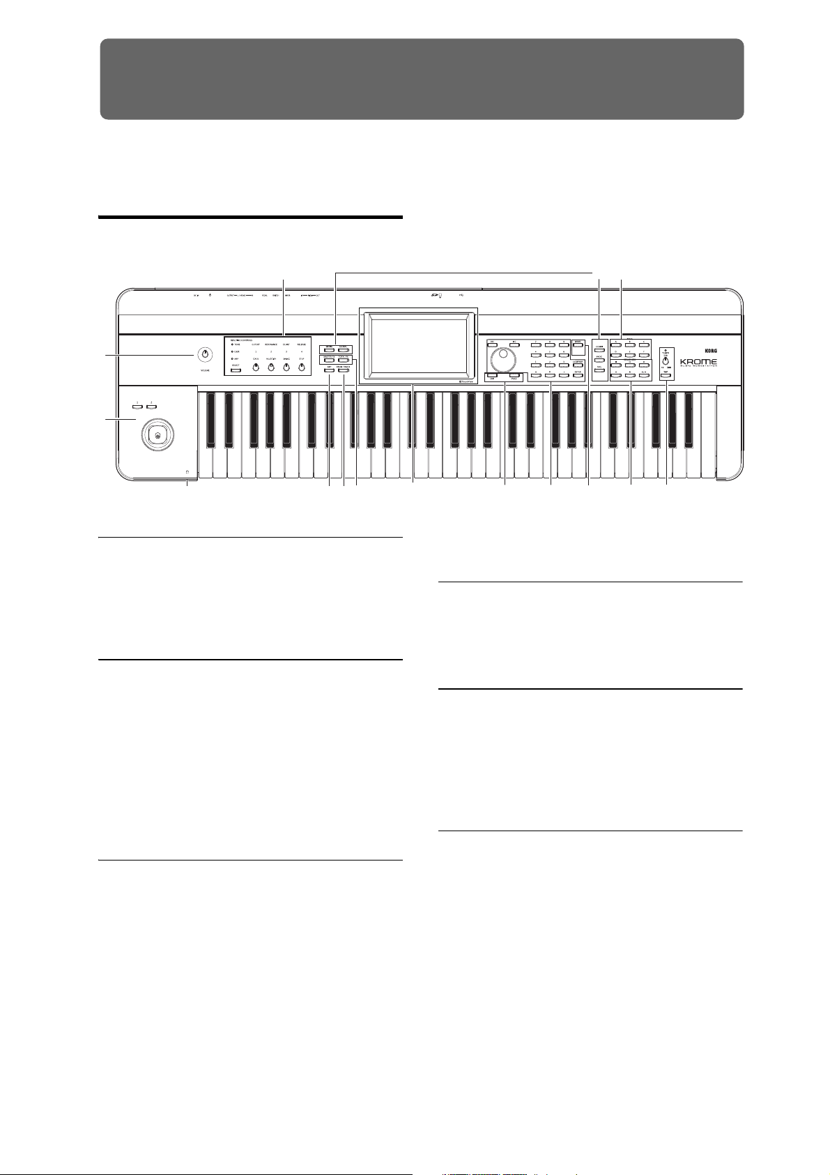
Introduction to the KROME
* The diagram shown is for KROME-61
Front and rear panels
Front panel
3
1
2
15
6
4
5
1. Volume
VOLUME knob
This knob adjusts the volume of the AUDIO OUTPUT
L/MONO, R outputs, as well as the volume of the
headphone jack. (See page 15)
2. SW1, 2 and Joystick
8 9
7
(For details, please see “Using realtime controls to edit
the sound or effects” on page 28.)
11 10
12
13 14
4. Arpeggiator
ARP button
This button turns the arpeggiator on/off. The button
will be lit if the arpeggiator is on. (See page 85)
SW1 and SW2
These buttons are used to control the programs or
effect parameters, or to turn the joystick lock function
on/off. (See page 24)
Joystick
You can control synthesis parameters or effect
parameters by moving the joystick up/down/left/right.
(See page 24)
3. REALTIME CONTROLS
These realtime controllers consist of four knobs and
one button. You can use them to do the following
things.
• Control the sound and effects of programs and
combinations
• Control the arpeggiator
SELECT button, knobs 1–4
Use the SELECT button to select the functions
controlled by knobs 1–4. By using knobs 1–4 you can
control the sound, effects, and arpeggiator.
(For details, please see “Realtime control knobs” on
page 25.)
5. DRUM TRACK
DRUM TRACK button
This button turns the Drum Track function on or off.
This button also indicates the operating state of the
drum track. (Unlit: off, Blinking: waiting for trigger,
Lit: on. See page 97.)
6. Effect buttons
MASTER FX button
TOTAL FX button
These buttons turn the master effect and total effect on/
off. When the button is on (LED lit), the effect settings
of the program, combination, or song will be enabled.
When the button is off (LED unlit), the corresponding
effect will be off.
The on/off status of these buttons is remembered even
when you switch programs, combinations, or songs.
(See page 110)
1
Page 6
Introduction to the KROME
7. Display
Display
The TouchView display features simple touch control
and selection of numerous features and parameters.
(See page 4)
8. Mode
COMBI, PROG, SEQ, GLOBAL, MEDIA buttons
KROME has five different modes, each one is
optimized for a specific set of functions.
Press one of these buttons to enter the corresponding
mode.
For more details, please see “Selecting modes” on
page 9.
9. PROG/COMBI BANK
A, B, C, D, E, F buttons
These buttons select program banks A–F and
combination banks A–D (see page 21, and page 44).
You can also use these buttons to select the bank of
timbre programs in a combination, or the bank of track
programs in a song (see page 46, and page 57).
If you want to select a GM bank, use the numeric keys
(see page 22) or the Bank/Program Select menu (see
page 22).
12. Save (Write)
WRITE button
Use this button to save programs, combinations, global
settings, drum kits, or arpeggio patterns to internal
memory (see page 9).
You’ll also use this button to save songs to media (see
page 75).
When you press this button in the appropriate mode or
page, a Write dialog box will appear. Press the button
once again to save the data.
13. Sequencer
The buttons in this section are used for operations in
Sequencer mode, such as recording and playback (see
page 54). The REC () button is also used to save a
program or combination, or when using the Auto Song
Setup function (see page 59).
PAUSE ( ) button
REW ( ) button
FF ( ) button
LOCATE ( ) button
REC ( ) button
START/STOP ( ) button
14. TEMPO controls
10. VALUE controllers
Use these controllers to edit the parameter that’s
selected in the display.
INC and DEC buttons
VALUE dial
0–9, –, ., and ENTER buttons
Together, these controls specify and confirm the value
of the selected parameter. (See page 10)
COMPARE button
Compares your current edited sound to the sound
before it was edited.
For more details, please see “Compare function” on
page 11.
11. PAGE SELECT, EXIT
PAGE button
When you press this button, a list of the pages within
the selected mode will appear in the display. Press the
button of the desired page. (See page 9)
EXIT button
Press this button to return to the main page of the
current mode. (See page 9)
TEMPO knob
This knob adjusts the tempo of the arpeggiator, drum
track, or internal sequencer.
TEMPO LED
This LED will blink at quarter-note intervals of the
current tempo.
TAP button
By pressing (or tapping) this button on the beat, you
can enter the tempo used by the arpeggiator, drum
track, or internal sequencer (see page 25).
15. Headphone
Headphone jack
Connect your headphones here.
This jack will output the same signal as the AUDIO
OUTPUT L/MONO and R jacks.
The headphone volume is controlled by the VOLUME
knob.
2
Page 7
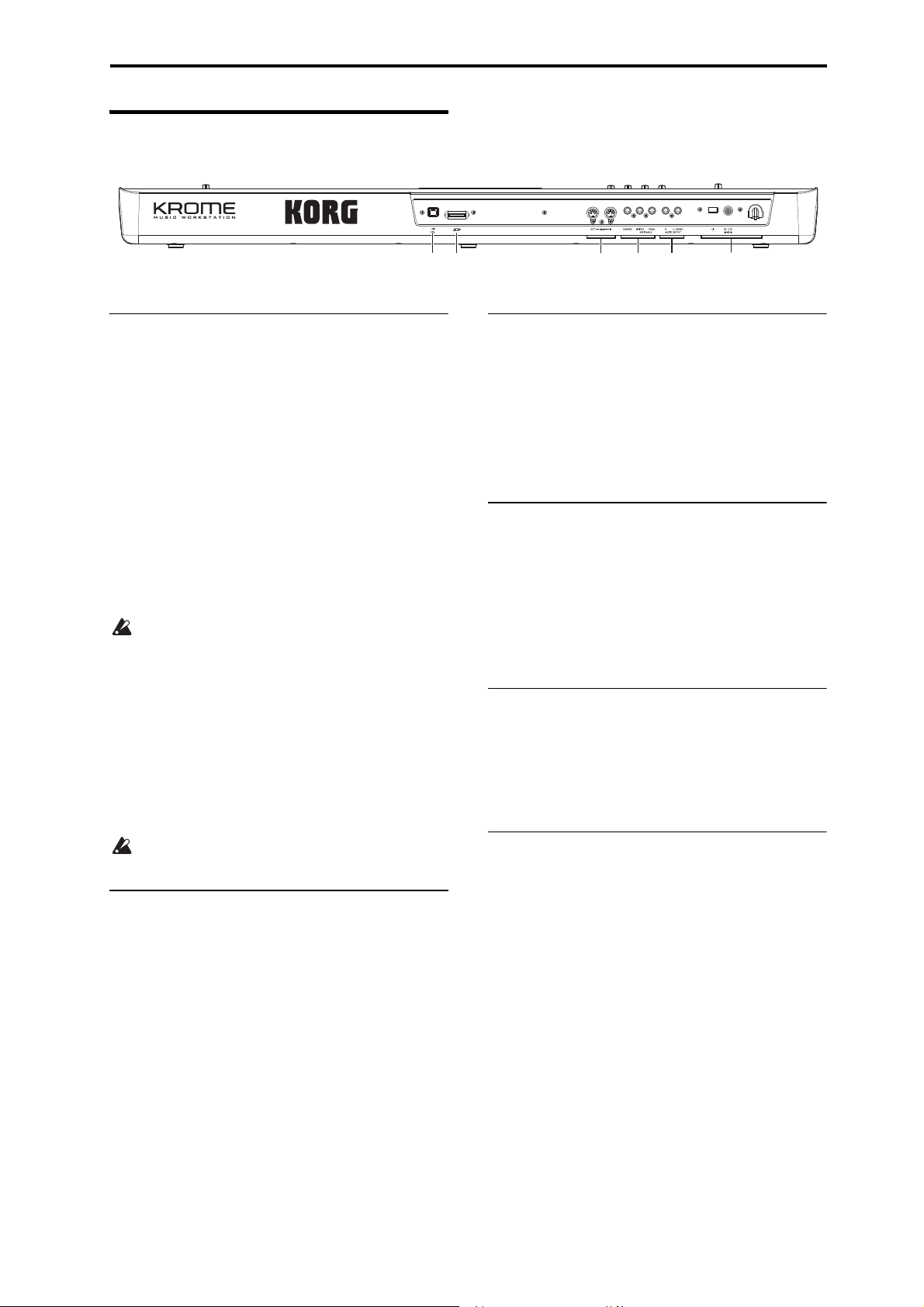
Rear panel
1
2
456
3
Front and rear panels Rear panel
1. Power supply
Be sure to see “Turning the power on” on page 15 and
follow the correct procedure described there.
Note: The KROME has an auto power-off function that
automatically turns off the power when the keyboard
or front panel buttons have not been used for a certain
length of time. With the factory settings, this is set to 4
hours (see “Auto power-off function” on page 16).
Power switch
This switch turns the power on/off. (See page 15)
AC adapter connector
The included AC adapter is connected here.
(See page 15)
Connections must be made with the power turned
off. Please be aware that careless operation may
damage your speaker system or cause
malfunctions.
Cable hook
Use this to secure the cable of the included AC adapter.
After connecting the AC adapter, loop the cable
around the hook located on the KROME’s rear panel so
that the cable won’t get pulled out inadvertently. Leave
enough slack on the plug end so that you can
disconnect it if you want to. (See page 15)
Be careful not to bend the base of the plug any
more than necessary.
3. PEDALS
You can connect a damper pedal, foot switch, and foot
pedal to these jacks. This gives you a broader range of
functions and effects to control. (See page 18)
ASSIGNABLE PEDAL jack
ASSIGNABLE SWITCH jack
DAMPER jack
4. MIDI
MIDI lets you connect the KROME to a computer or
other MIDI devices, for sending and receiving notes,
controller gestures, sound settings, and so on. (See
page 20)
MIDI IN connector
MIDI OUT connector
5. SD
SD card slot
You can insert an SD card here, and use it to save/load
KROME programs, combinations, or song data. (See
page 118)
6. USB
2. AUDIO OUTPUTS
AUDIO OUTPUT L/MONO & R jack
These are the stereo audio outputs. Use the VOLUME
knob to adjust the volume. (See page 17)
USB connector
(for connecting to computer)
You can connect your computer to this connector.
Using a single USB cable, your KROME can send and
receive MIDI information directly to and from a
computer, without requiring a MIDI interface. (See
page 20)
Note: The USB connector of the KROME is only able to
transmit and receive MIDI data.
3
Page 8
Introduction to the KROME
h: Toggle buttons
b: Current page
e: Edit cell
g: Check boxes
i: Popup
button (1)
j: Popup
button (2)
k: Menu command button
a: Mode button l: Stopwatch button
f: Sliders and knobs c: Tabd: Parameters
When selected in Program,
Combination, or
Sequencer mode
When selected in Global or
Media mode
Mode button Page number and name
Tab nam e
Objects in the display
c: Tab
Most pages are divided into two or more tabs.
The KROME uses Korg’s TouchView graphical user
interface.
By pressing or dragging objects shown in the display,
you can select programs or combinations, or edit
parameter values. Here we’ll explain the names and
functions of these objects.
a: Mode button
This indicates the mode that’s currently selected.
When you press this button, the Mode menu will
appear. In the mode menu, press the name of the mode
that you want to move. If you select the currently
selected mode, the Page Select menu for that mode will
appear. Even in another mode, pressing the right side
of the name will display the Page Select menu for each
mode.
To close the menu, press the Close button or the EXIT
button.
If you access this menu from Global or Media mode, it
will include an item named Return. If you press
Return, you will return to the mode where you were
before selecting Global or Media mode.
d: Parameters
The parameters for various settings are shown in the
display.
e: Edit cell
When you touch a parameter in the display, the
parameter or parameter value will usually be
highlighted (displayed in reverse highlighting). This is
called the edit cell, and the highlighted item will be
available for editing.
Use a value controller such as the VALUE dial (see
page 2) to edit the value.
Alternatively, you can edit the value by pressing the
edit cell and using your finger to drag in the direction
of the triangles that appear. (The shading of the
triangles will change in three levels; this function will
become available when the darkest shading is
reached.)
In addition, you can display the edit pad by pressing
twice in succession on the edit cell, or by holding it
down for a time and then releasing it (see page 6).
f: Sliders and knobs
To edit the value of an object shaped like a slider or
knob, press it to move the edit cell. For details on how
to edit the value, please see “e: Edit cell,” above.
The parameter will be active if it is checked, and
inactive if it is unchecked.
Mode menu
b: Current page
This indicates the current page within the selected
mode.
Beginning on the left, this area shows the mode button,
page number: name, and tab name.
4
g: Check boxes
The presence or absence of a check mark in these boxes
will enable/disable parameters or functions. Putting a
check mark in the box will enable the item, and
clearing the check mark will disable it.
h: Toggle buttons
This type of button will change its function or switch
on/off each time it is pressed.
Play/Rec/Mute button (Sequencer mode)
Solo On/Off button (Sequencer mode)
On/Off button for Effect
Page 9
Front and rear panels Objects in the display
Pin
Press here to scroll to left or right.
Press here and slide to left or
right to scroll to the desired
location.
Press here to scroll to the
corresponding location.
Menu command button
Menu
Tex t ed it b utt on
Cancel button OK button
i: Popup button (1)
When this button is pressed, a popup menu will
appear, showing the parameter values that are
available for selection.
To enter the parameter value, press the desired value in
the popup menu.
* Popup menu
Pin
This switches the popup menu
display between locked and
unlocked.
When locked, the pin will be shown
closed, and the popup menu will
remain displayed even after you
press a parameter value. When
unlocked, the pin will be shown
opened, and the popup menu will
close immediately when you press a
parameter value.
j: Popup button (2)
When you press this button, a tabbed menu will
appear.
To close a tabbed menu, press the OK button or Cancel
button.
Scroll bar
Use this when you need to see parameter values that
extend beyond what can be shown in the display at
one time.
* Dialog box
When you select a menu command, you’ll see a screen
containing the settings needed to execute the
command. This is called a dialog box. The dialog box
that appears will depend on the menu command that
you select. Some commands, such as Exclusive Solo,
do not display a dialog box.
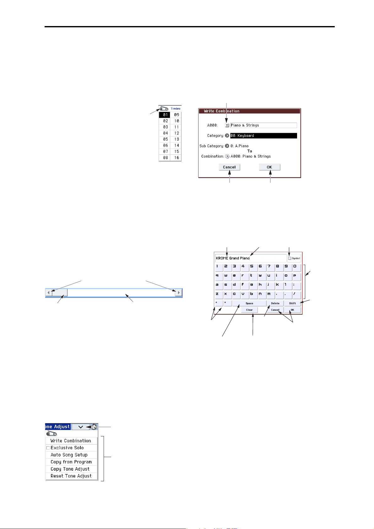
* Text edit button
When you press this button, the text edit dialog box
appears for changing the names of Programs,
Combinations, Songs, etc. For details, please see
“Editing names” on page 117.
Character Set Selects
Text
Cursor
the type of character.
Character
buttons
k: Menu command button
* Menu
When this button is pressed, a list of menu commands
will appear.
The menu commands that appear will differ
depending on the selected page.
You can also select up to ten menu commands by
holding down the ENTER button and pressing a
numeric key 0–9. The menu will close when you press
the display in a location other than the menu, or when
you press the EXIT button.
Shift button
Switches
between
uppercase and
lowercase
Cursor buttons
Move the cursor
to left or right.
Space button
Insert a space at
the cursor location.
Delete button
Deletes the
character to the
left of the cursor.
Clear button
Delete all characters
of the text.
Cancel button, OK button
If you are satised with the text
that you input, press the OK
button. If you wish to discard
your input and exit the text edit
box, press the Cancel button.
characters.
* OK and Cancel buttons
After performing other operations in the dialog box,
you can execute the command by pressing the OK
button. To cancel without executing, press the Cancel
button. (The operation will occur when you press and
release the button.) The dialog box will close.
The EXIT button corresponds to the Cancel button,
Done button, and Exit button.
* Done, Copy, and Insert buttons
There are buttons which perform function when they
are pressed and released, such as Done, Copy, and
Insert (similar to the OK and Cancel buttons explained
under “* Dialog box,” above).
l: Stopwatch button
When you press the button on the upper right of the
display, the time elapsed since power-on will be
displayed. You can use the START/STOP button and
RESET button to measure elapsed time. This is
5
Page 10
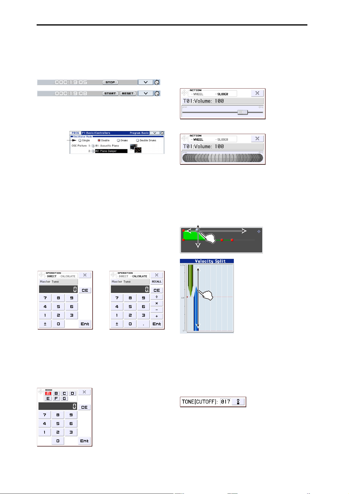
Introduction to the KROME
m: Radio buttons
Numerical input pad Calculator
convenient when you want to check the time during a
live performance or rehearsal, or to determine the
approximate playback time of a song.
• START/STOP: Starts or stops the stopwatch
• RESET: Returns the time to 000:00:00
m: Radio buttons
Press a radio button to select one value from two or
more choices.
* Edit pad
Numerical input pad / calculator
If you press an edit cell, slider, or knob twice in quick
succession, a pad for inputting numbers or using a
calculator will appear. The various buttons have the
following functions.
• OPERATION DIRECT/CALCULATE: Switches
between numerical input pad and calculator.
• CE (clear entry): Clears the currently-input number.
• Ent: Enters the number from the pad into the
parameter, and closes the pad.
• RECALL: Copies the parameter value into the pad.
•Close: Closes the pad.
Value slider / Wheel pad
When you hold down an edit cell, slider, or knob for a
while and then release it, the wheel/value slider will
appear.
To change the value, drag the wheel/slider pad.
SLIDER
WHEEL
Note: If you don’t want the edit pad to appear, clear the
“Value Edit Pop-up” check box in the menu found in
Global P0: Basic Setup– System Preferences (see
page 111).
* EG, Velocity Split
You can change the values of a EG or velocity split
object by dragging in the display.
Note: Some parameters cannot use the calculator
function.
Bank and number select pad
If you press twice in succession on Program Select,
Combination Select, or Timbre Select, the bank and
number select pad will appear.
Bank and number select pad
• BANK: Selects the program or combination bank.
• For other functions, see “Numerical input pad.”
6
* Realtime control popup
When you use a REALTIME CONTROLS knob, a
popup will indicate the function that’s being controlled
and its value. A certain length of time after you stop
using the knob, this popup will close automatically. If
you press the popup while it’s displayed, it will stay
visible, allowing you to enter the value using a value
controller such as the numeric keys.
Note: If you don’t want the realtime control popup to
appear, clear the “REALTIME CONTROL Pop-Up”
check box in the menu located in Global P0: Basic
Setup– System Preferences.
Page 11

Basic Information
About the KROME’s modes
The KROME has numerous functions that let you play
and edit programs or combinations, record and play
back sequence data, and manage media. These
functions are grouped into “modes.” The KROME has
five modes.
Program mode
Programs are the basic sounds of KROME.
In Program mode, you can:
• Select and play Programs.
• Use one arpeggiator in your performance.
• Play back Drum Track patterns while you perform
using a Program.
•Edit Programs
You can use the realtime controls and the Tone
Adjust function to easily edit the program.
You can adjust the parameters and settings of the
oscillators, filters, amps, EGs, LFOs, effects, arpeggiator, drum track, etc.
You can use up to five insert effects, two master
effects, and one total effect.
Plus, you can create drum programs using drum
kits (as created in Global mode).
Basic Information About the KROME’s modes
Sequencer mode
Sequencer mode lets you record, playback, and edit
MIDI tracks. You can:
• Use the sixteen-track MIDI sequencer to record and
play back songs.
Record a single MIDI track at a time, or record as
many as all sixteen tracks simultaneously. You can
also record exclusive messages.
• Use multiple tracks to record and play back
performances generated by two arpeggiators.
• Use one or more tracks to play back the patterns in
the drum track.
• Edit songs.
• Use the KROME as a 16-part multi-timbral sound
module.
• GM/GM2 playback is also supported.
• Use the Tone Adjust function to easily edit the
program of each track.
• Use up to five insert effects, two master effects, and
one total effect.
• Record patterns and assign them to individual
keys, using RPPR (Realtime Pattern Play/
Recording).
• Create a Cue List that will play back multiple songs
in the order that you specify.
• Create user Drum Track patterns.
Combination mode
Combinations are sets of up to 16 programs that can be
played simultaneously, letting you create sounds that
are more complex than a single Program. In
Combination mode, you can:
• Select and play Combinations.
• Use multiple timbres to play arpeggio patterns
generated by two arpeggiators.
• Use one or more timbres to play back the patterns
in the drum track.
• Use the KROME as a 16-track multitimbral tone
generator.
• Edit Combinations
You can use the tone adjust function to easily edit
the program of each timbre.
You can assign Programs to each of the 16 Timbres,
each with separate volume, pan, EQ, and keyboard
and velocity zones; make settings for effects, arpeggiator, drum track.
Plus, you can use up to five insert effects, two master effects, and one total effect.
Global mode
Global mode lets you adjust overall settings for the
entire KROME, and edit drum kits, arpeggio patterns.
In Global mode, you can:
• Adjust settings that affect the entire KROME, such
as master tune and global MIDI channel.
• Create user scales.
• Create drum kits using drumsamples.
• Create user arpeggio patterns.
• Rename program, and combination categories.
• Set the function of the assignable pedals and
assignable buttons.
• Transmit MIDI System Exclusive data dumps.
Media mode
You can save or load data using an SD card. In Media
mode, you can:
• Save and load Programs, Combinations, Songs, and
Global setup data.
• Format SD card, copy and rename files, etc.
• Perform file operations such as copying data to or
from media.
• Export and import sequences to and from SMF
(Standard MIDI Files).
• Use the Data Filer function to save or load MIDI
System Exclusive data.
7
Page 12
Introduction to the KROME
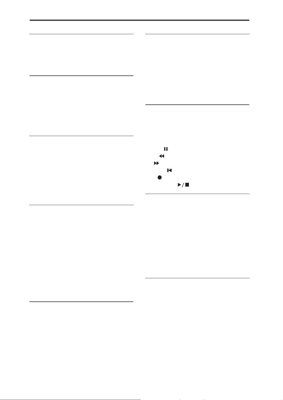
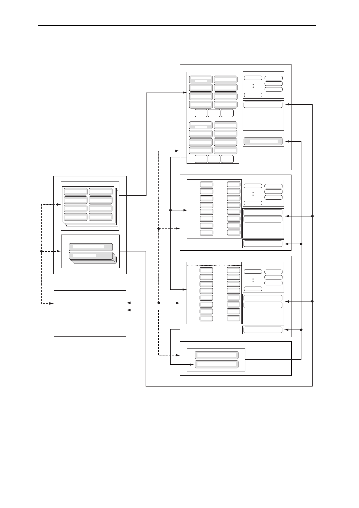
IFX 1
IFX 5
MFX 1
MFX 2
TFX
Insert / Master / Total Eect
TRACK 1
TRACK 8
TRACK 2
TRACK 3
TRACK 4
TRACK 5
TRACK 6
TRACK 7
PROGRAM
PROGRAM
PROGRAM
PROGRAM
PROGRAM
PROGRAM
PROGRAM
PROGRAM
TRACK 9
TRACK 16
TRACK 10
TRACK 11
TRACK 12
TRACK 13
TRACK 14
TRACK 15
PROGRAM
PROGRAM
PROGRAM
PROGRAM
PROGRAM
PROGRAM
PROGRAM
PROGRAM
Arpeggiator B
Arpeggiator A
Drum Track
Drum Track
IFX 1
IFX 5
MFX 1
MFX 2
TFX
Insert / Master / Total Eect
TIMBRE 1
TIMBRE 8
TIMBRE 2
TIMBRE 3
TIMBRE 4
TIMBRE 5
TIMBRE 6
TIMBRE 7
PROGRAM
PROGRAM
PROGRAM
PROGRAM
PROGRAM
PROGRAM
PROGRAM
PROGRAM
TIMBRE 9
TIMBRE 16
TIMBRE 10
TIMBRE 11
TIMBRE 12
TIMBRE 13
TIMBRE 14
TIMBRE 15
PROGRAM
PROGRAM
PROGRAM
PROGRAM
PROGRAM
PROGRAM
PROGRAM
PROGRAM
Arpeggiator
Arpeggiator B
Arpeggiator A
IFX 1
IFX 5
MFX 1
MFX 2
TFX
Insert / Master / Total Eect
MIDI TRACK 1...16
PCG / SNG
PCG
PCG
DrumTrack
DRUMS PROGRAM
ARPEGGIO PATTERN
Preset Drum T rack Pattern
User Drum Track Pattern
Preset Pattern: P0 - 4
User Pattern
OSC 1
PITCH1
FILTER1
AMP1/
DRIVER1
OSC 2
PITCH2
FILTER2
AMP2/
DRIVER2
Multisample 1
Drum Kit
Multisample 5
Multisample 2 Multisample 6
Multisample 3 Multisample 7
Multisample 4 Multisample 8
Multisample 1
Drum Kit
Multisample 5
Multisample 2 Multisample 6
Multisample 3 Multisample 7
Multisample 4 Multisample 8
Key Assign
DRUM KIT
Drumsample 1
Drumsample 5
Drumsample 2
Drumsample 6
Drumsample 3
Drumsample 7
Drumsample 4
Drumsample 8
GLOBAL MODE
PROGRAM
COMBINATION
SEQUENCER
DRUM KIT
MEDIA MODE
MEDIA MODE
ARPEGGIO PATTERN
Relational diagram of the KROME’s modes
8
Page 13
Basic operations
After you’ve turned on the KROME, here’s how to
perform basic operations, such as selecting modes and
pages.
Selecting modes
In order to use a particular function on the KROME,
you must first select the appropriate mode.
• Press one of the front panel mode buttons to enter
the corresponding mode.
COMBI button: Combination mode
PROG button: Program mode
SEQ button: Sequencer mode
GLOBAL button: Global mode
MEDIA button: Media mode
• Alternatively, you can press the Mode button
located in the upper left of the display, and select
the desired mode from a menu (see page 4).
For a summary of each mode, please see “About the
KROME’s modes” on page 7.
Note: The selected mode is shown in the upper left of
the display, and also indicated by the lit status of one of
the above mode buttons.
Note: By pressing the GLOBAL or MEDIA button
twice, you can select the previously-selected mode
(Combination, Program, or Sequencer).
Basic Information Basic operations
2. Press the button for the page that you want to
view.
P0: Play is the page you’ll normally use when
performing on the KROME. (The same is true in
Program mode.) Editing is done in other pages.
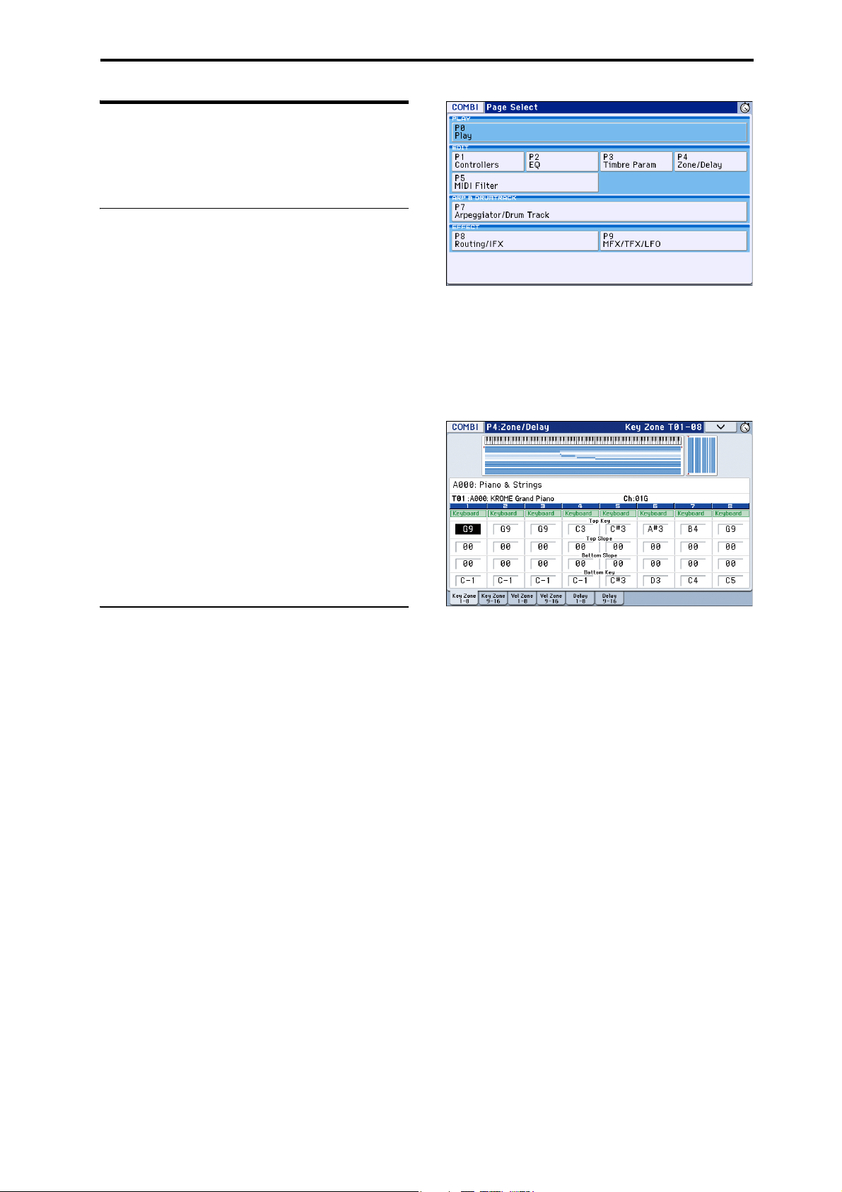
As an example here, try selecting “P4 Zone/Delay.” The
P4: Zone/Delay– Key Z T01–08 page will appear.
Selecting page group and tabs
Each mode has a large number of parameters, which
are grouped into pages. These pages are further
subdivided by tabs; with up to twelve tabs per page.
• Make sure that the desired mode is selected.
For this explanation we’ll use Combination mode as
an example.
Selecting a page group
Moving by selecting a page group
The Page Select screen shows a list of the page groups
within each mode. Select the desired page group from
this list.
1. Press the PAGE button.
Alternatively, you can access the mode menu and press
the mode button, and then press the right side of the
menu (see page 4).
The page select menu will appear.
The page where you were immediately before pressing
the PAGE button is shown in a darker color for your
reference.
Note: The page that appears will be showing the tab
that you most recently selected.
Using the PAGE button plus the numeric keys 0–9
to access different pages
• Hold down the PAGE button and use the numeric
keys 0–9 to specify the page number that you want
to view.
The specified page number will appear. The page
that appears will be showing the tab that you most
recently selected.
Note: In pages consisting of multiple pages such as P5–
1, P5–2, P8–1, and P8–2, the first page (P5–1, or P8–1)
will be selected.
Using the EXIT button to move between pages
If you’re in a page other than page 0 (e.g., Prog P0:
Play) of each mode, pressing this button will take you
to page 0.
This button makes it easy to return to the main page of
the current mode:
• Press it once to go to the previously-selected tab on
the main P0: Play page (Play/REC page in
Sequencer mode).
• Press it again to go to the first tab on the main P0:
Play page (such as the main Program Play page). If
you had previously selected a parameter on this
page, that parameter will be selected.
• Press it a third time to select the main parameter on
the P0: Play page, such as the Program name in
Program mode.
9
Page 14
Introduction to the KROME
When a dialog box is open, this button cancels the
settings made in the dialog box and closes the dialog
box, just like pressing the Cancel button.
If a popup menu or menu is open, pressing EXIT closes
the menu.
Selecting pages
• You can access tabbed pages by pressing the tabs
shown in the bottom line of the display.
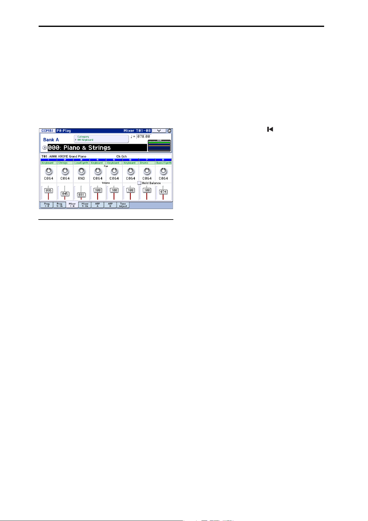
This example shows the Program T01–08 page
through Mixer T01–08 page of Combi P0: Play.
Selecting a parameter and editing the
value
1. Press the parameter that you want to edit.
2. If you select an edit cell, the display will be
highlighted. Edit the value.
• The way that the value will change depends on the
type of parameter or object. (See “Objects in the
display” on page 4.)
The value in the edit cell can be edited by using the
value controllers (VALUE dial, INC/DEC buttons,
numeric keys 0–9, – button, (.) button, ENTER button, etc.).
3. You can use knobs 1–4 to edit parameters that are
assigned to the realtime controls.
Note:
You can use the COMPARE button to compare the
sound you’re editing with the original unedited sound.
INC/DEC buttons
Use these when you wish to make small changes in the
value.
VALUE dial
Use this dial to edit the selected parameter’s value.
This control is convenient when you want to scroll
through a very long list of selections.
Numeric keys 0–9, ENTER button, – button,
(.) button
These buttons are convenient when you know the
exact value that you want to enter. Use the 0–9, –, and
decimal (.) buttons to enter the value, and then press
the ENTER button to confirm the entry.
The – button inverts the sign (+/–) of the parameter
value; the decimal (.) button inserts a decimal, for
entering fractional values.
Note: When selecting “Program Select” (see page 21),
you can select a GM bank by holding down the 0
button and pressing the (.), 1–9, or – buttons.
10
Functions that use the ENTER button in conjunction with another button
ENTER has a few special functions when it is pressed
in combination with other buttons.
By holding down the ENTER button while you press a
numeric key (0–9), you can select up to ten menu
commands from within the current page.
While a dialog box is displayed, the ENTER button
corresponds to the OK button. (The EXIT button
corresponds to the Cancel button.)
In Sequencer mode, you can hold down the ENTER
button and press the LOCATE ( ) button to use the
menu command Set Location.
Other
Specifying a program bank or combination bank
PROG BANK A, B, C, D, E, F/
COMBI BANK A, B, C, D buttons
Use these buttons to change banks when selecting
Programs or Combinations. The LEDs in the buttons
light up to show the current bank.
In Program mode, these buttons select the Program
bank.
In Combination mode, these buttons have two
functions:
• When you’re selecting Combinations, they choose
the Combination bank.
• When you’re assigning a Program to a timbre
within the Combination, they select the Program
bank.
In Sequencer mode, when a track’s Program name is
selected, these buttons change the Program bank.
Using the keyboard to enter a note number or
velocity value
By playing a key while pressing a parameter that
specifies a note number (such as G4 or C#2) or a
velocity value, you can directly enter that note number
or velocity value. (This is not available in menu
command dialog boxes.)
Tempo input
TEMPO knob, TAP button
You can set the tempo by turning the TEMPO knob or
by repeatedly pressing the TAP button.
COMPARE button
You can use this button to return the settings of an
edited program, combination, or song to their original
state. Refer to the following section.
Page 15

Basic Information Basic operations
Menu command button
Menu
Compare function
Program, Combination mode
Use this when you wish to compare the edits you have
made to a program or combination’s sound with the
un-edited original (i.e., the sound that is written into
memory).
When editing a program or combination, press this
button. The LED will light up, and the last-written
settings for that program or combination number will
be recalled. When you press the COMPARE button
once again, the LED will go dark and you will return to
the settings that you were editing.
1. When editing a program or combination, press
this button.
The LED will light up, and the last-written settings for
that program number or combination number will be
recalled.
2. Press the COMPARE button once again.
Note: The LED will go dark and you will return to the
settings that you were editing.
If you edit the settings that are recalled by pressing the
COMPARE button (i.e., the settings that are written
into memory), the LED will go dark, and it will not be
possible to return to the previous edits by pressing the
COMPARE button again.
Sequencer mode
In Sequencer mode, you can use the COMPARE button
to make “before and after” comparisons immediately
after using realtime recording or step recording to
record a song, or after performing an edit on a track.
For example, this can be used effectively when
realtime-recording a MIDI track for a song.
1. Realtime-record a MIDI track. (Take 1)
2. Once again, realtime-record on the same track.
(Take 2)
3. Press the COMPARE button. The LED will light
up, and take 1 will be recalled.
4. Press the COMPARE button once again. The LED
will go dark, and take 2 will be recalled.
5. If at step 3 you once again realtime-record on the
same track (take 3), the Compare function will
now be referencing take 1.
6. If at step 4 you once again realtime-record on the
same track (take 3), the Compare function will be
referencing take 2.
In this way, the Compare function lets you recall the
previous recording or the previous state of event
editing.
Note: If you continue editing when the COMPARE
button is lit, the button will go dark. This now becomes
the musical data that will be selected when the
COMPARE button is dark.
Selecting and executing menu
commands
The menu commands provide commands that are
specific to each page, such as Write (save) or Copy. The
available menu commands will depend on the selected
page.
For example, the menu commands in Program mode
let you write (save) the settings, or let you perform
convenient editing operations such as copying settings
between oscillators or effects, or a Sync function that
lets you edit two EGs together.
1. On the upper right side of the display, press the
button.
The menu command will appear.
2. Select a menu command by touching it with your
finger.
A dialog box for the selected menu command will
appear.
Check-type commands will not display a dialog box;
their status will be switched, and the list will close.
By holding down the ENTER button and pressing a
numeric key 0–9 you can access the dialog box for the
first ten menu commands without going through the
menu.
• If you want to close the list without selecting a
command, press the display somewhere other than
the list, or press the EXIT button.
3. For a parameter in a dialog box, select it by
pressing it with your finger, and use the VALUE
controllers (e.g., VALUE dial or INC/DEC buttons)
to enter its value.
When selecting a program or combination number in a
dialog box, you can also use the BANK button to enter
the bank as an alternative to using the VALUE
controllers.
4. To execute, press the OK button or the ENTER
button.
If you decide not to execute, press the Cancel or the
EXIT button.
The dialog box will close.
v
Global mode
The Compare function that brings back the settings
prior to editing is not available in Global mode.
11
Page 16

Introduction to the KROME
Writing/saving
After editing, you should write or save your changes as
necessary.
For example if you’ve edited a program, your changes
will be lost if you select another program or turn off
the power. The same applies to a combination.
Settings you edit in Global mode and songs will be
remembered as long as the power is on, but your
changes will be lost when you turn off the power,
unless you write these changes into memory.
• You can write or save by pressing the WRITE
button twice.
For more details on the Write operations, see the
following pages.
•Programs p.30
• Combinations p.47
• Effect presets PG p.67
• Global settings (pages 0–4) p.116
•Drum kits p.116
• User arpeggio pattern p.116
• User Drum Track patterns p.103
Preset/user Drum Track patterns are saved in
internal memory even when the power is turned
off. Patterns that you create in Sequencer mode can
be converted into user Drum Track patterns and
saved in internal memory.
• User template songs PG p.164
Preset/user template songs are saved in internal
memory even when the power is turned off. Track
settings and effect settings of a song you create can
be saved in internal memory by using the menu
command Save Template Song.
• For details on writing to internal memory p.115
Refer to the following pages for more information
about saving.
• Saving a song p.75
• Saving to media (Media– Save) p.118
Note: On the KROME, the action of writing to internal
memory is called “Write,” and the action of saving to
an SD card device is called “Save.”
Assigning a name (renaming)
You can edit the name of an edited program,
combination, song, drum kit, or arpeggio pattern.
You can also change the names of the program and
combination categories.
For details, please see “Editing names” on page 117.
Shortcuts
Selecting a GM bank program
• Bank GM: Hold down the 0 numeric key and press
–.
• Banks g(1)–g(9): Hold down the 0 numeric key and
press 1–9.
• Bank g(d): Hold down the numeric key 0 and press
(.).
Moving between pages within a mode
•By holding down the PAGE button and pressing a
numeric key 0–9 you can jump to the
corresponding page.
Access the menu commands in each page (up
to ten items)
• By holding down the ENTER button and pressing a
numeric key 0–9.
Input note number values or velocity values
• While holding down the edit cell in the display,
press a note on the keyboard.
Alternatively, select the edit cell in the display, and
then hold down the ENTER button and press a note
on the keyboard.
Note: You can also use a MIDI note-on message instead
of the keyboard.
Note: While a dialog box is displayed, the ENTER
button will perform the same function as the OK
button. This means that you can’t use this method to
enter a note number or velocity value in a dialog box
that contains an OK button.
Specifying the location in a song
In Sequencer mode, sets the current location as the
Location (equivalent to the Set Location menu
command)
• Hold down the ENTER button and press the
LOCATE ( ) button.
ENTER button
• While a dialog box is displayed, this button
performs the same function as the OK button.
EXIT button
This button makes it easy to return to the main page of
the current mode:
1. Press it once to go to the previously selected tab on
the main P0 page.
2. Press the EXIT button. You will move to the
previously selected parameter of the P0 top page
(Prog: Main, Combi/Seq: Program T01–08).
3. Press the EXIT button. You will move to the
following parameter of the P0 top page.
Prog: Program Select
Combi: Combination Select
Seq: Song Select
12
Page 17

In any page of Program or Combination mode,
pressing EXIT a maximum of two times will
immediately allow you to use the numeric keys or
INC/DEC buttons to select programs or combinations.
In Sequencer mode, pressing EXIT a maximum of three
times will allow you to select a song.
EXIT button (in dialog boxes)
When a dialog box is displayed, this has the same
function as the Cancel, Done, or Exit button.
Initialize the KROME
• With the power off, press the power switch while
holding down the EXIT button and PAGE button.
(While data is being loaded, the display will
indicate “Now writing into internal Memory.”)
The result will be the same as when you’ve
executed Load Preload/Demo Data All.
(See page 125)
Basic Information Basic operations
13
Page 18

Introduction to the KROME
14
Page 19
Setup
Power switch
4: Cable hook
AC adapter
When fastening the
cable to the cable
hook, take care not
to bend this portion
any more than
necessary.
3: Power cord for AC adapter
1: Power
supply jack
2: Plug into AC outlet.
Turning the power on/off
Connecting the AC adapter
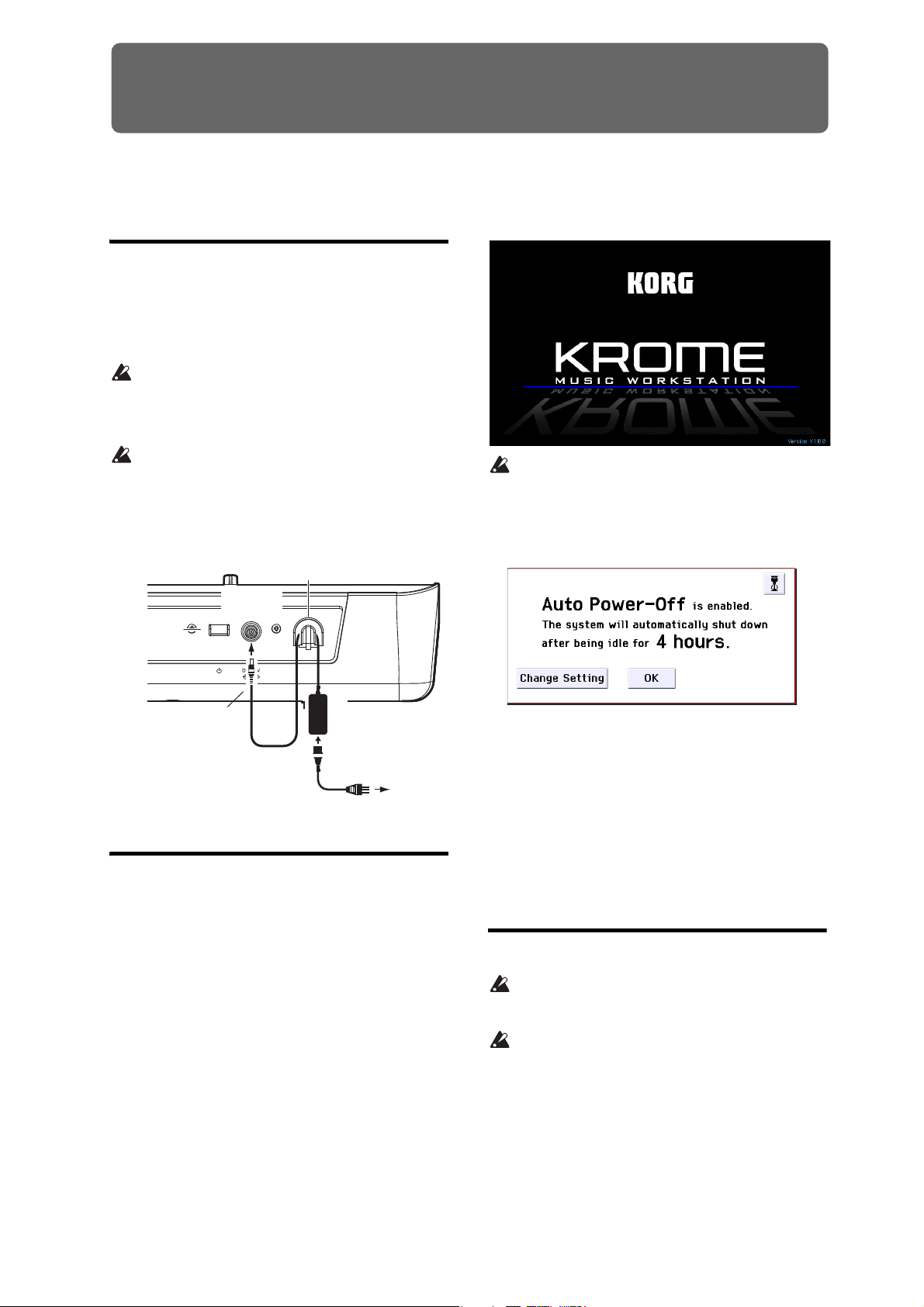
1. Make sure that the KROME is powered-off.
2. Connect the DC plug of the included AC adapter
to the power supply jack on the KROME’s rear
panel.
You must use only the included AC adapter. Using
any other AC adapter might cause malfunctions.
3. Connect the power cord to the AC adapter.
4. Plug the power cord into an AC outlet.
Be sure to use an AC outlet of the correct voltage
for your adapter.
5. Use the KROME’s cable hook to fasten the cable so
that the DC plug does not become accidentally
disconnected.
AC adapter connections
If the auto power-off function is enabled, the time
until auto power-off turns off the power will be
shown when the system starts up. If this dialog
box does not appear, the auto power-off function is
disabled; the power will not turn off automatically
(see “Auto power-off function” on page 16).
Turning the power on
1. Turn the KROME’s VOLUME knob all the way to
the left so that the volume is down.
If external equipment such as powered monitor
speakers are connected, lower their volume as well,
and then turn off their power.
2. Press the power switch on the KROME’s rear
panel to turn the power on.
The display will show the model name and software
version. (The illustration shows the screen that will
appear with the factory settings. This may change
without notice.)
3. Turn on the power of the external equipment that’s
connected to the KROME’s AUDIO OUTPUT L/
MONO and R jacks, such as powered monitor
speakers.
4. Use the KROME’s VOLUME knob and the volume
controls of your external equipment to adjust the
volume to a suitable level.
Note: The page that appears when you turn on the
power will depend on the Power-On Mode setting (see
page 110).
Turning the power off
When you turn off the power, unsaved data will be
lost. Be sure to save any important data such as
edited sounds or global settings (see page 12).
If the KROME’s auto power-off function is
enabled, its power will automatically turn off if
there has been no user input for a certain length of
time. Unsaved data will be lost even if the power is
turned off by the auto power-off function.
1. Turn the KROME’s VOLUME knob all the way to
the left so that the volume is lowered.
2. If external equipment such as powered monitor
speakers are connected, lower their volume and
then turn off their power.
15
Page 20
Setup
3. Press the power switch on the KROME’s rear
panel to turn the power off.
The KROME’s internal data may be damaged if the
power is turned off while data is being written into
internal memory, such as during a Save operation.
Never turn off the power while processing is being
performed.
The following message is displayed while data is
being written into internal memory.
“Now writing into internal memory”
If writing to internal memory could not be
completed successfully, the KROME will
automatically repair the internal memory by
initializing it the next time you turn on the power.
This is not a malfunction. If this occurs, the
following message will appear in the display;
press the OK button.
The internal memory has been corrupted, likely
due to an interruption of power while the system
was writing/saving data. This has been repaired
and the affected Bank has been initialized.
A small amount of electrical power is used even
when the power is off (STANDBY). If you won’t be
using the KROME for an extended period, turn off
the power and unplug the power cord from the
AC outlet.
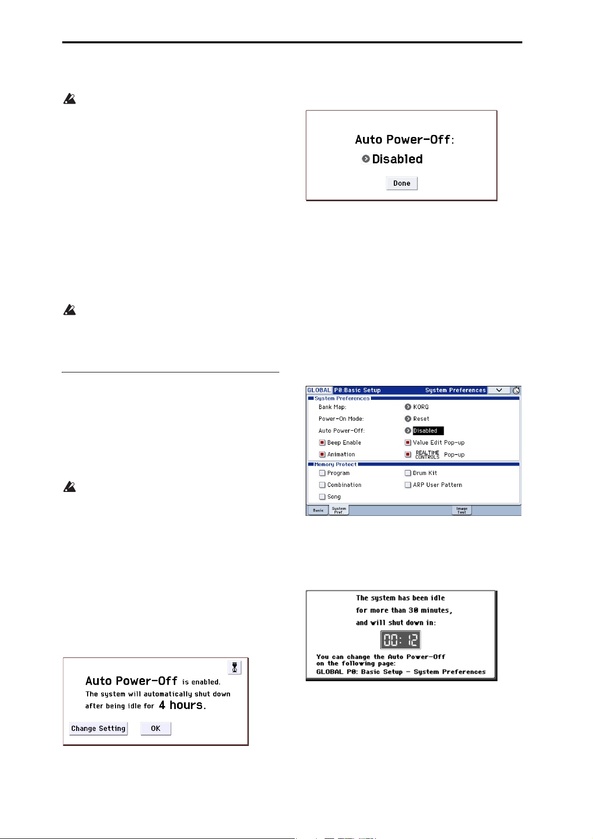
Auto power-off function
1. While this message is displayed, press the Change
Setting button in the dialog box.
The following dialog box will appear.
2. Press the popup button to select the length of time
after which the power will turn off. If you don’t
want the power to turn off automatically, choose
the Disabled setting.
Changing the setting during operation
1. Press the GLOBAL button. (Alternatively, press
the mode button and choose GLOBAL.)
2. Press the EXIT button to access P0: Basic Setup.
3. Press the System Pref. tab to access the System
Preferences page.
4. In “Auto Power-Off,” specify the amount of time
when you want the power to turn off. If you don’t
want the auto power-off function to automatically
turn off the power, choose the Disabled setting.
The KROME supports an auto power-off function that
automatically turns off the power when the keyboard
or front panel buttons
certain length of time.
* Usage of the VOLUME knob is not included.
Note: With the factory settings, the time until
automatic power-off will be approximately four hours.
When the power turns off, the settings you had
been editing will be lost. Make sure that you save
important settings before this occurs.
(*)
have not been used for a
Changing the auto power-off setting
If you want to change the setting so that the power
does not turn off automatically, proceed as follows to
disable the auto power-off function.
Making the change in the dialog box immediately
after start-up
If the auto power-off function is enabled so that the
power will turn off automatically, the dialog box will
appear immediately after start-up, indicating the time
until automatic power-off will occur.
Auto power-off warning message
When the specified length of time has elapsed without
any user input on the KROME, a message will appear,
warning you that the auto power-off function is about
to turn off the power.
16
If you want to continue using the system, press the
keyboard, a button, or the display. The Auto power-off
function will be reset. If the same specified length of
time elapses with no user input, the same message will
appear again.
Page 21
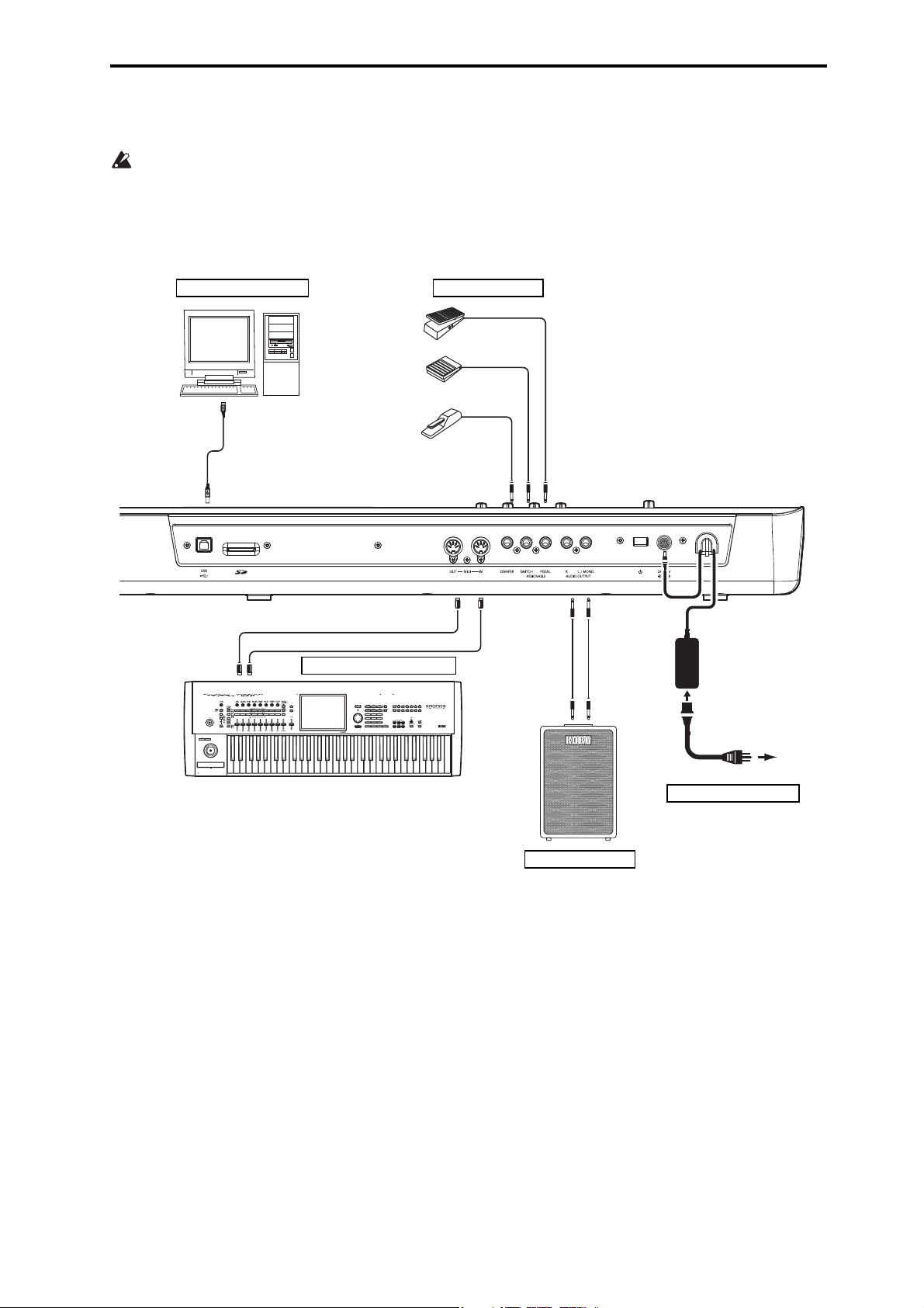
Connections
USB
DAMPER
ASSIGNABLE PEDAL
ASSIGNABLE SWITCH
INPUT
MIDI IN
MIDI IN MIDI OUT
MIDI OUT
R L/MONO
AUDIO OUTPUT
Computer
Analog audio output
Powere d
monitors, etc.
Connections to MIDI equipment
Pedal connections etc.
MIDI cable
AC adapter power
supply connector
Power cab le
(Included)
to an AC outlet
Connecting the AC adapter
Connections to computers
MIDI keyboard
Connections must be made with the power turned
off. Please be aware that careless usage may
damage your speaker system or cause
malfunctions.
Connections Turning the power off
17
Page 22
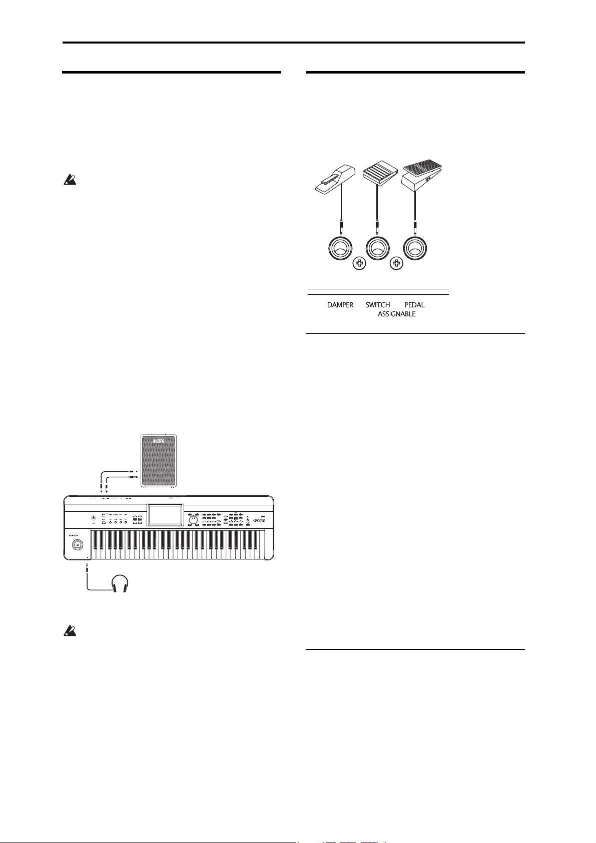
Setup
R
L/MONO
INPUT
PHONES
Powered monitor speakers
Headphones
Audio connections
The KROME does not contain built-in speakers. In
order to hear the sound of your performance, you’ll
need to connect audio equipment such as powered
monitors, a mixer, a stereo set or headphones.
Connecting audio equipment
The KROME’s audio output is designed to
produce a signal level that is higher than consumer
audio equipment such as CD players. For this
reason, performing at high a volume may damage
your speakers or equipment. Please use caution
when adjusting the volume.
1. Minimize the volume of all connected equipment,
and turn off the power.
2. Connect the KROME’s OUTPUT L/MONO and R
jacks to the input jacks of your powered monitor
speakers or mixer.
Note: If you connect only the L/MONO jack, the L and
R sound will be mixed for monaural output. In order to
take full advantage of the KROME’s capabilities, we
recommend that you listen in stereo.
If you’re playing back through your stereo audio
system or a cassette-radio that has external input
connectors, connect the KROME to the jacks that are
marked LINE IN, AUX IN, or external input. (You
might need to obtain the appropriate adapter plug or
conversion cable.)
Connecting headphones
Using headphones at high volume for an extended
time may cause hearing damage. Please avoid
excessively high volume levels.
1. Connect the stereo mini-plug of your headphones
to the KROME’s Headphone jack.
2. Use the VOLUME knob to adjust the headphone
volume.
The KROME’s Headphone jack will output the same
signal as the OUTPUT L/MONO and R jacks.
The output from the OUTPUT jack is not turned off
even if headphones are connected to the Headphone
jack.
Connecting a damper pedal, foot switch, or foot pedal
If you connect an optional damper pedal, foot switch,
or foot pedal to the KROME, you’ll be able to control
the KROME using your feet.
Connecting a damper pedal
When you press the damper pedal, the notes you’ve
pressed will be sustained so that they will continue
even after you take your hands off the keyboard. This
is also called a sustain pedal; it has the same function
as the damper pedal of an acoustic piano.
If the optional Korg DS-1H damper is connected, you’ll
be able to take advantage of the “half-damper” effect,
where the depth that you press the pedal will vary the
damper amount. If any other type of pedal is
connected, it will function as a damper switch.
In Combination or Sequencer mode, you can also select
settings so that the damper will apply to some sounds
but not to other sounds.
1. Connect a Korg DS-1H damper pedal to the
ASSIGNABLE PEDAL/SW1/DAMPER jack.
2. Depending on which assignable jack you have
connected the pedal to, set the controller type
(Type) to Damper, and set the Polarity as
appropriate (see page 202 of the Parameter Guide).
Note: The half-damper sensitivity is adjusted to a
standard value when the KROME is shipped from the
factory. If the half-damper pedal you’re using does not
respond appropriately, please adjust the sensitivity
(see page 217 of the Parameter Guide).
Connecting a foot switch
This lets you use a simple foot switch, such as the Korg
PS-1 or PS-3, as an assignable controller. The foot
switch can perform a wide variety of functions, such
as:
• An assignable source for modulating sounds and
effects
• Portamento on/off
• Program select up or down
• Sequencer start/stop or punch in/out
• Tap Tempo
18
Page 23
Connections Connecting a damper pedal, foot switch, or foot pedal
•Arpeggiator on/off
• Switch the Drum Track on/off
• Use various KROME controls (realtime control
knobs, joystick, SW1/SW2, etc.)
This button will always function in the same way
regardless of the Program, Combination, or Song
you’ve selected. You can assign the function in the
Global mode.
Using a foot switch to select Programs
You can select programs by using a foot switch
connected to the ASSIGNABLE SWITCH jack. By
assigning the appropriate function, you can increment
or decrement the program number in steps of one.
This lets you change Programs without using your
hands–great for quick Program changes in live
performance situations.
There are two ways of doing this: by assigning the foot
switch to Program Up/Down, or to Value Inc/Dec. Each
of these is suited to a particular application, as
described below.
• Prog Up/Down: When performing in the normal P0
screen
• VALUE Inc/Dec: When performing while a list such
as the Category/Program Select menu is open
Assigning the foot switch to Program Up/Down
Assigning the foot switch to Program Up or Program
Down lets you directly control Program changes from
the foot switch. For most situations, this is the more
straightforward method.
To s e t t h is up:
1. Connect a foot switch to the rear-panel
ASSIGNABLE SWITCH input.
Use an optional PS-1 pedal switch.
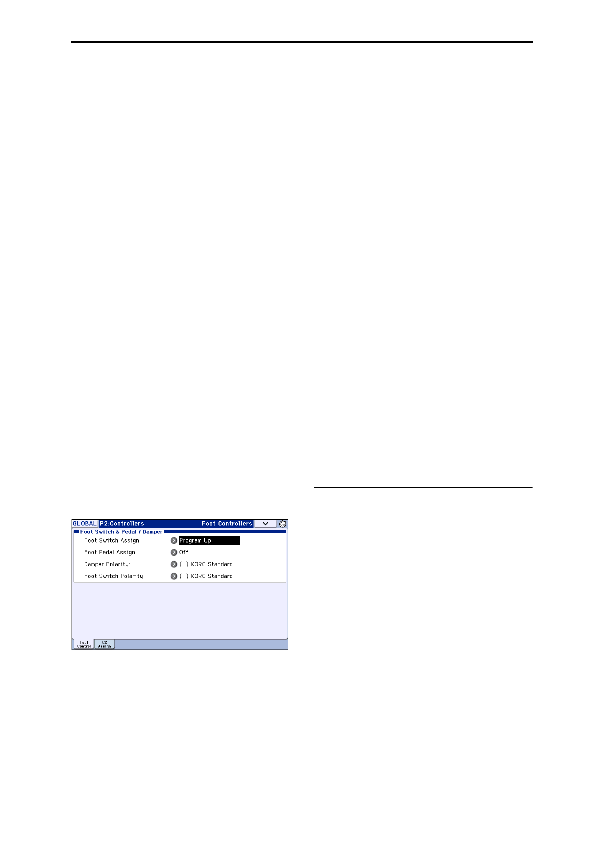
2. Access the Global P2: Controllers– Foot
Controllers page.
Proceed as follows.
Press the GLOBAL button to enter Global mode.
Press the PAGE button to access the GLOBAL Page
Select. Press P2 Controllers, then press the Foot
Control tab in the display.
3. Set “Foot Switch Assign” to either Program Up or
Program Down.
If you choose Program Up, the next program number
up will be selected each time you press the foot switch.
If you choose Program Down, the next program
number down will be selected each time you press the
foot switch.
4. Set the “Foot Switch Polarity” to match the
polarity of the pedal you’ve connected.
If you’ve connected the optional PS-1 or PS-3 pedal,
choose (–) KORG Standard.
Now, the foot switch will step through the Programs,
one by one.
5. If you want to preserve this setting even when the
power is turned off, be sure to Write the data. (See
page 116)
6. Press the PROG button to enter Prog P0: Play, and
press the foot switch to change the Program.
Note:
This setting applies to selecting Combinations, as well.
Note: With the Program Up/Down method, you won’t
be able to select programs while the Bank/Program
Select or Category/Program Select menus are open.
Use the “Assigning the foot switch to Value Inc/Dec”
method described below.
Assigning the foot switch to Value Inc/Dec
This lets you use the Assignable Foot Switch to duplicate
the functions of the front-panel INC or DEC buttons.
This method is convenient if you want to open the
Bank/Program Select menu or the Category/Program
Select menu and switch programs while viewing the
program or combination menu.
1. Follow steps 1–2 under “Assigning the foot switch
to Program Up/Down,” above.
2. At the top of the page, set the Foot Switch Assign
parameter to Value Inc (or Value Dec).
3. Now, the foot switch will act just like you’re
pressing the front-panel INC or DEC buttons.
Note: The foot switch will work like this for the entire
KROME–not just when the Bank/Program select menu
or Category/Program Select menu is open.
Connecting a foot pedal
If you connect an optional EXP-2 foot controller or
XVP-10 expression/volume pedal to the ASSIGNABLE
PEDAL jack, you can use it to apply modulation to
sounds or effects, or to adjust the overall volume.
This pedal will always function in the same way
regardless of the Program, Combination, or Song
you’ve selected. You can assign the function in the
Global mode.
Like the Assignable Foot Switch, described above, the
Foot Pedal can be used for many different functions,
including:
•Master Volume
• Channel Volume, Pan, or Expression
• Assignable sound modulation, as several different
AMS or Dmod sources
• Effects Send level control
• Use various KROME controls (realtime control
knobs, Joystick, SW1/SW2, etc.)
1. Connect an optional XVP-10 or EXP-2 to the
ASSIGNABLE PEDAL jacks.
2. After turning the power on, use Global P2:
Controllers– Foot Controllers page “Foot Pedal
Assign” to assign the function controlled by the
foot pedal. (See page 111, and pages 202, 350 of the
Parameter Guide)
19
Page 24
Setup
MIDI keyboard
KROME
MIDI IN MIDI OUT
MIDI keyboard
MIDI keyboard
MIDI
patch bay
MIDI tone generator
Connecting the KROME to acomputer
USB connection
The KROME provides both MIDI and USB connectors
as standard equipment. By connecting the KROME to
your computer via USB, you can use it as a controller
and MIDI sound module for your DAW software with
single cable convenience; and with out the need for a
MIDI interface.
By using the dedicated editor, you can edit some of the
parameters of the KROME from your computer as
though it were a software plug-in.
Note: The USB connector of the KROME is only able to
transmit and receive MIDI data.
Before you connect the KROME to your computer
via USB, you must install the KORG USB-MIDI
driver on your computer.
Connecting via the MIDI connectors
You can connect the KROME to your computer via
MIDI by using a commercially available MIDI
interface.
Note: For more about MIDI interfaces, refer to the
owner’s manual of the MIDI interface you’re using.
Some USB-MIDI interfaces may be unable to
transmit or receive the KROME’s MIDI exclusive
messages.
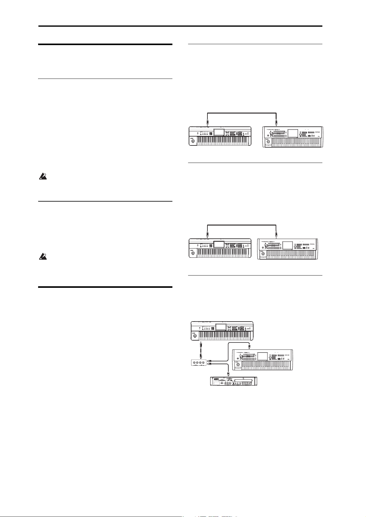
Controlling an external MIDI tone
generator from KROME
If you want to use the KROME’s keyboard, Joystick
and other controllers, sequencer, and arpeggiator to
play or control an external MIDI sound module, use a
MIDI cable to connect the KROME’s MIDI OUT
connector to the MIDI IN connector of your external
MIDI sound module.
MIDI OUT
KROME
MIDI IN
Controlling KROME’s tone generator
from an external MIDI device
When you wish to play or control the KROME’s tone
generator from an external MIDI keyboard or
sequencer etc., use a MIDI cable to connect the MIDI
OUT connector of the external MIDI device to the
MIDI IN connector of KROME.
Connecting MIDI devices
By connecting the KROME’s MIDI connectors to an
external MIDI device you can transfer sound settings
and performance data such as note messages between
your external MIDI device and the KROME.
About MIDI
MIDI stands for Musical Instrument Digital Interface,
and is a world-wide standard for exchanging various
types of musical data between electronic musical
instruments and computers. When MIDI cables are
used to connect two or more MIDI devices,
performance data can be exchanged between the
devices, even if they were made by different
manufacturers.
Controlling two or more external MIDI
tone generators from KROME
You can also use a MIDI patch bay to control multiple
MIDI devices.
KROME
MIDI IN
MIDI OUT
MIDI OUT
MIDI OUT
MIDI IN
MIDI IN
20
Page 25
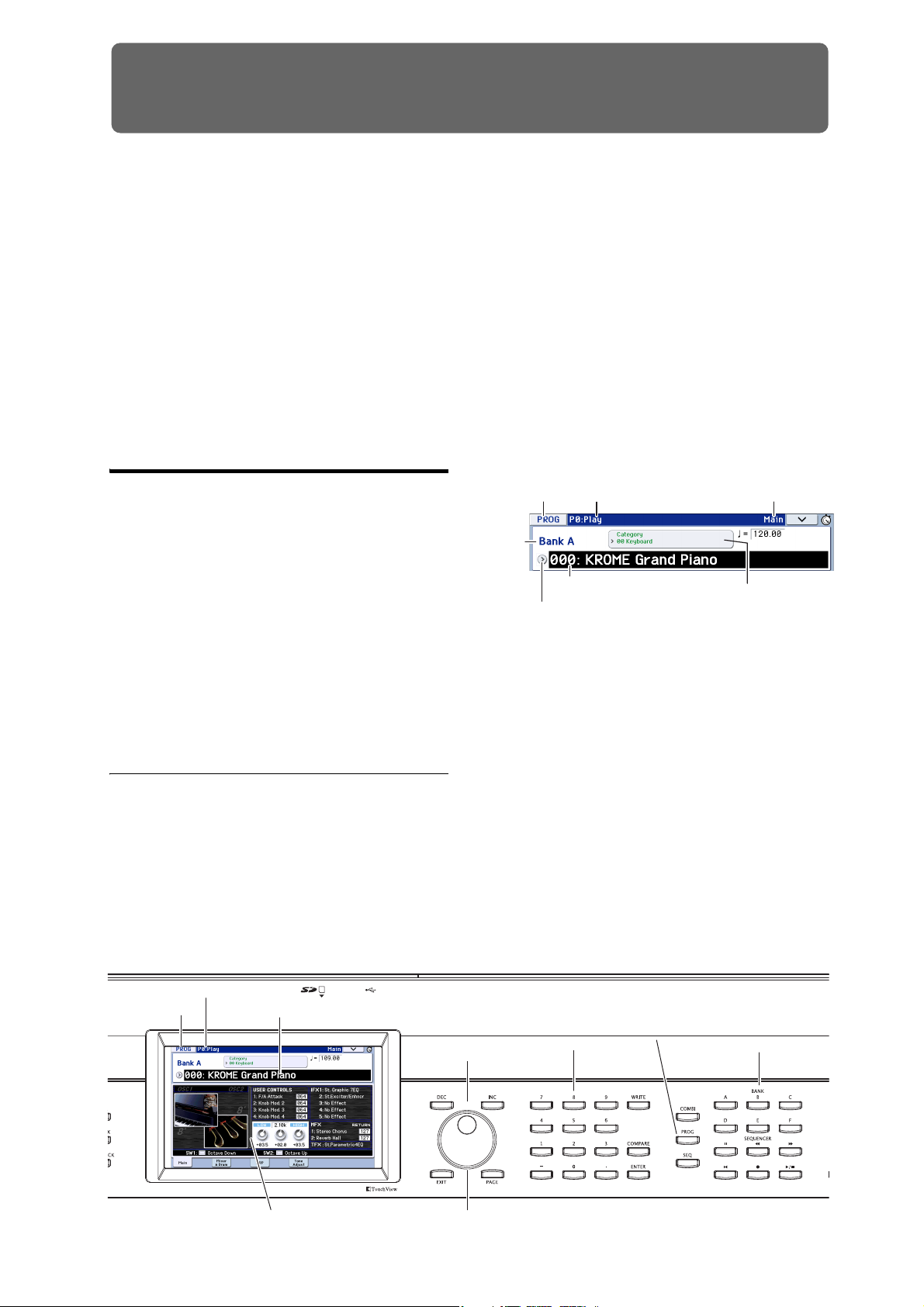
Playing and editing Programs
4: INC/DEC buttons
3: Program Select
2: PROG P0: Play
4: VALUE dial
1: ROG buttons4: Numeric keypads
ENTER button
5: BANK A–F buttons
Velocit y meter
1: Mode name
(button)
Mode button Page number and name Tab name
Program Select
(Program number and name) Category Select popup button
(Category number and name)
Bank
number
Program Select popup button
About the KROME’s Programs
Programs are the basic sounds of the KROME.
You can play them by themselves, layer them together
in Combinations, or play a different Program on each
of the 16 MIDI tracks, either from the internal
sequencer or from external computer-based
sequencers.
This section of the manual takes a quick look at playing
Programs, including tours of the front-panel
controllers and basic editing techniques.
Playing Programs
Selecting Programs
There are several different ways to select Programs.
Each one is convenient in a different way:
• Using “Program Select” and the VALUE
controllers:
• Using the Bank/Program Select menu:
• Using the Category/Program Select menu:
•Find
• Using a foot switch: page 19
• MIDI program change messages let you select
Programs remotely, from either a MIDI sequencer
or an external MIDI controller
For details, please see below.
Selecting a program using “Program
Select” and the VALUE controllers
1. Press the PROG button. (The LED will light up.)
(Refer to the illustration below for the buttons.)
Alternatively, you can use the mode button (see
“Selecting modes” on page 9).
The KROME will enter Program mode.
2. Access the Prog P0: Play– Main page.
This is shown in the top line of the display.
If a different page is shown, press the EXIT button a
few times to return to the Prog P0: Play– Main page.
3. Make sure that “Program Select” is selected.
If it’s not selected, press “Program Select” in the
display or press the EXIT button to highlight the
indication.
4. Select the program you want to play.
You can use the following methods to select a program.
• Use the INC or DEC buttons.
• Turn the VALUE dial.
• Use numeric keys 0–9 to enter the program number,
and press the ENTER button.
5. Press one of the PROG BANK A–F buttons to
select a bank.
When you select a different Bank, the button’s LED will
light up, and the selected bank will appear on the left
side of the display.
21
Page 26
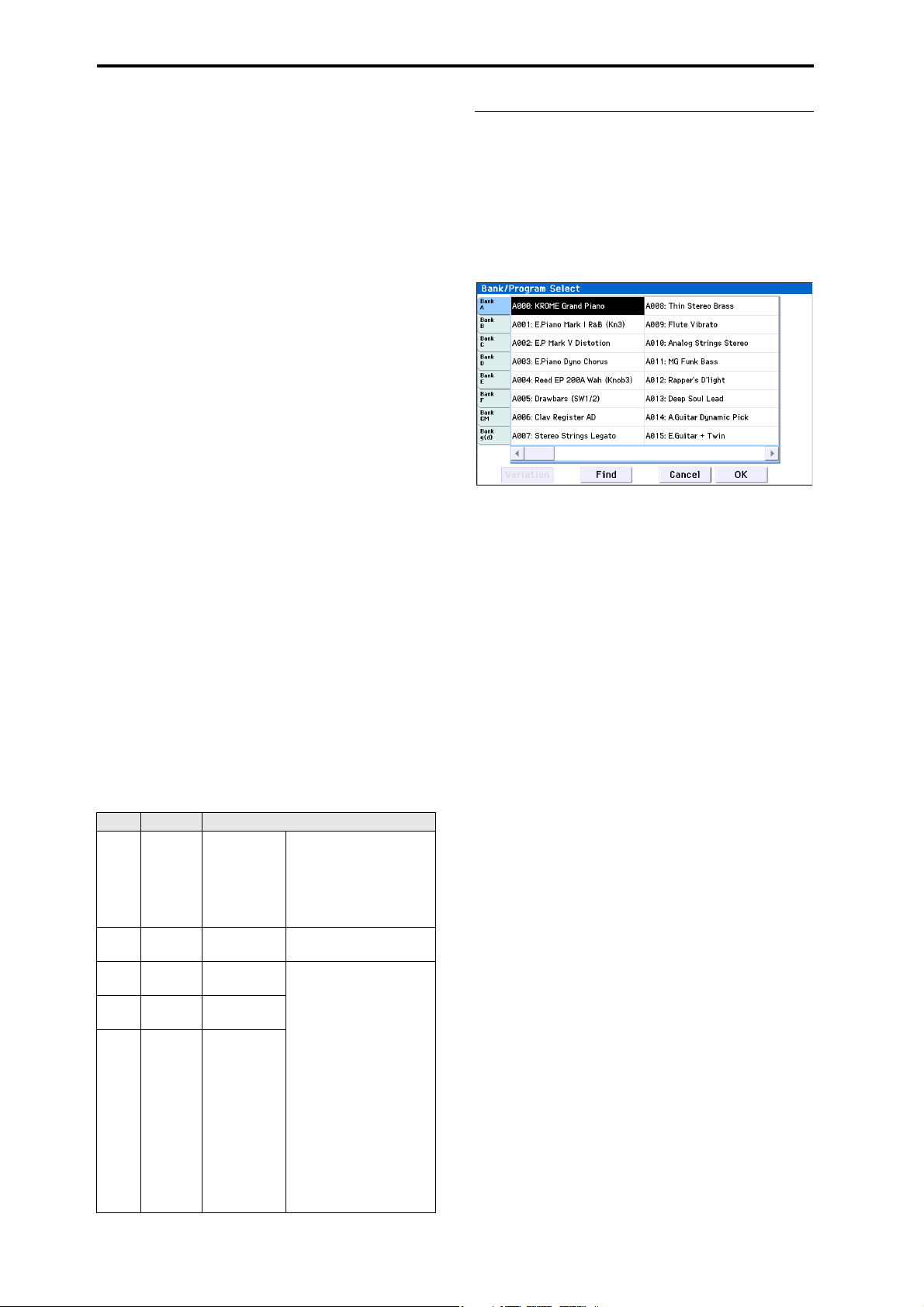
Playing and editing Programs
For example, to select bank B, press the PROG BANK B
button. The B button will light up, and the name Bank
B will appear on the left side of the display.
• To select a GM bank, you’ll use the numeric keys.
GM: Hold down 0 and press –.
g(1)–g(9): Hold down 0 and press the desired number 1–9. For banks that do not have variation
sounds, the basic GM sounds will be recalled. (An
“*” will be appended to the beginning of the program name.)
g(d): Hold down 0 and press (.).
Auditioning the sound
Play the keyboard to audition the program you’ve
selected.
The velocity meter shows the note-on velocity.
• This shows the velocity value of note-on events for
the global MIDI channel, such as the keyboard,
MIDI IN, and arpeggiator. (If multiple note-on
events are received simultaneously, the highest
velocity value is shown.)
• Since this shows the note-on velocity values, it will
not be affected by the settings of the volume knob
or by changes in the audio signal level.
Overview: Program Banks
As program banks, the KROME provides the six banks
A–F and the GM banks (GM–g(d)). With the factory
settings, the KROME has 640 preload programs in
banks A–E. Bank F contains only initialized programs.
Programs you’ve created should be stored in this bank.
With the exception of the GM–g(d) banks, you are free
to save by overwriting these program memory areas.
You can also save these programs on an SD card.
Programs are organized into six banks as shown in the
following table.
Program bank contents
Bank Prog. No. Explanation
With the factory settings,
these banks contain a wide
A…E 000…127
F 000…127
GM 001…128
g(1)…
001…128
g(9)
g(d) 001…128
Fac tor y
Programs.
Initialized
Programs.
GM2 main
programs.
GM2 variation
programs.
GM2 drum
programs.
variety of preloaded
programs that use the
internal multisamples,
effects, and arpeggiator.
Use these to create a
program from scratch.
These banks contain 256
GM programs and nine GM
drum programs that are
compatible with the GM2
sound map. The programs
of these banks are readonly.
Bank GM contains the GM
programs. GM lets you
select 128 programs
numbered from 001–128,
and g(1)–g(d) lets you
select nine drum
programs.
You can’t write (save) data
to these banks.
Selecting by Bank/Program Select
menu
You can select Programs from a menu organized by
Program bank.
1. Press the Program Select popup button.
The Bank/Program Select menu appears.
Bank/Program Select menu
In this illustration, Bank A is selected. The menu
displays the Programs contained in that bank.
2. Press the tabs on the left side of the display to
select banks.
3. Press one of the program names in the center area
to select a program.
The selected program will be highlighted, and the
program will change.
Alternatively, you can use the INC/DEC buttons to
switch programs.
Play the keyboard to hear the program you selected.
4. If you selected Bank GM, the Variation button is
shown.
By repeatedly pressing this Variation button, you can
successively step through the banks, allowing you to
recall a GM2 sound set (see “To select a GM bank” on
page 22).
5. When you are satisfied with the selected Program,
press the OK button to close the menu.
If instead you press the Cancel button, the selection
you made here will be discarded, and you will return
to the program that had been selected before you
opened the menu.
22
Page 27
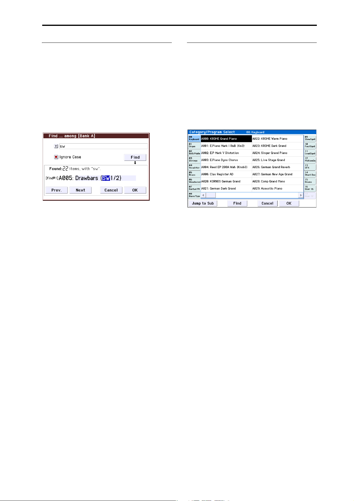
Playing Programs Selecting Programs
Find
Here’s how to search for a program by a portion of its
name.
1. Access the Bank/Program Select menu or the
Category/Program Select menu, etc.
2. Press a tab to select the bank or category that you
want to search.
Note: The programs included in the selected tab will be
the subject of the search.
3. On the lower left side, press the Find button to
access the dialog box.
4. Press the “T” button to access the text dialog box.
Enter the alphanumeric characters that you want to
find, and press the OK button. For example if you want
to find programs that take effective advantage of SW1
or SW2, enter “sw”.
5. If you select the “Ignore Case” check box,
uppercase and lowercase characters will not be
distinguished in the search.
6. Press the Find button to begin searching.
Search results are shown in “Found.”
If one or more items are found, the number of items
and the first found program will be displayed.
Press the Prev. button or Next button to find the
previous or next program. This will cycle through the
found items within the tab.
You can play the keyboard to audition the program
that was found.
If no items are found, the display will indicate
“nothing.”
7. If you are satisfied with the selected program,
press the OK button to close the menu.
The selected program will be selected in the menu you
selected in step 1. If you are satisfied with the selected
program, press the OK button to close the menu.
If you want to search for a different program, or if no
items were found, press the Cancel button.
8. Press the tab that you want to select next, and
search as described in steps 3–7.
If you press the Cancel button, this selection will be
discarded, and you will return to the program that had
been selected prior to opening the menu.
Selecting by Category/Program Select
menu
You can select Programs from within a category, such
as keyboard, organ, bass, and drums.
When shipped from the factory, the preloaded
Programs are organized into 16 categories, each with
several sub-categories.
1. Press the Category Select popup button.
The Category/Program Select menu appears.
Category/Program Select menu
In the illustration above, the Keyboard category is
selected. The menu in the center column area shows
the Programs which belong to that category.
2. Press the tabs to the left and right of the display to
select a different category.
The name of the selected category will be displayed in
full in the top right-hand corner.
3. Press one of the program names in the center area
to select a program.
The selected program will be highlighted, and the
program will change.
Alternatively, you can use the INC/DEC buttons to
switch programs. Touch the scroll ribbon at the bottom
of the screen to see all of the Programs in that category.
Play the keyboard to hear the program you selected.
4. If you want to select from a sub-category, press the
Jump to Sub button to access the Sub Category/
Prog Select menu.
Press the left tabs to select a sub-category.
Note: You can’t select tabs for a sub-category that has
no associated programs.
Select a program as described in step 3 above.
Press the OK button to confirm your selection, or press
the Cancel button to discard it. You will return to the
main category.
5. When you are satisfied with the selected program,
press the OK button to close the menu.
If instead you press the Cancel button, your selection
will be discarded, and you will return to the program
that had been selected when you opened the popup
menu.
23
Page 28
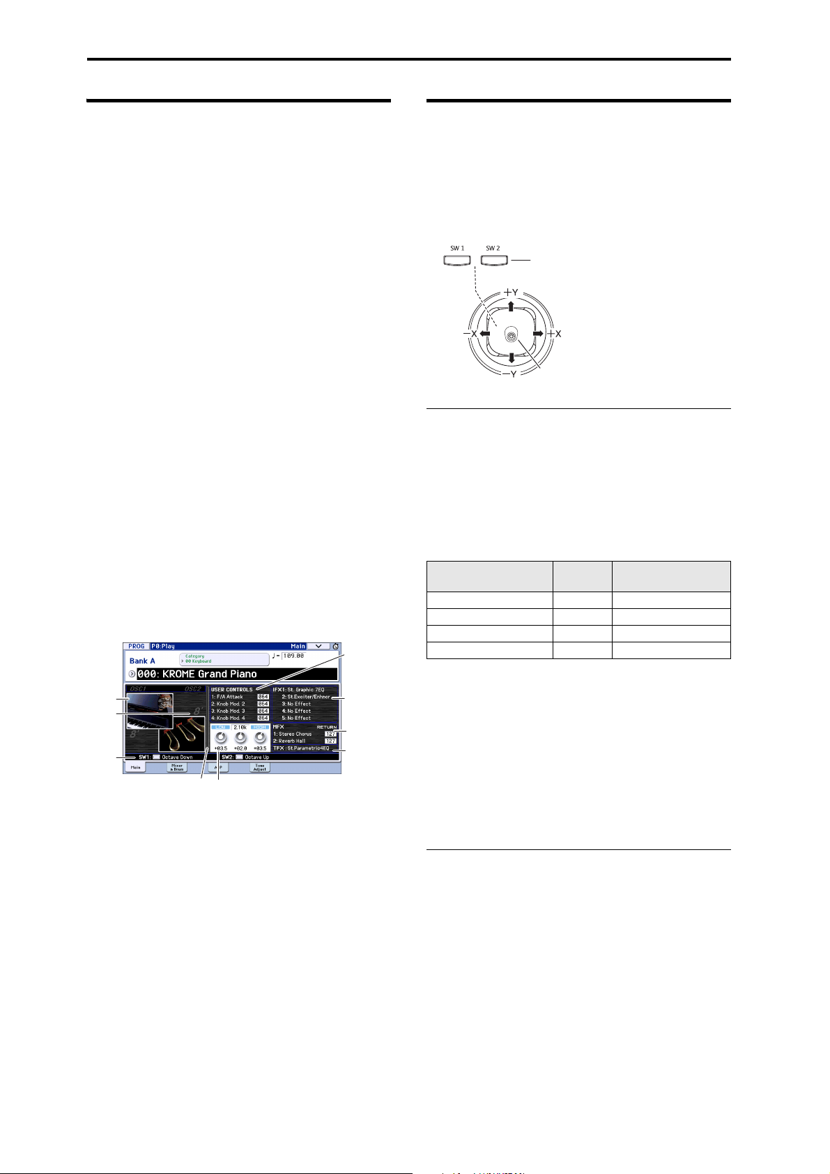
Playing and editing Programs
(Lock
function)
Joystick
Program information
In the Prog P0: Play– Main page you can view the
following information about the selected program.
OSC Picture: This is a graphic that represents the
program’s oscillator.
OSC Oct: For a double oscillator or double drums, this
indicates “Oct” (the basic pitch of the oscillator).
SW1, SW2: This indicates the function that’s assigned
to the SW1/SW2 buttons, and the on/off state of the
buttons.
Realtime Controls – TONE CONTROLS/USER
CONTROLS/ARP CONTROLS:
This shows information about the functions of the
REALTIME CONTROLS knob that’s currently selected.
Use the SELECT button to choose the functions that
will be controlled by the knobs. For more information
about these functions, please see page 28.
EQ (Low, Mid[Hz], Mid, High): This shows the 3-band
EQ settings. You can use the value controllers to edit
the values.
Effect Controls– IFX, MFX, TFX:
This shows the effects that are assigned. The KROME
provides insert effects 1–5, master effects 1 and 2, and a
total effect. For the master effects, you can edit the
return levels.
Velocity Meter:
This meter shows the note-on velocity value.
The meter shows the note-on velocity of the keyboard,
MIDI IN, and arpeggiator etc. (If multiple note-on
messages are received simultaneously, the highest
velocity value is shown.)
Realtime Controls
- Tone Controls
- User Controls
OSC
Picture
OSC Oct
SW1,
SW2
Velocity Meter
EQ
- Arp Controls
Eect Infomation
IFX 1-5
MFX 1, 2,
Send level
(On/O)
TFX (On/O)
Using Controllers
In addition to using the keyboard, the KROME lets you
control the sound by using the joystick, SW1 and SW2
buttons, knobs 1–4, damper pedal, and foot switch or
foot pedal.
These controls let you modify the tone, pitch, volume,
effects, etc. in realtime as you play.
[SW1], [SW2]
Joystick
The joystick moves in four directions: left, right, up
(away from yourself), and down (towards yourself).
Each of the four directions can be used to control a
different function, such as modulating Program or
effects parameters. These assignments can be different
for every Program, but generally, they do the following:
Standard Joystick functions
Move the joystick…
Left JS–X Pitch bend down
Right JS+X Pitch bend up
Up (away from yourself) JS+Y Vibrato
Down (towards yourself) JS–Y Filter LFO (wah)
For details, please see page 82.
Joystick Lock
This function lets you maintain the effect that had been
applied prior to releasing your hand from the joystick.
You can use the SW1/SW2 buttons or a foot switch
connected to the KROME to lock the current position
so that the effect will continue even after the joystick
returns to the center position. For details, please see
“Locking the Joystick” on page 25.
Controller
Name
Normally controls…
SW1, SW2
You can use these buttons to control program
parameters via AMS (Alternate Modulation), or effect
parameters via Dmod (Dynamic Modulation).
They can also transpose the keyboard by octaves, turn
portamento on/off, or to lock the position joystick.
Each button can work as either a Tog g le or Momentary
button. In Toggle mode, the assigned function is
switched between on and off each time the button is
pressed. In Momentary mode, the assigned function is
active on only as long as you hold down the button.
In Program mode, you can check the assignments of
SW1 and SW2 on the Prog P0: Play– Main page.
For details, please see “Program information” on
page 24.
24
Page 29
Playing Programs Using Controllers
When you write a Program or Combination, the on/off
status of the SW1 and SW2 buttons is saved.
For details, please see page 82.
Locking the Joystick
1. Using the standard factory sounds, select Program
C027: Semi Distortion Guitar.
To select a program, make sure that you are in Program
mode, and press the PROG BANK C button, numeric
key 2, 7, and then the ENTER button.
2. While holding down a key, move the joystick in
the –Y direction (toward yourself).
The tremolo effect will deepen.
3. While keeping the joystick in the –Y direction
(toward yourself), press the SW2 button. (The SW2
button LED will light up.)
When you press the button, its LED will light up, and
the modulation effect at this point will be maintained.
4. Release the joystick, and play the keyboard.
The modulation will stay the same as it was when SW2
was pressed. Even if you move the joystick toward
yourself, the sound will not change.
5. Press the SW2 button once again to release the
Lock function.
Keyboard
The KROME’s keyboard provides the following two
types of control.
1. Press the SELECT button to select the realtime
control function between TONE, USER, or ARP.
TONE, USER: Use the knobs to modify the sound or
effects (see page 28).
ARP: Use the knobs to control the arpeggiator (see
page 86).
You can freely switch between these functions without
losing your current edits.
2. Use knobs 1–4 to control the selected functions.
When you turn one of these knobs, that knob’s function
and value will appear in a popup.
(You can prevent this popup from appearing. See
page 111.)
There will be a slight amount of play when turning
the knob near its minimum or maximum positions.
TEMPO knob and TAP button
This adjusts the tempo for the KROME as a whole,
including:
• Arpeggiator
• Drum Track
• Songs in Sequencer mode
• Tempo-synced LFOs
• Tempo-synced (“BPM”) delay effects
TEMPO LED
The LED will blink at quarter-note intervals of the
current tempo.
Velocity
Velocity is a measure of how hard you play a note on
the keyboard. This can be used to modulate many
different aspects of the sound, such as volume,
brightness, or the character of the attack.
Note Number
Sounds can be programmed to change in character
based on the note being played.
As you play higher or lower on the keyboard, the note
number can modulate the timbre - such as becoming
brighter as you play higher notes. Envelopes may also
become faster or slower; the volume may change; and
so on.
Realtime control knobs
The realtime controls consist of four knobs and the
SELECT button. These controls function as follows.
• You can apply modulation to sounds or edit them.
• You can control the arpeggiator.
TEMPO knob
This knob adjusts the tempo. It’s a convenient way to
make continuous adjustments.
Note: If the Global P1: MIDI– MIDI Basic page MIDI
Clock parameter is set to External MIDI, External USB,
or if it is set to Auto and a clock is currently being
received via MIDI, then neither the TEMPO knob nor
the TAP button will have any effect.
TAP button
You can set the tempo of the Arpeggiator or Drum
Track function in Program, Combination, and
Sequencer modes by lightly pressing or tapping the
TAP button several times on the beat. In Sequencer
mode, you can control the song tempo in this way.
To enter the tempo, use your finger to gently tap the
TAP button. The tempo will be entered when you press
the button twice, but you should tap several times in
order to increase the precision. The average of the last
sixteen taps will be specified as the tempo.
During playback, lightly press the TAP button several
times at the desired tempo. The tempo will follow your
tapping in realtime. This is a convenient way to match
the tempo in realtime to the beat of a different source.
You can use tap tempo control whenever the
TEMPO knob can be used. For example in
Sequencer mode, tap tempo control will not be
available if you are playing a song where the
Tempo M od e setting is set to Auto. (See page 110
of the Parameter Guide)
Note: You can also use a foot switch connected to the
ASSIGNABLE FOOT SWITCH jack to control the tap
25
Page 30

Playing and editing Programs
tempo function (see page 18, and pages 202, 349 of the
Parameter Guide).
Performing with the
Damper pedal / Foot switch / Foot
pedal
For details on using the damper pedal, foot switch, or
pedal to control the sound, please see “Connecting a
damper pedal, foot switch, or foot pedal” on page 18.
arpeggiator or drum track
Based on note data that it receives from the keyboard
or from the MIDI IN connector, the arpeggiator can
generate a wide range of phrases and patterns
including arpeggios, guitar or keyboard backing riffs,
bass phrases, or drum patterns. By setting SELECT to
ARP and using the knobs, you can vary the duration
and strength of the arpeggiated notes.
For more about the arpeggiator, please see page 85.
The drum track uses a rich variety of drum patterns to
play the KROME’s high-quality drum programs. You
can select any program and play along with the drum
patterns.
Of course you can also synchronize the arpeggiator
and the drum track patterns and use them together.
For more about the drum track, please see page 97.
26
Page 31
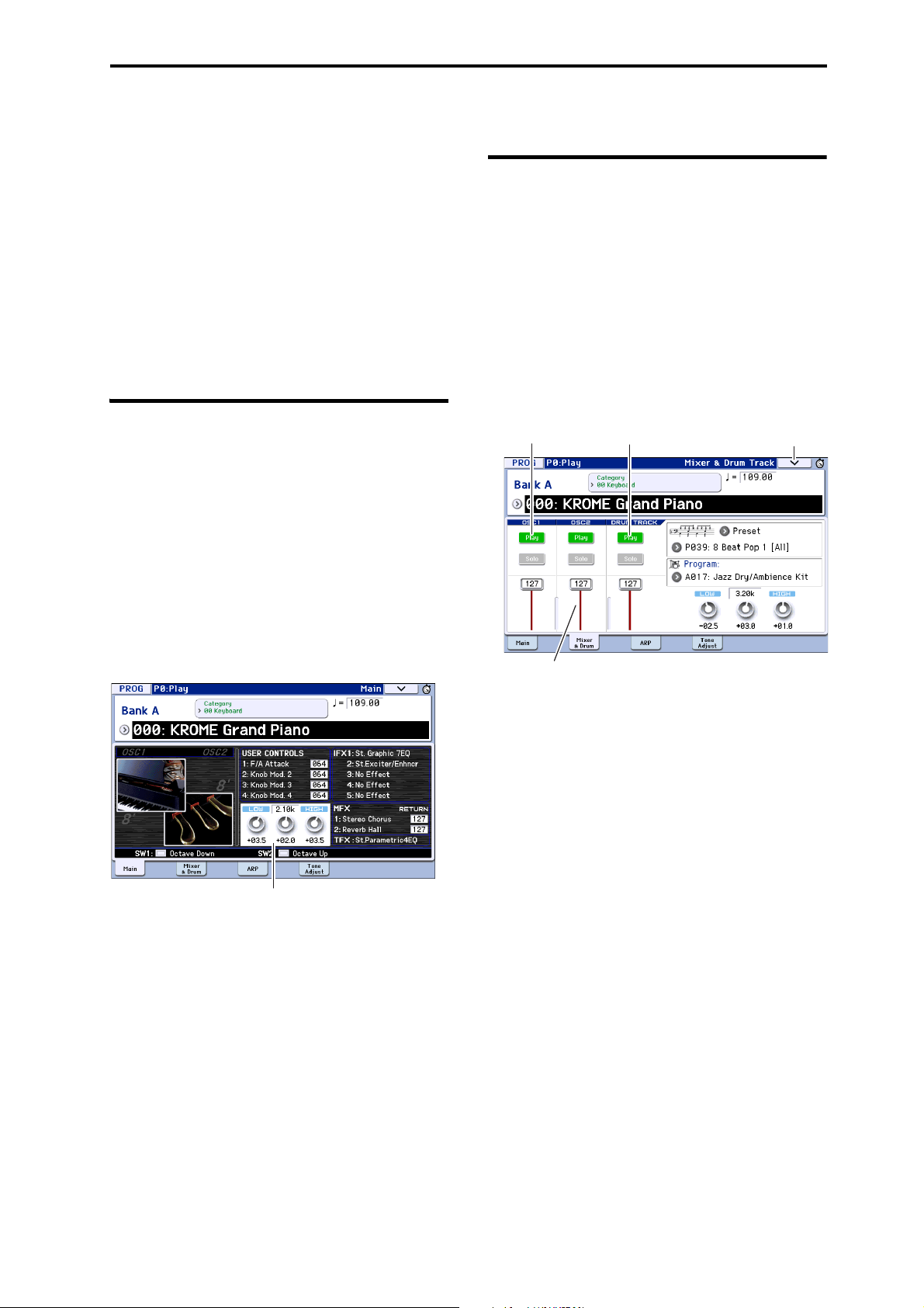
Easy Program editing
EQ
OSC Play/Mute Drum Track Play/Mute
Volu me
Menu
The fastest way to create the sound you need is to start
from a preload program that’s close to what you have
in mind, and edit that program.
Simple editing can be done within the various pages of
P0: Play where you perform. You can adjust the EQ
and volume level, and in the Tone Adjust page you can
use the sliders and buttons to perform various useful
edits. You can also use the front panel realtime controls
to intuitively adjust the cutoff, resonance, and release
time.
If you want to do detailed editing, use the editing
pages P1 and following.
Adjusting the EQ
You can adjust a mid-sweepable three-band EQ in the
Prog P0: Play– Main page.
Note: This EQ will affect both oscillator 1 and oscillator
2.
1. Access the Prog P0: Play– Main page.
2. On the display, select the EQ gain knob or the
center frequency of the Mid sweep EQ that you
want to edit.
3. Use the VALUE controllers (e.g., VALUE dial) to
edit the value.
You can also edit the value by dragging left or right on
a knob or edit cell in the display.
Easy Program editing Adjusting the EQ
Adjusting the volume balance
A program’s sound consists of up to two “oscillators”
which are played mainly from the keyboard, and one
“drum track” which automatically plays the rhythm
section.
The volumes of the oscillators and the drum track can
be adjusted in the Prog P0: Play- Mixer & Drum Track
page.
Note: There’s also a “mute function” which
individually silences these, and a “solo function”
which mutes all sounds other than the specified one.
1. Access the Prog P0: Play– Mixer & Drum Track
page.
2. Select a slider in the display, and use the VALUE
dial etc. to adjust the volume of oscillators 1 and 2
and the drum track.
For oscillators that use two drum kits, you can use the
OSC1 and OSC2 sliders to adjust the direct sound of
the close-miced drum kit and the ambient sound of the
drum kit captured with more space.
Note: With single-oscillator programs, you won’t be
able to control oscillator 2.
3. You can press the Play/Mute button in the display
to toggle the Play/Mute status of oscillators 1 and 2
and the drum track.
4. You can press the Solo button in the display to
toggle the Solo On/Off status of oscillators 1 and 2
and the drum track.
The function of the Solo button will switch each time
you select “Exclusive Solo” in the menu (see page 64 of
the Parameter Guide).
27
Page 32

Playing and editing Programs
Level
Frequency
HighLow
Cut off
frequency
Level
Time
Level
Time
note-on note-off
Sutart Level
Attack Time
Decay Time
Slope Time
Attack Level
Break Level
Release Level
Sustain Level
Release
time
Using realtime controls to edit the sound or effects
You can use the realtime controls (the SELECT button
and knobs 1–4) to modify the sound and control the
arpeggiator.
1. Press the REALTIME CONTROLS SELECT button
to switch the realtime control function between
TONE, USER, or ARP.
Each time you press the button, you’ll cycle through A,
B, and C modes, and the corresponding LED will light
up.
Note: If CC#70–79 are assigned to REALTIME
CONTROLS A mode and B mode, the sound that you
edit using knobs 1–4 will be saved when you write the
program. Arpeggiator settings you adjust in C mode
will also be saved.
2. Modify the sound by turning the knob that you
want to control. See below for details.
TONE controls
In TONE section you can turn knobs 1–4 to control or
edit the following items.
Note: When a knob is in the center position
(12 o’clock), the parameter will have the value
specified by the program.
Knob 3: EG INT
This adjusts the filter EG intensity (the depth of how
the EG affects the filter).
Using the knob will change the amount of how the
filter is affected by the EG. Normally, turning the knob
toward the left will make the filter EG shallower, and
turning the knob toward the right will make it deeper.
Since the filter EG operates relative to the filter cutoff
frequency, both knobs 1 and 3 will control the tonal
change produced by the filter.
Knob 4: RELEASE
This adjusts the filter and amp EG release time,
changing the time from note-off until the sound is no
longer heard.
Turning the knob will change the release time of the
filter EG and the amp EG. Normally, turning the knob
toward the left will shorten the release time, and
turning the knob toward the right will lengthen it.
Knob 1: CUTOFF
This adjusts the filter’s cutoff frequency. Adjusting the
cutoff frequency will modify the brightness of the
sound.
Knob 2: RESONANCE
This adjusts the filter’s resonance level.
Adjusting the filter resonance level will boost the
sound in the region of the frequency, giving a
distinctive character to the sound.
Example:
1. Select program “Category: KEYBOARD A066:
Dark R&B Piano.
This is an electric piano sound. Let’s try modifying the
sound a little.
2. Press the REALTIME CONTROLS SELECT button
to select TONE (the LED will light-up).
3. While you play, slowly turn knob 1 (filter
frequency) about 3/4 toward the right.
The piano sound will become more like a synth sweep.
4. Next, turn knob 2 (filter resonance) about 3/4
toward the right as well.
5. Leave knob 2 in its position, and try turning knob
1 to the left and right.
Raising the resonance will change the sound as though
you were playing through a wah pedal.
28
Page 33

USER controls
In the USER section you can turn knobs 1–4 to control
various aspects of the sound such as volume,
portamento time,
pan, filter and amp EG, pitch LFO, and master effect
send level.
In USER, the most useful functions are assigned
individually for each preload program.
The table below shows the standard assignments of the
Realtime Controls knobs:
Knob MIDI CC Normally controls…
TONE1 74 Filter Cutoff Frequency
TONE2 71 Filter Resonance
TONE3 79 Filter EG Intensity
TONE4 72 EG Release Time
USER1, 2 Varies for each Program
USER3 Often Chorus Depth - but can vary per Program
USER4 Often Reverb Depth - but can vary per Program
For details, please see page 16 of the Parameter Guide.
ARP controls
In the ARP section you can control the arpeggiator in
realtime.
For details on functionality, please see page 86.
Saving the edits you made by moving the
knobs
The realtime control knobs are an ideal way to modify
the sound while you perform. As needed, press the
front panel WRITE button to Write the Program into
memory and save the sound you’ve edited. (See
“Saving your edits” on page 30.)
However for Realtime Controls USER knobs 1–4,
the edited settings can be saved only if you’ve
assigned CC#70–79.
Internally, a single knob usually affects several
different parameters. When you write a Program, the
edits are saved into the individual program
parameters, and not to the knob itself.
After writing the Program, you’ll notice that the knobs
have returned to their center positions–since the old
“edited” values are now the new “saved” values.
Assigning Realtime Controls USER functions
to knobs 1–4
You can assign the functions that knobs 1–4 will
perform when Realtime Controls USER is selected.
(See page 41)
Easy Program editing Using Tone Adjust
Using Tone Adjust
The Tone Adjust function lets you edit the parameters
of the program. The program parameters that are most
effective for editing will be assigned to the controllers
in the display.
1. Access the Prog P0: Play– Tone Adjust page.
This page shows and reflects data generated by the
tone adjust function, letting you view the parameter
assignments and their precise values.
2. To edit the sound, select a slider (1–8) or button (1–
8) in the display, and use the VALUE dial etc. to
use it. (You can edit the value of a slider by
dragging it in the display.)
Note: You can assign the principal program
parameters to the various controllers in the display. For
details, please see page 7 of the Parameter Guide.
For example:
1. Select Program A069, “Deluxe E.Piano.”
2. Access the P0: Play– Tone Adjust page.
3. Look at the assignments for sliders 5, 6, and 8 in
the display.
Slider 5 is assigned to F/A EG Attack Time; slider 6 is
assigned to F/A EG Decay Time; and slider 8 is
assigned to F/A EG Release Time.
4. Raise each of the three sliders so that they are
about 4/5 of the way to the top.
The display should show their values as between +60
and +70. This means that you have edited the filter EG
and amp EG attack, delay, and release to longer values.
5. Play a few notes.
Notice that the sound has changed from an electric
piano into a soft pad. Next, let’s add just a bit of filter
modulation, to make the sound more rich.
6. Notice the assignment of slider 2 in the display.
Slider 2 is assigned to “[OSC1] Filter LFO1 Int A”
(OSC1 filter LFO1 intensity). It will adjust the amount
of filter modulation produced by LFO1.
7. Lower slider 2 slightly so that the display indicates
about –6.
8. Play a few more notes.
The filter modulation has added some shimmer to the
sound. Now, maybe it could use a bit more edge…
9. Look at the assignments for switches 6 and 7 in the
display.
These are programmed to raise the Filter Cutoff and
Filter Resonance, respectively. Switches are just on/off,
but you can set a specific value for the On position;
notice the +10 and +40 in the switch’s value boxes.
10. Press each of the two switch buttons.
The sound now has a more interesting character, due
to the filters. Since it’s brighter, we’ve also restored
some of the electric piano character.
Pretty easy, huh? Note: depending on the parameter,
you may occasionally hear glitches in the sound as you
move the control.
29
Page 34

Playing and editing Programs
Changing parameter assignments
The factory Programs include default assignments of
Tone Adjust parameters to the sliders, and buttons in
the display. If you like, you can change any of the
assignments. To do so:
1. Access the Prog P0: Play– Tone Adjust page.
2. Press the popup button located to the left of the
assigned parameter.
A popup window will appear, with a long menu of
parameters. You can tell various things about the
selections, just from the way they appear in the menu:
Parameters which affect only OSC1 or OSC2 are
prefixed with [OSC1] and [OSC2], respectively.
Parameters which affect both Oscillators, but which are
specific to Programs, are prefixed with [OSC1&2].
The other group of parameters at the beginning of the
list, are “Common.” That is, you can use them with
most Programs.
Parameters can only be assigned to one Tone Adjust
control at a time. If a parameter is already assigned, it’s
grayed out.
3. Select a parameter from the menu.
The parameter is now assigned to the control. To close
the list without making any changes, press a location
in the display outside the popup window, or press the
EXIT button.
Comparing the unedited sound
Using COMPARE
When you’re in the process of editing a sound,
pressing the COMPARE button will recall the last
saved version of the sound, as it was before you started
editing.
For details, please see “Compare function” on page 11.
Saving your edits
After you’ve edited a program, you must save it if you
want to keep the changes you’ve made. If you re-select
the program or turn off the power after editing, your
edits will be lost.
1. Press the WRITE button.
The Write Program dialog box will appear. If you want
to modify the writing-destination or name, you can do
so (see page 117).
2. Press the WRITE button once again to save (write)
the program.
For details, please see “Writing a Program or
Combination” on page 115.
You can also save programs on an SD card as PCG files.
For details, please see “Saving to SD card (Media–
Save)” on page 118.
30
Page 35

Detailed Editing with Programs Before you start editing
OSC / Pitch
Filter
Amplier
Eects
EQ
OSC1 Setup: P2–1,
OSC1 Velocity: P2–2
Amp1/Driver1: P4–1
Pitch EG : P2–10
Filter1 EG: P3–10
Amp1 EG: P4–3
OSC1 LFO1: P5–1
OSC 1
OSC 2
Filter1 Mod: P3–3
Filter Key Track: P3–2
Filter1 LFO Mod: P3
–4
OSC1 Pitch: P2–3
OSC1 LFO2: P5–2
Amp1 Mod: P4–2
Program Basic/Controllers: P1
AUDIO OUTPUT
L/MONO, R
Master
Eect
1, 2: P9
Total
Eect
: P9
Insert
Eect
1…5: P8
3Band EQ
: P4–10
Filter1(A/B): P3–1
OSC1 AMS Mix: P6–1/2
Common KeyTrack: P6–9/10
OSC1, 2
Insert Eects
Master Eects
FX Control Bus
Routing: P8–1
Common LFO: P5–10
Arpeggio: P7–1, 2
DrumTrk Pattern: P7–4, 5
Tone Adjust: P0–7
Controllers: P1–3
P1–1, P2–2, etc. indicate the on-screen pages and tabs used when editing on the KROME.
Program structure
Detailed Editing with Programs
You can create original sounds by editing a preloaded
program or by editing an initialized program. The
programs you create can be saved in banks A–F.
For details, please see “Saving your edits” on page 30.
Before you start editing
The three elements of sound: pitch,
tone, and volume
Sound is made up of three basic elements: pitch, tone,
and volume.
The KROME provides “pitch,” “filter,” and “amp
(amplifier)” sections that allow you to control these
elements.
The “pitch” section modifies the pitch, the “filter”
section modifies the tone, and the “amp” section
modifies the volume.
You’ll edit “pitch” settings in P2: OSC/Pitch (P2-3) and
OSC2 Pitch, “filter” settings in P3: Filter (P3-1–3), and
“amp” settings in P4: Amp/EQ (P4-1–2).
OSC (oscillator) 1/2
The OSC (oscillator) generates the waveform that is the
basis of the sound. On the KROME, the oscillator
consists of multiple sampled sounds such as a
multisample or a drum kit (drumsamples).
The KROME provides two oscillators; OSC1 and
OSC2. You can create more complex programs by
combining these.
The OSC, which is the basis of the sound, can be
controlled by modulating its pitch, filter, amp, EG, and
LFO to change the sound in a wide range of ways.
Note: Pitch EG is shared by OSC1 and OSC2.
Effects
As effects, you can use five insert effects, two master
effects, and one total effect.
The output of OSC 1/2 is sent to these effect processors.
By choosing the desired effect for each processor and
editing its parameters, you can apply a wide range of
effects such as modulation, distortion, and
reverberation.
EG, LFO, AMS, and controllers
In addition to the three elements listed above, a sound
can vary according to the passage of time, the pitch
range in which it’s played, or by performance
expressions.
Such aspects can be controlled by modulators and
controllers such as the EG (envelope generator), LFO
(low frequency oscillator), and joystick. These
modulators and controllers apply change to the basic
program.
Take a look at the illustration “Program structure”
Notice that the signal flow is in the order of Oscillator/
Pitch, Filter, Amp. You can see how the EGs and LFOs
affect each section.
As shown in the illustration, each program consists of
sections such as OSC 1/2, effects, and the arpeggiator.
Arpeggiator
A program can use one arpeggiator. You can select an
arpeggio pattern, specify the range that the pattern will
be developed within, and specify the range of notes or
velocities that will trigger the arpeggiator.
31
Page 36

Playing and editing Programs
An overview of the edit pages
In order to do detailed editing, you’ll need to access the
edit pages in the display.
The preceding section “Easy Program editing” on
page 27 explained how to use the Prog P0: Play page to
do simple editing. For more detailed editing, you’ll use
the P1 and following edit pages.
Page Main content
Select and play programs. (see
page 21)
Oscillator and Drum track level
P0: Play
PLAY
P1: Basic/
Controllers
P2: OSC/Pitch
P3: Filter Filter 1, 2 (tone) settings. (see page 38)
EDIT
P4: Amp/EQ
P5: LFO LFO settings. (see page 35)
P6: AMS/Common
KeyTrack
settings. (see page 27)
Simple drum track editing. (see
page 98)
Simple arpeggiator editing. (see
page 86)
Tone Adjust settings. (see page 29)
Basic program settings, such as
Oscillator mode. (see page 32)
SW1, 2, and knob settings. (see
page 41)
Oscillator selection and pitch settings.
(see page 33)
Amp 1, 2 (volume) settings. (see
page 40)
Amp 1, 2 driver and pan settings.
3-band parametric EQ settings.
AMS Mixer settings. (see page 36)
Common keyboard tracking settings.
Basic oscillator settings
Here you can specify the type of program, select the
basic waveform (multisample or drum kit), and specify
whether it will play polyphonically or monophonically
(poly/mono).
Program type setting (single, double,
drum kit)
Here you can specify the program type.
Broadly speaking the program type will be either “a
program that uses a multisample” or “a program that
uses a drum kit” (see “Multisamples and Drum Kits”
on page 33).
This choice is made by the Prog P1: Basic/Controllers–
Program Basic “Oscillator Mode” setting, which
specifies which type the oscillators will use. Up to two
can be used simultaneously for each type.
• Multisample: Single, Double
• Drum kit: Drums, Double Drums
P7: Arpeggiator/
Drum Track
ARP/ DT
P8: Routing/IFX
EFFECT
P9: MFX/TFX/LFO
Arpeggiator settings. (see page 88)
Drum track settings. (see page 100)
Oscillator output bus and master effect
send level settings. (see page 79)
Insert effect routing, selection, and
settings. (see page 79)
Master effect routing, selection, and
settings. (see page 80)
Total effect selection and settings. (see
page 80)
For details on how to access each mode and page,
please see “Basic operations” on page 9.
Single (single program) uses one oscillator, and
Double (double program) uses two oscillators.
Drums (drum program) is similar to a single program,
but uses a drum kit (created in Global mode) instead of
a multisample. Double Drums (double drum
program) uses two drum kits. By using an ambiencetype kit as the second drum kit, you can give a wider
sense of space to the sound.
Polyphony
Polyphony is the number of notes that can be played
simultaneously, such as in a chord. The polyphony
depends on the program type.
Program type Polyphony
Single 120
Double 60
Drums 120
Double Drums 60
Note:
• Double Programs and Double Drums use twice as
many voices as Single Programs.
• Stereo Multisamples use twice as many voices as
Mono Multisamples.
• If using velocity crossfade switching, the
multisample will use twice as many voices as usual.
32
Page 37

Detailed Editing with Programs Basic oscillator settings
Bank
Multisample
On/Off
Slider
Oscillator image setting
You can specify the program oscillator image that’s
shown in the P0: Play– Main page. Adjust this setting
in Prog P1: Basic/Controllers– Program Basic Oscillator
Mode “OSC Picture 1” and “2.”
1. Press the “OSC Picture 1” or “2” popup button (>)
or the image icon shown at right; the dialog box
will appear.
2. To select an image, press an image in the list in the
lower part of the screen, or at the left or right in the
upper part.
3. Press the OK button to confirm your choice.
Polyphonic/monophonic playing
The Voice Assign Mode selects whether the Program
will play polyphonically (Poly) or monophonically
(Mono).
When this is set to Poly, you can play both chords and
melody lines. When this is set to Mono, only one note
will sound even if you play a chord.
Normally you’ll set this to Poly, but Mono is useful
when playing sounds such as synth basses, synth
leads, and other solo instruments.
Try switching between Poly and Mono, and listen to
the results.
Working with Multisamples
for each string, so that the multisample would
consist of six samples.
• As the name suggests, Drum Kits are optimized for
playing drumsamples.
Velocity splits, crossfades, and layers
Each oscillator provides eight velocity zones. This lets
you switch between multisamples or drumsamples
according to the velocity (speed) at which you play a
key.
By specifying the threshold (boundary value) where
each zone will respond, and the amount of crossfading
(the overlap between zones), you can specify how your
keyboard playing dynamics will switch or layer the
multisamples or drumsamples. You can use this to
make the following types of setups.
• Velocity splits, where multisamples (or
drumsamples) are cleanly switched at the threshold
• Velocity crossfades, where multisamples (or
drumsamples) are smoothly crossfaded over a
specified range outside the threshold
• Velocity layers, where two multisamples (or
drumsamples) are layered when you play a
specified range outside the threshold
Note: If “Oscillator Mode” is set to Drums or Double
Drums, the velocity settings pre-specified for the drum
kit will be used, and therefore will not be shown in the
screen. The velocity zone settings of a drum kit can be
edited in Global P5: Drum Kit (see page 105). You can
jump automatically to Global P5 by pressing the Jump
to DrumKit Edit button shown on the screen.
Selecting Multisamples
Let’s create a simple velocity crossfade between two
Multisamples, using just OSC1.
1. Access the Prog P2: OSC/Pitch– OSC1 Setup page.
2. Set the Multisample On/Off for multisample1 and
multisample2 to On.
Set the Multisample On/Off for multisample3 and
multisample4 to Off.
What is a multisample?
A sample is a digital recording of a particular
instrument or waveform (or other natural or artificially
processed sound) recorded at a specific pitch. A
multisample is a collection of similarly voiced samples,
used to create the same type of sound - piano, bass,
guitar, strings, organ - across the entire keyboard, as
the basis of a program. The oscillators of single and
double programs use multisamples. There are 583
multisamples available in this instrument.
You can assign up to four multisamples to each
oscillator and switch between them by velocity.
Multisamples and Drum Kits
Multisamples and Drum Kits allow you to play
samples in different ways.
•Multisamples lay out one or more samples across
the keyboard. If we use the example of a simple
guitar multisample, one sample could be assigned
By dragging the slider to the left, you can select each
multisample and view its settings.
3. Select Stereo as the Multisample Bank for
multisample1 and multisample2.
There are two main types of Multisample Banks:
Mono, and Stereo. Note that stereo Multisamples will
require twice as many voices as mono Multisamples.
Multisamples are organized by category such as piano,
guitar, bell, etc.
33
Page 38

Playing and editing Programs
Multisample popup button
4. Press the Multisample popup button for
multisample1.
This brings up a list of Multisamples, organized by
category. Use the tabs on the left of the display to
browse through the different categories.
5. Select a Multisample by touching its name in the
list. You can also use Find to search for a
Multisample.
6. Press the OK button to confirm your selection.
7. Perform the same steps for multisample2,
selecting a different Multisample than for
multisample1.
Now that you’ve assigned Multisamples to
multisample1 and multisample2, let’s set up the
velocity ranges and crossfades.
Multisamples have now been assigned to multisample
1 and 2.
8. Specify the velocity range and crossfade range.
Press the Velocity tab to access the OSC1 Velocity page.
Set the multisample 2 “Threshold Velocity” to 001, and
turn “Crossfade” Off.
9. Set the multisample 1 “Threshold Velocity” to 80.
You can also set “Threshold Velocity” by dragging the
bottom edge of the line graph.
With these settings, Multisample2 will sound for notes
played with a velocity of 79 or less, and Multisample1
will sound for notes played with a velocity of 80 or
greater.
The Velocity Split meter shows the oscillator’s eight
multisamples and the velocity zones of each oscillator.
The meter on the left shows the note-on velocity. This
lets you see which multisample and oscillator will
sound for that specific velocity.
10. Set the multisample 1 “Crossfade” to 20, and its
“Curve” to Linear.
The state of this split is shown visually in the screen.
Assigning a drum kit
What is a drum kit?
Drum kits are created or edited in Global mode. For
each note of the keyboard, you can assign up to eight
drum instrument samples, and use layering,
crossfading, or velocity switching to switch between
them. Then, in Program mode, you can adjust filter
and amp settings, and specify effects and routing to the
audio output jacks. (See page 105)
To use a drum kit in a Program, set Oscillator Mode to
Drums or Double Drums, and choose one of the 48
user drum kits or the nine GM2 drum kits.
Selecting a drum kit
1. Access the Prog P1: Basic/Controllers– Program
Basic page.
2. Set “Oscillator Mode” to Drums or Double
Drums.
3. Select a drum kit in the Prog P2: OSC/Pitch– OSC1
Setup page.
4. Specify the basic pitch of the oscillator. For a drum
kit, set “Octave” to +0 [8'].
The two multisamples will fade across the range from
80 to 100, with multisample 2 fading-out while
multisample 1 fades-in. This produces a smooth
change without any sudden switch.
11. As necessary, use the Prog P2: OSC/Pitch– OSC1
Setup page to adjust the “Level” of the two
multisamples.
34
Page 39

Detailed Editing with Programs Creating time-varying changes (LFO and EG)
Waveform
Level
Time
note-on
note-off
Sutart Level
Attack Time
Decay Time
Slope Time
Attack Level
Break Level
Release
Level
Sustain Level
Release Time
Creating time-varying changes (LFO and EG)
Using LFOs
You can use the cyclic change produced by the LFO
(Low Frequency Oscillator) to modulate numerous
aspects of the sound.
Each Program has two LFOs: LFO1 and LFO2. There is
also a single Common LFO, shared by both Oscillators.
While LFO1 and LFO2 are separate for each voice, the
Common LFO is shared by all voices in the Program.
This makes it useful when you want all of the voices to
have an identical LFO effect.
You can use these LFOs to modulate many different
Program parameters, including:
• Pitch (for vibrato)
• Filters (for wah effects)
• Volume (for tremolo)
• Pan (for auto-panning)
The LFOs can modulate many other parameters, in
addition to those listed above.
Using the basic LFO
1. Access the Prog P5: LFO– OSC1 LFO1 page.
4. Select the Shape parameter, and use the VALUE
dial to move through its different settings, from
–99 to +99.
Notice how the shape of the waveform becomes more
curved, and how –99 emphasizes the lower part of the
shape, and +99 emphasizes the upper part.
5. Select the Phase parameter, and use the VALUE
dial to sweep through its range of values.
Notice how the waveform shifts from side to side.
Among other things, this lets you offset the LFOs from
one another in time, which can create interesting
organic effects.
6. Use the Freq (Frequency) parameter to set the
speed of the LFO.
7. Use the Fade and Delay settings to control the way
the LFO sounds at the beginning of the note.
For more information on LFOs, please see page 42 of
the Parameter Guide.
All of these parameters control the way that the LFO
works. In order for the LFO to actually affect the
sound, you can use the dedicated LFO routings on the
Filter, Pitch, and Amp pages, or use the LFOs as AMS
sources for a wide variety of parameters.
Using EGs (Envelope Generators)
An envelope creates a modulation signal by moving
from one level to another over a specified time, and
then moving to another level over another period of
time, and so on.
The Program includes three EGs, for Pitch, Filter, and
Amp. These produce time-varying changes in pitch,
tone, and volume respectively. They can also be used to
modulate a number of other program parameters via
AMS.
2. Select the Waveform parameter.
Use the INC and DEC buttons to scroll through the
different waveforms, and look at their shapes in the
graphic display.
There are a number of waveforms to choose from. Each
are suited to different applications:
Tri an gle and Sine are the classic LFO shapes for
vibrato, tremolo, panning, and filter wah effects.
Square is useful for gated on and off filter and amp
effects, and can create trills when modulating pitch.
The Guitar waveform is designed especially for guitar
vibrato; it bends only upwards from the base value.
Saw and Exponential Saw Down are good for
rhythmic filter and amp effects.
Random 1 (S/H) creates the classic sample-and-hold
effect, which is great for modulating a resonant filter.
3. After looking at the different waveforms, select
Tri an gle.
Note: The parameters that can be modulated by an EG
and the range of values will differ depending on the
EGs provided for each section.
35
Page 40

Playing and editing Programs
Diverse modulation settings (AMS and AMS mixer)
Using AMS
AMS (Alternate Modulation Source) lets you modulate
program parameters using controllers, EG, or LFO as
the modulation source. Extremely creative types of
modulation are possible; for example, you can use a
single controller to simultaneously modulate multiple
parameters, or you can use an EG to modulate an
LFO’s frequency and then use that LFO to modulate a
filter.
AMS (Alternate Modulation Source) refers to any of
the assignable modulation sources in KROME,
including:
• Controllers of the KROME itself, such as the
joystick, SW 1/2, and the realtime knobs
• Incoming MIDI controllers
• Modulators such as the Filter, Pitch, and Amp EGs,
the LFOs, or the AMS Mixers
Intensity is a parameter that sets the degree (speed,
depth, amount etc.) of how AMS will control the
modulation.
A number of frequently-used modulation routings,
such as using the joystick to vary the pitch, are
provided as additional, dedicated routings, separate
from AMS.
Note that not all AMS sources may be available for
some modulation destinations.
For details on alternate modulation and AMS, please
see below.
• “Alternate Modulation Sources (AMS)” on page 339
of the Parameter Guide
• “Creating Vibrato” on page 37
• “Pitch EG” on page 37
• “Filter EG” on page 39
• “LFO modulation” on page 39
• “AMS (Pan)” on page 36 of the Parameter Guide
•“LFO1/2” on page40
output signal can be used to modulate a variety of
parameters.
This also means that the original, unmodified inputs to
the AMS Mixers are still available as well. For instance,
if you use LFO 1 as an input to an AMS Mixer, you can
use the processed version of the LFO to control one
AMS destination, and the original version to control
another.
Finally, you can cascade the two AMS Mixers together,
by using AMS Mixer 1 as an input to AMS Mixer 2.
For details, please see “6–1: OSC1 AMS Mix1” on
page 46 of the Parameter Guide.
Tips for using AMS
When making settings for alternate modulation, think
of the effect that you wish to produce, what type of
modulation will be necessary to produce that effect,
and what parameter of the oscillator, filter, or amplifier
needs to be controlled.
Next, select a source (AMS) and set the Intensity. If
you proceed logically in this way, you will achieve the
desired effect.
For example in a guitar sound program where you
want to use the joystick to control the feedback, you
would make assignments so that the joystick controls
the filter frequency and resonance.
Controller Setup page
For each program, the function of Realtime Control
knobs 1-B–4-B and the SW1 and SW2 buttons can be
assigned in the Prog P1: Basic/Controllers– Controllers
Setup page.
For details, please see “Setting the functions of SW1
and SW2” on page 41, and “Setting the functions of
Realtime Controls USER knobs 1–4” on page 42.
Using the AMS Mixers
The AMS Mixers combine two AMS sources into one,
or process an AMS source to make it into something
new.
For example, this lets you use an LFO to modulate a
filter’s resonance while also modulating it by an EG.
Although resonance has only one AMS input, using
the AMS mixer makes this possible. You could also do
things such as using the filter EG to control the amount
of LFO1. The wide variety of other possibilities include
using the joystick to control the amount of pitch EG,
allowing the joystick to apply bend only to notes
played while you hold down the foot switch, or
changing the response of a realtime controller.
The AMS Mixer outputs appear in the list of AMS
sources, just like the LFOs and EGs. An AMS mixer’s
36
Page 41

Controlling Pitch
Pitch bend
Pitch bend smoothly changes the pitch upward or
downward, similar to how a guitarist can “bend”
strings. On the KROME, you will normally use the
joystick to control pitch bend in realtime.
The JS (+X) and JS(–X) settings specify the amount of
pitch change (in semitones) that will occur when MIDI
pitch bend messages are received or when the joystick
is moved to left or right. A setting of +12 allows the
pitch to be controlled a maximum of one octave
upward; a setting of –12 allows the pitch to be
controlled a maximum of one octave downward.
Note: You can also control pitch bend using a
controller other than the joystick, or via MIDI.
Ribbon (#16) specifies the amount of pitch change (in
semitone units) that will occur when MIDI control
change message #16 is received. With a setting of +12, a
value of 127 will raise the pitch one octave, and a value
of 0 will lower the pitch one octave.
Detailed Editing with Programs Controlling Pitch
Portamento
Portamento makes the pitch change smoothly when
you play the next note before releasing the previous
note.
The Time parameter controls how long it will take the
pitch to change. As this value is increased, the pitch
will change over a longer time. With a value of 000,
there will be no portamento.
You can turn Portamento on and off via SW1 or SW2,
by assigning them to Porta.SW CC#65.
Creating Vibrato
You can use an LFO to create vibrato.
LFO1 Int. or LFO2 Int. sets the depth of how the
selected LFO will affect the pitch. With a setting of
+12.00, vibrato will produce a maximum of ±1 octave of
pitch change.
JS+Y Int specifies the amount of vibrato that the LFO
will produce when the joystick is pushed away from
you.
Intensity (AMS Intensity) specifies the depth of
vibrato that will be applied by the LFO when
modulated by the selected AMS (Alternate Modulation
Source). For example, if the panel switch assignment
for SW1 is set to SW1 Mod. (CC#80) (Prog 1–7a), and
you set LFO1 AMS to SW1: CC#80 and specify an
appropriate value for Intensity, vibrato will be applied
when you turn SW1 on or when MIDI control change
#80 is received.
Pitch EG
When the Intensity value is set to +12.00, the pitch EG
specified in the Pitch EG page will produce a
maximum of ±1 octave of pitch change.
To realistically simulate the slight change in pitch that
occurs when a string is plucked or at the attack of a
brass or vocal sound, you can use the EG to create a
subtle change in pitch at the attack.
37
Page 42

Playing and editing Programs
Filter A (Low Pass)Oscillator
Oscillator
Filter B (High Pass)
Filter A (Low Pass)
Filter B (High Pass)
Low Pass
High Pass
Band Pass
Band Reject
Cutoff Frequency
Using Filters
The filters allow you to diminish or emphasize
specified frequency areas of the sound.
The tone of the sound will depend significantly on
the filter settings.
The basic filter settings, including the routing, type,
cutoff frequency, and resonance, are set on the P3–1:
Filter page.
Filter Routing
Each oscillator has two filters, Filter A and Filter B. The
Filter Routing parameter controls whether one or both
of the filters are used, and if both are used, it controls
how they are connected to each other.
The Single routing uses only Filter A as a single 2-pole,
12dB/octave filter (6dB for Band Pass and Band Reject).
The Serial routing uses both Filter A and Filter B. The
oscillator first goes through Filter A, and then the
output of Filter A is processed through Filter B.
Parallel also uses both Filter A and Filter B. The
oscillator feeds both filters directly (and allow
independent settings for each), and the outputs of the
two filters are then summed together.
The 24dB(4Pole) routing merges both filters to create a
single 4-pole, 24dB/octave filter (12dB for Band Pass
and Band Reject). In comparison to Single, this option
produces a sharper roll-off of frequencies beyond the
cutoff frequency, as well as a slightly more delicate
resonance. Many classic analog synths used this type
of filter.
Serial and Parallel Routing
Low Pass: This cuts out the parts of the sound that are
higher than the cutoff frequency. Low Pass is the most
common type of filter, and is used to make bright
timbres sound darker.
High Pass: This cuts out the parts of the sound that are
lower than the cutoff frequency. You can use this to
make timbres sound thinner or more buzzy.
Band Pass: This cuts out all parts of the sound, both
highs and lows, except for the region around the cutoff
frequency. Since this filter cuts out both high and low
frequencies, its effect can change dramatically
depending on the cutoff setting and the oscillator’s
multisample.
With low resonance settings, you can use the Band
Pass filter to create telephone or vintage phonograph
sounds. With higher resonance settings, it can create
buzzy or nasal timbres.
Band Reject: This filter type–also called a notch filter–
cuts only the parts of the sound directly around the
cutoff frequency. Try modulating the cutoff with an
LFO to create phaser-like effects.
Filter Types and Cutoff Frequency
Filter Types
This selects the parts of the sound that will be affected
by the filter, as described below. With the Serial and
Parallel routings, you can independently set the types
for Filter A and Filter B.
The filters will produce very different results
depending on the selected filter type.
38
Page 43
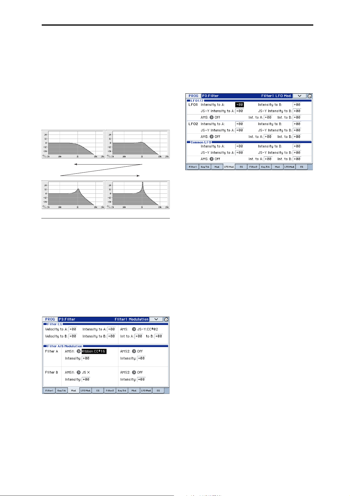
Detailed Editing with Programs Using Filters
Low resonance
High resonance
Resonance
Resonance emphasizes the frequencies around the
cutoff frequency, as shown in the diagram below.
When this is set to 0, there is no emphasis, and
frequencies beyond the cutoff will simply diminish
smoothly.
At medium settings, the resonance will alter the timbre
of the filter, making it sound more nasal, or more
extreme. At very high settings, the resonance can be
heard as a separate, whistling pitch.
To make the resonance track the keyboard pitch, please
see “Key Follow” on page 29 of the Parameter Guide.
Modulating the filters
You can modulate the filter cutoff frequency using the
Filter EG, the LFOs, keyboard tracking, and other
built-in and MIDI controllers. This is a great way to
add a rich variety of tonal change to the sound.
LFO modulation
You can modulate the filter via LFO1, LFO2, and the
Common LFO. Among other applications, LFO
modulation of the filter can produce the classic “autowah” effect.
The Filter1/2– LFO Mod. page lets you set up the
following parameters separately for each LFO:
Intensity to A and Intensity to B specify how much
the LFO changes the tone.
JS-Y Intensity to A and JS-Y Intensity to B specify the
depth of the wah effect produced by the LFO when the
joystick is moved toward yourself, or when CC#2 is
received.
The AMS setting selects an AMS modulation source to
scale the amount of the LFO applied to Filters A and B.
The two filters share a single AMS source, with
separate intensity settings.
For example if AMS is set to SW1: CC#80, turning SW1
on will apply an auto-wah effect (see page 37).
Filter EG
The Filter EG is a multi-stage envelope, which you can
use to modulate the filter as well as other Program
parameters. The EG itself is set up on the EG tab; the
way that it affects the filters is controlled by the
parameters described below, on the Filter1/2–
Modulation page:
The Intensity to A and Intensity to B settings control
the basic amount of EG modulation for filter
frequencies A and B, respectively, before other
modulation.
The Velocity to A and Velocity to B settings let you use
velocity to control the amount of EG modulation.
The AMS setting selects an AMS modulation source to
scale the amount of the Filter EG applied to Filters A
and B. The two filters share a single AMS source, with
separate intensity Into A or to B settings.
Keyboard Track
Most acoustic instruments get brighter as you play
higher pitches. At its most basic application, keyboard
tracking re-creates this effect by increasing the cutoff
frequency of a lowpass filter as you play higher on the
keyboard. Usually, some amount of key tracking is
necessary in order to make the timbre consistent across
the entire range.
The KROME keyboard tracking can also be much more
complex, since it allows you to create different rates of
change over up to four different parts of the keyboard.
For instance, you can:
• Make the filter cutoff frequency increase very
quickly over the middle of the keyboard, and then
open more slowly–or not at all–in the higher
octaves.
• Make the cutoff frequency increase as you play
lower on the keyboard.
• Create abrupt changes at certain keys, for split-like
effects.
How Key Track works: Keys and Ramps
The keyboard tracking works by creating four ramps,
or slopes, between five keys on the keyboard.
For details, please see “How it works: Keys and
Ramps” on page 28 of the Parameter Guide.
39
Page 44
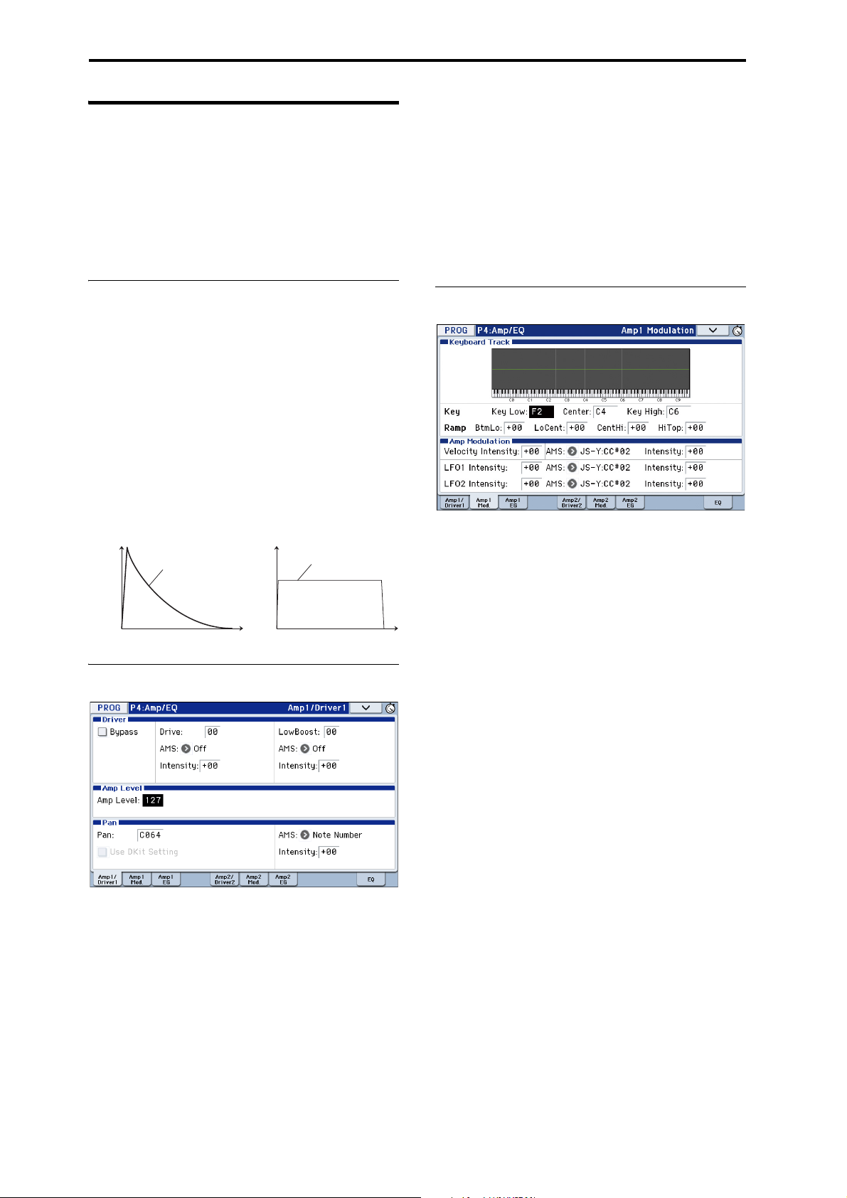
Playing and editing Programs
Volum e
Time
Volume
Time
Piano Organ
Volume decays
gradually
Volume remains constant
until note is released
Using the Amp section
The Amp section includes controls for volume, pan,
and the driver circuit.
You can control the volume using the Amp EG, LFO 1/
2, Key Track, and velocity, along with other AMS
sources.
Each Oscillator has its own Amp section: Amp1 for
OSC1, and Amp2 for OSC2.
Pan - Use DKit Setting
Use DKit Setting applies when Oscillator Mode is set
to Drums or Double Drums.
If this is checked, the Program can use a different pan
position for each drum sound, as specified by the
Drum Kit. If this is unchecked, all drum sounds will
use the Program’s pan position.
The factory presets and GM drum kits use individual
pan positions for the different drums, so normally it’s
best to leave this checked.
Background - what does “Amp”
mean?
Different sounds have characteristic shapes to their
volume levels.
For example, the volume of a piano note begins at a
high volume the instant you play the note, and then
decreases gradually.
The volume of an organ note, on the other hand,
remains constant as long as you continue pressing the
key.
The volume of a note on a violin or wind instrument
can be varied during the note by the musician (i.e., by
regulating the amount of pressure on the bow or the
force of the breath).
Pan
Amp modulation
The basic volume level is set by the Amp Level
parameter. You can then alter this using the
modulation sources below:
Keyboard Track
This lets you vary the volume relative to the note you
play.
For details, please see “Keyboard Track” on page 39.
Amp Modulation
Velocity Intensity is used by most programs to
decrease the volume of softly played notes and
increase the volume of strongly played notes, and the
Amp Modulation parameter adjusts the depth of this
control.
Normally you will set Amp Modulation to positive (+)
values. As this setting is increased, there will be
greater volume difference between softly played and
strongly played notes.
Pan
The main Pan parameter controls the stereo position
after the signal has passed through the oscillator, filter,
and amp.
Normally you’ll set this to C064, so that the sound is
centered equally between the left and right speakers.
To create a stereo effect when Oscillator Mode is set to
Double, set the Amp1/Driver 1 page Pan to L001, and
the Amp2/Driver2 page Pan R127. This will make
OSC1 go to the left speaker, and OSC2 go to the right
speaker.
With a setting of Random, the pan will change
randomly each time you play a note on KROME,
producing an interesting effect.
40
LFO1/2
Specifies how the LFO’s will produce cyclic changes in
volume (tremolo effect).
The volume will be affected by the LFO(s) where you
set an LFO1 Intensity, LFO2 Intensity value.
Intensity (AMS Intensity) adjusts the depth of how the
tremolo effect produced by the LFO will be affected
when you assign an AMS (LFO1 AMS, LFO2 AMS).
For example, if you set AMS to JS-Y: CC #02, tremolo
will be applied when you push the KROME’s joystick
down (toward yourself), or when CC#02 is received.
Page 45

Detailed Editing with Programs Making controller assignments
Piano
Organ
Strings
Amp EG
The Amp EG lets you control how the volume changes
over the course of a note.
Every instrument has its own characteristic volume
envelope. This is part of what gives each instrument its
identifiable character.
Conversely, by changing the volume contour–for
instance, applying a string-like Amp EG curve to an
organ multisample– you can produce interesting and
unusual sounds.
Drive
The Drive circuit adds saturation and overdrive to the
sound, for everything from subtle fattening to drastic
distortion. Unlike an overdrive effect, Drive processes
each voice individually, so the timbre stays the same
regardless of how many voices are being played.
The two main parameters, Drive and Low Boost, work
together to create the overall effect.
Drive controls the amount of edge and bite in the
timbre. Low settings will produce mild saturation, and
higher settings create more obvious distortion.
Often, it’s useful to increase the Low Boost along with
the Drive.
Note: even when the Drive amount is set to 0, the
Drive circuit still affects the timbre. If your goal is a
completely pristine sound, use the Bypass control
instead.
Low Boost is a special low-frequency EQ which
controls the body character of the sound. The specific
EQ frequencies affected will change with the Drive
setting.
Higher amounts increase the bass boost, and will also
intensify the effect of the Drive parameter.
Making controller assignments
Setting the functions of SW1 and SW2
SW1 and SW2 are the two buttons above the joystick.
These on/off buttons can perform a number of different
functions, such as modulating sounds or effects, or
locking the modulation values of the joystick.
Also, each one may work either as a toggle, or as a
momentary switch. In To gg l e mode, each press
alternates between on and off; in Momentary mode,
the switch only changes for as long as you hold it
down.
Each Program, Combination, and Song stores its own
settings for what the buttons will do, and whether each
button is on or off (based on their current states when
the data is saved).
You can set up Panel Switch Assign on the Controllers
Setup page.
Mode Page
Programs Prog P1: Basic/Controllers
Combinations Combi P1: Controllers
Songs Seq P1: Controllers
Note: The on/off status of the SW1 and SW2 buttons
will be preserved when you write the program or
combination.
Note: You can use SW1/2 as alternate modulation or
effect dynamic modulation sources to control program
parameters or effect parameters.
To do so, you will normally assign SW1 Mod.(CC#80)
and SW2 Mod.(CC#81).
For an example of assigning the SW1 button as an
effect dynamic modulation source for a program, and
using it to control an effect, see page 82.
For a complete list of the possible assignments, see
page 348 of the Parameter Guide.
Note: If you want to keep these settings after the power
is turned off, you must save them (see page 116).
41
Page 46

Playing and editing Programs
Setting the functions of Realtime
Controls USER knobs 1–4
When the Realtime controls is set to USER, the four
knobs on the right function as Realtime knobs 1–4.
These can perform a number of different functions,
such as modulating sounds or effects, adjusting effects
send levels, and so on.
Each Program, Combination, and Song stores its own
settings for what the knobs will do.
When using the sliders for AMS or Dmod, it’s
important to understand that creating an assignment is
a two-step process. First, you assign the knob to send a
MIDI controller, such as Knob Mod.1 (CC#17). Second,
you assign that MIDI controller to modulate one or
more Program or effects parameters.
For the first part of the above, use the mode’s
Controllers Setup page (See “Setting the functions of
SW1 and SW2,” above).
The default assignments for knobs 1–4 are Knob Mod.1
(CC#17), Knob Mod.2 (CC#19), Knob Mod.3 (CC#20),
and Knob Mod.4 (CC#21), respectively.
Here’s an example of how to set up knob 1 to control a
Program’s filter and amp EG attack time:
1. Press the MODE PROG button to enter Program
mode.
2. Access the P1: Basic/Controllers– Controllers
Setup page.
Press the PAGE button to access Page Select, and
choose “P1 Basic/Controllers.” Press the Controllers
tab.
3. Press the Realtime Controls Knob Assign “Knob
1–B” popup button, and choose F/A Attack
(CC#73).
4. Press the CONTROL ASSIGN REALTIME
CONTROL button to select USER. (The LED
USER will light up.)
5. Use knob 1 to control the EG attack for the filter
and amp.
For details, please see page 348 of the Parameter
Guide.
Note: If you wish to keep these settings after the power
is turned off, you must save the Program,
Combination, or Song (see page 116).
Arpeggiator settings
According to the note data received from the keyboard
or from the MIDI IN connector, the arpeggiator will
automatically generate a wide range of phrases or
patterns including arpeggios, guitar or keyboard
backing riffs, bass phrases, or drum patterns. When the
realtime controls ARP is selected, you can use the
knobs to vary the duration and dynamics of the
arpeggiated notes.
For more about the arpeggiator, please see page 85.
Drum Track settings
You can use the KROME’s rich variety of drum
patterns to accompany you with high-quality drum
programs while you perform using a program.
Playing along with Drum Track patterns is often a
useful way to come up with new phrases.
For more about the Drum Track function, please see
page 97.
Effects
For details, please see “Using Effects” on page 77.
Automatically importing a Program into Sequence mode
You can use the Auto Song Setup feature, which
automatically copies the settings of the program or
combination and puts the KROME in record-standby
mode when you simply press the REC () button.
Then you can press the SEQUENCER START/STOP
( ) button to begin recording.
For details, please see “Auto Song Setup function” on
page 59.
42
Page 47

Playing and editing Combinations
4: INC/DEC buttons
3: Combination Select
2: COMBI P0: Play
4: VALUE dial
1: COMBI button
4: Numeric keypads
ENTER button
5: BANK SELECT
A–F buttons
1: Mode name
(button)
Mode button Mode, page number
and name
Tab nam e
Combination Select
(Combination number and name)
Category Select popup button
(Category number and name)
Bank
number
Combination Select popup button
About the KROME’s combinations
Combinations let you split and layer up to 16 Programs
at once.
A Combination is made up of 16 Timbres (Note that
you don’t have to use all 16 Timbres). Each Timbre is
assigned a Program, along with parameters for key
range and velocity zones, mixer settings, MIDI channel
and controller filtering, and so on.
Playing combinations
Selecting Combinations
There are several different ways to select
Combinations. Each one is convenient in a different
way:
• Using “Combination Select” and the VALUE
controllers:
• Using the Bank/Combination Select menu:
• Using the Category/Program Select menu:
•Find
• Using a foot switch: page 19
• Sending MIDI program change messages to select
Programs remotely:
For details, please see below.
As with Programs, each Combination has five insert
effects, two master effects, and one total effect for
shaping and transforming the sounds of the individual
Timbres.
This section of the manual takes a quick look at playing
Combinations, including a tour of the front-panel
controllers and basic editing techniques.
Selecting a program using
“Combination Select” and the VALUE
controllers
1. Press the COMBI button. (The LED will light up.)
(Refer to the illustration below for the buttons.)
Alternatively, you can use the mode button (see
“Selecting modes” on page 9).
The KROME will enter Combination mode.
2. Access the Combi P0: Play– Program T01–08 page.
This is shown in the top line of the display.
If a different page is shown, press the EXIT button
several times to move to the Combi P0: Play– Program
T01–08 page.
3. Make sure that “Combination Select” is selected.
If it is not, press “Combination Select” in the display to
highlight it.
4. Select the combination you want to play.
You can use the following methods to select a combination.
43
Page 48

Playing and editing Combinations
Velocity meter
• Use the INC or DEC buttons.
• Turn the VALUE dial.
• Use numeric keys 0–9 to enter the combination
number, and press the ENTER button.
5. Press a COMBI BANK A–D button to switch
banks.
When you select a different Bank, the button’s LED will
light up, and the selected bank will appear on the left
side of the display.
For example, to select bank B, press the COMBI BANK
B button. The B button will light up, and the name
Bank B will appear in the left side of the display.
Auditioning the sound
Play the KROME’s keyboard to hear the combination
you’ve selected.
Key zone preview allows you to check the timbre’s
layer and split settings, as well as how the arpeggiator
is used.
• The keyboard area indicates the last (single) noteon that was received on the global MIDI channel.
• The key zone area shows the timbres that will
sound at the key position, differentiated by several
colors according to the settings of each timbre.
Overview: Combination Banks
With the factory settings, the KROME contains 384
preloaded combinations that are GM2 compatible. In
addition to these, there are 128 combinations to store
sounds that you create, or store optional sound
libraries.
Combinations are organized into four banks as shown
in the following table.
Combination bank contents
Bank Combi. No. Explanation
A, B, C 000...127 Factory Combinations
D 000...127 Initialized Combinations
Selecting by Bank/Combination
Select menu
Green: Timbres that are sounded on the global MIDI
channel, such as by the keyboard.
Yellow: Timbres that will sound only when the
arpeggiator is on (see page 90).
Orange: Timbres that will sound only when the drum
track is on.
Blue: Timbres whose timbre channel is set to
something other than the global channel. These will
not be sounded by the KROME’s keyboard,
arpeggiator, or drum track, but will sound in response
to MIDI note-on messages from an external device.
Purple: These timbres are used to play an external
sound module. They do not sound on the KROME.
None: Timbres whose timbre status is off. These will
not sound.
The velocity meter shows the note-on velocity value.
• Note-on velocities from the keyboard, MIDI IN,
arpeggiator, and drum track are shown for each
timbre/channel. (If multiple note-on events occur
simultaneously, the highest velocity value will be
shown.)
• Since this shows the note-on velocity values, it is
not affected by the setting of the Volume slider nor
by changes in the audio signal level. Also, the meter
will respond even if key zone settings or velocity
zone settings are such that the note is not sounded.
Timbres whose Play/Mute and Solo settings allows
them to play are shown in a dark color, and timbres
that are muted are shown in a light color.
You can select Combinations from a list organized by
Combination bank.
• Press the Combination Select popup button to
access the menu and make your selection.
The selection method is the same as in “Selecting by
Bank/Program Select menu” on page 22; Refer to that
page for details.
Bank/Combination Select menu
44
Page 49

Playing combinations Using controllers to modify the sound
Selecting by Category/Combination
Select menu
You can select Combinations arranged by category,
such as keyboard, organ, bass, and drums.
When shipped from the factory, the preloaded
Combinations are organized into 16 categories, each
with several sub-categories.
• Press the Category Select popup button to access
the menu and make your selection.
The selection method is the same as in “Selecting by
Category/Program Select menu” on page 23; refer to
that page for details.
Category/Combination Select menu
Find
You can search for a combination by a portion of its
name.
The procedure is the same as explained in “Find” on
page 23. Please see that explanation for details.
Using controllers to modify the sound
The KROME provides a variety of controllers that you
can use to vary the sound, such as the joystick, the
SW1, SW2 buttons, and the control surface knobs.
For details, please see the corresponding explanation
for Programs: “Using Controllers” on page 24.
Performing with the arpeggiator or drum track
Based on note data it receives from the keyboard or
from the MIDI IN connector, the arpeggiator can
generate a wide range of phrases and patterns
including arpeggios, guitar or keyboard backing riffs,
bass phrases, or drum patterns. When the realtime
controls ARP is selected, you can use the knobs to vary
the duration and dynamics of the arpeggiated notes.
For more about the arpeggiator, please see page 85.
The Drum Track function uses a rich variety of drum
patterns to play the KROME’s high-quality drum
programs. You can perform along with the drum
patterns, or synchronize Drum Track patterns with the
phrases generated by arpeggiator.
For more about the Drum Track function, please see
page 97.
45
Page 50
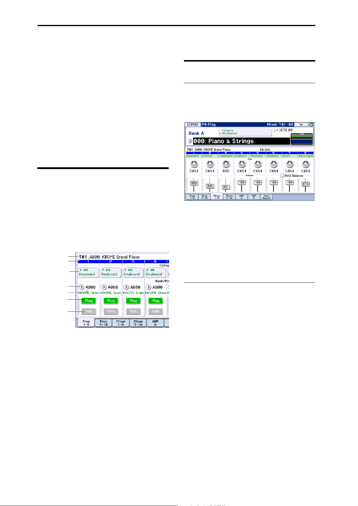
Playing and editing Combinations
Selected
Timbre Info
Timbre No.
Category/Timbre
Program Select
Play/Mute
Solo On/O
Bank/Timbre
Program Select
Program Select
Easy Combination editing
You can edit any of the Combinations shipped with
KROME. You can create your own combinations by
editing a preloaded combination, or by starting from
an initialized combination.
A combination has sixteen timbres; you can assign a
program to each timbre and specify its volume and
pan, the key range in which the program will sound,
and how its sound will be routed to the effects. You can
create simple setups such as detuned sounds, split, or
layers, or highly complex orchestra-like setups.
Even without moving to the various pages for detailed
editing, you can make dramatic changes just from within
the Combi P0: Play page. You can also edit using the
REALTIME CONTROLS knob on the front panel.
Changing the program of each timbre
Adjusting the mix
Adjusting the volume of each timbre
1. Access the Combi P0: Play– Mixer T01–08 page.
This page shows the volume, pan, and Program
assignments for all 8 Timbres.
46
Changing the Programs assigned to timbres (1–16) is a
quick way to dramatically alter the sound of the
Combination.
1. Access the Combi P0: Play– Program T01–08/T09–
16 page.
In this page you can view the program assigned to each
timbre 1–16, and the play/mute and solo status of each.
2. Use any of the following methods to select a
Program for each timbre.
•Choose Program Select, use numeric keys 0–9 to
input the program number, and press the ENTER
button.
•Choose Program Select and turn the VALUE dial or
use the INC/DEC buttons.
•If the Program Select parameter is selected, the
PROG BANK A–F buttons will switch program
banks. (If Timbre Program Select is selected, the
BANK button LED of the program bank selected for
that timbre will light up.)
• From the Bank/Program Select menu you can view
and select programs by bank.
• From the Category/Program Select menu you can
view and select programs by category.
• You can transmit MIDI program changes from a
connected external MIDI device. (See page 361 of
the Parameter Guide)
Note: To select the timbre program via MIDI program
change the timbre’s status must be set to “INT.”
2. In the display, press the timbre 1 volume slider
and slide it up or down to adjust the volume.
You can also highlight the numerical area of the slider
and use the VALUE dial or the numeric keys to adjust
the value.
If you check Hold Balance, moving any one of the
volume sliders (volume values) will cause the volume
of the other timbres to change as well, maintaining the
relative volume balance between timbres 1–16. This is a
convenient way to adjust the overall volume.
Adjusting the panning of each timbre
1. Access the Combi P0: Play– Mixer T01–08 page.
2. Press the timbre 1 pan knob, and slide it left/right
to adjust the panning.
You can also highlight the numerical area of the knob
and use the VALUE dial or the numeric keys to adjust
the value.
Timbre pan interacts with the pan stored in the
Program. A setting of C064 reproduces the Program’s
oscillator pan settings. Adjusting the Timbre Pan will
move the sound to left or right while preserving the
pan relationship between the oscillators. A setting of
L001 is far left, and R127 is far right.
Page 51

Detailed Editing with Combinations Simple editing using the knobs
Parameters
Parameters
Parameters
Parameters
Timbre2
Timbre3
Timbre16
Timbre4
Timbre1
Parameters
Program
Program
Program
Program
Program
AUDIO OUTPUT
L/MONO, R
Master
Eects
1, 2: P9
Total
Eects:
P9
Insert
Eects
1…5: P8
Arpeggio: P7–1, 2, 3, 4, 5
Timbre
Insert Eects
Master Eects
FX Control Bus
Routing: P8-1, 2
DrumTrack: P7–7
Tone Adjust: P0–7
3Band EQ
3Band EQ
3Band EQ
3Band EQ
3Band EQ
Controllers: P1–1
Combination structure and corresponding pages
P1–1, P2–2, etc. indicate the on-screen pages and tabs used when editing on the KROME.
Simple editing using the knobs
You can use the REALTIME CONTROLS to perform a
variety of edits.
For example, you can use the REALTIME CONTROLS
to adjust the Filter cutoff or resonance. You can also use
it to vary the depth of an effect, or to change the way in
which the arpeggiator generates a phrase.
For details, please see “Realtime control knobs” on
page 25.
Saving a Combination you’ve edited
After you’ve edited a combination, you must save it if
you want to keep the changes you’ve made. If you reselect the combination or turn off the power before
saving, your edits will be lost.
1. Press the WRITE button.
The Write Combination dialog box will appear. If you
want to change the writing destination or the name,
make the appropriate changes (see page 117).
2. Press the WRITE button once again to save (write)
the data.
For details, please see “Writing a Program or
Combination” on page 115.
You can also save combinations on an SD card as PCG
files.
For details, please see “Saving to SD card (Media–
Save)” on page 118.
Detailed Editing with Combinations
You can edit the preloaded combinations (Banks A–C)
that the KROME is shipped with, or start with an
initialized Combination to create your own original
sounds.
You can use the factory Programs to create new
Combinations, or use your own custom Programs.
Note: If you’re in the process of editing a Program in
Program mode, and you use that Program in a
Combination, you’ll hear the edited version in
Combination mode as well.
About the edit pages
In the Combi P0: Play page you can select and play
combinations. Here you can also use the REALTIME
CONTROLS knob and the tone-adjust function for
quick editing, or to edit the settings of the arpeggiator
or drum track. In the other pages you can edit the
sound in greater detail.
For details on each mode and how to access each page,
please see “Basic operations” on page 9.
47
Page 52

Playing and editing Combinations
Program B
Program A
Layer:
Two or more programs sound
simultaneously.
Program B
Program A
Split:
Dierent programs will sound in
dierent areas of the keyboard.
Program C
Program D
Program B
Program A
Keyboard playing
dynamics
Strong
Soft
Example:
B and C/D are split. In the lower
keyboard range, A and B are
layered. In the higher keyboard
range, C and D are switched by
velocity and layered with A.
A suggested approach for editing
First, select a Program for each Timbre, on the P0:
Play– Program T01–08 or T09–16 page. (Note that you
don’t have to use all 16 Timbres)
Next, create any desired keyboard or velocity splits,
layers, or crossfades between the different Timbres.
You can do this on the P4: Zone/Delay– Keyboard
Zones page.
After this, adjust the volumes of the Timbres (back on
the Program Select/Mixer tab), and set up any other
Timbre parameters as desired.
To add finishing touches to the sound, set up the Insert,
Master, and Total Effect as desired (on the P8: Routing/
IFX and P9: MFX/TFX/LFO pages, respectively.) These
effects can be different from those associated with the
individual Programs in Program mode, if desired.
In addition, you can make arpeggiator and drum track
settings (on the P7: ART/DT page) and controller
settings (on the P1: Controllers page) to create the
finished Combination.
Soloing timbres
Combi P0: Use the solo function on the Program T0108, T09-16 page to easily hear the sound for each
timbre.
For details, please see “Solo On/Off” on page 72 of the
Parameter Guide.
Restoring edited settings
Using COMPARE
When you’re in the process of editing a sound,
pressing the COMPARE button will recall the saved
version of the sound, as it was before you started
editing.
For details, please see “Compare function” on page 11.
Layers, Splits, and Velocity Switches
Within a Combination, you can use note range and
velocity level to define the “zone” in which a specific
timbre will play.
The Programs assigned to each Timbre can be played
in three ways: as part of a layer, a split, or a velocity
switch. A Combination can be set to use any one of
these methods or to use two or more of these methods
simultaneously.
Layer
Layers cause two or more Programs to play
simultaneously when a note is played.
Split
Splits cause different Programs to respond on different
areas of the keyboard.
Velocity Switch
Velocity Switches cause different Programs to respond
depending on the velocity (how hard you play the
notes).
Program B
Program A
On the KROME, you can use a different Program for
each of up to sixteen Timbres, and combine two or
more of the above methods to create even more
complex setups.
Strong
Keyboard playing
dynamics
Soft
Velocity Switch:
Keyboard playing dynamics
(velocity) switches between
dierent programs.
48
As an additional possibility, you can set the slope for a
key zone or velocity zone so that the volume
diminishes gradually. This lets you change a split into a
keyboard crossfade, or a velocity switch into a velocity
crossfade.
Program A
Program B
Keyboard X-Fade (keyboard
crossfade):
As you play from low notes to
high notes, the volume of A
will fade out, and the volume
of B will fade in.
Page 53

Detailed Editing with Combinations Layers, Splits, and Velocity Switches
C–1 C4 G9B3
PianoTimbre 1
Brass
Timbre 2
Strings
Timbre 3
127
64
63
1
Strings
Velocity
switch
Timbre 1
Timbre 2
Brass
Creating Key Splits and Layers
Splits and Layers
Let’s create a Combination that combines both splits
and layers, like the diagram below:
1. Access the Combi P0: Play– Program T01–08 page.
2. Select a piano sound for Timbre 1, a brass sound
for Timbre 2, and a strings sound for Timbre 3.
3. Access the P3: Timbre Parameters– MIDI T01–08
page.
4. For Timbres 1–3, set Status to INT and MIDI
Channel to Gch (the Global Channel).
Creating Velocity Switches
Next, let’s create a simple velocity switched
Combination, like the diagram below:
1. Access the Combi P0: Play– Program T01–08 page.
2. Select a brass sound for Timbre 1, and a strings
sound for Timbre 2.
3. Access the P3: Timbre Parameters– MIDI T01–08
page.
4. For Timbres 1 and 2, set Status to INT and MIDI
Channel to Gch (the Global Channel).
5. Access the P4: Zone/Delay– Vel Z T01–08 page.
6. Set Timbre 1’s Top Velocity to 127, and its Bottom
Velocity to 64.
You can also enter a velocity value by selecting the
parameter and then playing a note with the desired
velocity on the keyboard while holding down the
ENTER button.
5. Access the P4: Zone/Delay– Key Z T01–08 page.
6. Set Timbre 1’s Top Key to G9, and its Bottom Key
to C4.
You can also enter a note value by selecting the
parameter and then playing the desired note on the
keyboard while holding down the ENTER button.
7. Set Timbres 2 and 3 to a Top Key of B3, and a
Bottom Key of C–1.
Key Zone Slope
In addition to “hard” splits, where the sound changes
abruptly, you can use the Slope parameters to
gradually fade a sound in or out over a range of keys.
In the example above, you could set the Bottom Key of
timbre 1 to G3, and set the Top Key of timbre 2 to G4,
so that these two timbres overlap.
Next, if you set the Bottom Slope of timbre 1 to 12, and
set the Top Slope of timbre 2 to 12, the sound will
change gradually instead of changing suddenly.
7. Set Timbre 2 to a Top Velocity of 63, and a Bottom
Velocity of 1.
Velocity Zone Slope
Similar to Key Zone Slopes, as described above, these
let you fade in and fade out sounds gradually over a
velocity range, instead of a simple hard switch.
In the case of the example above, you could set the
velocity zones of the two Timbres so that they partially
overlap. Then, set the Top Slope and Bottom Slope so
that the sound changes gradually, instead of changing
suddenly between velocity values of 63 and 64.
49
Page 54

Playing and editing Combinations
MIDI settings
Timbre Parameters MIDI page
Status
This controls the status of MIDI and the internal tone
generator for each Timbre. Normally, if you’re playing
an internal Program, this should be set to INT.
If the status is set to Off, EXT, or EX2, that Timbre’s
internal sounds will not be played. Off simply disables
the Timbre entirely. The EXT and EX2 settings allow
the Timbre to control an external MIDI device.
For details, please see “Status” on page 81 of the
Parameter Guide.
Bank Select (when status=EX2)
When the Status is set to EX2, these parameters allow
you to transmit MIDI Bank Select messages to external
MIDI devices.
MIDI filter settings
For each MIDI Filter item, you can specify whether or
not the corresponding MIDI message will be
transmitted and received. The checked items will be
transmitted and received.
The MIDI filters don’t turn the functions themselves on
or off. Instead, the filter just controls whether or not
that MIDI message will be transmitted and received.
For example, if portamento is on, portamento will be
applied to the internal KROME sound even if Enable
Portamento SW is unchecked.
As another example, let’s say that you’ve selected a
bass Program for Timbre 1, and a piano Program for
Timbre 2, with the goal of creating a bass/piano split.
You could choose the following settings so that
pressing the damper pedal affects only Timbre 2’s
piano sound:
1. Access the P5–1: MIDI Filter <1> T01–08 page.
2. Un-check the Enable Damper box for Timbre 1.
3. Check the Enable Damper box for Timbre 2.
MIDI Channel
Timbres that you wish to play from the KROME’s
keyboard must be set to the global MIDI channel. Your
playing on the keyboard is transmitted on the global
MIDI channel, and will trigger any timbre that matches
this channel. Normally you will set this to Gch. When
this is set to Gch, the MIDI channel of the timbre will
always match the global MIDI channel, even if you
change the global MIDI channel.
On some preloaded Combinations, Timbres used
by the arpeggiator may have their MIDI Channels
set to something other than Gch. These will be
timbres that play only when the arpeggiator is on,
which is a very useful technique for creating
“A p re gg i at or b as ed” Combinations.
For details, please see “Arpeggiator settings in
Combination and Sequencer modes” on page 89.
In particular, note the relationships between
arpeggiator A/B assignments and MIDI Channel.
50
Page 55

Detailed Editing with Combinations Altering Programs to fit within a Combination
Altering Programs to fit within a Combination
You can make various changes to Programs within the
context of a particular Combination to make them fit
better with other Programs, or to create particular
sonic effects. These changes do not affect the original
Programs, or how those Programs sound in other
Combinations (see page 81 of the Parameter Guide).
Timbre Parameters: OSC
Force OSC Mode
If you wish to force a polyphonic program to sound
monophonically, set this either to MN (Mono) or LGT
(Legato). Conversely, set this to Poly if you wish to
force a monophonic program to play polyphonically.
Normally this should be set to PRG, so that the sound
will play as set by the original Program.
For details, please see “Force OSC Mode” on page 82 of
the Parameter Guide.
Timbre Parameters: Pitch
Transpose, Detune (BPM Adjust)
These parameters adjust the pitch of the timbre.
• In a layer-type combination, you can set two or
more timbres to the same program, and create a
richer sound by using Transpose to shift their pitch
apart by an octave or by using Detune to create a
slight difference in pitch between the two.
•In split-type combinations, you can use Transpose
to shift the pitch (in semitone units) of the
programs specified for each key zone.
Note: If you wish to change the playback pitch of a
drum program, use Detune. If you change the
Transpose setting, the relationship between the notes
and drum sounds will change.
Use Program’s Scale, Scale
This specifies the scale for each timbre.
If you check Use Program’s Scale, the scale specified
by the program will be used. Timbres where this
parameter is not checked will use the Scale setting.
OSC Select
If the timbre is using a Program where the Oscillator
Mode is Double or Double Drums, and you want only
OSC1 or OSC2 (not both) to sound, set this to OSC1
(only OSC1 will sound) or OSC2 (only OSC2 will
sound).
Normally, this should be set to BTH (Both).
Portamento
If the Program uses portamento, but you’d like to
disable this for the current Combination, set this
parameter to Off.
Conversely, if you want to force the portamento to be
on, or just to change the portamento time, set this to a
value of 001–127. The portamento will change to use
the newly specified time.
Normally, this should be set to PRG.
51
Page 56
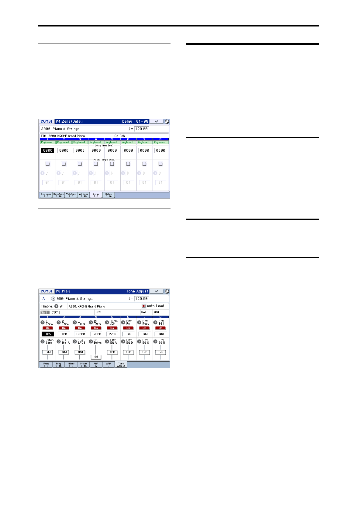
Playing and editing Combinations
Delay
You can set some Timbres so that they don’t sound
immediately at note-on. This can create cool effects,
and more dramatic layers.
You can specify the delay for each Timbre either in
milliseconds (ms), or in rhythmic values which sync to
the system tempo.
If you set the Delay to Key Off, the Timbre will sound
when the note is released.
Editing Programs with Tone Adjust
Using Tone Adjust, you can create detailed edits to
Programs within the context of the Combination.
These edits will not affect the original Program, or any
other Combinations which use the Program. To edit a
Program with Tone Adjust:
Select a timbre in the Timbre field of the P0: Play– Tone
Adjust page. Then select the parameter that you want
to adjust, and use the VALUE controllers to edit the
sound.
Arpeggiator settings
According to the note data received from the keyboard
or from the MIDI IN connector, the arpeggiator will
automatically generate a wide range of phrases or
patterns including arpeggios, guitar or keyboard
backing riffs, bass phrases, or drum patterns. If the
SELECT button is set to ARP, you can use the knobs to
vary the duration and dynamics of the arpeggiated
notes.
For more about the arpeggiator, please see page 85.
Drum Track settings
While you perform using a combination, you can use
the KROME’s rich variety of drum patterns to play
high-quality drum programs.
Playing along with Drum Track patterns is often a
useful way to come up with new phrases.
For more about the Drum Track function, please see
page 97.
Effects
For details, please see “Using Effects” on page 77.
Automatically importing a Combination into Sequencer mode
The Auto Song Setup feature automatically applies the
settings of the current Combination to a song.
For details, please see “Auto Song Setup function” on
page 59.
52
Page 57

Creating songs (Sequencer mode)
Overview
About the KROME’s Sequencer
The sequencer brings together the KROME’s numerous
functions such as its arpeggiator, RPPR, highperformance effects, and controllers, allowing you to
take advantage of these in a wide range of situations.
This sequencer is a 16-track MIDI sequencer that can
store up to 128 songs and 210,000 MIDI events. You can
use it to record and play back notes for the internal
sound generator as well as for external MIDI sound
modules.
When you turn off the power, the settings created
in Sequencer mode, the song data, any user
pattern data, and Cue List that you recorded will
not be backed up. If you wish to keep this data,
you must save it on an SD card before turning off
the power, or perform a MIDI data dump to save
the data on an external data filer etc.
If you wish to write the programs, track
parameters, effects, and arpeggiator settings etc.
selected for a song as a template song, use the
menu command Save Template Song.
Immediately after the power is turned on, KROME
will not contain any song data, so if you wish to
play a song on the sequencer, you must first load
data from SD card, or receive a MIDI data dump
from a MIDI filer. For details, please see page 118,
and page 219 of the Parameter Guide.
Sequencer mode structure
Sequencer mode is structured as follows.
Songs
A song consists of tracks 1–16, a master track, song
parameters such as the song name, arpeggiator, Drum
Track function, effect and RPPR parameters, and 100
user patterns.
A maximum of 128 such songs can be created on
KROME.
Tracks 1–16 consist of setup parameters (such as each
track’s program, pan, and volume) located at the start
of the song, and the musical data itself. The master
track consists of tempo and time signature data (see
“Setup parameters & Musical data” on page 106 of the
Parameter Guide).
Song recording and editing
Song recording is performed on tracks.
You can record tracks in either of two ways; realtime
recording or step recording. For realtime recording
you can choose one of six recording modes.
You can edit tracks by using Event Edit operations to
modify the recorded data or insert new data, and by
using Track Edit functions such as Create Control Data,
which generates and inserts pitch bend, aftertouch, or
control change data.
Patterns
There are two types of patterns: preset patterns and
user patterns.
Preset patterns: Patterns suitable for drum tracks are
preset in internal memory, and can be selected for any
song.
User patterns: Each song can have up to 100 patterns.
When using a pattern in a different song, use the menu
commands Copy Pattern or Copy From Song etc. to
copy the pattern. The pattern length can be specified in
units of a measure.
Each pattern consists of musical data for one track. It is
not possible to create patterns that contain multiple
tracks.
You can use these patterns by placing them in a track
(Put to Track menu command) or by copying them
(Copy to Track menu command). You can also use
patterns with the RPPR function of a song (see
page 71).
53
Page 58

Creating songs (Sequencer mode)
RECLOCATE START/
STOP
PAUSE
REW
FF
RECLOCATESET
LOCATE
<, >
popup
START/
STOP
PAUSE REW FF
Recording and editing a pattern
You can record a pattern in either of two ways: realtime
recording or step recording. However, unlike realtimerecording to a track, you can select only one recording
type (loop recording) when realtime-recording to a
pattern.
You can edit the pattern to correct mistakes in the
recorded data, or use event editing to insert new data.
You can use the Get From Track menu command to
obtain a desired region of performance data from a
track and use it as pattern data. Conversely, you can
use the Put to Track or Copy to Track menu
commands to place or copy a pattern’s performance
data into a track.
How Sequencer patterns are related to Drum
Track patterns
The patterns of the Drum Track function you use with
a Program or Combination are related to Sequencer
mode patterns as follows.
Preset patterns are a common library that can also be
used by the Drum Track function.
User patterns cannot be directly used by the Drum
Track function, but they can be converted to user Drum
Track patterns and used with a Program or
Combination. If you convert a user pattern, it will be
stored in internal memory, and this data will not
disappear even when you turn off the power.
Cue List
The cue list allows you to playback multiple songs in
succession. The KROME lets you create twenty cue
lists. Each cue list lets you connect up to 99 songs and
specify the number of times that each song will repeat.
The menu command Convert to Song lets you convert
the songs in a cue list into a single song.
For example you can use a cue list to create the
backing, convert the cue list to a song, and then add
solo phrases on unused tracks.
PAUSE ( ) button
This button pauses the playback of the song. When
paused, the button’s LED will light up. Press PAUSE
( ) once again to resume playback, and the LED will
turn off.
REW ( ) button
When the Song is playing or paused, this button will
rewind the song. When you press and hold this button,
its LED will light up, and the playback will rewind.
(Rewind is disabled during recording, and while the
Song is stopped.)
Note: You can use the FF/REW Speed menu command
to specify the fast-forward and rewind speed.
FF ( ) button
When the Song is playing or paused, this button will
fast-forward the song. When you press and hold this
button, the button will light up, and the playback will
fast-forward. (Fast-forward is disabled during
recording, and while the Song is stopped.)
LOCATE ( ) button
By pressing the LOCATE ( ) button you can move to
a specified locate point. By default, you’ll move to
001:01.000.
To change the locate point that’s assigned to the
LOCATE ( ) button, use the menu command Set
Location. Alternatively, you can set the locate point
during playback by holding down the ENTER button
and pressing the LOCATE ( ) button.
START/STOP ( ) button
This starts or stops recording and playback in
Sequencer mode.
REC ( ) button
Pressing this button will enter record-ready mode.
Once you’re in record-ready mode (shown by the
button’s lit LED), you can begin recording by pressing
the SEQUENCER START/STOP ( ) button. For
details, please see “Recording MIDI in real time” on
page 60.
54
Transport control
These controls let you play back, record, fast-forward,
or rewind the sequencer.
Front panel buttons
You can use the front panel SEQUENCER buttons to
control recording and playback on the sequencer.
Buttons in the display (the transport
bar)
The transport buttons in the bottom line of the display
can also be used to control sequencer recording and
playback in the same way as the front panel
SEQUENCER buttons.
The transport buttons will appear when you press the
“<” button on the lower right side of the display and
drag it toward the left. To close them, press the “>”
button and drag it toward the right.
Page 59

Playing Songs
Popup
Location
Song Position Bar
Track Select
Song Select
Meter Tempo
Program Select,
& Popup
Category
Track 2
Solo
Play/Mute/Rec
Track 1
Playing Songs Playback
Playback
In order to play back song data in the sequencer, you
must first record, load or dump song data into the
KROME.
Let’s start by loading and playing the demo song data.
For details, please see “Listening to the demo songs”
on page 21 of the Quick Start Guide.
1. Press the SEQ button or MODE button to enter
Sequencer mode.
The P0: Play/REC– Program T01–08 or T09–16 page
will appear. If this is not displayed, press the EXIT
button about three times.
2. Use “Song Select” to select the song you want to
play back.
You can press the Song Select popup button and
choose from a list. If you select an empty list, a new
song will be created.
You can also select a song by using the INC/DEC
button or VALUE dial. However if there is no song,
you can’t make a selection using the VALUE
controllers.
Changing the volume, mute, and solo
settings of each track
In the SEQ P0: Play/REC– Prog T01–08, T09–16, Mixer
T01–08, and T09–16 pages you can change the volume,
mute, and solo settings of each track.
Muting a specific track/Monitoring a
specific track (Mute/Solo functions)
The KROME provides a Mute function that lets you
silence specified tracks 1–16, and a Solo function that
lets you hear the specified track or channel by itself.
These functions can be used in various ways. For
example you can intentionally mute or solo specific
tracks, or listen only to the rhythm section of the
previously-recorded tracks while you record new
tracks. Let’s try out the Mute and Solo functions.
1. Use “Song Select” to select the song that you want
to play back.
2. Press the SEQUENCER START/STOP ( )
button.
3. Press track 1 Play/Rec/Mute.
The display will change from Play to Mute, and the
playback of track 1 will no longer be heard. In this way,
the “mute” function allows you to silence a specified
track until the track is un-muted.
Press track 2 Play/Rec/Mute. The display will change,
and the playback of track 2 will also be muted. To
cancel muting, press Play/Rec/Mute once again.
3. Press the SEQUENCER START/STOP ( )
button.
Alternatively, pull out the transport bar and press the
START/STOP ( ) button. The transport control
functionality in the procedure below is described as
button operations, but you can also perform the same
operations using the on-screen transport buttons.
The song you selected in step 2 will begin playing.
Note: The song will begin playing if you press the
START/STOP ( ) button in a page other than P10:
Pattern/RPPR. If you press this button while you’re in
P10: Pattern/RPPR, the currently-selected pattern will
begin playing. (In P11: Cue List, the songs of the cue
list will be played.)
4. During playback, you can press the START/STOP
( ) button to stop playback.
If you press the START/STOP ( ) button once
again, playback will resume from where you stopped.
For details on the functions of the LOCATE ( ),
PAUSE ( ), REW ( ), and FF ( ) buttons, please
see page 54.
You can use the FF/REW Speed menu command to
specify the fast-forward and rewind speed.
4. Press track 1 “Solo On/Off.”
“Solo” will be highlighted, and this time, only the
performance of track 1 will be heard. To play back only
a specified track by itself in this way is known as
“soloing” the track (turning Solo on).
If both Mute and Solo are used, the Solo function will
be given priority.
Press track 2 “Solo On/Off.”
The display will change, and you will hear the
playback of tracks 1 and 2. You won’t hear the sound of
tracks 3–16.
5. To switch Solo off, press Solo On/Off once again.
Press Solo On/Off for both tracks 1 and 2.
The display will change, and the playback of tracks 1
and 2 will be muted. If the Solo function is turned off
for all tracks, playback will be according to the Play/
Rec/Mute settings.
The SOLO setting is not stored when you save the
song.
55
Page 60

Creating songs (Sequencer mode)
Loop Start
Measure
Play Intro
Track Play Loop
Loop End
Measure
Exclusive Solo
Exclusive Solo is a function that limits the Solo
function (described above) to a single track at a time. If
Exclusive Solo is on, only the track for which Solo was
last turned on will be played; other tracks will always
be silent.
Use the Exclusive Solo menu command to specify how
the Solo function will function.
Exclusive Solo off: You will be able to solo more than
one track at a time. The status of a track will change
each time you press its Solo On/Off button.
Exclusive Solo on: When you press a Solo On/Off
button, only that track will be soloed.
Tip : You can turn Exclusive Solo on/off by holding
down the ENTER button and pressing numeric key 1.
Loop playback
When recording or playing back a song, you can loop
individual tracks that are playing.
In the P0–1: Play Loop T01–08 or T09–16 page, check
Track Play Loop for the tracks you want to loop, and
use Loop Start Measure and Loop End Measure to
specify the starting and ending measure of the region
that will play back as a loop.
If you check Play Intro, the measures preceding the
loop will be played back as an introduction before the
loop begins.
56
If you play back from the first measure with the
settings shown in the screenshot above, the specified
region of measures will repeat as follows.
Measures 1 2 3 4 5 6 7 8 9 10 11 12 13
Track 1 1234567856785
Track 2 9109109109109109109
If Play Intro is unchecked, the specified region of
measures will repeat as follows.
Measures 1 2 3 4 5 6 7 8 9 10 11 12 13
Track 1 5678567856785
Track 2 9109109109109109109
Page 61

Recording
Popup
Track Select
Location
Song Select
Meter
REC Resolution
Tempo
Tempo
Mode
Program Select,
& Popup
Category
Solo
Play/Mute/Rec
Recording Preparations for recording
Preparations for recording
Before you begin recording, make sure that the
memory protect setting in Global mode is turned
off. For details, please see “Protecting the
memory” on page 110.
Creating a Song
Before we can begin this example, we need to select an
empty song where we can record.
1. Press the SEQ button or MODE button to enter
Sequencer mode.
2. Choose “Song Select” (e.g., in the P0: Play/REC–
Program T01–08 page).
You can press the Song Select popup button, and
choose from a list.
Track settings
Since we’re going to record a new song in this example,
we will start by explaining how to assign a program to
each track, and adjust basic settings such as volume.
1. Assign a program to each track.
Use “Program Select” to assign a program to each
track. The method is the same as when assigning a
program to a timbre in a combination (see page 46).
You can copy various settings from Programs or
Combinations. (See pages 166, 167 of the Parameter
Guide.)
2. When assigning a program, you can use Track
Select to choose the track to which you wish to
assign a program, and audition the sound.
3. Set the pan and volume of each track.
Press the Mixer 1–8 tab (or the Mixer 9–16 tab) to access
the Mixer T01–08 page (Mixer T09–16 page).
3. Use the numeric keys to input the number of the
new song that you want to create, and press the
ENTER button. (For example, press the 1 switch
and then the ENTER button.) A dialog box will
appear.
If you pressed the Song Select popup to access the
Song No. dialog box, press the desired song number to
open the dialog box.
4. Use “Set Length” to input the desired number of
measures and press the OK button.
You can change the number of measures later if
desired. For details, please see “Set Song Length” on
page 176 of the Parameter Guide.
5. Press the OK button to create the song.
Tip : You can use the ENTER button instead of the OK
button.
• Pan sets the pan position of each track, and Vo l u me
sets the volume level of each track.
4. Specify the tone generator and MIDI channel that
will be played by each track.
Press the PAGE button to access SEQ Page Select, and
press “P3 Track Parameters” The P3: Track Parameters
page will appear. Press the MIDI 1–8 tab (or the MIDI
9–16 tab) to access the MIDI T01–08 page (MIDI T09–16
page).
•Use Status to specify whether each track will play
the internal and/or external sound generator.
Normally when using the KROME, you will select INT
or BTH.
INT: During playback, the KROME’s internal tone
generator will play the MIDI data recorded on that
track. When you use the KROME’s keyboard or
57
Page 62
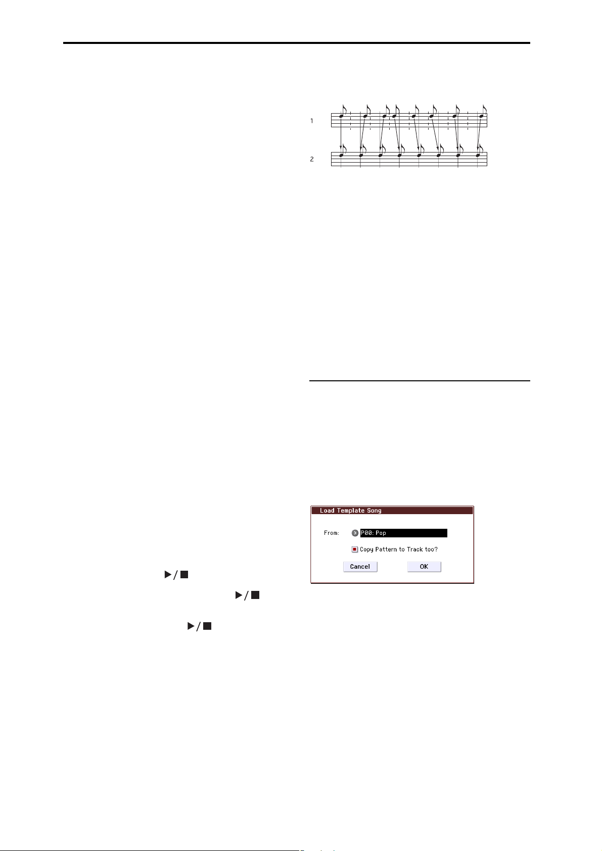
Creating songs (Sequencer mode)
controllers, you will be playing and controlling the
track selected by Track Select.
EXT, EX2, BTH: During playback, the MIDI data
recorded on that track will be transmitted from MIDI
OUT to play an external sound module. When you use
the KROME’s keyboard or controllers, MIDI data will
be transmitted to play and control the external sound
module selected by Track Sel e c t . (The MIDI channel of
the external tone generator must be set to match the
MIDI Channel of KROME tracks that are set to EXT,
EX2 or BTH.)
If Status is set to BTH, both the external tone generator
and internal tone generator will be played and
controlled.
•Use MIDI Channel to specify the MIDI channel for
each track.
Normally you will set the MIDI Channel to a
different channel: 1–16 for each track. Tracks that
are set to the same MIDI channel will sound
simultaneously when you record or play back
either of the tracks.
5. Adjust the effect settings.
Adjust settings for each effect in P8: Routing/IFX and
P9: MFX/TFX/LFO.
For details, please see “Using effects in Combinations
and Songs” on page 81.
6. Set the tempo and time signature.
• To set the tempo, you can turn the TEMPO knob or
press the TAP button at the desired interval.
Alternatively, you can select (Tempo) in the P0:
Play/REC– Program T01–08 page (or similar page),
and use the VALUE controllers to set the tempo. Set
Tempo M o de to Manual.
• Next you will set the time signature. In this
example, we’ll explain how to set the time signature
using the “Meter” field. Normally, you specify the
time signature before recording the first track, and
then begin recording.
a) Press the SEQUENCER REC () button, and set “Meter”
to **/**.
b) Press **/** to highlight it, and use the VALUE controllers
to set the time signature.
c) Press the START/STOP ( ) button to begin
recording. When the pre-count has ended and Locate
reaches 001:01:000, press the START/STOP ( )
button to stop recording. The time signature you
specified has now been recorded on the Master track.
If you press the START/STOP ( ) button during the
pre-count, the time signature won’t be recorded.
7. Set the “REC Resolution” if necessary.
When you record in real time on a track, this parameter
specifies how the timing of the recorded MIDI data
will be corrected. The timing will also be corrected
when you record automation data in real tme on an
audio track. (Data that was already recorded will not
be corrected.)
For example, let’s suppose that you recorded some
eighth notes in real time, but your timing was not quite
perfect, as shown in part 1 of the illustration below. If
REC Resolution were set to when you recorded, the
timing would automatically be corrected as shown in
part 2 of the illustration. If REC Resolution is set to Hi,
the notes will be recorded with the timing at which
you play them.
8. Make other settings as necessary.
You can adjust the settings for the arpeggiator (P7:
ARP/DT), MIDI filtering (P5: MIDI Filter), etc. (See
page 89)
You may also wish to use Tone Adjust to tweak the
sound. When you are finished making these settings,
the basic setup is complete.
Saving your song parameter settings
The song parameter settings you create here can be
saved as a template. If you use these settings
frequently, you can simply load one of the templates
you’ve saved.
For details, please see “Save Template Song (Save as
User Template Song)” on page 164 of the Parameter
Guide.
Using template songs
Loading a template song is an easy way to create
settings appropriate for a particular musical style. You
can also assign a drum pattern to a track at the same
time.
1. In the P0: Play/REC page, press the menu
command button and choose “Load Template
Song.”
A dialog box will appear.
2. In the “From” field, choose the template song you
want to load.
3. If you check “Copy Pattern to Track too?”, a dialog
box for copying a pattern will automatically
appear after you execute the “Load Template
Song” operation.
If you execute the command without checking this,
only the template song you selected in step 2 will be
loaded.
4. Press the OK button to load the template song, or
press the Cancel button if you decide to cancel.
When you perform this operation, song settings other
than track Loop and RPPR will be copied.
If you executed this operation with Copy Pattern to
Track too? checked in step 3, the Copy Pattern To
Track dialog box will appear.
58
Page 63

This dialog box is the same as the one that appears for
the Copy To Track (P10: Pattern/RPPR– Pattern Edit)
menu command.
5. In the “Pattern” field, select the pattern that you
want to copy.
In the To Track field, select the copy-destination track.
In the Measure field, specify the starting measure of
the copy-destination.
Following the pattern name for each of the 605 preset
patterns, the musical style and the name of the most
suitable Drums category program are partially
displayed.
By loading a drums track and the corresponding preset
pattern, you can instantly set up a drum track
appropriate for each preset template song.
6. To execute this operation, press the OK button.
When you execute this procedure, the Measure field
will count up automatically, showing how many
measures of the selected pattern have been placed in
the selected song. You can then copy another pattern if
desired, or add more measures of the same pattern.
When you’re finished, press the Exit button.
Copying the settings of a combination
or program
You can copy the settings of a combination or program
into the sequencer.
This can be done in the following ways.
•Auto Song Setup
Auto Song Setup is a function that copies the
settings of the selected combination (in
Combination mode) or program (in Program mode)
to the song in Sequencer mode.
• Menu commands Copy From Combi or Copy From
Program. (See pages 166, 167 of the Parameter
Guide)
In Sequencer mode, you can use these page menu
commands to copy the desired settings.
Recording Preparations for recording
Auto Song Setup function
1. Enter Combination mode.
2. In P0: Play page, select the desired combination
and edit the Arpeggiator etc. as desired.
Note: If you want to save the edited state of the
combination, use the Write Combination menu
commands.
3. Press the REC () button. Alternatively, select the
page menu command “Auto Song Setup.”
The Setup to Record dialog box will appear.
4. To execute the Auto Song Setup function, press the
REC () button or the OK button. If you decide
not to execute, press the Cancel button.
You will automatically move to Sequencer mode, and
the settings of the combination will be copied to the
song.
The first unused song will be the copy-destination
song.
Contents automatically copied from a combination
The copied contents will be the same as when you
execute the menu command Copy From Combi with
the following settings in the dialog box. (See page 166
of the Parameter Guide)
• IFXs, MFXs, TFX checked
• Auto Adjust Arp setting for Multi REC checked
Contents automatically copied from a program
The copied contents will be the same as when you
execute the menu command Copy From Program with
the following settings in the dialog box. (See page 167
of the Parameter Guide)
• IFXs, MFXs, TFX checked
• Arp checked
• To set to Track 01
• Arp set to A
• with Drum Track checked
• To: Drum Track set to Track 10
• Check Recording Setup Multi REC
• Set the Play/Rec/Mute setting to REC for tracks 01
and 10 (see page 101 of the Parameter Guide).
5. The KROME will automatically enter record-ready
mode, and the metronome will sound according to
the Metronome setting (See page 119 of the
Parameter Guide).
6. Press the START/STOP ( ) button to begin
realtime recording. To stop recording, press the
START/STOP ( ) button once again.
59
Page 64

Creating songs (Sequencer mode)
Recording MIDI in real time
When you’ve finished with “Preparations for
recording,” you can start recording.
This is a method of recording what you’re playing on
the keyboard and your controller usage, in real time.
This method of recording is normally used one track at
a time, and is called single track recording.
As an alternative, multitrack recording allows you to
simultaneously record multiple channels of data onto
multiple tracks. This is the method you will use when
using the Drum Track function, the RPPR function, and
the arpeggiator to record multiple tracks of musical
data at once, or when you play back existing sequence
data on an external sequencer and record it onto
KROME’s sequencer in real time.
5. When you finish playing, press the START/STOP
( ) button.
Recording will end, and the location will return to the
point where you begin recording.
If you press the PAUSE ( ) button instead of the
START/STOP ( ) button, recording will pause.
When you press the PAUSE ( ) button once again,
recording will resume where you left off before
pausing. When you are finished, press the START/
STOP ( ) button to stop recording.
The following recording setup parameters are also
available.
Overdub
Select this method if you wish to record additional
performance data by overdubbing it without erasing
the previously-recorded data.
Recording setup
In P0: Play/REC– Preferences page Recording Setup,
select the realtime recording method you want to use.
Overwrite
By default, this recording method is selected.
This will record your performance by overwriting any
previously recorded data. All data following the
measure where you start recording will be erased.
Normally you will use this method to record, and then
modify the results by using other types of real-time
recording or MIDI event editing.
1. Use Track Select to choose the track that you want
to record.
2. Set the Recording Setup to Overwrite.
3. In “Location,” specify the location where you wish
to begin recording.
Location
Manual punch-in
Select this method when you wish to use the
SEQUENCER REC () button or a foot switch to re-
record selected portions of a previously-recorded
track.
Auto punch-in
Select this method when you wish to automatically rerecord selected portions of a previously-recorded
track.
Then, recording will occur only over the specified area
(Auto Punch In Start Measure–Auto Punch In End
Measure), rewriting it with the newly recorded data.
Loop All Tracks
Select this method when you wish to repeatedly record
over a specified area of a track, while continuing to add
data. This is suitable for creating drum patterns, etc.
For details, please see “An example of realtime
recording” on page 61.
Multi (multitrack recording)
Use MIDI multi-track recording if you want to
simultaneously record multiple tracks of different
channels, such as when recording the output of the
drum track, arpeggiator or RPPR functions, or when
recording from an external multi-track sequencer.
4. Press the SEQUENCER REC () button, and then
press the START/STOP ( ) button.
If the Metronome Setup is still set to the default
settings, the metronome will sound for a two-measure
pre-count, and then recording will begin.
Play the keyboard and move controllers such as the
joystick to record your performance.
60
Page 65

Recording Step recording
Bass drum: C3
Snare: E3
Hi hat: F#3
An example of realtime recording
In this example, we’ll assign a drum program to track
01 and create the following one-measure drum phrase.
1. Create a new song, and specify a drum program
for track 01.
Use Track Select to select track 01, and verify that you
hear a drum program. (See page 57)
2. Access the P0: Play/REC– Preferences page. In
Recording Setup, specify “Loop All Tracks” and
set it to M001-M001 (see page 117 of the Parameter
Guide).
With this setting, measure 1 will be recorded
repeatedly. The newly recorded data will be added at
each pass.
3. Set “REC Resolution” to . (See page 58)
4. Press the SEQUENCER REC () button, and then
the START/STOP ( ) button.
The metronome will sound a two-measure countdown, and then recording will begin.
5. As shown in the musical example printed above,
start by playing the C3 note of the keyboard to
record the bass drum for one measure.
6. Next, play the E3 note of the keyboard to record
the snare for one measure, and then the F#3 note to
record the hi-hat.
7. Press the START/STOP ( ) button to stop
recording.
8. Play back the result, and listen to the drum
performance that you recorded.
Press the START/STOP ( ) button. When you’ve
finished listening, press the START/STOP ( )
button once again to stop playback.
9. If you’re not satisfied with the result, press the
COMPARE button to return to the state prior to
recording, and then re-record from step 4.
Note: When you’re finished recording, change the
Recording Setup back to the normally-used Overwrite
(P0: Play/REC– Preferences page).
In addition, access the P0: Play/REC– Play Loop T01–
08 page, check Track Play Loop for track 01, and set the
Loop Start Measure and Loop End Measure to 001.
When you play back, track 01 will repeatedly play the
first measure.
Step recording
Step recording is the recording method where you
specify the duration and strength of each note, and use
the keyboard to specify the pitch of each MIDI note.
You can use the Rest button and Tie button of the
dialog box to input rests and ties.
Step recording is useful when you want to create
mechanically precise beats, or when you need to
record a phrase that would be difficult to play by hand
“in real time,” or when you find it difficult to play
extremely complicated or rapid passages.
An example of step recording
In this example, we’ll assign a bass program to track 02
and step-record the following two-measure bass
phrase.
Step
Note
Time:
Select
C3 . C3 key
G3 - G3 key
C4 - C4 key
C4 - C4 key
D3 - D3 key
Eb3 - Eb3 key
E3 - E3 key
F3 - F3 key
C3 - C3 key
F2 - F2 key
Tie - Tie button
F2 - F2 key
A2 - A2 key
A3 - A3 key
1. Specify a bass program for track 02. Use Track
Select to select track 02, and verify that you hear a
bass program.
2. Access the P6: Track Edit– Track Edit page.
Step
Time:
. 3 -
Key, Button
- Rest button
- Rest button
- Rest button
- Rest button
- Rest button
- Rest button
Measure/
Beat Tick
001 / 01.000
001 / 01.360
001 / 02.000
001 / 02.240
001 / 02.360
001 / 03.120
001 / 03.240
001 / 04.000
001 / 04.240
002 / 01.000
002 / 01.120
002 / 01.360
002 / 02.000
002 / 02.240
002 / 03.000
002 / 03.240
002 / 03.360
002 / 04.000
002 / 04.240
002 / 04.360
61
Page 66

Creating songs (Sequencer mode)
3. Set “From Measure” to 001.
With this setting, step recording will begin from
measure 1.
4. Press the menu command button, and press menu
command “Step Recording.”
A dialog box will appear.
5. In “Step Time,” use “Select” to specify the basic
timing value.
Input the first C3 note as . (dotted eighth note).
Use the popup button to the left to select .
You can choose a note value ranging from a whole note
() to a 32nd note ().
Input a dotted note by selecting “.” with the popup
buttons at right.
You can specify “3” to input a triplet. If you want to use
the unmodified length of the note that’s selected at the
left, choose “–”.
“Note Duration” indicates the length that the note
itself will sound. Smaller values will produce a staccato
note, and larger values will produce a legato note. For
this example, leave this setting unchanged.
“Note Velocity” is the velocity (playing strength), and
larger values will produce a louder volume. Set this to
Key.
If you select Key for this parameter, the velocity of how
you actually play the keyboard will be input.
6. On the keyboard, press and then release the first
C3 note that you want to input.
The data you input will appear in the display as
numerical values. On the upper right side, Measure
001 Beat Tick 01.000 will change to Measure 001 Beat
Tick 01.360. The next note you input will be placed at
this location.
7. As described in steps 5 and 6, input the notes and
rests that follow the first C3 note.
In addition to the methods described in steps 5 and 6,
you can also use the following input methods.
• To input a rest, press the Rest button. This will
input a rest of the selected Step Time value.
• To enter a tie, so that two or more notes of the same
pitch will be played as a single unbroken note,
press the Tie button. When you press the Tie
button, the previously-input note will be extended
by the Step Time length.
• To delete a note or rest that you input, press the
Step Back button. The previously-input note will be
deleted.
• To input a chord, simultaneously press the notes of
the desired chord. Even if you do not press them
simultaneously, notes that are pressed before you
fully remove your hand from all keys on the
keyboard will be input at the same location.
• To audition a note without actually inputting it,
press the PAUSE ( ) button. Now when you play a
note on the keyboard, it will sound, but the note
will not be actually input. In this state, playing a
key will produce a sound, but will not input a note.
Press the PAUSE ( ) button once again to cancel
the record-pause state, and resume inputting notes.
8. When you are finished recording, press the Done
button.
Press the SEQUENCER START/STOP ( ) button
to play back.
Access the P0: Play/REC– Play Loop T01–08 page,
check Track Play Loop for track 02, set Loop Start
Measure to 001, and Loop End Measure to 002. track
02 will play measures 1–2 repeatedly.
9. If you’re not satisfied with the result, press the
o
COMPARE button to return t
recording, and then re-record from step 4.
When you begin step recording, all data in the
track that follows the measure where you began
recording will be erased. You need to be aware of
this if you begin step recording from a measure
mid-way through the song.
If you want to copy data into a measure that
already contains data, perform step recording in
an empty track, and use the Move Measure or
Copy Measure menu commands. (See page 179 of
the Parameter Guide)
If you want to edit or add to the recorded data, you
can use the Event Edit or Piano Roll function. (See
pages 169, 171 of the Parameter Guide)
the state prior to
62
Page 67

Recording Recording multiple tracks from an external sequencer
Recording multiple tracks from an external sequencer
The playback from an external MIDI sequencer
connected to the KROME can be recorded
simultaneously using multi-recording.
1. Make sure that the MIDI OUT of your external
sequencer is connected to the MIDI IN of the
KROME.
If it is not connected, turn off the power, make the
connection, and then turn the power on.
2. In the Global P1: MIDI– MIDI Basic page, set
MIDI Clock to External MIDI. With this setting,
the KROME will synchronize to MIDI clock
messages from your external sequencer.
Make sure that Receive Ext. Realtime Commands is
checked.
3. Create a new song in Sequencer mode, and in the
P0: Play/REC– Preferences page, check the Multi
REC check box. Set Recording Setup to Overwrite.
5. In the P3: Track Parameters– MIDI T01–08 and
T09–16 page, use MIDI Channel to specify the
MIDI channel of each track.
Set the MIDI channel of each KROME track to match
the MIDI channel of each external sequencer track.
Data from each channel will be recorded on the
corresponding KROME track.
Make sure that Status is set to INT or BTH.
6. Press the LOCATE ( ) button to set the location
to 001:01.000.
7. Press the SEQUENCER REC () button to enter
record-standby mode.
8. Start your external sequencer.
The KROME’s sequencer will automatically begin
recording when it receives the MIDI Start message
transmitted by your external sequencer.
9. When playback has ended, stop your external
sequencer.
The KROME’s sequencer will automatically stop
recording when it receives the MIDI Stop message
transmitted by the external sequencer. You can also
stop recording by pressing the START/STOP ( )
button on the KROME.
After this, you can play back the newly recorded
sequence:
10. In the Global P1: MIDI– MIDI Basic page, set
MIDI Clock to Internal.
Set Tempo M o de to Auto in the Seq P0: Play/REC–
Program T01–08 page.
Press the START/STOP ( ) button to play back.
Note: If the correct sounds are not selected when you
start playing back, you may be able to solve the
problem by using the menu command Event Edit (P6:
Track Edit) to re-specify the Program Change data.
4. Press Play/Rec/Mute to select “REC” for the tracks
you want to record.
For the tracks you don’t want to record, select Play or
Mute.
63
Page 68

Creating songs (Sequencer mode)
Recording System Exclusive events
Exclusive messages received from an external MIDI
device or the parameter changes produced when you
edit a track parameter or effect parameter can be
recorded in real time on any track.
During playback, the exclusive messages you recorded
will control the track parameters and effect parameters
of the song, and can be sent to external MIDI devices.
Note: You can use the menu command Put Effect
Setting to Track to insert an exclusive event containing
the parameter settings for an insert effect, master effect
or total effect into the desired location of a track, so
that these settings will automatically switch during
playback.
GM, XG, and GS exclusive messages can be
recorded on a track, but the KROME’s tone
generator will not respond to these messages.
Recording internal parameter
changes
You can use SysEx for automation of internal KROME
effects and Program parameters.
Here we’ll explain how to record internal parameter
changes. As an example, we’ll explain how parameter
changes recorded on a different track can be used to
modify the parameters of the insert effect (IFX1)
applied to the program of track 1.
Note: In order to record system exclusive messages,
make sure that the Global P1: MIDI– MIDI Routing
setting Enable Exclusive is checked. Go to Global
mode and verify that this is checked.
2. Select Track 09 in “Track Select,” and record
parameter changes as desired.
Note: For this example, select an empty track. If you
want to record onto a MIDI track that already contains
data, set the P0: Play/REC– Preferences page
Recording Setup to “Overdub,” as described on
page 60.
• Select Track 09 in Track Select. Then press the
SEQUENCER REC () button and then the START/
STOP ( ) button, and begin recording.
• At the appropriate time while recording, adjust the
parameter(s) that you want to realtime-record.
In the P8: Routing/IFX- Insert FX Setup page, select
another effect for IFX1, and modify the effect
parameter values.
1. Select the desired program for MIDI track 1, and
route it to IFX1. Then record a phrase of about
sixteen measures.
• In the P0: Play/REC– Program T01–08 page, use
“Program Select” to select the desired program for
MIDI Track 01.
• In the P8: Routing/IFX– Routing T01–08 page, route
the MIDI Track 01 Bus (IFX/Output) Select to IFX1.
Then in the P8: Routing/IFX– Insert FX Setup page,
select the desired effect for IFX1.
• Select MIDI Track 01 in Track Select. Then press
the SEQUENCER REC () button and then the
START/STOP ( ) button, and record a phrase
of about sixteen measures.
64
Note: In addition to effect parameter changes, you can
also record parameters such as sound parameters. For
details on the parameters that can be recorded, please
see page 191 of the Parameter Guide.
3. Stop recording.
Note: Exclusive messages are always recorded on the
current track selected by Track Selec t . In this example,
they are recorded on MIDI track 9.
Note: In the MIDI event edit page you can view the
recorded exclusive events and their location. Exclusive
events are displayed as “EXCL”.
To view these events, go to the P6: Track Edit– Track
Edit page, and select the menu command MIDI Event
Edit. Then in the Set Event Filters dialog box, check
Exclusive and press the OK button.
Exclusive events cannot be changed to a different
type of event. Nor can other events be changed
into exclusive events.
4. If you go to the page (e.g., P8: Routing/IFX) that
shows the parameters you adjusted in realtime,
you can watch the recorded changes be reproduced
while the song plays back.
Page 69

Exclusive messages that will be recorded
Pattern Select
Track
Select
Remove Data
REC Resolution
during realtime recording
The following exclusive messages will be recorded.
(See page 191 of the Parameter Guide)
• Exclusive messages received from an external MIDI
device.
• Parameter changes in Sequencer mode.
• Master Volume universal system exclusive
messages assigned to a foot pedal or knob.
Using realtime controls to record
changes in a MIDI track’s pan, EQ,
volume, and tone adjust
By controlling the pan, EQ, volume, and tone adjust
parameters during realtime recording, you can record
these changes so that they will be reflected during
playback.
Use multi-track recording if you want to modify the
settings of multiple tracks simultaneously.
Note: Controlling these parameters will transmit
control change or system exclusive messages. In order
for this data to be recorded, the Global P1: MIDI– MIDI
Routing Enable Control Change and Enable Exclusive
settings must be checked. Go to Global mode and
verify that these items are checked.
Note: Use Param. MIDI Out in Global P1: MIDI Basic
page to specify whether control change messages or
system exclusive messages will be transmitted when
you edit the Pan (CC#10), Volume (CC#7), or Send 1/2
level (CC#93 and CC#91) parameters.
In this case, the Global P1: MIDI– MIDI Routing
settings Enable Control Change and Enable Exclusive
must be checked respectively.
Recording Recording patterns
Recording patterns
Recording and editing patterns
You can record patterns in either of two ways; realtime
recording or step recording. However, pattern realtime
recording differs from song realtime recording in that
you can use only Loop type recording.
You can edit patterns by using Event Edit operations to
modify the recorded data or insert new data. You can
also use the Get From Track menu command to
convert a desired region of performance data from a
MIDI track into a pattern. Conversely, you can use the
Put to Track or Copy to Track menu commands to
place or copy the performance data from a pattern into
a MIDI track.
In addition, you can use the “Convert to Drum Track
Pattern” page menu command to convert a user
pattern to a drum track pattern. (See “Converting to a
Drum Track pattern” on page 103)
Recording patterns in real time
When realtime-recording a pattern, a pattern of the
specified number of measures will play back
repeatedly, allowing you to continue adding musical
data to it.
1. Create a new song, and as described in
“Preparations for recording” on page 57, set the
track to the program that will be used by the
pattern.
2. Access the P10: Pattern/RPPR– Pattern Edit page.
3. Use Track Select to choose the track that you will
use to record the pattern.
The pattern will play back with the program and other
settings of the selected track.
4. Set “Pattern (Pattern Bank)” to User, and set
“Pattern Select” to U00.
User patterns U00–U99 can be created for each song.
5. Select the menu command “Pattern Parameter”.
65
Page 70

Creating songs (Sequencer mode)
A dialog box will appear.
Other way to record
Using the Drum Track function and
the arpeggiator to record on multiple
tracks simultaneously
6. Set the number of measures in the pattern to a
“Length” of 04 (four measures), and set “Meter” to
a time signature of 4/4. Press the OK button.
7. As necessary, set “REC Resolution” to apply
realtime quantization.
8. Begin realtime recording.
You can record in the same way as you did when
recording tracks with Loop All Tracks. (See “Loop All
Tracks” on page 60)
Press the SEQUENCER REC () button, and then press
the START/STOP ( ) button.
After the pre-count, pattern recording will begin. Play
the keyboard and use the joystick and other controllers
to record your performance.
When you reach the end of the pattern, the sequencer
will return to the beginning of the pattern and continue
recording. If you continue recording, the newly
recorded data will be added to the previouslyrecorded data.
9. If you want to delete specific data while you
continue pattern recording, you can press the REC
() button or check the “Remove Data” check box.
For details refer to step 6 of “Loop All Tracks” on
page 60.
10. Press the START/STOP ( ) button to stop
recording.
If you made a mistake or decide to re-record, press the
START/STOP ( ) button to stop recording, and
press the COMPARE button. Then begin the pattern
recording procedure again as in step 8.
You can use multi-recording to simultaneously record
a multi-track performance using the Drum Track
function and arpeggiator.
For details, please see “Recording MIDI in real time”
on page 60.
Using the RPPR function to record on
multiple tracks simultaneously
You can use multi-recording to simultaneously record
a multi-track performance using the RPPR function.
For details, please see “Creating an RPPR pattern” on
page 71.
66
Page 71

Song editing
Song editing Song
You can apply a variety of editing procedures to a
song. The available types of editing procedures are
listed below.
Song
Load (Save) Template Song: Loads a song template
into the song (or saves a song as a template) (see
page 58).
Copy From Combination/Copy From Program:
the settings of the specified combination/program to the
settings of the song that’s currently selected.
Copy From Song: This command copies all of the
setting data and musical data from the specified song
to the song that’s currently selected.
Rename song: Renames the selected song. You can
enter up to 24 characters.
Delete Song: This command deletes the currently
selected song.
FF/REW Speed: This allows you to set the speed at
which fast-forward or rewind will occur when you
press the FF ( ) button or REW ( ) button.
GM Initialize: This command transmits a GM System
On message to the Sequencer mode, resetting all MIDI
tracks to the GM settings.
Set Song Length: This command changes the length of
the specified song. When it is executed, the length of
the master track will change, and the number of
measures played will change.
Copies
MIDI tracks
Tracks
Step Recording: This allows you to specify the length
and velocity of each note numerically, and to input
MIDI data, the pitches, from the keyboard. You can use
the Rest button and Tie button to enter a rest or tie.
Event Edit: Here you can edit individual events of
MIDI data.
Piano Roll: Allows you to edit notes, velocities, and
control changes in the piano roll screen. By selecting
and dragging events in the screen, you can edit their
pitch or timing, or delete or add events.
Erase Track: This command erases the data from the
specified track. It is not possible to erase the master
track by itself.
Copy Track: This command copies musical data from
the copy source track to the specified track.
Bounce Track: This command combines the musical
data of the bounce source and bounce destination
tracks, and places the combined data in the bounce
destination. All musical data in the bounce source will
be erased.
Erase Measure: This command erases the specified
type(s) of musical data from the specified range of
measures. The Erase Measure command can also be
used to remove only a specific type of data. Unlike the
Delete Measure command, executing the Erase
Measure command does not cause the subsequent
measures of musical data to be moved forward.
Delete Measure: This command deletes the specified
measures. When the Delete Measure command is
executed, the musical data following the deleted
measures will be moved towards the beginning of the
sequence.
Insert Measure: This command inserts the specified
number of measures into the specified track. When you
execute the Insert Measure command, the musical data
following the insert location will be moved backward.
Repeat Measure: This command repeatedly inserts the
specified measures for the specified number of times.
When you execute the Repeat Measure command, the
measures will be inserted following the measure
specified by To End of Measure, and musical data
following the inserted data will be moved backward.
Copy Measure: This command copies the measures of
musical data specified as the “From” source to the
beginning of the measure specified as the “To”
location. When you execute the Copy Measure
command, the existing track data at the copy
destination will be rewritten.
Move Measure: This command moves the specified
measures of performance data to another measure.
When you execute the Move Measure command, the
performance data following the move-source measures
will move forward by the corresponding number of
measures, and the performance data following the
move-destination will move backward (i.e., later in the
song) by the same number of measures.
Create Control Data: This command creates control
change, aftertouch, pitch bend, or tempo data in the
specified region of a MIDI track or the master track.
Erase Control Data: This command erases data such as
control changes, aftertouch, pitch bend, or tempo in
the specified range.
Quantize: This command corrects the timing of MIDI
data of the type you specify (note data, control change,
aftertouch, pitch bend, program change, etc.) in the
track.You can also adjust for swing.
Shift/Erase Note: This command shifts (moves) or
erases the specified note numbers in a specified MIDI
track and range of measures.
Modify Velocity: This command modifies the velocity
values of notes in the specified area so that they will
change over time according to a selected curve.
Create Exclusive Data: This command creates
universal system exclusive messages or KROME
parameter change messages in the specified region of a
MIDI track.
Erase Exclusive Data: This command erases (deletes)
versal system exclusive messages or KROME
uni
parameter change messages from the specified region.
To delete all types of system exclusive message other
than those listed above, set the Erase Measure
command’s “Kind” field to Exclusive, and execute the
command.
67
Page 72
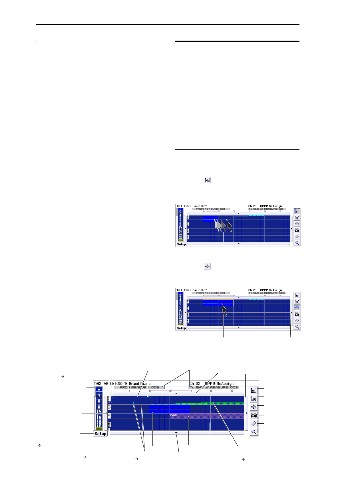
Creating songs (Sequencer mode)
Track View area select
The bar at left indicates the
four tracks shown in the track
view area (in this example,
tracks 1–4).
Setup
Press this button to open
the Track View Setup
dialog box.
Displays note events in a
one-octave range
Displays the values for the
control message name indicated
in the left of the screen
Indicate the selected region.
Linked with the identicallynamed parameter of the
Track Edit page.
( Track View Setup)
Track name indication
Control message name indication
(
Track View Setup)
Scroll button
Selected region
Velocity indication
(
Track View Setup)
(
Track View Setup)
(
Track View Setup)
Scroll button
Scroll button
Note events
Location bar
Track view area
Pattern
Too l bo x
Jump to the piano roll.
Specify the starting
measure.
Specify the ending
measure.
Move the events of the
selected measure(s).
Copy the events of the
selected measure(s).
Erase the events of the
selected measure(s).
1
2
34
Pattern
Step Recording (Loop Type): Here you can perform
step recording into a pattern.
Event Edit: Here you can edit individual events of the
musical data in a pattern.
Piano Roll: You can edit notes, velocities, and control
changes in the piano roll screen.
Pattern Parameter: This command specifies the
number of measures and the time signature of the
selected pattern.
Erase Pattern: This command erases the data from the
selected pattern.
Copy Pattern: This command copies the settings and
musical data of the selected pattern to another pattern.
Bounce Pattern: This command combines the musical
data of the bounce source pattern and bounce
destination pattern, and places the combined musical
data in the bounce destination.
Get From Track: This command takes musical data
from a MIDI track and loads it into the specified
pattern.
Put To Track: This command places a pattern into a
MIDI track.
Copy To Track: This command copies the specified
area of musical data from the specified pattern to a
MIDI track as musical data.
Convert to Drum Track Pattern: This command
converts a user pattern into a user drum track pattern,
which can then be used with the Drum Track in any
mode.
Load Drum Track Pattern: This command loads a user
Drum Track pattern into a user pattern.
Erase Drum Track Pattern: This erases the specified
Drum Track pattern.
Track view edit
Here we’ll explain track view editing.
You can visually specify regions of measures in the
display, and then move, copy, or erase them.
For each track, event data such as notes, velocities, and
control changes are displayed (see the illustration
below).
Your editing will apply to the highlighted measures.
The range is shown in FROM MEASURE and To END
of MEASURE in the upper line.
You can move, copy, or erase data in units of measures.
Note: You can’t specify a region of measures unless a
tool is selected in the toolbox.
Examples of using the tools
Example)
Moving the events of measures 1–2 to measures 5–6
1. Press the tool.
2. Drag over measures 1–2 to specify the edit region.
3. Press the tool.
4. Press measure 5 (the move-destination measure).
Alternatively, drag the edit region to measure 5.
68
Page 73
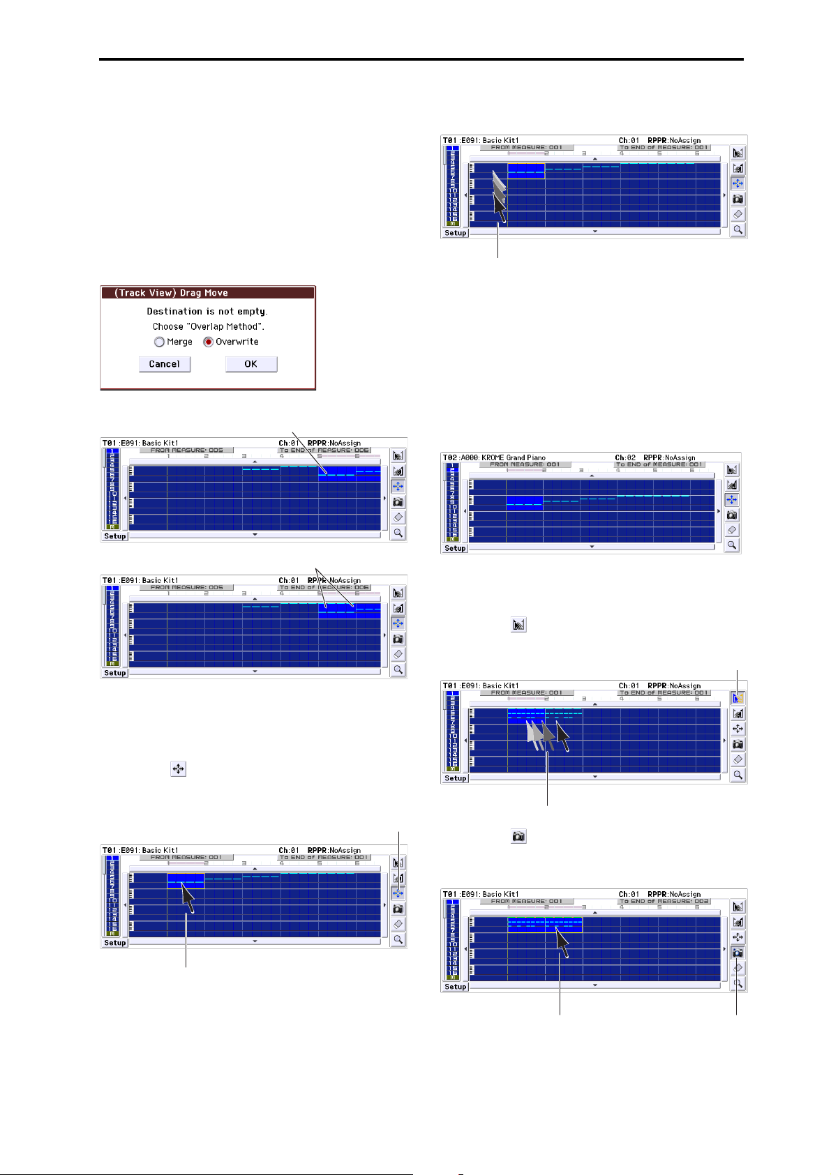
Song editing Track view edit
The destination is overwritten
by the source data
If you choose Overwrite
The two sets of data are combinedIf you choose Merge
2
3
4
1
2
5. In this example, an event exists in the movedestination measure, so the Drag Move dialog box
will appear.
Overwrite will overwrite the source data over the
destination data (replacing the destination data with
the source data). Merge will combine the source and
destination data.
Press the OK button to execute the move.
If there are no events in the move-destination
measures, this dialog box will not appear; the move
will occur immediately.
4. While continuing to press, drag to the movedestination track, and release.
If the move-destination measures contain events, the
Drag Move dialog box will appear.
Overwrite will overwrite the source data over the
destination data (replacing the destination data with
the source data). Merge will combine the source and
destination data. Press the OK button to execute the
move.
If there are no events in the move-destination
measures, this dialog box will not appear; the move
will occur immediately.
Example)
Moving the data of an entire track
1. Return the location to the beginning.
2. Press the tool.
3. Press the left side of measure 1 in the track you
want to move.
Example)
Copying the events of measures 1–2 to measures 3–4
1. Press the tool.
2. Drag over measures 1–2 to specify the edit region.
3. Press the tool.
4. Press measure 3 (the copy-destination measure).
Alternatively, drag the edit region to measure 3.
34
69
Page 74
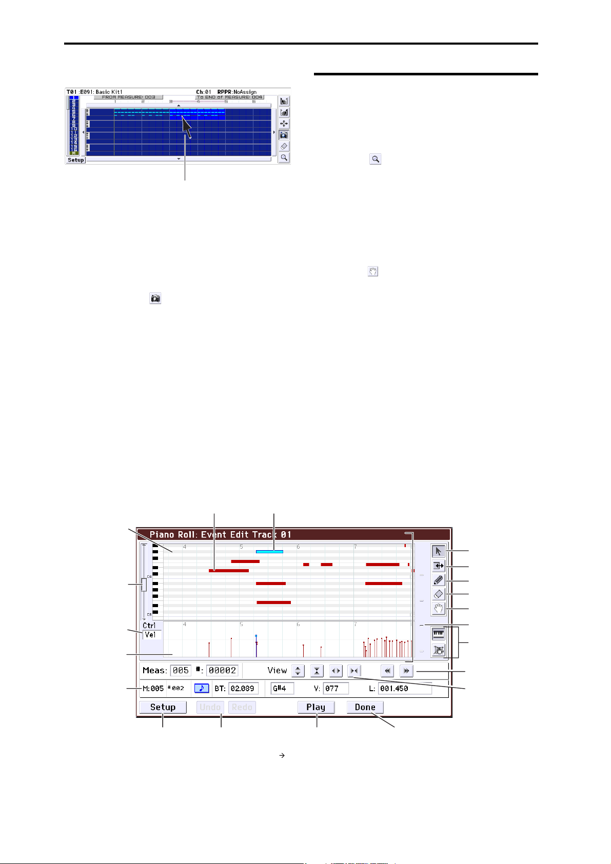
Creating songs (Sequencer mode)
5
The copy will be executed.
5. If desired, you can press another copy-destination
to copy the data repeatedly.
Example) Copying the data of an entire track
You can copy the data of an entire track to another
track.
Refer to “Example) Moving the data of an entire track.”
In step 2, choose the tool.
Piano Roll Editing
Piano Roll editing lets you enter, edit, or delete event
data such as notes, velocities, and control changes.
1. In the Seq P6: Track Edit- Track View page, specify
the track and measure that you want to edit.
2. Select the tool in the Track View page or select
“Piano Roll” from the menu commands to access
the Piano Roll window. (See illustration below)
3. Make sure that the events you want to edit are
displayed in the note view area at the upper part
of the window or in the control view area at the
lower part of the window.
• Press the note view area selector, and use the value
controllers.
• Select the tool, and drag.
• Enter “Meas” or “#” in the event list.
• Use the view control zoom buttons to zoom-in/out.
• Switch the view area height selector.
4. Use the tool box to select a tool, and edit the data.
Note: If you want to undo an edit, press the Undo
button.
5. To play back the events, press the Play button. A
dialog box will open, and the song will start
playing. This allows you to check the results of
your editing.
6. You can change settings such as the note
resolution. Press the Setup button, and adjust the
settings in the Piano Roll Setup dialog box.
7. When you’re finished editing, press the Done
button.
Note view area
Note view area select
Select what will be
shown in the control
view area. (In this
example, velocity values
are shown.)
Control view area
Event list
The Piano Roll Setup dialog
box will appear when you
press the Setup button
(->see Piano Roll Setup).
Note events
Undo cancels the
preceding edit. Redo
returns to the state prior
to Undo.
The selected note event
Plays back the song. The Piano Roll
Edit Play dialog box will appear
when you press this button
( Piano Roll Edit Play).
Ends piano roll editing
Toolbox:
Select or move a note.
Change the length of notes.
Enter notes.
Delete notes.
Move the note view
area that is displayed.
View area height select
Switch the note event
display
Scroll (view control)
Zoom
70
Page 75

Creating an RPPR pattern
RPPR stands for Realtime Pattern Play/Recording, and
is a function that lets you assign pattern data to each
key, and then play back that pattern simply by pressing
the key where it is assigned. You can realtime-record
this performance.
Creating RPPR data
1. Create a new song, and choose a drum program for
track 1.
2. Access the P10: Pattern/RPPR– RPPR Setup page.
In this page, the RPPR function is automatically
turned on.
3. Select the key where the pattern will be assigned.
4. Select C#2.
You can also change this setting by holding down the
KEY edit cell and playing a note on the keyboard.
Note: C2 and lower keys are used to stop playback,
and cannot be assigned patterns.
5. Check “Assign” for C#2.
6. Set “Pattern Bank” to Preset, and set “Pattern
Select” to P001.
7. Set “Track” to Track01.
The selected pattern will be played according to the
settings (program, etc.) of the track you select here.
8. Assign patterns to other keys.
For “KEY,” press the INC button to select D2.
9. Press the Revert button.
The Assign, Pattern Bank, Pattern Select, and Track
settings will be given the previously (steps 5–7)
specified values.
10. Choose “Pattern Select,” and press the INC
button to select P002.
By using Revert in this way, you can work efficiently
when assigning contiguous (or nearby) pattern
numbers or tracks.
Creating an RPPR pattern Creating RPPR data
• As described above, assign several other patterns
such as P003 and higher.
11. Press the C#2 key.
The assigned pattern will play.
12. Take your finger off the C#2 key, and press the D2
key.
The pattern will change, and playback will begin. At
this time, the pattern operation will depend on the
Sync and Mode setting.
13. Set KEY to C#2, and set Sync to Measure. Make
the same setting for D2.
Now press the notes consecutively. Notice that the
patterns function in a different way.
With the Measure setting, patterns will be handled in
one-measure units. The second and subsequent
patterns will start in sync with the end of pattern that
was previously played.
If you change the Mode setting to Once, the entire
pattern will playback to the end even if you release
your finger from the keyboard immediately.
• To stop playback, either press the same key once
again, or press the C2 or lower key.
For details on Sync, Mode, and Shift, please see
page 158 of the Parameter Guide.
• The assigned keys are also shown in the keyboard
graphic in the display.
• Keys where no patterns are assigned can be played
normally. Use Track Select to select the track you
want to play. For example you could assign backing
patterns for drums or bass to keys C#2–B2 and use
these keys to control the pattern playback, while
using the keys C3 and above to play a solo
performance in realtime. It’s a good idea to keep
your RPPR assignments within a specific range of
keys.
71
Page 76

Creating songs (Sequencer mode)
RPPR On
RPPR playback
Let’s use the RPPR pattern that you created to perform
in the P0: Play/REC– Program T01–08 page.
1. Access the P0: Play/REC– Program T01–08 page.
2. Check the “RPPR” check box.
The RPPR function will be turned on. Set the RPPR on/
off for each song.
3. Play the keyboard, and patterns will begin playing
according to the RPPR settings.
If you want to play RPPR phrases from an external
MIDI device, you can control them on the MIDI
channel of the track that’s selected in Track Select.
• Pattern playback for keys where the Sync setting is
Beat or Measure will synchronize to the pattern
playback of the very first key played.
• If you are playing the pattern in synchronization
(when Sync is Beat, Measure, or SEQ), the pattern
will start accurately if you play the note slightly
earlier than the timing of the beat or measure. Even
if you play the note slightly later than the beat or
measure (but no later than a 32nd note), it will be
considered to have started at the beat or measure,
and the beginning of the pattern will be
compressed so that the remainder of the playback
will be correct.
4. To turn off the RPPR function, uncheck the RPPR
check box.
Realtime-recording an RPPR performance
You can record the realtime performance generated by
RPPR.
Recording an RPPR performance
The RPPR playback can be recorded as performance
data on the track(s) assigned to each pattern. This
means that you’ll use either single track recording or
multi-track recording, as appropriate for the track
settings or performance style of the RPPR you’re
playing.
On the other hand, even if RPPR uses only one track,
use multi-track recording if you will be recording
another track at the same time.
You should also select multi-track recording if you
specified the RPPR data using multiple tracks rather
than just a single track, and want to simultaneously
record the performance of multiple tracks.
Here’s how you can record an RPPR performance and
a keyboard performance at the same time. Before you
continue, use the P0: Play/REC– Program T01–08 page
to assign a drum program to MIDI track 1, and a bass
program to MIDI track 2.
1. Assign several keys starting with C#2 to preset
patterns.
Check the C#2 Assign setting, and set Pattern Bank to
Preset and Pattern Select to the desired preset pattern.
For Track, select MIDI track 1 (Track 01) to which you
assigned a drum program.
2. For each RPPR pattern, set Sync to SEQ.
With a setting of SEQ, RPPR patterns triggered while
the sequencer is playing or recording will start in
synchronization with the measures of the sequencer.
(See page 158 of the Parameter Guide.)
Play RPPR while a song plays back
RPPR can be played in synchronization with the
playback of a song.
Pattern playback for a key with a Sync setting of SEQ
will synchronize to the playback of the song. Start the
song playback, and then press the key. The pattern
playback will start in synchronization with the
measures of the song.
Synchronization will be lost if you use the REW
( ) or FF ( ) buttons while a song is playing.
Note: If you want RPPR pattern playback to begin at
the moment that song playback begins, it is a good
idea to insert an empty measure containing no musical
data before the song playback begins.
Note: If the song is stopped, the pattern will
synchronize to the timing of the arpeggiator.
72
3. Access the P0: Play/REC– Program T01–08 page.
4. Check the “RPPR” check box, and set Track Select
to MIDI Track 02.
If the RPPR check box is selected, the RPPR function
will be turned on even in pages and tabs other than
RPPR Setup, allowing you to perform with the RPPR
function by pressing a key to which an RPPR is
assigned.
Note: In the note range C#2 and above, keys to which
no pattern has been assigned can be played to sound
the program of the MIDI track selected by Tra ck
Select.
Page 77

Creating an RPPR pattern Realtime-recording an RPPR performance
5. Since you want the tracks you play via RPPR and
the track you play from the keyboard to be
recorded at the same time, check the Multi REC
check box.
Note: If Recording Setup is set to Loop All Tracks, it
will not be possible to select Multi REC. Set the
Recording Setup to Overwrite (see page 60).
6. Press the SEQUENCER REC () button to enter
record-ready mode.
7. For the tracks you will be recording (MIDI Track 1,
2), press Play/Rec/Mute to make them indicate
REC.
Make sure that the tracks you’re not recording are
indicated as Play or Mute.
8. Press the LOCATE ( ) button to set the location
to 001:01.000.
9. Press the START/STOP ( ) button, and then
press a key that plays an RPPR pattern.
Then press the key where the RPPR pattern playback is
assigned.
If the key where the RPPR is assigned is pressed
during the pre-count before recording, RPPR pattern
playback will start the moment that recording begins
after the pre-count.
Record the RPPR pattern playback and keyboard
performance.
When recording the playback of patterns triggered
by RPPR, the timing of the recorded events may be
slightly skewed. If this occurs, try setting REC
Resolution to a setting other than Hi.
10. When you are finished performing, press the
START/STOP ( ) button.
Recording will end, and the sequencer will return to
the location where recording began.
If you made a mistake during your performance or
would like to re-record, you can use the Compare
function (press the COMPARE button) to re-record as
many times as you wish.
11. If you want to record other tracks, un-check the
Multi REC (See step 5) or “RPPR” (See step 4)
check boxes as necessary.
73
Page 78

Creating songs (Sequencer mode)
Step
Song
Repeat
S000: Intro
S001: A
S002: B
S003: Chorus
S001: A
01
02
03
04
05
06
S002: B
02
02
01
02
02
01
S003: Chorus
S001: A (Solo)
S003: Chorus
S004: Ending
07
08
09
10
02
01
03
02
Cue List
Intro
Intro A A B Chorus
Chorus
AA
B Chorus
Chorus
A(Solo) Chorus Chorus Chorus
Ending
Ending
Song Position Bar
Creating and playing a Cue List
A cue list allows you to play multiple songs in
succession. You can create the individual sections of a
song, such as the intro, melody A, melody B, chorus,
and ending, and then use a Cue List to assemble these
sections into a song by specifying the desired order
and the number of repetitions for each section. You can
then edit the cue list to efficiently try out different
structures for your song.
You can also use this as a jukebox function that will
play back completed songs in the order you specify.
Creating a cue list
Each unit in a cue list is called a “step,” and each step
contains a song number and the number of repeats.
For example, suppose you’ve created the songs S000:
INTRO, S001: VERSE, and S002: CHORUS. Let’s use a
cue list to connect these songs together.
1. Access the Seq P11: Cue List page.
With the default settings, song S000 will be selected for
“Step” 01, and End will be selected for “Step” 02.
3. Set the last step to End.
If you set this to Continue to Step01, the cue list will
play back repeatedly.
4. In “Repeat,” specify the number of times that the
song for that step will be repeated. For this
example, set Step 02 S001: VERSE to 02.
5. Specify whether effect settings will also be
switched when the song at each step is played
back. If you want effect settings to change, check
the “Load FX?” check box.
For this example, check the “Load FX?” check box for
Step 01, which loads the effects.
6. To play back at the tempo that was specified for
each song, set “Tempo Mode” to Auto.
If this is set to Manu (Manual), playback will use the
tempo specified by “ =”.
7. When you press the SEQUENCER START/STOP
( ) buttonh, playback will begin from the
step that is specified as the “Current Step.”
74
2. Add a song to the Step area.
Select the “Song” for Step 02, and press the Insert
button. A song will be added to step 02. Press the
popup button, and then choose S001: VERSE from the
list.
In the same way, select the Step 03 “Song,” and press
the Insert button to add a song to Step 03. Set this to
S002: CHORUS.
When you press the Cut button, the selected step will
be deleted and temporarily saved. When you press the
Insert button, the song that was cut will be insert at the
selected step.
If you press the Copy button, the selected step will be
copied. If you press the Insert button, the copied step
will be inserted.
• Step: The arrow will indicate the step that’s
currently playing. indicates the currently selected
“Step.” The Song Position Bar located below the
song name shows the progression of the song
within the step. While stopped, you can specify the
Current Step and the display will change
accordingly.
• M****: Indicates the starting measure of that step.
• Meter: Indicates the currently-playing time
signature. This cannot be changed.
• The name of a cue list can be specified by the
Rename Cue List menu command.
• When you play the keyboard, the program of the
track selected by Track Select will sound. If a
different program is selected for each song, the
Page 79

Saving your song Converting a cue list to a song
program that’s specified for the song that’s
currently playing will play.
Converting a cue list to a song
The Convert to Song menu command lets you convert
a cue list to a single song.
For details, please see “Convert to Song (Convert Cue
List to Song)” on page 189 of the Parameter Guide.
Saving your song
In order to ensure that the data you create is
reproduced faithfully, we recommend that you save
your data by using Save All so that the programs will
also be saved. However if you have not changed the
program numbers or sounds used in your song, saving
only the song-related data (.SNG) will minimize the
size of the data.
When you turn off the power, the Sequencer mode
settings, the recorded songs, and the user pattern
data will be lost.
1. Insert an SD card in the SD card slot.
With the card label facing upward, insert the connector
end of the card into the SD card slot and press it in
until you hear a click.
Make sure that the card is oriented correctly when
you insert it. Forcing it in the wrong direction may
damage the slot or the card, and the data may be
lost.
2. Press the WRITE button.
The Save Songs and Cue Lists Data dialog box will
appear. If you want to change the name, adjust the
appropriate settings (see page 117).
3. Press the WRITE button once again to save (write)
the data.
If data of the same name already exists, as message will
ask whether you want to overwrite the existing data. If
you want to overwrite the existing data, press the OK
button.
If the save-destination directory is something
other than a DOS directory (e.g., if you’re in a
directory shown by opening a .PCG or .SNG file),
a message such as “File/path not found” will
appear, and you won’t be able to save the data. If
this occurs, move to Media mode, select the
appropriate save-destination (i.e., a DOS
directory), and then execute “Save All” or “Save
SEQ.”
Saving a template song
If you want the programs, track parameters, effect
settings, and arpeggiator settings etc. used by a song to
be saved as a Template song, use the Save Template
Song menu command to save these settings.
75
Page 80

Creating songs (Sequencer mode)
76
Page 81

Using Effects
Stereo In - Stereo Out
Mono In - Mono Out
Mono In - Stereo Out
Eect
Eect
Eect
+
Eect
+
Wet
Stereo In - Stereo Out
Mono In - Mono Out
Mono In - Stereo Out
Eect
Eect
Eect
+
Eect
+
Wet
Stereo In - Stereo Out
Mono In - Mono Out
Mono In - Stereo Out
Eect
Eect
Eect
+
Eect
+
Wet
An overview of the KROME’s effects
You can choose from 193 different types of highquality digital effects. The KROME provides five insert
effects, two master effects, and one total effect, together
with a mixer section that controls the routing of these
effects. All of these are stereo in/out.
Specific parameters of these effects can also be
controlled in real time from the KROME’s controllers
or via MIDI messages using Dynamic Modulation
(Dmod), by MIDI/Tempo Sync, or by using a common
LFO to apply synchronized changes to multiple
modulation effects.
Effect I/O
Insert Effects
Insert Effects (IFX 1–5) are stereo-in/stereo-out. If you
select Dry (unprocessed) for the We t/Dr y parameter,
the stereo input signal will be output in stereo without
being processed by the effect. If you select Wet (effect
applied), the processed signal will be output in one of
the following ways:
Total Effect
The total effect (TFX) is stereo-in/stereo-out. The Dry
(unprocessed) side of the Wet /Dry parameter sends the
stereo input sound directly to the stereo output. The
way that the Wet (processed) side is output depends on
the type of effect, as follows.
Note: The Parameter Guide includes block diagrams
for each individual effect, which include the effect’s
input/output structure. (See page 251 of the Parameter
Guide)
Master Effects
Master Effects MFX1 and MFX2 are stereo-in/stereoout. Send1 and Send2 determine the send level to the
Master Effects.
With Master effects, only the Wet (processed) signal
will be output. The output signals from the Master
Effects are routed to the L/R bus with the output level
specified by Return1 and Return2. These output
signals are mixed with the output signals from the bus
specified by Bus (IFX/Output) Select (P8– Routing
page in each mode) L/R, or with the output signals
from the bus specified by Bus (IFX/Output) Select (P8–
Insert FX Setup page in each mode) L/R, then routed to
the total effect.
Selecting “000: No Effect” will mute the output. The
processed signal will be output in one of the following
ways, according to the type of effects.
77
Page 82

Using Effects
Program mode
Oscillator1 Filter1 Driver1 Amplier1
Oscillator2 Filter2 Driver2 Amplier2 EQ
EQ
Insert Eect 1–5
Drum Track
Total Eect
Master Eect 1, 2
Return
OUTPUT
L/MONO, R
Send
Combination and Sequencer modes
Timbre 1 /MIDI Track 1 EQ
Timbre 16 /MIDI Track 16 EQ
Insert Eect 1–5 Total Eect
Master Eect 1, 2
Return
OUTPUT
L/MONO, R
Send
Effects in each mode
Program mode
For programs, you can use insert effects to process the
final sound in the same way that you use the Filter,
Driver, Amplifier, and EQ (equalizer) to process the
sound from the oscillators (OSC 1 & 2). Next, the
master effects are used to create overall ambience such
as reverb, and you use the total effect to make final
adjustments. You can apply an effect in the same way
to the output of a drum track program. All of these
settings can be made independently for each program.
Combination and Sequencer modes
In Combination and Sequencer modes, you can use the
track EQ and insert effects to process the sound of each
timbre/track program. Then you can use the master
effects to create overall ambience, and use the total
effect to make final adjustments.
In Combination mode, you can adjust these settings for
each combination, and in Sequencer mode you can
adjust them for each song.
In Sequencer mode, you can switch between effects or
modify the effect parameters and record these changes,
so that effects will switch automatically or effect
parameters will be modified automatically as the song
plays back.
78
Page 83

Routing effect settings
Routing effect settings Program Effects settings
The insert effects, master effects, and total effect have
the same structure in all modes, but the routing
settings will determine how the oscillators of a
program or the timbres of a combination or track of a
song will be sent to each insert effect, master effect or
total effect. In the pages that follow, we will explain
how you can adjust routing settings and effect settings
in each mode.
Program Effects settings
Routing
1. Access the Prog P8: Routing/IFX– Routing page.
2. Use Bus (IFX/Output) Select to specify the bus
where the oscillator output will be sent. If you
want the oscillator output to be input to insert
effect 1, choose IFX1.
L/R: The output will not be sent to the insert effect.
After bypassing the total effect, the sound will be sent
to AUDIO OUTPUT L/MONO and R.
IFX1–5: The output will be sent to total effect IFX 1–5.
Off: Choose this if you want the signal to be connected
in series to the master effects at the send levels
specified by Send 1 (to MFX1) and Send 2 (to MFX2).
3. OSC MFX Send specifies the send level from each
oscillator to the master effects.
This can be set only when Bus (IFX/Output) Select is
either L/R or Off.
If Bus (IFX/Output) Select is set to IFX1–5, the send
level to the master effects is set by Send1 and Send2
(Insert FX Setup page) after the signal passes through
the insert effects.
4. FX Control Bus sends the output of oscillator 1 and
2 to the FX Control bus. Use this if you want the
audio input to the effect to be controlled by a
different sound.
You can use the two FX Control buses to control effects
freely. For details, please see “FX Control Buses” on
page 238 of the Parameter Guide.
Insert effects
5. Access the Prog P8: Routing/IFX– Insert FX Setup
page.
6. Choose the effect type that you want to use for
each insert effect IFX1–5.
When you press the popup button, all effects will be
displayed, organized into ten categories. Use the pages
located to the left and right to select a category, and
choose an effect from the desired category on the
display.
You can use the Copy Insert Effect menu command to
copy effect settings from another program etc. Also,
you can use Swap Insert Effect to exchange (for
example) IFX1 and IFX5.
7. Press the On/Off button to turn on the insert
effect.
Each time you press this button, the insert effect will
toggle on/off. When Off, the result will be the same as
when 000: No Effect is selected; the sound will be
output without being processed by the insert effect.
8. Make Chain settings.
If the Chain check box is checked, the insert effect will
be connected in series. Since the output of the oscillator
is being sent to IFX1 in step 2, adjusting settings as
shown in the diagram above step 6, would connect all
five insertion effects IFX1 → IFX2 → IFX3 in series, so
that these effects would be inserted into the output of
the oscillator.
9. Adjust settings for Pan: #8, Bus (Bus Select), Send
1, Send 2 and FX Ctrl for the sound after it has
passed through the insert effects.
If you’ve specified a chain, the settings that follow the
last IFX in the chain will be valid (except for FX Ctrl).
Pan: #8: Sets the pan of the IFX output.
Bus (Bus Select): Specifies the output destination.
Normally you will set this to L/R.
Send 1, Send 2: Sets the send levels to the master
effects. For this example, set this to 127.
FX Control Bus: The FX Control Buses lets you create
effects “sidechains.” Sidechains let you control an
effect with one audio signal (the sidechain), while the
effect processes a completely different audio signal.
This is convenient for use with vocoders, compressors
and limiters, gates, etc. For details, please see “FX
Control Buses” on page 238 of the Parameter Guide.
79
Page 84

Using Effects
P (Eect Preset)
Eect Parameters
Eect On/O
Wet/Dry
10. Access the P8: Routing/IFX– Insert FX Setup page,
and edit the parameters of the insert effect you
selected.
Press the IFX 1–5 tabs and edit the parameters.
Effect 1 On/Off: Turns the insert effect on/off. This is
linked with the on/off setting on the Insert FX Setup
page.
P (Effect Preset): Selects an effect preset. The KROME’s
internal memory contains “effect presets” which are
parameter settings for each effect from 001: Stereo
Compressor through 193: Early Reflections.
Effect parameters you edit are saved as part of each
program, but effect presets allow you to save and recall
your favorite parameter settings for each effect. If
you’ve come up with an effect setting you like, use the
menu command Write FX Preset to save it as a preset
so that you can easily recall it in a different program or
mode.
For details on the parameters of each effect, see
page 251 and following in the Parameter Guide.
Double-size effects
Double-size effects (172: St.Mltband Limiter – 193:
Early Reflections) use twice as much space as other
effects.
You can use double-size effects for insert effects IFX1–
IFX4 and master effect MFX1. However, because it
takes up two units of effects power, the next-numbered
effect will be unavailable. For example, if you’ve
selected a double-size effect for IFX1, you won’t be able
to use IFX2. If you’ve selected a double-size effect for
MFX1, you won’t be able to use MFX2.
An example of when a double-size effect is selected for IFX1
and IFX4
80
Master effects
11. The input levels to the master effects are set by
the Send 1, 2 levels (step 3 or 9). If Send 1, 2 are
zero, the master effects will not apply. Send 1
corresponds to MFX1, and Send 2 corresponds to
MFX2.
12. Access the Prog P9: MFX/TFX/LFO– Routing page.
13. In MFX1 and MFX2, select the type of each master
effect.
The procedure is the same as when selecting an insert
effect (see step 6).
Note: You can only select a double-size effect for
MFX1. For details, please see “Double-size effects,”
above.
14. Press the On/Off button to turn on the master
effect.
Each time you press this button, the master effect will
toggle on/off. When Off, the output of the master effect
will be muted.
15. Use Return 1 and Return 2 to adjust the output
levels of the master effects.
Note: For each effect, the Wet value of the Wet/Dr y
parameter is the output level of the effect. The return
value is multiplied with this (“Return” = 127 will be
x1.0) to determine the actual output level of the master
effect.
16. Select the MFX1 and MFX2 pages, and set the
parameters for each selected effect.
For details on the “Program Effects settings” step 10.
Total E ffect
17. If you use Bus (IFX/Output) Select to choose L/R
as the oscillator output, or if you set the post-IFX
Bus to L/R, the signal will be input to the total
effect.
The output from the master effect is input to the total
effect via the Return 1 and Return 2 settings of the Prog
P9: MFX/TFX/LFO– Routing page.
After being processed through the total effect, the
signal is output from the AUDIO OUTPUT L/MONO
and R outputs.
18. Access the Prog P9: MFX/TFX/LFO– Routing page.
19. Choose the desired total effect for TFX. The
procedure is the same as when selecting an insert
effect. (See step 6)
You can’t use a double-size effect as the total effect.
For details, please see “Double-size effects,” above.
Page 85

Routing effect settings Using effects in Combinations and Songs
20. Press the On/Off button to turn the total effect on.
The total effect will toggle on/off each time you press
the button. If this is Off, the result will be the same as if
000: No Effect is selected. The input sound will be
output without being processed by the total effect.
21. Access the TFX page, and edit the parameters of
each effect to adjust the final sound as desired.
For details on the “Program Effects settings”, see step
10.
Using effects in Combinations and Songs
In Combination, and Sequencer modes, you can
specify the routing of each timbre/track to the insert
effects, master effects and total effect. These settings
are adjusted in the same way in each of these modes.
We will be using the example of Combination mode in
our explanation here.
Routing
1. Access the Combi P8: Routing/IFX– Routing T01–
08 page.
4. Press the FX Control 1–8 tabs to access the FX
Control T01–08 pages.
Bus (IFX/Output) Select is the same as in the Routing
T01–08 page. You can set it from either page.
FX Control Bus sends the output of the timbre to an FX
Control bus. Use this when you want the audio input
to an effect to be controlled by another sound. There
are two FX Control buses, which gives you a great deal
of freedom for controlling effects freely. For details,
please see “FX Control Buses” on page 238 of the
Parameter Guide.
Insert effects
5. Access the Combi P8: Routing/IFX– Insert FX
Setup page.
2. Use “Bus (IFX/Output) Select” to specify the bus
where each timbre will be output. Choose IFX1 if
you want to send the output of a timbre to insert
effect 1.
The routing, insert effects, and chain settings are
shown graphically on the upper part of the page. In
this example, T01 (timbre 1) uses IFX1 and 2. T02 uses
IFX2, T03 uses IFX3 and 4, T02 and T05 use IFX4, and
T06 and T07 use IFX5.
3. Use Send1 and Send2 to specify the send level of
each timbre to the master effects.
This can be set only if Bus (IFX/Output) Select is set to
L/R or Off.
Note: The actual send level is determined by
multiplying this by the Send 1 or Send 2 settings for
oscillators 1 and 2 within the program selected by the
timbre. If the program parameter Send 1 or Send 2 is
set to 0, the resulting level will still be 0 even if you
raise this send level.
If Bus (IFX/Output) Select is set to IFX1–5, the send
levels to the master effects are set by Send1 and Send2
(Insert FX Setup page) following the insert effects.
6. Select an insert effect in IFX1–5 and edit the
settings.
7. Access the IFX1–5 pages to edit the individual
effect parameters.
These settings can be adjusted in the same way. (See
page 79.)
You can use MIDI to control dynamic modulation
(Dmod) for each effect, the post-IFX pan (CC#8),
and Send 1 and Send 2 levels.
An asterisk “*” is shown at the right of Ch01–Ch16
for the channel number of tracks routed to IFX. If
you’ve routed multiple tracks that have different
MIDI channel settings, this specifies the channel
on which they will be controlled.
Master effects and Total effect
These settings can be adjusted in the same way as on
page 80.
You can control these effects via MIDI on the “Ctrl
Ch.” The specified MIDI channel will control
dynamic modulation (Dmod) for the Master and
Total Effect.
81
Page 86

Using Effects
Dynamic modulation, Common FX LFO
When you move the joystick away from yourself and
Dynamic modulation (Dmod)
Dynamic modulation (Dmod) lets you use MIDI
messages or the KROME’s controllers to modulate
specific effect parameters in real-time.
Dynamic modulation to control an effect parameter in realtime
As an example, let’s set up dynamic modulation to
control an effect parameter in realtime.
1. As described in the procedure for “Program
Effects settings” on page 79, set IFX1 to 078: L/C/R
BPM Delay. Verify that you’re hearing a delay
effect.
2. Access the Prog P8: Routing/IFX– IFX1 page.
Now, we can set the Dmod to change the delay
level via the Joystick
3. Set Input Level D-mod to +100.
4. Set Source to JS+Y: #01.
The delay sound will disappear.
The input level to the effect can be controlled by the
joystick. As you move the joystick away from yourself,
the delay sound will gradually increase.
press the SW1 button, the feedback level will increase,
and the delay sound will continue for a longer time.
The Amt setting specifies the feedback level that will
be in effect when the SW1 button is pressed. If Amt is
set to –10, pressing the SW1 button will reduce the
feedback level to 0.
Finally, we can use the MIDI/Tempo Sync
function to synchronize the delay time to the
arpeggiator tempo.
6. Set BPM to MIDI.
7. For L, C, and R, set the Delay Base Note and Times
as desired.
For this example, set Delay Base Note to and Times
to x1 so that the effect will be easily understandable.
The delay time will repeat at an interval of a 8th note.
In addition, we can use Dmod to change the feedback level via SW1
5. In the P1: Basic/Controllers– Controllers Setup
page, set the SW1 function to SW1 Mod.CC#80,
and the Mode to Toggle.
Choose P8: Routing/IFX– IFX1 page. Set the Feedback
Src to SW1: #80, and set Amt to +30.
8. Rotate the TEMPO knob, and the delay time will
change.
When you (push the joystick away from yourself and)
press the SW1 button, the feedback level will rise, and
the delays will become longer.
9. When you turn on the ARP button, arpeggiator
will begin playing.
Select any desired arpeggiator. When you rotate the
TEMPO knob, the delay time will change in
synchronization with the changing tempo of the
arpeggiator.
Depending on the specific delay effect, you may
hear some unexpected noise if you change the
tempo while the delay is sounding. This is because
the delay sound becomes discontinuous, and is not
a malfunction.
For some effects, you can synchronize the LFO
frequency to the tempo. Set the effect parameters
MIDI Sync to On, and BPM to MIDI. For details,
please see page 236 of the Parameter Guide.
82
Page 87

Common FX LFO
Stereo Flanger
Common FX LFO1
Common FX LFO
Stereo Phaser
Stereo Auto Pan
Waveform = TriangleFrequency[Hz]
Reset
Phase Oset = 0 [deg]
Waveform = Sine
Phase Oset = 0 [deg]
Waveform = Sine
Phase Oset = +90 [deg]
LFO Type = Common1
Generate original LFO waveform
Two Common FX LFOs are available for modulation
effects, such as choruses, filters, phasers, etc. Normally,
the phase of the LFOs of multiple modulation-type
effects will not be synchronized even if you set them to
the identical Frequency, since the LFOs are being
generated independently.
However, if you select Common 1 or Common 2 for the
LFO Type parameter of a modulation-type effect, the
effect will use the one of the common LFOs instead of
its own individual LFO. This allows you to use a single
Common FX LFO to control two or more modulationtype effects such as flanger, phaser, or auto-pan with
the same phase. Since you can make independent
settings for LFO waveform and phase offset for each
effect, you are free to create complex combinations of
effects.
Dynamic modulation, Common FX LFO Common FX LFO
83
Page 88

Using Effects
84
Page 89

Arpeggiator function
The chord you played on the
keyboard is sounded as an
arpeggio (broken chord)
Using the arpeggiator while you play
The arpeggiator is a function that automatically
generates arpeggios (patterns of individual notes
derived from a chord). Most arpeggiators produce an
arpeggio when you play a chord on the keyboard.
The KROME’s arpeggiator is also polyphonic, and can
produce a variety of chordal transformations or
phrases based on the pitch or timing of the notes you
play on the keyboard. These functions let you use the
arpeggiator to play a wide range of patterns including
drum or bass phrases, and guitar or keyboard backing
riffs. It is also effective to use the arpeggiator as part of
the sound-design process when creating subtlymoving pads, synth-sounds, or sound effects.
The KROME’s Dual Arpeggiator feature lets you use
two simultaneous arpeggio patterns in Combination
mode, and Sequencer mode. You can take advantage of
this in many ways, including a separate arpeggio
pattern for a drum program, and another applied to a
bass program, or using a keyboard split or velocity to
switch between two arpeggio patterns.
The KROME provides five preset arpeggio patterns:
the standard UP, DOWN, ALT1, ALT2, and
RANDOM. You can also create and store 1,028 of your
own user patterns. The factory settings contain a wide
variety of arpeggio patterns stored in these user
locations (see page 211 of the Parameter Guide).
Using the arpeggiator in Program mode
1. Press the PROG button to enter Program mode,
and select a program. For details, please see
“Selecting Programs” on page 21.
2. Press ARP button (the LED will light) to turn on
the arpeggiator. Arpeggios will begin sounding
when you play the keyboard.
3. As described in the following sections “Using
knobs 1–4 to control the arpeggiator” and
“Selecting an arpeggio pattern and specifying its
function,” move the controllers or modify the
parameters to change the way that the arpeggios
are played.
Arpeggiator on/off
• Each time you press the ARP button, the
arpeggiator will be switched on/off.
When the arpeggiator is turned on (the LED will light
up) and the selected arpeggio pattern will begin when
you play the keyboard.
Note: The on/off status is saved when you write each
program.
In Combination and Song modes, the arpeggios
may not start when you press the ARP button depending on the saved settings. You may need to
play a keyboard (see page 90).
Adjusting the arpeggiator tempo
• Rotate the TEMPO knob or TAP button
to adjust the tempo.
The “ =” display in the upper right of
the LCD will change. The tempo can be
adjusted over a range of 40.00–300.00
bpm. The LED will blink in time with
the specified tempo.
As an alternative to using the TEMPO
knob or TAP button, you can also set the
tempo by selecting “=” in the display,
using the numeric keys 0–9 to enter the tempo, and
pressing the ENTER button. You can also set the
tempo by using the VALUE controllers. The LED
will blink in synchronization with the tempo you
specify.
Note: The tempo setting is also saved when you write a
program.
Note: The arpeggio playback speed is affected by the
Reso setting (Prog P0: Play– Arpeggiator page), or
Resolution (P7: ARP/DT– ARP Setup page).
If the Global P1: MIDI– MIDI Basic page MIDI
Clock parameter is set to External MIDI, External
USB, or set to Auto and MIDI Clock messages are
being received, the display will indicate “ =” EXT,
meaning that the KROME is synchronized to an
external MIDI device. In this case, you won’t be
able to change the tempo by using the KROME.
85
Page 90
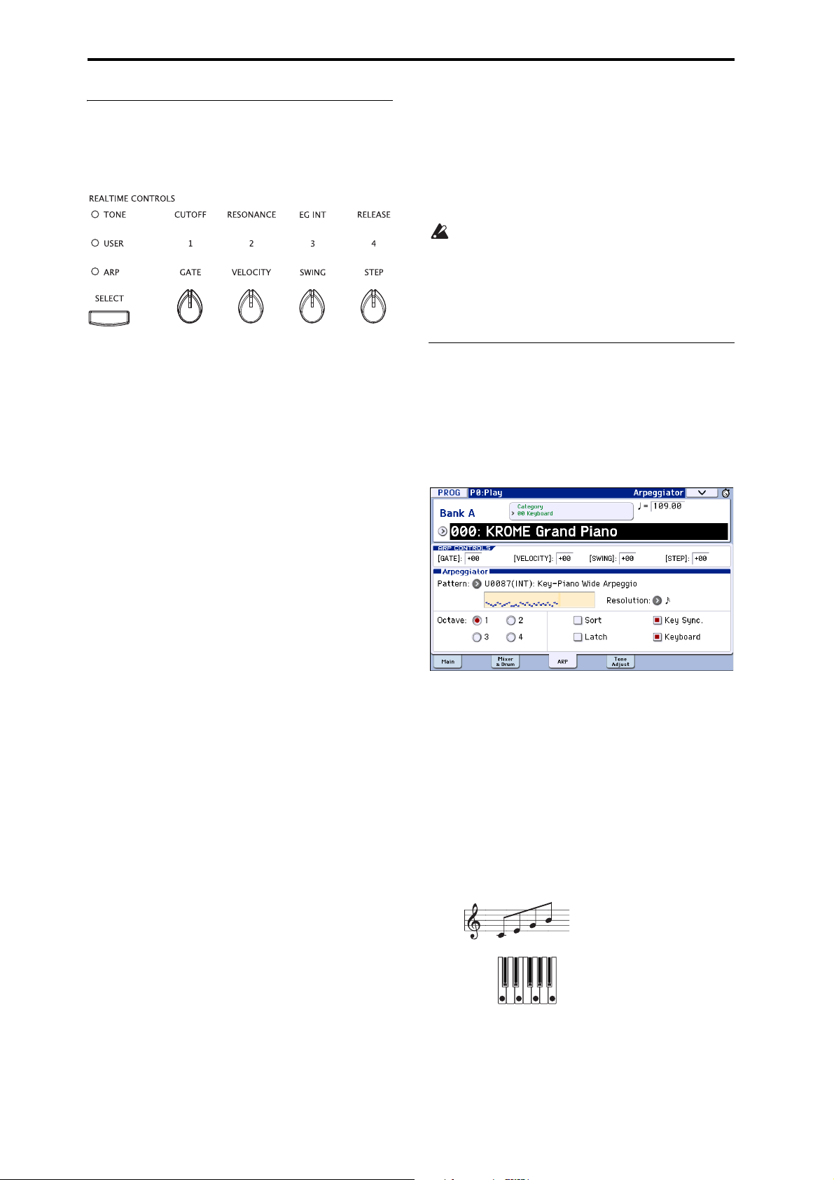
Arpeggiator function
Using knobs 1–4 to control the
arpeggiator
• You can control the arpeggiator by pressing the SELECT
button to select ARP and then turning knobs 1–4.
Adjusting the duration of the arpeggiated
notes: GATE
• Turn knob 1 to adjust the duration of the
arpeggiated notes.
Rotating the knob toward the left will shorten the
duration of the notes, and rotating it toward the
right will lengthen the duration of the notes. At the
center position (12 o’clock), the note length will be
as specified by the program parameter: Gate (Prog
P7: ARP/DT– ARP Setup page).
Note: The knob setting is saved when you write each
program.
Note: It is effective to use the SELECT button to select
TONE, and then adjust knob 4 (RELEASE).
Turning the knob toward the left will shorten the
pattern length (“Length”) by half. Turning the knob
toward the right will shorten the interval of the
arpeggiated notes (“Resolution”) by half. When the
knob is in the center position (12 o’clock), the pattern will be as specified by the parameters Length
and Resolution (Global P6: Arpeggio Pattern–
Setup page).
The preset arpeggio patterns P0-P4 can not change
the parameters SWING and Length.
Note: The state of the knobs is saved when you write
the program.
Note: Depending on the program that’s selected, using
knob 4 may not produce any effect.
Selecting an arpeggio pattern and
specifying its function
In the Prog P0: Play– Arpeggiator page you can select
an arpeggio pattern and specify how the arpeggiator
will function.
• In Prog P0: Play, press the ARP tab to access the
Prog P0: Play– Arpeggiator page.
Changing the dynamics of the arpeggiated
notes: VELOCITY
• Turn knob 2 to adjust the dynamics of the
arpeggiated notes.
Turning the knob toward the left will make the
notes softer, and turning it toward the right will
make the notes stronger. When the knob is in the
center position (12 o’clock), the value of the program parameter Velocity (Prog P7: ARP/DT– Arp
Setup page) will be used.
Note: The state of the knob is saved when you write
the program.
Note: It is effective to use the SELECT button to select
TONE, and then adjust knobs 1 (CUTOFF), 2
(RESONANCE), and 3 (EG INT).
Adding a shuffle feel to the arpeggio pattern:
SWING
• If you turn knob 3, the timing of the arpeggiated
notes on even-numbered beats will be shifted
forward or backward.
Turning the knob toward the left will speed up the
timing of the even-numbered beats. When the knob
is in the center position (12 o’clock), the timing will
be as specified by the program parameter Swing
(Global P6: Arpeggio Pattern- Setup page).
Selecting an arpeggio pattern
An arpeggio pattern can be selected from preset arpeggio
patterns P0–P4 and user arpeggio patterns U0000(INT)–
U1027(USER). The factory settings U0000(INT)–U0899(INT),
U0900(USER)–U1027(USER) contain a wide variety of
preloaded user arpeggio patterns.
Pattern
• Choose
buttons, and popup menu to select an arpeggio pattern.
User arpeggio patterns can also be selected by using
the numeric keys 0–9 to input the pattern number
and then pressing the ENTER button.
P0: UP
UP
, and use the VALUE dial, INC/DEC
Changing the number of steps in the
arpeggio pattern: STEP
• By turning knob 4 (STEP), you can change the
number of steps in the arpeggio pattern.
86
Page 91

Using the arpeggiator while you play Using the arpeggiator in Program mode
DOWN
ALT1
ALT2
RANDOM
Octave: 4
UP
ON, UP
Sort
OFF, UP
Sort
1324
P1: DOWN
P2: ALT1
P3: ALT2
P4: RANDOM
Sounding an arpeggio in the order of the
pitches in the chord you played
You can select whether the notes of the arpeggio will
be sounded in the order of the pitches in the chord you
played (regardless of the order in which you actually
played the notes), or in the order in which you played
the notes.
• Press the “Sort” check box in the display to make
this setting.
Checked: the arpeggio will play each note in the
order of its pitch, regardless of the order in which
you actually played the notes.
Unchecked: the arpeggio will trigger each note in
the order in which you actually played the notes.
Changing the note value of the arpeggiated
notes
The Resolution parameter lets you set the note value
of the arpeggiated notes, over a range from 3 – .
•Press Resolution, and use the VALUE dial, INC/
DEC buttons, or popup menu to select the desired
arpeggio note value.
Selecting the octave range where the
arpeggio is sounded
Use the “Octave” radio buttons to specify the range of
octaves where the arpeggio will play.
• Press an “Octave” radio button to make your
selection.
Setting the arpeggio to continue playing
even after you have taken your hand off the
keyboard
You can select whether the arpeggio will continue
playing when you take your hand off the keyboard, or
whether the arpeggio will stop.
• Press the “Latch” check box to make this setting.
Checked: The arpeggio will continue playing even
after you remove your hand from the keyboard.
Unchecked: The arpeggio will stop playing when
you remove your hand from the keyboard.
Synchronizing the arpeggiator to your
keyboard timing
You can specify whether the arpeggio will begin at the
moment you play the keyboard, or whether it will
always play in synchronization to the MIDI clock
tempo.
• Press the “Key Sync.” check box to make this
setting.
Checked: The arpeggio pattern will start from the
beginning when you press a key. This setting is suitable when you want the arpeggio to start from the
beginning of the measure as you are playing in realtime.
Unchecked: The arpeggiator will synchronize to the
MIDI clock timing.
Sounding both the arpeggio notes and the
notes you play
• Press the “Keyboard” check box to adjust this
setting.
Checked: The notes you play on the keyboard and
the notes played by the arpeggiator will both be
heard.
87
Page 92

Arpeggiator function
Unchecked: Only the arpeggiated notes will sound.
Changing the duration of the arpeggiated
notes
The P7: ARP/DT– ARP Setup Gate parameter specifies
the duration of the arpeggiated notes. With a setting of
000–100(%), the duration will always be the specified
gate time. Step is available if you’ve selected
U0000(INT)–U1027(USER) as the Pattern; the gate
value specified for each step will be used.
You can also control this by using the arpeggio control
(ARP) GATE knob (see page 86).
Specifying the arpeggio pattern’s velocity
and other settings
In P7: ARP/DT– ARP Setup, the Velocity parameter
specifies the velocity of the arpeggiated notes. If you
choose a value in the range of 001–127, that velocity
value will always be used. If you choose Key, the
velocity value of how you played the key will be used.
Step is available if “Pattern” is set to U0000(INT)–
U1027(USER); this causes the velocity value specified
for each step to be used.
“Swing” offsets the timing of arpeggiated notes that
are even-numbered (counting from the beginning).
“Velocity” and “Swing” can be controlled by knobs 2
and 3 respectively when SELECT is set to ARP.
Using the arpeggiator in Combination mode
In Combination mode the KROME provides dual
arpeggiators, allowing you to run two arpeggio
patterns simultaneously.
1. In Combination mode, select a combination (see
“Selecting Combinations” on page 43).
As you select various combinations, you’ll notice that
the ARP button LED will light up for some
combinations (see “Linking the arpeggiator to
programs or combinations” on page 91).
When you play the keyboard, the arpeggiator will
start. Even for other combinations, you can turn the
arpeggiator on by pressing the ARP button (the LED
will light up).
2. Listen to how the arpeggio can be modified as
described in the “Using knobs 1–4 to control the
arpeggiator” (above) and “Selecting an arpeggio
pattern and specifying its function” sections
(below).
The [ARP] switch, [TEMPO] knob, [TAP] switch or
each realtime control knob (when ARP is selected
using the [SELECT] switch) are enabled for both
arpeggiators A and B. Their state is saved when
the combination is written.
Selecting an arpeggio pattern and
adjusting settings
In the Combi P0: Play– Arpeggiator page you can
select an arpeggio pattern and specify how the
arpeggiator will function.
• In Combi P0: Play, press the ARP A tab or the ARP
B tab to select the Combi P0: Play– Arpeggiator A
or B page.
Timbre AssignArpeggiator Run
Specifying the zone where the arpeggiator
will function
In P7: ARP/DT– ARP Scan Zone you can specify the
range of notes (keys) and velocities where the
arpeggiator will function.
88
Select the arpeggiator(s) that will run
Use the Arpeggiator Run check boxes to specify the
arpeggiator(s) that you want to have running. The
arpeggiator(s) that are checked here will run when the
ARP button is on. However, the arpeggiator will only
play a timbre if the table next to the check boxes
assigns arpeggiator A or B to a timbre: T 1–16. You
change these settings in Combi P7: ARP/DT– ARP
Setup T01–08, T09–16 page Arpeggiator Assign (see
page 90).
Page 93
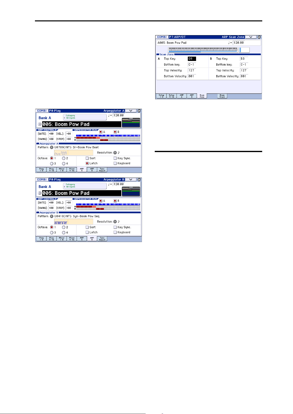
Using the arpeggiator while you play Arpeggiator settings in Combination and Sequencer modes
Arpeggiator-A, Arpeggiator-B
For each arpeggiator A and B, you can adjust settings
for Pattern (Select), Resolution, Octave, Sort, Latch,
Key Sync, and Keyboard (see page 86).
Checking the structure of a user arpeggio
pattern
Let’s see how the combination “A005: Boom Pow Pad”
(category: LeadSplits) is constructed.
• Select combination “A005: Boom Pow Pad”
(category: LeadSplits), and look at the Arpeggio
Play A page and Arpeggio Play B page.
• The drum programs of timbres 1–4 use the same
arpeggiator A pattern, but since the notes sounded
by each timbre are divided by key zone, each will
play only a portion of the arpeggiator pattern. Go to
the P0: Play–Program T01–08 page and try muting
each timbre 1–4 to hear the result. You can add
variety by using different combinations of timbres.
Arpeggiator settings in
• In “Timbre Assign” you’ll see that arpeggiator A is
assigned to timbres 1–5, and arpeggiator B is
assigned to timbres 6 and 7.
When you play the keyboard, the drum programs of
timbres 1–4 will be sounded by the arpeggio pattern
of arpeggiator A. (Timbre 5 is a dummy program
used to play timbres 1–4. See page 91.)
Arpeggiator B will sound the programs of timbres 6
and 7.
• If you uncheck Arpeggiator Run A or Arpeggiator
Run B, it will stop.
If you check it once again and play the keyboard,
that arpeggiator will begin running.
• When you access the Combi P7: ARP/DT– ARP
Scan Zone page, you’ll see that the B “Top Key”
and “Bottom Key” parameters are set so that
arpeggiator B will run only for the notes B3 and
below. Arpeggiator A is set to run for any key.
Combination and Sequencer
modes
In Combination and Sequencer modes, you can use use
two arpeggio patterns simultaneously, thanks to the
KROME’s dual arpeggiator functionality. The settings
in each of these modes are adjusted in a similar way.
The following example shows how to adjust settings in
Combination mode.
The dual arpeggiator functionality lets you do the
following things.
• Assign an arpeggiator for each timbre. Choose from
Off, (arpeggiator) A, or (arpeggiator) B. → step 5
• Independently specify whether A and B will
function.
• Select an arpeggio pattern and set parameters
independently for A and B.
• Make Scan Zone page settings so that you can use
keyboard range or playing velocity to switch
between normal playing and arpeggiated playing,
or to switch between arpeggiators A and B. → step
8
• Make settings for timbres that will be silent when
the arpeggiator is Off, and will sound only when
the arpeggiator is On. → step 10
→ step 6
→ step 7
89
Page 94
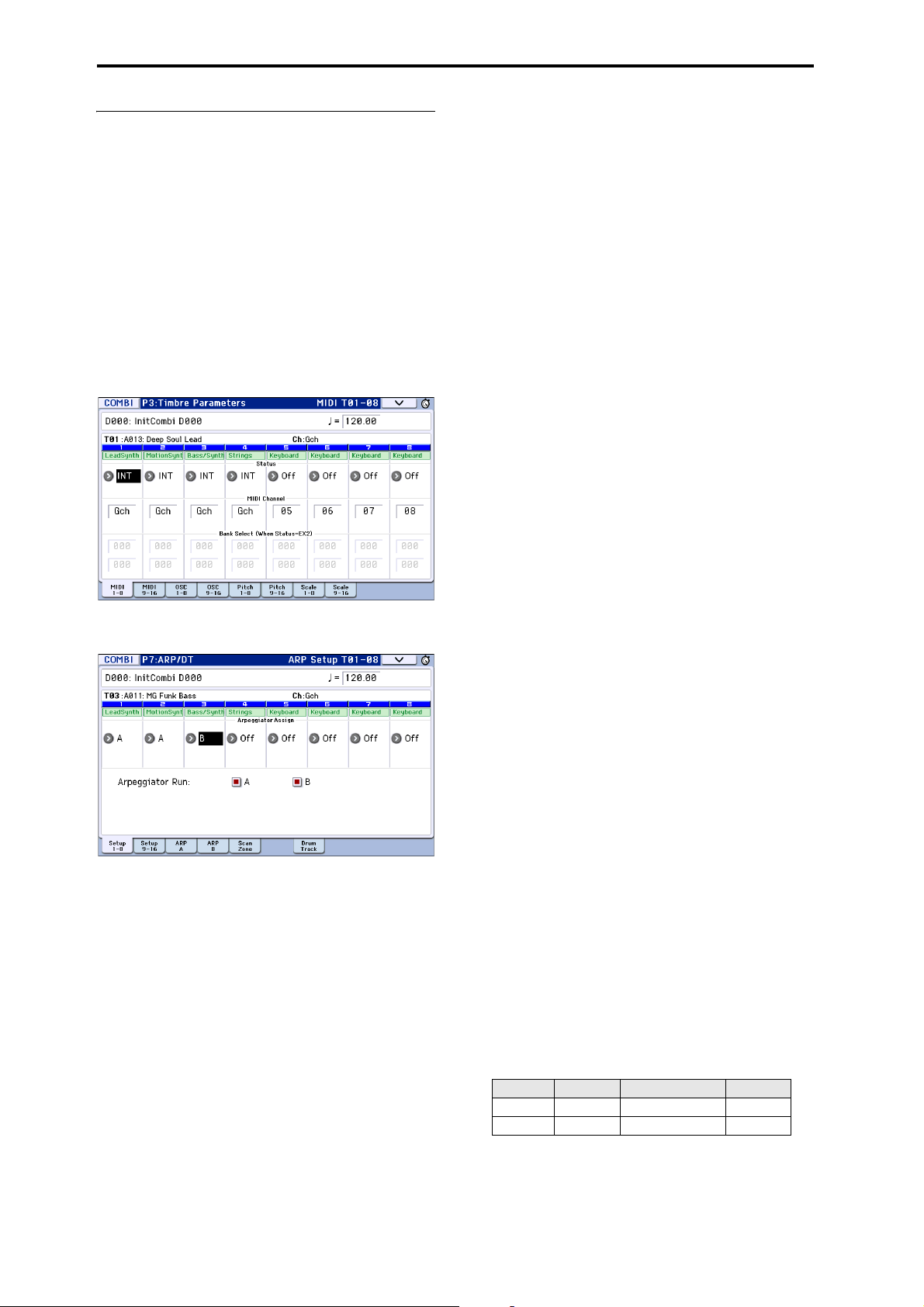
Arpeggiator function
Arpeggiator settings
1. Select Combi P0: Play– Program T01–08 page.
Select programs for the timbres that you wish to use.
For this example, select any desired program for
timbres 1–4.
2. Select Combi P3: Timbre Parameters, MIDI T01–08
page.
For the timbres that you will be using, set Status to
INT, and set MIDI Channel to Gch or to the global
MIDI channel (set in Global P1: MIDI Basic MIDI
Channel).
For this example, set timbres 1–4 to a Status of INT,
and timbres 5–8 to a Status of Off. Set the MIDI
Channel of timbres 1–4 to Gch.
7. On the Arpeggiator A and Arpeggiator B pages, set
the parameters for arpeggiators A and B.
The parameters for A and B are the same as for a
program (see page 86).
8. In the Scan Zone A/B page, specify the range in
which arpeggiators A and B will function.
The parameters for A and B are the same as for a
program.
You can use keyboard ranges or velocity ranges to use
one or both of the arpeggiators, or to switch between
arpeggiators A and B. By using the Combi P4: Zone/
Delay– Key Zone T01–08 – T09–16 page, and Vel Zone
T01–08 – T09–16 page to set keyboard and velocity
ranges in conjunction with each other, you can create
even more variations.
9. If you wish to save the edited combination
settings in internal memory, turn off memory
protect in Global mode, and write the combination
(see page 115 and page 117).
10. The “Status,” “MIDI Channel” and “Assign”
settings shown in the display of steps 2 and 3 can
be made so that certain timbres will sound only
when the arpeggiator is On, and will be silent
when the arpeggiator is Off.
3. Select Combi P7: ARP/DT– ARP Setup T01–08
page.
4. Set “ (Temp)” to specify the tempo.
This is the same as for a program. However, the tempo
is shared by both arpeggiators A and B.
5. Make “Arpeggiator Assign” settings.
Assign arpeggiator A or B to the desired timbres. Each
timbre will be played by the arpeggiator that has been
assigned to it.
6. Make “Arpeggiator Run” settings.
Check the arpeggiator(s) that you want to run. The
arpeggiator(s) checked here will run when the ARP
button is turned on.
With the settings shown in the display for steps 2 and
3, turning the ARP button on will cause arpeggiator A
to run for timbres 1 and 2, and arpeggiator B to run for
timbre 3. When the ARP button is turned off, timbres
1–4 will sound as a layer.
If all timbres Assign status are set to Off, or if
Arpeggiator Run A or B is unchecked, the arpeggiator
will not function.
90
Combination A001: Bossa Rose (SW1/2)
(Category: Keyboard)
Although this is a somewhat sophisticated editing
technique, we will describe the settings of one of the
preset combinations as an example.
When you play a specific region of the keyboard, this
combines settings that cause the arpeggiator to play an
arpeggio using different sounds than what's being
played by the keyboard, with other settings that cause
the arpeggiator sounds to remain completely unplayed
when the arpeggiator is off.
Before you play, make sure that the global MIDI
channel (Global P1: MIDI Basic MIDI Channel) is set
to 01.
Select combination A001: Bossa Rose (SW1/2), turn the
ARP button on, and play.
• Arpeggiator A is assigned to timbre 2 and 16. When
you play the keyboard, the bass riff arpeggio
pattern will sound the timbre 2 program.
•The A
• Arpeggiator A is also assigned to timbre 16, but this
• If the arpeggiator is off, playing the keyboard will
Bottom Key and Top Key (Combi P7: ARP/
DT– ARP Scan Zone page) are set so that
arpeggiator A will function only for notes B3 and
lower.
is so that the timbre 2 program will sound only
when the arpeggiator is on.
Notice the timbre settings for timbre 2 and 16.
Timbre Status MIDI Channel Assign
2INT02 A
16 Off Gch A
sound the timbre(s) that are set to Gch or to the
global MIDI channel (in this case, 01). Since the
MIDI Channel of timbre 2 is set to 02, it will not
sound. Timbre 16 is set to Gch, but since “Status” is
Off it will not sound.
Page 95
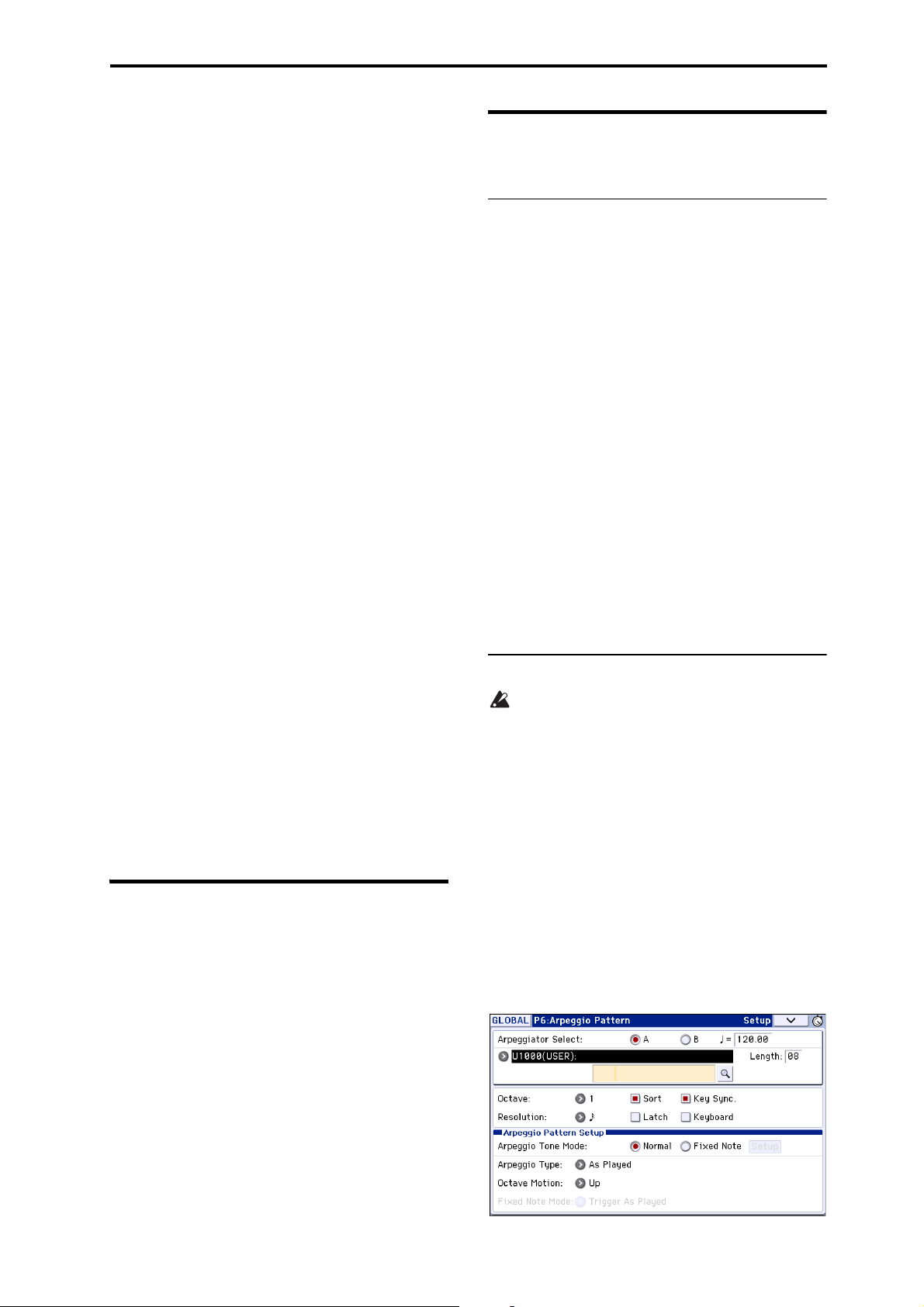
Using the arpeggiator while you play Linking the arpeggiator to programs or combinations
• Notes from any MIDI channel that is assigned to a
timbre will trigger the arpeggiator. In this case,
these will be MIDI Channel 02 and Gch (global
MIDI channel). When the arpeggiator is on, playing
the keyboard will trigger arpeggiator A, which is
assigned to timbre 16 (Gch). Timbre 2 will be
sounded by arpeggiator A. Since the Status of
timbre 16 is Off, it will not sound.
•Since the Status of timbre 16 is Off, it will not
sound, regardless of whether the arpeggiator is on
or off. It is a dummy timbre that causes timbre 2 to
sound only when the arpeggiator is on.
Combination A005: Boom Pow Pad
(Category: Synth)
Before you play, make sure that the global MIDI
channel (Global P1: MIDI Basic MIDI Channel) is set
to 01.
Select combination A005: Boom Pow Pad, turn the ARP
button on, and play.
• Arpeggiator A is assigned to timbres 1–5, and
arpeggiator B is assigned to timbres 6 and 7. When
you press any note of the entire keyboard, the drum
programs of timbres 1–4 will be sounded by the
arpeggio pattern of arpeggiator A. When you play
the B3 or a lower note on the keyboard, the synth
programs of timbres 6 and 7 will be sounded by the
backing arpeggio pattern.
• The arpeggiator A parameters “Bottom Key” and
“Top Key” (Combi P7: ARP/DT– ARP Scan Zone
page) are set so that arpeggiator A will run for the
entire keyboard.
•The B Bottom Key and Top K ey (Combi P7: ARP/
DT– ARP Scan Zone page) are set so that
arpeggiators B will function only for the note B3
and below.
• Arpeggiator A is assigned to timbre 5 as well, but
this setting is so that the timbre 1 to 4 program will
sound only when the arpeggiator is on. Refer to the
preceding section “Combination Bossa Rose (SW1/
2).”
Linking the arpeggiator to programs or combinations
You can specify whether the arpeggiator settings
written to a program or combination will be recalled
when you switch programs or combinations, or
whether the current arpeggiator settings will be
maintained.
With the factory settings, the former is selected. Use
the latter when you want to keep the same arpeggio
pattern running, and change only the program sound.
This setting is made in “Load ARP when changing”
(Global P0: Basic Setup, Basic page). (See page 110)
Creating a user arpeggio pattern
About user arpeggio patterns
The patterns that can be selected on the KROME’s
arpeggiator are called “arpeggio patterns.” There are
two types of arpeggio patterns: preset arpeggio
patterns and user arpeggio patterns.
Preset arpeggio patterns:
There are five patterns; UP, DOWN, ALT1, ALT2, and
RANDOM.
The functionality of these patterns is fixed, and cannot
be edited.
User arpeggio patterns:
There are 1028 patterns - U0000(INT)–U1027(USER) which can develop chords or phrases in a wide variety
of ways, based on the pitches that you play on the
keyboard or the timing with which you play them.
In Global P6: Arpeggio Pattern, Setup you can modify
these user arpeggio patterns, or create a new user
arpeggio pattern from an initialized condition. Edited
user arpeggio patterns can be written to internal
memory areas U0000(INT)–U1027(USER) (see
page 221 of the Parameter Guide).
In Media mode, you can also save user arpeggio
patterns to media.
Editing a user arpeggio pattern
If you want to edit a user arpeggio pattern, you
must first make sure that memory protect is
unchecked. (See page 197 of the Parameter Guide)
If you enter this mode from the Program mode, your
editing will apply to the arpeggio pattern specified for
the selected program.
1. In Program mode, select a program which uses the
arpeggio pattern you wish to edit, or a program
that you wish to use as a basis for editing the
arpeggio pattern.
2. Press the ARP button to turn the arpeggiator on
(the button will light up).
Even if you entered Global mode from a program in
which the arpeggiator was turned off, you can use the
ARP button to turn it on.
3. Select the Global P6: Arpeggio Pattern– Setup
page (see page 211 of the Parameter Guide).
91
Page 96

Arpeggiator function
Overview
Resolution
Tone Input
Touch Grid
Parameter
View
Zoom Scroll
T
4. “Arpeggiator Select” will automatically be set to A
when you navigate to this page from Program
mode.
5. In “Pattern,” select the arpeggio pattern that you
wish to edit.
For this example, select an empty user arpeggio
pattern.
If a blank pattern is selected, playing the keyboard
will not start an arpeggio. Although preset
arpeggio patterns P0–P4 can be selected, they
cannot be edited.
When you edit a user arpeggio pattern, the
changes will have an effect anytime that this
pattern is used in Program, Combination, or Song.
6. In “Length,” specify the length of the pattern.
After the pattern has played for the length specified, it
will return to the beginning. This setting can also be
changed during or after editing. For this example, set it
to 08.
Set knob 4 (STEP) to the center position (12
o’clock) so that the values of the “Length” and
“Resolution” parameters (Global P6: Arpeggio
Pattern- Setup page) will be used.
Note: For the preload arpeggio patterns U0000(INT)–
U0899(INT), simply changing the “Length” can
significantly change the character of the pattern. Try
changing the length and listening to the result. (See
“Length (Pattern Length)” on page 211 of the
Parameter Guide.)
7. Make settings for the “ (Tempo),” “Resolution,”
“Octave,” “Sort,” “Latch,” “Key Sync.,” and
“Keyboard” parameters.
These are program parameters, but they can be set
from here as well.
If after accessing this page from Program mode,
you modify these parameters and wish to keep
your changes, return to Program mode and write
the program. These parameters are not saved by
“Write Arpeggio Pattern.”
For this example, make the settings shown display step
3.
8. In Arpeggio Pattern Setup, specify how the
arpeggio will be developed.
9. Press the button to select Edit dialog.
You can also select the step by pressing the Step line
in the parameter view at the bottom. You can also
edit by dragging in the parameter view.
Press the button to the left of the parameter view to
switch between Pitch (Pitch Offset) → Gate (Gate)
→ Vel. (Velocity) → Flam (Flam).
• To ne : Each step can sound a chord of up to 12 tones
(Tone N o . 00–11). By touching and dragging the
overview on the right part of the screen or by using
the zoom scroll buttons above it, select the location
for entering tones in the zoom view below. Press
the touch grid to enter tones.
When Step is selected, you can also enter tones by
using the numeric keys 0–9 and the “–” and “.” buttons.
Note: The To ne No. corresponds to the numeric keys
0–9 and the “–” and “.” buttons as shown below. Each
time you press a numeric key 0–9 or a “–” or “.” button,
the corresponding tone will turn on or off. The
horizontal lines of the grid in the center of the display
correspond to tones.
Tone00–09: 0–9 buttons
one No.
Length: 8
Tone10: – button
Tone11: . button
05
Step No.
01
Entering tones
Alternate: Set or reset the tone.
Pen (set only): Set the tone.
Erase (reset only): Reset the tone.
Tool: Opens the tool tablet. The tool tablet lets you
use various commands in a region you’ve specified in
the overview, or to copy and paste (see “Tool Tablet”
on page 214 of the Parameter Guide).
Creating an example pattern
A pattern consists of Steps and Tones.
• Step: Each user arpeggio pattern has up to 48 steps.
Starting with the first step, the arpeggiator will play
notes at intervals of the note value specified by
Resolution. The vertical lines of the grid indicate
the steps.
Use Step to select the step; then specify Pitch Off-
set, Gate, Velocity and Flam for each step.
92
1. Press the alternate button.
2. Enter tones in the touch grid as shown in the
illustration below.
Page 97

Using the arpeggiator while you play Creating a user arpeggio pattern
3. When you play the keyboard as shown in the
illustration, the arpeggiator will begin playing.
Tone 0 corresponds to the pitch of the lowest key of
chord you play on the keyboard. (If Sort is unchecked,
it will correspond to the pitch of the first note you
play.)
4. For steps 01–08, make settings for “Pitch Offset,”
“Gate,” “Velocity,” and “Flam.”
Pitch Offset: This offsets the pitch of the arpeggio note
in semitones up or down. You can input the same tone
for each step, and change the Pitch Offset value for
each to create a melody using a single tone. (See
“Melody pattern”)
Gate: Specifies the length of the arpeggio note for each
step. With a setting of Legato, the note will continue
sounding either until the next note of the same tone or
until the end of the pattern. With a setting of Off, the
note will not sound.
Velocity: This specifies the strength of the note. With a
setting of Key, the note will sound at the strength of
how it was actually played.
The Gate and Velocity settings you select here will
be valid if the Gate and Ve lo c i t y parameters
(Program P7: ARP/DT– ARP Setup page) of the
program selected in Program mode are set to Step.
If these parameters have a setting other than Step,
the Gate and Velocity that were specified for each
individual step will be ignored, and all notes of the
arpeggio will sound according to the settings in
Program P7: ARP/DT– ARP Setup page. Be sure to
verify the settings of the program.
Other examples of creating a user
arpeggio pattern
Melody pattern
1. Press the alternate button.
2. In the touch grid, set tone 0 for “Step” 01, 02, 03, 04,
05, 07, and 08 (i.e., all but 06).
3. Specify the pitch. Set the “Step” 02 “Pitch” to +10,
“Step” 05 “Pitch” to +12, and the “Step” 08 “Pitch”
to –2.
When editing Gate, Velocity, and Swing, use the
SELECT button to select ARP, and set knob 1
(GATE) and knob 2 (VELOCITY) to the center
position (12 o’clock).
5. To change the user arpeggio pattern name, use the
“Rename Arpeggio Pattern” menu command. (See
page 221 of the Parameter Guide)
6. If you wish to save the edited user arpeggio
pattern to internal memory, be sure to Write the
user arpeggio pattern. (See page 221 of the
Parameter Guide)
If you turn off the power without writing, the edited
contents will be lost.
7. If you wish to save the state of the program at the
same time, return to Program mode and write the
program. (See page 115)
4. Play a single key; the arpeggio will begin playing.
Chordal pattern
1. Press the alternate button.
2. In the touch grid, set tone 00 of “Step” 01.
3. In “Step” 03, 04, 06, and 07, set tones 00–04.
4. Select “Step” 01, and set “Gate” to Legato.
5. Select “Step” 06, and set “Gate” to Legato.
Note: To simulate the timing nuances of a strummed
guitar chord, select Flam. In Program mode, select an
acoustic guitar program, and choose the user arpeggio
pattern that you created here. In the Arpeg. Program
P7: ARP/DT– ARP Setup page, set Gate to Step.
93
Page 98

Arpeggiator function
Then return to the Global P6: Arpeggio Pattern– Setup
page. For odd-numbered steps, set Flam to a positive
(+) value. For even-numbered steps, set Flam to a
negative (–) value.
Drum pattern
You can use the arpeggiator to play a rhythm pattern
by using “Fixed Note” with a drum program.
1. In Program mode, select a drum kit program.
For this example, select the preset program A017: Jazz
Dry/Amb1 Kit (Category: Drums).
2. In Global P6: Arpeggio Pattern, select the Setup
page, and parameter settings.
Arpeggio Tone Mode: Set this to Fixed Note. This will
cause the tone to always sound at the specified pitch.
Fixed Note Mode: If you set this to Trigger All Tones,
playing a single note on the keyboard will sound all
tones.
If you set this to Tri g g e r As Played, the tones will be
sounded according to the notes you play on the
keyboard (see page 212 of the Parameter Guide).
Let’s input the following rhythm pattern.
4. For each “Tone,” specify “Fixed Note No.”
Use the Fixed Note Setup button to open the dialog
box. Here you can assign a different drumsample (note
number) of the drum kit to each fixed note.
For this example, set Ton e No. and Fixed Note No. as
follows.
Tone No. Fixed Note No.
00 C2 (kick)
01 F2 (snare)
02 F#3 (closed hi-hat)
03 A#3 (open hi-hat)
3. Select the Edit page.
The drumsample corresponding to each note number
will differ depending on the drum kit. It’s best to play
the keyboard to find the drum sound you want; then
hold down Fixed Note No. and play that note to enter
the desired note number.
5. Press the alternate button.
6. Enter the kick (Tone00).
In the touch grid, set tone 00 (C2) of Step 01 and 05.
7. Enter the snare (Tone01).
In the touch grid, set tone 01 (F2) of Step 03 and 07.
8. Enter the closed hi-hat (Tone02).
In the touch grid, set tone 02 (F#3) of Step 01, 02, 03, 05,
06, and 07.
9. Enter the open hi-hat (Tone03).
In the touch grid, set tone 03 (A#3) for Step 04.
10. If Fixed Note Mode is set to Trigger As Played,
playing a single note on the keyboard will cause
only the kick (Tone00) to play.
Playing two notes on the keyboard will cause only the
kick (Tone00) and snare (Tone01) to play. In this way,
the number of keys that you play will be played by the
same number of tones.
94
Page 99

Using the arpeggiator while you play Creating a user arpeggio pattern
11. Set the parameters for each step.
Use Ve l oc i t y etc. to add accents to the rhythm pattern.
The Gate and Velocity settings you select here will
be valid if the Gate and Ve lo c i t y parameters
(Program P7: ARP/DT– ARP Setup page) of the
program selected in Program mode are set to Step.
If these parameters have a setting other than Step,
the Gate and Velocity that were specified for each
individual step will be ignored, and the notes of
the arpeggio will be sounded according to the
settings of the Program P7: ARP/DT– ARP Setup
page. Check the settings of the program.
To set Gate or Velocity, select ARP with the
[SELECT] switch and set knob [1] (GATE) and
knob [2] (VELOCITY) to center position (12
o'clock).
Dual arpeggiator editing
Here we will use a combination as an example in our
explanation.
The same procedure applies when editing an arpeggio
pattern in Sequencer mode.
If you have entered this mode from the Combination
mode, the arpeggio pattern selected by the
combination will be affected by your editing.
1. In Combination mode, select a combination that
uses the arpeggio pattern you wish to edit.
For this example, select a combination where both
arpeggiators A and B are assigned.
2. Press the ARP button to turn on the arpeggiator
(the button will light up).
Even if the arpeggiator had been turned off when you
moved here, you can use the ARP button to turn it on.
However, if Arpeggiator Run A or B are not checked,
and if Arpeggiator Assign, is set to off, then the
arpeggiator will not function.
3. Select the Global P6: Arpeggio Pattern– Setup
page.
4. If you accessed this page from Combination mode,
use the “Arpeggio Select” A and B to select the
arpeggiator that you wish to edit.
If this is A, your editing will apply to the parameters
and user arpeggio pattern of arpeggiator A.
If this is B, your editing will apply to the parameters
and user arpeggio pattern of arpeggiator B.
5. Switch between arpeggiators A and B, and edit
their respective user arpeggio patterns.
If you wish to stop one of the arpeggiators, return to
Combination mode, and in Combination P0: Play–
Arpeggio A or the Arpeggio B page and uncheck the
Arpeggiator Run check box.
6. To modify the name of a user arpeggio pattern, use
the menu command “Rename Arpeggio Pattern.”
(See page 221 of the Parameter Guide)
7. If you wish to save the edited user arpeggio
pattern in internal memory, you must write the
user arpeggio pattern.
In this case, both user arpeggio patterns will be written
simultaneously. If you turn off the power without
writing, the edited contents will be lost (see page 221 of
the Parameter Guide).
8. If you wish to save the state of the combination at
the same time, return to Combination mode and
write the combination. (See page 115)
Note: When editing a user arpeggio pattern, pay
attention to the global MIDI channel, the channel of
each track, and the arpeggiator assignments, and make
sure that the arpeggiator you are hearing is the pattern
that you wish to edit.
95
Page 100

Arpeggiator function
Regarding arpeggiator synchronization
“Key Sync.” parameter
The timing of the arpeggiator notes depends on the
state of the arpeggiator Key Sync. check box.
If this box is checked, the arpeggiator will start
running at the first note-on that occurs after you’ve
taken your hands completely off the keyboard.
If this box is unchecked, the arpeggiator will run in
synchronization with the internal/external MIDI clock.
Below, we will explain how synchronization occurs
when the Key Sync. check box is not checked
(Synchronization with Song Start and with MIDI
realtime Start messages are excluded).
Synchronization between arpeggiators
A and B
In Combination and Sequencer modes, the two
arpeggiators can run simultaneously. In this case, if one
arpeggiator is already running, and you then run the
other arpeggiator (with “Key Sync.” unchecked), the
second arpeggiator will synchronize to the “ (Tempo)”
based on the first arpeggiator.
If Key Sync. is checked, arpeggiators A and B will run
independently, each at their own tempo.
Synchronization with the drum track
If you want the arpeggiator to synchronize to the drum
track pattern that’s currently playing, uncheck the Key
Sync. setting. In this case, the arpeggiator will
synchronize to the beat of the drum track pattern that’s
currently playing.
If you want the drum track pattern to synchronize to
the arpeggiator that’s currently running, turn on the
“Sync” setting (the Trigger parameter of the Drum
Track page of each mode).
Synchronization with Song Start
• If the arpeggiator is turned on (ARP button is on)
and is running, it will reset to the beginning of its
arpeggio pattern when a Song Start is received.
(This is unaffected by the Key Sync. setting.)
•In Sequencer mode when Key Sync. is unchecked
and the ARP button is on, if you start the
arpeggiator by pressing a key during the pre-count
before recording begins, the arpeggiator will start
its pattern as soon as recording begins, and will be
recorded.
Synchronization with external sequencer
playback
If “ (Tempo)” is EXT (i.e., if Global P1: MIDI MIDI
Clock is External MIDI or External USB) in Program,
Combination, or Sequencer modes, the arpeggiator
will synchronize to the MIDI timing Clock and Start
messages received from a connected MIDI device.
Note: Synchronization will occur in the same way if
MIDI timing Clock is Auto and MIDI realtime clock
messages are being received from a connected MIDI
device.
Synchronization with external MIDI timing clock
The arpeggiator will synchronize to the “ (Tempo)”
timing of the external MIDI timing clock.
Synchronization with MIDI realtime Start messages
If the arpeggiator is turned on and running, an
incoming MIDI realtime Start message will reset the
arpeggiator to the beginning of its pattern (This is
unaffected by the Key Sync. setting).
Synchronization between the arpeggiator
and sequencer in Sequencer mode
If song playback is stopped
• The arpeggiator will synchronize to the “ (Tempo)”
based on the internal MIDI clock timing.
• If an RPPR pattern is playing in Sequencer mode,
the arpeggiator will synchronize to the beat based
on that pattern.
If you want the RPPR pattern playback to synchronize
to the arpeggiator that’s currently running, set “Sync”
to SEQ (SEQ P10: Pattern/RPPR– RPPR Setup page).
Pattern playback will synchronize to the “ (Tempo)”
timing of the arpeggiator.
While playing back or recording a song
• The arpeggiator will synchronize to the beat based
on the timing of the song.
96
 Loading...