

Page 1

INSTALLATION MANUAL
PC-201
Paper Feed Cabinet
for Product Code 4036
NOTES
• Before installing, be sure to unplug the power cord of the machine.
• Keep all packing materials out of the reach of children.
4348-7782-01 Printed in Japan
Page 2
PC-201
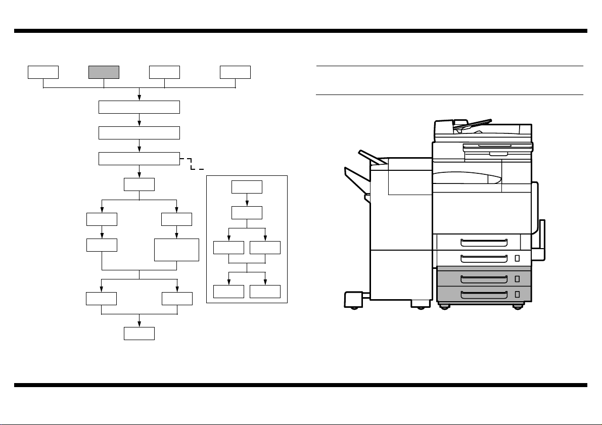
■ Outline of Installation Procedures for 4036 System
PC-101 PC-201 DK-501
Dehumidifier Heater 1C
Copier/Printer Machine
Electron System Options
FS-501
JS-601
DF-601
PC-401
✱ Electron System Options
AD-501
FS-601
PK-501/PK-4/
PK131
OC-501
WT-501
EM-301
HD-501
EK-501 VI-501
D-103DT-105
When installing the machine and associated options as a system, follow the order shown
on the left.
NOTE
For the detailed installation procedures for each option, follow the instructions given
in the corresponding Installation Manual and perform the procedures correctly.
4348U110AA
– 1 –
Page 3
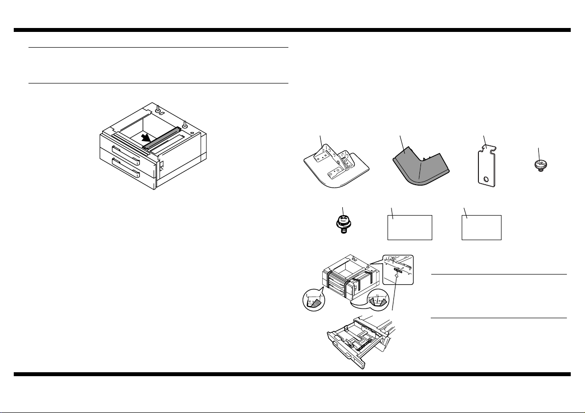
■ Unpacking the Paper Feed Cabinet
NOTE
When removing the Paper Feed Cabinet from its shipping carton, do not hold onto
the reinforcement bracket (indicated by the arrow in the illustration below) (as a
personal injury or a deformed frame could result).
PC-201
1. Check that the following accessories are available in the box.
1 Fixing Leg...............................................................................................4
2 Fixing Leg Cover ....................................................................................4
3 Fixing Bracket ........................................................................................4
4 Shoulder Screw ......................................................................................4
5 Screw (9646-0408)...............................................................................12
6 Paper Size Label ....................................................................................1
7 Installation Manual (this manual) ...........................................................1
4348U004AA
– 2 –
1 2
4348U020AB
5
9646040813
.
4348U119AA
4348U118AA
3
4348U099AB
4658U021AA 4658U022AA
67
2. Remove the protective tape from the inside
of the drawer.
NOTE
Do not peel off the tape that fixes the Paper
Feed Cabinet hookup harness in position
until the machine is attached to the Paper
Hookup Harness
Feed Cabinet.
4
Page 4

PC-201
■ Attaching the machine to the Paper Feed Cabinet
1. Remove the Drawer Rear Cover from the
machine (four screws).
NOTE
Be sure to remove the Drawer Rear Cover
before attempting to attach the machine to
the Paper Feed Cabinet.
4348U121AA
2. Holding onto the transportation handles at
the front and rear of the machine, place the
machine onto the Paper Feed Cabinet.
When placing the machine, use the
positioning pins in the rear of the Paper Feed
Cabinet to align the machine correctly with
the cabinet.
4348U117AA
4348U005AA
* Fit the rear side first.
NOTE
When attaching the machine, use care not
to apply load to the paper take-up section
of the machine.
3. Peel off the tape that fixes the Paper Feed
Cabinet hookup harness in position.
4. Connect the two connectors of the Paper
Feed Cabinet hookup harness to the
machine.
5. Using the Fixing Brackets and Shoulder
Screws furnished with the Paper Feed
Cabinet, secure the machine to the Paper
Feed Cabinet (at two places in the rear).
4348U114AA
6. Reinstall the Lower Rear Cover which has
been removed in step 1 (four screws).
4348U116AB
7. Slide out the 3rd Drawer.
8. Using the Fixing Brackets and Shoulder
Screws furnished with the Paper Feed
Cabinet, secure the machine to the Paper
Feed Cabinet (at two places at the front).
4348U051AA
■ Installing the Fixing Leg and Fixing Leg covers
1. Move the machine and Paper Feed Cabinet
to the installation site. Then, adjust the two
adjusters at the front to let the Paper Feed
Cabinet sit on the floor.
4348U113AA
4348U115AA
– 3 –
Page 5

PC-201
①
②
③
③
②
4348U023AD
4348U100AC 4348U102AB
①
①
②
③
③
②
4348U024AD
4348U101AC 4348U102AB
①
2. Install the Fixing Legs at two locations in the
front shown in the illustration (six screws
furnished with the Paper Feed Cabinet).
3. Install the Fixing Leg Covers at two locations
in the front shown in the illustration
(2 Pieces).
NOTES
• Insert the Fixing Leg Covers in the direction shown by arrow until they click into
position.
• Insert the Protruded Portions of the cover
shown by the arrows into the Fixing Leg.
4. Install the Fixing Legs at two locations in the
rear shown in the illustration. (six screws
furnished with the Paper Feed Cabinet).
5. Install the Fixing Leg Covers at two locations
in the rear shown in the illustration
(2 Pieces).
NOTES
• Insert the Fixing Leg Covers in the direction shown by arrow until they click into
position.
• Insert the Protruded Portions of the cover
shown by the arrows into the Fixing Leg.
■ Loading Paper
1. Slide out the 3rd and 4th Drawer.
4348U048AA
2. Load the paper stack so that it rests below
the tab fitted to the Edge Guide.
4348U095AA
4348U091AA
NOTES
• Make sure that the top level of the paper stack does not exceed the
level indicator.
• Slide the Edge Guide tightly up against the edge of the paper stack so that there is
no gap between them.
• With the Trailing Edge Stop, fit its locking tab properly into the slit at the correct
paper size position.
• Correct any curl in the paper before loading.
▼
(MAX) paper
– 4 –
Page 6

PC-201
■ Installing the Ornamental Cover ■ Checking and Adjusting the Paper Reference Position
1. Install the Ornamental Cover attached to the
machine (two screws).
1. Plug the power cord into the power outlet
and turn on the machine.
2. Display the Tech. Rep. Mode screen.
(For details of how to display the Tech. Rep.
Mode screen, see the Service Manual.)
4348U049AA
4348U052AA
2. Slide the drawer back in.
3. Affix the Paper Size Label furnished with the
Paper Feed Cabinet to the location shown in
the illustration. (The size label is similarly put
on the 4th.)
– 5 –
4036P031CA
4036P036CA
4348P023CA
4348P024CA
3. Touch “Machine Adjust.”
4. Touch “PRT Area.”
5. Touch “Left Margin.”
6. Touch “3rd” and then press the Start key.
A test print will be produced.
Page 7

PC-201
C4658U028AA
4348U008AB
A
Paper Exit
Direction
7. Measure width A from the edge of the paper
to the pattern printed on the test print and
check that it falls within the specified range.
Specifications: 3.0 mm ± 1.0 mm
• Adjusting the Paper Reference Position
If the measured width A falls outside the
specified range, enter the correction value
using the or key.
8. Produce another test print and check to see
if width A falls within the specified range.
* Do the same procedure for the 4th that for
3th drawer.
* If the use of the or key does not
allow the measurement to fall within the
specified range, perform the following steps.
9. Slide out the drawer and unload paper from
it.
10. Loosen the three screws at the center of the
Paper Lifting Plate.
4348U009AA
11. Watching the graduations provided in the
drawer, move the Edge Guide in the rear.
• If width A is greater than the specified value,
move the Edge Guide toward the front.
• If width A is smaller than the specified value,
move the Edge Guide toward the rear.
12. Load paper and let the machine produce
another test print. Then, check width A.
* Make the adjustment until width A falls within
the specified range.
13. Tighten the screws which has been loosened
in step 10.
14. Touch “OK.”
15. Touch “Fin. Time” on the Tech. Rep. Mode
screen.
– 6 –
 Loading...