

Page 1
KIP 9000 User Guide
Version A0
Page 2

Thank you for purchasing the KIP 9000.
This USER’S MANUAL contains functional and operational explanations for the KIP 9000. Please
read this USER’S MANUAL carefully before using the Printer. Please keep this USER’S MANUAL
for future reference.
When this machine is installed in USA
FCC ID : VP8-K115
This equipment satisfies the requirements in Part 15 of FCC Rules for a Classic A computing
device.
Operation is subject to the following two conditions:
(1) This device may not cause harmful interference.
(2) This device must accept any interference received, including interference that may cause
undesired operation.
In order to comply with FCC radio-frequency radiation exposure guidelines for an uncontrolled
exposure, this device and its antenna must not be co-located or operating in conjunction with any
other antenna or transmitter.
FCC 15.105(a)
NOTE: This equipment has been tested and found to comply with the limits for a Class A digital
device, pursuant to part 15 of the FCC Rules. These limits are designed to provide reasonable
protection against harmful interference when the equipment is operated in a commercial
environment. This equipment generates, uses, and can radiate radio frequency energy and, if not
installed and used in accordance with the instruction manual, may cause harmful interference to
radio communications. Operation of this equipment in a residential area is likely to cause harmful
interference in which case the user will be required to correct the interference at his own expense.
FCC 15.21
Changes or modifications not expressly approved by the party responsible for compliance could
void the user’s authority to operate the equipment.
When this machine is installed in Canada
IC Company No. & UPN No. : 7391A-K115
Operation is subject to the following two conditions: (1) this device may not cause interference, and
(2) this device must accept any interference, including interference that may cause undesired
operation of the device.
When this machine is installed in Europe
This equipment satisfies the requirements in Pub.22 of CISPR Rules for a Classic B computing
device. Operation of this equipment in a residential area may cause unacceptable interference to
radio and TV reception requiring the operator to take whatever steps are necessary to correct the
interference.
Do not install this machine around electronic equipment or precision instruments. Other
devices may be effected by electrical noise during operation.
If Machine is installed near other electronic equipment, such as a TV or a radio, interference
to said equipment, such as noise or flickering, may occur. Use a separate power line and
install the PRINTER as far as possible from said equipment.
(1)
Page 3
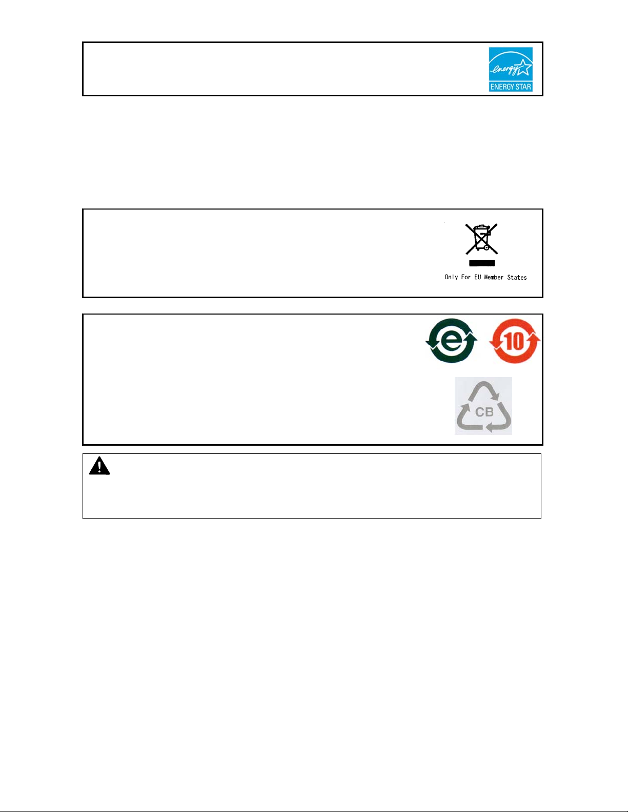
As an ENERGY STAR ® Partner, Katsuragawa Electric Co., Ltd. has determined
that this product meets the
The International
promotes energy saving through the penetration of energy efficient computers and other office
equipment. The program backs the development and dissemination of products with functions that
effectively reduce energy consumption. It is an open system in which business proprietors can
participate voluntarily. The targeted products are office equipment such as computers, monitors,
printers, facsimiles, copiers, scanners, and multifunction devices. Their standards and logos are
uniform among participating nations.
The symbol shown indicates that this product conforms to Directive
2002/96/EC of the European Parliament and the council of 27 January
2003 on waste electrical and electronic equipment (WEEE) and does not
apply to countries outside of EU.
The symbol shown indicates that this product conforms to
SJ/T11364-2006 of People’s Republic of China Electronic
Industry Standard and does not apply to countries outside of
People’s Republic of China.
The symbol shown indicates that this product conforms to GB
18455-2001 11364-2006 of National Standard of the People’s
Republic of China and does not apply to countries outside of
People’s Republic of China.
NOTE
KIP 9000 will not function if no optional device is connected.
Please ask the Service Personnel for the optional device.
ENERGY STAR ® Office Equipment Program is an international program that
ENERGY STAR ® guidelines for energy efficiency.
(2)
Page 4
The following warnings are very important in order to safely use this product.
These notes are very important in preventing danger to the operator or operation of the printer.
The following symbols are found throughout the USER’S Manual and have the following meaning:
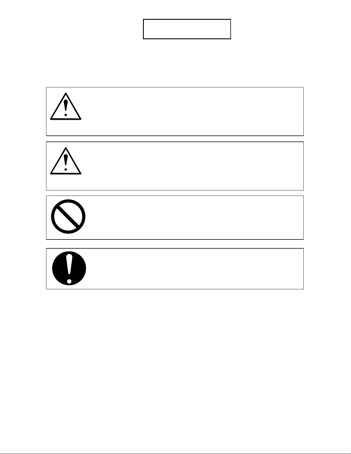
WARNING
This WARNING mark means that there is a possibility of death or serious
injury if you ignore or do not follow the said instruction.
CAUTION
This CAUTION mark means that there is a possibility of injury or physical
damage if you ignore or do not follow the said instruction.
When marked with this symbol, “DO NOT ATTEMPT”
When marked with this symbol, “pay close attention to”
Safety Warning
(3)
Page 5
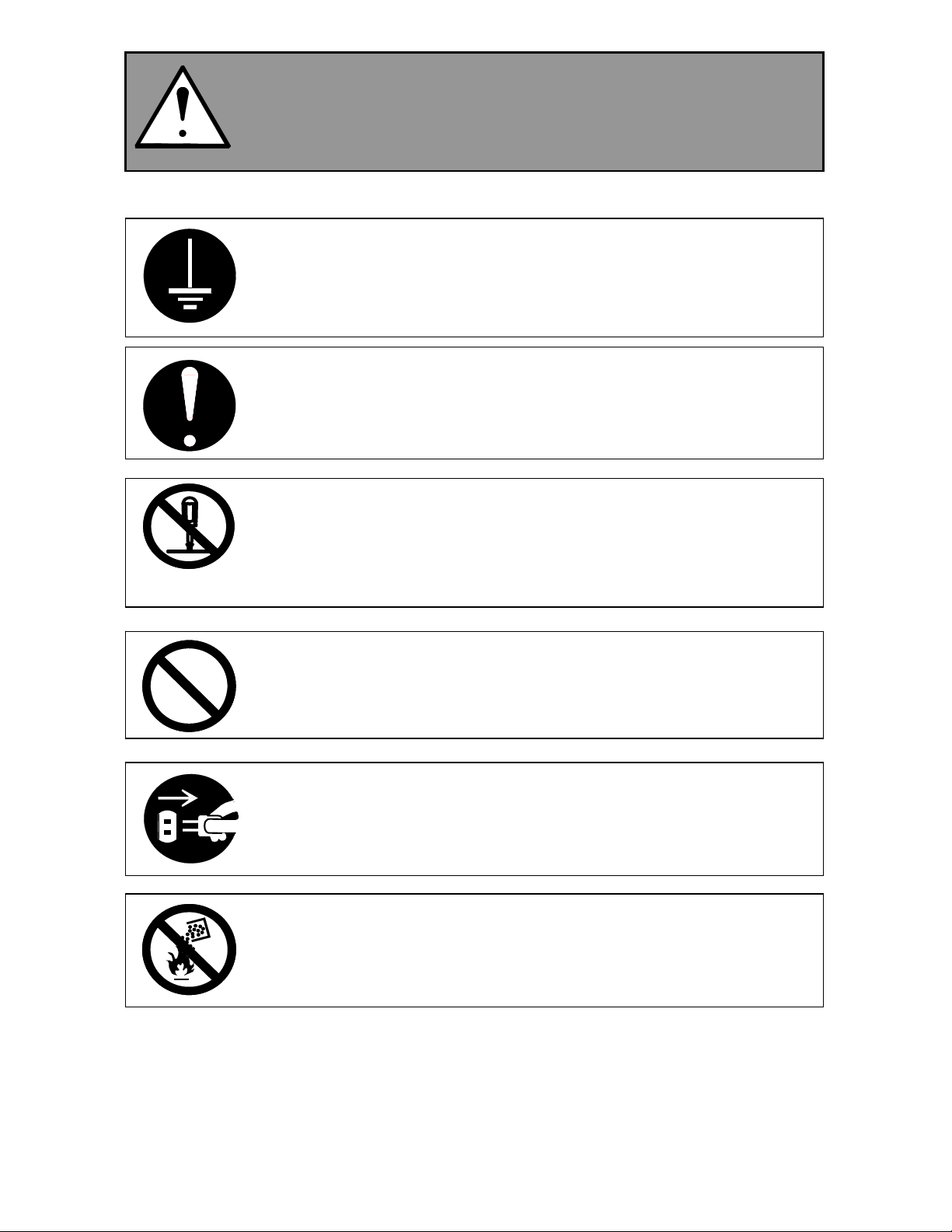
WARNING
Ground the product with a correct ground source or you may be electrically
shocked.
1. Connected outlet must satisfy the following condition.
U.S.A. / Europe : 220 - 240V (+6% / -10%), more than 16A, 50/60Hz
2. Use a circuit with an exclusive breaker.
3. Install the machine as close to the wall outlet as possible.
4. If you wish to move the printer, please contact to your service personnel.
1. Do not remove the screw and do not open the cover if not instructed to do
so in this User’s Manual. If you ignore this warning, you may be burnt or
receive an electric shock due to a hot item or electrically charged part
inside of the printer.
2. Do not disassemble or tamper with the printer. It may result in a fire or
electrical shock.
1. Do not plug in the printer into a multi-wire connector in which some other
equipment is plugged into. It may cause a fire due to outlet overheating.
2. Do not damage the Power Cord by stepping on or placing something heavy
items on it. If the Power Cord is damaged, it may cause a fire or you may
receive an electric shock. REPLACE THE CORD IF DAMAGED.
1. Do not PUT a flower vase, a flowerpot or any water-filled item on the
product. Spilt water could cause a fire or an electric shock.
2. If the product generates an abnormal smell or noise, turn it off and unplug it
from the wall outlet immediately.
Do not throw the toner into a fire or other sources of heat, as it can explode.
(4)
Page 6
CAUTION
Do not install the machine in a humidified room or a dusty room.
Also, do not install the machine on an unstable floor as injuries may occur.
1. Unplug the printer before you move it. The power cord may be damaged
and it may result in a fire or electric shock.
2. If you do not use the printer for a long duration (holidays, company
shutdown) turn off and unplug the printer from the outlet for safety.
Do not pull the cord when you unplug the printer as you may damage the
Power Cord. Make sure to unplug the plug from the plug case.
There are hot items inside of the machine. Take great care not to touch these
items when you remove mis-fed media.
Ventilate the room well if you print in a small area.
(5)
Page 7

TABLE OF CONTENTS
Chapter 1 Before Use
Page
1. 1 Installation Requirements 1- 2
1. 2 Originals Prohibited from Duplication 1- 3
1. 3 Features 1- 4
1. 4 Specifications 1- 5
1. 5 Appearance 1- 7
1. 5. 1 Front view 1- 7
1. 5. 2 Right side view 1- 8
1. 5. 3 Rear view 1- 9
1. 5. 4 Operation Panel 1-11
1. 5. 5 Media Indicators 1-13
1. 5. 6 “in use” Indicators 1-14
Chapter 2 Basic Operations
Page
2. 1 Turning on the KIP 9000 2- 2
2. 2 Turning off the KIP 9000 2- 3
2. 3 Setting the Roll Media into Roll Deck 2- 4
2. 3. 1 Roll 1, 2 & 3 2- 5
2. 3. 2 Roll 4 2-11
2. 4 Setting Cut Sheet Media to Bypass Feeder 2-13
2. 4. 1 Multi-feeding of cut sheet media 2-14
2. 4. 2 Singular feeding of cut sheet media 2-15
2. 5 Replacing the Toner Cartridge 2-17
2. 6 Dehumidifying the Roll Media 2-21
2. 7 Initial Cut (Straighten the leading edge of roll media) 2-23
2. 8 User Modes 2-25
2. 8. 1 User Mode 1 (Test Print) 2-26
2. 8. 2 User Mode 2 (Calendar setting) 2-28
2. 8. 3 User Mode 3 (Warm Sleep Mode ON / OFF & timer setting) 2-33
2. 8. 4 User Mode 4 (Cold Sleep Mode timer setting) 2-37
2. 8. 5 User Mode 5 (Automatic paper cut at power ON) 2-40
2. 8. 6 User Mode 6 (Transfer Support LED ON/OFF [Film]) 2-43
2. 8. 7 User Mode 7 (Alarm ON / OFF) 2-46
2. 8. 8 User Mode 8 (Choice of Standard / Special Print Mode [Plain paper]) 2-49
2. 8. 9 User Mode 9 (Choice of Standard / Special Print Mode [Tracing paper]) 2-53
2. 8.10 User Mode A (Choice of Standard / Special Print Mode [Film]) 2-56
2. 8.11 User Mode B (Selection of Image Enhancement Mode) 2-59
2. 8.12 User Mode C (Print on TE margin area) 2-62
2. 8.13 User Mode D (Error check level for E-26 error) 2-66
2. 8.14 User Mode E (Error check level for E-28 error) 2-69
2. 8.15 User Mode F0 to Fb (Fold settings applied when Bay Folder is connected) 2-72
(6)
Page 8

Chapter 3 Error Corrections and Maintenanc e
Page
3. 1 Media Mis-feed Errors 3- 2
3. 1. 1 Mis-feed in Roll Decks (J-01, J-02, J-03 & J-04) 3- 3
3. 1. 2 Mis-feed in the Bypass Feeder (J-05) 3- 6
3. 1. 3 Mis-feed between Cutter and Drum (J-11) 3- 7
3. 1. 4 Mis-feed on Internal Transportation Unit (J-12) and Fuser Entrance (J-13) 3-11
3. 1. 5 Mis-feed in Fuser Unit (J-14) 3-18
3. 1. 6 Mis-feed in Folder (J-21) 3-25
3. 1. 7 Mis-feed in Auto Stacker (J-22) 3-25
3. 2 Open Errors 3-26
3. 2. 1 Top Drawer Open (U-01) 3-26
3. 2. 2 Middle Drawer Open (U-02) 3-26
3. 2. 3 Bottom Drawer Open (U-03) 3-27
3. 2. 4 Internal Transportation Unit Open (U-04) 3-27
3. 2. 5 Toner Cover Open (U-06) 3-27
3. 2. 6 Bypass Feeder Open (U-11) 3-28
3. 2. 7 Right Side Door Open (U-12) 3-28
3. 2. 8 Top Rear Cover Open (U-13) 3-28
3. 2. 9 Exit Cover Open (U-14) 3-29
3. 2.10 Folder Door Open (U-21) 3-29
3. 3 Toner Cartridge Error (C-01) 3-30
3. 4 Service Call Errors 3-31
3. 5 Interruption of Print by Temperature Control 3-32
3. 6 Maintenance 3-33
3. 6. 1 Cleaning the Image Corona 3-33
3. 6. 2 Cleaning the LED Head 3-34
(7)
Page 9

Chapter 1
Before Use
Page
1. 1 Installation Requirements 1- 2
1. 2 Originals Prohibited from Duplication 1- 3
1. 3 Features 1- 4
1. 4 Specifications 1- 5
1. 5 Appearance 1- 7
1. 5. 1 Front view 1- 7
1. 5. 2 Right side view 1- 8
1. 5. 3 Rear view 1- 9
1. 5. 4 Operation Panel 1-11
1. 5. 5 Media Indicators 1-13
1. 5. 6 “in use” Indicators 1-14
1-1
Chapter 1 Before Use
Page 10
1. 1 Installation Requirements
The following conditions are required for installation of the equipment.
(1) Power source should be as follows (according to your region).
U.S.A. / Europe 220 - 240V (+6% / -10%), 16A, 50/60Hz
(2) The equipment must be on an exclusive circuit.
The outlet must be near the equipment and easy accessible.
(3) Make sure to connect this equipment to a grounded outlet.
(4) The site temperature range = 10 - 32.5 degrees centigrade, with the humidity between
20% - 80% RH (NON CONDENSING).
Keep the equipment away from water sources, boilers, humidifiers or refrigerators.
(5) The installation site must not have open flames, dust or ammonia gases.
(6) The equipment should not be exposed to the direct sunlight.
Please draw curtains to block any sunlight.
(7) Ozone will be generated while this equipment is in use, although the quantity generated is
within safe levels. (see certifications)
Ventilate the room, if required.
(8) Levelling Bolts on the bottom of the KIP 9000 should touch the floor correctly.
And the equipment must be levelled.
Floor strength must be ample to sustain the weight of the equipment.
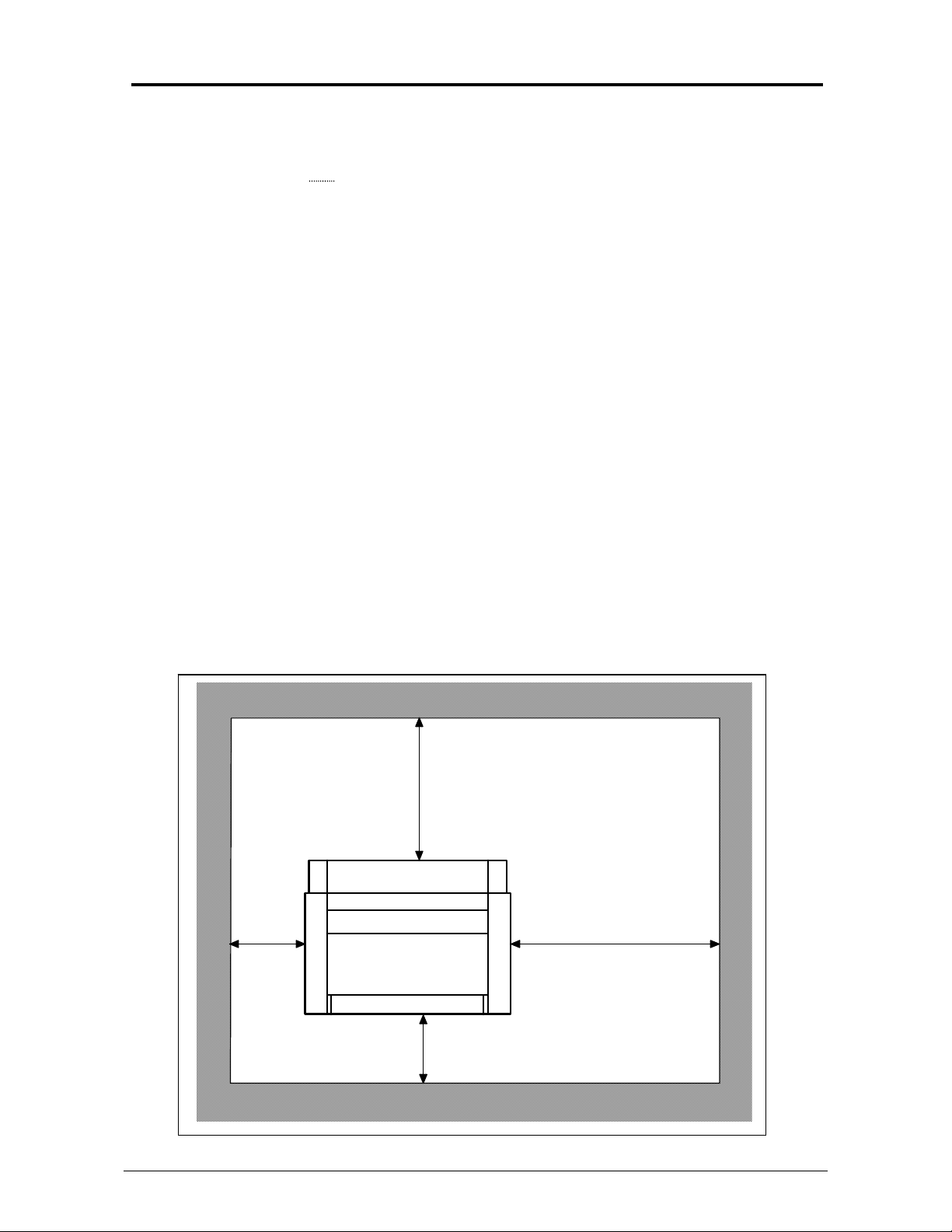
(9) Keep ample room around the equipment to ensure comfortable operation.
Required space is noted.
Rear
50cm
(20 inch)
or wider
Front
195cm (77 inch) or wider
120cm (48 inch) or wider
100cm (40 inch) or wider
1-2
Chapter 1 Before Use
Page 11

1. 2 Originals Prohibited from Duplication
It may be illegal to duplicate or copy certain types of originals and you may be punished by local or
regional laws, if copies are made of these types of originals. Please be aware of your local or
regional laws and which originals they forbid you to duplicate.
Some Examples:
[Originals prohibited from copying by the law(s)]
1. Do not copy Currency (Bill, Money, Bank Note, etc.), Government issued Negotiable
Instruments (National Bonds, Security, Local Debt Bonds, etc.).
2. Do not copy Foreign Currency or Foreign Negotiable Instruments.
3. Do not copy unused postal stamps or government postcards without permission to
make replica from said Governments.
4. Do not copy Government issued revenue stamps, certificate stamps that are
prescribed by Liquor Tax Act or the Commodity Tax Act.
[Special items which require your attention]
1. The government issues warnings if you are to copy private issued securities (stock
certificate, draft, check, goods ticket, etc.), commutation ticket or book of tickets, excluding
that some specific company copies such originals as many as it requires for its own
business.
2. We recommend you not copy originals as government issued passports, public or private
issued licenses, automobile inspection certification, ID and tickets passes or meals.
[Originals protected by the copyright]
It is prohibited to copy originals such as books, music, paintings, printed copies, maps,
drawings, movie posters and pictures which are protected by the copyright laws.
Please see your local or regional laws.
1-3
Chapter 1 Before Use
Page 12

1. 3 Features
(1) New Contact Development Technology with non-magnetic mono-component toner
Superior image quality High definition line, distinctive greyscale and consistent solid
black can be produced.
100% toner efficiency No waste toner is generated. Neither cleaning mechanism nor
waste toner receptacle is needed. It is environmentally
friendly and can reduce the running cost.
(2) Superior printing productivity
KIP9000’s fast print speed (240mm/sec) enables to process large volume of prints/copies
(11 A0 or E minute).
(3) Long parts life and low frequency of service maintenance
Service parts are durable for very long use and self-cleaning functions of KIP9000
enables the operator to enjoy quality images for a long term without maintenance.
(4) Pre-calibrated LED Head
All LED pixels are individually calibrated for the best image quality.
(5) Image Enhancement Technology
Dependent on the image, the best level of Image Enhancement is
automatically calculated.
(6) Installation of roll media and Toner Cartridge while printing
It is possible to install new roll media or add more toner without interrupting printing
operation.
(7) Long print
The maximum print length guaranteed is 6 meters (19.7 ft)(with plain paper).
The maximum possible length is 24 meters. (75ft) (Quality of print is not guaranteed.)
1-4
Chapter 1 Before Use
Page 13
1. 4 Specifications
Subject Specification
Model KIP 9000
Type Console
Printing method LED Array Electro Photography
Photoconductor Organic Photoconductive Drum
Print speed 240mm / second (11 A0 or E per minute - 22 A1 or D)
Exposure method LED Print Head
Resolution 600dpi x 600dpi
Print width Max : 914mm (36 inches)
Min : 297mm (11 inches)
Print length Max : Plain paper 6m when A0 or 36” (19.7ft)
Tracing paper A0 / 48 inch
Film A0 / 48 inch
NOTE : Longer print than the above specified maximum lengths
is available. However, KIP does not guarantee any result
including image quality and media feeding if the print is
longer than the above specified lengths.
Min 210mm (8.5”)
Warm up time Less than 6 minutes
(At 23 degrees centigrade, 60% RH and 230V)
First print time Shorter than 12 seconds (A0 or E)
Fusing method Heat roller fusing
Development Contact type mono component non-magnetic development system
One toner cartridge contains 500g.
Charging method Corona
Media feeding method Automatic roll feeding (4 Roll Decks)
Manual bypass feeding
NOTE : Multiple cut sheet feeding (50 sheets max) is available
when the size is narrower than A2 (594mm) or 24”.
Transfer method Corona
Separation method Corona and LED
Input power 220 - 240V (+6% / -10%), 16A and 50/60Hz in U.S.A. and Europe
Interface KIP Interface 8 (LVDS)
USB2.0 (5VDC max)
RS-232C (12VDC max)
Maximum power
consumption
Acoustic noise Less than 70db (Printing) NOTE : Impact noise is excluded.
Ozone Less than 0.05ppm (Average of 8 hours)
Dimensions 1360mm (Width) x 980mm (Depth) x 1265mm (Height) (54x39x50)
Weight About 400kg (880lbs)
Media Specified media
When 230V, 50/60Hz and Dehumidify Heater is ON
Stand by 0.9 Kwh
Printing 3.0 Kwh
Warm up 3.5 Kwh
Less than 55db (Stand by)
Plain paper 18 - 24# 70 - 90g/m
Tracing paper 18 - 24# 70 - 90g/m
Film 100 micrometer (4mil) or thinner.
2
2
1-5
Chapter 1 Before Use
Page 14
Subject Specification
Environmental
condition
Storage condition of
consumables
Temperature 10 - 32C (50 - 89F)
Humidity 20 - 80% RH
Print media Keep the media surely in a plastic bag and close to
shut out the humidity.
Toner Keep the toner cartridge away from the direct
sunlight, and store it in the condition of 0 - 35
and 10 - 85% RH.
NOTE
These specifications may be changed without notice.
o
C
1-6
Chapter 1 Before Use
Page 15

1. 5 Appearance
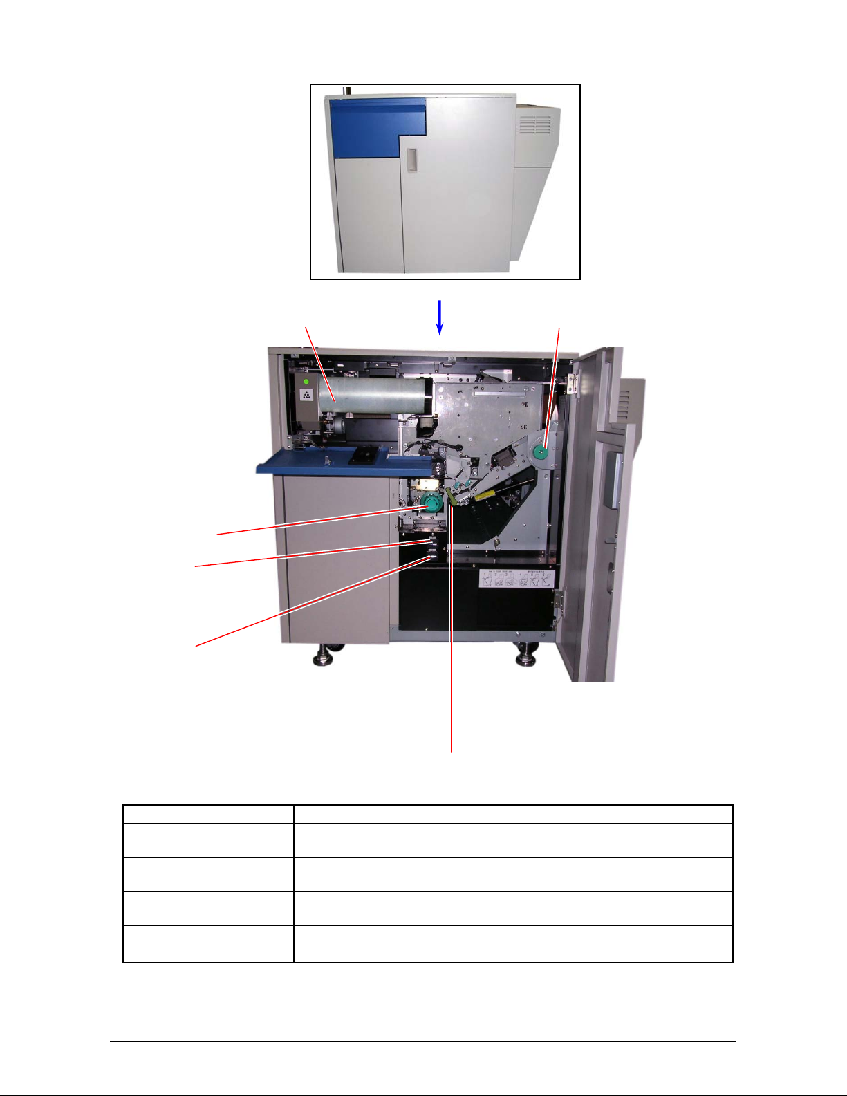
1. 5. 1 Front view
Power Switch Operation Panel User Interface
Bypass Feeder
Right Side Door
Roll Decks
Toner Cover
Media Indicator “in use” Indicators
Name of part Function
Power Switch Turns on/off the KIP9000.
Bypass Feeder Cut sheet media can be set here and fed into.
Multiple cut sheet feeding (50 sheets max) is available when the
size is narrower than A2 (594mm) or 24”.
Operation Panel Indicates the status of KIP 9000, error, mis-feed location and so
on.
Roll Decks There are 4 Roll Decks (Drawers are 3 but Roll Spools are 4.).
Each Roll Deck holds one roll of media.
Roll Deck 1 : (Top drawer)
Roll Deck 2 : (Middle drawer)
Roll Deck 3 : (Front side of bottom drawer)
Roll Deck 4 : (Rear side of bottom drawer)
Media Indicator Informs the size and the type of roll media loaded on each Roll
Deck.
Toner Cover Can access to the Toner Supplying Mechanism and replace the
Toner Cartridge.
Right Side Door Can access the internal of KIP9000 for removing the mis-fed
media.
Use Interface Touch Screen offers many kinds of user operation.
“in use” Indicators Shoes the Roll Deck that must not be opened.
1-7
Chapter 1 Before Use
Page 16
1. 5. 2 Right side view
Toner Cartridge Fuser Handle
Cutter Handle
Counter A
Counter B
Internal Transportation Unit Lever
Name of part Function
Cutter Handle Can cut the roll media manually if it has not been cut yet after it
was mis-fed.
Counter A Counts the linear meter / feet of total prints.
Counter B Counts the square meter / feet of total prints.
Internal Transportation
Unit Lever
Fuser Handle Can eject the mis-fed media manually from the Fuser Unit.
Toner Cartridge Includes 500 grams of toner.
Can unlock and open the Internal Transportation Unit for removing
the mis-fed media.
1-8
Chapter 1 Before Use
Page 17
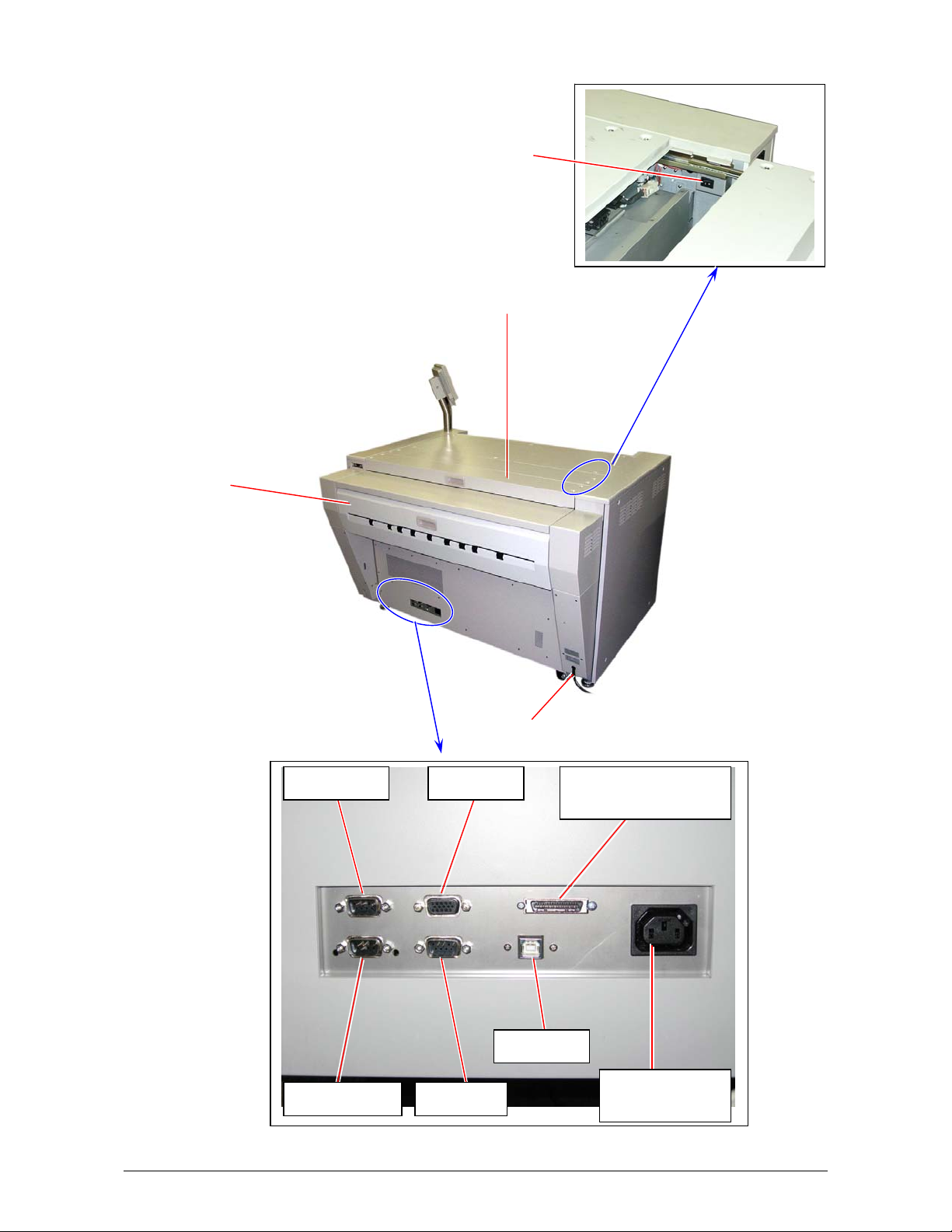
1. 5. 3 Rear view
Dehumidify Heater Switch
Top Rear Cover
Exit Cover
Power Cord
Folder Port
Shut Down Service
VGA Port
USB Port
Interface Connector
for IPS
Power Outlet
for IPS
1-9
Chapter 1 Before Use
Page 18

Name of part Function
Exit Cover Can remove the mis-fed media around Fuser section.
Interface Connector for
IPS
Folder Port Connects the cable from the finishing device (Folder, etc).
Shut Down Connects the Shutdown Signal Cable.
Service For Service personnel only
VGA Port Connect the cable here, which comes from the controller VGA port
USB Port Connect the cable here, which comes from the controller USB Key
Top Rear Cover Can access the Dehumidify Heater Switch.
Power Outlet for IPS In case you place a controller unit outside of the KIP 9000, it is
Power Cord Connect to the wall outlet.
Dehumidify Heater
Switch
Connects the cable from the controller unit.
D-Sub Connector 36 pins, 3.3Vdc maximum (large)
12Vdc maximum - Not used in North America
KIP 9000 will send a shutdown signal to the controller through this
cable. 12Vdc maximum
by UL-Listed cable for Touch screen LCD. 5Vdc maximum
Connector Type B for Touch screen LCD. 5Vdc maximum
possible to supply AC power from the KIP 9000 to the controller
unit if you connect the power cord to this outlet. (220 - 240V, 3A
maximum)
Connected controller unit must meet UL Standard 60950-1 (ULListed)
NOTE: Specification for Power Cord used in North America
Use the following type of Power Cord for a controller unit.
(1) Rating minimum 250VAC 7A
(2) Plug Type IEC60320: C13
(3) Socket Type IEC60320: C14
(4) Cord H05VV-F 3G-0.75mm
SVT3x18AWG
(5) UL-Listed
Turns on/off the Dehumidify Heater.
1-10
Chapter 1 Before Use
Page 19

1. 5. 4 Operation Panel
Operation Panel on offers several user operations.
Names and functions of key and indication LED are as follows.
1 2 3 4 5 8 12 15
WIRE CLEAN EXP-CLEAN
6 7 9 10 11 13 14 16
No. Name of part Function Refer to
1 Ready Indicator Flashes green when KIP 9000 is warming up, and
2 Open Indicator Lights orange when any door or unit is open or
3 Toner Empty
Indicator
4 Roll Empty Indicator Lights red if the roll media in use is empty. 2-4
5 Mis-feed Indicator Lights red when the print media is mis-fed. 3-2
6 WIRE-CLEAN Key Starts cleaning for the Image Corona Wire. 3-33
7 EXP-CLEAN Key Starts cleaning for the LED Head. 3-34
8 Roll Deck Indicator Shows the present selection of roll to perform initial
9 SELECT Key Selects a roll to perform initial cut. 2-23
10 CUT Key Performs initial cut for the selected roll. 2-23
11 Mis-feed Location
Indicator
12 Density Indicator Shows the present selection of density level. 13 COPY DENSITY
Key
14 MENU Key
Key
Key
* Key
ENTER Key
PAPER DECK
1234
SELECT CUT
MF
D1
D2
D3
EXIT
PF
D4
COPY DENSITY
MENU ENTER ONLINE
lights green when it is ready.
unlocked.
Flashes red when the toner is near empty. (Toner
Cartridge has no Toner).
Lights red when the toner is completely empty.
(Developer Unit has no toner. No more print is
available.)
cut.
Shows the location of mis-fed media by lighting the
concerning LED.
Changes the density level for making the print density
darker or lighter.
[MENU], [ ], [ ] and [ENTER] Keys are used
in User Modes.
(The service personnel may use them also in the field
service.)
[ * ] Key is used to stop the alarm sound.
page;
2-2
3-26
2-17
2-23
3-2
-
2-25
to
2-72
1-11
Chapter 1 Before Use
Page 20

No. Name of part Function Refer to
page;
15 Status Display Indicates kinds of information such as error codes, mis-
feed codes, and etc.
16 ONLINE Key &
Indicator
The ONLINE Indicator lights green when KIP9000 is
online, and it is put out when offline.
ONLINE Key switches between online and offline, and
also cancels the User Mode.
-
2-25
to
2-72
1-12
Chapter 1 Before Use
Page 21
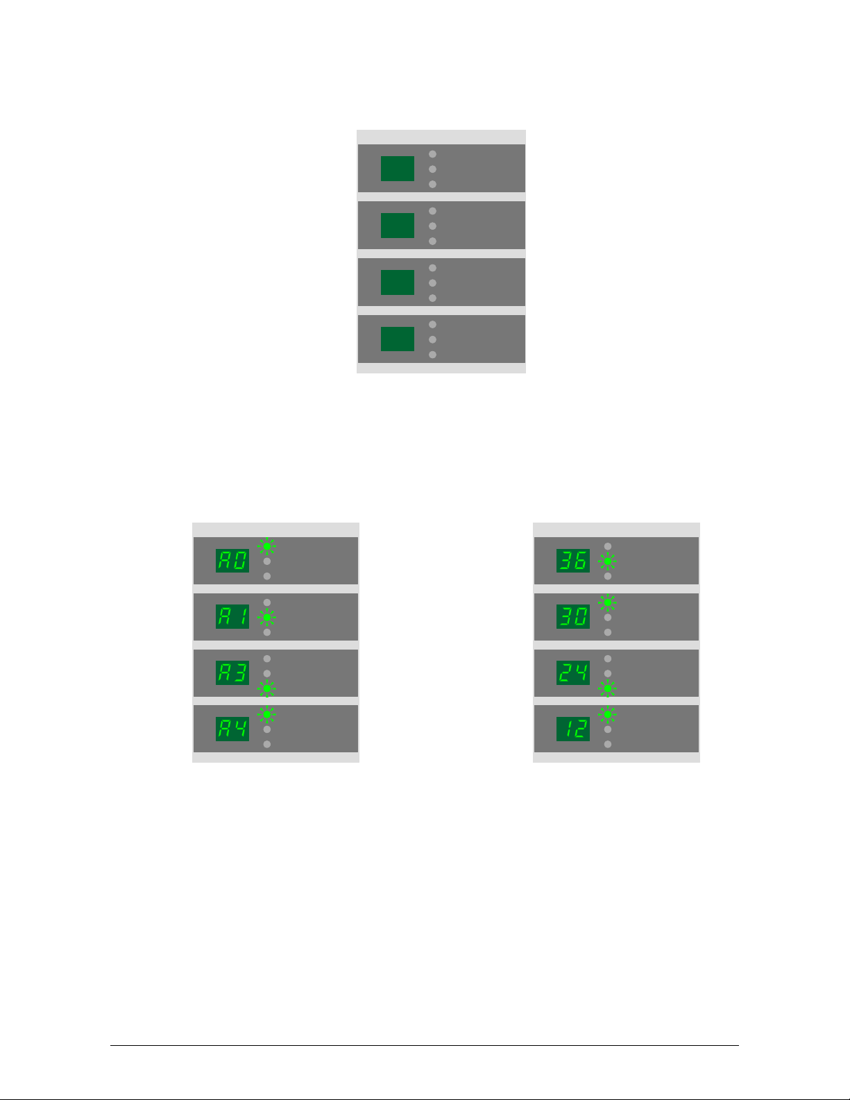
1. 5. 5 Media Indicators
The Media Indicator on the right front of KIP9000 informs the size (width) and the type of roll media
installed in each Roll Deck.
1
2
3
4
Example 1 : Metric mode Example 2 : Inch mode
Roll Deck 1 : A0 plain paper Roll Deck 1 : 36” vellum
Roll Deck 2 : A1 tracing paper Roll De ck 2 : 30” plain paper
Roll Deck 3 : A3 film Roll Deck 3 : 24” film
Roll Deck 4 : A4 plain paper Roll Deck 4 : 12” plain paper
1
2
3
plain paper
vellum / tracing
film
plain paper
vellum / tracing
film
plain paper
vellum / tracing
film
4
plain paper
vellum / tracing
film
plain paper
vellu m/ tracing
film
plain paper
vellu m/ tracing
film
plain paper
vellu m/ tracing
film
plain paper
vellu m/ tracing
film
1
2
3
4
plain paper
vellum / tracing
film
plain paper
vellum / tracing
film
plain paper
vellum / tracing
film
plain paper
vellum / tracing
film
1-13
Chapter 1 Before Use
Page 22
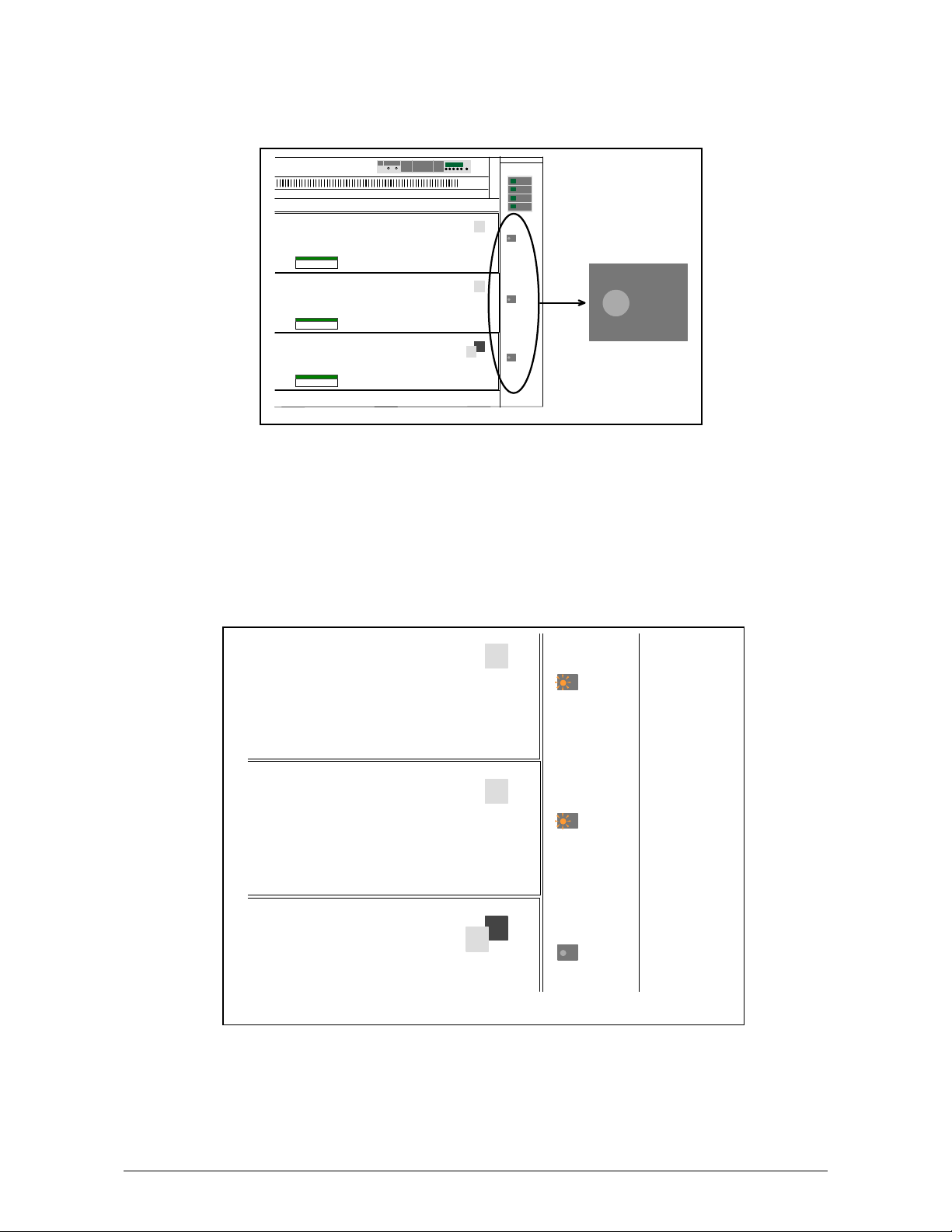
1. 5. 6 “in use” Indicators
3 “in use” Indicators on the right front of KIP9000 are related with 3 drawers respectively, and
inform the operator which drawer must not be opened during printing.
One or two “in use” Indicator light orange when the KIP 9000 is on printing.
Do not open the drawer if the concerning “in use” Indicator is lighting orange.
The drawer can be opened even if the KIP9000 is on printing if the concerning “in use” Indicator is
not lighting.
Example : Top and middle drawer can not be opened as the “in use” Indicators for them are
lighting orange.
Only the bottom drawer can be opened as its “in use” Indicator is not lighting.
1
2
in use
4
3
1
inuse
2
inuse
4
3
inuse
1-14
Chapter 1 Before Use
Page 23

Reference
Even if the KIP9000 is printing, it is possible to open the drawer and replace/install the roll
media without interrupting the print operation. However, it is not necessarily allowed to open
any drawer at any time. A certain drawer can not be opened in the following situations.
1. When the roll media is fed from a certain drawer, this drawer can not be opened.
2. When the media (including cut sheet media) fed from other drawer is passing through the
media path in a certain drawer, this drawer can not be opened.
See the following section diagram. Media feeding paths from each Roll Deck is integrated into
one path in the middle drawer. When the KIP 9000 is printing with the roll media fed from the
Roll Deck 1 for example, only the bottom drawer can be opened. (“in use” Indicators for top
and middle drawers will light orange in this case.)
Top Drawer is not
allowed to open.
in use
Roll Deck 1
Middle Drawer is not
allowed to open.
in use
Roll Deck 2
Bottom Drawer is
allowed to open.
in use
Roll Deck 3
Roll Deck 4
D4
1-15
Chapter 1 Before Use
Page 24

Chapter 2
Basic Operations
Page
2. 1 Turning on the KIP 9000 2- 2
2. 2 Turning off the KIP 9000 2- 3
2. 3 Setting the Roll Media into Roll Deck 2- 4
2. 3. 1 Roll 1, 2 & 3 2- 5
2. 3. 2 Roll 4 2-11
2. 4 Setting Cut Sheet Media to Bypass Feeder 2-13
2. 4. 1 Multi-feeding of cut sheet media 2-14
2. 4. 2 Singular feeding of cut sheet media 2-15
2. 5 Replacing the Toner Cartridge 2-17
2. 6 Dehumidifying the Roll Media 2-21
2. 7 Initial Cut (Straighten the leading edge of roll media) 2-23
2. 8 User Modes 2-25
2. 8. 1 User Mode 1 (Test Print) 2-26
2. 8. 2 User Mode 2 (Calendar setting) 2-28
2. 8. 3 User Mode 3 (Warm Sleep Mode ON / OFF & timer setting) 2-33
2. 8. 4 User Mode 4 (Cold Sleep Mode timer setting) 2-37
2. 8. 5 User Mode 5 (Automatic paper cut at power ON) 2-40
2. 8. 6 User Mode 6 (Transfer Support LED ON/OFF [Film]) 2-43
2. 8. 7 User Mode 7 (Alarm ON / OFF) 2-46
2. 8. 8 User Mode 8 (Choice of Standard / Special Print Mode [Plain paper]) 2-49
2. 8. 9 User Mode 9 (Choice of Standard / Special Print Mode [Tracing paper]) 2-53
2. 8.10 User Mode A (Choice of Standard / Special Print Mode [Film]) 2-56
2. 8.11 User Mode B (Selection of Image Enhancement Mode) 2-59
2. 8.12 User Mode C (Print on TE margin area) 2-62
2. 8.13 User Mode D (Error check level for E-26 error) 2-66
2. 8.14 User Mode E (Error check level for E-28 error) 2-69
2. 8.15 User Mode F0 to Fb (Fold settings applied when Bay Folder is connected) 2-72
2-1
Chapter 2 Basic Operations
Page 25
2. 1 Turning on the KIP 9000
1. Plug the KIP 9000 into an exclusive wall outlet.
NOTE
Please confirm the outlet satisfies the following condition before plugging the KIP 9000 into.
U.S.A. / Europe 220 - 240V (+6% / -10%), 16A, 50/60Hz
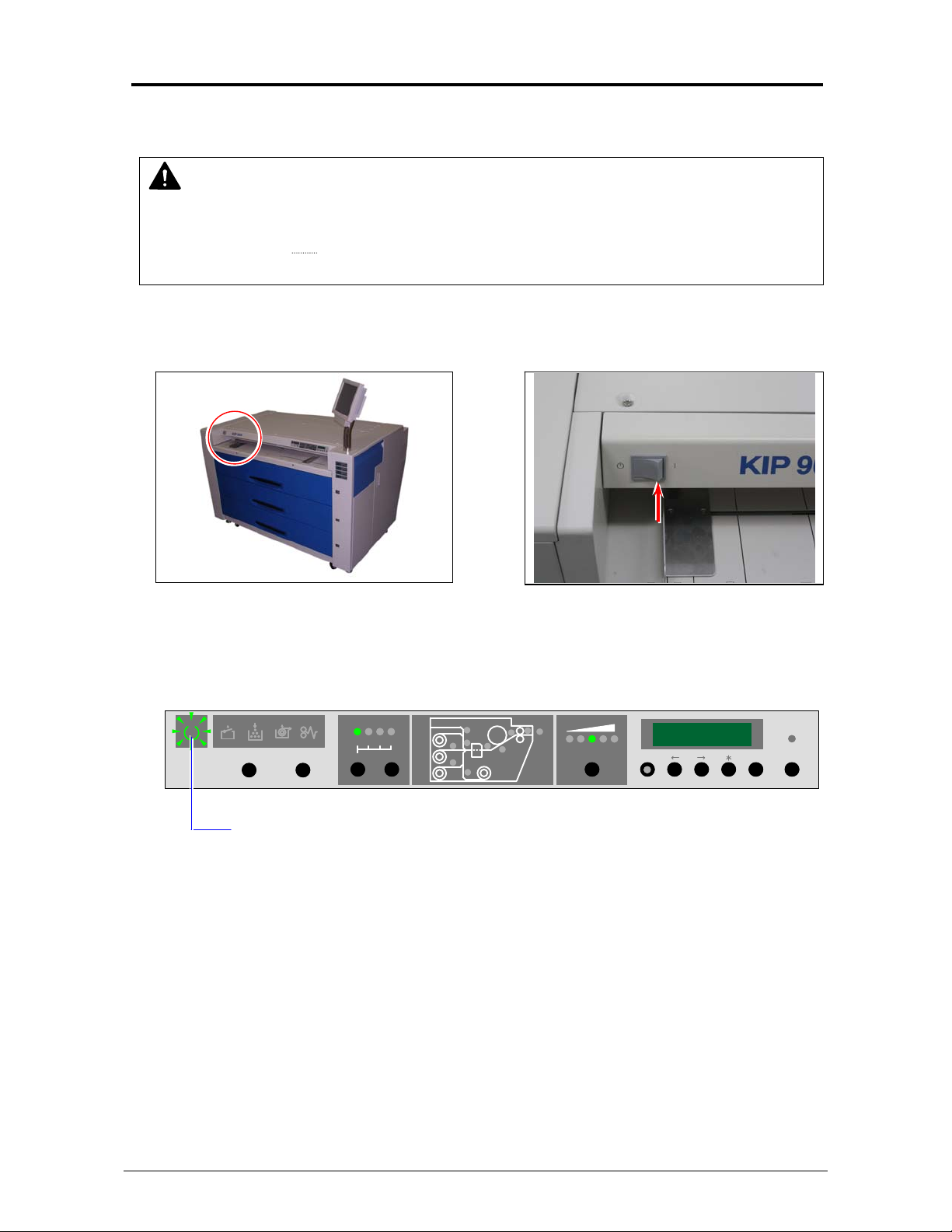
2. Press “|” side of Power Switch to turn on the KIP 9000.
3. KIP 9000 starts warming up the Fuser Unit, and the Ready Indicator on the Operation Panel
starts flashing.
WIRE CLEAN EXP-CLEAN
Ready Indicator flashes.
4. The Ready Indicator lights when the KIP9000 gets ready about 6 minutes later.
Send a print job or copy job from the outer devices.
PAPER DECK
1234
SELECT CUT
MF
D1
D2
D3
EXIT
PF
D4
COPY DENSITY
MENU ENTER ONLINE
2-2
Chapter 2 Basic Operations
Page 26
2. 2 Turning off the KIP 9000
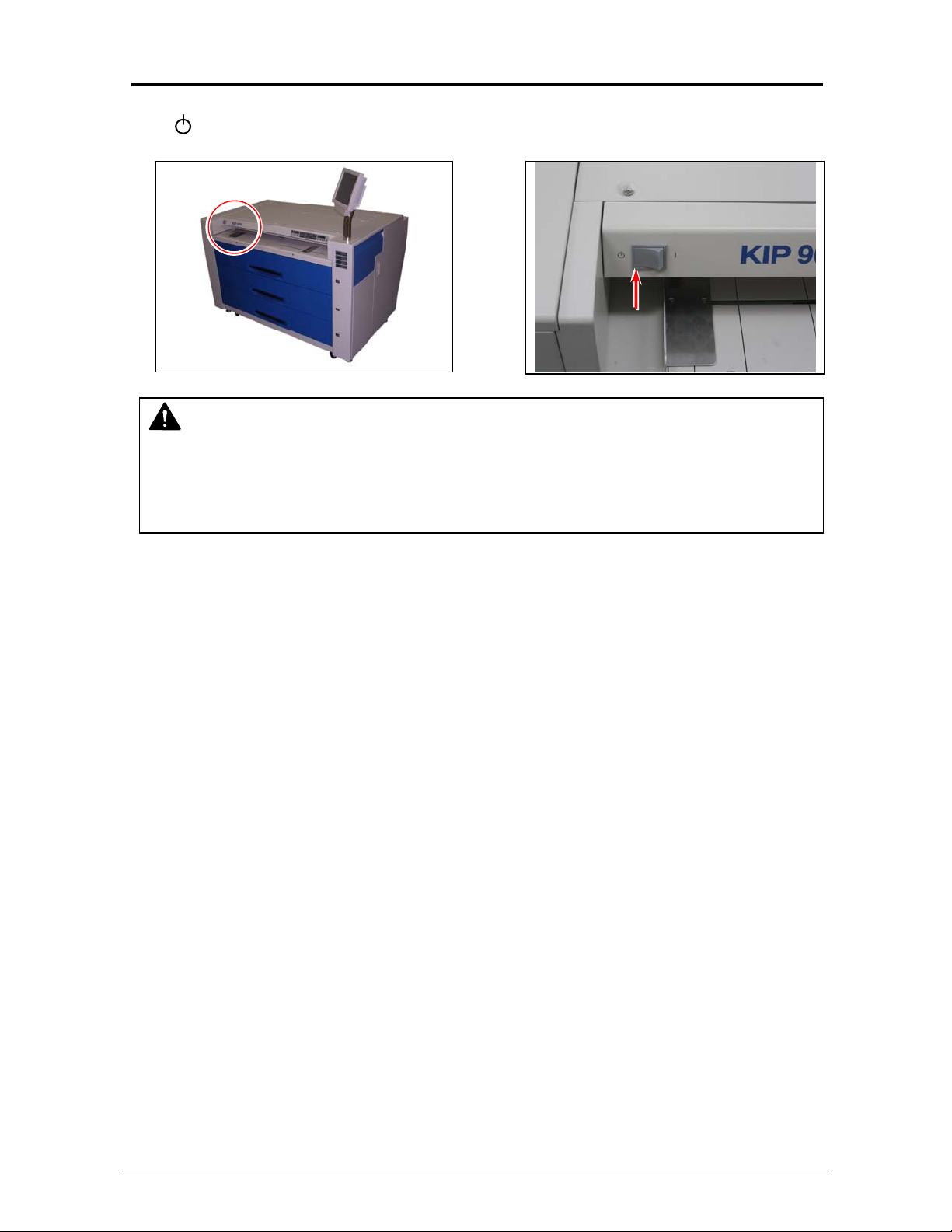
Press “ ” side of Power Switch to turn off the KIP 9000.
NOTE
The controller unit starts shutdown process after turning off the KIP9000, and it will take
about 2 minutes until complete shut down. Do not unplug the KIP 9000 from the outlet for
about 2 minutes after turning off therefore. The controller unit may be broken if the KIP 9000
is unplugged before the completion of shut down process.
2-3
Chapter 2 Basic Operations
Page 27
2. 3 Setting the Roll Media into Roll Deck
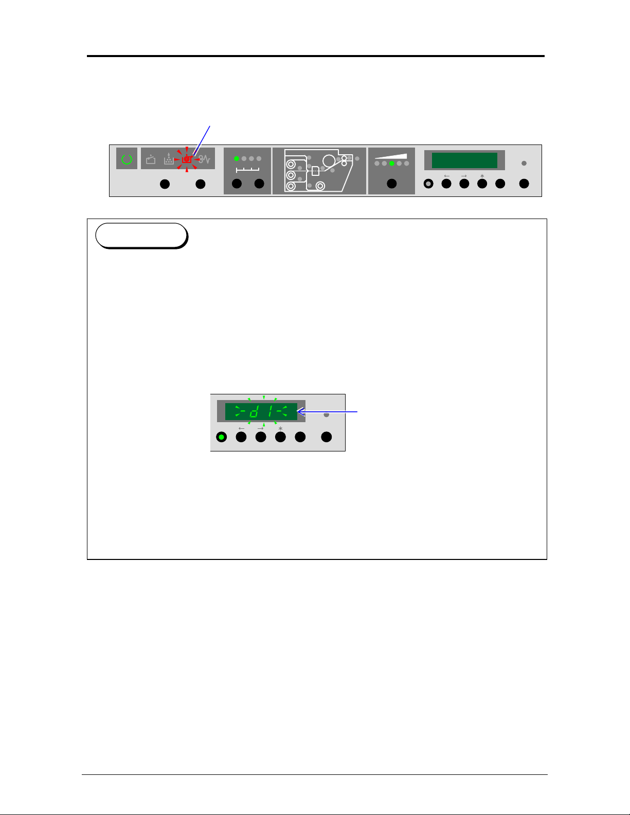
The Roll Empty Indicator on the Operation Panel flashes in red when the used roll media is
emptied during printing. Install a new roll media.
Roll Empty Indicator
WIRE CLEAN EXP-CLEAN
Reference
(1) Even if the KIP9000 is printing, it is possible to open the drawer and replace/install the roll
media without interrupting the print operation. However, it is not necessarily allowed to
open any drawer at any time. Do not open the drawer when its “in use” Indicator is lighting.
Refer to [1.5.6 “in use” Indicator] on page 1-14 for the detail.
(2) Some Media Source Code is indicated on the Status Display during print to show which
media source is used currently. (This is not indicated when printer is not on printing.)
If the remainder of roll becomes smaller than ¼ of new one, this code flashes to show it is
“near empty”.
Media Source Code flashes when
the roll media is near empty.
The followings are the correspondence of Media Source Codes and media sources.
- d 1 - : Roll 1 is used.
- d 2 - : Roll 2 is used.
- d 3 - : Roll 3 is used.
- d 4 - : Roll 4 is used.
- b P - : Bypass Feeder is used.
PAPER DECK
1234
SELECT CUT
MENU ENTER ONLINE
MF
D1
D2
D3
D4
EXIT
PF
COPY DENSITY
MENU ENTER ONLINE
2-4
Chapter 2 Basic Operations
Page 28

2. 3. 1 Roll 1, 2 & 3
Install a new roll media onto Roll 1, 2 and 3 using the following directions.
Roll 1
Roll 2
Roll 3
1. Draw out the concerning Roll Deck.
2-5
Chapter 2 Basic Operations
Page 29
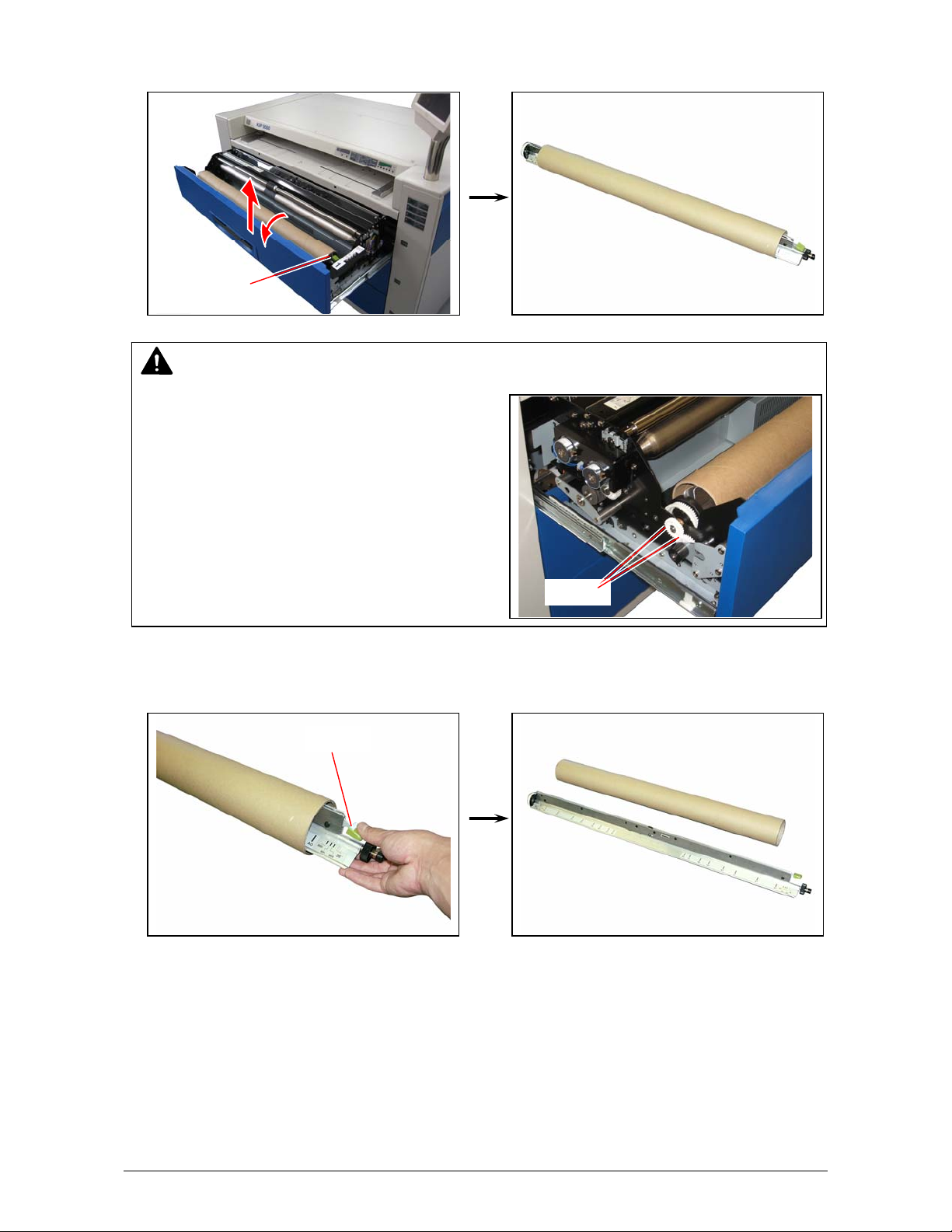
2. Retrieve the Roll Spool to the arrow direction a little to disengage the gears on the left, and
remove the Roll Spool from the deck.
Roll Spool
NOTE
If the Roll Spool is removed without disengaging
the gears on the left, these gears will be broken.
3. Unlock the core of roll press down the green lever on the right of the Roll Spool, and pull out
the Roll Spool from the core.
Lever
Gears
2-6
Chapter 2 Basic Operations
Page 30
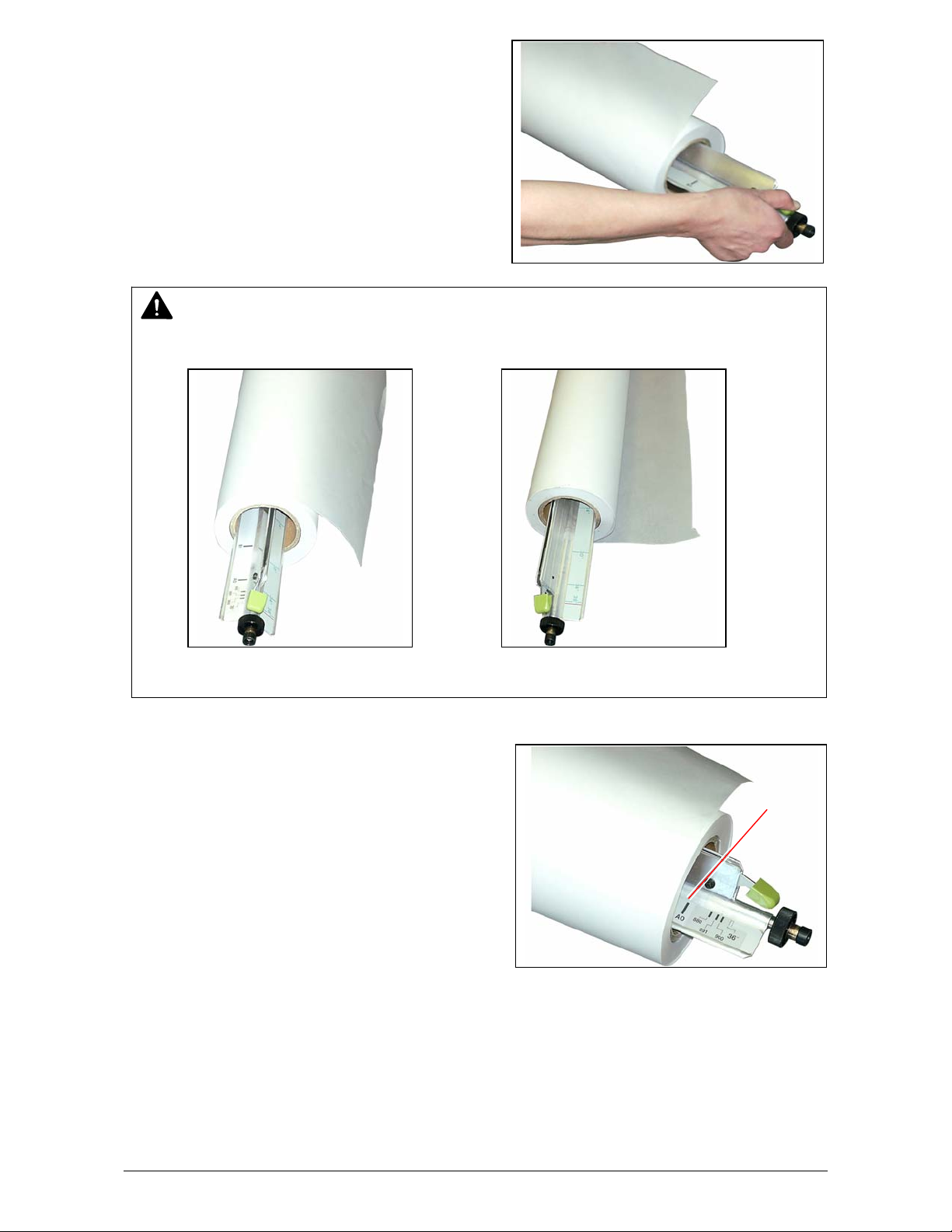
4. Pressing down the green lever, insert the Roll
Spool to the new roll media.
NOTE
Do not install the roll media with wrong direction.
Correct Wrong
5. Align the edge of roll media with the concerning
size guide, then release the green lever. The roll
media is firmly fixed to the Roll Spool.
Size guide
2-7
Chapter 2 Basic Operations
Page 31

6. Return the Roll Spool to the Roll Deck.
NOTE
The driving belt inside of the Roll Deck must be
flat and evenly contact on the bottom of black
small roller on the right of Roll Spool.
If it is twisted or not contacting the black small
roller properly, correctly it.
Black small roller Driving belt
Correct Wrong (Belt is twisted.)
2-8
Chapter 2 Basic Operations
Page 32

7. Using a slit on each drawer, cut off the leading part of roll media with a cutter knife to straighten
the leading edge.
Slit
NOTE
Do not feed any media with tape or adhesive remaining on it. It is best to trim at least one full
revolution from the roll when installing a new roll.
8. Insert the leading edge of media between feeding rollers, and rotate the upper feeding roller to
pinch the leading edge (1-2cm) with the rollers.
Feeding rollers
NOTE
The Roll Deck 3 only has a positioning hole. (Other Rolls do not have it.)
Feed the roll media until its leading edge comes to appear in the hole, and place the leading
edge at the center of the hole.
Positioning hole
2-9
Chapter 2 Basic Operations
Page 33

9. Set the Media Selector correctly according to the type of media installed.
If any inch size media is installed, select either “ENGINEERING” or “ARCHITECTURE” as well.
(“ENGINEERING” is selected when the button is up, and “ARCHITECTURE” when it is down.)
NOTE
Set the Media Selector to correct media type. (Including Architecture/Engineering selection)
Wrong setting of Media Selector could cause unexpected defective printing result.
10. Close the Roll Deck.
2-10
Chapter 2 Basic Operations
Page 34

2. 3. 2 Roll 4
The way of paper installation to Roll 4 is a little different from the way for other Rolls because of
the different location of Roll 4’s feeding rollers. This section instructs only the operation individually
required for Roll 4. Refer to [2.3.1 Roll 1, 2 & 3] on page 2-5 for the rest of common operations.
1. Draw out the bottom Roll Deck.
2. Remove the Roll Spool from the Roll Deck, pull
out the Roll Spool from the old roll media, and
set the new roll media onto the Roll Spool.
NOTE
Please keep the correct direction as the following left photo.
(It is the same way you make for Roll 1, 2 & 3.)
Correct Wrong
2-11
Chapter 2 Basic Operations
Page 35

3. Return the Roll Spool to the Roll Deck 4.
r
4. Insert the leading edge of media under the
feeding roller.
5. Rotate the green knob clockwise to pinch the
leading edge (about 1-2cm) with the feeding
rollers.
6. Close the Roll Deck 4.
Feeding
rolle
Roll media
Knob
2-12
Chapter 2 Basic Operations
Page 36

2. 4 Setting Cut Sheet Media to Bypass
Feeder
Cut sheet media can be fed into KIP9000 from the Bypass Feeder. Orientation, length and
availability of multi-feeding are specified for each media width separately as follows.
Metric size
Width of cut
sheet media
Inch size
Width of cut
sheet media
NOTE
(1) Availability of orientation for each media size is illustrated on the Bypass Feeder.
Please follow the illustration when setting the cut sheet media.
Landscape Portrait
Orientation is specified
(2) Multi-feeding is available if the cut sheet media is narrower than A2 (594mm) or 24”.
Refer to [2.4.1 Multi-feeding of cut sheet media ] on page 2-14.
Available orientation Available length Availability of multi-
feeding
297mm Landscape o nly 210mm only Available
420mm Landscape o nly 297mm only Available
594mm Landscape o nly 420mm only Available
841mm Portrait & Landscape Not specified (But it must be longer than 440mm.) Not available
Available orientation Available length Availability of multi-
feeding
11” Landscape only 8.5” only Available
12” Landscape only 9” only Available
17” Landscape only 11” only Available
18” Landscape only 12” only Available
22” Landscape only 17” only Available
24” Landscape only 18” only Available
30” Portrait & Landscape Not specified (But it must be longer than 440mm.) Not available
34” Portrait & Landscape Not specified (But it must be longer than 440mm.) Not available
36” Portrait & Landscape Not specified (But it must be longer than 440mm.) Not available
2-13
Chapter 2 Basic Operations
Page 37

2. 4. 1 Multi-feeding of cut sheet media
Multiple cut sheet feeding (50 sheets max) is available when the size is narrower than A2 (594mm)
or 24”. The followings are the sizes that can be fed by multi-feeding. (Orientation must be
landscape)
Metric : 297mm x 210mm (A4) Inch : 11” x 8.5” 18” x 12”
420mm x 297mm (A3) 12” x 9” 22” x 17”
594mm x 420mm (A2) 17” x 11” 24” x 18”
NOTE
(1) Do not attempt to make multi-feeding with other sizes of media as it will result in mis-feed
or duplicate feeding. The internal mechanism of KIP9000 may be broken in the worst case.
(2) Do not leave the cut sheet media on the Bypass Feeder for a long time as it will get
moisture. Such media will result in mis-feed or defective image.
(Keep the media in a plastic bag to block the moisture.)
1. Select the bypass feeding mode on the outer device.
2. Slide the Cut Sheet Guides and place at the
requested size guides.
3. Arrange the edges of media, put the media on the Bypass Feeder, and move them forward
until the leading edges contact the feeding roller.
NOTE
Landscape feeding only is available.
Feeding roller
Cut Sheet Guide
2-14
Chapter 2 Basic Operations
Page 38

2. 4. 2 Singular feeding of cut sheet media
Larger cut sheet media than A2 (594mm) or 24” can be fed into KIP9000 by singular feeding only.
NOTE
Do not leave the cut sheet media on the Bypass Feeder for a long time as it will get
moisture. Such media will result in mis-feed or defective image. (Keep the media in a plastic
bad to block the moisture.)
1. Select the bypass feeding mode on the outer device.
2. Slide the Cut Sheet Guides and place at the
requested size guides.
3. Put the media on the Bypass Feeder and move it forward until the leading edge contacts the
feeding roller.
Feeding roller
Cut Sheet Guide
2-15
Chapter 2 Basic Operations
Page 39

NOTE
As curled cut sheet media will cause a mis-feed, straighten the media as far as possible
before printing.
And also please set the media by “curl down” direction as a mis-feed can be avoided.
Setting of media by “curl up” direction tends to result in a mis-feed.
Correct (curl down) Incorrect (curl up)
2-16
Chapter 2 Basic Operations
Page 40

2. 5 Replacing the Toner Cartridge
The Toner Empty Indicator on the Operation Panel flashes when the toner is “near empty”, and it
lights when the toner is completely empty. Replace the Toner Cartridge when it lights.
Toner Empty Indicator
WIRE CLEAN EXP-CLEAN
Reference
(1) Even if the KIP 9000 is on printing, it is possible to replace the Toner Cartridge without
interrupting printing.
(2) It is still possible to make some more printing when the Toner Empty Indicator is flashing,
but the toner will be soon emptied completely and the KIP9000 will no more be able to
continue printing. For avoiding machine down, prepare a new Toner Cartridge before the
Toner Empty Indicator starts flashing.
NOTE
(1) The KIP9000 Toner Cartridge is embedded with the IC Tag for an exclusive use on
KIP9000. Even if the Toner Cartridge for other models is installed, the KIP9000 does not
operate with indicating an error code “C-01”.
(2) Once the Toner Cartridge become empty with the toner, the KIP9000 recognizes its IC Tag
information. The same Toner Cartridge can no more be installed onto the KIP9000 after
that. The KIP9000 does not operate with indicating an error code “C-01” if once emptied
Toner Cartridge is installed.
1. Open the Toner Cover on the right face.
PAPER DECK
1234
SELECT CUT
MF
D1
D2
D3
EXIT
PF
D4
COPY DENSITY
MENU ENTER ONLINE
Toner Cover
2-17
Chapter 2 Basic Operations
Page 41

2. Open the Cartridge Cover.
Cartridge Cover
Cartridge Cover
3. Catching the left end of Toner Cartridge, rotate it half revolution until the toner supplying hole of
the cartridge becomes visible in the notch as the following right photo.
Catch here
Toner Cartridge
Toner supplying hole
NOTE
(1) The toner will drop and will dirt the floor if the cartridge is removed without directing its toner
supplying hole up.
(2) Catch the left end of Toner Cartridge. If you catch its body as the following incorrect
example, the toner will spill out.
Correct Incorrect
2-18
Chapter 2 Basic Operations
Page 42

4. Remove the Toner Cartridge catching its left end.
5. Shake the new Toner Cartridge fully to loosen
the toner.
6. Install the new Toner Cartridge with its green
seal up.
7. Rotate the Toner Cartridge quarter revolution, and then strip off the green seal.
Green seal
Strip off the seal.
2-19
Chapter 2 Basic Operations
Page 43

8. Rotate the cartridge quarter revolution more to place the toner supplying hole on the bottom.
NOTE
Be sure to place the toner supplying bole on the bottom. Otherwise the KIP9000 will show Toner
Empty Error soon as the toner can not be supplied with this state.
9. Close the Cartridge Cover.
10. Close the Toner Cover.
Cartridge Cover
Toner Cover
2-20
Chapter 2 Basic Operations
Page 44

2. 6 Dehumidifying the Roll Media
Printing with a humidified media will result in several printing defects. The most popular defects are
“creasing” and “image void”.
If the roll media is kept in the Roll Deck for a long time with being exposed to the air, the media
tends to be more humidified and results in the above defects with higher frequency. To avoid this
situation as far as possible, the KIP 9000 is provided with the Dehumidify Heater for drying the roll
media in the Roll Deck.
If the above defects can be seen when the air is very humidified (higher than 60%), try to turn on
the Dehumidify Heater as the defects may be resolved.
1. Open the Top Rear Cover.
Expected Print
Expected Print
Creasing (of media)
If media is humidified ;
Image void
If media is humidified ;
Top Rear Cover
2-21
Chapter 2 Basic Operations
Page 45

2. There is a Dehumidify Heater Switch on the right.
p
Press “H” to turn on the Dehumidify Heater, and press “L” to turn it off.
Reference
(1) KIP9000 offers some kinds of operation mode of Dehumidify Heater, which specify when
the heater should work. Your service personnel select the best operation mode at machine
installation considering your usage environment. If “creasing” or “image void” starts to
occur so frequently when the usage environment changes (because of seasonal reason
and etc) during normal use, it may be fixed if the operation mode is changed to
other ones. Consult your service personnel in such case. (User can not change the mode.)
(2) The KIP9000 must be plugged into the outlet for operating the Dehumidify Heater. (Some
operation mode enables the Dehumidify Heater to work even if the KIP9000 is turned off at
night if only it is plugged in. Do not plug out the KIP9000 in such case especially.)
(3) Dehumidify Heater is just a possibility to fix “creasing” or “image void”, but it is NOT the
complete solution for such defects.
installed to the Roll Deck, it will be no use in turning on the Dehumidify Heater. The user
needs to take great care for preventing the printing media from being humidified.
• Do not unpack the media until right before it is to be installed to the machine.
• When the air is very humidified, do not leave the roll media in the deck. Remove it from
the deck,
If the media has been already humidified before
ut it in a plastic bag and close firmly to avoid the humidity.
Dehumidify Heater Switch
2-22
Chapter 2 Basic Operations
Page 46

2. 7 Initial Cut (Straighten the leading edge
of roll media)
The leading part (240mm) of roll media can be cut off to have a straight edge.
Initial Cut can be performed with SELECT Key, CUT Key and Roll Deck Indicator on the Operation
Panel.
Roll Deck Indicator
WIRE CLEAN EXP-CLEAN
SELECT Key CUT Key
1. Pressing the SELECT Key, select the roll media to which the Initial Cut is to be performed.
SELECT CUT
Leading part of roll media
PAPER DECK
1234
SELECT CUT
PAPER DECK
1234
MF
D1
D2
D3
EXIT
PF
D4
PAPER DECK
1234
SELECT CUT
COPY DENSITY
MENU ENTER ONLINE
2-23
Chapter 2 Basic Operations
Page 47

2. Press the CUT Key to perform the Initial Cut. The leading part of selected roll is cut and ejected
automatically. (The LED flashes during the Initial Cut.)
Reference
Initial Cut is not available when in warming up or when the Roll Deck is open. All LED of Roll
Deck Indicator are put out in this case.
PAPER DECK
1234
SELECT CUT
2-24
Chapter 2 Basic Operations
Page 48

2. 8 User Modes
KIP 9000 provides 14 User Modes.
Name of
User Mode
User Mode 1 Test print U1.
User Mode 2 Calendar setting U2.
User Mode 3 Warm Sleep Mode ON / OFF & timer setting U3.
User Mode 4 Cold Sleep Mode timer setting U4.
User Mode 5 Automatic paper cut at power on U5.
User Mode 6 Transfer Support LED ON/OFF [Film] U6.
User Mode 7 Alarm ON / OFF U7.
User Mode 8 Choice of Standard / Special Print Mode [Plain paper] U8.
User Mode 9 Choice of Standard / Special Print Mode [Tracing paper] U9.
User Mode A Choice of Standard / Special Print Mode [Film] UA.
User Mode B Selection of Image Enhancement Mode Ub.
User Mode C Print on TE margin area UC.
User Mode D Error check level for E-26 error Ud.
User Mode E Error check level for E-28 error UE.
The following optional User Modes (F0 to Fb) are normally not accessible, but become accessible
only when the folder is connected. Ask your service personnel for the detail of it and these modes
are not used in the North America.
Name of
User Mode
User Mode F
Description User Mode Code
Description User Mode Code
Fold settings applied when Bay Folder is connected
F0 : Folding type for folding method 1 UF0.
F1 : Width of fan folding for folding method 1 UF1.
F2 : Margin for folding method 1 UF2.
F3 : Folding type for folding method 2 UF3.
F4 : Width of fan folding for folding method 2 UF4.
F5 : Margin for folding method 2 UF5.
F6 : Folding type for folding method 3 UF6.
F7 : Width of fan folding for folding method 3 UF7.
F8 : Margin for folding method 3 UF8.
F9 : Folding type for folding method 4 UF9.
FA : Width of fan folding for folding method 4 UFA.
Fb : Margin for folding method 4 UFb.
2-25
Chapter 2 Basic Operations
Page 49

2. 8. 1 User Mode 1 (Test Print)
[Function]
An internal test pattern image can be printed out for checking image or machine operation.
KIP9000 automatically selects the roll media and print size.
[Operation]
1. Press the [ MENU ] Key once to select the User Mode 1. [ MENU ] Key lights green and the
Status Display indicates “U1.”
2. The 4th, 5th and 6th digits indicates the status of KIP 9000.
- - - (flashing) : Test print is not available.
ooo (lighting) : Test print is available.
ooo (flashing) : On test printing
Status of KIP 9000
MENU ENTER ONLINE
Press [ MENU ] once.
MENU ENTER ONLINE
MENU ENTER ONLINE
2-26
Chapter 2 Basic Operations
Page 50

3. Press the [ ENTER ] Key when “ooo” is lighting. Test print is started and “ooo” flashes.
MENU ENTER ONLINE
MENU ENTER ONLINE
4. When test print is finished, “ooo” stops flashing and lights. Press the [ ONLINE ] Key to cancel
the User Mode 1.
MENU ENTER ONLINE
MENU ENTER ONLINE
2-27
Chapter 2 Basic Operations
Page 51

2. 8. 2 User Mode 2 (Calendar setting)
[Function]
Calender setting can be corrected if wrong. (KIP9000 memorizes calendar information on its
circuit.)
NOTE
(1) KIP9000 can operate without problem even if the calendar setting is wrong.
(2) The calendar setting is used for diagnostics purpose. If some error or mis-feed occurs,
KIP9000 records it with the information “when” it occurred based on the calendar setting
set in User Mode 2. As such record is very useful for the service personnel to diagnose the
trouble, please set the calendar occasionally to the correct date and time.
[Operation]
1. Press the [ MENU ] Key twice to select the User Mode 2. [ MENU ] Key lights green and the
Status Display indicates “U2.”.
2. The User Mode 2 has 8 sub modes which can be orderly selected by pressing [ ] and [ ]
Keys. 2 of them are “Confirmation Modes”, and the rest of 6 are “Correction Modes”.
Order of selection Name of Sub Mode Example of indication
1 Confirmation Mode – Date 0 2 0 5 3 1
2 Confirmation Mode – Time 1 2.0 0.3 0
3 Correction Mode – Year C 1 0 2
4 Correction Mode – Month C 2 0 5
5 Correction Mode – Day C 3 3 1
6 Correction Mode – Hour C 4 1 2
7 Correction Mode – Minute C 5 0 0
8 Correction Mode – Second C 6 3 0
MENU ENTER ONLINE
Press [ MENU ] twice.
MENU ENTER ONLINE
2-28
Chapter 2 Basic Operations
Page 52

3. Select the “Confirmation Mode – Date” first pressing the [ ] Key, and confirm the current
setting for year, month and date.
MENU ENTER ONLINE
Example : May 31, 2002
MENU ENTER ONLINE
Year
Month
Day
4. Select the “Confirmation Mode – Time” next pressing the [ ] Key, and confirm the current
setting for hour, minute and second.
MENU ENTER ONLINE
Example : 12 : 00 : 30
MENU ENTER ONLINE
Hour
Minute
Second
2-29
Chapter 2 Basic Operations
Page 53

5. If some item needs to be corrected, select its correction mode pressing [ ] and [ ] Keys.
6 Correction Modes are shown by Correction Mode Code as C1, C2, C3, C4, C5 and C6, and
necessary correction mode can be selected by indicating its code.
Correction Mode Codes Description
C1 Correction Mode – Year
C2 Correction Mode – Month
C3 Correction Mode – Day
C4 Correction Mode – Hour
C5 Correction Mode – Minute
C6 Correction Mode – Second
Example : “C5” is selected as “Minute” is to be corrected.
MENU ENTER ONLINE
MENU ENTER ONLINE
Correction Mode Code for Correction Mode - Minute
6. Press the [ MENU ] Key. The setting value on 5th and 6th digits flashes and becomes
changeable.
MENU ENTER ONLINE
MENU ENTER ONLINE
Setting value flashes.
2-30
Chapter 2 Basic Operations
Page 54

7. Change the setting value pressing [ ] Key (increment) and [ ] Key (decrement).
Example : Minute is to be corrected from 00 to 05.
MENU ENTER ONLINE
MENU ENTER ONLINE
8. Decide the new setting value pressing the [ ENTER ] Key. The setting value stops flashing
when decided.
MENU ENTER ONLINE
MENU ENTER ONLINE
Setting value stops flashing.
9. Correct other setting items in the same way if necessary.
2-31
Chapter 2 Basic Operations
Page 55

10. When all necessary items are corrected, press the [ ONLINE ] Key to cancel the User Mode 2.
MENU ENTER ONLINE
MENU ENTER ONLINE
2-32
Chapter 2 Basic Operations
Page 56

2. 8. 3 User Mode 3
(Warm Sleep Mode ON / OFF & timer setting)
[Function]
It is possible to select whether or not the Warm Sleep Mode works. The timer for Warm Sleep can
be specified as well. If the KIP 9000 does not receive any print/copy for the time set as timer in
User Mode 3, it will go into the Warm Sleep Mode to save the power consumption.
Reference
Warm Sleep Mode is a kind of power saving mode. It works when the KIP9000 does not print
for the time the timer specifies. Power consumption is reduced by maintaining the temperature
of fuser at a lower degree than usual stand by state.
Warm Sleep Mode will be cancelled automatically when a print job or a copy job is sent from
the outer device. However it may take time until the KIP9000 starts printing as it needs to
recover enough temperature on the fuser. (Print does not start until the KIP9000 gets ready
recovering enough temperature.)
[Operation]
1. Press the [ MENU ] Key 3 times to select the User Mode 3. [ MENU ] Key lights green and the
Status Display indicates “U3.”.
MENU ENTER ONLINE
Press [ MENU ] 3 times.
MENU ENTER ONLINE
2-33
Chapter 2 Basic Operations
Page 57

2. The Status Display indicates either “OFF” or “On” according to the current setting. Press the
[ MENU ] Key. The setting value (OFF/On) flashes and becomes changeable.
MENU ENTER ONLINE
MENU ENTER ONLINE
“OFF” (or “On”) flashes.
3. Select either “OFF” or “On” pressing [ ] Key and [ ] Key..
Setting value Description
0 Warm Sleep Mode works when a decided time has passed.
(Timer can be set in the later procedure.)
1 Warm Sleep Mode does not work.
MENU ENTER ONLINE
MENU ENTER ONLINE
2-34
Chapter 2 Basic Operations
Page 58

4. Press the [ ENTER ] Key to decide the setting.
• If “On“ is decided, the Status Display indicates the setting value of Warm Sleep timer in
flashing. Go to the following procedure 5 for setting the timer.
• If “OFF” is decided, go to the procedure 7 as it is unnecessary to set Warm Sleep timer.
MENU ENTER ONLINE
MENU ENTER ONLINE
Setting value (timer) flashes.
5. Indicate the necessary Warm Sleep timer value pressing [ ] Key (increment) and [ ] Key
(decrement). Setting unit is “minute”, and the selectable values are 10, 15, 20, 30, 40, 50, 60,
90, 120, 180 and 240.
MENU ENTER ONLINE
MENU ENTER ONLINE
2-35
Chapter 2 Basic Operations
Page 59

6. Press the [ ENTER ] Key to decide the timer value. The setting value stops flashing when
decided.
MENU ENTER ONLINE
MENU ENTER ONLINE
Setting value (timer) stops flashing.
7. Press the [ ONLINE ] Key to cancel the User Mode 3.
MENU ENTER ONLINE
MENU ENTER ONLINE
2-36
Chapter 2 Basic Operations
Page 60

2. 8. 4 User Mode 4 (Cold Sleep Mode timer setting)
[Function]
It is possible to set the Cold Sleep timer. If the KIP 9000 does not receive any print/copy for the
time set as timer in User Mode 4, it will go into the Cold Sleep Mode to save the power
consumption.
Reference
Cold Sleep Mode is a power saving mode that can save more power than Warm Sleep Mode.
It works when the KIP9000 has not printed for the time the timer specifies. Power consumption
is reduced greatly by completely shutting off supplying the power to the fuser unit. The Cold
Sleep Mode will be cancelled automatically when a print job or a copy job is sent. However it
may take time until the KIP9000 starts printing as it needs to recover the temperature of the
fuser. (Printing does not start until the KIP9000 is ready) Note that the Cold Sleep Mode will
require longer recovering time than Warm Sleep.
NOTE
If the Cold Sleep does not start even if the time specified in
User Mode 4 has passed, the Cold Sleep Mode may be set to
OFF. If there is a dot beside the timer value, the Cold Sleep
Mode is set to OFF (inactive). Call the service personnel to
set it to ON. (User can not change this setting.)
Dot (Cold Sleep is OFF)
[Operation]
1. Press the [ MENU ] Key 4 times to select the User Mode 4. [ MENU ] Key lights green and the
Status Display indicates “U4.”.
MENU ENTER ONLINE
MENU ENTER ONLINE
Press [ MENU ] 4 times.
MENU ENTER ONLINE
2-37
Chapter 2 Basic Operations
Page 61

2. Press the [ MENU ] Key. The timer value for Cold Sleep flashes and becomes changeable.
MENU ENTER ONLINE
MENU ENTER ONLINE
Setting value (timer) flashes.
3. Indicate the necessary Cold Sleep timer value pressing [ ] Key (increment) and [ ] Key
(decrement). Setting unit is “minute”, and the selectable values are 10, 15, 20, 30, 40, 50, 60,
90, 120, 180 and 240.
MENU ENTER ONLINE
MENU ENTER ONLINE
2-38
Chapter 2 Basic Operations
Page 62

4. Press the [ ENTER ] Key to decide the timer value. The setting value stops flashing when
decided.
MENU ENTER ONLINE
MENU ENTER ONLINE
Setting value (timer) stops flashing.
5. Press the [ ONLINE ] Key to cancel the User Mode 4.
MENU EN TER ONLINE
MENU ENTER ONLINE
2-39
Chapter 2 Basic Operations
Page 63

2. 8. 5 User Mode 5
(Automatic paper cut at power ON)
[Function]
It is possible to make Initial Cut for all of 4 roll media whenever KIP9000 is turned on.
Reference
Initial Cut is a function to cut off the leading part of roll media in 240mm long.
Refer to [2.7 Initial Cut] on page 2-23 for more detail.
[Operation]
1. Press the [ MENU ] Key 5 times to select the User Mode 5. [ MENU ] Key lights green and the
Status Display indicates “U5.”.
2. Press the [ MENU ] Key. The setting value flashes and becomes changeable.
Setting value flashes.
MENU ENTER ONLINE
Press [ MENU ] 5 times.
MENU ENTER ONLINE
MENU ENTER ONLINE
MENU ENTER ONLINE
2-40
Chapter 2 Basic Operations
Page 64

3. Change the setting value pressing [ ] Key (increment) and [ ] Key (decrement).
Setting value Description
0 KIP 9000 performs the Initial Cut for all roll media at power ON.
1 KIP 9000 does not perform the Initial Cut at power ON.
MENU ENTER ONLINE
MENU ENTER ONLINE
4. Press the [ ENTER ] Key to decide the setting. The setting stops flashing when
decided.
MENU ENTER ONLINE
MENU ENTER ONLINE
Setting value stops flashing.
2-41
Chapter 2 Basic Operations
Page 65

5. Press the [ ONLINE ] Key to cancel the User Mode 5.
MENU ENTER ONLINE
MENU ENTER ONLINE
2-42
Chapter 2 Basic Operations
Page 66

2. 8. 6 User Mode 6
(Transfer Support LED ON/OFF [Film])
[Function]
It is possible to turn on the Transfer Support LED for getting a clearer and darker image on film
media.
NOTE
The printed image may look not clear or not dark enough when printed with some kind of
unsupported type of printing media. In such case the print image may possibly become clearer
and darker if the Transfer Support LED is turned on in the User Mode 6. (However note that
the Transfer Support LED is not always the complete solution for all cases.)
[Operation]
1. Press the [ MENU ] Key 6 times to select the User Mode 6. [ MENU ] Key lights green and the
Status Display indicates “U6.”.
MENU ENTER ONLINE
Press [ MENU ] 6 times.
MENU ENTER ONLINE
2-43
Chapter 2 Basic Operations
Page 67

2. Press the [ MENU ] Key. The setting value flashes and becomes changeable.
MENU ENTER ONLINE
MENU ENTER ONLINE
Setting value flashes.
3. Change the setting value pressing [ ] Key (increment) and [ ] Key (decrement).
Setting value Description
0 Transfer Support LED does not work.
1 Transfer Support LED works when printed with film.
MENU ENTER ONLINE
MENU ENTER ONLINE
2-44
Chapter 2 Basic Operations
Page 68

4. Press the [ ENTER ] Key to decide the setting value. The setting value stops flashing when
decided.
MENU ENTER ONLINE
MENU ENTER ONLINE
Setting value stops flashing.
5. Press the [ ONLINE ] Key to cancel the User Mode 6.
MENU ENTER ONLINE
MENU ENTER ONLINE
2-45
Chapter 2 Basic Operations
Page 69

2. 8. 7 User Mode 7 (Alarm ON / OFF)
[Function]
When alarm is set to ON, the following status can be noticed by the sound of alarm.
(1) Toner empty
(2) Toner near empty
(3) Roll empty
Reference
Alarm will continue to sound if unless either of the following operations is done.
1. Remove the cause of error. (Replace the Toner Cartridge or install a new roll media.)
2. Or press the [ ] Key to stop the alarm without removing the cause of error.
[Operation]
1. Press the [ MENU ] Key 7 times to select the User Mode 7. [ MENU ] Key lights green and the
Status Display indicates “U7.”.
MENU ENTER ONLINE
MENU ENTER ONLINE
Press [ MENU ] 7 times.
MENU ENTER ONLINE
2-46
Chapter 2 Basic Operations
Page 70

2. Press the [ MENU ] Key. The setting value flashes and becomes changeable.
MENU ENTER ONLINE
MENU ENTER ONLINE
Setting value flashes.
3. Change the setting value pressing [ ] Key (increment) and [ ] Key (decrement).
Setting value Description
0 Alarm does not sound.
1 Alarm sounds if “toner empty”, “toner near empty” or “roll empty” occurs.
MENU ENTER ONLINE
MENU ENTER ONLINE
2-47
Chapter 2 Basic Operations
Page 71

4. Press the [ ENTER ] Key to decide the setting value. The setting value stops flashing when
decided.
MENU ENTER ONLINE
MENU ENTER ONLINE
Setting value stops flashing.
5. Press the [ ONLINE ] Key to cancel the User Mode 7.
MENU ENTER ONLINE
MENU ENTER ONLINE
2-48
Chapter 2 Basic Operations
Page 72

2.8.8 User Mode 8
(Choice of Standard / Special Print Mode [Plain paper])
[Function]
The operation mode of KIP9000 can be set to either Standard Print Mode or Special Print Mode
according to the situation. This setting become effective when printed with a plain paper.
Reference
Many printer parameters of KIP9000 are adjusted most properly in the factory so that the
KIP9000 can produce a satisfactory print quality when printing is performed within what the
machine specification declares. These parameters adjusted in factory will be applied when the
operation mode is set to Standard Mode. Usually the Standard Print Mode is enough for
getting a satisfactory print result.
If some usage condition is not within what the machine specification declares, for example
some unsupported media is used or the temperature/humidity range is not within specified
range, KIP9000 may not be able to produce a satisfactory print result. In such case the service
personnel customize some printer parameters most properly so that a satisfactory print result
can be obtained even in such special case, and save such parameters as Special Print Mode.
(User can not change such parameters.)
What the user has to do in the User Mode 8 is to switch between Standard Print Mode and
Special Print Mode according to the situation. Please consult the service personnel as he
knows in what case the operation mode should be set to Special Print Mode.
NOTE
User Modes 8, 9 and A are the selection mode of Standard Print Mode and Special Print
Mode. Each of them has its own target media type to which the selected operation mode is
applied.
User Mode 8 : Selection of operation mode for plain paper
User Mode 9 : Selection of operation mode for tracing paper
User Mode A : Selection of operation mode for film
2-49
Chapter 2 Basic Operations
Page 73

[Operation]
1. Press the [ MENU ] Key 8 times to select the User Mode 8. [ MENU ] Key lights green and the
Status Display indicates “U8.”.
MENU ENTER ONLINE
Press [ MENU ] 8 times.
MENU ENTER ONLINE
2. Press the [ MENU ] Key. The setting value flashes and becomes changeable.
MENU ENTER ONLINE
MENU ENTER ONLINE
Setting value flashes.
2-50
Chapter 2 Basic Operations
Page 74

3. Change the setting value pressing [ ] Key (increment) and [ ] Key (decrement).
Setting value Description
0 Standard Print Mode is applied in printing. (When plain paper is used.)
1 Special Print Mode is applied in printing. (When plain paper is used.)
MENU ENTER ONLINE
MENU ENTER ONLINE
4. Press the [ ENTER ] Key to decide the setting value. The setting value stops flashing when
decided.
MENU ENTER ONLINE
MENU ENTER ONLINE
Setting value stops flashing.
2-51
Chapter 2 Basic Operations
Page 75

5. Press the [ ONLINE ] Key to cancel the User Mode 8.
MENU ENTER ONLINE
MENU ENTER ONLINE
2-52
Chapter 2 Basic Operations
Page 76

2. 8. 9 User Mode 9
(Choice of Standard / Special Print Mode
[Tracing paper])
[Function]
The operation mode of KIP9000 can be set to either Standard Print Mode or Special Print Mode
according to the situation. This setting become effective when printed with a tracing paper.
See [REFERENCE] on page 2-49 for the description of this mode.
NOTE
User Modes 8, 9 and A are the selection mode of Standard Print Mode and Special Print
Mode. Each of them has its own target media type to which the selected operation mode is
applied.
User Mode 8 : Selection of operation mode for plain paper
User Mode 9 : Selection of operation mode for tracing paper
User Mode A : Selection of operation mode for film
[Operation]
1. Press the [ MENU ] Key 9 times to select the User Mode 9. [ MENU ] Key lights green and the
Status Display indicates “U9.”.
MENU ENTER ONLINE
Press [ MENU ] 9 times.
MENU ENTER ONLINE
2-53
Chapter 2 Basic Operations
Page 77

2. Press the [ MENU ] Key. The setting value flashes and becomes changeable.
MENU ENTER ONLINE
MENU ENTER ONLINE
Setting value flashes.
3. Change the setting value pressing [ ] Key (increment) and [ ] Key (decrement).
Setting value Description
0 Standard Print Mode is applied in printing. (When tracing paper is used.)
1 Special Print Mode is applied in printing. (When tracing paper is used.)
MENU ENTER ONLINE
MENU ENTER ONLINE
2-54
Chapter 2 Basic Operations
Page 78

4. Press the [ ENTER ] Key to decide the setting value. The setting value stops flashing when
decided.
MENU ENTER ONLINE
MENU ENTER ONLINE
Setting value stops flashing.
5. Press the [ ONLINE ] Key to cancel the User Mode 9.
MENU ENTER ONLINE
MENU ENTER ONLINE
2-55
Chapter 2 Basic Operations
Page 79

2. 8.10 User Mode A
(Choice of Standard / Special Print Mode
[Film])
[Function]
The operation mode of KIP9000 can be set to either Standard Print Mode or Special Print Mode
according to the situation. This setting become effective when printed with a film.
See [REFERENCE] on page 2-49 for the description of this mode.
NOTE
User Modes 8, 9 and A are the selection mode of Standard Print Mode and Special Print
Mode. Each of them has its own target media type to which the selected operation mode is
applied.
User Mode 8 : Selection of operation mode for plain paper
User Mode 9 : Selection of operation mode for tracing paper
User Mode A : Selection of operation mode for film
[Operation]
1. Press the [ MENU ] Key 10 times to select the User Mode A. [ MENU ] Key lights green and the
Status Display indicates “UA.”.
MENU ENTER ONLINE
Press [ MENU ] 10 times.
MENU ENTER ONLINE
2-56
Chapter 2 Basic Operations
Page 80

2. Press the [ MENU ] Key. The setting value flashes and becomes changeable.
MENU ENTER ONLINE
MENU ENTER ONLINE
Setting value flashes.
3. Change the setting value pressing [ ] Key (increment) and [ ] Key (decrement).
Setting value Description
0 Standard Print Mode is applied in printing. (When film is used.)
1 Special Print Mode is applied in printing. (When film is used.)
MENU ENTER ONLINE
MENU ENTER ONLINE
2-57
Chapter 2 Basic Operations
Page 81

4. Press the [ ENTER ] Key to decide the setting value. The setting value stops flashing when
decided.
MENU ENTER ONLINE
MENU ENTER ONLINE
Setting value stops flashing.
5. Press the [ ONLINE ] Key to cancel the User Mode A.
MENU ENTER ONLINE
MENU ENTER ONLINE
2-58
Chapter 2 Basic Operations
Page 82

2. 8.11 User Mode B
(Selection of Image Enhancement Mode)
[Function]
The level of Image Enhancement can be selected. The printed image is more enhanced (become
darker) when selecting a larger level. Try to select a higher level if the image looks weak.
Setting Image Enhancement
Mode
0 Mode 0 Image Enhancement is Off
1 Mode 1 Image is enhanced - Low
2 Mode 2 Image is enhanced - Medium
3 Mode 3 Image is enhanced - High
[Operation]
1. Press the [ MENU ] Key 11 times to select the User Mode B. [ MENU ] Key lights green and the
Status Display indicates “Ub.”.
Description
MENU ENTER ONLINE
Press [ MENU ] 11 times.
MENU ENTER ONLINE
2-59
Chapter 2 Basic Operations
Page 83

2. Press the [ MENU ] Key. The setting value flashes and becomes changeable.
MENU ENTER ONLINE
MENU ENTER ONLINE
Setting value flashes.
3. Change the setting value pressing [ ] Key (increment) and [ ] Key (decrement).
Setting Image Enhancement
Description
Mode
0 Mode 0 Image Enhancement is Off
1 Mode 1 Image is enhanced - Low
2 Mode 2 Image is enhanced - Medium
3 Mode 3 Image is enhanced - High
MENU ENTER ONLINE
MENU ENTER ONLINE
2-60
Chapter 2 Basic Operations
Page 84

4. Press the [ ENTER ] Key to decide the setting value. The setting value stops flashing when
decided.
MENU ENTER ONLINE
MENU ENTER ONLINE
Setting value stops flashing.
5. Press the [ ONLINE ] Key to cancel the User Mode B.
MENU ENTER ONLINE
MENU ENTER ONLINE
2-61
Chapter 2 Basic Operations
Page 85

2. 8.12 User Mode C (Print on TE margin area)
[Function]
User Mode C allows to print the image in the TE margin area (no TE margin is provided).
Normal Image area is enlarged
(TE margin is provided.) (No TE margin is provided.)
The following 3 settings are selectable.
Setting
value
0 Normal setting Does not allow for printing on TE margin area. (Default)
1 TE Margin Print Mode 1 Allows for printing on TE margin area. A longer interval
2 TE Margin Print Mode 2 Allows for printing on TE margin area. Normal interval is
NOTE
When a continuous printing “without TE margin” is performed, sometimes the image on the
former print may be very weakly printed on the next print as “ghost image”.
• The Margin Print mode 1 has a special cleaning process between prints to get rid of
• The Margin Print Mode 2 does not have the cleaning process. Therefore the print
Selected setting Description
is kept between prints for cleaning.
kept between prints.
this ghost image. Therefore the interval between prints becomes longer than usual so
the print productivity is reduced, but a better image quality can be expected.
(Recommended setting)
productivity is the same as usual, but the prints may have ghost image. (Not
recommended setting)
2-62
Chapter 2 Basic Operations
Page 86

[Operation]
1. Press the [ MENU ] Key 12 times to select the User Mode C. [ MENU ] Key lights green and
the Status Display indicates “UC.”.
MENU ENTER ONLINE
Press [ MENU ] 12 times.
MENU ENTER ONLINE
2. Press the [ MENU ] Key. The setting value flashes and becomes changeable.
MENU ENTER ONLINE
MENU ENTER ONLINE
Setting value flashes.
2-63
Chapter 2 Basic Operations
Page 87

3. Change the setting value pressing [ ] Key (increment) and [ ] Key (decrement).
Setting
Selected setting Description
value
0 Normal setting Does not allow for printing on TE margin area. (Default)
1 TE Margin Print Mode 1 Allows for printing on TE margin area. A longer interval
is kept between prints for cleaning.
2 TE Margin Print Mode 2 Allows for printing on TE margin area. Normal interval is
kept between prints.
MENU ENTER ONLINE
MENU ENTER ONLINE
4. Press the [ ENTER ] Key to decide the setting value. The setting value stops flashing when
decided.
MENU ENTER ONLINE
MENU ENTER ONLINE
Setting value stops flashing.
2-64
Chapter 2 Basic Operations
Page 88

5. Press the [ ONLINE ] Key to cancel the User Mode C.
MENU ENTER ONLINE
MENU ENTER ONLINE
2-65
Chapter 2 Basic Operations
Page 89

2. 8.13 User Mode D (Cancel E-26 error)
[Function]
It is possible to specify the error check level for the Call Service Error E-26.
1. Press the [ MENU ] Key 13 times to select the User Mode D. [ MENU ] Key lights green and
the Status Display indicates “Ud.”.
Reference
The image quality varies according to the variation of temperature of surrounding environment.
To achieve a constant image quality in any environment, some printing parameters are
adjusted in real time according to the temperature condition. If the real time adjustment can
not work for some reason, a service call error E-26 is indicated and printing stops.
The error can be temporarily cleared in the User Mode D by easing the error check level, and
you will be able to continue printing.
When you will clear the error by the User Mode D, note that;
• Image quality may not be satisfactory as the real time adjustment does not work.
• There may be some case that the error can not be cleared even if you ease the error
check level. Call the service personnel immediately in this case.
• The User Mode D does not remove the real cause of error. Therefore call the service
personnel as soon as possible although the KIP9000 seems to be working fine.
MENU ENTER ONLINE
Press [ MENU ] 13 times.
MENU EN TER ONLINE
2-66
Chapter 2 Basic Operations
Page 90

2. Press the [ MENU ] Key. The setting value flashes and becomes changeable.
MENU EN TER ONLINE
MENU EN TER ONLINE
Setting value flashes.
3. Change the setting value pressing [ ] Key (increment) and [ ] Key (decrement).
Setting value Description
0 KIP9000 does not make error checking for E-26. (OFF)
1 KIP9000 makes error checking for E-26. (ON)
MENU EN TER ONLINE
MENU EN TER ONLINE
2-67
Chapter 2 Basic Operations
Page 91

4. Press the [ ENTER ] Key to decide the setting value. The setting value stops flashing when
decided.
MENU EN TER ONLINE
MENU EN TER ONLINE
Setting value stops flashing.
5. Press the [ ONLINE ] Key to cancel the User Mode D.
MENU EN TER ONLINE
MENU ENTER ONLINE
2-68
Chapter 2 Basic Operations
Page 92

2. 8.14 User Mode E (Cancel E-28 error)
It is possible to specify the error check level for the Service Call error E-28.
Reference
The image quality varies according to the variation of temperature of surrounding environment.
To achieve a constant image quality in any environment, some printing parameters are
adjusted in real time according to the temperature condition. If the real time adjustment can
not work for some reason, a service call error E-28 is indicated and printing stops.
The error can be temporarily cleared in the User Mode E by easing the error check level, and
you will be able to continue printing.
When you will clear the error by the User Mode E, note that;
• Image quality may not be satisfactory as the real time adjustment does not work.
• There may be some case that the error can not be cleared even if you ease the error
1. Press the [ MENU ] Key 14 times to select the User Mode E. [ MENU ] Key lights green and the
Status Display indicates “UE.”.
check level. Call the service personnel immediately in this case.
• The User Mode E does not remove the real cause of error. Therefore call the service
personnel as soon as possible although the KIP9000 seems to be working fine.
MENU ENTER ONLINE
Press [ MENU ] 14 times.
MENU EN TER ONLINE
2-69
Chapter 2 Basic Operations
Page 93

2. Press the [ MENU ] Key. The setting value flashes and becomes changeable.
MENU EN TER ONLINE
MENU EN TER ONLINE
Setting value flashes.
3. Change the setting value pressing [ ] Key (increment) and [ ] Key (decrement).
Setting value Description
0 KIP9000 does not make error checking for E-28. (OFF)
1 KIP9000 error checking for E-28 with a normal check level. (ON1)
2 KIP9000 error checking for E-28 with a high check level. (ON2)
MENU EN TER ONLINE
MENU EN TER ONLINE
2-70
Chapter 2 Basic Operations
Page 94

4. Press the [ ENTER ] Key to decide the setting value. The setting value stops flashing when
decided.
MENU EN TER ONLINE
MENU EN TER ONLINE
Setting value stops flashing.
5. Press the [ ONLINE ] Key to cancel the User Mode D.
MENU ENTER ONLINE
MENU ENTER ONLINE
2-71
Chapter 2 Basic Operations
Page 95

2. 8.15 User Mode F0 to Fb
(Fold settings applied when Folder is
Connected - not used in North America)
[Function]
4 fold programs can be selected on the Image Scanner if KIP9000 is connected with the Bay
Folder and KIP Image Scanner. User Modes F0 to Fb can specify the “fold type”, “width of fan
folding” and “margin” for each of these 4 fold programs.
(1) Fold type
The following 3 fold types are selectable.
Setting
value
00 Not folded
Fold type
01 Fan folding
02 Fan folding &
cross folding
(2) Width of fan folding
Width of fan folding can be increased or decreased in 1mm increment.
The adjustable range is from 180 to 210mm.
2-72
Chapter 2 Basic Operations
Page 96

(3) Margin
It is possible to change the margin in 1mm increment, which is provided to the last fold in fan
folding. The adjustable range is from 0 to 30mm.
12 User Modes from F0 to Fb have their own setting target respectively as follows.
User Mode Setting matter Applied to ;
(Selected on the scanner)
F0 Fold type
F1 Width of fan folding
F2 Margin
F3 Fold type
F4 Width of fan folding
F5 Margin
F6 Fold type
F7 Width of fan folding
F8 Margin
F9 Fold type
FA Width of fan folding
Fb Margin
Folding method 1
Folding method 2
Folding method 3
Folding method 4
2-73
Chapter 2 Basic Operations
Page 97

[Operation]
1. Select your required User Mode Code (F0 to Fb) pressing the [ MENU ] Key.
User Mode
(Code)
F0 Fold type
Setting matter Applied to ;
(Selected on the scanner)
Folding method 1
F1 Width of fan folding
F2 Margin
F3 Fold type
Folding method 2
F4 Width of fan folding
F5 Margin
F6 Fold type
Folding method 3
F7 Width of fan folding
F8 Margin
F9 Fold type
Folding method 4
FA Width of fan folding
Fb Margin
[ MENU ] Key lights green and the Status Display indicates “FX.”.
MENU ENTER ONLINE
Press [ MENU ] necessary times.
MENU ENTER ONLINE
2-74
Chapter 2 Basic Operations
Page 98

2. The Status Display indicates any setting value according to the selected User Mode. Press the
[ MENU ] Key. The setting value flashes and becomes changeable.
MENU ENTER ONLINE
MENU ENTER ONLINE
Setting value flashes.
2-75
Chapter 2 Basic Operations
Page 99

3. Change the setting value pressing [ ] Key (increment) and [ ] Key (decrement).
Selectable setting values depend on the User Mode you selected.
(a) In case you change the “fold type” (User Mode Code F0, F3, F6 & F9), select any of “00”,
“01” and “02”.
Setting
Fold type
value
00 Not folded
01 Fan folding
02 Fan folding &
cross folding
MENU ENTER ONLINE
MENU ENTER ONLINE
2-76
Chapter 2 Basic Operations
Page 100

(b) In case you change the “width of fan folding” (F1, F4, F7 & FA), change the value
depending on the following adjustable range and increment step.
Adjustable range Increment step
180 to 210mm 1mm
MENU ENTER ONLINE
MENU ENTER ONLINE
(c) In case you change the “margin” (F2, F5, F8 & Fb), change the value depending on the
following adjustable range and increment step.
Adjustable range Increment step
00 to 30mm 1mm
MENU ENTER ONLINE
MENU ENTER ONLINE
2-77
Chapter 2 Basic Operations
 Loading...