

Page 1
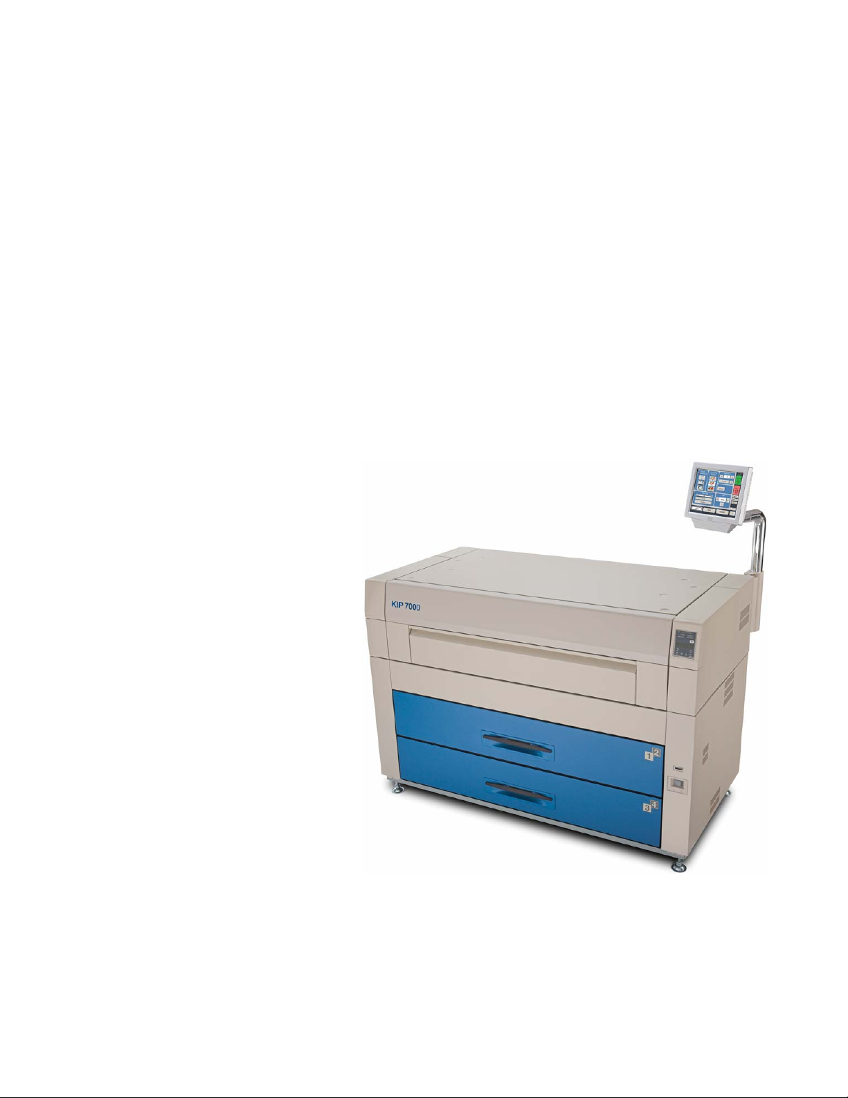
KIP 7000 - IPS
User Guide A.2
Page 2

Thank you for purchasing the KIP 7000.
This USER'S MANUAL contains functional and operational explanations for the KIP 7000.
Please read this USER'S MANUAL carefully before using the Printer.
Please keep this USER'S MANUAL for future reference.
This device complies with part 15 of the FCC Rules. Operation is subject to the following two
conditions.
(1) This device may not cause harmful interference
(2) This device must accept any interference received, including interference that may cause
undesired operation.
Do not install the Machine around other electronic equipment or other precision
instruments. Other devices may be affected by electrical noise during operation.
If the Machine is installed near other electronic equipment, such as a TV or a radio,
interference to said equipment, such as noise or flickering, may occur. Use a separate
power line and install the PRINTER as far as possible from said equipment.
As an ENERGY STAR ® Partner, Katsuragawa Electric Co., Ltd. has
determined that this product meets the
energy efficiency.
The International
promotes energy saving through the penetration of energy efficient computers and other office
equipment. The program backs the development and dissemination of products with functions that
effectively reduce energy consumption. It is an open system in which business proprietors can
participate voluntarily. The targeted products are office equipment such as computers, monitors,
printers, facsimiles, copiers, scanners, and multifunction devices. Their standards and logos are
uniform among participating nations.
ENERGY STAR ® Office Equipment Program is an international program that
ENERGY STAR ® guidelines for
(1)
Page 3
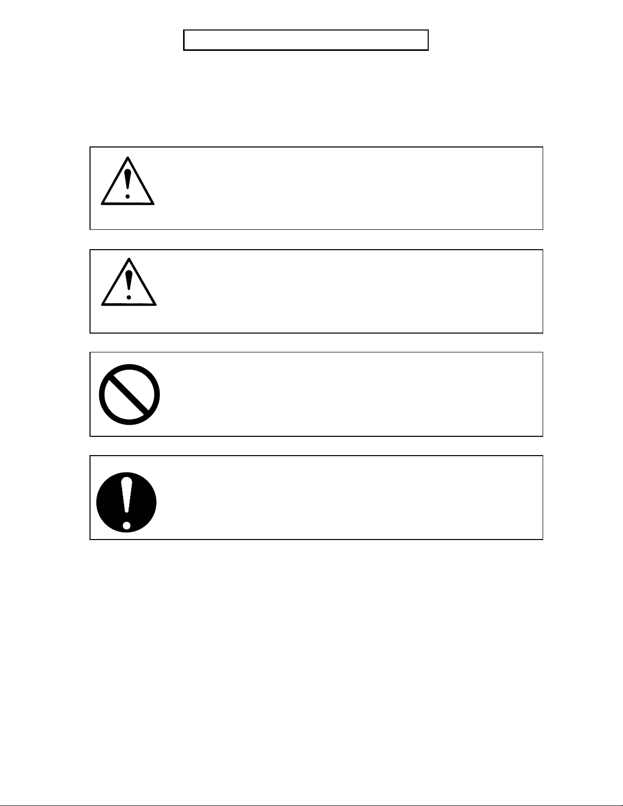
Safety Warnings
The following warnings are very important in order to safely use this product.
These notes are important in preventing danger to the operator or operation of the printer.
The following symbols are found throughout the USER’S MANUAL and have the following
meaning:
WARNING
This WARNING mark means that there is a possibility of death or serious
CAUTION
This CAUTION mark means that there is a possibility of injury or damage if
This symbol means “DO NOT ATTEMPT”
When marked with this symbol, “pay close attention to”
injury if you fail to not follow the instructions.
you fail to follow the instruction.
(2)
Page 4
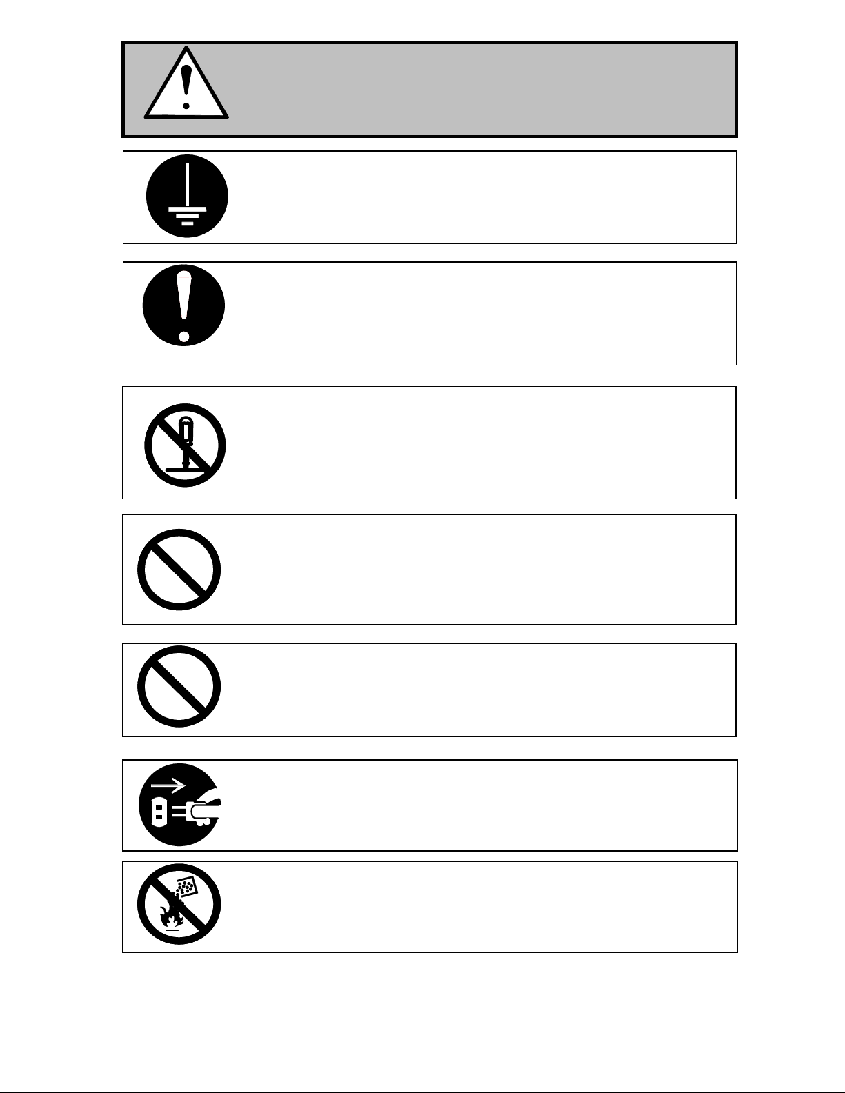
WARNING
Properly Ground the product to a ground source. Failure to do so may
1. The Power source must be as follows:
2. Use a circuit with a dedicated breaker.
3. Install the product as close to the wall outlet as possible.
4. If you wish to move the printer, please contact your service personnel.
1. Do not remove screws or open covers unless specifically instructed to
2. Do not disassemble or tamper with the printer.
Doing so may result in a fire or electric shock.
1. Do not plug in the printer into a multi-wire connector with other
2. Do not damage the Power Cord by stepping on or placing heavy items
If the product generates an abnormal smell or noise, turn it off and unplug it
Do not throw the toner or toner cartridge into a fire or other sources of heat,
result in electrical shock or damage to the equipment.
120V plus or minus 10%, 16A and 50/60Hz
do so in this User’s Manual. Failure to follow this warning may result in
electric shock, or burns.
equipment. Doing so may result in fire do to the outlet overheating.
on it. If the Power Cord is damaged, it may cause a fire or electric shock.
REPLACE THE CORD IF DAMAGED!
Do not place liquids onto the system i.e. a flower vase, a flowerpot, coffie
cup or any water-filled item on the. Spilt water may cause fire or electric
shock.
form the wall. Contact your certified service technician.
as it can explode.
(3)
Page 5
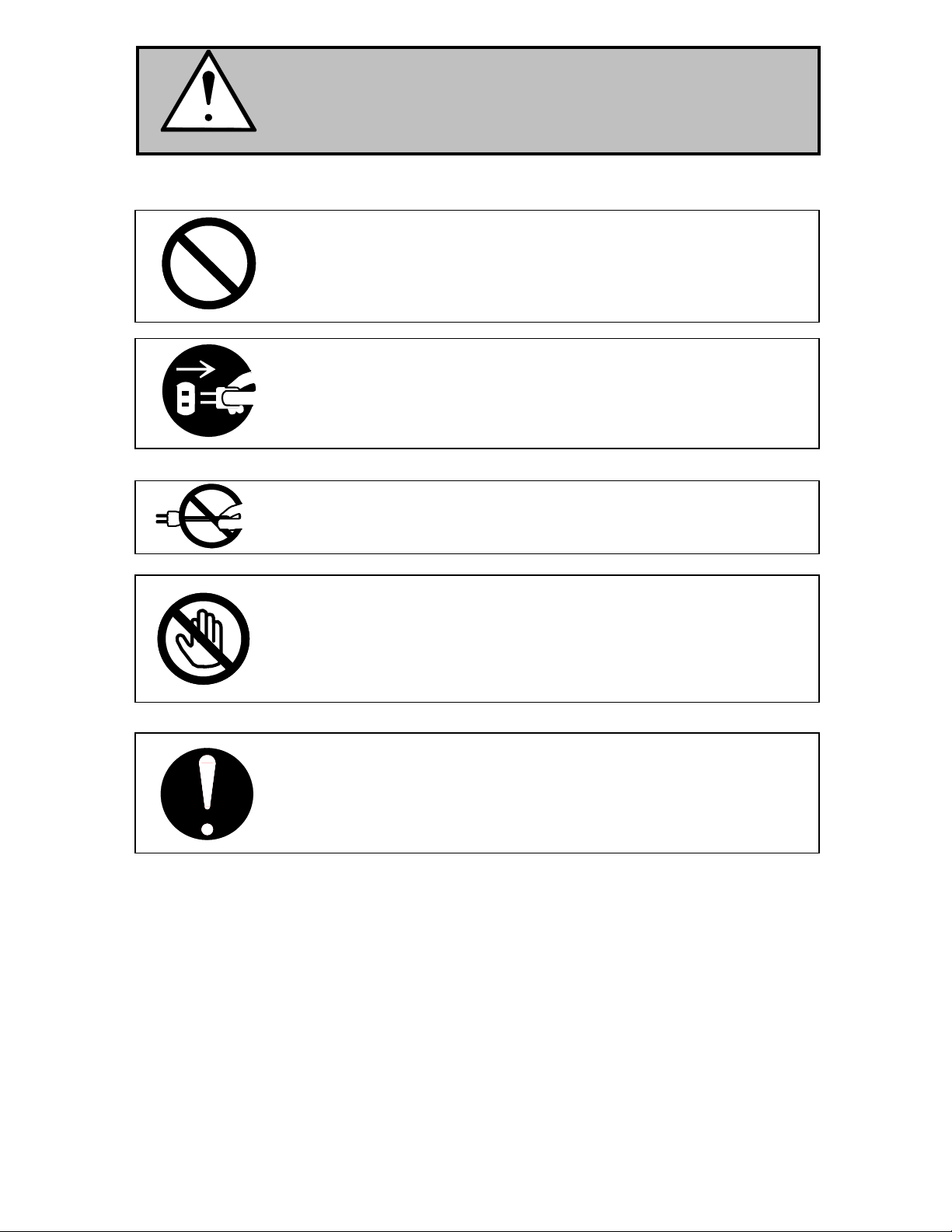
CAUTION
Do not install the printer in a humidified or dusty room.
Do not install the printer on an unstable floor as injuries may occur.
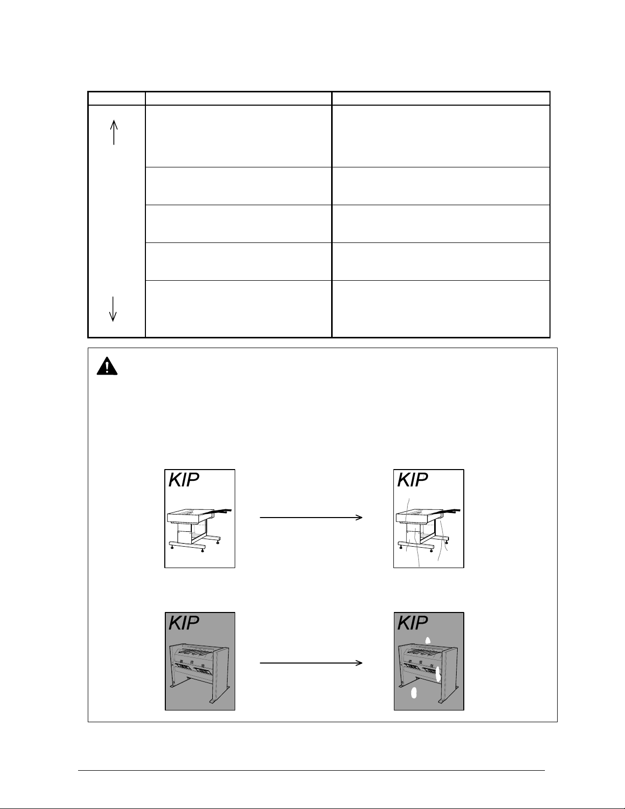
1. Unplug the printer before you move it. Failure to do so may damage to
Do not pull the cord when you unplug the printer as you may damage the
Power Cord.
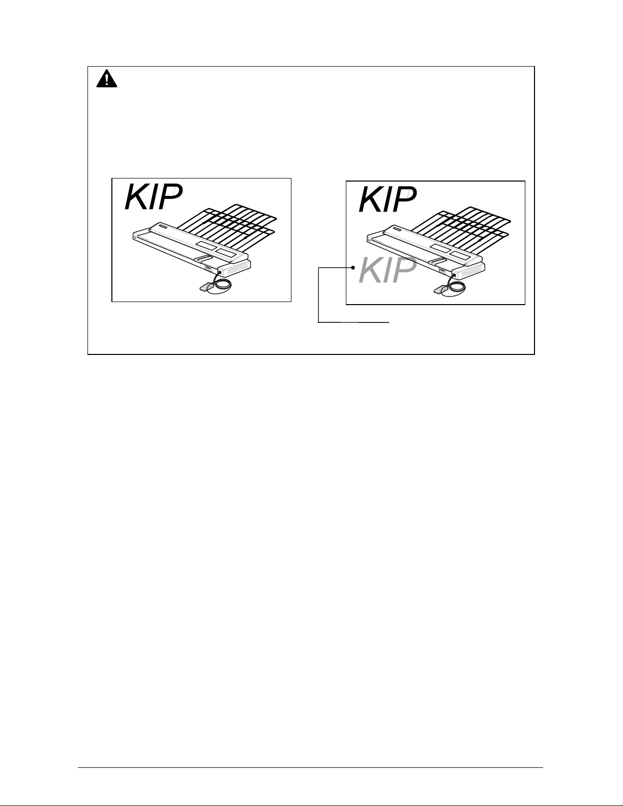
There are hot items inside of the printer.
Take great care not to touch these items when you remove mis-fed media.
Ventilate the room well if you print in a small area.
power cord resulting in fire or electric shock.
2. If the printer will be out of use for an extended period, (holidays,
company shutdown) turn off and unplug the printer from the outlet for
safety.
(4)
Page 6

TABLE OF CONTENTS
Section 1 Basic Printer Functions
Section 2 Job Info Mode
Section 3 “?” Screen
Section 4 Windows Drivers
Section 5 AutoCAD Drivers
Section 6 KIP Request
Section 7 KIP PrintNet
Section 8 Reporting
Section 9 Connectivity
(5)
Page 7

Section 1
Basic Printer Functions
1.0 Before Use 1- 3
1. 1 Installation Requirements 1- 3
1. 2 Prohibited Originals 1- 4
1. 3 Key Features 1- 5
1. 4 Specifications 1- 6
1. 5 Exterior Views 1- 7
1. 5. 1 Front view 1- 7
1. 5. 2 Rear view 1- 8
1. 5. 3 Touchscreen / Sub Display 1- 9
1. 6 Display during Normal Operation 1- 13
1. 7 Optional Configurations 1- 17
1. 8 Media Specifications 1- 18
1. 8. 1 Print Sizes 1- 18
1. 8. 2 Media not to be Used 1- 19
1. 8. 3 Maintaining the Media 1- 20
1. 8. 4 Environmental Condition – Correction 1- 21
2.0 Basic Functions 1- 23
2. 1 Turning on the Printer 1- 23
2. 2 Turning off the Printer 1- 25
2. 3 Replacing the Roll Media 1- 26
2. 4 Replacing the Toner Cartridge 1- 34
2. 5 Setting Cut Sheet Paper 1- 38
2. 6 Dehumidifying the Roll Media 1- 39
3.0 User Modes 1- 41
3. 1 Changing the Density Level 1- 41
3. 2 User Modes 1- 42
3. 2. 1 User Mode 0: (Reserved) 1- 43
3. 2. 2 User Mode 1: Image Enhancement Mode 1- 44
3. 2. 3 User Mode 2: Auto Power Off Timer Mode 1- 46
3. 2. 4 User Mode 3: Auto Power Off Mode 1- 47
3. 2. 5 User Mode 4: Cold Sleep Timer Mode 1- 48
3. 2. 6 User Mode 5: Cold Sleep Setting Mode 1- 49
3. 2. 7 User Mode 6: Warm Sleep Timer Mode 1- 50
3. 2. 8 User Mode 7: Warm Sleep Mode 1- 51
3. 2. 9 User Mode 8: (Reserved) 1- 52
3. 2.10 User Mode 9: L/L Environment Mode 1- 53
3. 2.11 User Mode A: H/H Environment Mode 1- 55
3. 2.12 User Mode b: High Coverage Mode 1- 56
3. 2.13 User Mode C: (Reserved) 1- 58
3. 2.14 User Mode d: (Reserved) 1- 58
Section 1 Basic Printer Functions 1-1
Page 8

4.0 Error Correction 1- 59
4.1 Mis-feed Errors 1- 61
4.1.1 Mis-feed in the Roll Deck Section (J-01, J-02, J-03, J-04) 1- 61
4.1.2 Mis-feed in the Manual Feeder Section (J-05) 1- 63
4.1.3 Mis-feed in the Paper Feeder Section (J-10, J-11, J-12) 1- 64
4.1.4 Mis-feed in Fuser Section (J-13, J-14) 1- 66
4.1.5 Mis-feed in Outer Device (J-21, J-22) 1- 69
4.2 Open Cover Errors 1- 70
4.2.1 Roll Deck Open (U-01, U-02) 1- 70
4.2.2 Upper Frame Unit / Top Cover Open (U-05) 1- 72
4.2.3 Exit Cover Open (U-06) 1- 73
4.3 Other Errors 1- 74
4.3.1 Toner Low 1- 74
4.3.2 Roll Empty 1- 75
4.3.3 No Manual Paper (P.E.) 1- 76
4.4 Call Service Errors 1- 77
Section 1 Basic Printer Functions 1-2
Page 9
1.0 Before Use
1. 1 Installation Requirements
The following conditions are required for installation of the equipment.
1. Power source must be rated as follows.
120V plus or minus 10%, 16A and 50/60Hz
2. The equipment must be on a dedicated circuit.
3. The outlet must be near the equipment and easily accessible.
1. Make sure to connect this equipment to a grounded outlet.
2. For PLUGGABLE EQUIPMENT, the socket-outlet must be installed near the equipment
and must be easily accessible.
Site temperature range = 50 to 89 degrees Fahrenheit; 10 to 32 degrees Centigrade
Site humidity range = 20% to 80% RH. (NON CONDENSING)
Keep the printer away from water sources, boilers, humidifiers or refrigerators.
1. The installation site must not have open flames, dust or ammonia gases.
2. The equipment must not be exposed to air vents from air conditioners; it may affect the
image quality.
3. The equipment should not be exposed to the direct sunlight. Please draw curtains to
block any sunlight. When opening the Upper Unit to remove a mis-feed, do not expose
the Photoconductive Drum to strong (intense) light as this will damage the Drum.
Ozone will be generated while this equipment is in use, although the quantity generated
is within safe levels. (see certifications) Ventilate the room, if required.
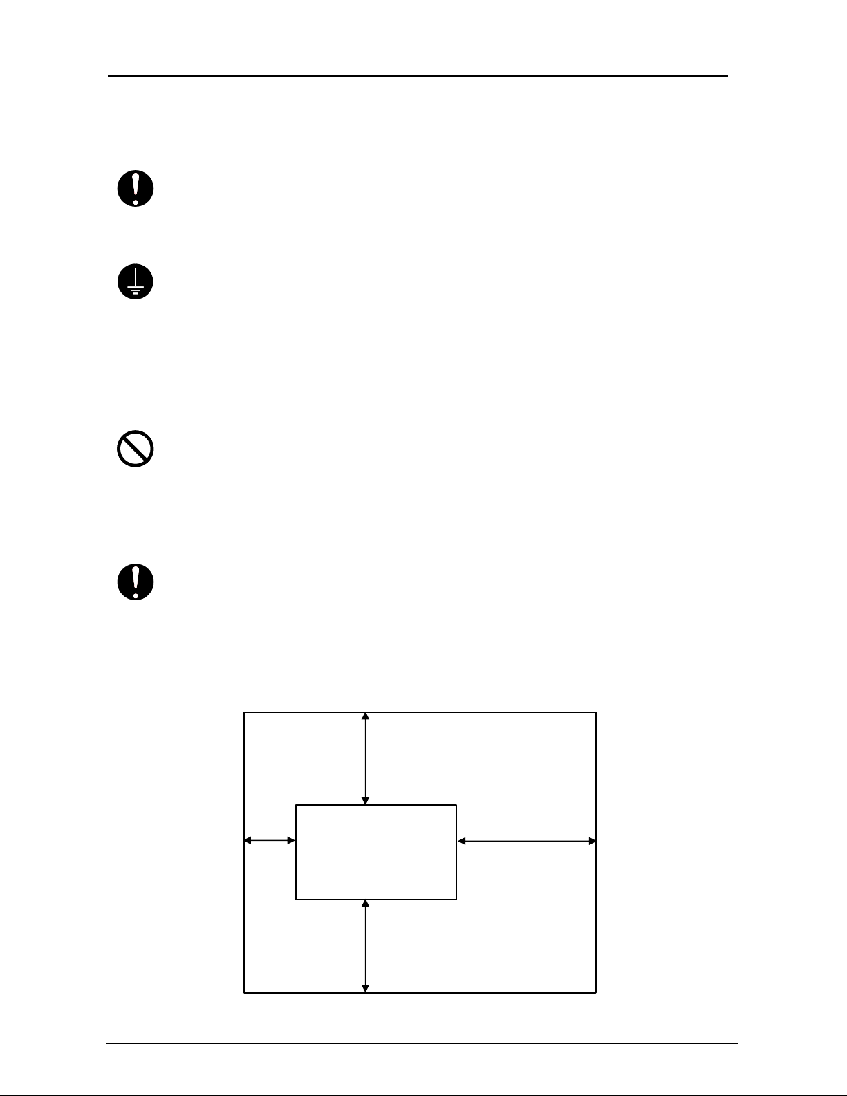
Keep ample space around the equipment to ensure comfortable operation.
(Refer to the following figure.)
The equipment must be leveled and the floor strength must be ample to sustain the
weight of the equipment.
80cm or wider
45cm 120cm or wider
or
wider
80cm or wider
Printer
Section 1 Basic Printer Functions 1-3
Page 10
1. 2 Prohibited Originals
Duplication of many documents is prohibited by law! It may be illegal to possess copies of certain
types of documents. We recommend you investigate the copyright status of documents and that
you ensure you have right to copy / scan a document prior to performing these functions.
Originals prohibited from copying / scanning (by law)
1. You cannot duplicate / copy Currency (Bill, Money, Bank Note, etc.), Government issued
Negotiable Instruments (National Bonds, Security, Local Debt Bonds, etc.).
2. You cannot duplicate / copy Foreign Currency or Foreign Negotiable Instruments.
3. You cannot duplicate / copy unused postal stamps or government postcards without
permission to replicate from the Government.
4. You cannot duplicate/copy Government issued revenue stamps or certificate stamps, which
are issued by the Liquor Tax Acts or the Commodity Tax Acts.
Other Notable Items
1. You are warned by the government not to copy / scan, private issued securities (stock
certificate, draft, check, goods ticket, etc.), commutation ticket or book of tickets, excluding
that some specific companies can copy such originals it requires for their own business.
2. We recommend you not freely copy / scan government issued passports, public or private
issued licenses, automobile inspection certifications, ID and tickets (passes or meal).
Law To Reference Items Prohibited to Duplicate
Regulations to control fake currency and
bonds.
Control Law against Forged or Fake
Foreign Currency, Bill, Bank Note and Bond
Forged postal stamps control law Unused postal stamps or government postcards
Forged revenue stamp control law Government issued revenue stamps, and
Currency similarity securities Control Law Private issued securities (stock, draft, check,
Originals protected by Copyright
It is prohibited to copy / scan:
books, music, paintings, maps, drawings, movies and pictures which are protected by
copyright.
Currency (Bill, Money, Bank Note, etc.),
Government issued Negotiable Instruments
(National Bonds, Security, Local Debt Bonds,
etc.)
Foreign Currency or Foreign Negotiable
Instruments
certificate stamps prescribed by Liquor Tax Act
or Commodity Tax Act
goods ticket, etc.), commutation or book tickets
Section 1 Basic Printer Functions 1-4
Page 11

1. 3 Key Features
The KIP 7000 is a single or dual footprint system which can print, copy and scan with an optional
scanner. Advanced drivers and comprehensive print utilities make the KIP 7000 an advanced, easy
to use system. Please note that some functions may be optional.
The print speeds are up to 160mm/sec or up to 13 landscape “D” prints/minute.
KIP HDP technology generates no waste toner.
The combination of the KIP HDP Plus imaging system with mono-component minute toner
produces high definition lines, distinctive grayscale and consistent blacks.
The maximum paper width is 914mm or 36” wide, and the minimum is 279mm or 11”.The maximum
paper length is 6m or 19.7 ft and the minimum is 210mm or 8.5”.
Up to 600dpi print, copy and scan resolutions, with an advanced Image Process System, produces
the highest quality images.
Network Printer Features
• Standard TCP/IP connectivity
• Direct support for vector file formats: HPGL1/2, HP-RTL, Calcomp 906/907
• KIP DWF format support
• Direct support for raster file formats: TIF Group 3/4, Cals Group 4, Uncompressed
Grayscale/Color TIF,
• Optional KIP PDF format support: PS/PDF file format.
• Standard Windows Driver for KIP Script (PS output) and KIP-GL (HPGL/2,RTL output)
• Standard AutoCAD Drivers
• Unlimited site license of KIP Request allows users to group supported formats together
for printing collated sets.
• Integrated Accounting in all KIP Drivers/Request for all network printing.
• Integrated KIP Web Printing (web server)
• Open architecture ASCII Job Ticket for third party applications
Copier Features (Optional)
• Easy Touch screen control panel
• Collated Sets copying
• Real-time image preview
• Recall/reprint previous jobs
• 600x600DPI copy quality
• Integrated Accounting and Reports for all copying, network printing, scanning
• Network ready copier
• Simple Operator assistance for every day tasks (toner replacement procedure)
• Image stamping
• Information center displays all support information, meter readings, and serial number.
• Color copy to third party color wide format inkjet devices (Optional)
Scan-to-File Features (Optional)
• Scan directly to PDF, TIF Group 4, Cals Group 4
• Scan to file to FTP, LAN location or personal inbox on the KIP
• Selected resolution – up to 600 DPI optical
• Automatic original size recognition
• Retrieve scanned image files with KIP Request
• Scan to color (Optional)
Section 1 Basic Printer Functions 1-5
Page 12
1. 4 Specifications
Subject Specification
Model KIP 7000
Configuration Console
Printing method Electrophotography
Photoconductor Organic Photoconductive Drum
Print speed 160mm per second (13 D or 7 sheets of A0 per minute)
Print head LED
Resolution 600dpi
Print width Maximum width 914mm (36 inches)
Minimum width 210mm(cut sheet) / 11inches (Roll Paper)
Print length Maximum length 6m 19.7’ ft (Standard)
24m or unlimited (Optional)
Minimum length 210 or 8.5” mm
NOTE : If the print is longer than 6m, image quality or the reliability
of media feeding systems is not guaranteed
Warm up time Less than 6 minutes (At 23 degrees Centigrade, 60% RH and the
rated voltage/Plain Paper)
First print time 15.5 seconds (A0 or E print from Roll 1)
Fusing method Roll Fuser
Development method Dry type with non-magnetic mono-component toner
Exposure method LED
Charging method Corona
Transfer method Corona
Separation method Corona
Input power 220V - 240V plus 6% or minus 10%, 50/60Hz, 16A
Average power
consumption
230V, 50/60Hz and Dehumidify Heater is ON
Stand by 1.0kwh
Printing 2.6kwh
Acoustic noise Less than 67db (Printing)
Less than 55db (Stand by)
Ozone Smaller than 0.1ppm (Average)
Dimensions 1385mm (Width) x 810mm (Depth) x 1590mm (Height)
( 55” x 32” x 63” ) (without Tray)
Weight Approx. 370kg or 815 lbs
Media (Recommended Media)
Plain Paper US Bond (20lbs)
Tracing Paper US Vellum (20lbs)
Film 4MIL
Environmental condition
for usage
Interface Hi-Speed (LVDS) I/F VIII interface
NOTE 1: The above specifications may change without notice.
NOTE 2: <Storage condition of consumables>
Media Wrap the media surely to shut out the humidity.
Toner Keep the toner cartridge away from the direct sunlight, and store it
in the condition of 0 to 35 degrees Centigrade and 10 to 85% RH.
(Temperature)
10 to 32 degrees Centigrade
50 to 89 F
(Humidity)
20 to 85% RH
Section 1 Basic Printer Functions 1-6
Page 13
1. 5 Exterior Views
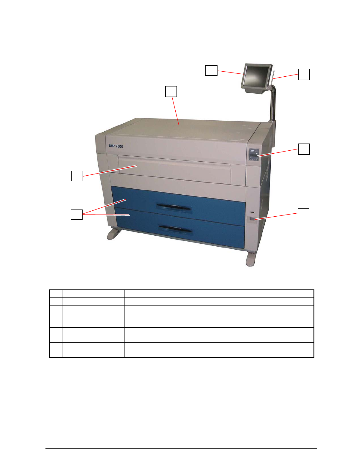
1. 5. 1 Front view
Name of part Function
1 User Interface (UI) This is a Touch Screen, and many user operations are available.
2 Top Cover Open to clear the mis-fed paper.
3 Manual Table Open to insert a sheet of paper, or to pull the Upper Frame Unit.
4 Roll Decks Each Roll Deck holds 2 rolls of print media.
5 Sub Display Panel Printer information and error codes are indicated on this panel.
6 Power Switch Press “ON” to turn on the printer, and press “OFF” to turn it off.
7 Pen This pen is used to operate the User Interface (UI).
3
4
It is possible to put KIP 600 Scanner and KIP 2100 Scanner.
2
1
7
5
6
Section 1 Basic Printer Functions 1-7
Page 14
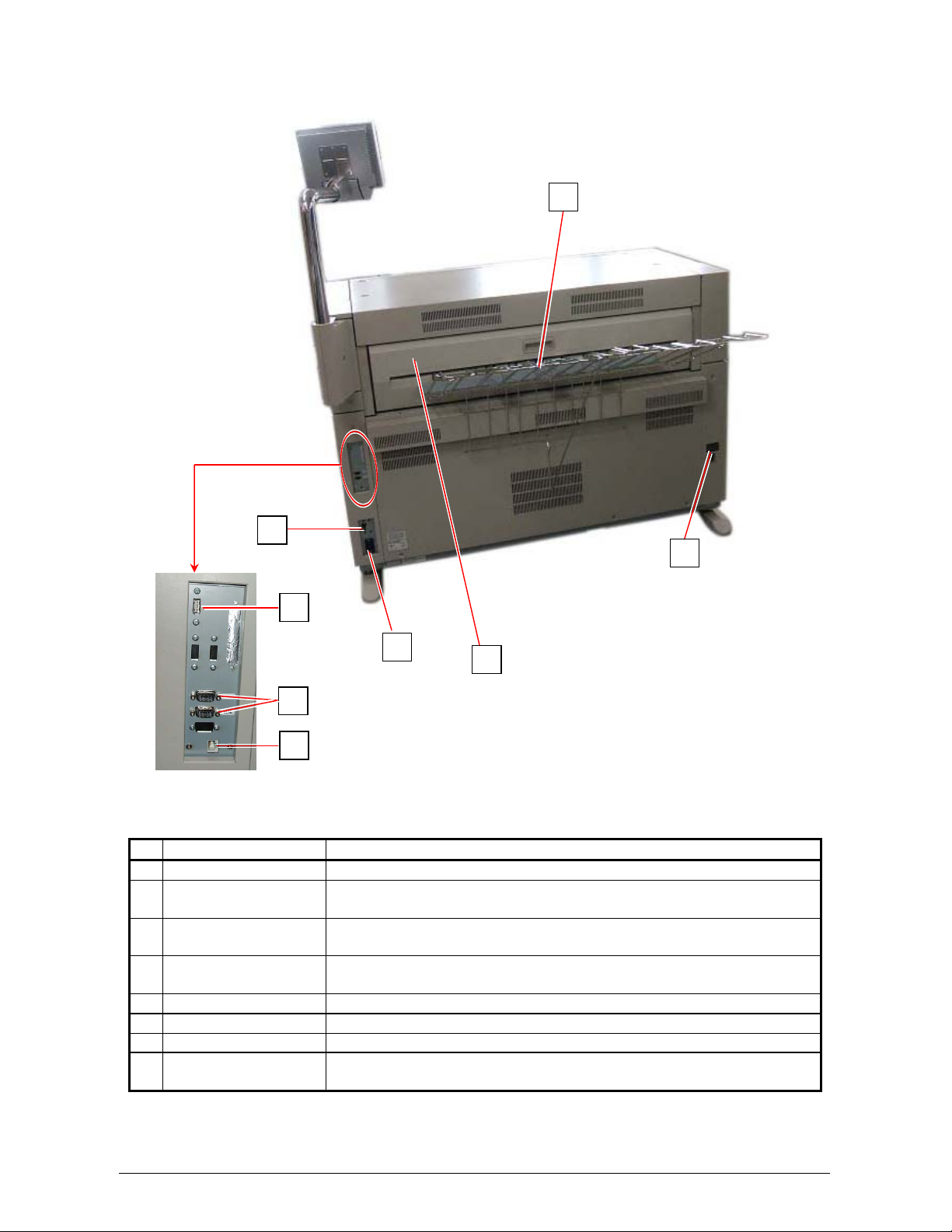
1. 5. 2 Rear view
Name of part Function
1 Tray Prints are stacked here after the ejection.
2 USB connector
(USB2.0)
3 COM Port Connect the cable from the Optional Device.
4 LAN Port Connect the LAN Cable to connect the KIP 7000 to the network.
5 Breaker It is possible to shut off supplying the AC power.
6 Inlet Socket Connect the Power Cord here.
7 Exit Cover Open the Exit Cover when you remove the mis-fed media.
8 Dehumidify Heater
Switch
5
2
6
7
3
4
Connect the cable to this terminal, which is included with the KIP
600 and KIP 2100. (max.5Vdc)
(D-Sub Connector 9 pins: max.12Vdc (Small))
(Do not connect a telephone line.)
Press “H” to turn on the Dehumidify Heater, and press “L” to turn it
off.
1
8
Section 1 Basic Printer Functions 1-8
Page 15
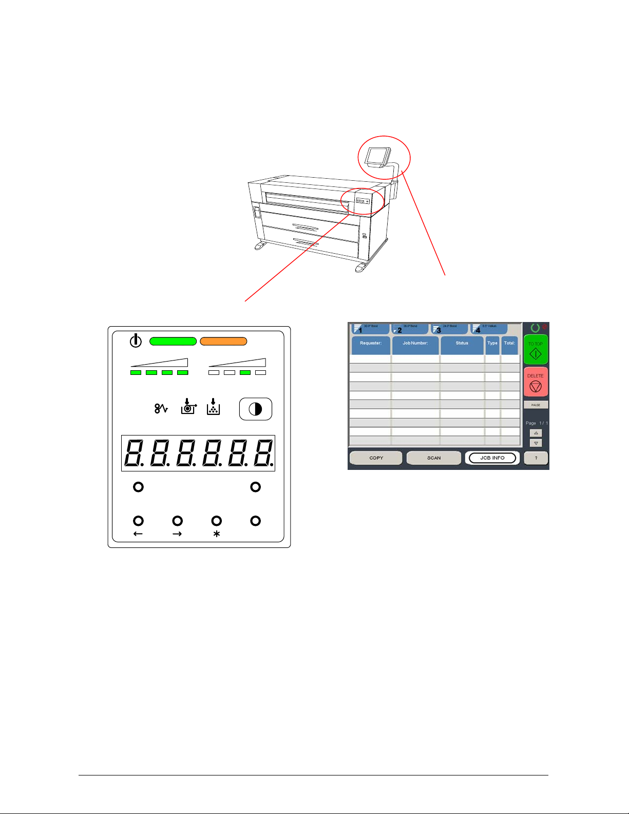
1. 5. 3 Touchscreen / Sub Display Panel
There is a Touchscreen and a Sub Display Panel on the printer.
Some functions on the Touchscreen are also displayed on the Panel.
Refer to the following page for indicators and basic functions of the Operation Panel / Touchscreen.
Sub Display Panel
Touchscreen
TONER REMAIN IMAGE DENSI TY
job
MENU TEST
ENTER
The following pages only contain notes on the “Job Info” screen which
is used in a printer only configuration.
Other menus or screens may also be accessible but are detailed in other
User Guides. Other screens may be included in alternative options of the
KIP 7000.
Section 1 Basic Printer Functions 1-9
Page 16
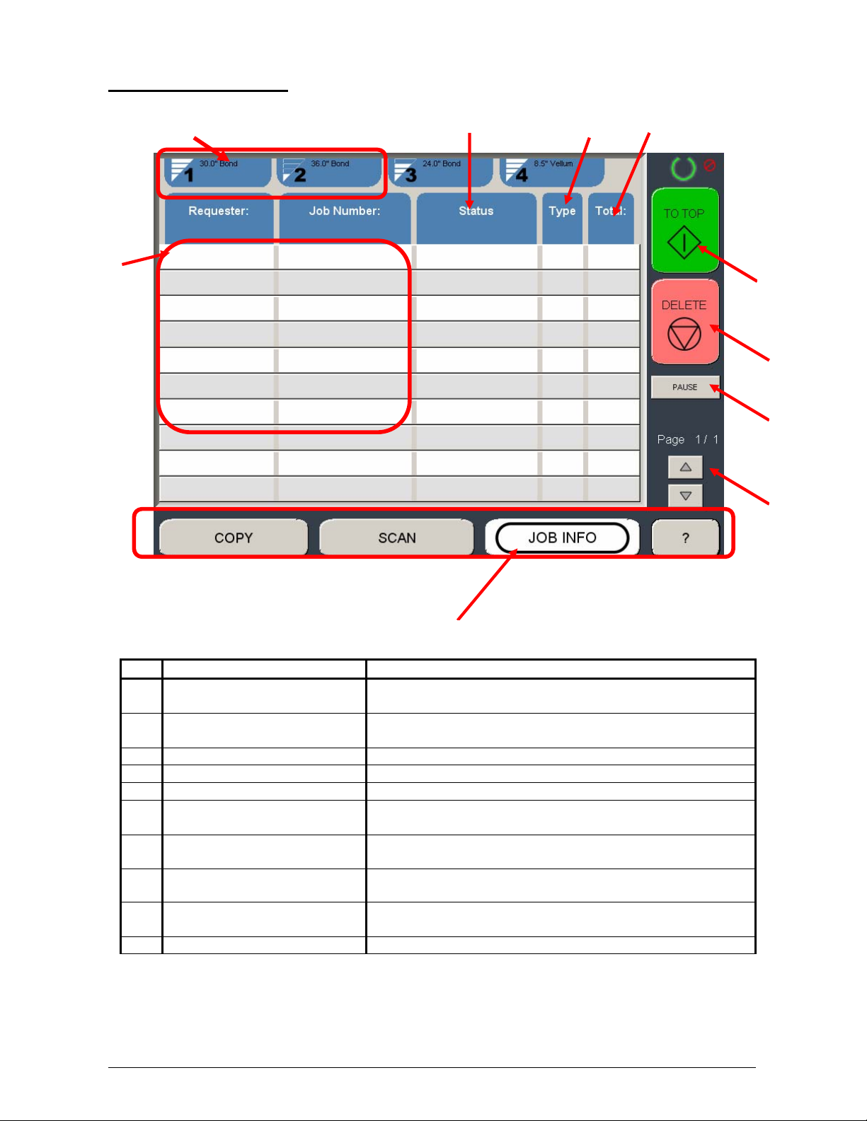
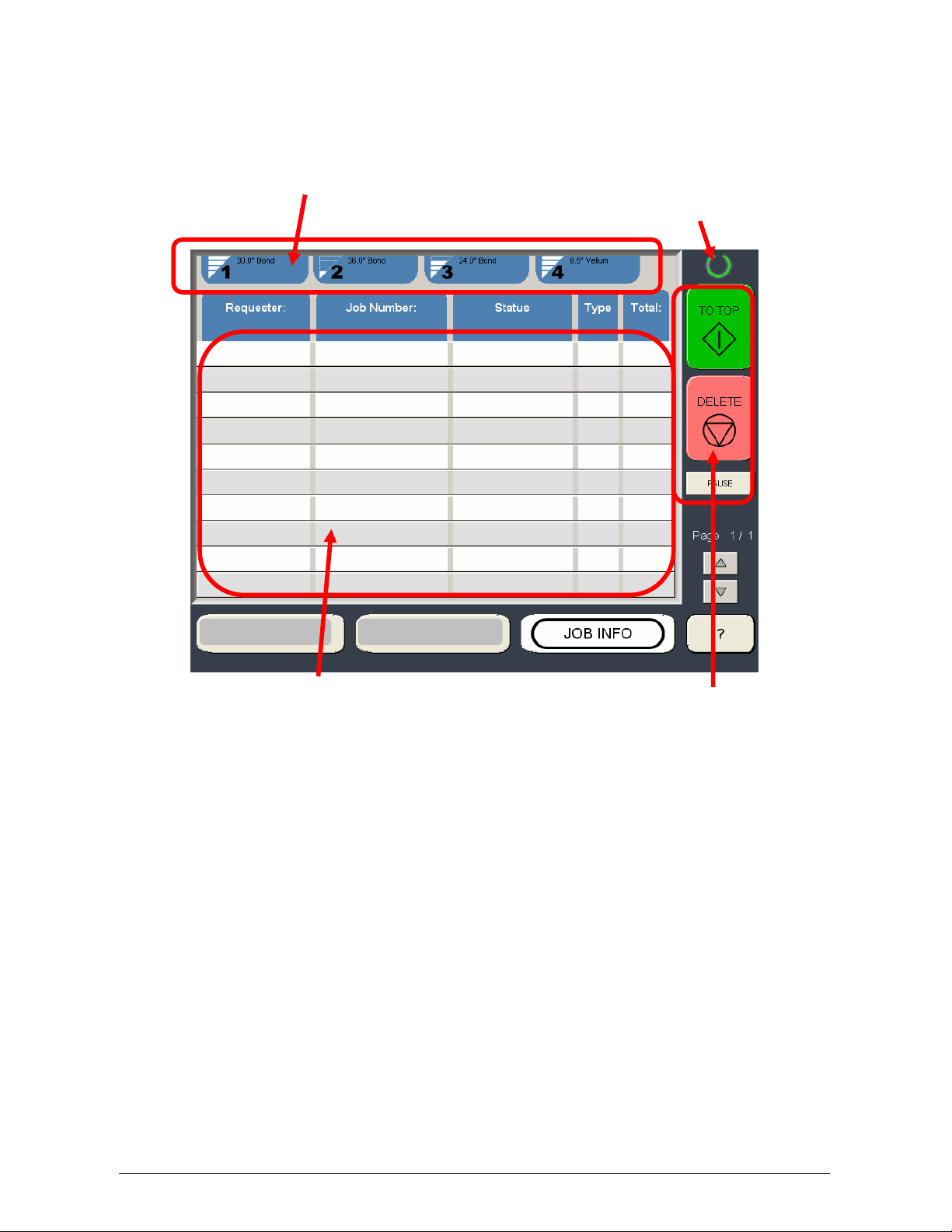
Job Info Screen
2
No. Name Function
1 Mode Selects the “Mode” of the system. (Job Mode for this
2 User Name – Job # Display the User and any user info of the job ID. A job
3 Media Information Displays Width, Type and amount remaining per roll deck
4 Status Shows the current status of a job and media selection.
5 Type Displays a copy or network print job
6 Total Displays the total number of prints and current number
7 To Top After a job is selected (see #2) its position in the queue
8 Pause Pauses printer to allow media change, etc
3
screen shown)
can be selected for other functions noted below.
printed.
can be changed, making it the next job printed.
4 5 6
1
7
8
9
10
9 Delete After a job is selected (see #2) it can be removed from
the print queue.
10 Up/Down Scrolls through pages in the queue if so available.
Section 1 Basic Printer Functions 1-10
Page 17
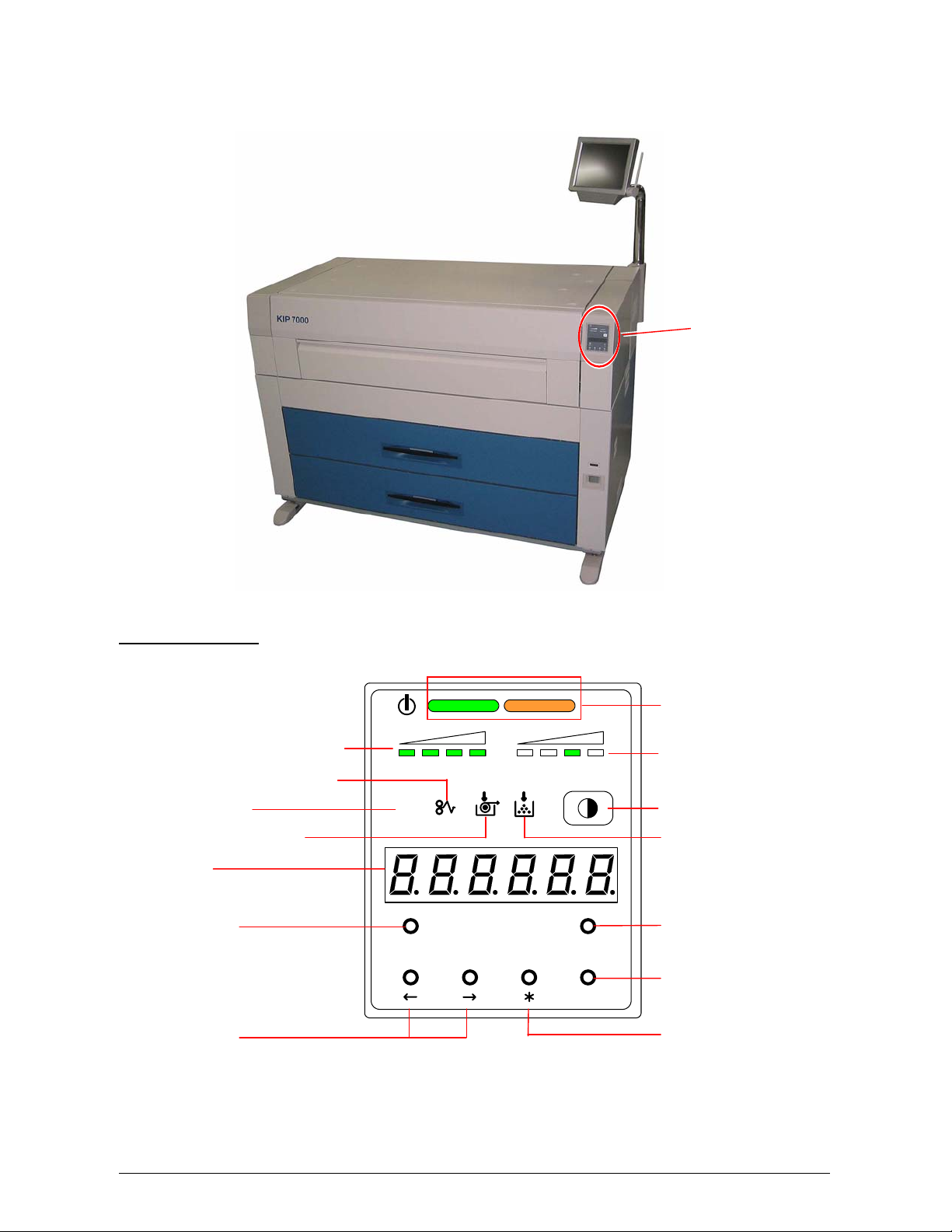
There is a Sub Display Panel on the top of the printer.
Refer to the following page for indicators and key functions.
Sub Display Panel
Toner Remaining Indicator
Paper Mis-feed Indicator
Job Indicator
Roll Empty Indicator
Display
TONER REMAIN IMAGE DENSI TY
job
Menu Key
MENU TEST
Arrow Keys
Sub Display Panel
Status Indicator
Image Density Indicator
Density Selection Key
Toner Low Indicator
Test Print Switch
Enter Key
ENTER
* (Asterisk) Key
Section 1 Basic Printer Functions 1-11
Page 18
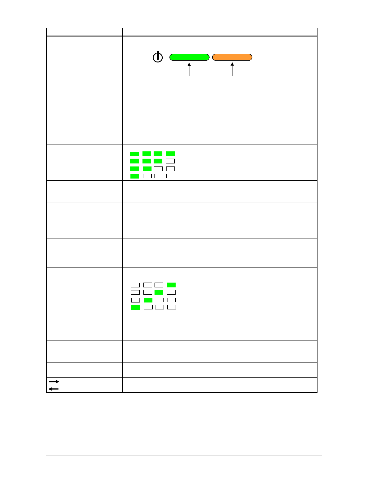
Name of part Function
Status Indicator
OFF : Power is not supplied.
Lighting Orange : Warming up/printing is prohibited.
Flashing Orange : Sleep Mode
Flashing Green : Temperature Recovering Mode
(Printing is temporarily interrupted to recover
the temperature of Fuser Unit.)
Lighting Green : Ready/Printing
Toner Remaining
Indicator
Paper Mis-feed Indicator Paper Mis-feed Indicator lights red when the printer or optional
Job Indicator Job Indicator lights green when the printer receives a print job from
Roll Empty Indicator Roll Empty Indicator lights red when the roll media in the selected
Display The Display normally shows green which Roll Deck is selected and
Image Density Indicator Image Density is indicated green with every 1/4 step.
Density Selection Key You may change the density level by pressing the Density Selection
Toner Low Indicator Toner Low Indicator lights red when there is not enough toner in the
Menu Key Menu selection ( User Mode )
Test Print Switch A test pattern will be printed out if you press the Test Print Switch.
Enter Key Selected job is defined. (User Mode)
* (Asterisk) Key Function selection ( User Mode )
(Right Arrow) Key Mode selection (Increment) ( User Mode )
(Left Arrow) Key Mode selection (Decrement) ( User Mode )
Toner Remaining Volume is indicated green with every 1/4 step.
: Toner remains more than 3/4.
: Toner remains more than 2/4.
: Toner remains more than 1/4.
: Toner remains less than 1/4.
device fails to feed the media.
A mis-feed code is indicated on the Display if this occurs.
the scanner or controller.
Roll Deck is empty.
It also lights when the roll media is not correctly installed.
the width of the roll media in said Roll Deck.
It also indicates an error code if the printer has an error such as
“paper mis-feed” or “door open”.
(Strobe time is adjusted.)
: Darker
: Normal
: Lighter
: Lightest
Key.
Developer Unit.
(Service purpose only.)
Green
Orange
Section 1 Basic Printer Functions 1-12
Page 19
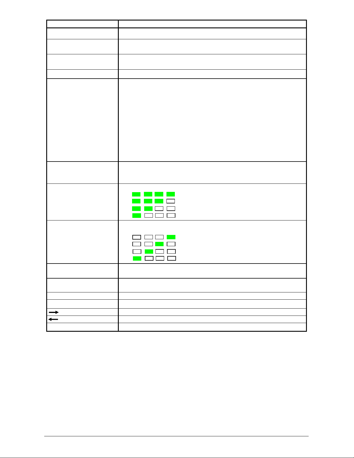
Name of part Functiom
Toner Low Indicator Lights when toner is required.
Roll Empty Indicator Lights when the roll media in the selected Roll Deck is empty. It can
also light when the media is not correctly installed.
Paper Mis-feed Indicator Lights when the printer or optional device fails to feed the media. A
mis-feed code is indicated on the Display if this occurs.
Job Indicator Lights when the printer receives a job
Ready Indicator OFF : Power is off.
Lighting RED : Warming up / Printing is prohibited.
Flashing RED : The printer is in the Warm Sleep Mode.
(Quick Flash) (For Information on Warm Sleep Mode, refer to
pages 3-11 to 3-12.)
Flashing RED : The printer is in the Cold Sleep Mode.
(Normal Flash) (For Information on Cold Sleep Mode, refer to
pages 3-9 to 3-10.)
Lighting GREEN : Ready / Printing.
Flashing GREEN : Temperature Recovering Mode
(Printing is temporarily interrupted to recover the
temperature of Fuser Unit.)
Display It indicates the selected Roll Deck and the width of the roll media in
the selected Roll Deck. It also indicates an error code if the printer
has an error such as “paper mis-feed” or “door open”.
Toner Remaining
Indicator
Image Density Indicator Image Density is indicated in 1/4 steps.
Density Selection Key You may change the density level by pressing the Density Selection
Test Print Switch A test pattern will be printed out if you press the Test Print Switch.
Enter Key Selected job is defined. (User Mode)
* (Asterisk) Key Function selection (User Mode)
(Right Arrow) Key Mode selection (Increment) (User Mode )
(Left Arrow) Key Mode selection (Decrement) (User Mode)
Menu Key Menu selection (User Mode)
Toner Remaining Quantity is indicated in 1/4 steps.
: Toner remains more than 3/4.
: Toner remains more than 2/4.
: Toner remains more than 1/4.
: Toner remains less than 1/4.
: : Darker
: Normal
: Lighter
: Lightest
Key. (please also see the Touchscreen “?” “Configuration”)
(Service purposes only.)
Section 1 Basic Printer Functions 1-13
Page 20
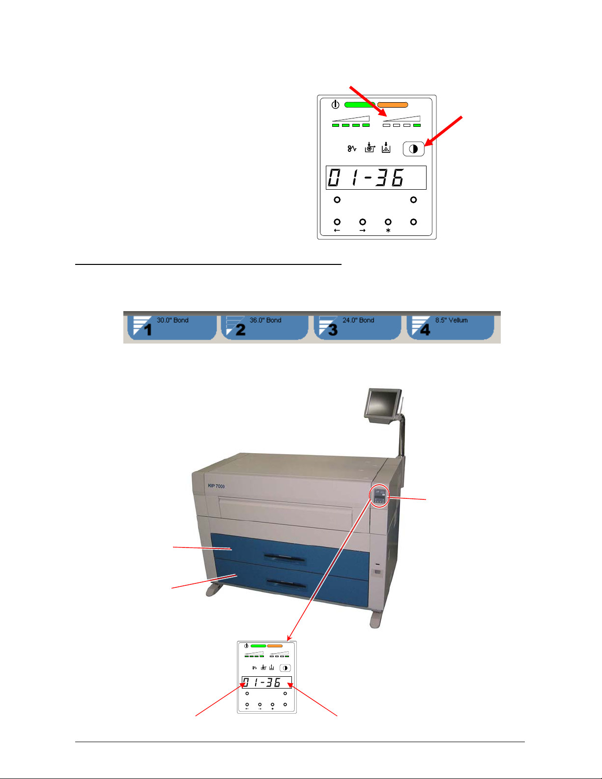
1. 6 Display during Normal Operation
The following default screen appears on the touchscreen if the system is only a network printer.
Please see other chapters for copy, scan and “?” modes.
Roll number, media type and remaining quantity Printer is ready when solid green,
warming when flashing
All jobs displayed here with current status and can be moved or deleted.
As well as the touchscreen, there is a Sub Display Panel that indicates the following information
during normal use of the printer. The key functions of the SUB Display Panel are service functions.
Please perform the user functions on the Touchscreen.
Section 1 Basic Printer Functions 1-14
Page 21
(1) Processing a print
On the Touchscreen all jobs or prints will be listed as well as the status:
List Status
On The Sub Display Panel
The Job Indicator lights when the printer receives a job.
TONER REMAI N IMAGE DENSITY
job
MENU TEST
ENTER
(2) Image Density level
Please also see the Touchscreen “?” screen, Configuration Menu, Page 1 for this setting.
Section 1 Basic Printer Functions 1-15
Page 22
The user can also adjust the density on the printer. Any of the 4 LED’s of the Image Density
Indicator will light according to the density level you selected. Image density becomes darker when
you select LED’s further to the right.
TONER REMAIN IMAGE DENSITY
job
MENU TEST
ENTER
(3) Roll Deck, the roll width and roll material currently used
The touchscreen will display the currently installed and configured media on the top of the Job Info
Screen.
The display on the Sub Display Panel only indicates the current Deck Number and the media
width. Before printing or copying, you can select which roll media to use from the workstation or the
copier user interface.
Sub Display Panel
Roll 1 (Front)
Roll 2 (Rear)
Roll 3 (Front)
Roll 4 (Rear)
TONER REMAIN IMAGE DE NSITY
job
MENU TEST
ENTER
Roll Deck No. Paper Width
Section 1 Basic Printer Functions 1-16
Page 23

1. 7 Optional Configurations
Standard configuration of the KIP is Network Printing. Print via TCP/IP from Windows and CAD
applications. Included: Windows/PS drivers, AutoDesk Drivers, “KIP Request” job submission utility
and “KIP PrintNet” for web based submissions.
Please contact your Authorized KIP Dealer for the following options available for the KIP :
1) Mono Copy
2) Mono Scan
3) KIP Production Station Software - Dual Footprint
4) Simple Color Copy / Scan
5) Advanced Color Copy / Scan - Dual Footprint
6) PDF / PS Printing
7) Print Tray - Stacker KIP 1000
8) Print Tray - KIP 1200
9) Folding (KIPFold)
All KIP options and accessories are subject to change without notice. Please contact your local
Authorized Reseller for details on current available options for the KIP .
Section 1 Basic Printer Functions 1-17
Page 24
1. 8 Media Specifications
1. 8. 1 Print Sizes
Available print sizes are as follows:
Minimum Maximum
Width 11 inches (Roll Paper)
8.5 inches (Cut Sheet paper)
Length 8.5 inches 19.7 ft
NOTE
It is possible to print longer than 19.7 ft ( 6 m) as an option. You can choose either “24m” or
“unlimited” as a maximum print length. Call your service personnel if you would like to print
over 6meters as the user can not change this setting in the printer.
If you print longer than 19.7 ft or 6 meters, the image quality or the reliability of media
feeding is not guaranteed.
36 inches
Section 1 Basic Printer Functions 1-18
Page 25
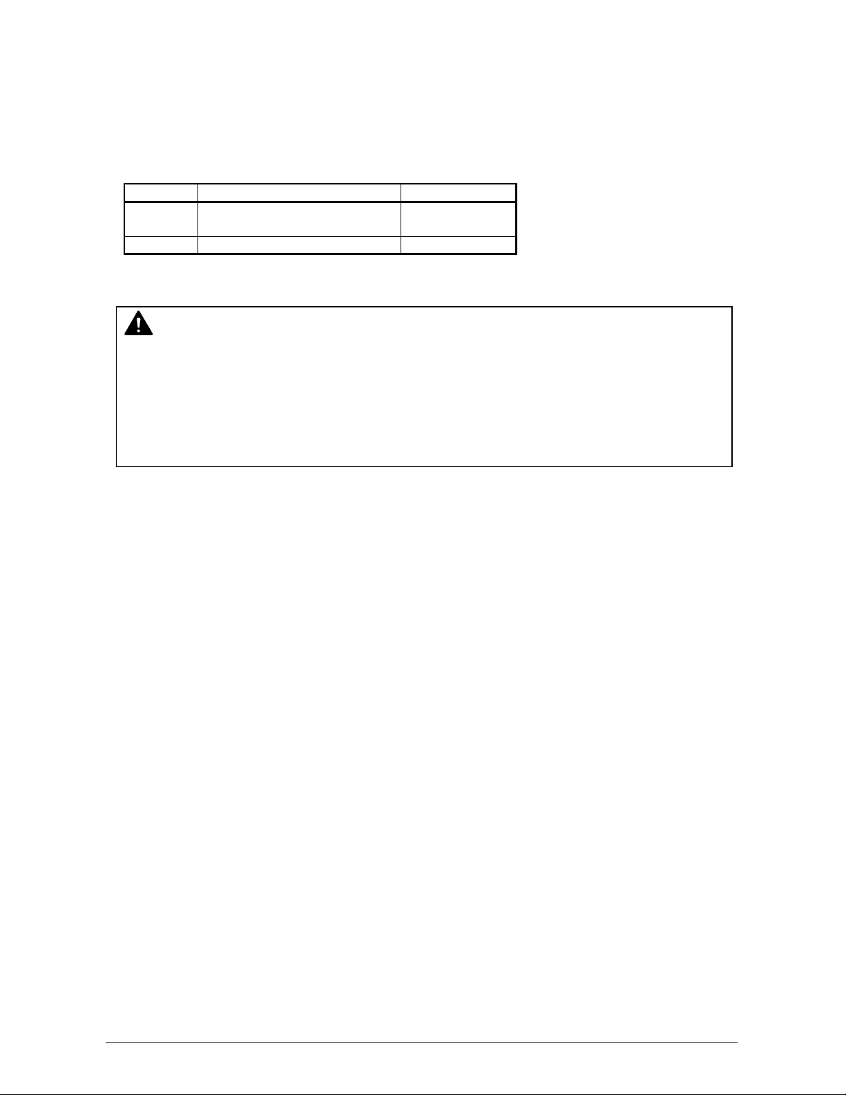
1. 8. 2 Media not to be used
Do not use the following kinds of printing paper. Doing so may damage the printer.
Excessively curled
Folded
Creased
Torn
Punched
Section 1 Basic Printer Functions 1-19
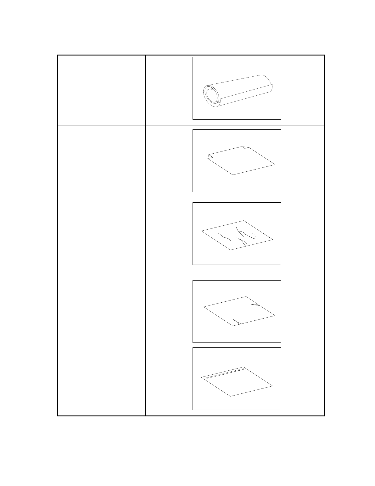
Page 26
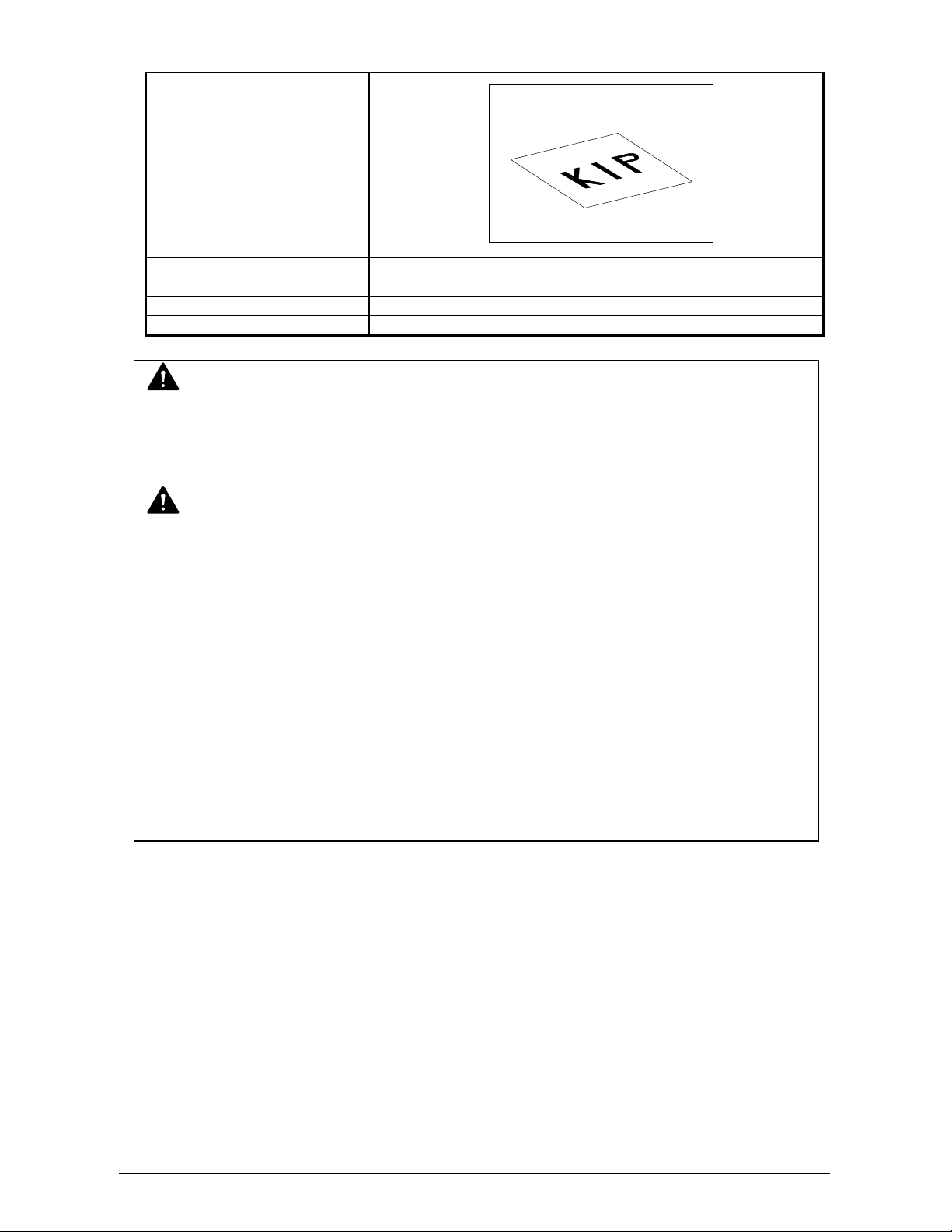
Pre-printed
Extremely slippery
Extremely sticky
Extremely thin and soft
OHP Film
CAUTION
Do not use paper with staples.
Do not use such conductive paper such as aluminium foil and carbon paper.
The above may result in fire or damage to the machine.
NOTE
(1) Print image may become light if printed on the rough surface of the paper.
(2) Print image may be poor if the print paper has excess curl.
(3) Using paper that does not satisfy the specifications may cause paper mis-feeds, poor
print images, or creasing.
(4) Do not use paper with “unique” surfaces, such as thermal paper, art paper, aluminium
foil, carbon paper and conductive paper.
(5) Vellum that is exposed to air over a long period of time tends to cause poor printing. We
recommend you that you remove one round on the surface of the vellum by using the
Initial Cut Key on the User Interface (UI).
(6) Remove all adhesive from the media roll that may remain from tape placed onto the
media by the media supplier.
1. 8. 3 Maintaining the Media
Store the media noting the following:
1. Do not expose the paper to the direct sunlight.
2. Keep the paper away from high humidity. (It must be stored at less than 70%)
3. Put the paper on a flat surface, do not damage the media.
4. If you will store paper that has already been unpacked, put it into a plastic bag to avoid
moisture in the media.
Section 1 Basic Printer Functions 1-20
Page 27
1. 8. 4 Environmental Condition - Correction
Take the necessary actions according to the environmental condition as shown below.
Humidity(%)
Low
40%
70%
High
NOTE
(1) KIP5000 is equipped with a Dehumidify Heater.
Using it in high humidity environment (65% or higher) is recommended.
(2) “Voids” and “creasing” will occur in case of extremely high or low humidity.
Possible problem Necessary treatment
“Void of image”, “crease of paper”
and other problems occurs when you
print.
“Void of image” occurs when you
print with vellum.
“Void of image” occurs when you
print with plain paper and vellum.
“Void of image”, “crease of paper”
and other problems occurs when you
print
Normal Print
If the media is humidified
Normal Print
If the media is humidified
1. Install a humidifier in the room, and
humidify the air.
2. Remove the media from the machine
immediately after the printing, and keep it
in a polyethylene bag.
When not using it, remove the vellum from
the machine and keep it in a polyethylene
bag.
Remove the paper from the machine after
everyday use, and keep it in a polyethylene
bag.
When not using it, remove the media from
the machine and keep it in a polyethylene
bag.
1. Turn on the Dehumidify Heater.
2. Remove the media from the machine
immediately after the completion of print,
and keep it in a polyethylene bag.
Crease
Void
Section 1 Basic Printer Functions 1-21
Page 28
NOTE
(3) Re-appearance of image (especially solid black images) may occur if you print with a
humidified film.
When film is installed in a high humidity environment (higher than 60%RH), we
recommend that you turn on the Dehumidify Heater.
Normal print Re-appeared image
Section 1 Basic Printer Functions 1-22
Page 29
2. 0 Basic Functions
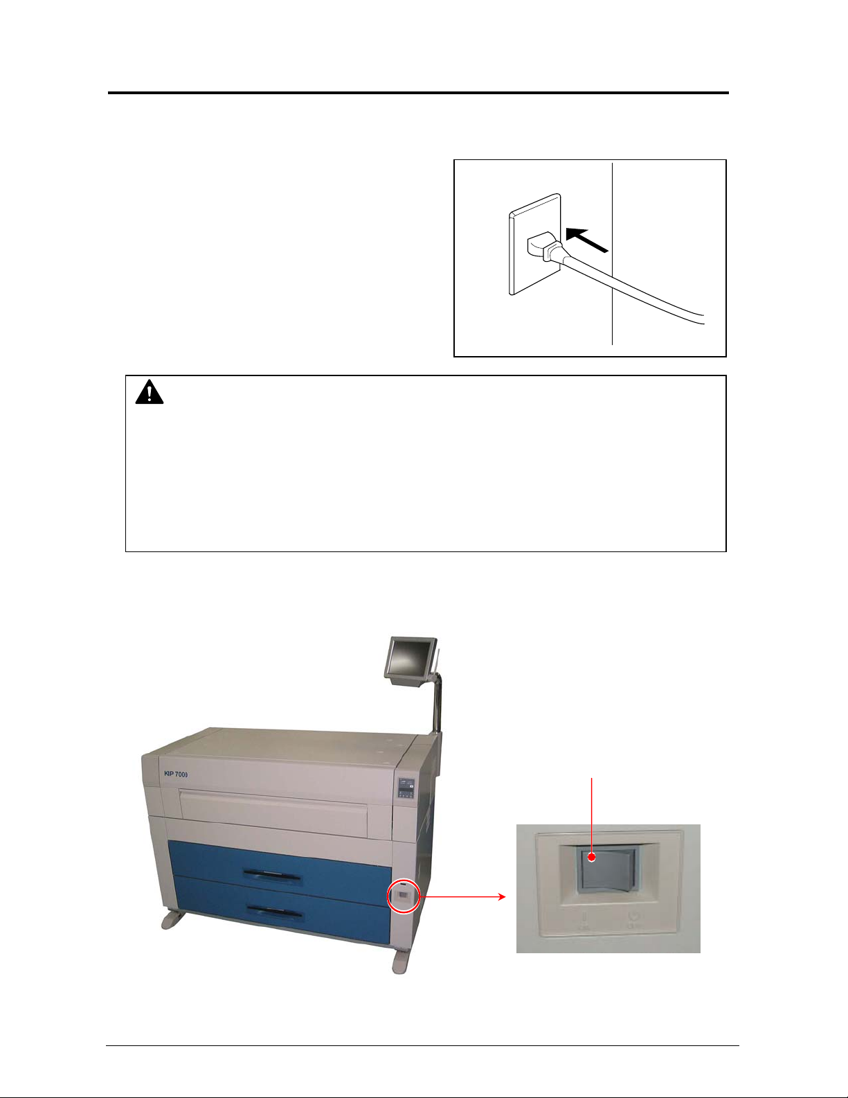
2. 1 Turning on the Printer
1) Plug the printer into an exclusive wall outlet.
WARNING
(1) Ground the printer for safety.
(2) Do not plug the printer into a multi-wiring connector. It may cause the outlet to overheat
2) There is a Power Switch (A) on the right-front of KIP 7000.
Press “ON” to turn on the KIP 7000.
resulting in fire, or damage to the machine.
(4) The outlet must satisfy the following power condition.
120V plus or minus 10%, 16A and 50/60Hz
Press this side.
1-23
Section 1 Basic Printer Functions
Page 30
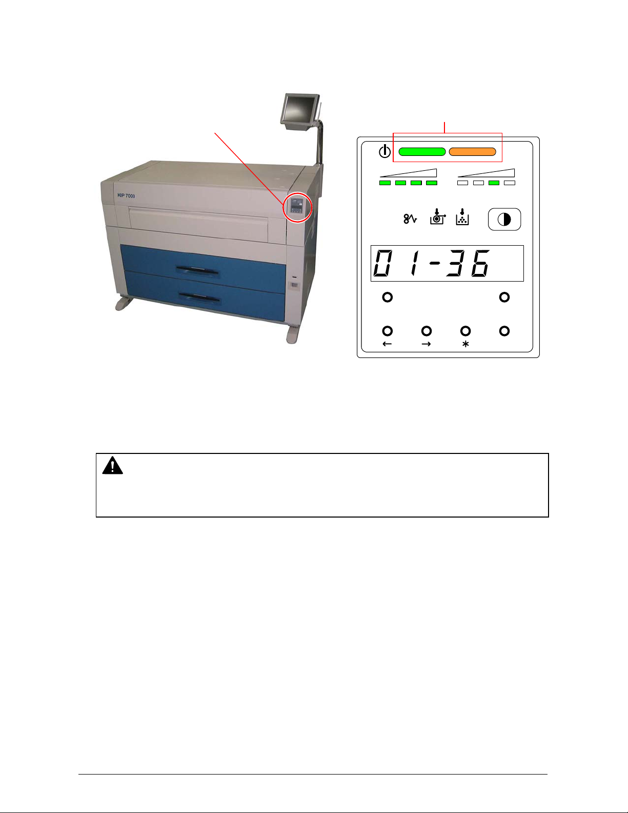
3) There is a Sub Display Panel on the right-front of the printer.
The Orange lamp of the Status Indicator lights when the printer is warming up.
Sub Display Panel
(Left : Green / Right : Orange)
Status Indicator
TONER REMAIN IMAGE DENSI TY
job
MENU TEST
4) When the Fuser has heated up, the Green lamp of the Status Indicator lights and
the printer is ready. (Orange lamp is OFF at that time.) This may take up to 6 minutes from
room temperature.
NOTE
It is impossible to make any prints when the Orange lamp is lit. Please wait until the Green
lamp lights.
5) Print from your computer or copy from the scanner.
ENTER
1-24
Section 1 Basic Printer Functions
Page 31

2. 2 Turning off the Printer
1) Press “OFF” on the Power Switch to turn off the KIP 7000.
CAUTION
The KIP 7000 and the User Interface (UI) look to be shut down when you turn off KIP 7000,
the IPS inside of KIP 7000 is still operating for approximately 2 minutes after Power Switch
operation.
Do not unplug the KIP 7000 before the IPS shutdown. Doing so may damage data or the
device.
Press this side.
1-25
Section 1 Basic Printer Functions
Page 32

2. 3 Replacing the Roll Media
NOTE
The printer indicates the Roll Empty Error by lighting up the Roll Empty Indicator on the
Operation Panel or displays the Empty media screen on the touchscreen. Install new roll
media using the following directions
Roll Empty Indicator
1) When the Roll Empty Indicator lights, check the emptied Roll Deck Number on the Display.
Example : Roll Deck Number is “01”.
This means the media in the
Roll 1 is empty.
2) Open the Roll Deck (1).
Rewind the remaining paper around its core
as indicated by the arrow.
TONER REMAIN IMAGE DENSITY
job
MENU TEST
ENTER
Roll Deck Number
OR
TONER REMAIN IMAGE DENSI TY
job
MENU TEST
ENTER
1
1-26
Section 1 Basic Printer Functions
Page 33

3) Remove the Roll Spool (2) from
the Roll Deck.
2
4) Pull out the Roll Spool (2) from
the core of the roll while
pressing down Lever (3).
3
2
5) Loosen the Thumb Screw (4), and slide the Stopper (5) according to the width of the new roll of
media. Tighten the Thumb Screw to hold the Stopper at the corresponding size mark.
5
4
NOTE
Align the top of triangle (6) of stopper and the
size mark (7).
7
6
3
6
1-27
Section 1 Basic Printer Functions
Page 34

6) Insert the Roll Spool into the core until the Stopper (5) touches the roll media while pressing
down the Lever (3). Then, release the Lever (3) to “catch” the roll media with the Roll Spool.
3
5
3
4
"
3
6
"
A
0
3
6
"
NOTE
Ensure the roll media is wound in the proper direction.
Good
No good
1-28
Section 1 Basic Printer Functions
Page 35

7) Loading Roll 1 or Roll 3
Roll 1
Roll 2
Roll 3
Roll 4
Front
Rear
7-1) Put the Roll Spool back into
the Roll Deck. (Gear side is
Gear side
on the left and Lever side is
on the right.)
NOTE
When you place the Roll Spool back into the Roll Deck, make sure to fit the collar of the right
side of the Roll Spool into the proper position.
No Good Good
(The collar of the Roll Spool is out of (The collar is set in the proper position.)
the proper position.)
1-29
Section 1 Basic Printer Functions
Page 36

7-2) Rotate the green knob to the direction indicated by the arrow and feed the leading edge of the
media between the Feeding Rollers.
7-3) Close the Roll Deck.
7-4) Press the Initial Cut Key on the User Interface (UI) to cut the leading edge.
Remove the cut leading edge.
Knob
NOTE
When you load the media, rotate the Paper Feeding Roller Knob.
too much because the leading edge may come out from the gap. If you close the Roll
Deck while the leading edge is sticking out of the gap, the roll media will fold and printing
will be unavailable.
Knob
Front
Roll 1
Roll 3
Do not feed the media
Roll 2
Roll 4
Rear
1-30
Section 1 Basic Printer Functions
Page 37

8) In Loading Roll 2 or Roll 4
Roll 1
Roll 2
Roll 3
Roll 4
Front
Rear
NOTE
Use the “Operator Aid Arm” to load the roll paper onto the deeper Deck (Roll 2 and Roll 4)
Follow the above procedure for your safety.
Operator Aid Arm
8-1) Place the Roll Spool onto
the Operator Aid Arm. (Gear
side is on the left and Lever
side is on the right.)
1-31
Section 1 Basic Printer Functions
Page 38

8-2) Slide the right side of the
Operator Aid Arm backward.
Then slide the left side of the
Operator aid Arm backward
to install the Roll Spool in the
Roll Deck. (Do not slide both
sides of the Operator Aid
Arm at the same time.)
NOTE
When you place the Roll Spool back into the Roll Deck, make sure to fit the collar of the right
side of the Roll Spool into the proper position.
In Correct Correct
(The collar of the Roll Spool is out of (The collar is set in the proper position.)
the proper position.)
2
1
1-32
Section 1 Basic Printer Functions
Page 39

8-3) Rotate the green knob as shown by the arrow and feed the leading edge of the media
between the Feeding Rollers
Knob
NOTE
When you load the media, rotate the Paper Feeding Roller Knob.
too much because the leading edge may come out from the gap. If you close the Roll
Deck while the leading edge is sticking out of the gap, the roll media will fold and printing
will be unavailable.
8-4) Close the Roll Deck.
8-5) Press the Initial Cut Key on the User Interface (UI) to cut the leading edge.
Remove the cut leading edge.
Front
Roll 1
Roll 3
Do not feed the media
Roll 2
Roll 4
Knob
Rear
1-33
Section 1 Basic Printer Functions
Page 40

2. 4 Replacing the Toner Cartridge
WARNING
There is combustible powder in the toner cartridge. Do not burn the used toner cartridge.
1) Open the Manual Table.
2) Pull out the Upper Frame Unit to your side
with holding both handles.
NOTE
(1) The printer will indicate the Toner Low Error by lighting the Toner Low Indicator on the
Operation Panel or displaying the Toner Low screen the Touch panel as shown
TONER REMAIN IMAGE DENSITY
job
MENU TEST
ENTER
Replace the Toner Cartridge with the new KIP 7000 cartridge using the following procedure:
(2) If your hands or your clothing are soiled by toner, gently dust off the toner. If you are
unable to dust off the toner, wash the clothing with the cold water. (Do not use hot
because it will cause the toner to be absorbed into the fiber.)
OR
Handle
Manual Table
1-34
Section 1 Basic Printer Functions
Page 41

3) Push the Joint rightward to release the Toner Cartridge.
(The joint is latched.)
Joint
4) Press and hold the Lever to the left, and then rotate the Toner Cartridge (not the Cap of
Cartridge) as shown arrow in order to close the opening.
Approximately 2 rotations will be enough to close the opening, but rotate the Toner Cartridge
until it stops completely.
1
2
5) Keep pressing the Lever to the left, and lift up the Toner Cartridge.
2
1
1-35
Section 1 Basic Printer Functions
Page 42

6) Shake a new Toner Cartridge several times right and left to make the toner smooth.
7) Insert the far left Collar of the Toner Cartridge into the slot firmly with pressing the Lever to
the left.
(Please direct the opening of the Toner Cartridge downward at this time.)
2
1
3
8) Pull the Toner Cartridge rightward a little, and insert the swelling in the slot.
1
2
1-36
Section 1 Basic Printer Functions
Page 43

9) Rotate the Toner Cartridge to the arrow direction at least 90 degrees.
(The new Toner Cartridge is closed firmly so as not to lose the toner during the transportation)
10) Push in the Upper Frame Unit firmly.
NOTE
If your hand or your clothing are soiled by toner, dust the toner.
If it is unable to dust it, wash the clothing with the cold water.
(Do not use the hot water at this time because the toner will soak into fiber.)
NOTE
Even if the Joint is not fit to the Toner Cartridge, when you turn on the power, it is
automatically fit properly.
1-37
Section 1 Basic Printer Functions
Page 44

2. 5 Setting the Cut Sheet Paper
1) Open the Manual Table.
2) There are several size mark on the Manual Table. Place the cut sheet paper at the appropriate
size mark, and then insert it into the Bypass Feeder using the size mark as a guide.
NOTE
When the Cut Sheet Paper is inserted manually, its size and media are not indicated on
the Operation Panel.
Manual Table
Size Mark
1-38
Section 1 Basic Printer Functions
Page 45

2. 6 Dehumidifying the Roll Media
If the roll paper is stored in an extremely humid location, it may cause poor prints.
You will most likely experience “creasing” and “voids”.
NOTE
Re-appearance of image (especially solid black image) may occur if you print with humidified
film.
When film is installed in a high humidity environment (higher than 60%RH), we recommend
that you turn on the Dehumidify Heater.
Normal print Re-appeared image
Turn on the Dehumidify Heater if the room air has too much humidity (65% or higher) to prevent the
above kinds of print defect.
You may be able to fix the above kinds of problem.
Normal Print
Normal Print
Creasing
If the media contains
excess humidity
Voids
If the media contains
excess humidity
1-39
Section 1 Basic Printer Functions
Page 46

NOTE
(1) There are several dehumidifying settings that can be set by a certified service
“Dehumidify Heater Switch” is located on the left-rear side of the machine.
Press “H” to turn on the Dehumidify Heater.
technician. These settings establish the dehumidifier functions. For any setting to
function properly, the printer must be plugged in and the switch noted below must be in
the “ON” position.
Call your certified service technician if you would like to change the setting.
Note: the user can not change the setting.
(2) To achieve the best image quality, we recommend that you remove manufacture
packaging just before installing it into the printer. If media is unpacked long before
installation, poor image quality may occur.
Dehumidify Heater Switch
1-40
Section 1 Basic Printer Functions
Page 47

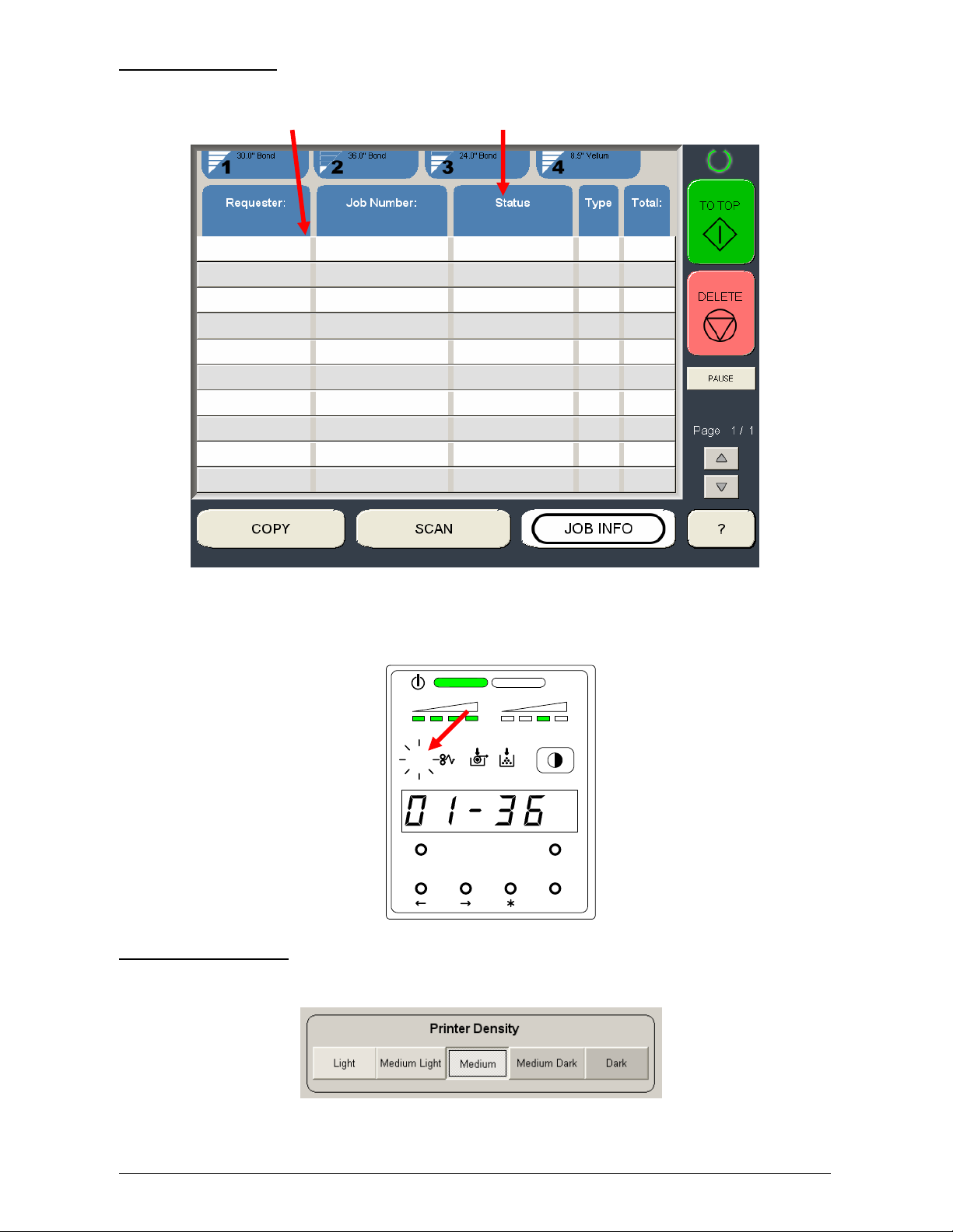
3. 1 Changing the Density Level
Please Set in the Touchscreen - “?”
If you would like to make the image darker or lighter, you will change the density level on the
scanner or controller.
After specifying the density level on the scanner or controller, it is also possible to compensate the
image density on the printer, if needed.
Image Density Indicator
Level 4 (Darkest)
Density Selection Key
There are 4 kinds of levels. (The default setting is Level 3).
Levels are changed by pressing the Density Selection Key.
(The image density gets darker by selecting the bigger level number.)
Level 1 Level 2 Level 3 Level 4
darker darker darker
TONER REMAI N IMAGE DENSITY
Level 1 (Lightest)
job
MENU TEST
ENTER
Section 1 Basic Printer Functions 1-41
Page 48

3. 2 User Mode
To enter the User Mode
Press and hold the [Menu] key for more than 3 seconds.
Then User Mode Number and its contents are shown on the Display.
User Mode Number Contents
You can change the User Mode by pressing [ ] or [ ] key,.
U0. (Reserved) Page 3- 4
U1. Image Enhancement Setting Mode Page 3- 5
U2. Auto Power Off Timer Setting Mode Page 3- 7
U3. Auto Power Off Setting Mode Page 3- 8
U4. Cold Sleep Timer Setting Mode Page 3- 9
U5. Cold Sleep Setting Mode Page 3-10
U6. Warm Sleep Timer Setting Mode Page 3-11
U7. Warm Sleep Setting Mode Page 3-12
U8. (Reserved) Page 3-13
U9. L/L Environment Setting Mode Page 3-14
UA. H/H Environment Setting Mode Page 3-16
Ub. High Coverage Setting Mode Page 3-18
UC. (Reserved) Page 3-19
Ud. (Reserved) Page 3-20
To exit from the User Mode
Press [Menu] key again.
TONER REMAI N I MAGE DENSIT Y
job
MENU TEST
ENTER
Section 1 Basic Printer Functions 1-42
Page 49

3. 2. 1 User Mode 0: (Reserved)
Keep this mode always “oFF”. (Do not change this setting.)
Section 1 Basic Printer Functions 1-43
Page 50

3. 2. 2 User Mode 1: Image Enhancement Setting Mode
Please Set in the Touchscreen - “?”
A weak image can be emphasized by such functions as the Dot Enhancement Level and the
Smoothing Function so that it looks clearer.
Reference
(1) An isolated dot image can be emphasized by the Dot Enhance Level.
(Dot Enhance Level does not affect the compacted dots.)
Isolated dots are emphasized.
(2) A diagonal line tends to look weaker then vertical one or horizontal one.
The Smoothing Function emphasizes the diagonal line so that it becomes as clear as
vertical one or horizontal one.
Diagonal lines are emphasized
Section 1 Basic Printer Functions 1-44
Page 51

1) Select User Mode 1 “U1.” by pressing [ ] or [ ] key.
g
TONER REMAIN IMAGE DENSITY
job
MENU TEST
Applied to the prints
from controller
ENTER
The setting value consists of 2 digits.
The left value is not used.
The right one is applied to the print from controller.
The following list shows the selectable setting value and their contents.
Setting Value Contents
0 Dot Enhancement Level 0 : None
1 Dot Enhancement Level 1 : Weak
With
the Smoothing Function
2 Dot Enhancement Level 2 : Medium
3 Dot Enhancement Level 3 : Strong
4 Dot Enhancement Level 0 : None
5 Dot Enhancement Level 1 : Weak
Without
the Smoothing Function
6 Dot Enhancement Level 2 : Medium
7 Dot Enhancement Level 3 : Strong
2) Press [Enter] key to change the Image Enhancement setting for the print from controller.
TONER REMAIN IMAGE DENSIT Y
job
Image Enhancement setting
for the print from controller
MENU TEST
ENTER
Press this key to change
of settin
for the print
Section 1 Basic Printer Functions 1-45
Page 52

3. 2. 3 User Mode 2: Auto Power Off Timer Setting Mode
This mode allows you to set Auto Power Off Timer.
Reference
The Auto Power Off is the function that the Power Switch turns OFF automatically if the
printer makes no printing (copying) operation for the time decided in the User Mode 2.
(As for turning on the printer, press “ON” of the Power Switch.)
1) Select User Mode 2 “U2.” by pressing [ ] or [ ] key.
The current setting timer is displayed.
2) Press [ * ] (increment) or [Enter] (decrement) key to change the setting value.
Timer is adjustable from 5 to 240 minutes (1 min. step).
NOTE
To make the Auto Power Off work, it is necessary to make this function ON in the Auto
Power Off Setting Mode (User Mode 3). (Refer to page 3-8)
TONER REMAI N IMAGE DENSITY
job
MENU TEST
ENTER
TONER REMAI N I MAGE DENSIT Y
job
MENU TEST
ENTER
Section 1 Basic Printer Functions 1-46
Page 53

3. 2. 4 User Mode 3: Auto Power Off Setting Mode
It is possible to select whether or not the Auto Power Off works.
Reference
The Auto Power Off is the function that the Power Switch turns OFF automatically if the
printer makes no printing (copying) operation for the time decided in the User Mode 2.
(As for turning on the printer, press “ON” of the Power Switch.)
1) Select User Mode 3 “U3.” by pressing [ ] or [ ] key.
U 3. o n : Auto Power Off function works.
U 3. o F F : Auto Power Off function does not work.
2) Select either “on” or “oFF” according to the necessity by pressing [ENTER] key.
TONER R EMAIN I MAGE DENSI TY
job
MENU TEST
ENTER
TONER REMAI N I MAGE DENSIT Y
job
MENU TEST
ENTER
Section 1 Basic Printer Functions 1-47
Page 54

3. 2. 5 User Mode 4: Cold Sleep Timer Setting Mode
Please Set in the Touchscreen - “?”
Do not change this setting.
It is possible to change the timer for the Cold Sleep function on the User Interface (UI).
Reference
1. The purpose of Cold Sleep Mode is to reduce the power consumption by shutting off to
supply the power to the heater unit.
It can save more power than Warm Sleep Mode.
The temperature of the heater unit is about 150 degrees Centigrade when the KIP 7000
is ready. But if no print job or copy job is sent for a long time, it is best for saving the
power to stop supplying the power to the heater unit completely.
The Cold Sleep Mode will be cancelled automatically if only you send a print job or a copy
job from the outer device.
However, please understand it takes a little long time to recover from the Cold Sleep Mode
because it is necessary to raise the temperature again up to about 150 degrees
Centigrade.
(Print does not start until the KIP 7000 gets ready.)
2. When both the Cold Sleep Function and the Warm Sleep Function are effective, their
functions work as follows; (Both timers start simultaneously.)
As for the Warm Sleep Function, refer to page 3-11 to 3-12.
<Example 1>
In case that the Warm Sleep Timer is 15 minutes and the Cold Sleep Timer is
30 minutes, the printer will go into the warm sleep mode in 15 minutes after printing.
And it will also go into the Cold Sleep Mode in 15 minutes after the printer goes into
the Warm Sleep Mode.
<Example 2>
In case that the Warm Sleep Timer is 30 minutes and the Cold Sleep Timer is
15 minutes, the printer will go into the Cold Sleep Mode in 15 minutes after printing.
In this case, the Warm Sleep Function does not work.
Section 1 Basic Printer Functions 1-48
Page 55

3. 2. 6 User Mode 5: Cold Sleep Setting Mode
Please Set in the Touchscreen - “?”
Keep this mode always “oFF”. (Do not change this setting.)
It is possible to select whether the Cold Sleep function works or not on the User Interface (UI).
Reference
The purpose of Cold Sleep Mode is to reduce the power consumption by shutting off to
supply the power to the heater unit.
It can save more power than Warm Sleep Mode.
The temperature of the heater unit is about 150 degrees Centigrade when the KIP 7000
is ready. But if no print job or copy job is sent for a long time, it is best for saving the power to
stop supplying the power to the heater unit completely.
The Cold Sleep Mode will be cancelled automatically if only you send a print job or a copy
job from the outer device.
However, please understand it takes a little long time to recover from the Cold Sleep Mode
because it is necessary to raise the temperature again up to about 150 degrees Centigrade.
(Print does not start until the KIP 7000 gets ready.)
Section 1 Basic Printer Functions 1-49
Page 56

3. 2. 7 User Mode 6: Warm Sleep Timer Setting Mode
Please Set in the Touchscreen - “?”
Do not change this setting.
It is possible to change the timer for the Warm Sleep function on the User Interface (UI).
Reference
1. The purpose of Warm Sleep Mode is to reduce the power consumption by falling down
the temperature of heater some degrees.
The temperature of the heater unit is about 150 degrees Centigrade when the KIP 7000
is ready. But if no print job or copy job is sent for a long time, it is better for saving
the power to fall down the temperature of heater.
(Temperature is kept about 120 degrees Centigrade.)
The Warm Sleep Mode will be cancelled automatically if only you send a print job or
a copy job from the outer device.
However, please understand it takes some minutes to recover from the Warm Sleep Mode
because it is necessary to raise the temperature again up to about 150 degrees
Centigrade.
(Print does not start until the KIP 7000 gets ready.)
2. When both the Cold Sleep Function and the Warm Sleep Function are effective, their
functions work as follows; (Both timers start simultaneously.)
As for the Cold Sleep Function, refer to page 3-9 to 3-10.
<Example 1>
In case that the Warm Sleep Timer is 15 minutes and the Cold Sleep Timer is 30 minutes,
the printer will go into the warm sleep mode in 15 minutes after printing.
And it will also go into the Cold Sleep Mode in 15 minutes after the printer goes into
the Warm Sleep Mode.
<Example 2>
In case that the Warm Sleep Timer is 30 minutes and the Cold Sleep Timer is 15 minutes,
the printer will go into the Cold Sleep Mode in 15 minutes after printing.
In this case, the Warm Sleep Function does not work.
Section 1 Basic Printer Functions 1-50
Page 57

3. 2. 8 User Mode 7: Warm Sleep Setting Mode
Please Set in the Touchscreen - “?”
Keep this mode always “oFF”. (Do not change this setting.)
It is possible to select whether the Warm Sleep function works or not on the User Interface (UI).
Reference
The purpose of Warm Sleep Mode is to reduce the power consumption by falling down the
temperature of heater some degrees.
The temperature of the heater unit is about 150 degrees Centigrade when the KIP 7000
is ready. But if no print job or copy job is sent for a long time, it is better for saving the power
to fall down the temperature of heater. (Temperature is kept about 120 degrees Centigrade.)
The Warm Sleep Mode will be cancelled automatically if only you send a print job or a copy
job from the outer device.
However, please understand it takes some minutes to recover from the Warm Sleep Mode
because it is necessary to raise the temperature again up to about 150 degrees Centigrade.
(Print does not start until the KIP 7000 gets ready.)
Section 1 Basic Printer Functions 1-51
Page 58

3. 2. 9 User Mode 8: (Reserved)
Keep this mode always “oFF”. (Do not change this setting.)
Section 1 Basic Printer Functions 1-52
Page 59

3. 2.10 User Mode 9: L/L Environment Setting Mode
It is possible to select whether or not the L/L Environment Setting Mode should work.
Reference
“Crease of paper” or “Defective fusing” may occur when a large paper (wider than 30”) is
used in the low temperature and low humidity environment (It is called L/L Environment).
This is caused by the fall of temperature of the Heater Unit (hot part inside of the Exit Cover).
If the L/L Environment Setting Mode works, the interval of prints becomes longer than usual
to recover the temperature. (Print productivity is reduced to about 3 sheets / minute although
it is about 7 sheets / minute usually.)
The L/L Environment Mode works not always but only in some specific case, for example
when the remaining volume of roll is very small or when a tracing paper is used.
1) Select User Mode 9 “U9.” by pressing [ ] or [ ] key.
U 9. o n : Low Temperature / Low Humidity Environment Setting works.
U 9. o F F : Low Temperature / Low Humidity Environment Setting does not work.
(Normal operation)
TONER R EMAIN I MAGE DENSI TY
job
MENU TEST
ENTER
Section 1 Basic Printer Functions 1-53
Page 60

2) Select either “on” or “oFF” according to the necessity by pressing [ENTER] key.
TONER REMAI N I MAGE DENSIT Y
job
MENU TEST
ENTER
Section 1 Basic Printer Functions 1-54
Page 61

3. 2.11 User Mode A: H/H Environment Setting Mode
It is possible to select whether or not the H/H Environment Setting Mode should work.
Reference
“Crease of paper” or “Foggy background” may occur when a large paper (wider than 30”) is
installed to the Roll 2 or Roll 4 in the high temperature and high humidity
environment (It is called H/H Environment).
The reason for these problems is that the leading part of paper gets humidified as very long
range of paper is exposed to the humid air because of its waiting position.
If the H/H Environment Setting Mode works, the leading edge is waited at the nearer position
to the roll so that the leading part should not get humidified.
You can avoid the above kinds of problem as a result.
Please note that it takes about 1.5 seconds longer time than usual until the printer completes
the 1st sheet of prints.
<Normal Operation> <H/H Environment Setting works>
Front Rear Front Rear
NOTE
In case this mode is selected under the normal environment, foggy image might be happened.
Waiting position Waiting position
Roll 1 Roll 2
Roll 3 Roll 4
Roll 1 Roll 2
Roll 3 Roll 4
Section 1 Basic Printer Functions 1-55
Page 62

1) Select User Mode A “UA.” by pressing [ ] or [ ] key.
TONER R EMAIN I MAGE DENSI TY
job
MENU TEST
ENTER
U A. o n : H/H Environment Setting works.
U A. o F F : H/H Environment Setting does not work. (Normal operation)
2) Select either “on” or “oFF” according to the necessity by pressing [ENTER] key.
TONER REMAI N I MAGE DENSIT Y
job
MENU TEST
ENTER
Section 1 Basic Printer Functions 1-56
Page 63

3. 2.12 User Mode b: High Coverage Setting Mode
It is possible to select whether or not the High Coverage Setting Mode should work.
High Coverage Setting Mode will be effective if the image density looks lighter when you print
some image pattern which consists of many data.
Please make it work in such case.
1) Select User Mode b “Ub.” by pressing [ ] or [ ] key.
U b. o n : High Coverage Setting Mode works.
U b. o F F : High Coverage Setting Mode does not work. (Normal operation)
2) Select either “on” or “oFF” according to the necessity by pressing [ENTER] key.
TONER R EMAIN I MAGE DENSI TY
job
MENU TEST
ENTER
TONER REMAI N I MAGE DENSIT Y
job
MENU TEST
ENTER
Section 1 Basic Printer Functions 1-57
Page 64

3. 2.13 User Mode C: (Reserved)
Keep this mode always “oFF”. (Do not change this setting.)
3. 3.14 User Mode d: (Reserved)
Keep this mode always “oFF”. (Do not change this setting.)
Section 1 Basic Printer Functions 1-58
Page 65

4. 0 Error Correction
4. 1 Mis-feed Errors
If a paper mis-feed occurs, the Paper Mis-feed Indicator on the Sub Display and a screen on the
Touchscreen inform you of the error and the location. The Sub Display indicates a mis-feed code
(J-XX) to let you know where the paper is mis-fed. The Touchscreen will describe the location and
supply a guide on the screen.
Paper Mis-feed Error
TONER REMAIN I MAGE DENSI TY
job
MENU TEST
ENTER
Paper Mis-feed Code
J-01 (Paper Mis-feed in the Roll 1)
Refer to the following diagram for the location of the paper mis-feed indicated by the code on the
Sub Display (Greater details on each code are on the following pages.)
Section 1 Basic Printer Functions
OR
1-59
Page 66

Please check where the Paper Mis-feed has occurred referring to the following diagram.
(Greater detail on each code are on the following pages.)
J-11
J-12
J-13、J-14
J-21、J-22
J-05
J-10
J-01
Outer Device
(Auto Stacker,
Folder, etc.)
Roll 1 Roll 2
J-02
J-03
J-04
Front
Roll 3 Roll 4
Rear
NOTE
(1) Remove the mis-fed paper being careful not to cut your hand on the paper edge.
(2) Take off necklaces, bracelets, rings and wrist watch before removing the mis-fed paper.
Failure to do so may result in burns or electrical shock if the metal accessories touch the
interior of the printer.
(3) The toner image is not adhered correctly if the paper did not reach the Fuser Section.
Take care to ensure the toner does not rub onto your clothing when you remove the misfeed. If toner gets onto your clothing gently dust it off. If it does not dust off, was the article in
cold water. (Do not use hot water as it causes the fiber to absorb the toner.)
(4) The toner image is not adhered correctly if the paper did not reach the Fuser Section.
Take care to ensure that toner does not get into your eye, and take care not to inhale the
toner. (Please flush the contaminated area with water if toner gets into your eye or mouth.)
Section 1 Basic Printer Functions
1-60
Page 67

4. 1. 1 Mis-feed in the Roll Deck Section
(J-01, J-02, J-03, J-04)
When the Paper Mis-feed occurs in the Roll Deck, the Sub Display Panel indicates any of “J-01”,
“J-02”, “J-03” and “J-04”.
J-01 : In the Roll 1
J-02 : In the Roll 2
J-03 : In the Roll 3
J-04 : In the Roll 4
J-01
J-02
Roll 1
Roll 2
J-03
J-04
Front Rear
Roll 3
Roll 4
Clear the Paper Mis-feed using the following procedure:
1) Open the Roll Deck in issue. And then rewind the roll onto the media core.
TONER REMAI N I MAGE DENSITY
job
MENU TEST
ENTER
Section 1 Basic Printer Functions
1-61
Page 68

2) If the leading edge of the media is torn or folded, cut it off.
3) Set the roll media correctly.
NOTE
When you put back the Roll Spool into the Roll Deck, make sure to fit the collar of the right
side of the Roll Spool into the proper position.
No Good Good
(The collar of the Roll Spool is out of (The collar is set in the proper position.)
the proper position.)
4) Close the Roll Deck.
Section 1 Basic Printer Functions
1-62
Page 69

4. 1. 2 Mis-feed in the Manual Feeder Section (J-05)
When the paper mis-feed occurs in the Manual Feeder, the Sub Display Panel indicates “J-05”.
J-05
Roll 1
Roll 2
Roll 3
Roll 4
Front Rear
Clear the Paper Mis-feed using the following procedure:
1) Pull out the mis-fed paper from the Manual Feeder, and if the leading edge of the paper is torn
or folded, replace with the new one.
TONER REMAI N IMAGE DENSITY
job
MENU TEST
ENTER
Section 1 Basic Printer Functions
1-63
Page 70

4. 1. 3 Mis-feed in the Paper Feed Section
(J-10, J-11, J-12)
When the Paper Mis-feed occurs in the Paper Feed Section, Sub Display Panel indicates any of
“J-10”, “J-11” and “J-12” according to the position of mis-feed.
J-10 : Front area
J-11 : Middle area
J-12 : Rear area
J-10 J-11 J-12
Roll 1
Roll 2
Roll 3
Roll 4
Front Rear
TONER RE MAIN I MAGE DENSIT Y
job
MENU TEST
ENTER
TONER REMAI N I MAGE DENSI TY
job
MENU TEST
ENTER
TONER REMAI N I MAGE DENSI TY
job
MENU TEST
ENTER
Section 1 Basic Printer Functions
1-64
Page 71

Clear the Paper Mis-feed using the following procedure:
1) Press the Initial Cut Key on the User Interface (UI).
NOTE
The roll paper is cut hereby even if it has not been cut at the time of mis-feed.
(1) Once you make the Cutter work by pressing the Initial Cut Key on the User Interface (UI),
it will not work again even if you press the Cut key more times.
(2) In case the Cutter has worked already to cut the roll paper at the time of mis-feed,
it will not work even if you press the Initial Cut key on the User Interface (UI).
2) Open the Manual Table.
3) Pull out the Upper Frame Unit to your side
holding both handles.
Manual Table
Handles
4) Pull up both knobs, and then push
the Top Cover to rear side.
Top Cover
Knob
5) Remove the mis-fed paper.
6) Close the Top Cover and the Upper Frame Unit.
7) Close the Manual Table.
Section 1 Basic Printer Functions
1-65
Page 72

4. 1. 4 Mis-feed in the Fuser Section (J-13, J-14)
When the Paper Mis-feed occurs in the Fuser Section, the Sub Display Panel indicates either of
“J-13” and “J-14”.
J-13, J-14
Roll 1
Roll 2
Roll 3
Roll 4
Front
Rear
TONER REMAIN IMAGE DENSITY
job
MENU TEST
ENTER
TONER REMAIN IMAGE DENSITY
job
MENU TEST
ENTER
Section 1 Basic Printer Functions
1-66
Page 73

Clear the Paper Mis-feed using the following procedure:
1) Press the Initial Cut Key on the User Interface (UI).
NOTE
The roll paper is cut hereby even if it has not been cut at the time of mis-feed.
(1) Once you make the Cutter work by pressing the Initial Cut Key on the User Interface (UI),
it will not work again even if you press the Cut key more times.
(2) In case the Cutter has worked already to cut the roll paper at the time of mis-feed,
it will not work even if you press the Initial Cut key on the User Interface (UI).
2) Open the Exit Cover.
Exit Cover
WARNING
There are extremely hot parts inside the Heater Unit.
Do not touch any parts in the Heater Unit, or you will be burnt.
Also the mis-fed media can be very hot.
Be careful not to get burnt when you remove it.
3) If it is possible to access the mis-fed paper, pull it out backward gently.
Be careful not to tear the mis-fed paper.
If it is not possible to access it, go to the next step.
Section 1 Basic Printer Functions
1-67
Page 74

4) Open the Manual Table.
5) Pull out the Upper Frame Unit to your side
holding both handles.
6) Pull up both knobs, and then push
the Top Cover to rear side.
7) Remove the mis-fed paper.
8) Close the Top Cover and the Upper Frame Unit.
9) Close the Manual Table.
Knob
Manual Table
Handles
Top Cover
Section 1 Basic Printer Functions
1-68
Page 75

4. 1. 5 Mis-feed in Stacker (J-21, J-22)
When the Paper Mis-feed occurs in the stacker, the Sub Display Panel indicates either of
“J-21” or “J-22”.
TONER REMAI N IMAGE DENSI TY
job
MENU TEST
ENTER
Clear the mis-feed using the following procedure:
1) As for the way to clear the mis-feed, refer to the User’s Manual for the Stacker.
TONER RE MAIN IMAGE DENSI TY
job
MENU TEST
ENTER
Section 1 Basic Printer Functions
1-69
Page 76

4. 2 Open Cover Errors
The Sub Display Panel will indicate the error code (U-XX) if there are any open decks or open
covers.
Close each deck (or cover) as it is impossible to print, if this error exists.
4. 2. 1 Roll Deck Open (U-01, U-02)
The corresponding Roll Deck is opened when the Sub Display Panel indicates “U-01” or “U-02”.
U-01 : Upper Roll Deck is opened.
U-02 : Lower Roll Deck is opened.
(Example : Upper Roll Deck is opened.)
Firmly close the Roll Deck by pressing a little strongly toward the machine.
TONER REMAI N IMAGE DENSI TY
job
MENU TEST
ENTER
Section 1 Basic Printer Functions 1-70
Page 77

NOTE
This error code will be indicated if the Roll Deck is not locked correctly, although it may look
closed.
Open and close the Roll Deck again, pushing until locked. Ensure both sides of the roll deck
are in their correct position.
The Roll Deck is firmly locked.
The Roll Deck is unlocked.
Close the deck firmly.
OK
NG
Section 1 Basic Printer Functions 1-71
Page 78

4. 2. 2 Upper Frame Unit / Top Cover Open (U-05)
When either the Upper Frame Unit or the Top Cover is opened the Sub Display Panel indicates
“U-05”.
Check if the Upper Frame Unit and the Top Cover are closed firmly.
Top Cover
Upper Frame Unit
TONER REMAIN IMAGE DENSITY
job
MENU TEST
ENTER
OK
NG
Section 1 Basic Printer Functions 1-72
Page 79

4. 2. 3 Exit Cover Open (U-06)
When the Exit Cover is opened, the Sub Display Panel indicates “U-06”.
Close the Exit Cover.
TONER REMAIN IMAGE DENSITY
job
MENU TEST
ENTER
Exit Cover
Section 1 Basic Printer Functions 1-73
Page 80

4. 3 Other Errors
4. 3. 1 Toner Low
The machine indicates a “Toner Low” by lighting the Toner Low Indicator on the Sub Display Panel.
Toner Cartridge replacement is required.
Refer to [2.4 Replacing the Toner Cartridge] on page 2-14.
Toner Low Indicator
TONER REMAIN I MAGE DENSITY
job
MENU TEST
ENTER
Section 1 Basic Printer Functions 1-74
Page 81

4. 3. 2 Roll Empty
The machine indicates a “Roll Empty” by lighting the Roll Empty Indicator on the Sub Display
Panel if the roll media currently in use is consumed during printing.
Installation of a new roll is required.
Refer to [2.3 Replacing the Roll Media] on page 2-5.
Roll Empty Indicator
TONER R EMAIN I MAGE DENSIT Y
job
MENU TEST
ENTER
Section 1 Basic Printer Functions 1-75
Page 82

4. 3. 3 No Manual Paper (P.E.)
The machine indicates “P.E.-XX” on the Sub Display Panel when the cut sheet paper is not set on
the Manual Feeder. “XX” means the required paper size.
Set the indicated size of paper.
Refer to [2.5 Setting the Cut Sheet Paper] on page 2-18.
When the Manual Paper is inserted, indication is changed from [P.E.] to [b.p.] automatically.
TONER REMAIN IMAGE DENSITY
job
Required paper size
MENU TEST
ENTER
TONER REMAIN IMAGE DENSITY
job
MENU TEST
ENTER
Section 1 Basic Printer Functions 1-76
Page 83

4. 4 Call Service Errors
You will note one of the following Error Codes on the Operation panel if the machine has the fatal
error.
It is impossible for the user to cure these errors to resolve these issues.
PLEASE CALL YOUR TRAINED SERVICE PERSONNEL TO RESOLVE THESE ERRORS.
Error Code Name of the error
E - 01 Fuser Temperature Rising Error
E - 02 Fuser Over Temperature Error
E - 03 Main Motor Error
E - 04 Developer Error
E - 06 Counter Error
E - 07 Cutter Error
E - 14 Fuser Motor Error
E - 16 Wire Cleaning Error
E - 21 Fuser Thermostat Error
E - 23 LED Head Cleaning Error
E - 40 Outer Device Error
E - 41 Key Card Error
E - 51 High Voltage Power Error
If any of the above errors is displayed:
1) Turn off the printer, wait approximately 30 seconds, and then turn on the printer again.
2) If the same error code is displayed, turn off the printer, and then unplug the printer from the wall
outlet.
Call your service personnel.
Section 1 Basic Printer Functions 1-77
Page 84

Section 2
Job Info Screen
1. 0 Job Info Screen 2- 2
1.1 Main Screen – Summary 2- 2
2. 0 Operation Details 2- 3
2.1 Job List - Main Screen 2- 3
2.2 User Name 2- 4
2.3 Job – Number 2- 4
2.4 Status 2- 4
2.5 Type 2- 5
2.6 Total 2- 5
2.7 Delete 2- 5
2.8 Change of Media in a Print Job 2- 6
2.9 To Top 2- 6
2.10 Pause 2- 7
2.11 Page Scroll 2- 7
2.12 Media Information 2- 8
2.13 Change Media Information 2- 8
Section 2 Job Info Screen 2-1
Page 85

1. 0 Job Info Screen
1.1 Main Screen
2
No. Name Function
1 Mode Selects the “Mode” of the system. (Job Mode for this
2 User Name – Job # Display the User and any user info for the job ID. A job
3 Media Information Displays and allows change of the Width and Type.
4 Status Shows the current status of a job and media selection.
5 Type Displays a copy or network print job
6 Total Displays the total number of prints and current number
7 To Top After a job is selected (see #2) the position in the queue
8 Pause Pauses printer to allow media change, etc
3
screen shown)
can be selected for other functions noted below.
Shows the amount remaining per roll deck. (two or four
rolls depended on system)
printed.
can be changed to the next job printed.
4
1
5
6
7
8
9
10
9 Delete After a job is selected (see #2) it can be removed from
printing.
10 Up/Down Scrolls through pages in the queue if so available.
Section 2 Job Info Screen 2-2
Page 86

2. 0 Operation Details
The Job Info screen is used to view or manage the current copy or prints jobs on the KIP
7000.
2.1 Job List - Main Screen
All jobs that are currently printing or are waiting to print are displayed in this area.
You may view a jobs details, (or for other functions described further in this manual) by
selecting the job from the list
Section 2 Job Info Screen 2-3
Page 87

2.2 User Name
Displays the “Name” or the “owner” of the job
This information is obtained from fields within:
a) KIP Request
b) KIP Windows Driver
c) KIP AutoCAD Driver
d) Or from the Accounting Fields on the copier when accounting is
enabled
Please see respective User Guides for detailed information
An example screen from Request:
2.3 Job Number
Displays the “Job Number” or details regarding the job
This information is obtained from fields within:
e) KIP Request
f) KIP Windows Driver
g) KIP AutoCAD Driver
h) Or from the Accounting Fields on the copier / scanner when
accounting is enabled
An example from Copy / Scan Accounting:
Section 2 Job Info Screen 2-4
Page 88

2.4 Status
Displays the current “Status” of a job.
Displays one of the following:
a) Processing – job is currently printing
b) On Hold – puts the job in the queue but will not print until
a valid media type is applied
c) Vellum – Media required - Vellum
d) Film – Media required - Film
e) Bond – Media required - bond
2.5 Type
Displays the source of the job, jobs can be sent from the network or come from the copier
functions.
For network jobs, the following symbol is displayed:
For copy job the following symbol is displayed:
2.6 Total
Displays the number of prints, this includes:
a) the quantity in each job
b) the amount remaining , when a job is printing.
Section 2 Job Info Screen 2-5
Page 89

2.7 Delete
To remove a job from the Job list:
a) Select the job to remove
Another Screen will appear.
b) Press the Delete button
c) The job will be removed from the list.
Section 2 Job Info Screen 2-6
Page 90

2.8 Change Media Type in Print Job
To change the media type in a job that may be in the job list:
a) Select the job
b) Job Information screen will appear.
c) Press the Bond, Vellum
or Film button to set the
new media type for this
job.
Section 2 Job Info Screen 2-7
Page 91

2.9 To Top
If a job in the list is required urgently and there are other jobs in the list prior to it, the job
can be moved to the top of the queue.
a) Select the job from the list
b) Press the “To Top” button
c) The list will be updated with urgent job to be printed next.
2.10 Pause
To pause all print jobs (to replace paper or perform another task that
may require the printer to pause) press the pause button.
Section 2 Job Info Screen 2-8
Page 92

2.11 Page Scroll
Arrows may appear in the lower right corner of the screen to scroll through
the pages of jobs. Please note that the total number of pages will be
displayed as well as the current page.
2.12 Media Information
At the top of the Job List Screen is the region that displays the current media loaded in KIP
7000. Please note that only rolls the printer has will be displayed.
Amount Remaining Type
Roll Deck Number Width
a) Roll Deck Number
b) Amount Remaining: shows the quantity of media in ¼ steps.
Example: Roll 1 is full
Roll 2 is ¼ full
Roll 3 is ¾ full
Roll 4 is also full
If no media installed then all bars would be empty
c) Type: Shows the media type ( set by User )
Example: Roll 1 is Bond
Roll 4 is Vellum
d) Width: Shows the set width ( set by User )
Example: Roll 1 is 30”
Roll 2 is 36”
Roll 3 is 24”
Roll 4 is 11”
Section 2 Job Info Screen 2-9
Page 93

2.13 Change Media Information
At the top of the Job List Screen is the region that displays the current media loaded in KIP
7000. Please note that only rolls the printer has will be displayed.
a) Touch any area of this region to the set media type and width in all roll decks
b) Select the correct media width and type for each deck as required ( two roll model
screen shown below )
c) Select OK to set
d) The new settings will be noted on the top of the Job Info Screen
Section 2 Job Info Screen 2-10
Page 94

2.14 Job History
KIP Job History can be used to call up and print jobs that were previously printed. By
selecting a job from the Job History list, the job can be changed and resubmitted for
printing.
1. To use the KIP Job History select the Job Info Button and click on the Current
Job button
2. The Job History Information will now be displayed on the screen and select the
job to be edited.
3. Select the Edit Button to access the available options for the current selected job.
Section 2 Job Info Screen 2-11
Page 95

4. Users have the option to change Accounting information, Media type, Number of
Originals and number of sets. Or to delete the job from History.
5. When all changes (if any) are complete select the Submit button to send the job
to the printer.
Section 2 Job Info Screen 2-12
Page 96

Section 3
“?” Screen
1.0 ? – Configuration Screen ................................................................................... 3- 2
1.1 Overview ................................................................................................... 3- 2
1.2 “?” Screen – General................................................................................. 3- 3
2.0 Main Screen - Details.......................................................................................... 3- 4
2.1 Information Region....................................................................................3- 4
2.1.1 Meter A..................................................................................... 3- 4
2.1.2 Total Run.................................................................................. 3- 5
2.1.3 Meter B..................................................................................... 3- 5
2.1.4 Scan Count............................................................................... 3- 5
2.1.5 Scan Count- Temp ................................................................... 3- 5
2.1.6 Software version....................................................................... 3- 5
2.1.7 Firmware Version ..................................................................... 3- 5
2.1.8 IPS Number.............................................................................. 3- 5
2.1.9 Machine Serial Number............................................................ 3- 5
2.2 Supplier / Technical Support..................................................................... 3- 6
3.0 User Guides......................................................................................................... 3- 7
4.0 Configuration ...................................................................................................... 3- 8
4.1 Printer Density........................................................................................... 3- 8
4.2 Power Save Settings.................................................................................3- 9
4.3 Default Mode............................................................................................. 3- 9
4.4 Master Lead / Trail Adjustment ................................................................ 3- 10
4.5 Test pattern.............................................................................................. 3- 10
4.6 Options..................................................................................................... 3- 11
4.7 Network.................................................................................................... 3- 11
4.8 Reset Timer.............................................................................................. 3- 11
4.9 Language ................................................................................................. 3- 12
4.10 Inch or Metric Units ................................................................................. 3- 12
4.11 Copy and Scan Menu Defaults ...............................................................3- 13
4.12 Fold ......................................................................................................... 3- 14
4.13 Cut Sheet ................................................................................................ 3- 14
4.14 Interrupt................................................................................................... 3- 14
4.15 Reset Job Info......................................................................................... 3- 15
4.16 Reboot IPS.............................................................................................. 3- 15
4.17 Current Time ........................................................................................... 3- 15
5.0
Color Configuration........................................................................................... 3- 16
6.0
Other Buttons.....................................................................................................3- 19
3-1 Section 3 ?” Screen
Page 97

1.0 Help – Configuration Screen
1.1 Overview
The KIP 7000 has the ability to display information about the system and allow detailed
configuration or setting of the KIP 7000 for Copy and Scan modes.
It also has visual user guides which can assist the user in perform the functions of the KIP
7000.
To Enter the “Help – Configuration” screen press on the “?” on the bottom right of the KIP
7000 user interface.
Some of the configurable settings include:
a) Language
b) Sleep Timers
c) Energy Star - Mode
d) Reset Timer for Memory and Default Settings
e) Printer Density
f) Master Lead / Trail Edge
g) Default Mode
h) Units (Metric or Inch)
i) Default Original Size Mode
j) Quality / Scan Speed
k) Number of Rolls
l) Shading
m) Test patterns
n) Enable Options
o) Network IP settings
Some of the above settings will require access by the system administrator, key operator or
a certified service technician.
3-2 Section 3 ?” Screen
Page 98

1.2 “?” Screen – General
3
2
No. Name Function
1 Mode Selects the “Mode” of the system. (Help Mode
2 Information Region Displays meter counts and version number of
3 Support / Supplies Displays the contact information for technical
4 User Guide Enters the Graphical Users Guides.
5 Configuration Enters the settings and configurations modes.
6 Print This Screen Prints the main “?” screen on the KIP 7000
7 Service Password protected area for KIP authorized
8 Color Config Configures the optional color scan and color
4
5
6
7
8
1
shown)
the system.
support and printer supplies.
technician use.
copy features.
3-3 Section 3 ?” Screen
Page 99

2.0 Main Screen - Details
2.1 Information Region
This area of the Screen includes meter counts and software versions
.
2.1.1 Meter A
Displays the total number of units run on the printer. This counter should match the hard
counter on the right mid- front section on the printer. This unit is in square feet in North
America and in Square Meters in all other countries (when printer set to metric mode).
English mode: 1 count = one square foot
Metric Mode: 1 count = one square meter
NOTE
If this counter differs from the hard counter on the printer contact your local
service company!
The units of this counter are taken from the internal processor of the printer and
can be “reset” if care is not taken upon replacement of the DC Controller.
Please see KIP 7000 Service Manual for details on the setting procedures.
In case of discrepancies: The hard counter shall be taken as the correct value!
3-4 Section 3 ?” Screen
Page 100

2.1.2 Total Run
This meter counts the total number of linear meters run on the printer in all countries. One
count = one linear meter
2.1.3 Meter B
This counter can be reset at any time to count the units in a particular job. The date of last
“reset” is also displayed. This counter’s units are the same as Meter A. Press the reset
button to start at “0”
2.1.4 Scan Count
The Scan Count displays the total count of the “imaged” area. If the original was larger than
the saved imaged area only the saved imaged area is recorded. If the incorrect original size
was selected the selected size will be recorded.
Example:
With a 24x36 original
2.1.5 Scan Count- Temp
This counter can be reset at any time to count the units in a particular job if so required.
The date of last “reset” is also displayed. This counter’s units are the same as in Scan
Count. Press the reset button to start at “0”
2.1.6 Software version
Displays the software IPS version for technical support
2.1.7 Firmware Version
Displays the printer firmware version for technical support
2.1.8 IPS Number
Displays the current IPS number, this is required for any optional upgrades to the KIP 7000.
2.1.9 Machine Serial Number
Displays the KIP 7000 hardware serial number, this is also located on the lower rear of the
printer.
NOTE
The units of this counter are taken from the internal processor of the printer and
can be “reset” if care is not taken upon replacement of the DC Controller.
Please see KIP 7000 Service Manual for details on the setting procedures.
In case of discrepancies: The hard counter shall be taken as the correct value!
1) If the original was feed 36” wide with a 36” wide setting on the User Interface
then 6 sq ft recorded.
2) If the 36” wide original was scanned in at a 24” wide manual setting, the size
will be recorded as 24x24 or 2 square feet.
NOTE
If this serial number differs from the “hard coded” number on the lower rear of
the printer contact your local service company! The hard code serial will be
taken as correct in the case of any discrepancies.
3-5 Section 3 ?” Screen
 Loading...