

Konica Minolta DRYPRO SIGMA Installation Manual

KONICA MINOLTA DRYPRO SIGMA Laser Imaging System
Film Types
The DRYPRO SIGMA Laser Imager prints on KONICA MINOLTA Medical Imaging Film.
Intended Use
The DRYPRO SIGMA Laser Imaging System is intended to provide hard copy images
from digital imaging source output signals onto KONICA MINOLTA MEDICAL IMAGING
FILM SD-S. The device is intended for use with a variety of digital modalities,
including, but not limited to, CR (Computed Radiology), DR (Digital Radiology), CT
(Computerized Tomography) and MRI (Magnetic Resonance Imaging). The images
are to be used for medical diagnosis and referral to physicians and their patients.
This device is not intended to be used with Full Field Digital Mammography units or
Computed Radiography units supporting digital mammography.
Getting Started
Your laser imager comes with several publications to help you get started quickly and
safely. Locate the following publications:
• SafetyManual(9G7565):Reviewthismanualrsttounderstandhowtopositionandwork
with the laser imager safely and within regulations.
• Pre-Installation Manual (9G7563): Ensure that your site is ready for the installation.
• Installation Manual (9G7567): Learn how to install the laser imager.
• Operation Manual (9G7564): See this guide for a product overview, use instructions, and
troubleshooting tips.
• Quick Reference Card (9G7566): Keep this card in a convenient place and reference it as
needed.
Pub history:
A: 2011-03-31. First release.
B: Updated the company name.
Pub No. 9G7571_en, Rev. B, 2013-04-01
© KONICA MINOLTA, INC., 2013
KONICA MINOLTA and DRYPRO are trademarks of KONICA
MINOLTA, INC.
KONICA MINOLTA, INC.
1 Sakura-machi, Hino-shi, Tokyo, 191-8511, Japan
Installation Manual
CAUTION:
Requirements to install the laser imager
The laser imager weighs approximately 54 kg (120 lb). Two
people must use safe lifting techniques to move the laser
imager. One person can complete the remaining steps. The
installation must be performed by qualified personnel.
Task Recommended Skill or Knowledge
Unpack the laser imager. Ability to use common hand tools.
Use a personal computer to view the documentation on
the publications disc supplied with the laser imager.
Connect a personal computer to the laser imager and
enter the network information.
Configure the laser imager to print from a modality. Familiarity with DICOM protocol.
Make a backup disk of the configuration. Understand personal computer file name
Basic personal computer skills.
Familiarity with TCP/IP network addressing
conventions.
conventions.
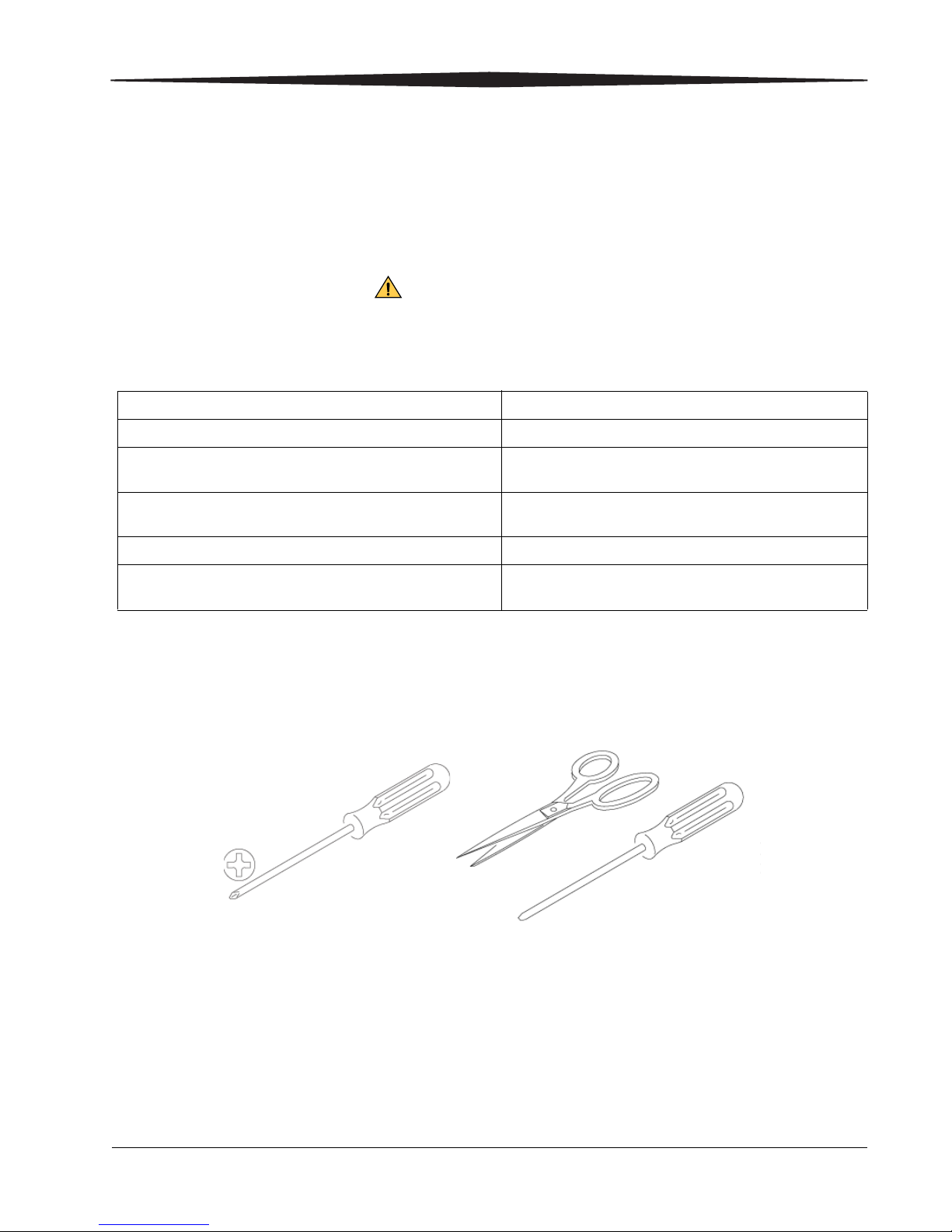
Required tools • Phillips screwdriver
• Scissors
• Straight blade screwdriver
• Crossover cable (not shown)
Required information You will need:
2015-04-17 9G7567_en 1
• IP Address and related network information for the laser imager
• Configuration information for each modality that will print to the laser
imager
This information should have been previously collected and recorded in
the Pre-Installation Manual that was provided to your site.
If you do not have the Pre-Installation Manual, contact your dealer or
qualified service provider.
Unpacking the laser imager
CAUTION:
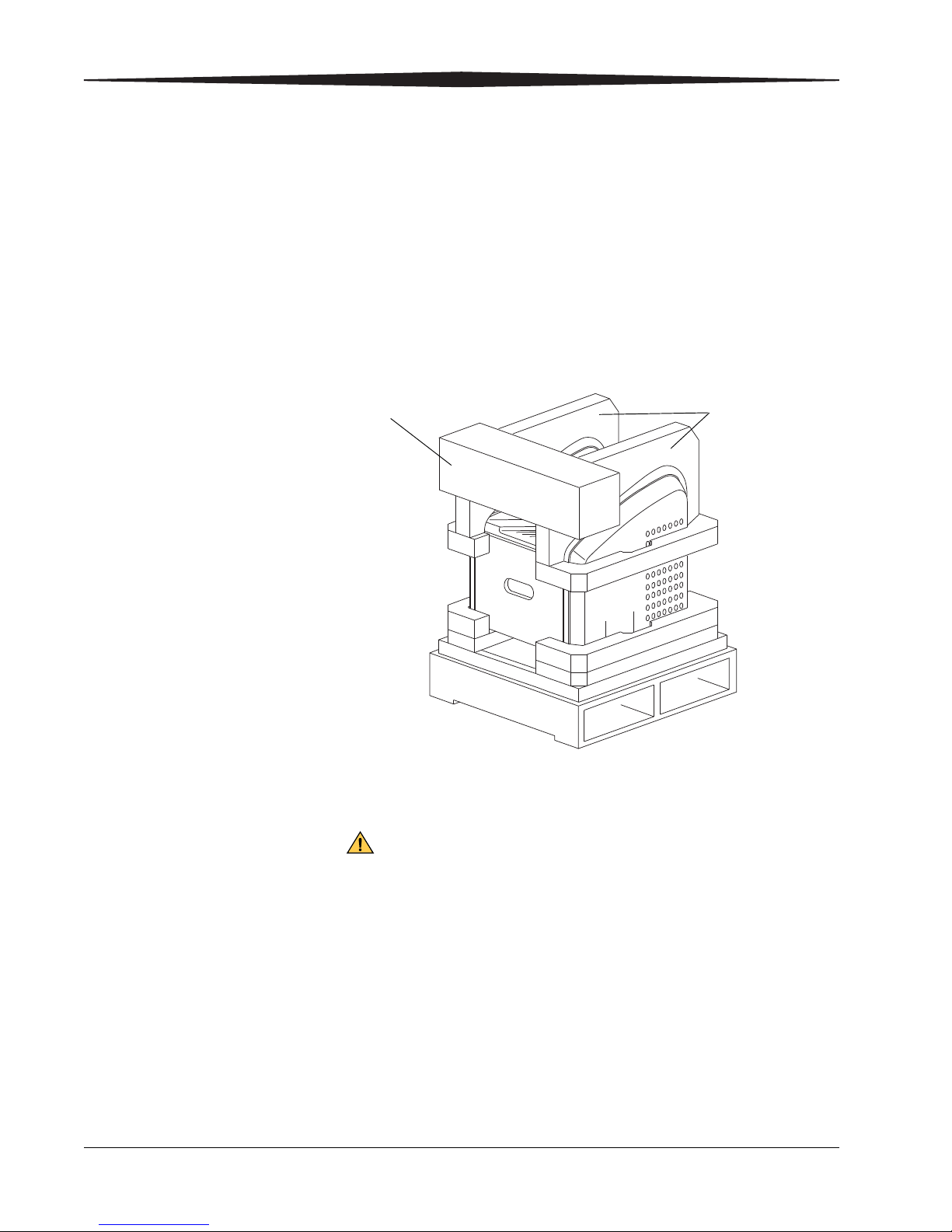
Foam Assemblies
Accessories
Box
Checking the
accessories
Check that the following items are included in the accessories box:
• Power cord
• Network cable
• Deodorant filter
• Publications kit
IMPORTANT: Please read the Safety Manual before you proceed to
install or operate the laser imager.
2 9G7567_en 2015-04-17
1. Remove the two foam assemblies.
2. Open the bag that covers the laser imager.
Use safe lifting techniques and two people to move the laser
imager.
3. Lift the laser imager from the carton and set it on a flat surface.
Position the laser imager temporarily so there is a space of at least
1 m (39 in.) at the back of the laser imager.
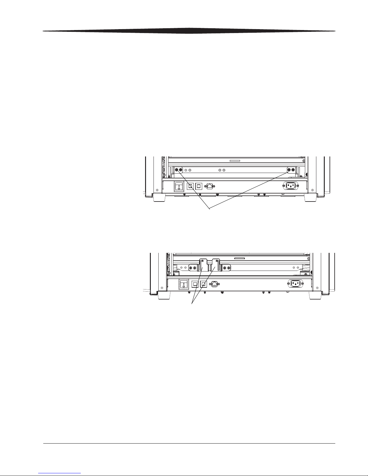
Moving the shipping
Shipping Brackets
Shipping Brackets reattached
brackets and retainer
Shipping brackets are fastened inside the la ser imager to keep the parts
safe during shipment. You must remove them, and then reinstall them in
a different location (as shown) inside the laser imager. This prevents the
shipping brackets from becoming lost. You must also remove the rollback
retainer.
NOTE: If it is necessary to ship the laser imager again, you must return
the shipping brackets to the shipping locations.
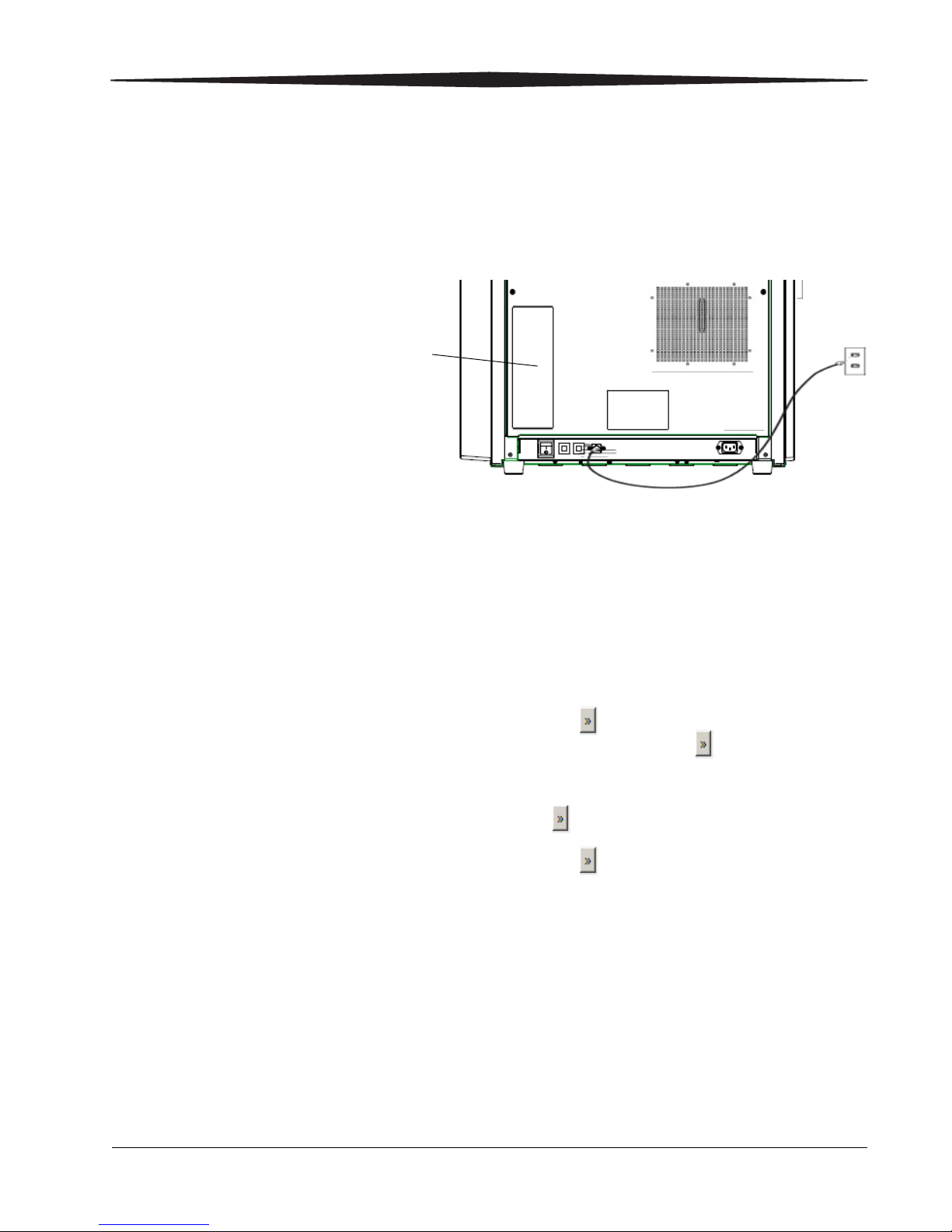
1. To move the back shipping brackets, remove:
a. Back cover
b. 4 screws that fasten the 2 shippin g brackets
Back view of laser imager
2. Rotate the shipping brackets and reattach them in the alternate set
of holes on the rail.
3. Retain the other 2 bracket screws: Install the screws into any of the
empty holes where the bracket was attached earlier.
4. Replace the back cover.
5. At the front of the imager, open the film supply. Reach in and
remove the foam rollback retainer.
2015-04-17 9G7567_en 3
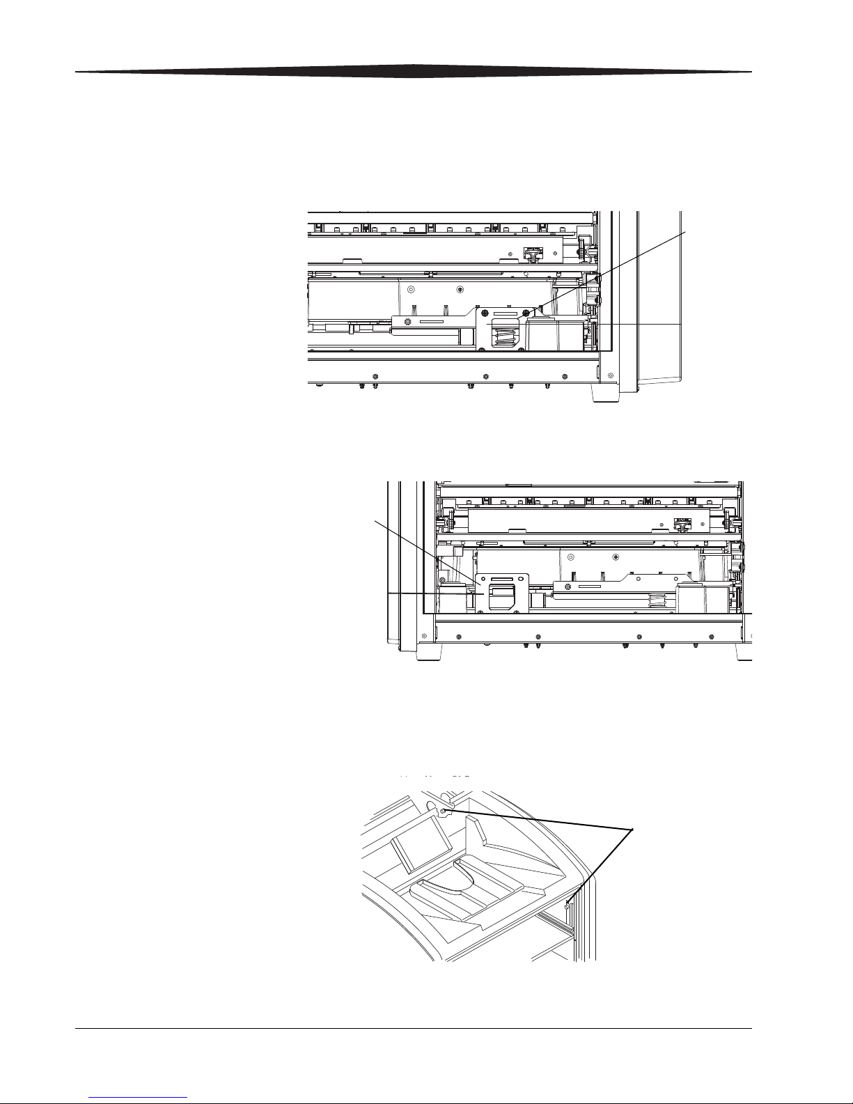
6. To move the front shipping bracket, remove 4 screws that fasten the
FRONT SHIPPING
BRACKET
(FILTER REMOVED
Shipping
Bracket
Front Shipping
Bracket in
Storage
Shipping
Bracket
reattached
H221_6003AC
2 screws
shipping bracket.
Front view of laser imager
7. Use 2 of the screws to reattach the shipping bracket in the alternate
set of holes on the left side of the rail.
4 9G7567_en 2015-04-17
8. Retain the other 2 bracket screws: Install the screws into any of the
empty holes where the bracket was attached earlier.
9. Remove the right cover:
a. Remove the top cover. (Leave the film supply open.)
b. Remove 2 screws that attach to the right cover standoffs.
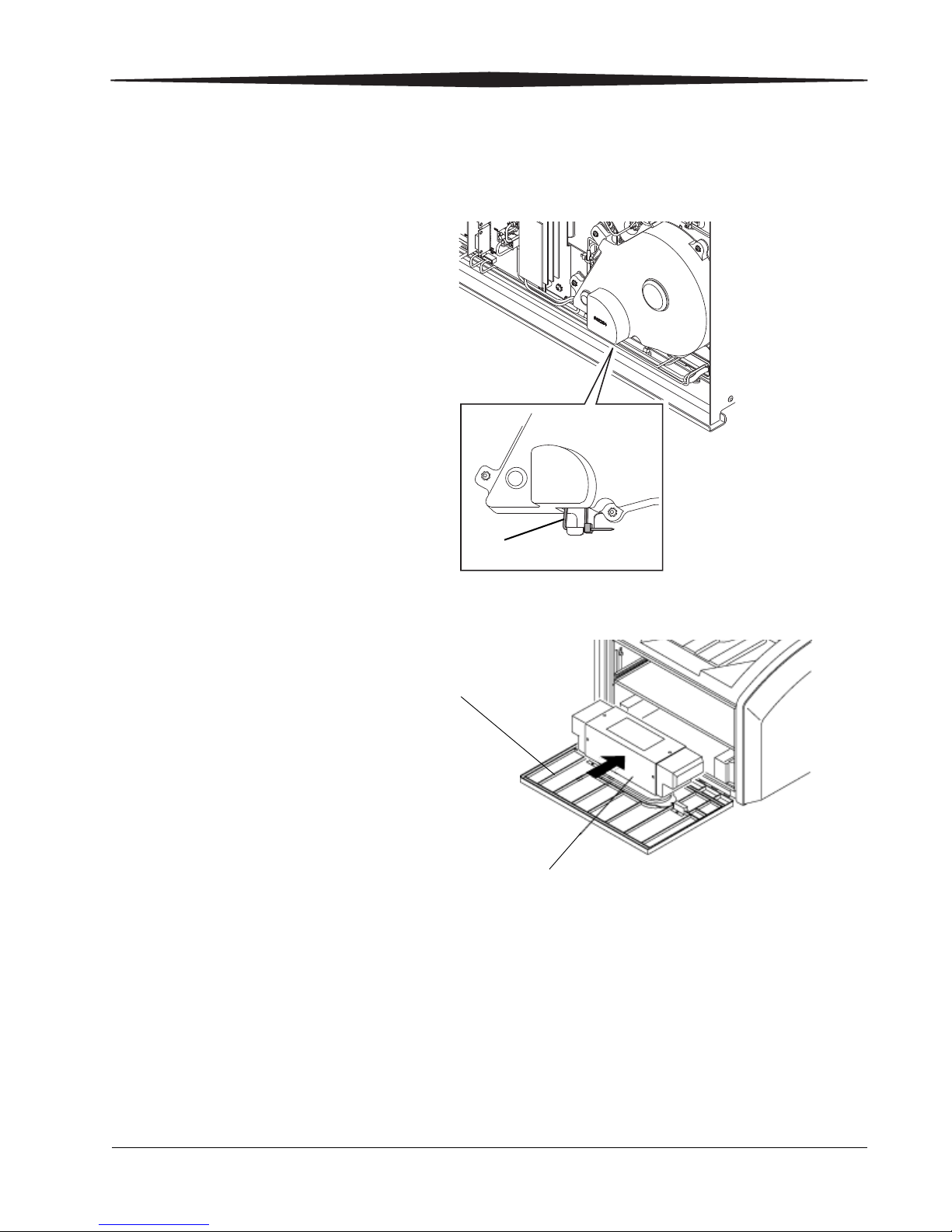
10. Behind the right cover, locate the tie wrap that fastens the exposure
H221_6030GC
Tie Wrap
Film Supply
Filter
transport belt. The tie wrap removes tension from the belt during
shipping. Cut and remove the tie wrap from the belt.
11. Install the deodorant filter.
12. Reinstall the right and top covers.
13. Close the film supply.
2015-04-17 9G7567_en 5
Connecting to electrical power
CAUTION:
RISK OF ELECTRIC SHOCK:
OR
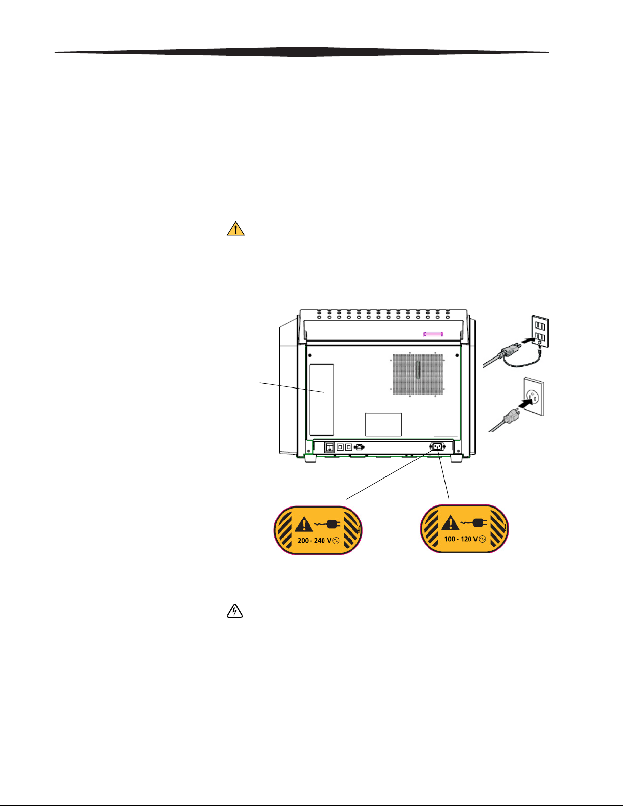
Laser
Imager
Back
Panel
1. Locate the power cord. The power cord must match the AC power
outlets at your site.
If you cannot use the power cord that is provided, obtain a suitable
power cord locally. You must use an agency-approved power cord
rated for adequate amperage with a plug type suitable for your
location. Contact your dealer if you need assistance.
2. Check that the voltage on the label over the power cord inlet
matches the AC voltage at your site.
If the voltage on the label does not match the AC voltage at
your site, do not continue with the installation. Contact your
dealer or qualified service provider.
Power cord inlet labels and connectors
6 9G7567_en 2015-04-17
3. Remove the power cord inlet label.
Dangerous voltage!
4. Connect the power cord to the:
• AC power connector on the laser imager.
• Building AC power outlet.
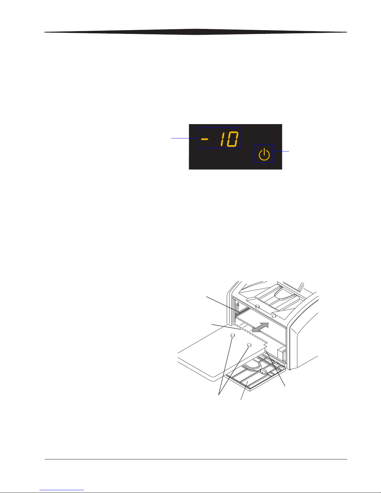
Applying power
The power symbol is
yellow and flashing
while the laser
imager warms up
A countdown to zero (0) indicates
how soon the laser imager will be
ready to print
Film Supply
1. Check that the film supply is closed.
2. To start the laser imager, press the power switch on the back of the
Warming up
NOTE: If the laser imager does not start, see “Troubleshooting” on page
Inserting a film cartridge
1. Open the film supply.
2. Insert the film cartridge. Align the cartridge with the label facing up
laser imager to on (|). Wait as the laser imager warms up. The
warm-up period might last up to 30 minutes. The display screen
shows the progress as the laser imager becomes ready to print.
The warm-up period varies depending on how long the laser imager
has been off and the ambient temperature.
12.
and the perforations to the front. Set the leading edge on the
cartridge guides, then slide the film cartridge into the laser imager to
engage the detents in the bottom of the cartridge.
Cartridge
Guide
Perforations
Leading Edge
Detents
H210_1020ACA
H210_1020AC
3. Close the film supply.
4. Check that the film count appears on the display screen.
NOTE: If a film count does not appear, see the Operation Manual for
2015-04-17 9G7567_en 7
help.
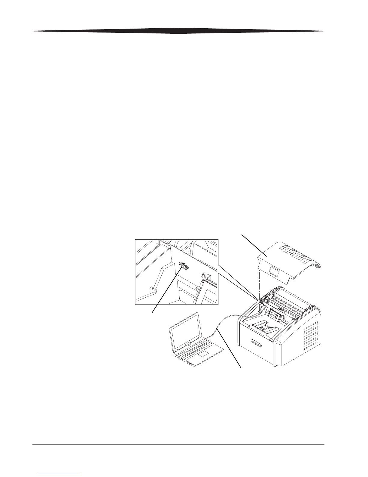
Configuring the laser imager
Service
Port
Top Cover
Crossover Cable
Setting up your
computer to
communicate with the
laser imager
Connecting your
computer to the laser
imager
Do this procedure at your computer.
1. Select Start>Settings>Network Connections.
NOTE: Depending on your operating system, this might be
Start>Settings>Network and Dial-up Connections.
2. Right-click Local Area Connection.
3. Select Properties.
4. Select Internet Protocol (TCP/IP).
5. Click Properties.
IMPORTANT: Remember or write down your current settings, as you
will reset your computer to these settings near the end of
the installation.
6. Select the option button next to Obtain an IP address
automatically.
7. Click OK.
8. Click OK.
8 9G7567_en 2015-04-17
H221_6031HC
1. Remove the laser imager’s top cover.
2. Using a crossover cable, connect your computer to the service port
on the laser imager.
3. Route the crossover cable so that it does not interfere with the top
cover when it is installed.
4. Reinstall the top cover.
Configuring
site-specific information
1. Start MICROSOFT INTERNET EXPLORER.
2. In the Address box, type: 192.168.0.1
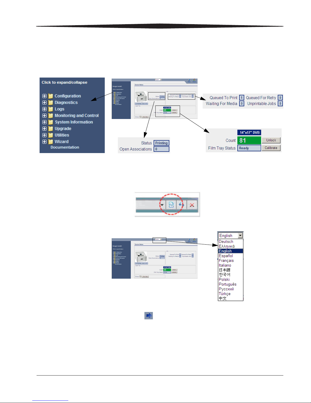
3. Click Go. The main screen for the Web Portal appears.
4. If you are using INTERNET EXPLORER 8, set the IE8 window to
compatibility view. Click the Compatibility View toolbar button. This
will correct some potential viewing issues with IE8. If the icon is not
on the toolbar, select Compatibility View from the Tools menu.
5. Select your language:
6. Select Wizards > Installation Assistant.
7. Click at the bottom of the screen. The Network Configuration
screen appears.
8. Enter:
•Host Name
• IP Address
• Subnet Mask
• Default Gateway
2015-04-17 9G7567_en 9

NOTE: This information should have been gathered in the
Pre-Installation Manual. If you need help, see your network
administrator.
9. Click Save.
10. Click . The Clock Configuration screen appears.
IMPORTANT: The system clock is set before the laser imager is
shipped to you. If the time zone is not correct, change it.
When you change the time zone, the time and date
display correctly.
11. Are the time zone, date, and time correct?
Ye s N o
Advance to step 13. Continue with the next step.
12. Will you set the clock manually, or does the site use a time server
for synchronization?
Manually Synchronization
Select the time zone.
a.
b. Edit the time if
needed.
c. Click Save.
a. Select the Enable Time
Synchronization check box.
b. In the IP Address field, type the
address of the time server to be
used for synchronization.
c. In the Period field, select the
synchronization period (how often
the clock is synchronized) from the
drop-down menu.
d. Select the time zone.
e. Click Save.
13. Click . The System Identification screen appears.
NOTE: Completing this screen is optional.
14. Enter the following information:
• Country Code
•Postal Code
• Hospital Name
• Department Name
• Device Location
15. Click Save.
16. Click to return to the main screen.
17. Select Utilities > Session, and then click Restart.
NOTE: Make sure to restart using these steps or the network
parameters will not be saved.
10 9G7567_en 2015-04-17
Wait for the laser imager to restart. The laser imager requires approximately
Laser Imager
Back Panel
30 minutes to warm up. After completing the warm-up cycle, the laser imager
may print a calibration film if the film cartridge requires it. While the laser
imager is warming up, continue with the next step.
Completing the installation
1. Connect the network cable to the:
• Network connector on the laser imager.
• Nearest building network connector.
2. After the laser imager has completed the warm-up cycle, send an image from
each modality that will print to the laser imager.
3. If the image quality must be improved for a modality, optimize the images
from that modality:
a. From the main screen, select Wizards > Image Quality.
b. Cancel all pending print jobs OR wait until all print jobs are printed.
c. Under Optimization Steps, click .
d. Send an image from the modality, and then click .
NOTE: The image does not print until you click the button.
NOTE: If none of the images are optimal for your site, call a qualified service
4. Disconnect the crossover cable and restore the settings to your computer if
Discarding excess material
2015-04-17 9G7567_en 11
When you are finished and the laser imager is operational, discard all excess
shipping materials in a manner suitable to local ordinances.
e. View the test print and visually select the optimal image.
f. Under Image Number, click to select the number of your optimal
image.
g. Under Optimization Steps, click again to continue.
h. Check for a “Passed” status near the bottom of the screen.
i. Send another image from the modality and check the print.
provider.
necessary.

Troubleshooting
CAUTION:
Laser imager does not
start
Never pull on the cord to disconnect the plug from the wall
outlet. Grasp the plug and pull to disconnect.
1. Press the power switch on the back of the laser imager off(0), and
then on (|), to restart the laser imager.
If this does not solve the problem, continue with step 2.
2. Disconnect the power cord from the wall outlet.
3. Check that the power cord is properly connected to the AC power
connector on the laser imager.
4. Plug the power cord into the wall outlet.
5. Check that the wall outlet is energized.
6. If the laser imager still does not start, contact your qualified service
provider.
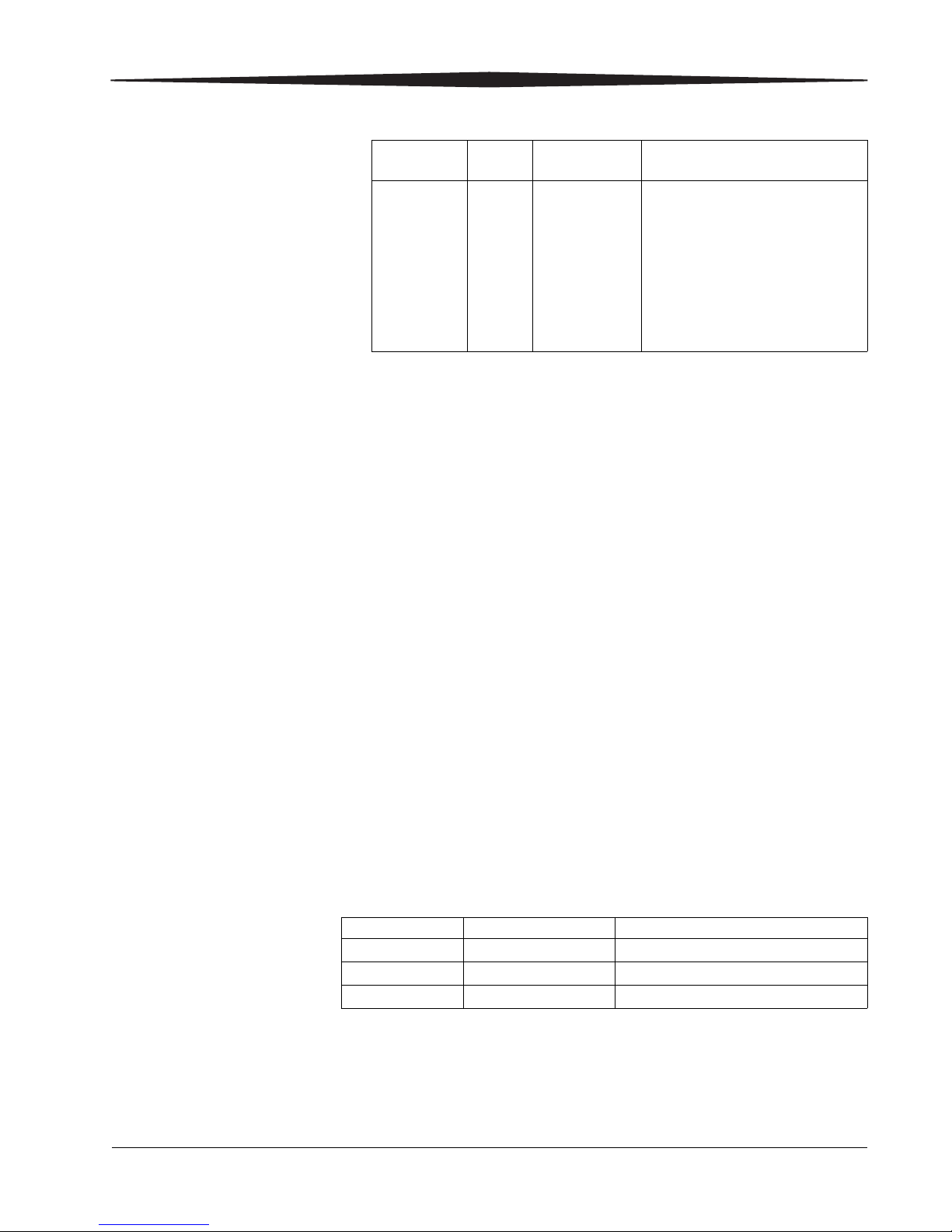
Error codes The following codes might appear during the installation. If so, see the
table to resolve them. For a complete list of error codes, see the
Operation Manual.
NOTE: As shown in the table, the same code appears as a 3-digit
number on the display screen and as a 5-digit number at the
Web Portal. See the Operation Manual for more information.
Display
Screen
Web
Portal
Web Portal
Message
Action
006 20006 Disconnected
or faulty
network cable
Check and reconnect the
network cable on both ends.
Try a different cable. Check
that the network is functioning
at your site.
If the error persists, call for
service.
209 20209 Laser Imager
Opened
During Self
Test
Close the cover. Restart the
laser imager.
If the error persists, call for
service.
701 20701 none Close the cover.
704 20704 none The network connection to the
laser imager has been lost.
Restart the laser imager.
12 9G7567_en 2015-04-17
Display
Screen
Web
Portal
Web Portal
Message
Action
175 21175 Rollback
Failed to
Engage
Cartridge
If the Pause symbol is on, press
it to cover the film cartridge.
When the Pause symbol stops
flashing, remove the film
cartridge from the laser imager.
Insert a different film cartridge
into the laser imager.
If the error persists, call for
service.
Publication History
2015-04-17 9G7567_en 13
Revision Date Reason for Change
A 2011-03-31 First release
B 2013-04-01 Updated the company name
C 2015-04-17 Added the rollback retainer

KONICA MINOLTA, INC.
1 Sakura-machi, Hino-shi, Tokyo, 191-8511, Japan
KONICA MINOLTA, INC., 2015
©
Pub No. 9G7567_en
Rev C
Operation Manual
Publication No. 9G7564_en
2013-04-01

All rights reserved. No part of this manual may be reproduced or copied in
any form by any mean graphic, electronic, or mechanical, including
photocopying, typing, or information retrieval systems without written
permission.

Contents
1Overview
How the Imager Works ................................................................................................................. 1-4
Print Sequence ......................................................................................................................... 1-4
Film Sizes .................................................................................................................................. 1-5
Automatic Image Quality and Processing ..............................................................................1-5
Configure and Monitor the System (Using the Web Portal) ................................................. 1-5
Agency Compliance ................................................................................................................. 1-6
Operation Manual Conventions ............................................................................................. 1-6
2 Basic Operating Tasks
Understanding the Display Screen ...............................................................................................2-2
Turning the Power On and Off .....................................................................................................2-4
Emergency Shutdown or Power Loss ........................................................................................... 2-4
Restarting the Imager ................................................................................................................... 2-5
Film Cartridge Information ...........................................................................................................2-6
Insert a New Film Cartridge ..........................................................................................................2-7
Load a Different Film Size to Match a Print Request ..................................................................2-8
Delete Pending Jobs ...................................................................................................................... 2-9
Make a Test Print ........................................................................................................................... 2-9
Calibrate the Imager for the Installed Film ................................................................................2-10
Open or Remove a Cover ............................................................................................................2-11
Additional Functionality with the Web Portal .......................................................................... 2-12
Access the Web Portal ........................................................................................................... 2-12
3 Maintenance and Troubleshooting
Overview: Status and Error Messages and Codes ........................................................................ 3-1
Preventive Maintenance ............................................................................................................... 3-2
About the Filter ....................................................................................................................... 3-2
Replace the Filter .....................................................................................................................3-2
550 Code and Maintenance Symbol ....................................................................................... 3-3
Error Indicators on the Display Screen .........................................................................................3-4
Using the Web Portal to Gain More Information on Errors ....................................................... 3-5
Subsystem Error Codes and Messages .......................................................................................... 3-6
DICOM (Digital Imaging and Communications in Medicine) ................................................ 3-6
Printer ....................................................................................................................................... 3-7
Film Cartridge .......................................................................................................................... 3-8
Job Manager ............................................................................................................................ 3-9
9G7564_en | 2013-04-01 i

Condition Codes .......................................................................................................................... 3-10
Film Jam Indication and Areas .................................................................................................... 3-16
Clear Film Jam Code 116 / Jam in Area 1 .............................................................................3-18
Clear Film Jam Code 323 / Jam in Area 2 .............................................................................3-18
Clear Film Jam Code 324 or 325 / Jam in Area 2 ..................................................................3-19
Clear Film Jam Code 326 / Jam in Area 2 or 3 ...................................................................... 3-20
Clear Film Jam Code 543 or 544 / Jam in Area 3 ..................................................................3-21
Display Screen is Not Functional .................................................................................................3-21
Call for Support ...........................................................................................................................3-21
4 Film Technical Information
Spectral Sensitivity .........................................................................................................................4-1
Image Quality ................................................................................................................................4-1
Environmental Impact ................................................................................................................... 4-2
Undeveloped Film Handling and Storage ....................................................................................4-2
Developed Film Handling and Archival ........................................................................................4-3
Exposing Film to Moisture ............................................................................................................ 4-3
Odor Dissipation ............................................................................................................................ 4-4
Heat Dissipation ............................................................................................................................. 4-4
Film Recycling ................................................................................................................................4-4
5 Specifications
Equipment Specifications .............................................................................................................. 5-1
Operating Space Requirements .................................................................................................... 5-1
Environmental Requirements ....................................................................................................... 5-1
Environmental Effects .............................................................................................................5-2
Power Requirements ............................................................................................................... 5-2
Network Requirements ...........................................................................................................5-2
6 Publication History
ii 9G7564_en | 2013-04-01
1
Important
Overview
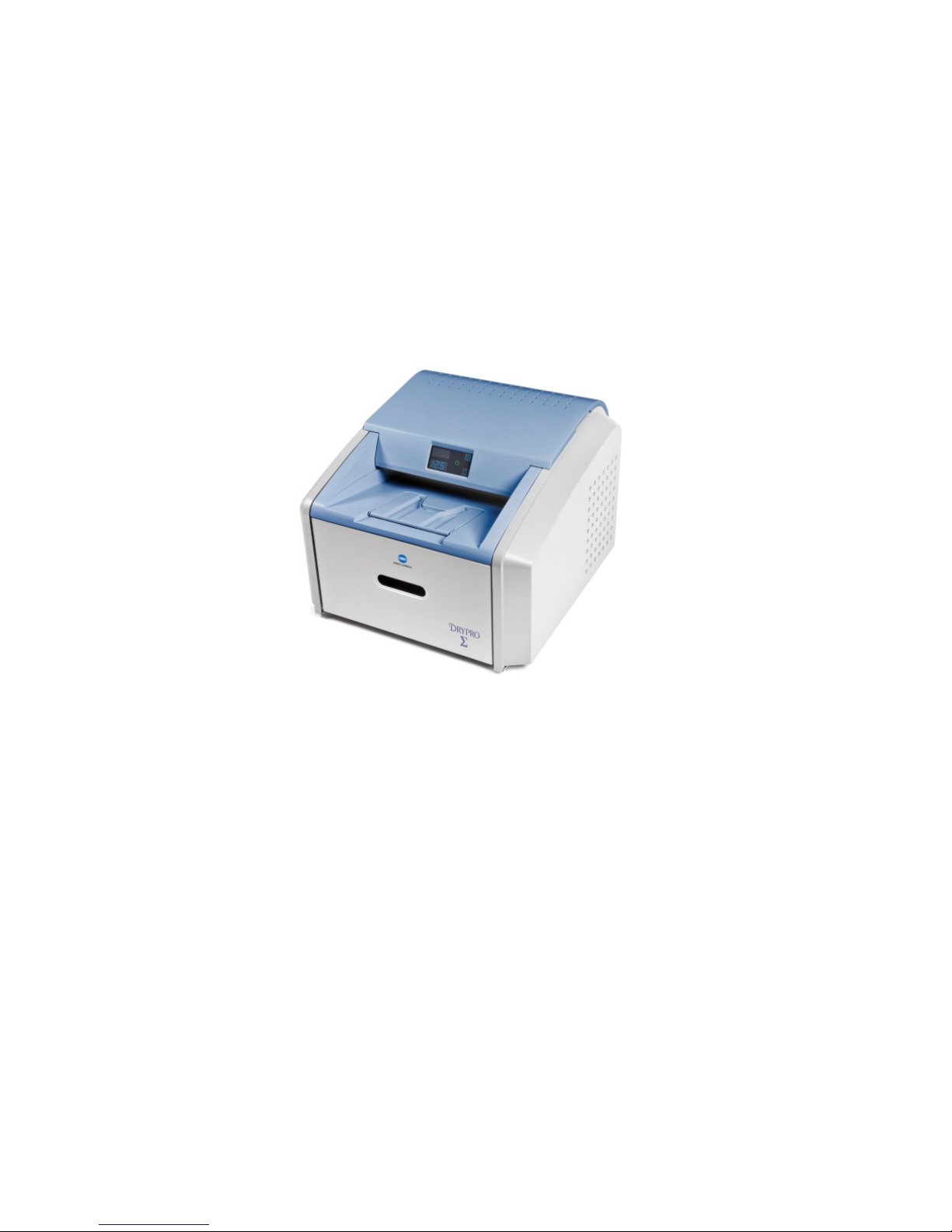
The Laser Imaging System is a continuous-tone laser imager with an internal
photothermographic film processor. Heat, rather than photo chemicals, is used to
develop the film. This easy-to-use and reliable imager provides high quality prints. Use
the prints from this system for:
• Diagnostic purposes to determine patient treatments
• Referral, sharing, or educational purposes
The system receives and prints from image sources such as medical electrical equipment
(modalities) and workstations over the network. You can send print jobs simultaneously
from multiple image sources. The open design lets you connect to modalities of all types
and vendors.
Install the printing system in a secure location to protect patient privacy rights if required by local
regulations.
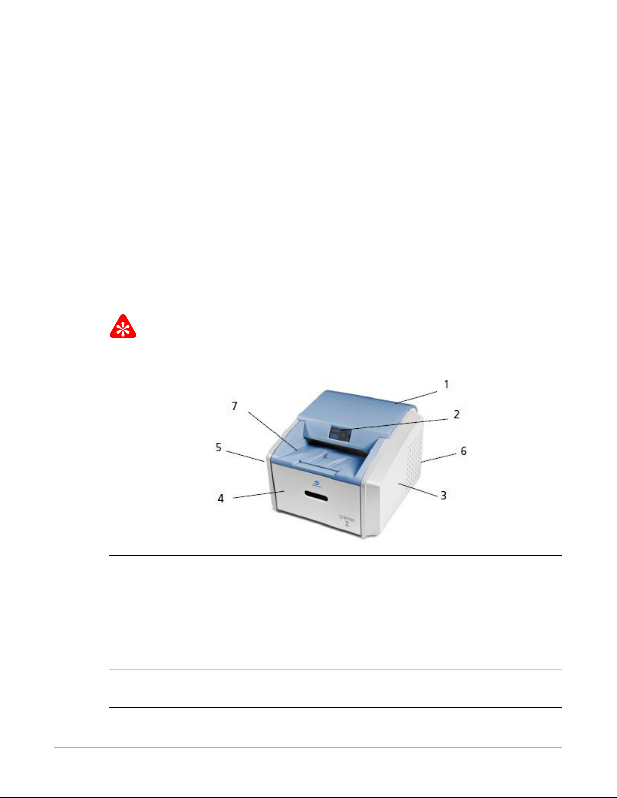
1 Top cover. Covers the processor rollers. The top cover is interlocked.
2 Display screen. Your interface to the imager. Provides status and error information.
3 Right cover. Protects sensitive electronic equipment. The right cover is only accessed by
service personnel.
4 Film supply cover. Covers the film supply, which supports four film sizes.
5 Left cover. You might remove the left cover to clear an occasional film jam. The left
cover is interlocked.
9G7564_en | 2013-04-01 1–1
Overview
6 Power switch. The power switch is on the back.
7 Exit tray. Extend the exit tray to hold large film (35 x 43 cm, or 14 x 17 in.) as it finishes
printing. It can hold up to 50 processed sheets of film.
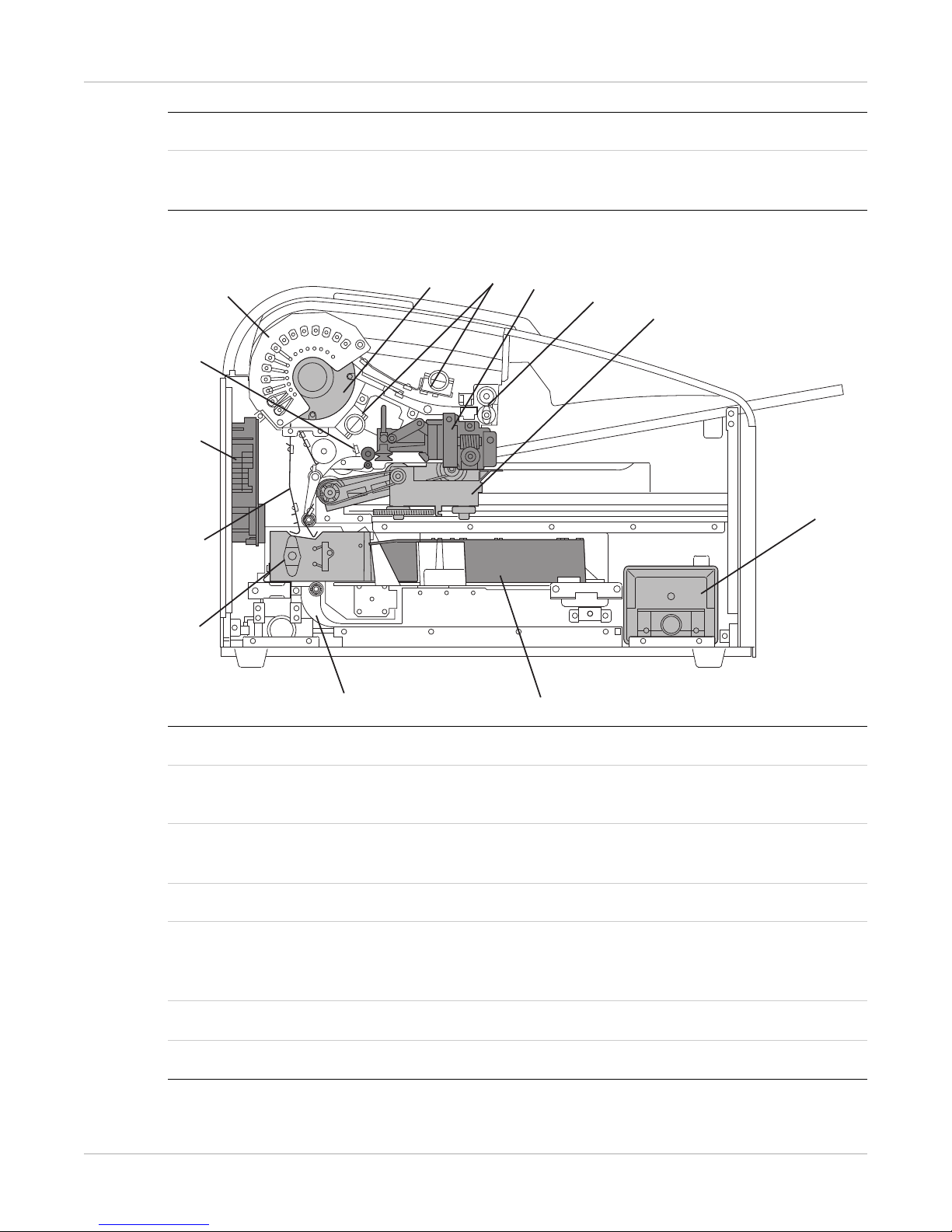
Major Internal Assemblies
5
6
4
3
2
1
13
7
8
12
9
10
11
H210_1012HC
1 Exposure transport. Moves the film past the scanning laser beam.
2 Transport guides. Orient and center the film while moving the film from the supply to
the imaging portion of the imager.
3 DICOM Raster Engine (DRE). A computer board that receives, processes, and man-
ages the images.
4 Feed rollers. Move the film through the imager.
5 Processor rollers. The processor uses heat to develop the image written onto the film
by the laser in the optics module. The rollers move the film through the processor
assembly, holding the film against the processor drum.
6 Processor drum. Provides the heat that processes the image on the film.
7 Airflow manifolds. Remove heat and processing odors from the processor assembly.
1–2 9G7564_en | 2013-04-01

Overview
8 Pickup assembly. Lifts a single sheet of film from the supply cartridge and feeds it into
the rollers.
9 Exit rollers. Moves the film from the processor area to the exit tray.
10 Rollback assembly. Rolls the film cartridge cover back so the pickup assembly can lift
the film. When the imager is not printing, the cover is closed over the film cartridge to
protect the film from light.
11 Deodorant filter. Absorbs the odors caused by heat processing.
12 Optics module. Writes the image onto the film while the film is moved through the
exposure transport.
13 Accumulator. The film feeds into the accumulator as it is imaged. When imaging is
complete, the film is sent from the accumulator up to the processor assembly where the
heat is applied to process the image.
9G7564_en | 2013-04-01 1–3
Overview
How the Imager Works
The imager receives, processes, manages, and prints the images on film. The imager has
limited storage to hold a small number of digital images. As images are received for
printing, they are stored in memory, placed in a sequential print queue, and are printed
in order. The imager can continue to accept incoming print jobs even if temporarily
unable to print (if the film supply is empty, etc.).
During normal operation, the imager requires very little attention. It prints automatically
in response to print requests from the configured image sources. Information sent with
the images by the image source, such as film type and size and image quality settings, is
applied unless you set the imager to override information that comes from the image
source.
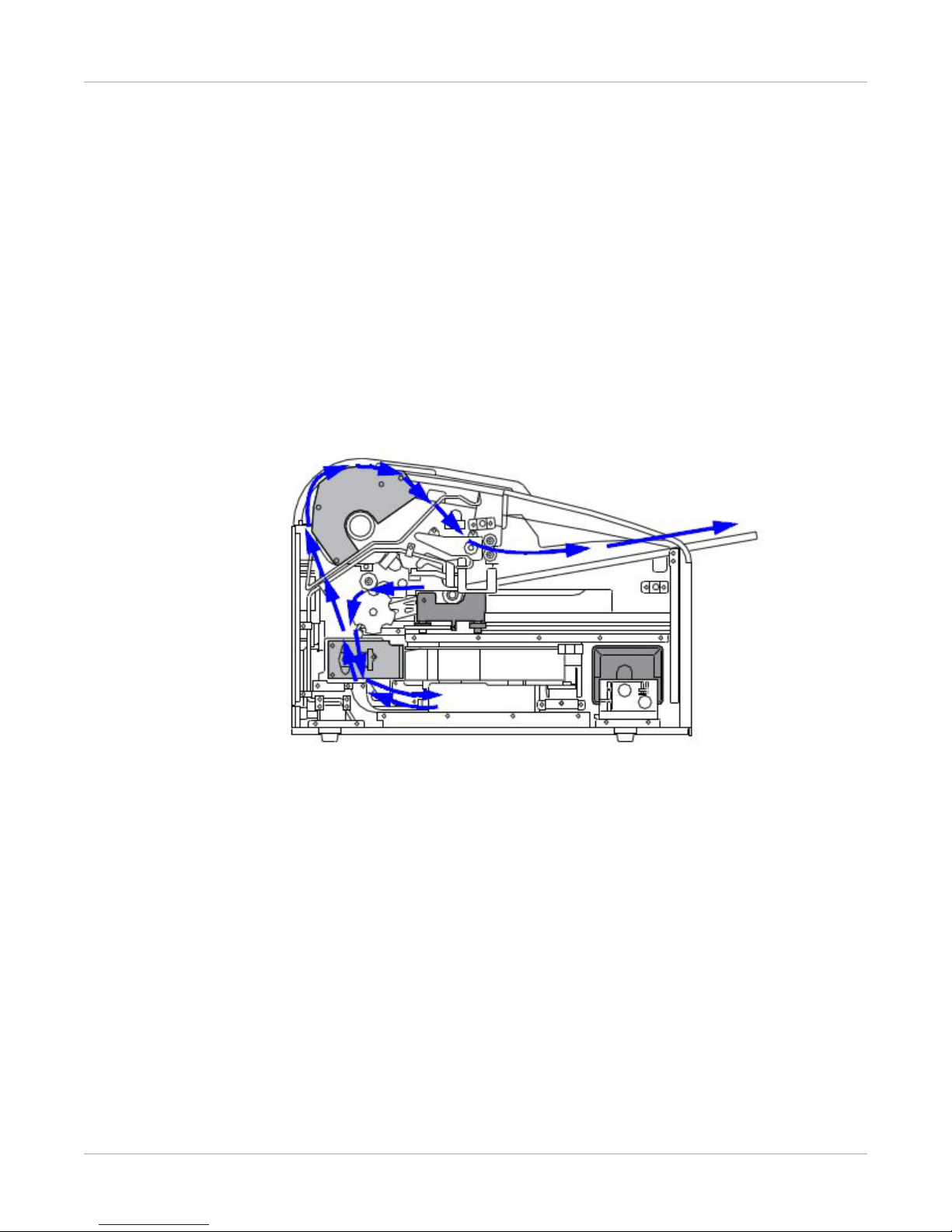
Print Sequence
Each time the imager receives a print request, the following print sequence occurs. The
blue arrows show the film path.
1. Suction cups in the pickup area lift a single sheet of film out of the supply ca
and
feed the film into the transport rollers.
2. The transport rollers move the film down into the exposure transport area.
3. The film moves down during imaging (as the optics module writes the image on
film),
reverses direction at the conclusion of imaging, and then the film moves up
the processor.
4.
As the film passes over the processor drum, the heat generate
the film.
5.
The exit rollers move the developed film to the
1–4 9G7564_en | 2013-04-01
rtridge
to
into
d by the drum develops
exit tray.

Film Sizes
The imager supports four sizes:
• 35 x 43 cm (14 x 17 in.)
• 28 x 35 cm (11 x 14 in.)
• 25 x 30 cm (10 x 12 in.)
• 20 x 25 cm (8 x 10 in.)
For the specific films that are supported, see the Publications Cover Page.
Automatic Image Quality and Processing
An internal densitometer enables the imager to automatically adjust image processing
parameters (Automatic Image Quality Control, or AIQC) to produce an optimal image.
The imager adjusts these parameters each time it prints a calibration film.
A calibration film is printed when:
• The film tray is inserted in the imager with film of a new lot number.
• You request a calibration film at the display screen or the Web Portal.
Overview
• A film cartridge is inserted into the imager for which a current calibrat
stored.
Related topics
Calibrate the Imager for the Installed Film
Configure and Monitor the System (Using the Web Portal)
The Web Portal is your interface to additional features. In addition to the installation and
setup of your system, you can view and manage the imager's connections over the
network, configure features, view error messages, and access general status information
at the Web Portal. You can also check film count, film size, and film type.
Related topics
Access the Web Portal
ion is not
9G7564_en | 2013-04-01 1–5

Overview
Note
Important
Caution
DANGER
Note
Agency Compliance
See the Safety Manual.
Operation Manual Conventions
The following special messages emphasize information or indicate potential risks to
personnel or equipment.
Notes provide additional information, such as expanded explanations, hints, or reminders.
Important notes highlight critical policy information that affects how you use this guide and this
product.
Cautions point out procedures that you must follow precisely to avoid damage to the system or
any of its components, loss of data, or corruption of files in software applications.
Danger identifies procedures that you must follow precisely to avoid injury to yourself or others.
Laser warnings warn personnel that access to laser radiation is possible and all personnel must
avoid direct exposure to the beam.
1–6 9G7564_en | 2013-04-01

2
Basic Operating Tasks
During normal operation, the imager receives and automatically prints images sent by
modalities over a network. Very little interaction is required. You may do the following:
• Turn the power on (|) and off (0).
• Load film cartridges.
• Monitor the display screen for status and operating conditions.
Sometimes it will be necessary to perform preventive maintenance, filter replacement,
and other corrective actions such as a restart.
You also may access the Web Portal to perform additional configuration, optimize image
quality, or do troubleshooting tasks.
Related topics
Maintenance and Troubleshooting
Additional Functionality with the Web Portal
9G7564_en | 2013-04-01 2–1
Basic Operating Tasks
Note
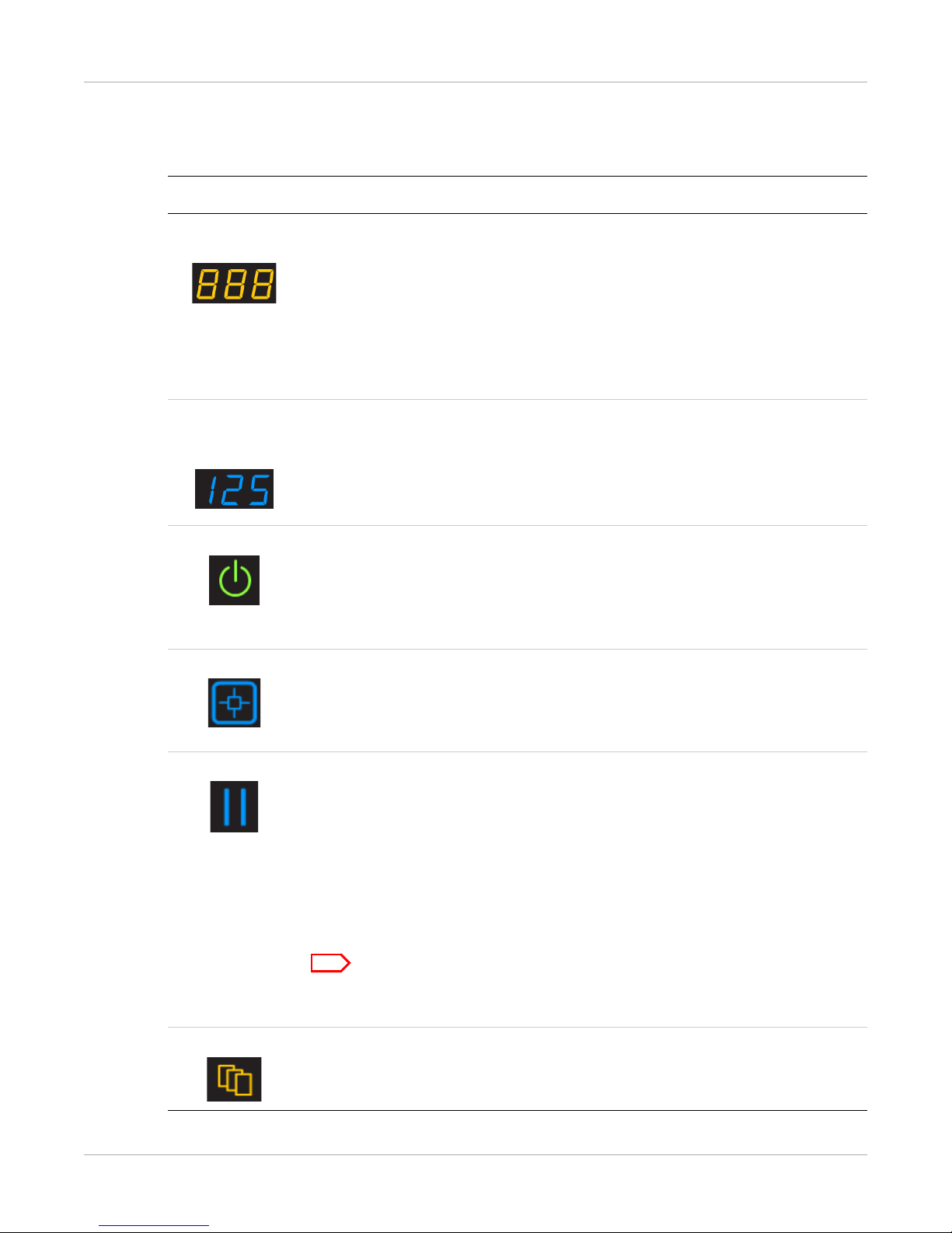
Understanding the Display Screen
The display screen communicates the status of the imager.
Symbol or code Description
Top left of the
display screen:
Error or status code. The 3-digit code displays when the error or status condition is present. If the imager is on and a 3-digit code does not display, the
imager is operating normally.
If a different film size has been requested than what is installed, the
requested film size displays.
When the imager is starting, a countdown displays the number of minutes
until the imager will be ready to print (for example, -4 means 4 minutes
until the imager will be ready to print).
Lower left of
the display
screen:
Film count. Displays the number of films that are remaining in the film cartridge.
The loaded film size also displays in this location.
If a blue number does not display while the imager is powered on, the film
cartridge is not inserted (or not fully inserted) into the imager.
Power When the symbol is green, the power is on and the imager is ready to print.
The symbol flashes while the imager is while processing, calibrating, or
making a test print.
When the symbol is yellow, the imager is not ready to print. Examples are
when the imager is warming up or when the film cartridge is empty.
Calibrate Press to initiate film calibration. The symbol flashes while the calibration is
in process.
Calibration might be needed if the symbol is on and code 624, 631, or 632
appears.
Pause During normal operation, the symbol is off. (See exceptions in the note
below.) When the film cartridge cover is open, the symbol is on. To avoid
exposing the film to light, do not open the film supply until the symbol is
off.
If the Pause symbol is on, you can press the symbol to temporarily pause
printing. Any jobs in progress finish printing, then the film cartridge cover
closes.
Wait until the Pause symbol is off for cartridge replacement, etc.
The Pause symbol is on while the imager is processing images or test prints
and during calibration.
Film Size When the symbol appears, the requested job requires a different film size.
You can also cancel all pending print jobs that require an unavailable media
size.
2–2 9G7564_en | 2013-04-01

Basic Operating Tasks
Symbol or code Description
Restart Restart the imager. An error code also displays.
Film Jam Film is jammed. The error code confirms the film jam and gives direction on
where to find the film inside the imager.
Maintenance Preventive maintenance is required. Check the error code to learn what
action to take.
Related topics
Maintenance and Troubleshooting
Load a Different Film Size to Match a Print Request
Calibrate the Imager for the Installed Film
Delete Pending Jobs
Restarting the Imager
Film Jam Indication and Areas
Preventive Maintenance
9G7564_en | 2013-04-01 2–3
 Loading...