

Konica Minolta DRYPRO Model 793 Operation Manual
LASER IMAGER
DRYPRO MODEL 793
OPERATION MANUAL
CODE NO.
0792 (UL), 0791 (CE)
No. 26-2, Nishishinjuku 1-chome, Shinjuku-ku, Tokyo 163-0512, Japan

Table of Contents
Foreword.............................................................. 1
About This Manual .............................................. 3
Ch.1 Safety Precautions & Warnings ................ 7
Ch.2 Product Outline .......................................... 17
2-1 Name of Each Component ................................. 18
2-2 Internal Structure ................................................ 25
Ch.3 Operation .................................................... 27
3-1 Operation Panel.................................................. 28
3-2 Startup ................................................................ 30
3-3 Shutdown............................................................ 31
3-4 Film Loading ....................................................... 35
3-5 Sleep Mode......................................................... 40
3-6 Changing the Film Size and Film Type............... 42
Ch.4 Maintenance Mode ..................................... 47
4-1 Maintenance Mode Overview ............................. 48
4-2 Switching to the Menu Mode .............................. 50
4-3 Switching to the Maintenance Mode................... 52
4-4 Operation of Each Menu..................................... 56
4-4-1 PRINT QUEUE INFO............................... 56
4-4-2 PREVIOUS PRINT................................... 57
4-4-3 QUEUE CLEAR ....................................... 61
4-4-4 TEST PRINT ............................................ 62
4-4-5 CALIBRATION ......................................... 64
4-4-6 MAMMO QC PRINT................................. 66
4-4-7 PRINT CONDITION ................................. 68
4-4-8 LUT SETUP ............................................. 73
4-4-9 FILM DATA .............................................. 78
4-4-10 FILM SETUP............................................ 80
4-4-11 START TIMER......................................... 82
4-4-12 TIME SET ................................................ 84
4-4-13 TOUCH PANEL ....................................... 86
4-4-14 SLEEP MODE.......................................... 88
4-4-15 SORTER SETUP..................................... 90
4-4-16 FRONT COVER OPEN............................ 93
4-4-17 SYSTEM RESET..................................... 94
4-4-18 DUST CLEANING.................................... 95
Ch.5 Web Maintenance Mode ............................ 99
5-1 Overview of Web Maintenance Mode................. 100
5-2 Startup/Shutdown of Web Maintenance Mode ... 103
5-3 Menu Items of Web Maintenance Mode ............. 107
5-3-1 STATUS................................................... 107
5-3-2 QUEUE LIST............................................ 108
5-3-3 PREVIOUS PRINT................................... 109
5-3-4 QUEUE CLEAR ....................................... 110
5-3-5 PRINT CONDITION ................................. 111
5-3-6 LUT SETUP ............................................. 113
5-3-7 FILM DATA .............................................. 115
5-3-8 FILM SETUP............................................ 116
5-3-9 START TIMER ......................................... 117
5-3-10 TIME SET ................................................ 118
5-3-11 SLEEP MODE.......................................... 119
5-3-12 SORTER SETUP..................................... 120
5-3-13 SYSTEM RESET..................................... 121
Ch.6 Troubleshooting ......................................... 123
6-1 Error Message and Reaction .............................. 124
6-2 Error Reset ......................................................... 126
6-3 Resolving the Film Jam ...................................... 128
6-3-1 Film Jam in Cooling Unit .......................... 129
6-3-2 Film Jam in the Descent Transport Unit... 132
6-3-3 Film Jam in the Elevator Transport Unit... 136
6-3-4 Film Jam in the Supply Tray .................... 138
6-3-5 Film Jam in the Sorter Transport unit....... 139
Ch.7 Care & Maintenance ................................... 139
7-1 Periodic Maintenance and Inspection................. 140
7-2 Maintenance/Inspection Schedule...................... 146
7-3
Display and Check of the Maintenance & Inspection
.. 147
Specifications...................................................... 149

< 1 >
DRYPRO Vstage MODEL 793 Operation Manual Ver.1.01 2005.1
We would like to thank you for purchasing Laser Imager DRYPRO Vstage MODEL 793
(hereinafter referred to as DRYPRO 793).
DRYPRO MODEL 793 is a laser imager which realized a complete dry process, devel-
oped by considering the environment and operability, while maintaining high perfor-
mance and high image quality.
In this manual, safety precautions and operational procedures are described to allow the
users of the DRYPRO 793 to be fully familiarized with the potential of the device. The
manual should be at all times be kept in a readily accessible place for easy reference.
Should you loose this manual, please contact your Service Representative for a new
one.
Foreword

Foreword
< 2 >
DRYPRO Vstage MODEL 793 Operation Manual Ver.1.01 2005.1
Features
DRYPRO MODEL 793 is a laser imager which realized a complete dry process, developed by consid-
ering the environment and operability, while maintaining high performance and high image quality.
High-quality Image
1) Realizing super-sharpened images with the pixel size of 43.75 µm and 25µm as well as
capability of mammography.
2) Films that are most suitable for the imager and CR are newly developed.
3) Supporting 12-bit image input
4) Rendering high-quality images with advanced image interpolation processing technology
5) Built-in auto density control function for stabled image output.
Operation environment
1)Shortening waiting time for output by high-speed processing capability. (120 sheets / hour)
2) Maximum 3 CH of input tray, including 8"x10" and 10"x12".
Imaging environment
Capability of direct connection to diagnostic devices with DICOM communications secures
expandability on the open network even in the future.
Notes
(1) Unauthorized reproduction of this manual in whole or in part is prohibited.
(2) The content of this manual is subject to change without prior notice.
(3) Should any discrepancies, errors or omissions be discovered, KONICA MINOLTA should be contacted.
(4) Notwithstanding item(3) above, KONICA MINOLTA shall accept no responsibility of any claims made against loss or
loss of profits arising from use of the product.
Be sure to observe the following in order to prevent any danger.
1.NEVER remove the external and internal covers with a screwdriver, and others.
2.NEVER perform any operations, adjustments, or actions other than the specified in this Operation Manual; other-
wise, you may be exposed to dangerous radiation.
3.If any problem occurs in this device, contact your Service Representative. NEVER use the troubled device as it is
dangerous. Note that a laser tube is incorporated in this device, and direct exposure of eye or skin to the laser beam
may result in injury. Also the device contains an assembly using a high voltage. Due case should be taken not to
suffer from electrocution by touching this assembly.

< 3 >
DRYPRO Vstage MODEL 793 Operation Manual Ver.1.01 2005.1
About This
Manual
Be sure to read this chapter before using this
manual so that the manual can be fully utilized.

About This Manual
< 4 >
DRYPRO Vstage MODEL 793 Operation Manual Ver.1.01 2005.1
Chapter1 Safety Precautions & Warnings
When using the DRYPRO 793, the cautions detailed in this chap-
ter must be strictly followed in order to safely use the device.
Chapter2 Product Outline
The product outline of DRYPRO 793 is described in this chapter.
Chapter3 Operation
The operation of DRYPRO 793 is described in this chapter.
Chapter4 Maintenance Mode
This chapter describes the Maintenance Mode of the DRYPRO
793.
Chapter5 WEB Maintenance Mode
This chapter describes the WEB Maintenance Mode with which
the DRYPRO 793 can be maintenanced from external PC.
Chapter6 Troubleshooting
This chapter describes typical methods of trouble shooting and
the error message list displayed on DRYPRO 793.
Chapter8 Care & Maintenance
This chapter details the procedure for care and maintenance of
the DRYPRO 793.
Specifications Specifications of the DRYPRO 793 are described in this para-
graph.
Index The index describes special terminology used in the DRYPRO
793 Operation Manual.
Structure of this manual
This manual consists of the chapters listed below.
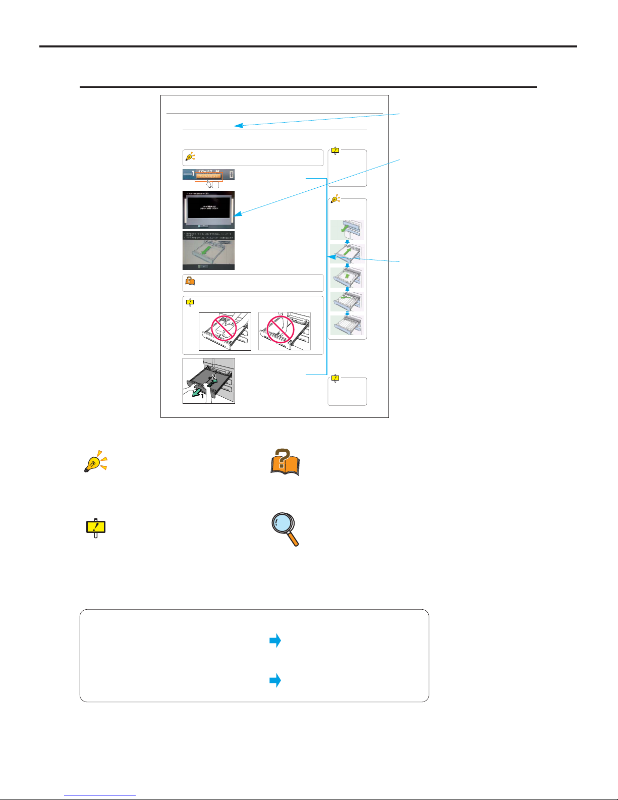
How to use this manual
About This Manual
< 5 >
DRYPRO Vstage MODEL 793 Operation Manual Ver.1.01 2005.1
Parenthesis in a sentence.
The word in this mark shows that it is displayed in the touch panel of the CS-2
operation unit.
The word in this mark shows that it is the
name of the button to be pushed or
touched.
Ex. "Ready"
Ex. [Complete] Button
Ch.3 Operation
< 35 >
DRYPRO Vstage MODEL 793 Operation Manual Ver.0.01 2004.10
3-4 Film Loading
When the supply tray becomes empty, a beep sound is released, followed by the [Film Set] button that is newly displayed in the
message column of the Operation Panel. (Beep sound can be selected from "Silent", "Single" and "Continuous" at the time of
installation) When this button is displayed, follow the procedures shown below to load the film package in the supply tray.
The DRYPRO 793 can receive the print data from the diagnostic device while it is in
film loading operation. The print data received during film loading will be printed after
the film loading is completed.
When a film is in printing process, Supply
Tray cannot be pulled
out until that film has
been printed. This may
take maximum 95 sec.
1 Touch the [Film Set] button.
- A message indicating that the tray is being pulled out.
- Supply tray pops out a few centimeters, and the animation
showing how to load the film package (pull out of the tray
~ removal of the sandwich paper and light-proof package)
will be displayed.
Do not put anything or lean on the Supply Tray while it is pulled out. Doing so will
damage the Supply Tray.
1
2 Gently and fully pull out the Supply Tray to its
end. (1 in the left fig.)
3 Fully open the Supply Shutter. (2 in the left fig.)
Shutter cannot be
opened if the Supply
Tray is not fully pulled
out.
Animation for "pull out
of the tray ~ removal of
the sandwich paper"
Sandwich Paper
One sheet of sandwich paper is always contained in a film package, and helps protect
the films from folding.
Hint
Points to be noted.
Technical Term
Technical terms are
explained.
Reference
Shows reference pages or
sections.
See the page for more
details.
Title
This title stands for the
general meanings for
the descriptions.
Display
Display with the operational procedure is
shown.
Operation Procedure
Operation procedure is
explained in order.
Caution
Cautions for operating the
machine.
Details should be carefully
noted.
Page Layout

About This Manual
< 6 >
DRYPRO Vstage MODEL 793 Operation Manual Ver.1.01 2005.1

< 7 >
DRYPRO Vstage MODEL 793 Operation Manual Ver.1.01 2005.1
When using the DRYPRO 793, the cautions
detailed in this chapter must be strictly followed in
order to safely use the device.
Safety
Precautions &
Warnings
1
Chap.
Ch.1 Safety Precautions & Warnings
< 8 >
DRYPRO Vstage MODEL 793 Operation Manual Ver.1.01 2005.1
This is the safety alert symbol and is intended to draw the attention of the user to potential dangers to the user
him/herself or to others that may arise during the use or operation of this system.
These messages must be read thoroughly and strictly observed.
All safety related precautions should be carefully read and fully understood before proceeding with assembly or
usage of this system.
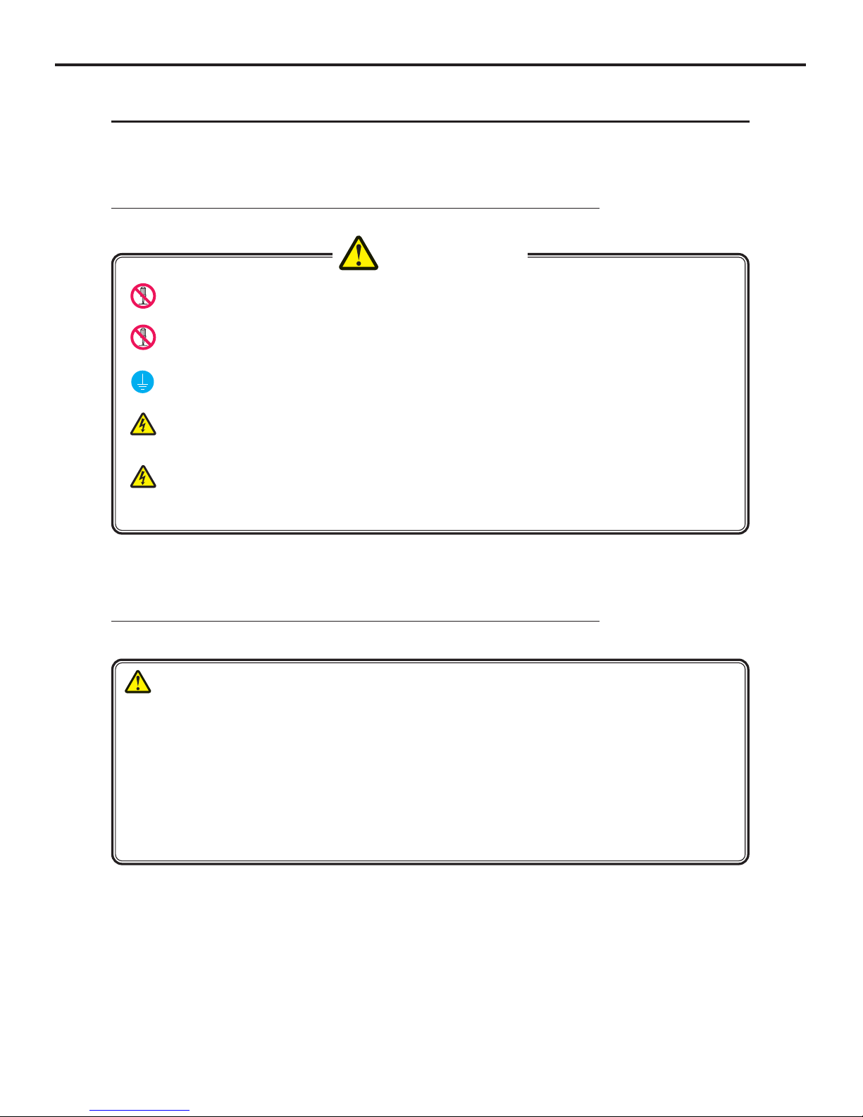
Safety Alert Symbol
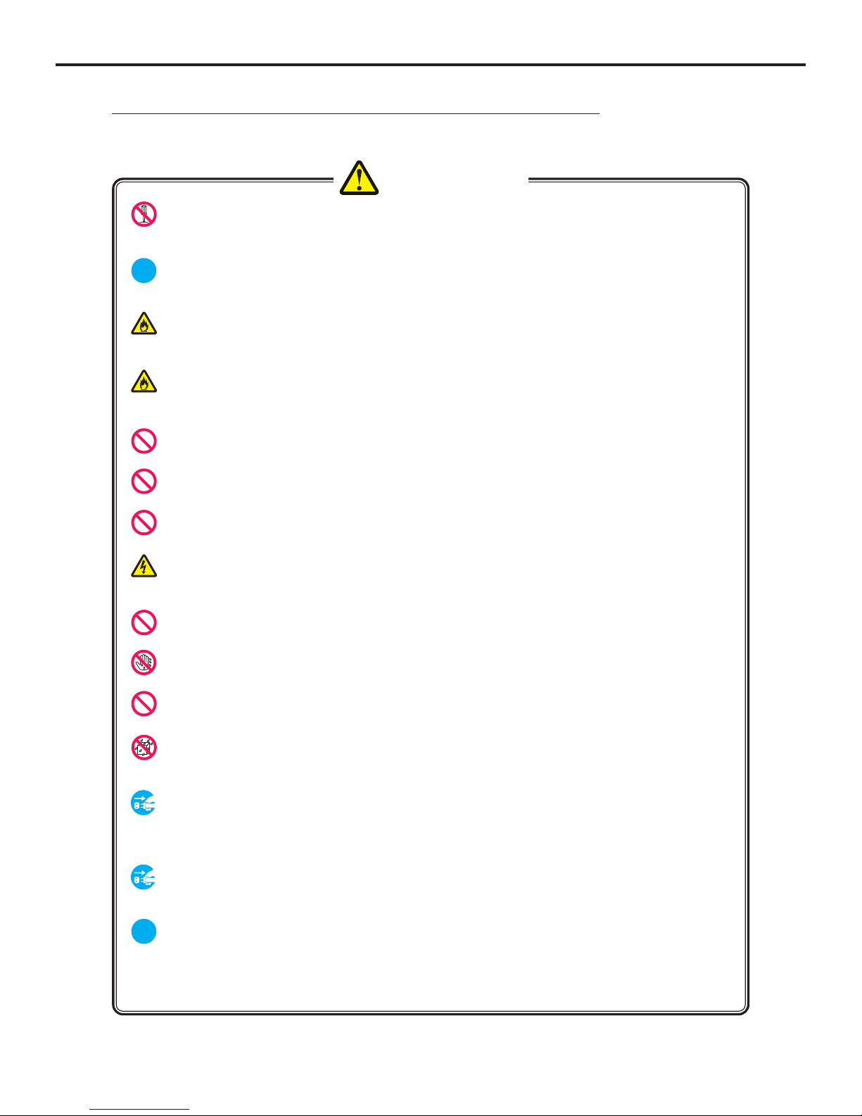
●
Symbols indicating the need for caution (including danger and warnings)
● Symbols indicating prohibited acts
● Symbols indicating essential acts (compulsory or indicated acts)
● Other Symbols
Description of Graphic Symbols
Normal Caution Danger of Fire
Prohibited
AC Voltage
(Power Supply)
Ground
Danger of High
Temperature
Danger of
Rotation
Main Power
Supply OFF
Main Power
Supply ON
Main Power
Standby
Remove the plug from
the power outlet
Do not touch Do not disassemble Do not touch
with wet hand
Mobile
Prohibited
Multi-Leads
Prohibited
Do not expose
to moisture
Danger of
Electrocution
Alert and Symbol Marks
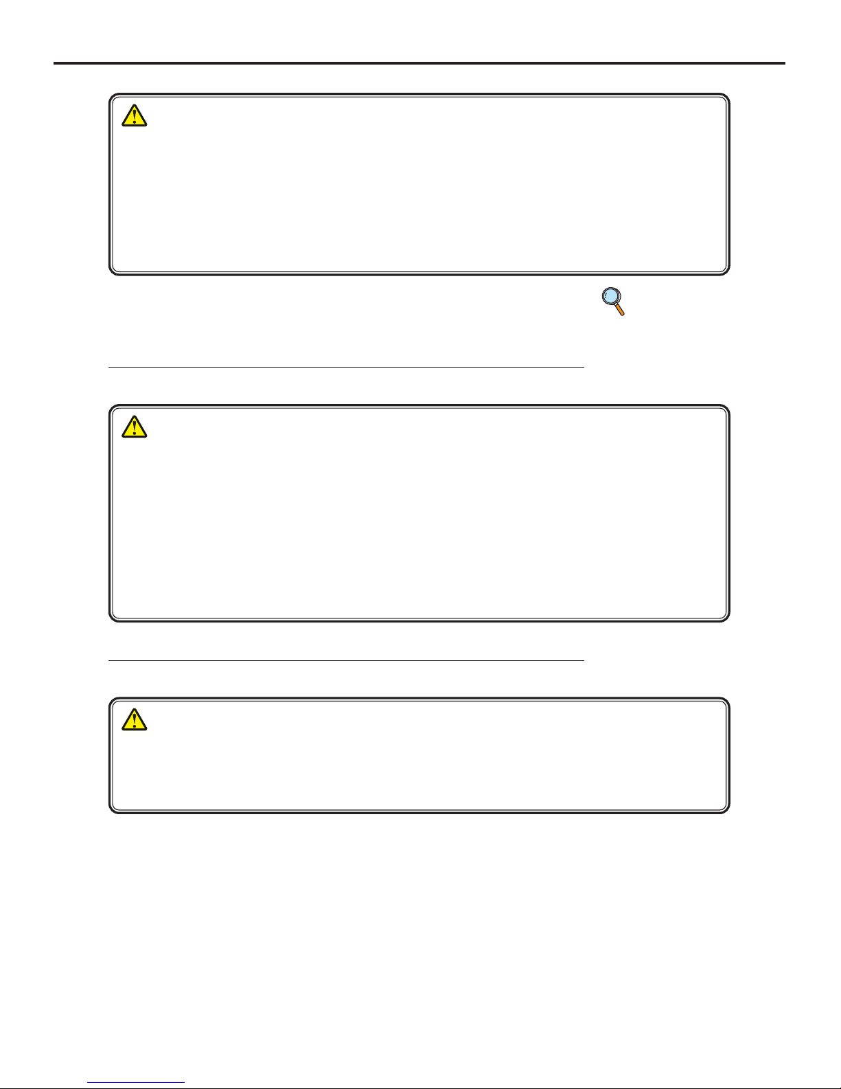
Warning Text (Signal Word)
Signal words indicate the degree of potential hazards in the product.
There are 3 degrees of caution labels, and each is used depending on the level of risk and damage caused by
incorrect use and mishandling.
DANGER
: Failure to observe the caution will produce high risk of serious or fatal injury.
WARNING
: Failure to observe the caution will produce moderate risk of serious or fatal injury.
CAUTION
: Failure to observe the caution will produce risk of moderate or light injury.
Risk of the damage
Bodily injury
(and damage to property)
Damage to property only
Loss of life or serious injury
(Damage is serious)
High Low
DANGER WARNING
WARNING
CAUTION
CAUTION
CAUTION
Moderate damage or light injury
(Damage is light)
or
NOTE : If the contents of this page are not legible, order a new manual.
Ch.1 Safety Precautions & Warnings
< 9 >
DRYPRO Vstage MODEL 793 Operation Manual Ver.1.01 2005.1
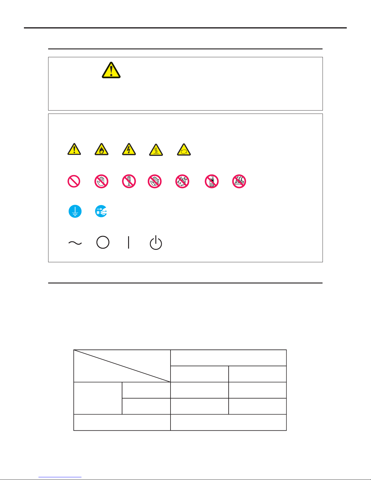
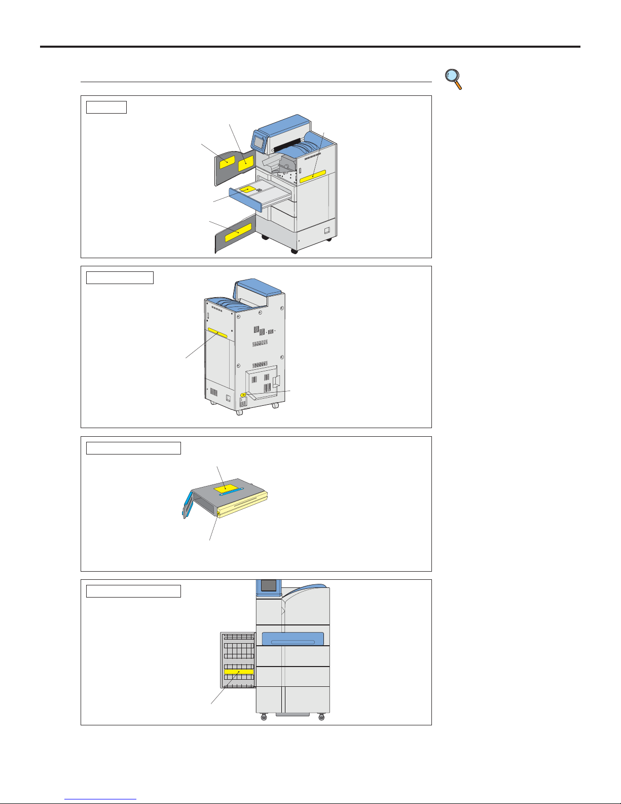
Warning Labels
Warning labels on the DRYPRO 793 are affixed at the locations shown below, and indicate the possible dan-
ger to the user.
NOTE : If the contents of this page are not legible, order a new manual.
(1) Laser Caution Label
(2) High Temp. 100
: Label-1
(4) Class1 Laser Product Label
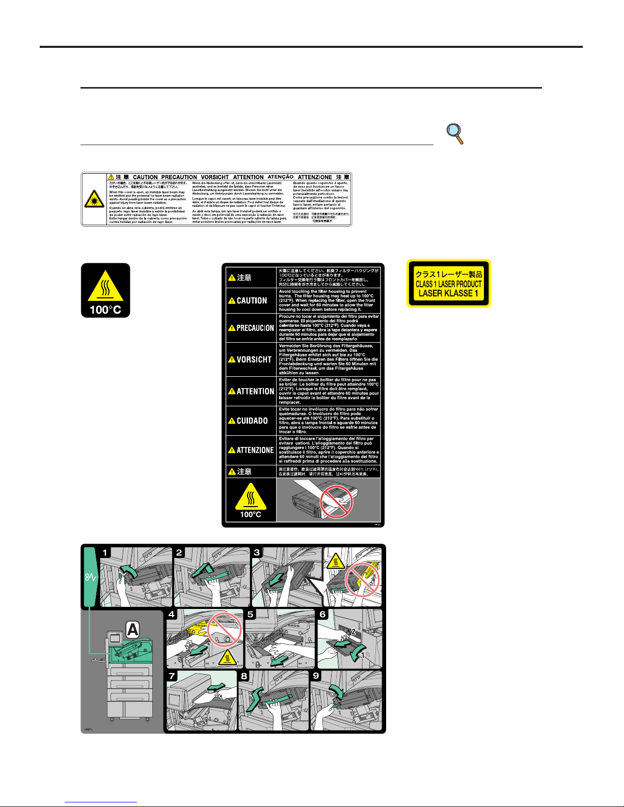
(5) Jam Release Label-A
Description of Warning Labels
p.12 Locations of
Warning
Labels
(3) High Temp. 100: Label-2
Ch.1 Safety Precautions & Warnings
< 10 >
DRYPRO Vstage MODEL 793 Operation Manual Ver.1.01 2005.1
(7) Film Loading Label
(8) Deodorant Filter Change Label
NOTE : If the contents of this page are not legible, order a new manual.
(6) Jam Release Label-B•C
Ch.1 Safety Precautions & Warnings
< 11 >
DRYPRO Vstage MODEL 793 Operation Manual Ver.1.01 2005.1
(9) Cleaning Roller Cleaning Label
NOTE : If the contents of this page are not legible, order a new manual.
Ch.1 Safety Precautions & Warnings
< 12 >
DRYPRO Vstage MODEL 793 Operation Manual Ver.1.01 2005.1
Locations of Warning Labels
NOTE : If the contents of this page are not legible, order a new manual.
p.9 Description
of Warning
Labels
(6) Jam Release Label B¥C
(5) Jam Release Label
(8) Deodorant Filter Change Label
(1) Laser Caution Label
(7) Film Loading Label
(1) Laser Caution Label
(4) Class1 Laser Product Label
Internal
Rear • Left Side
(9) Cleaning Roller Cleaning Label
Cleaning Roller
(3) Deodorant Filter Housing High Temp. 100: Label
(2) High Temp. 100: Label
Deodorant Filter Case
Ch.1 Safety Precautions & Warnings
< 13 >
DRYPRO Vstage MODEL 793 Operation Manual Ver.1.01 2005.1
NOTE : If the contents of this page are not legible, order a new manual.
Cautions for Safety
Thoroughly read the Cautions for Safety before use, and use the device correctly. Strictly observe all cau-
tions detailed here because they are quite important to secure the safe use of the device.
Cautions for Installation
• Never attempt to modify the device.
If you modify the device, this may cause a breakdown, electric shock, or fire.
• For installation, contact a sales office where you purchased this device or your Technical
Representative.
If you install the device and there are any problems in installation, this may cause an electric
shock or a fire.
• Be sure to ground the device well.
Never connect the grounding cable to the gas pipe, water supply pipe, lighting rod, or the grounding cable for telephone.
• As for the electrical work (including grounding and communications cable work) follow the
local regulations on the technical standards.
If the work is not done properly, this may cause an electric shock or breakdown.
• Use the power supply with sufficient capacities according to the specifications.
If you use any power supply other than the specifications, or the power supply with insufficient
capacities, this may result in heating the electrical components or cause a fire.
WARNING
Cautions for Reinstallation, Storage and Repair
CAUTION
• In the event of detection of smoke, unusual odors or sounds, the power should be switched off
immediately and the power plug disconnected from the power outlet. Then contact your Konica Service Representative. Continued use under such circumstances could result in fire.
Continued use of the device despite of such abnormality may result in damage, electric shock or fire.
• Contact your Technical Representative as to the reaction to the errors other than those listed in this
manual.
If the repair is done by the user with some failure, it may cause electric shock or fire.
• For reinstallation, storage and repair, contact a sales office where you purchased this device or your
Technical Representative.
If the device is relocated, reinstalled by the user with some failure, it may cause electric shock or fire.
Ch.1 Safety Precautions & Warnings
< 14 >
DRYPRO Vstage MODEL 793 Operation Manual Ver.1.01 2005.1
Cautions for Usage
• Never open or close any covers other than the specified in this Operation Manual.
High voltage may be applied on some units in the device. If you touch them accidentally, you may
suffer burns or an electric shock.
• When replacing FILTER or removing film jams in the discharge unit, follow the procedure in
this Operation Manual;
otherwise, a fire may be caused.
• Plug the power cable completely.
If dust is accumulated on the power plug, or the power cable is not plugged properly, this may
cause an electric shock or a fire.
• Be sure to use the power cable supplied with this device. Do not use an extension cord or
do not connect another device to the same wall outlet;
otherwise, a fire or heating may be caused.
• Be careful not to trip over the power cable to damage it.
If you continue using the damaged power cable, this may cause an electric shock or fire.
• Do not block the air inlet or the air outlet of this device;
otherwise, a breakdown may be caused.
• Do not start up or shut off the device by plugging or unplugging the power cable;
otherwise, an electric shock or breakdown may be caused.
• If it is likely that lightning may occur, stop operating the device, and unplug the power
cable.
A breakdown may occur depending on the degree of lightning.
• Do not use this device for any purpose other than printing image data;
otherwise, a breakdown may be caused.
• Do not operate the switches with wet hands;
otherwise, you may suffer an electric shock.
• When unplugging the power cable, do not pull it;
otherwise, the inner cable may be broken, and this may cause heating or a fire.
• Do not let this device exposed to water by cleaning the device with a wet cloth or placing
the vase containing water on the device, etc;
otherwise, you may suffer an electric shock due to a leakage of currents.
• Before you clean the device, be sure to stop operating it, and unplug the power cable or turn
the breaker OFF;
otherwise, you may suffer injury or the device may be broken down as the fan rotates at the high
speed in the device.
• If the device is not going to be used for an extended period of time, unplug the power cable
for safety purpose;
otherwise, dust may be accumulated, resulting in heating or a fire.
• When the failure occurs on the device, contact your Technical Representative.
NEVER use the troubled device as it is dangerous.
Note that a laser tube is incorporated in this device, and direct exposure of eye or skin to the laser
beam may result in injury. Also the device contains an assembly using a high voltage. Due case
should be taken not to suffer from electrocution by touching this assembly.
WARNING
NOTE : If the contents of this page are not legible, order a new manual.
Ch.1 Safety Precautions & Warnings
< 15 >
DRYPRO Vstage MODEL 793 Operation Manual Ver.1.01 2005.1
CAUTION
• As for any servicing other than "Servicing by User" described in this Operation Manual, contact a service person as they require an expert technology.
If you perform any service other than "Servicing by User" by yourself, and there are any problems on it, this may
cause an electric shock or fire.
• If the smell is unpleasant, install a ventilating fan in a room where this device is installed.
(Please determine the size and capacity of the fan according to the structure of a room.)
Although a chemical substance is discharged during operation, the amount of emissions is within acceptable limits.
NOTE : If the contents of this page are not legible, order a new manual.
Cautions for Installation Location
CAUTION
Be sure to observe the following conditions for the installation location of this device.
By installing this device in the Radiology Department, you could make the work flow smooth.
1)Install the device in a location where it is not exposed to water.
2)Install the device in a location where it is not exceed the temperatures or atmospheric pressure described in
the specifications.
3)Install the device in a location where it is not exposed to direct sunlight.
4)Install the device in a flat place.
5)Install the device where there is no likelihood of being given by vibration or impact.
6)Install the device in a location where there is no likelihood of being adversely affected by chemical agents,
or air containing gas, dust, salt or sulfur, etc.
7)Install the device where the air inlet or exhaust outlet is not blocked.
Cautions for Disposal
CAUTION
When disposing of the DRYPRO 793 main unit [ including lithium button battery (free from lead, hexavalent
chromium, cadmium, mercury, PBB, PBDE), fluorescent tubes (contained in the LCD module) ], accessories,
options, and films, accept the regulations of each local government.
p.00
Maintenance Proce-
dures to be Carried
out by the Customer

Ch.1 Safety Precautions & Warnings
< 16 >
DRYPRO Vstage MODEL 793 Operation Manual Ver.1.01 2005.1

< 17 >
DRYPRO Vstage MODEL 793 Operation Manual Ver.1.01 2005.1
Product Outline
2
Chap.
Product outline of the DRYPRO 793 is detailed in
this chapter.
Ch.2 Product Outline
< 18 >
DRYPRO Vstage MODEL 793 Operation Manual Ver.1.01 2005.1
2-1 Name of Each Component
Each component and its function of the DRYPRO 793 is detailed below.
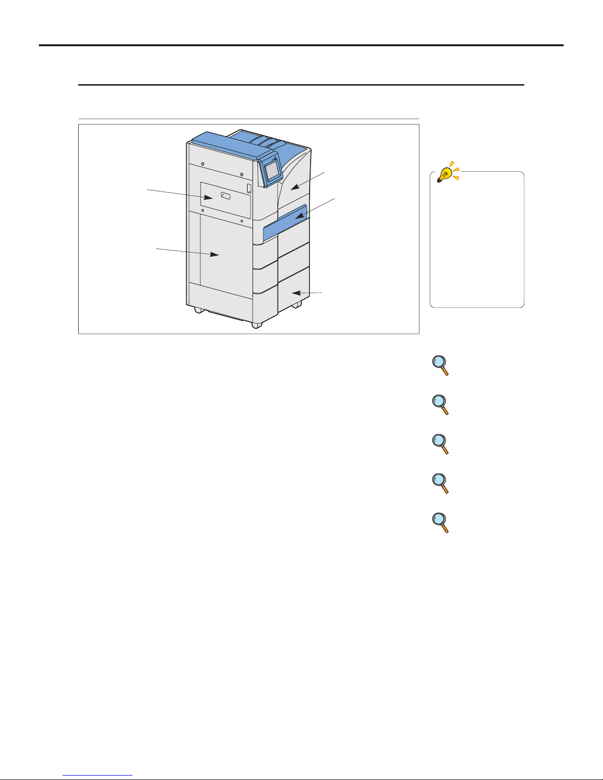
2-1-1 Front and Left Side View
Film size for the
DRYPRO 793 can be
selected from 14"x17",
14"x14", 11"x14",
10"x12", 8"x10". Set up
of the film size selected
by the facility will be
made by the service
representative at the
time of installation of the
DRYPRO 793.
1) Front Upper Cover
3) Front Lower Cover
2) Supply Tray 1
1) Front Upper Cover
When a film jam occurs in HPRO(Hear Processing Unit) - Cooling Unit, open this
cover and take the jammed film out. Also
open when the deodorant filter is replaced.
2) Supply1
(Standard : 1 trays, with option : max. 3 trays)
Load films in these trays.
3) Front Lower Cover
When a film jam occurs in Descent or Elevator transport unit, or Film Justification
unit, open this cover and take the jammed
film out. Also it is possible to send the
jammed film to the left cover or right cover
accessing through this opening.
4) Exit Cover
When a film jam occurs in Ejection Unit,
open this cover and take the jammed film
out.
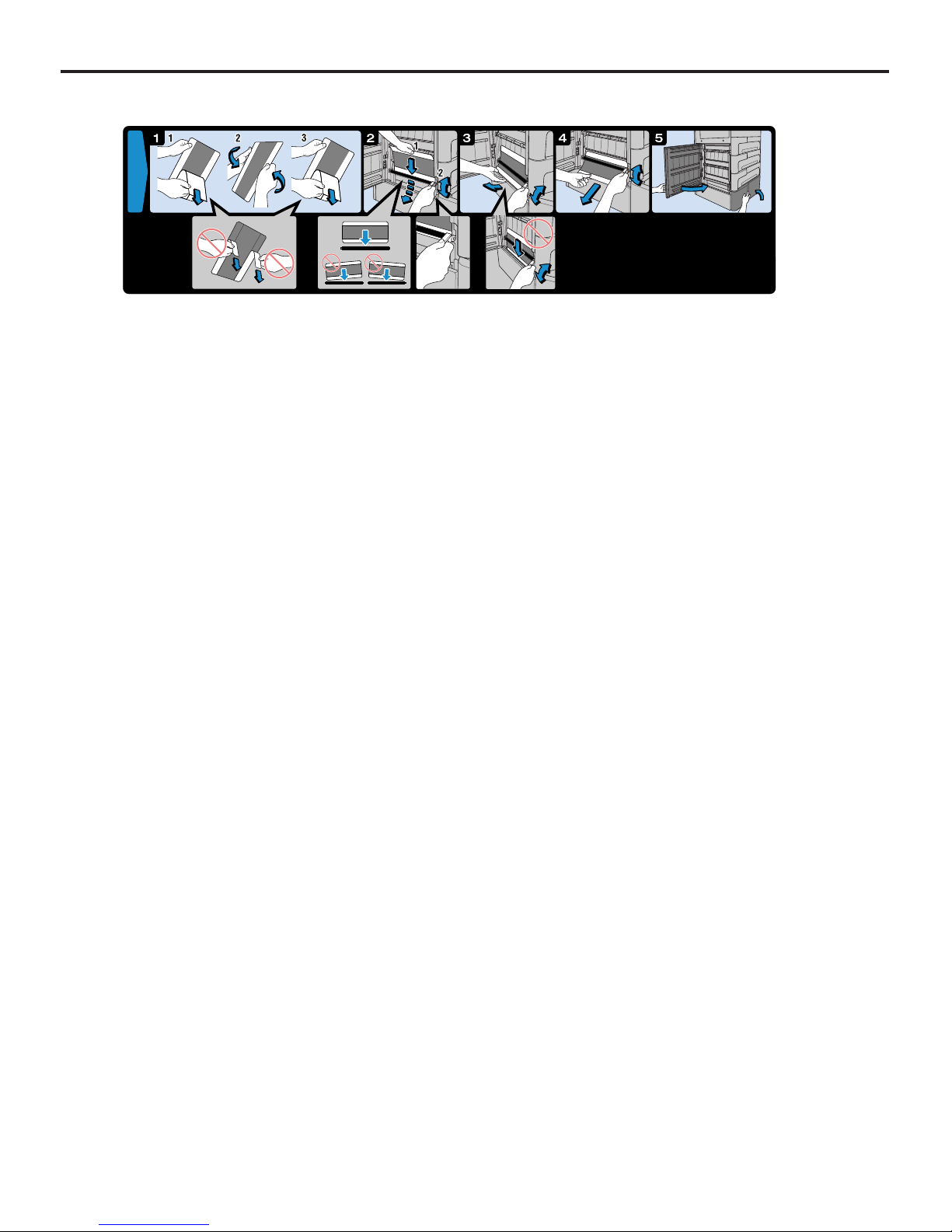
5) Left Cover
When a film jam occurs in Descent Transport unit, open this cover and take the
jammed film out. Also open when cleaning
of the cleaning roller is performed.
p.19 Operation
Panel
p.93 Front Cover
Open
p.24 Supply Tray
& Cutter
4) Exit Cover
5) Left Cover
p.132 Film Jam in
the Descent
Transport Unit
p.95 Dust
Cleaning
Ch.2 Product Outline
< 19 >
DRYPRO Vstage MODEL 793 Operation Manual Ver.1.01 2005.1
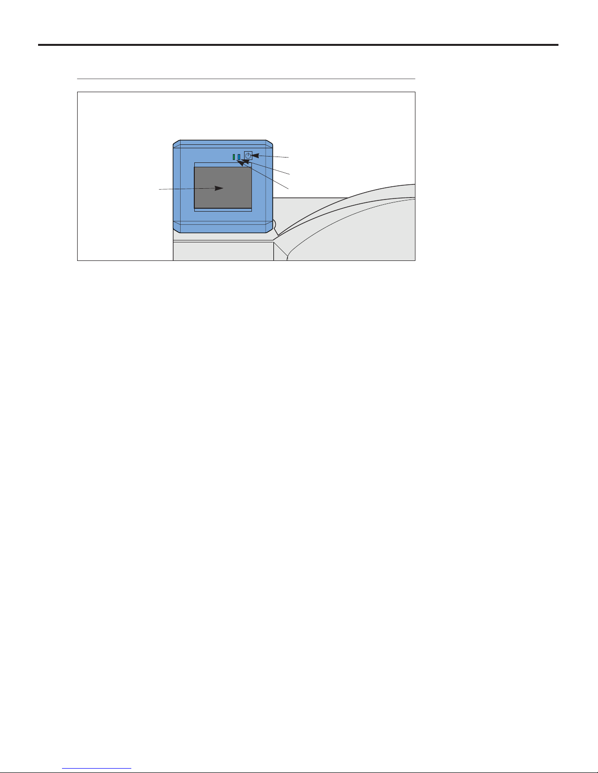
1) Operation Button
Start up or shut down the DRYPRO
793.
2) Operation Lamp(blue/orange)
Operating : Lights in blue
Start Timer ON : Lights in blue
Shutdown Process : Blinks in blue
Power OFF
(Breaker ON) : Lights in orange
Power OFF
(Breaker OFF): Extinguished
3) Timer Lamp
(green)
Lights when the Start Timer is ON.
4) Operation Panel
Operates and performs various settings
for the DRYPRO 793. Also displays various messages.
2-1-2 Operation Panel
1) Operation Button
2) Operation Lamp
3) Timer Lamp
4) Operation Panel
Ch.2 Product Outline
< 20 >
DRYPRO Vstage MODEL 793 Operation Manual Ver.1.01 2005.1
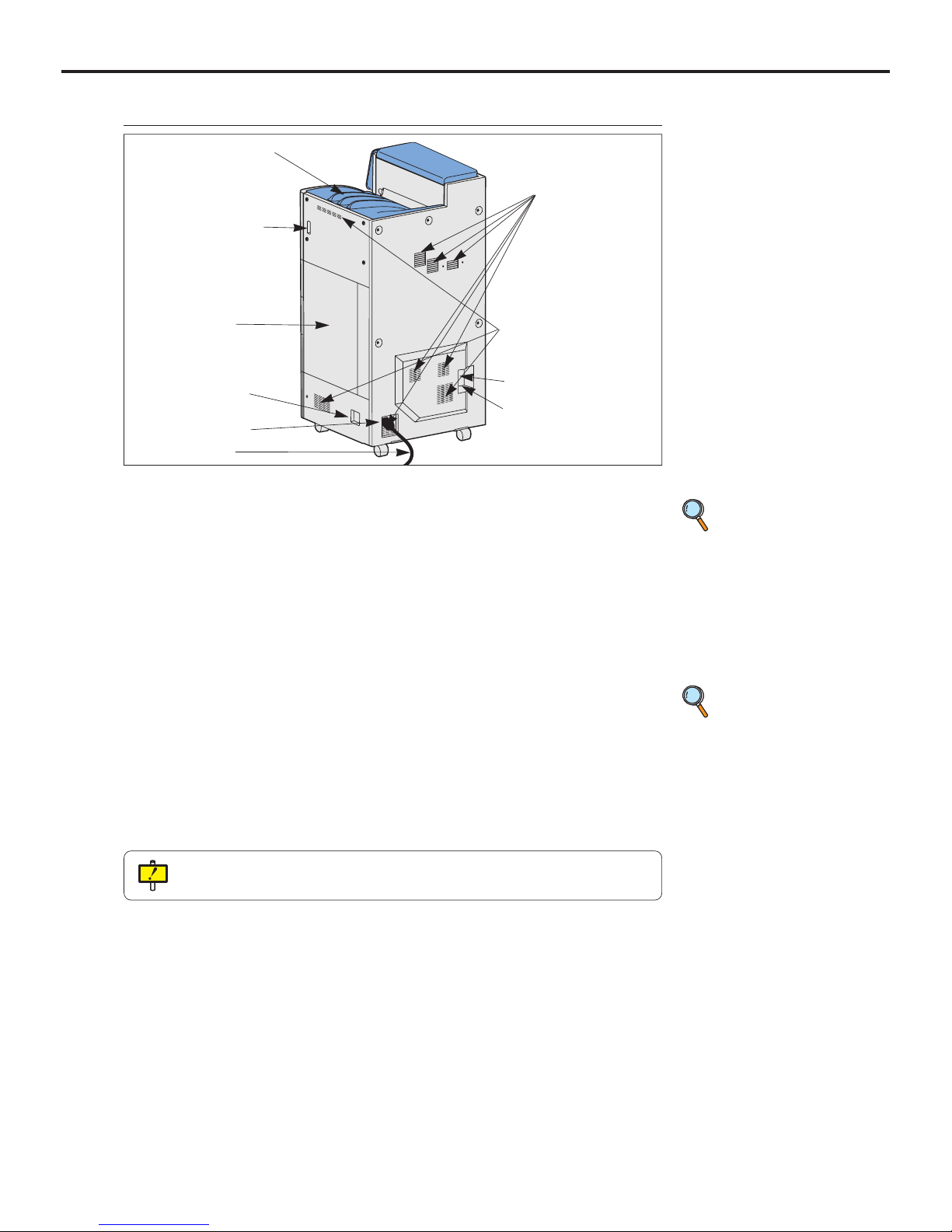
6) Power Cable
7) Outlet
9) Ethernet Port
5) Power Cable
Connector
1) Film Exit Tray
Printed films are output to this tray.
When an optional "6ch Sorter" is
installed, films are output to the sorter.
2) Front Upper Cover Release Lever
Releases the lock of the Front Upper
Cover when it is necessary to open.
3) Right Cover
When a film jam occurs in the Elevator
Transport unit, open this cover and take
the jammed film out.
4) Power Breaker
Turns ON/OFF the main power.
5) Power Cable Connector
Plug in the Power Cable.
6) Power Cable
Connects the DRYPRO793 to the
power outlet of the facility.
7) Outlet (6 locations)
Air used to cool inside of the unit is
exhausted from this slot.
8) Inlet (2 on the right side, 1 on the rear
side)
Takes in the air to cool inside of the
unit.
9) Ethernet Port
Connects to the network.
10) Serial Port
When a backup battery is used, connect
the cable of the backup battery to this
port.
2-1-3 Rear, Right Side, Top View
10) Serial Port
8) Inlet
p.139 Film
Jam in the Sorter
Transport Unit
4) Power Breaker
3) Right Cover
2) Front Upper Cover
Release Lever
p.136 Film
Jam in the Elevator
Transport Unit
1) Film Exit Tray
Do not leave films equivalent to one package (= 125 sheets) or more on the Film Exit
Tray.
Ch.2 Product Outline
< 21 >
DRYPRO Vstage MODEL 793 Operation Manual Ver.1.01 2005.1
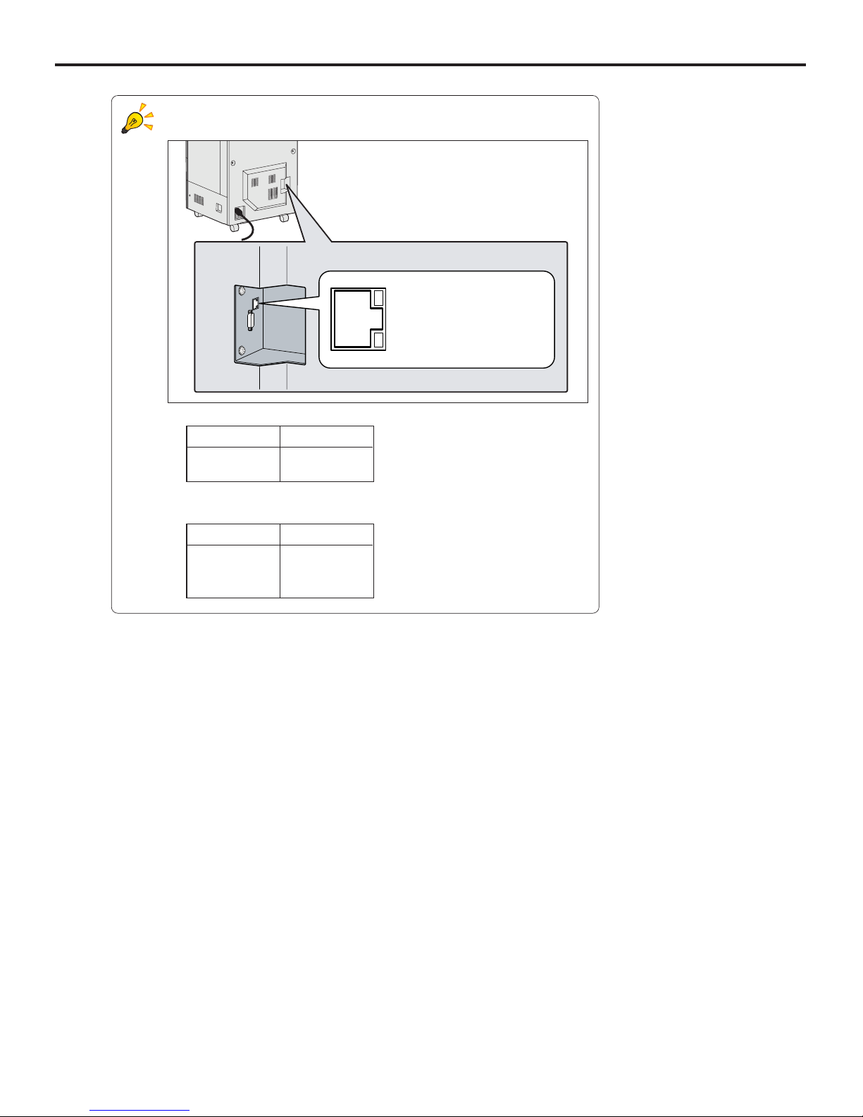
LEDs at the Ethernet Port.
Two LEDs at the Ethernet Port indicate the following.
- Link/Activity LED (upper)
- Com. Speed LED (lower)
Com. Speed LED
10Mbps Extinguished
100Mbps Lights in orange
1000Mbps Lights in green
Com. Status LED
Link Lights in orange
Activity Lights in green
Link / Activity LED
Com. Speed LED
Lower right of the rear
Ch.2 Product Outline
< 22 >
DRYPRO Vstage MODEL 793 Operation Manual Ver.1.01 2005.1
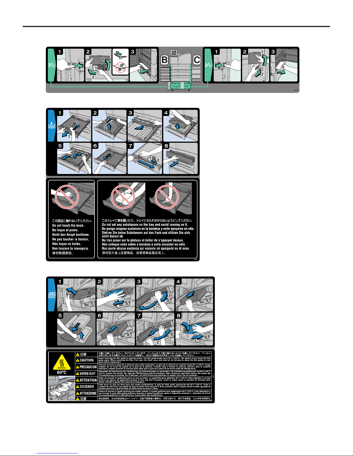
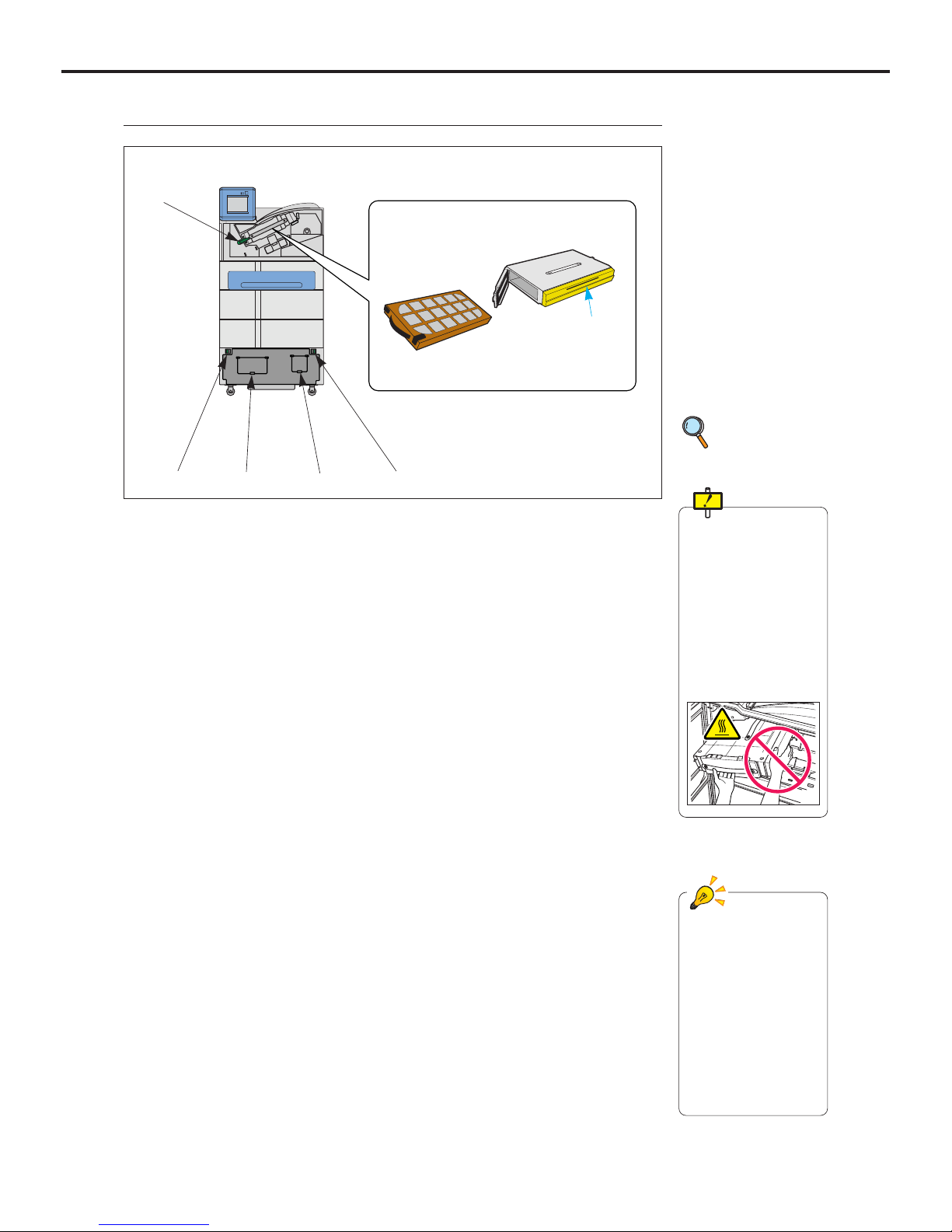
2-1-4 Main Unit without Outer Covers
p.128 Resolving
the Film Jam
Be careful not to touch
the Deodorant filter
Housing (yellow) when
pulling out the Deodor-
ant Filter Case.
Deodorant Filter Hous-
ing is heated above
100:, and touching it
may cause burn.
1) Lever-A (green)
Locks the Deodorant Filter Case.
2) Lever-B (green)
Unlock this lever when opening the Left
Cover.
3) Lever-C (green)
Unlock this lever when opening the
Right Cover.
4) Cover-B
When a film jam occurs in the path
between the Descent Transport unit and
the Justification unit, open this cover to
send the jammed film to the Descent
Transport unit.
5) Cover-C
When a film jam occurs in the path
between the Justification unit and the
Elevator Transport unit , open this cover
to send the jammed film to the Elevator
Transport unit.
6) Deodorant Filter
Removes the odor that is generated
during Heat Processing. It is necessary
to regularly change the Deodorant Filter.
7) Deodorant Filter Case
Contains the Deodorant Filter. To
change the Deodorant Filter, open the
cover for the Deodorant Filter Case.
When a film jam occurs in the HPRO ~
Film Discharge unit, remove the
Deodorant Filter Case to take the
jammed film out.
7) Deodorant Filter Case
6) Deodorant Filter
1) Lever-A
Housing (yellow)
2) Lever-B 3) Lever-C
4) Cover-B 5) Cover-C
Levers and knobs in the
DRYPRO 793 are
painted in different col-
ors depending on the
purpose of use.
Blue : For mainte-
nance and
inspection
Green : For removal of
jam films.
Ch.2 Product Outline
< 23 >
DRYPRO Vstage MODEL 793 Operation Manual Ver.1.01 2005.1
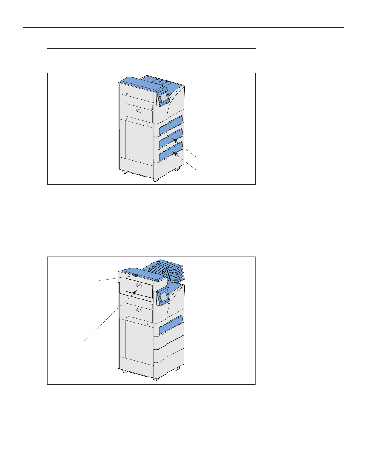
1) Supply 2, 3 Tray
(2nd, 3rd tray)
Load the film.
2-1-5 Options
1) Supply 3 Tray
1. Supply 2, 3 Tray
1) Lis-793
Printed films are output to five bins of
the sorter and to the Film Exit Tray
depending on the setup.
2) Sorter Cover
When a film jam occurs in the Sorter
Transport unit, open this cover to
remove the jammed film.
1) Lis-793
2) Sorter Cover
2. Lis-793
1) Supply 2 Tray
Ch.2 Product Outline
< 24 >
DRYPRO Vstage MODEL 793 Operation Manual Ver.1.01 2005.1
1) Shutter
2) Holding Plate
3) Winding Shaft
4) Cutter Pocket
5) Cutter
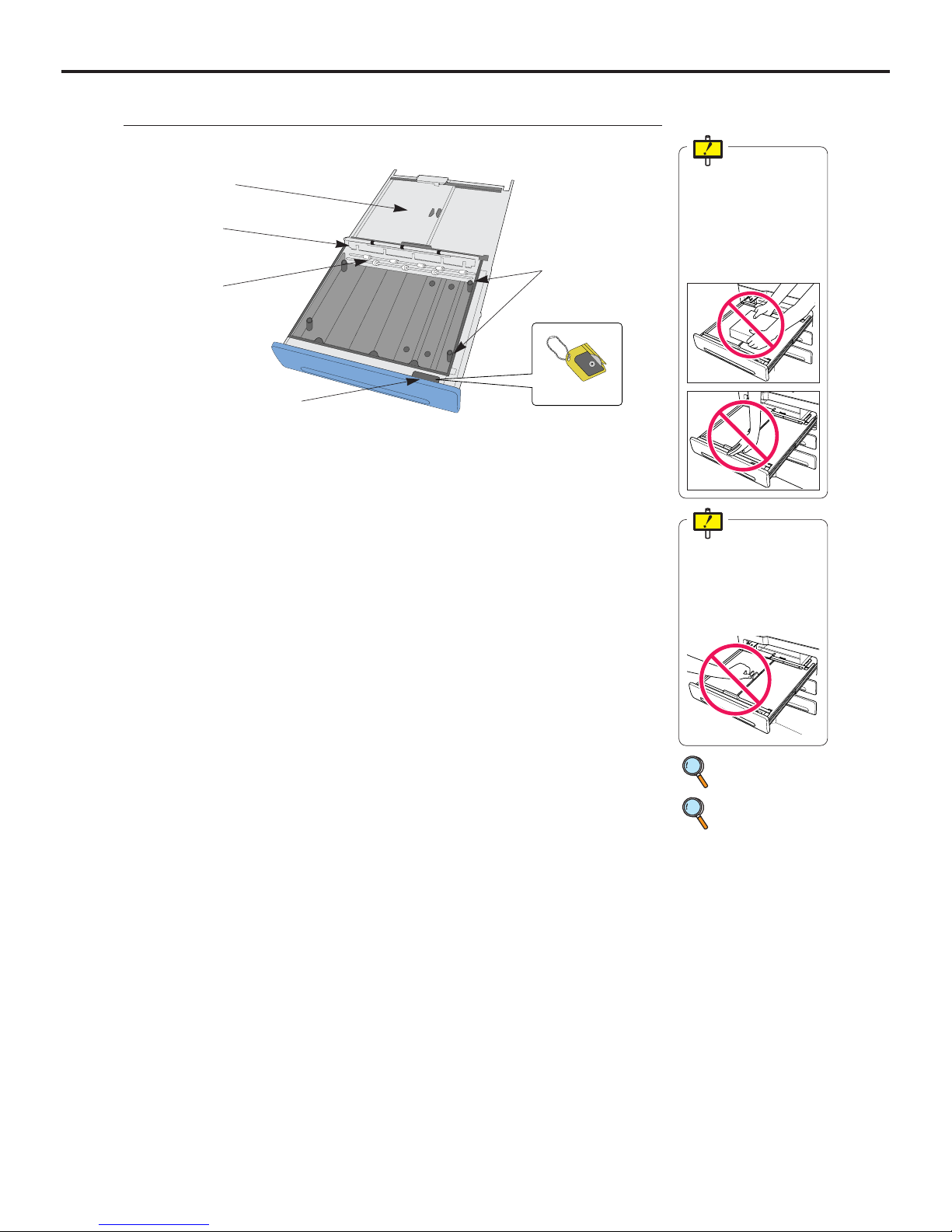
2-1-6 Supply Tray & Cutter
1) Shutter
Protect the film from being exposed to
the external light.
2) Holding Plate
Press and hold the edge of the film
package when loading the film.
3) Winding Shaft
Wind the film package when it is loaded.
Next time when a new film package is
loaded, unwind and remove the previous film package before the new film
package is loaded.
4) Cutter Pocket
Holds the cutter.
5) Cutter
Use this cutter to cut the film package
when it is newly loaded.
6) Side Stopper
Replace the position of Side Stoppers
when the film size is changed.
p.35 Film Loading
Do not place anything
or lean on the Supply
Tray when it is pulled
out from the DRYPRO
793. It may cause damage to the device.
Do not touch the shutter knob, otherwise it
may cause an accidental exposure of the film.
p.42 Changing the
Film Size and
Film Type
6) Side Stoppers
Ch.2 Product Outline
< 25 >
DRYPRO Vstage MODEL 793 Operation Manual Ver.1.01 2005.1
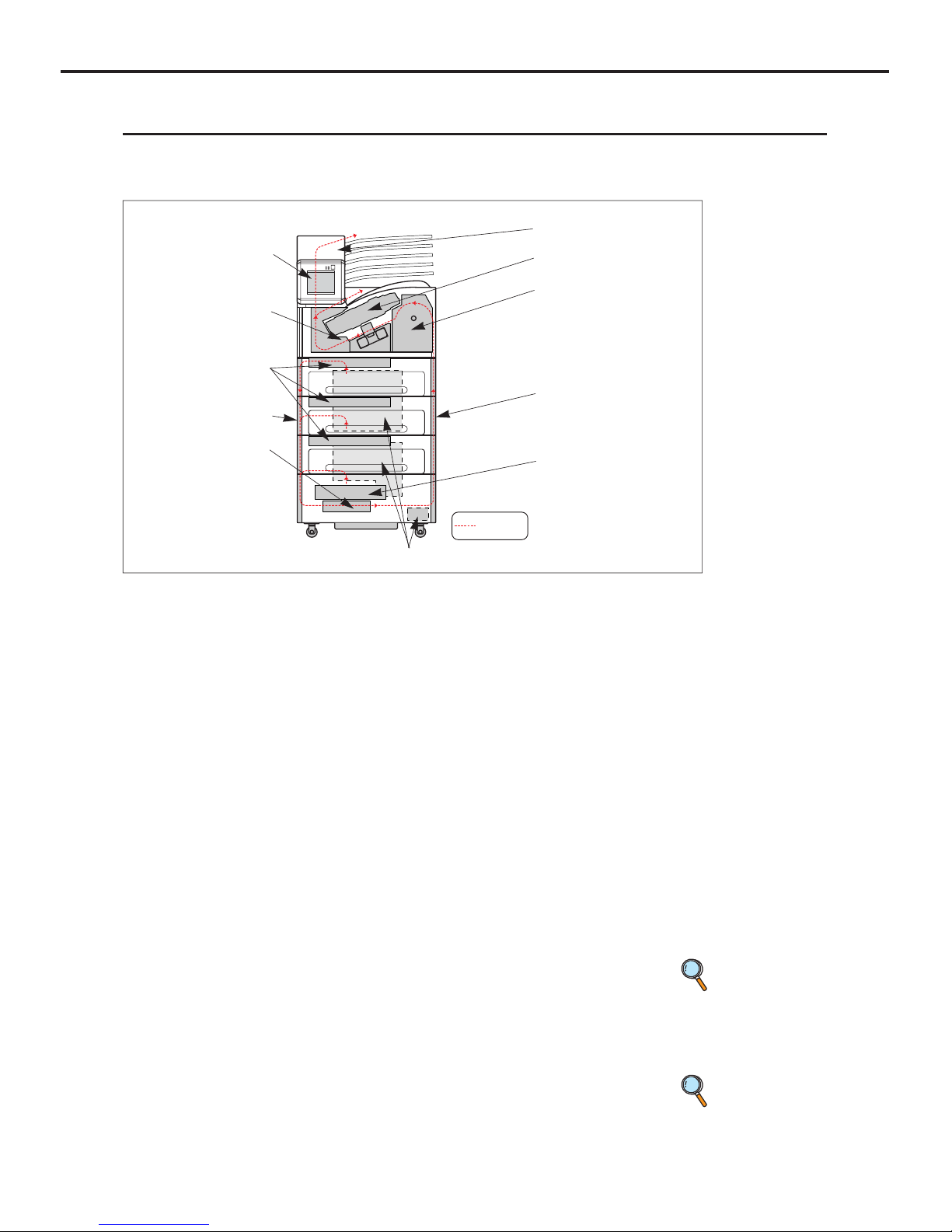
2-2 Internal Structure
Internal structure of the DRYPRO 793 is outlined below.
A film is transported from 1) through 7) in sequence in print process.
1) Supply Unit (available to each Supply Tray)
Picks up films in the Supply Tray unit one by one, and sends it to the Descent Transport unit.
2) Descent Transport Unit
Sends a film picked up at the Supply unit to the Justification unit.
3) Justification Unit
Aligns the right and left edge of the film sent from the Descent Transport unit, and
sends to the Exposure unit.
4) Exposure Unit (a: Sub-Scan Unit, b: Main Scan Unit)
Performs a laser scanning in synchronization with the film transport and prints an
image on the film.
5) Elevator Transport Unit
Sends the film to the HPRO (Heat Processing) unit after the exposure.
6) HPRO Unit
Processes the exposed film by heating.
7) Cooling/Discharge Unit
Cools the heat-processed film and discharges it.
8) Deodorant Filter
Removes the odor generated in heat processing. It is necessary to regularly change
the Deodorant Filter.
9) Electrical Components Unit
Consists of the power supply unit for supplying the power to the device and the control
unit for controlling the entire device, communicating with the diagnostic devices, and
processing / controlling images.
10) Operation Panel
Operates and makes settings of the DRYPRO 793.
11) Lis-793 (option)
Discharges the film discharged from the main body into the specified bin.
Film Pass
1) Supply Unit
2) Descent Transport
Unit
4) Exposure Unit
5) Elevator Transport
6) H-PRO Unit
7) Cooling/Discharge
Unit
8) Deodorant Filter
9) Electrical Unit (rear)
10) Operation Panel
p.19 Operation
Panel
p.142
Replacement
of Deodorant
Filter
3) Justification Unit
11) Lis-793

Ch.2 Product Outline
< 26 >
DRYPRO Vstage MODEL 793 Operation Manual Ver.1.01 2005.1

< 27 >
DRYPRO Vstage MODEL 793 Operation Manual Ver.1.01 2005.1
Operation
3
Chap.
How to operate the DRYPRO 793 is detailed in
this chapter.
Ch.3 Operation
< 28 >
DRYPRO Vstage MODEL 793 Operation Manual Ver.1.01 2005.1
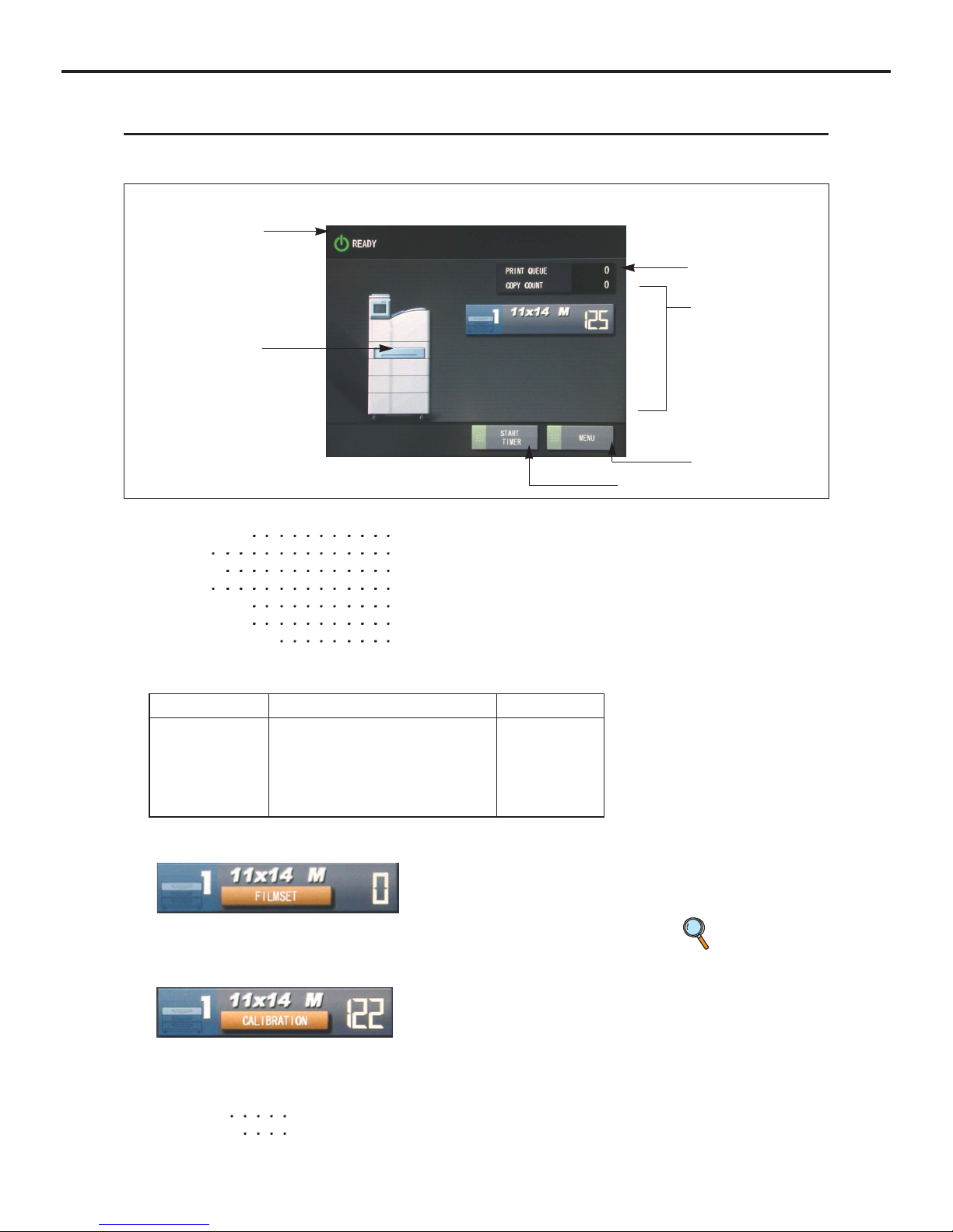
3-1 Operation Panel
The operation, control and settings of this device can be made by using the control panel located on the main unit.
The following shows the operating procedures.
1) Message Column
3) Job Info.
2) Loaded Film Info.
4) Status Info.
6) [Menu] Button
5) [Start Timer] Button
1) Message Column : Displays the status of the DRYPRO 793.
Warming Up
Warming up
Ready
Ready for print
Printing
In printing process
Error
Error occurred
Error Reset
Error in reset process
Maintenance
Servicing in Maintenance Mode
Web User Busy
Accessed by Web user
2) Displays film type, size, number of remaining films in the Tray 1, 2, 3.
Display changes as follows when the film is empty.
Touching the area where "Film Set" is displayed initiates the film loading sequence.
Display changes as follows when the density calibration is required.
(Note : depending on the calibration settings)
Touching the area where "Calibration" is displayed initiates the automatic density
calibration.
3) Job Info. : Copy Count at present waiting for printout.
Queues
The number of jobs waiting for printout.
Print Count
Count of jobs in printing and unprinted.
p.35 FILM
LOADING
Size Film Type Remaining
14x17 B (blue) SD-P) 0-126
14x14 C (clear) (SD-PC)
11x14 M (mammo) (SD-PM)
10x12
8x10
 Loading...