

Komatsu PC210, PC210LC-6K, PC240LC, PC240NLC-6K Service Manual

EEAM006011
Operation &
Maintenance Manual
PC210, PC210LC
PC240LC,PC240NLC-
HYDRAULIC EXCAVATOR
SERIAL NUMBER
PC210-6K - K34552
PC210LC-6K - K34552
PC240LC-6K - K34227
PC240NLC-6K - K34227
and up
and up
and up
and up
-
6K
6K
WARNING
Unsafe use of this machine may cause serious injury or
death. Operators and maintenance personnel must read
this manual before operating or maintaining this
machine. This manual should be kept inside the cab for
reference and periodically reviewed by all personel who
will come into contact with the machine.


FOREWORD
FOREWORD
This manual provides rules and guidelines which will help you use this machine safely and effectively. Keep this
manual handy and have all personnel read it periodically. If this manual has been lost or has become dirty and can
not be read, request a replacement manual from Komatsu or your Komatsu distributor.
If you sell the machine, be sure to give this manual to the new owners.
Continuing improvements in the design of this machine can lead to changes in detail which may not be reflected in
this manual. Consul t Komatsu or your Komatsu distr ibutor for th e latest avai lable inf ormatio n for your machi ne or
for questions regarding information in this manual.
WARNING
● This operation & maintenance manual may contain
attachments and optional equipment that are not available in your area. Please consult you r loca l Komatsu distributor for those items you require.
● This machine complies with EC directive (89/392/EEC).
Machines complying with this directive display the CE
mark
● Improper operation and maintenance of this machine can
be hazardous and could result in serious injury or death.
● Operators and maintenance personnel should read this
manual thoroughly before beginning operation or maintenance.
● Some actions involved in operation and maintenance of
the machine can cause a seri ous accid e nt, if the y are not
done in a manner described in this manual.
● The procedures and precautions given in this manual
apply only to intended uses of the machine. If you use
your machine for any unintended uses that are n ot specifically prohibited, you must be sure that it is safe for
you and others. In no event should you or others engage
in prohibited uses or actions as described in this manual.
● Komatsu delivers machines that comply with all applica-
ble regulations and standards of the country to which it
has been shipped. If this machine has been purchased in
another country or purchased from someone in another
country, it may lack certain safety devices and specifications that are necessary for use in your country. If there
is any question about whe ther your product compli es
with the applicable standards and regulations of your
country, consult Komatsu or your Komatsu distributor
before operating the machine.
● The description of safety is given in see “SAFETY
INFORMATION” on page 2. and in "SAFETY" from
page 17.
1

SAFETY INFORMATION
SAFETY INFORMATION
SAFETY MESSAGES
Most accidents are caused by the failure to follow fundamental
safety rules for the operation and maintenance of machines.
To avoid accidents, read, understand and follow all precautions
and warnings in this manual an d on the machin e before perf orming operation and maintenance.
To ide ntify h azar ds on the m achin e picto rial dec als ar e used (see
“POSITION FOR ATTACHING SAFETY LABELS” on page 49).
RED WARNING TRIANGLE - This is used on safety labels
where there is a high prob ability o f serious injury or deat h if the
hazard is not avoided. These safety messages or l abels usually
describe precautions that must be taken to avoid the hazard. Failure to avoid this h azard m ay al so r esult in s erious damage to the
machine.
ORANGE WARNING TRIANGLE - This is used on safety
labels where there is a po tentially dangerous s ituation which
could result in se ri ou s i nj ury o r deat h i f the haz ar d is not av oid ed.
These safety messages or labels usually desc ribe precautions
that must be taken to avoid the haza rd. Fail ure to av oid this h azard may also result in serious damage of the machine
YELLOW SAFETY TRIANGLE - This is used on safety
labels for hazards which could result in minor or moderate injury if
the hazard is not avoided. This word might also be used for a hazard where the only result could be damage to the machine.
NOTICE
This word is used for precau tions that must be taken to
avoid actions which could shorten the life of the machine.
Safety precautions are described in "SAFETY" from page 17.
Komatsu cannot predict every circumstance that might involve a
potential hazard in operation and maintenance. Therefore the
safety message in this manual and on the machine may not
include all possible safety precautions. If any procedures or
actions not speci fically rec ommended or allowed in this manual
are used, you m us t be s ur e tha t y ou a nd ot her s can do such pro cedures and actions sa fely a nd without dam aging the mac hine. If
you are unsure about the safety of some procedures, contact
Komatsu or your Komatsu distributor.
2

NOISE PC210, PC210LC-6K
Valid until 31 December 2001
● Operator ears noise value (Sound pressure level)
SAFETY INFORMATION
LpA
77
95/27/EC
● Ambient noise value (Sound power level)
Noise level indicated is the guaranteed value as specified in the
directive 86/662/EEC as amended by 95/27/EC
LWA
105
95/27/EC
3

SAFETY INFORMATION
Valid as of 1 January 2002
● Sound pressure level at the operator's station, measured
according to ISO6396 (Dynamic test method, simulated working cycle)
● Sound power leve l emitted. Th is is the guaran teed value as
specified in European directive 2000/14/EC.
4

NOISE PC240LC, PC240NLC-6K
Valid until 31 December 2001
● Operator ears noise value (Sound pressure level)
SAFETY INFORMATION
LpA
77
95/27/EC
● Ambient noise value (Sound power level)
Noise level indicated is the guaranteed value as specified in the
directive 86/662/EEC as amended by 95/27/EC
LWA
105
95/27/EC
5

SAFETY INFORMATION
Valid as of 1 January 2002
● Sound pressure level at the operator's station, measured
according to ISO6396 (Dynamic test method, simulated working cycle)
● Sound power leve l emitted. Th is is the guaran teed value as
specified in European directive 2000/14/EC.
VIBRATION
The weighted root mean square acceleration valu e to which the
operator’s arms are subjected does not exceed 2.5 m/s²
The weighted root mean square acceleration valu e to which the
operator’s body is subjected does not exceed 0.5 m/s²
These results were obtained by accelerometers during trench digging.
6

INTRODUCTION
INTENDED USE
This Komatsu HYDR AUL IC EXCAVATOR is designed t o be used
mainly for the following work:
● Digging
● Smoothing work
● Ditching work
● Loading work
See the section “WORK POSSIBLE USING HYDRAULIC
EXCAVATOR” on page 129 for further details
FEATURES
INTRODUCTION
● This Komatsu HYDRAULIC EXCAVATOR is equipped with
various controls based on an advanced electronics system.
● The monitor panel greatly facilitates daily maintenance and
self-diagnosis.
● Working mode, travel speed and swing priority are selectable.
● Digging and lifting forc e can b e increas ed by ligh t-touch co n-
trol. (For details, see operation section.)
● Adjustable wrist contro l levers make operations sm ooth and
easy.
● Fresh filtered air conditioner assures comfortable operation.
● Low noise level and smart urban style design and colouring.
● Superb operation pe rformance provided by powerful engine
and high-performance hydraulic pumps.
● Low fuel consumption con troll ed by a n electro nic cont rol sys-
tem provides an environment-friendly machine.
7

INTRODUCTION
BREAKING IN YOUR NEW MACHINE
Your Komatsu machi ne ha s b een t horo ughl y ad just ed a nd te sted
before shipment.
However, operating the machine under severe condi tions at the
beginning can adversely affect the performance and shorten the
machine life.
Be sure to break in the machine for the initial 100 hours (as indicated by the hour meter.)
During breaking in:
● Idle the engine for 5 minutes after starting it up.
● Avoid operation with heavy loads or at high speeds.
● Sudden starting or acceleration, unnecessarily abrupt braking
and sharp turning should be avoided except in cases of emergency.
Additionally for the first 20 hours
● Avoid operating engine for prolonged periods at constant
speed (including idle.)
● Avoid high speed travelling for period s of more than 5 min-
utes.
Pay particular attention to oil pressure and temperature indicators
& check coolant and oil levels frequently during breaking in.
The precautions given i n this manu al for operatin g, m aintenanc e,
and safety procedures are only those that apply when this product
is used for the specified purpose. If the machine is used for a purpose that is not list ed in this ma nual, Koma tsu cannot bear an y
responsibility for safety. All consideration of safety in such operations is the responsibility of the user.
Operations that are prohibited in this manual must never be carried out under any circumstances.
8
LOCATION OF PLATES, TABLES TO ENTER SERIAL NO. AND DISTRIBUTOR
LOCATION OF PLATES, TABLES TO ENTER SERIAL NO.
AND DISTRIBUTOR
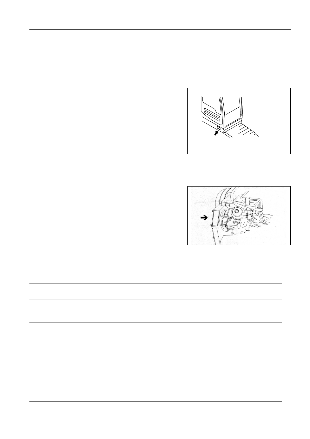
MACHINE SERIAL NO. PLATE POSITION
On the front bottom right of the operator’s cab
ENGINE SERIAL NO. PLATE POSITION
AM088910
On the upper side of the engine cylinder head cover.
TABLE TO ENTER SERIAL NO. AND DISTRIBUTOR
Machine serial No.
Engine serial No.
Manufacturers name: KOMATSU UK Ltd.
Address: Durham Road
Birtley
Chester-Le street
County Durham DH32QX
United Kingdom
Distributor
Address
Phone
9

LOCATION OF PLATES, TABLES TO ENTER SERIAL NO. AND DISTRIBUTOR
MACHINE SERIAL PLATE.
MASS
Komatsu UK Ltd, Birtley, Co. Durham, United Kingdom
205-00-K1290
10

CONTENTS
FOREWORD .................... ................................. ................................ ................................ ...................................... 1
SAFETY INFORMATION ........................................................................................................................................ 2
SAFETY MESSAGES ............................ ...... ....... ...... ....... ...... ....................................... ...... ......................... 2
NOISE PC210, PC210LC-6K ........................................................................................................................ 3
NOISE PC240LC, PC240NLC-6K ................................................................................................................ 5
VIBRATION ................................................................................................................................................... 6
INTRODUCTION ..................................................................................................................................................... 7
INTENDED USE ........................................................................................................................................... 7
FEATURES ......................... .......................... .................... ......................... ................................................... 7
BREAKING IN YOUR NEW MACHINE ........................................................................................................ 8
LOCATION OF PLATES, TABLES TO ENTER SERIAL NO.
AND DISTRIBUTOR ............................................................................................................................................... 9
MACHINE SERIAL NO. PLATE POSITION .................................................................................................. 9
ENGINE SERIAL NO. PLATE POSITION .................................................................................................... 9
TABLE TO ENTER SERIAL NO. AND DISTRIBUTOR ................................................................................ 9
MACHINE SERIAL PLATE. ....................................... ....... ...... ...... ....... ...... ....... ...... .................................... 10
SAFETY.............................................................................................................. 17
GENERAL PRECAUTIONS ... ...... ....... ...... ....... ...... ....... ...... ....... ...... ...... ....................................... ....................... 18
PRECAUTIONS DURING OPERATION .................................... ...... ...... ....... ...... ....... ...... ....... ...... ....... ................ 26
BEFORE STARTING ENGINE ................................................................................................................... 26
OPERATING MACHINE ............................................................................................................................. 28
TRANSPORTATION .................. ................................ ................................ ................................................. 35
BATTERY ................................................................................................................................................... 36
TOWING ..................................................................................................................................................... 37
BUCKET WITH HOOK ................................................................................................................................ 38
PRECAUTIONS FOR MAINTENANCE .................. ....... ...... ....... ...... ...... ....... ...... ....... ...... ....... ...... ....................... 41
BEFORE CARRYING OUT MAINTENANCE ............................................................................................. 41
DURING MAINTENANCE ........................................................................................................................... 44
POSITION FOR ATTACHING SAFETY LABELS ................................................................................................ 49
POSITION FOR ATTACHING SAFETY LABELS ......................... ....... ...... ....... ...... ....... ...... ....... ...... ....... ... 49
OPERATION.......................................................................................................55
GENERAL VIEW .............................................. ...... ....... ...... ....... ...... ...... ....... ...... ....... ...... .................................... 56
GENERAL VIEW OF MACHINE ................................................................ ....... ...... ....... ...... ....... ................ 56
GENERAL VIEW OF CONTROLS AND GAUGES ..................................................................................... 57
11

EXPLANATION OF COMPONENTS .................................................................................................................... 59
MACHINE MONITOR ................................................................................................................................. 59
METERS ..................................................................................................................................................... 65
SWITCHES ................................................................. ................................................................................ 70
CONTROL LEVERS, PEDALS ................................................................................................................... 76
AIR CONDITIONER .................................................................................................................................... 87
CAB RADIO ................................................................................................................................................ 90
FUSE .......................................................................................................................................................... 91
FUSIBLE LINK ............................................................................................................................................ 92
CONTROLLERS ......................................................................................................................................... 92
TOOL BOX .................................................................................................................................................. 92
REFUELLING PUMP .................................................................................................................................. 93
HANDLING THE ACCUMULATOR ..................... ....................................... ...... ....... ...... ....... ...... ....... ......... 94
OPERATION ........................... .................................................... .......................................................................... 95
CHECK BEFORE STARTING ENGINE ...................................................................................................... 95
STARTING ENGINE ................................................................................................................................. 106
OPERATIONS AND CHECKS AFTER STARTING ENGINE ................................................................... 108
MOVING MACHINE OFF .......................................................................................................................... 114
STEERING MACHINE .............................................................................................................................. 117
STOPPING MACHINE .............................................................................................................................. 119
SWINGING ............................................................................................................................................... 120
OPERATION OF WORK EQUIPMENT ....................................................................................................121
HANDLING ACTIVE MODE . ...... ....... ...... ....... ...................................... ....... ...... ....... ...... ....... ...... .............. 122
WORKING MODE SELECTION ............................................................................................................... 123
PROHIBITIONS FOR OPERATION ......................................................................................................... 125
PRECAUTIONS FOR OPERATION ......................................................................................................... 127
PRECAUTIONS WHEN TRAVELLING UP OR DOWN HILLS ................................................................. 128
HOW TO ESCAPE FROM MUD ............................................................................................................... 129
WORK POSSIBLE USING HYDRAULIC EXCAVATOR ........................................................................... 129
REPLACEMENT AND INVERSION OF BUCKET .................................................................................... 131
PARKING THE MACHINE ........................................................................................................................ 133
CHECK AFTER FINISHING WORK ......................................................................................................... 134
STOPPING ENGINE ................................................................................................................................. 134
CHECK AFTER STOPPING ENGINE ...................................................................................................... 135
TRANSPORTATION ...................... .......................... .......................... ......................... ........................................ 137
LOADING, UNLOADING WORK .............................................................................................................. 137
COLD WEATHER OPERATION ........................................................................................................................ 142
PRECAUTIONS FOR LOW TEMPERATURE .......................................................................................... 142
PRECAUTIONS AFTER COMPLETION OF WORK ................................................................................ 143
LONG-TERM STORAGE .................................................................................................................................... 145
BEFORE STORAGE ................................................................................................................................. 145
DURING STORAGE ................................................................................................................................. 145
AFTER STORAGE .................................................................................................................................... 146
STARTING MACHINE AFTER LONG-TERM STORAGE ........................................................................ 146
12

TROUBLESHOOTING .................. ....... ...... ....... ...... ....... ...... ....... ...... ...... ....... ...... ....... ...... ....... ........................... 147
PHENOMENA THAT ARE NOT FAILURES ............................................................................................. 147
METHOD OF TOWING MACHINE ........................................................................................................... 147
USING METHOD FOR LIGHT-WEIGHT TOWING HOLE ........................................................................ 148
PRECAUTIONS ON PARTICULAR JOBSITES ....................................................................................... 148
IF BATTERY IS DISCHARGED ................................................................................................................ 149
OTHER TROUBLE ................................................................................................................................... 152
OPERATION INSTRUCTIONS FOR HIGH REACH WORK EQUIPMENT FOR PC240-6 ................................ 157
PRECAUTIONS WHEN OPERATING ...................................................................................................... 157
CHECK BEFORE STARTING .................................................................................................................. 163
OPERATION ................. ................................ ................................ ................................. ........................... 164
RAISING WORK EQUIPMENT ................................................................................................................. 165
WORKING RANGE AND USING RANGE OF BOOM .............................................................................. 165
WORKING RANGE AND RANGE OF USE OF BOOM ............................................................................ 166
TRANSPORTATION (HIGH REACH DEMOLITION) ............................................................................... 167
MAINTENANCE ...............................................................................................169
GUIDES TO MAINTENANCE ............................................................................................................................. 170
OUTLINES OF SERVICE ................................................................................................................................... 173
OUTLINE OF OIL, FUEL, COOLANT ....................................................................................................... 173
EXPLANATION OF LUBRICATION CHART DECAL ............................................................................... 176
OUTLINE OF ELECTRICAL SYSTEM ..................................................................................................... 178
OUTLINE OF HYDRAULIC SYSTEM ....................................................................................................... 178
WEAR PARTS LIST ........................................................................................................................................... 180
USE OF FUEL, COOLANT AND LUBRICANTS ACCORDING TO AMBIENT TEMPERATURE .................... 181
STANDARD TIGHTENING TORQUES FOR BOLTS AND NUTS ..................................................................... 185
LIST OF NECESSARY TOOLS ................................................................................................................ 185
TORQUE LIST .......................................................................................................................................... 186
PERIODIC REPLACEMENT OF SAFETY CRITICAL PARTS .......................................................................... 187
MAINTENANCE SCHEDULE CHART ............................................................................................................... 190
MAINTENANCE SCHEDULE CHART
190
MAINTENANCE WHEN USING HYDRAULIC BREAKER ....................................................................... 193
SERVICE PROCEDURE .................................................................................................................................... 194
INITIAL 250 HOURS SERVICE ................................................................................................................ 194
WHEN REQUIRED ................................................................................................................................... 194
CHECK BEFORE STARTING .................................................................................................................. 206
EVERY 100 HOURS SERVICE ............................................................................................................... 211
EVERY 250 HOURS SERVICE ................................................................................................................ 214
EVERY 500 HOURS SERVICE ................................................................................................................ 218
13

EVERY 1000 HOURS SERVICE .............................................................................................................. 224
EVERY 2000 HOURS SERVICE .............................................................................................................. 227
EVERY 4000 HOURS SERVICE .............................................................................................................. 229
EVERY 5000 HOURS SERVICE .............................................................................................................. 229
SPECIFICATIONS............................................................................................233
SPECIFICATIONS .............................................................................................................................................. 234
PC210-6K, PC210LC-6K ........... ....... ....................................... ...... ...... ....... ...... ....... ...... ....... .................... 234
SPECIFICATIONS .............................................................................................................................................. 238
PC240LC-6K, PC240NLC-6K ................................................................................................................... 238
explanation of LIFTING CAPACITY CHART ............................................................................................ 241
OPTIONS, ATTAC HM E NTS ............. ... .. ............... .. .. ............... .. ... .. .............. ...251
PRECAUTIONS RELATED TO SAFETY ........................................................................................................... 252
PRECAUTIONS WHEN INSTALLING ATTACHMENTS .......................................................................... 253
HANDLING BUCKET WITH HOOK ........................ ...... ....... ...... ....... ...... ...... ....... ...... ....... ...... ....... .................... 254
CHECKING FOR DAMAGE TO BUCKET WITH HOOK .......................................................................... 254
PROHIBITED OPERATIONS ................................................................................................................... 254
PRECAUTIONS DURING OPERATIONS ................................................................................................ 254
MACHINES READY FOR ATTACHMENTS ...................................................................................................... 255
EXPLANATION OF COMPONENTS ........................................................................................................ 255
ATTACHMENT MOUNTING/DISMOUNTING PROCEDURE .................................................................. 259
INTRODUCTION OF ATTACHMENTS ................... ...... ....... ...... ....... ...... ...... ....... ...... ....... ...... ........................... 264
SPECIFICATION, USE ............................................................................................................................. 264
ATTACHMENT INSTALLATION COMBINATION TABLE ........................................................................ 266
SELECTION OF TRACK SHOES ............................................................................................................. 268
SELECTION OF BUCKET TEETH ........................................................................................................... 270
HANDLING TRAPEZOIDAL BUCKET ...................................................................................................... 270
USING THE EXTENSION ARM ................................................................................................................ 272
HANDLING THE CLAMSHELL BUCKET ................................................................................................. 272
EXTENDING MACHINE SERVICE LIFE ............................................................................................................ 273
HYDRAULIC BREAKER ........................................................................................................................... 273
POWER RIPPER ...................................................................................................................................... 277
MAIN FIELDS OF APPLICATIONS .......................................................................................................... 277
FORK GRAB ................. ....... ...... ....... ...... ....... ...... ....................................... ...... ....... ...... ........................... 278
GRAPPLE BUCKET ................................................................................................................................. 280
SCRAP GRAPPLE .................................................................................................................................... 281
CRUSHER & SMASHER .......................................................................................................................... 283
HYDRAULIC PILE DRIVER ...................................................................................................................... 284
HYDRAULIC EXCAVATOR WITH MULTIPURPOSE CRANE ................................................................. 286
14

2-PC BOOM .............................................................................................................................................. 288
6.4 M STRAIGHT BOOM .......................................................................................................................... 293
FRONT DOZER BLADE ........................................................................................................................... 298
15

16

SAFETY
WARNING
Read and follow all safety precautions. Fail ure to do so may
result in serious injury or death.
This safety section also co ntains precautions for optiona l equipment and attachments.
17
GENERAL PRECAUTIONS SAFETY
WARNING: For reasons of safety, always follow these safety precautions.
GENERAL PRECAUTIONS
SAFETY RULES
● ONLY trained and authorised personnel can operate and
maintain the machine.
● Follow all safety rules, precautions and instructions when
operating or performing maintenance on the machine.
● When working with another op erator or a person on worksite
traffic duty, be sure all personnel understand all han d signals
that are to be used.
● A seat belt must be w or n at a ll tim es whe n op er ati ng m ac hin -
ery.
SAFETY LA BEL S
● Please read and understand the safety labels stuck to the
machine.
● Always keep the safety labels clean.
● If the safety label c omes off or is los t or damaged , stick it on
again or contact your Komatsu distributor and replace it with a
new part.
SAFETY FEATURES
● Be sure all guards and covers are in their proper position.
Have guards and covers repaired if damaged.
● Use safety features such as safety lock lever properly.
● NEVER remove any safety features. ALWAYS keep them in
good operating condition.
Safety lever, see “PARKING THE MACHINE” on page 133.
Seat belt → see “USING THE SEAT BELT” on page 103.
● Improper use of safety features could result in serious bodily
injury or death.
AB30576C
18
SAFETY GENERAL PRECAUTIONS
WARNING: Failure to follow these safety precautions may lead to a serious accident.
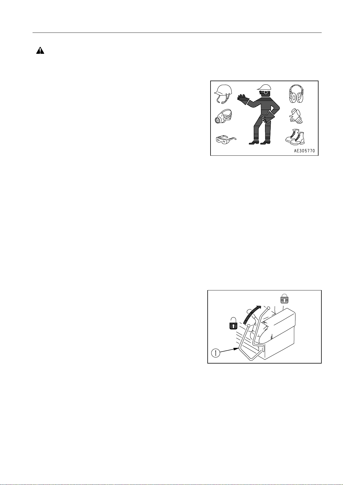
CLOTHING AND PERSONAL PROTECTIVE ITEMS
● Avoid loose clothing, jewellery, and loose long hair. They can
catch on contr ols or in movi ng parts and cau se ser ious injur y
or death. Also, do not wear oily clo ths beca us e they are fla mmable.
● Wear a hard hat, safety glasses, safety shoes, mask or
gloves when operating or maintaining the machine. Always
wear safety goggles, hard hat and heavy gloves if your job
involves scattering metal chips or minute materials <—> this
is so particularly when driving pins with a hammer and when
cleaning the air cleaner element with compressed air.
● Check also that there is no one near the machine.
Driving in pins, see “ REPLACEMENT AND INVERSION
OF BUCKET” on page 131.
Cleaning of air cleaner elem ent, see “WH EN REQUIRED”
on page 194.
UNAUTHORISED MODIFICATION
Any modificati on made withou t authorisat ion from Kom atsu can
create hazards.
Before making a modi fication, cons ult your Koma tsu distributor.
Komatsu will not be respon sible for any in jury or dama ge caused
by any unauthorised modification.
ALWAYS APPLY LOCK WHEN LEAVING OPERATOR’S SEAT
● When standing up from the operator’s seat, always plac e the
safety lock lever securely in the LOCK position. If you accidentally touch the travel or swing lever when they are not
locked, the work equipme nt may sudden ly move and cau se
serious injury or damage.
● When leaving the machine, lower the work e quipment com-
pletely to the ground, set the safety lock lever to the LOCK
position, then stop the engine and use the key to lock all the
equipment. Always take the key with you.
Work equipment posture see “PARKING THE MACHINE”
on page 133.
AB30576C
19
GENERAL PRECAUTIONS SAFETY
WARNING: For reasons of safety, always follow these safety precautions.
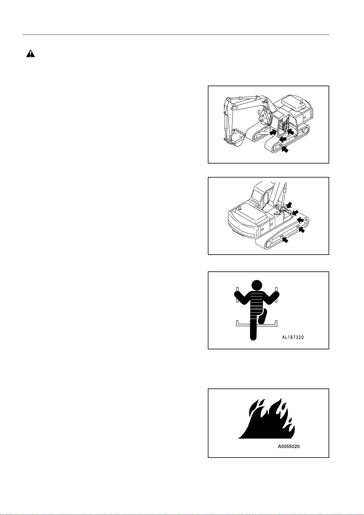
MOUNTING AND DISMOUNTING
● NEVER jump on or off the mac hine. NEVER get on or off a
moving machine.
● When mounting or dismounting, always face the machine and
use the handrails, machine or track frame steps, and track
shoes.
● Do not hold any control levers when getting on or off the
machine.
AM088940
● Ensure safety by al ways ma intaining at leas t three- point con -
tact of hands and feet with the handrails, steps or track shoes.
● Always remove an y oil or mud f rom the han drails, steps and
track shoes. If they are damaged, repair them and tighten any
loose bolts.
● If grasping the door handrail when mounting or dismounting
or moving on the track, open and lock the door securely in the
open position. Otherwise, the door may move suddenly, causing you to lose balance and fall.
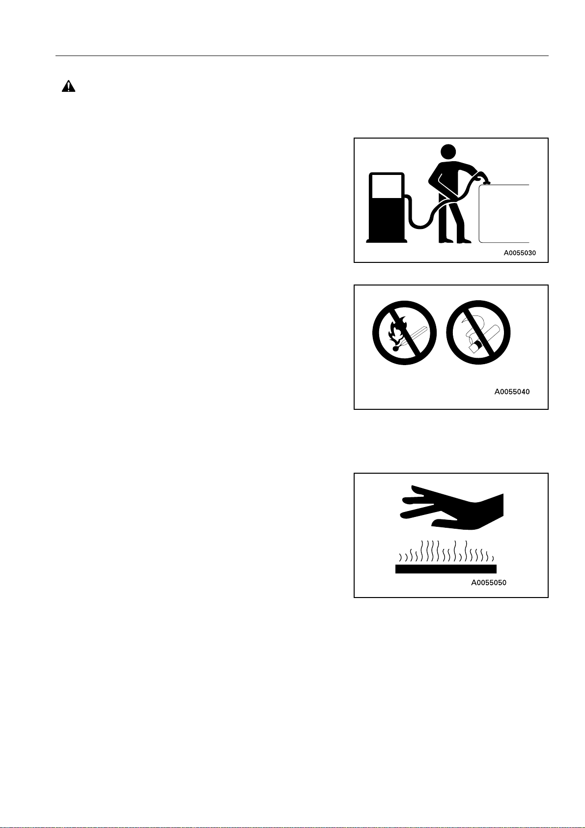
FIRE PREVENTION FOR FUEL AND OIL
Fuel, oil, and antifreeze can be ignite d by a fla me. Fuel is particularly FLAMMABLE and can be HAZARDOUS.
● Keep flames away from flammable fluids.
● Stop the engine and do not smoke when refuelling.
AM088950
20
SAFETY GENERAL PRECAUTIONS
WARNING: Failure to follow these safety precautions may lead to a serious accident.
● Tighten all fuel and oil caps securely.
● Refuelling and o iling should be carried ou t in well ventilated
areas.
● Keep oil and fuel in a secure place and do not allow unauthor-
ised persons to enter.
PRECAUTIONS WHEN HANDLING AT HIGH TEMPERATURES
● Immediately after operations are stopped, the engine coolant,
engine oil, and hydraulic oil are at high temperatures, and are
still under pressure. Attempting to remove the cap, drain the
oil or water, or replace the filters may lead to s erious burns.
Always wait for the temperature to go down, and follow the
specified procedures when carrying out these operations.
● To prevent hot water from spurting out:
❍ Turn engine off.
❍ Allow water to cool.
❍ Slowly loosen cap to relieve pressure before removing.
● To prevent hot oil from spurting out:
❍ Turn engine off.
❍ Allow oil to cool.
❍ Slowly loosen cap to relieve pressure before removing.
21
GENERAL PRECAUTIONS SAFETY
WARNING: For reasons of safety, always follow these safety precautions.
ASBESTOS DUST HAZARD PREVENTION
Asbestos dust can be HAZARDOUS to your health if it is inhaled.
Your Komatsu machin e and genu ine Kom atsu spare parts do not
contain any asbestos. Use only genuine Komatsu spare parts. If
spare parts containing asbestos ar e used, th e followin g precautions must be observed:
● NEVER use compressed air for cleaning.
● Use water for cleaning to keep down the dust.
● Operate the machine with the wind to your back, wh enever
possible.
● Use an approved respirator if necessary.
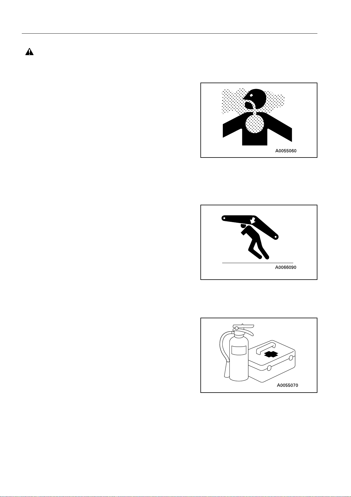
CRUSHING OR CUTTING PREVENTION
Do not enter, or put your hand or arm or any other part of your
body between movable parts such as between the work equipment and cylinders, or between the machine and work equipment.
If the work equipment is operated, the clearance will change and
this may lead to serious damage or personal injury.
FIRE EXTINGUISHER AND FIRST AID KIT
Know how to use fire extinguisher (if installed).
Provide a first aid kit at the storage point.
Know what to do in the event of a fire.
Be sure you know the phone numbers of persons you should con-
tact in case of an emergency.
22
SAFETY GENERAL PRECAUTIONS
WARNING: Failure to follow these safety precautions may lead to a serious accident.
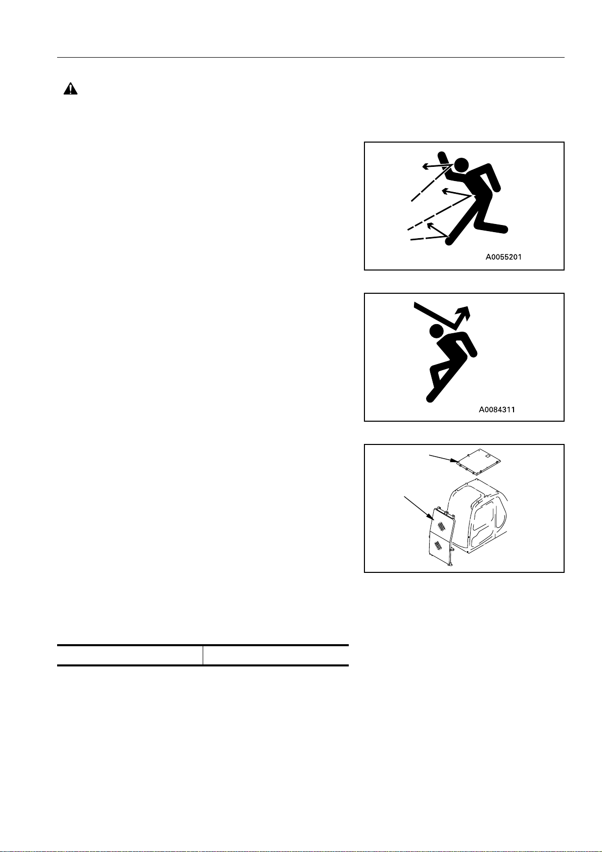
PROTECTION AGAINST FALLING OR FLYING OBJECTS
If there is any danger of falli ng or fly ing ob jects hit ting the o perator, install protective guards in place to protect the operator as
required for each pa rticular situation.
● For work with breakers, install a front guard on the wind-
shield. Also, place a laminate coating sheet over the windshield.
● For demolition or shear work, install a front guard on the
windshield and a top guard on the cab. Also, place a laminate
coating sheet over the windshield.
● For work in mines, quarries, demolition, tunnels or other
places where there is danger of falling rocks, put FOPS (falling object protective structure) in place. Also, place a laminate coating sheet over the windshield.
The above comments ar e made with regards to typical wor king conditions. By all means you should put on other guards if
required by conditions at your particular site.
For details of safety guards, please contact your Komatsu distributor.
Also, even for other types of work, if there is any danger of
being hit by falling or flying objects or of objects entering the
operator’s cab, select and i nstall a guard that matches the
working conditions.
Be sure to close the front window before commencing work.
Level 1 acceptance is intended for protection from small fall-
ing rocks, flying objects and other debris encountered in operations such as highway mainten ance, landscaping and light
construction site services
Level 1 Guards:
❍ Fitted directly onto the roof and front of the cab.
(B)
(C)
AB30052C
(B): Top guard (C): Front guard (I)
23
GENERAL PRECAUTIONS SAFETY
WARNING: For reasons of safety, always follow these safety precautions.
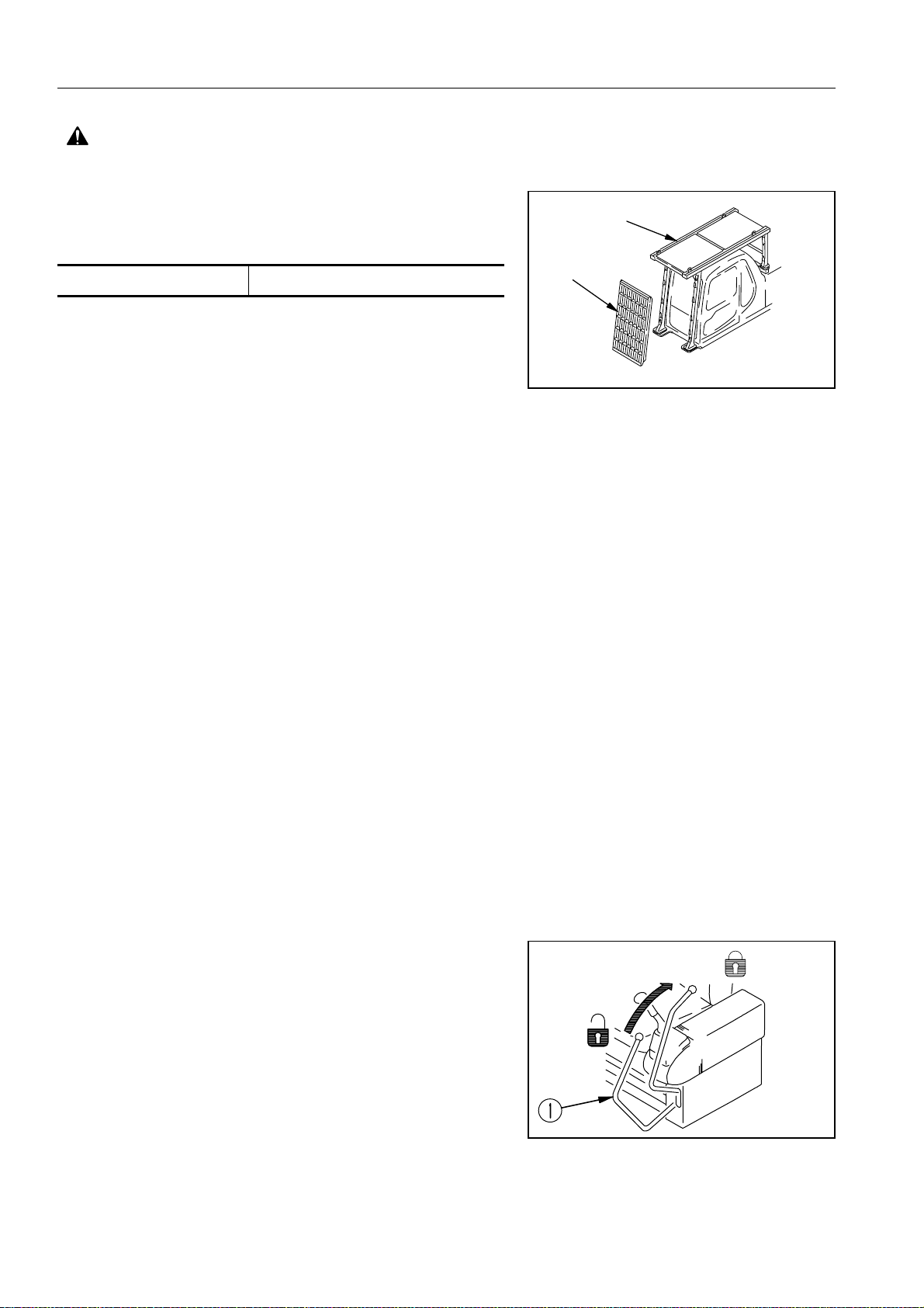
When carrying out the above operations, make sure to keep
all persons other than the operator outside the range of falling
or flying objects. Be particular ly sure to ma inta in a prop er dis-
(A)
tance when carrying out shear operations.
(A): FOPS (B) Front guard
Level 2 acceptance is intended for protection from large falling rocks, flying objects and other debris encountered in operations such as demolition work, building constr uctions and
general heavy site work.
Level 2 Guards
❍ Fops fitted directly to the revolving frame
❍ Front guard fitted directly to front of the fops
NOTE: The above guards are the minimum required for typical
working conditions as described above and are in
accordance with the lates t requirements of ISO/DIS
10262 (draft standard).
PRECAUTIONS FOR ATTACHMENTS
● When installing and using an optional attachment, read the
instruction manual for the attachment and the information
related to attachments in this manual.
(B)
AB30053C
● Do not use attachments that are not authorised by Komatsu
or your Komatsu distributor. Use of unauthorised attachments
could create a safety problem and adversely affect the proper
operation and useful life of the machine.
● Any injuries, accidents, product failures resulting from the use
of unauthorised attachmen ts will not be the resp onsibilit y of
Komatsu.
MACHINES WITH ACCUMULATOR
On machines equipped with an accumulator, for a short time after
the engine is stopped , the work e quipment will lo wer under its
own weight when the work equipment control lever is shifted to
LOWER. After the engine is stopped, set the safety lock lever to
the lock position (and also lock the attachment pedal with the lock
pin).
When releasing the pressure inside the work equipment circuit on
machines equipped with an accumulator, follow the procedure
given in the inspection and maintenance section.
Method of releasing pressure see “HANDLING THE
ACCUMULATOR” on page 94.
AB30576C
The accumulator is filled with high-pressure nitrogen gas, and it is
extremely dang erous if it is hand led in th e wrong w ay. Always
observe the following precautions.
24
SAFETY GENERAL PRECAUTIONS
WARNING: Failure to follow these safety precautions may lead to a serious accident.
● Never make any hole in the accumulator or expose it to flame
or fire.
● Do not weld anything to the accumulator.
● When carrying ou t disassembly or maint enance of the accu-
mulator, or when disposing of the accumulator, it is necessary
to release the gas from the accumulator. A special air bleed
valve is necessary for this operation, so please contact your
Komatsu distributor.
Gas in accumulator see “HANDLING THE ACCUMULATOR” on page 94.
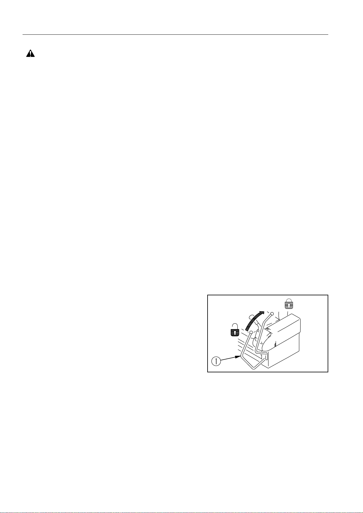
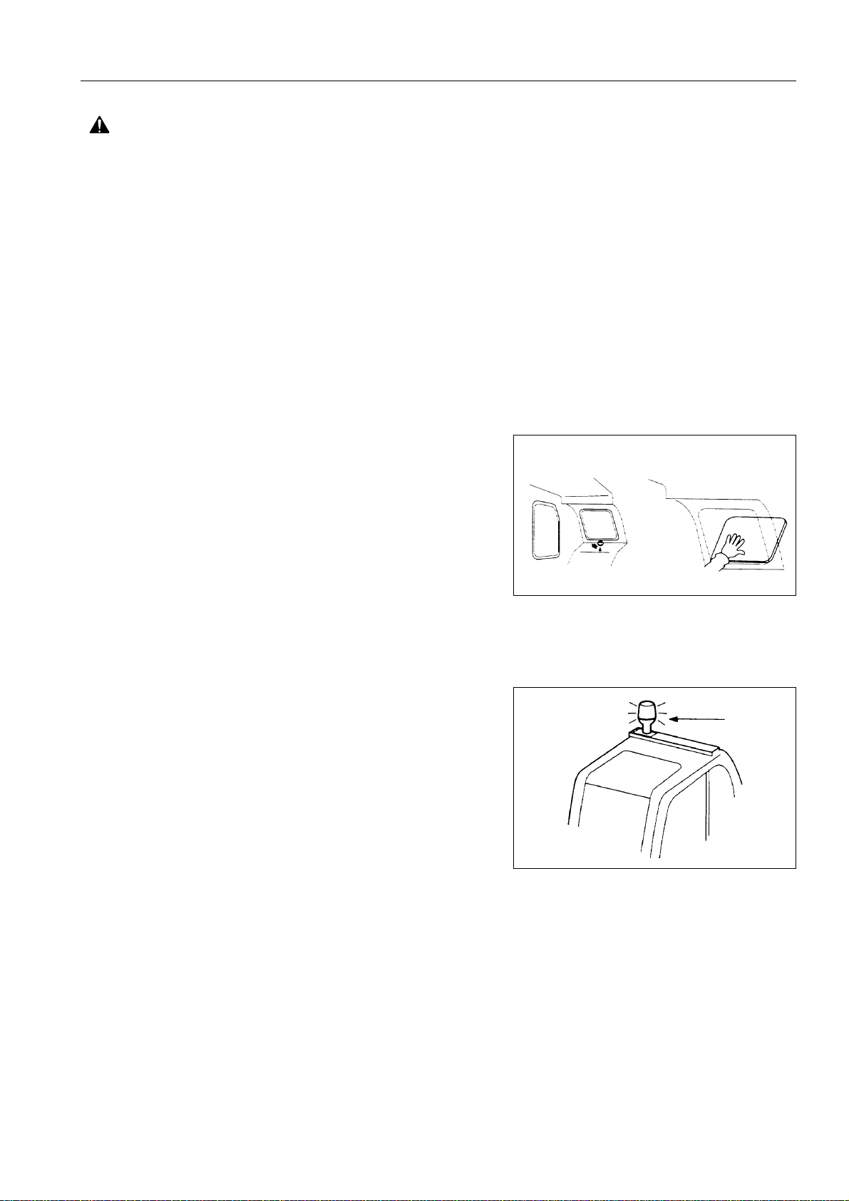
EMERGENCY EXIT
● When exit by normal means is prevented in an eme rgency
you can get out through the emergency exit (rear window).
● Pull the ring at the b ottom of the window and remove strip.
This will allow you to push out glass.
ROTATING BEACON (Option)
When the machine is operated on or beside a road, a rotating
beacon is required to avoid a traffic accident.
Contact your Komatsu distributor to install beacon lamp.
ELECTROMAGNETIC INTERFERENCE
When this machine is o perat ing cl ose to a s ource of high el ectromagnetic interference, such as a radar station, some abnormal
phenomena may be observed.
● The display on the monitor panel may behave erratically.
● The warning buzzer may sound.
These effects do not signify a malfunction and the machine will
return to normal as soon as the source of interference is removed.
25
PRECAUTIONS DURING OPERATION SAFETY
WARNING: For reasons of safety, always follow these safety precautions.
PRECAUTIONS DURING OPERATION
BEFORE STARTING ENGINE
SAFETY AT WORKSITE
● Before starting the engine , thoroughly check the area fo r any
unusual conditions that could be dangerous.
● Before starting the engine, examine the terrain and soil condi-
tions of the worksite. Determine the best and safest method
of operation.
● Make the slope as horizontal as possible before co ntinuing
operations.
● If you need to operate on a street, protect pedestrians and
cars by designating a person for worksite traffic duty or by
instal ling fences around the worksite.
● If water lines, gas lines, an d high- voltage electric al lines may
be buried u nder the wor ksi te, contac t ea ch u tili ty and iden tify
their locations. Be careful not to sever or cut any of these
lines.
● Check the depth and flow of water before o perating in water
or crossing a river. NEVER be in water which is in excess of
the permissible water depth.
Permissible water depth see “PRECAUTIONS FOR
OPERATION” on page 127.
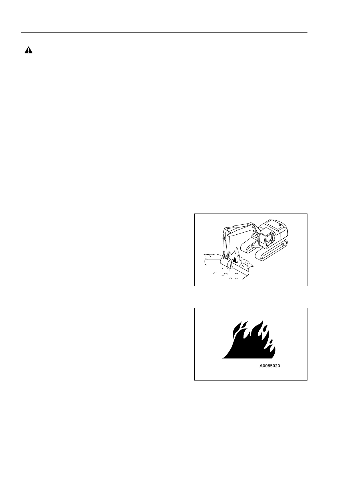
FIRE PREVENTION
● Thoroughly remove wood chips, leaves, paper and other
flammable things accumulate d on the engin e compartment.
They could cause a fire.
● Check fuel, lu br ic at i on, an d hy draulic system s f or le aks. H ave
any leaks repaired. Wipe up any excess oil, fuel or other flammable fluids.
Check point see “WALK-AROUND CHECK” on page 95.
● Be sure a fire extinguisher is present and working.
AE341030A
IN OPERATOR’S CAB
● Do not leave tools or spare parts lying around i n the opera-
tor’s compartment. They may damage or break the control
levers or switch es. Always put them in the tool box on the left
or right side of the machine.
26
SAFETY PRECAUTIONS DURING OPERATION
WARNING: Failure to follow these safety precautions may lead to a serious accident.
● Keep the cab f loor, controls, st eps and handrails free of oil ,
grease, snow, and excess dirt.
Handling sea t belt →see “USING THE SEAT BELT” on
page 103.
VENTILATION FOR ENCLOSED AREAS
● If it is necessary to s tart the engine within an enc losed area,
provide adequate ven tilat ion. Exha ust fu mes from th e eng ine
can KILL.
PRECAUTIONS FOR MIRRORS, WINDOWS AND LIGHTS
● Remove all dirt from the surfac e of the wi ndows and lights to
ensure that you can see well.
● Adjust the rear view mirror so that you can see clearly from
the operator’s seat, and always keep the surface of the mirror
clean. If any glass is broken, replace it with a new part.
● Check that the head lamps and working lamps are installed to
match the oper ating condit ions. Check a lso tha t they li ght up
properly.
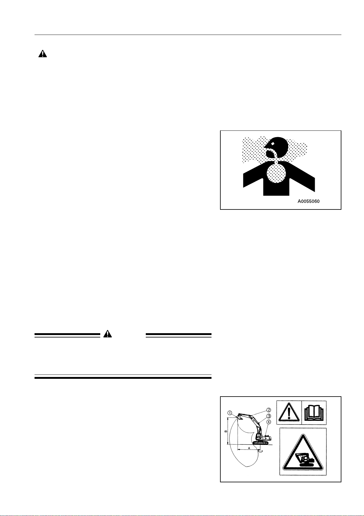
PRECAUTIONS WHEN HANDLING (TWO PIECE BOOM)
When operating the boom arm 2-piece type, select a specialist
operator and do not allow any other person to operate the
machine.
● Check that the ground insi de the operating range is flat and
firm.
● Always operate the work equipment slowly.
WARNING
Especially when lowering the work equipment, move it as
slowly as possible to prevent any shock to the machine
(operate the w ork e quip ment i n th e sam e wa y as when o perating a crane).
● Pay attention to warning decal in the cab.
27
PRECAUTIONS DURING OPERATION SAFETY
WARNING: For reasons of safety, always follow these safety precautions.
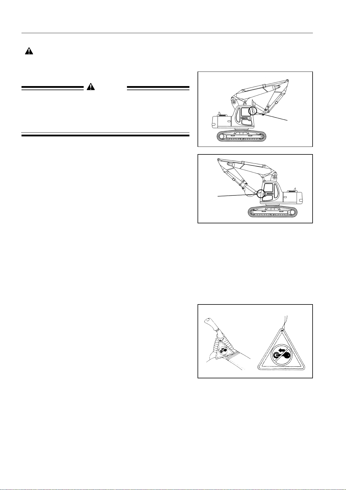
WARNING
If the bucket is operated in a certain way, it comes in contact
with the machine body (operator ’s cab, upper boom, cy linders and undercarriage). When operating the work equipment, take sufficient care not to bring it in contact with the
machine body.
Interference
OPERATING MACHINE
WHEN STARTING THE ENGINE
● Walk around your machine again just before mounting it, to
check for people and objects that might be in the way.
● NEVER start the engine if a warning tag has been attached to
the wrist control.
● When starting the engine, sound the horn as an alert.
● Start and operate the machine only while seated.
● Fasten your seat belt securely at all times during operation.
● Do not allow anyone other than the operator to ride in the cab
or on the machine body.
Interference
● For machines equipped with a travel alarm buzzer, check that
the warning device operates correctly.
28
 Loading...