

Page 1

UEAM004904
Operation &
Maintenance Manual
PC210-8
PC210LC, PC210NLC-8
PC230NHD-8
PC240LC, PC240NLC-8
HYDRAULIC EXCAVATOR
SERIAL NUMBER
PC210, PC210LC, PC210NLC-8
PC230NHD-8
PC240LC, PC240NLC-8
PC240LC, PC240NLC-8
- K50001 and up
- K50001 and up
- K50001 and up
- 10001 and up
WARNING
Unsafe use of this machine may cause serious injury or
death. Operators and maintenance personnel must read
this manual before operating or maintaining this
machine. This manual should be kept inside the cab for
reference and periodically reviewed by all personnel who
will come into contact with the machine.
Page 2

Page 3

FOREWORD
11
Page 4
FOREWORD FOREWORD
FOREWORD 1
This manual provides rules and guidelines which will help you use this machine safely and effectively. The precautions in this manual must be followed at all times when performing operation and maintenance. Most acciden ts
are caused by the failure to follow fundamental safety rules for the operation and maintenance of machi nes. Accidents can be prevented by knowing beforehand conditio ns that may cause a haz ard when performing op eration
and maintenance.
WARNING
Before beginning operation or maintenance, operators and maintenance personnel must always observe
the following points.
Read this manual thoroughly and understand its contents fully.
Read the safety messages and safety labels given in this manu al carefully so that they shou ld be understood fully.
Keep this manual at the storage location for the Operation and Maintenance Manual given below so that
all personnel involved in working on the machine can consult it periodically.
In case this manual should be lost or damaged, immediat ely contact Komatsu or your Komatsu distributor
to obtain a new copy.
When you sell the machine, make sure that this manual should be provided to the new owner together
with the machine.
In this manual, measurements are expressed in internationa l standard units (SI). For the reference purpose, weight units used in the p ast are also displayed in ( ).
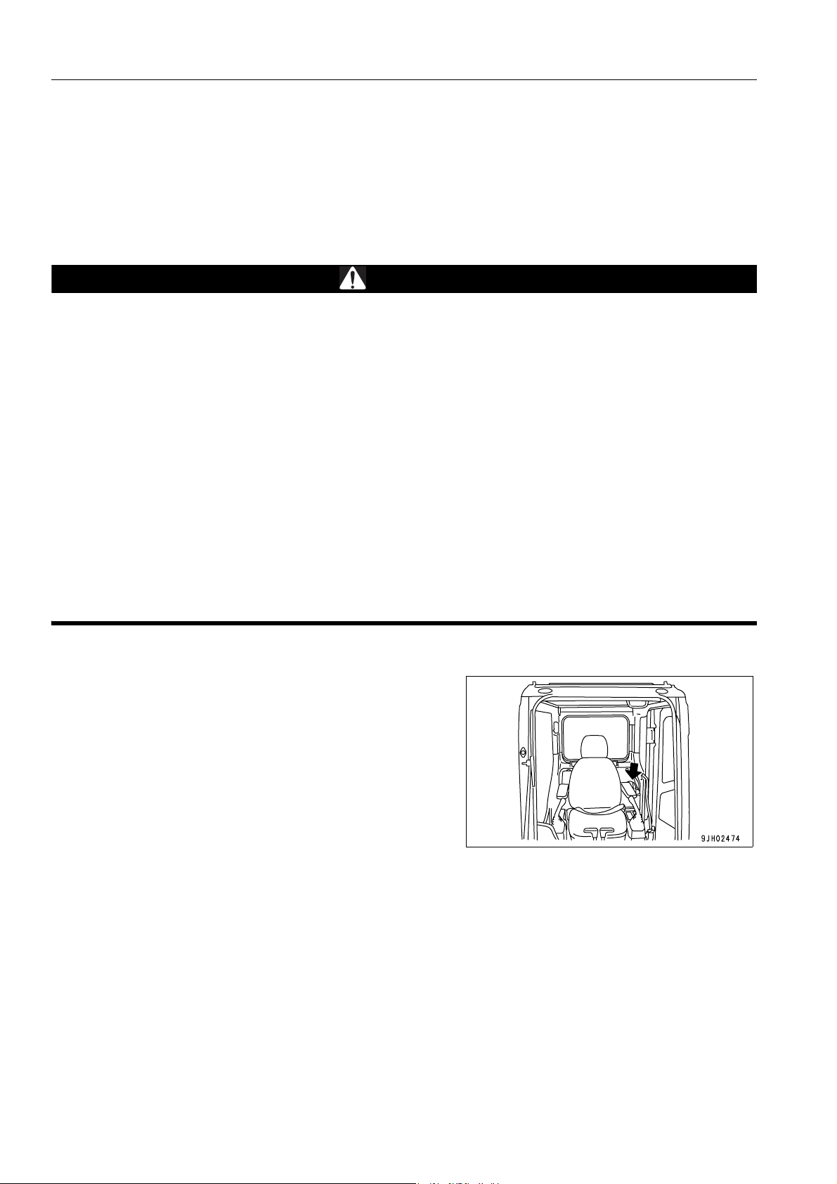
Storage location fo r the Operation and Maintenance Manual:
magazine box on the left side of the operator's seat.
1-4
Page 5

FOREWORD SAFETY INFORMATION
SAFETY INFORMATION 1
To enable you to use this machine safely, safety precautions and labels are given in this manual and affixed to the
machine to give explanations of situations involving potential hazards and of the methods of avoiding such situations.
Signal words
The following signal words are used to inform you that there is a potential hazardous situation that may lead to personal injury or damage.
In this manual and on machine labels, the following signal words are used to express the potential level of hazard.
DANGER
WARNING
CAUTION
Example of safety message using signal word
Indicates an imminently hazardous situation which, if not avoided, will result in death
or serious injury.
Indicates a potentially hazardous situation which, if not avoided, could result in death
or serious injury.
Indicates a potentially hazardous situation which, if not avoided, may result in minor or
moderate injury. This word is used also to alert against unsafe practices that may
cause property damage.
WARNING
When standing up from the operator's seat, always place the lock lever in the LOCK position.
If you accidentally touch the control levers when they are n ot locked, this may ca use a serious inju ry or
death.
Other signal words
In addition to the above, the following signal words are used to indicate precaution s that shou ld be followed to protect the machine or to give information that is useful to know.
NOTICE
REMARKS
This word is used for precautions that must be taken to avoid actions which could shorten
the life of the machine.
This word is used for information that is useful to know.
1-5
Page 6
SAFETY INFORMATION FOREWORD
q Safety labels
Safety labels are affixed to the machine to inform the operator or maintenance worker on the spot when carrying
out operation or maintenance of the machine that may involve hazard.
This machine uses “Safety labels using words“ and “Safety labels using pictograms“ to indicate safety pr ocedur es.
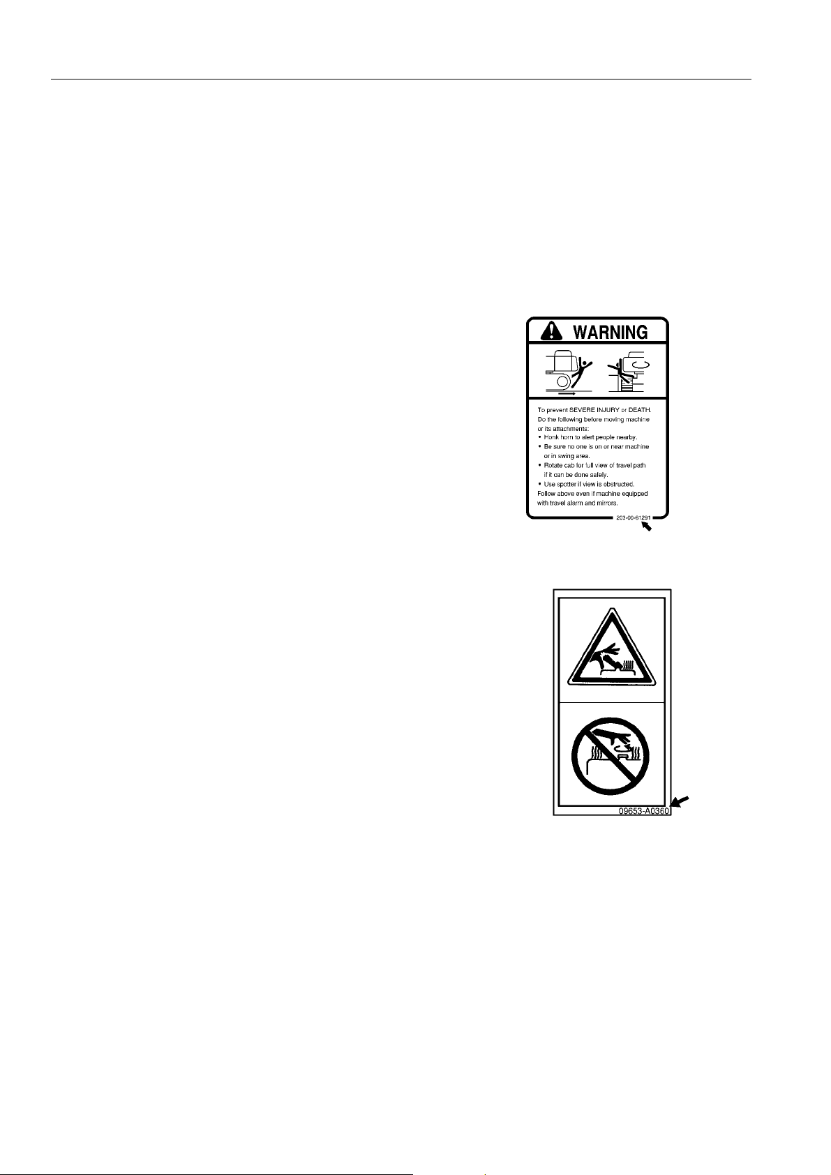
Example of safety label using words
Safety labels using pictogram
Part No.
Safety pictograms use a picture to expre ss a level of hazardous condition equivalent to the signal word. These safety pictograms use pictures in order to let the operator or maintenance
worker understand the level and type of h azardous condition at
all times. Safety pictograms show the type of hazardous condition at the top or left side, and the method of avoiding the hazardous condition at the bottom or right side. In addition, the
type of hazardous condition is displayed inside a triangle and
the method of avoiding the hazardous condition is shown
inside a circle.
Part No.
Komatsu cannot predict every circumstance that might involve a potential hazard in operation and maintena nce.
Therefore, the safety messages in this manual and on the machine may not include all po ssible safety precautions.
If any procedures or actions not specifically recommended or allowed in this manual are used, it is your responsibility to take the necessary steps to ensure safety.
In no event should you engage in prohibited uses or actions described in this manual.
The explanations, values, and illustrations in this manual were prepared based on the latest information available
at that time. Continuing improvements in the design of this machine can lead to changes in detail which may not
be reflected in this manual. Consult Komatsu or your Komatsu distributor for the latest available information of
your machine or for questions regarding information in this manual.
The numbers in circles in the illustrations correspond to the numbers in ( ) in the text. (For example: 1 -> (1))
1-6
Page 7
FOREWORD SAFETY INFORMATION
NOISE (PC210,210LC,210NLC, PC230NHD) 1
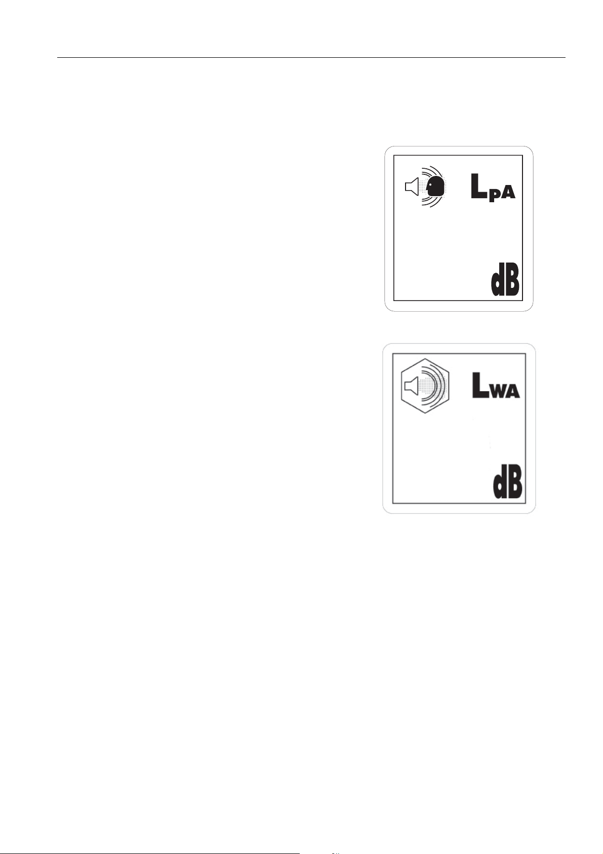
Two labels indicating the machine noise level are affixed on the machine.
q Sound pressure level at the operator’s station, measured
according to ISO6396 (Dynamic test method,simulated
working cycle).
69
q Sound power level emitted by the machine, measured
according to ISO 6395 (Dynamic test method, simulated
working cycle). This is the guaranteed value as specified
in European directive 2000/14/EC.
102
1-7
Page 8

SAFETY INFORMATION FOREWORD
NOISE (PC240LC,240NLC) 1
Two labels indicating the machine noise level are affixed on the machine.
q Sound pressure level at the operator’s station, measured
according to ISO6396 (Dynamic test method,simulated
working cycle).
q Sound power level emitted by the machine, measured
according to ISO 6395 (Dynamic test method, simulated
working cycle). This is the guaranteed value as specified
in European directive 2000/14/EC
1-8
Page 9

FOREWORD SAFETY INFORMATION
Vibration levels 1
When used for its intended purpose, levels of vibration for the earth-moving machine transmitted from the operator’s seat are lower than or equal to the tested vibrations for the relative machinery class in compliance with ISO
7096.
The actual acceleration value for the hands and arms is less than or equal to 2.5 m/s². The actual acceleratio n
value for the body is less than or equal to 0.5 m/s².
These values were determined using a representative machine and measured during the typical operating condi-
tion indicated below according to the measurement procedures that are defined in the standards ISO 2631/1 and
ISO 5349.
Operating condition:
Excavating (Digging-loading-rotating-unloading-rotating)
Guide to Reduce Vibration Levels on Machine 1
The following guides can help an operator of this machine to reduce the whole body vibration levels:
1. Use the correct equipment and attachments.
2. Maintain the machine accordin g to this manual
Q Tension of crawler (for crawler machines)
Q Brake and steering systems
Q Controls, hydraulic system and linkages
3. Keep the terrain where the machine is working and traveling in good condition
Q Remove any large rocks or obstacles
Q Fill any ditches and holes
Q Site manager should provide machine operators with machine and schedule time to maintain terrain con-
ditions
4. Use a seat that meets ISO 7096 and keep the seat maintained and adjusted
Q Adjust the seat and suspension for the weight and size of the operator
Q Wear seat belt
Q Inspect and maintain the seat suspension and adjustme nt mec ha nis ms
5. Steer, brake, accelerate, and move the attachment levers and pedals slowly so that the machine moves
smoothly
6. Adjust the machine speed and travel path to minimize the vibration level
Q When pushing with bucket or blade, avoid sudden loading; load gradually
Q Drive around obstacles and rough terrain conditions
Q Slow down when it is necessary to go over rough terrain
Q Make the curve radius of traveling path as large as possible
Q Travel at low speed when traveling around sharp curves
1-9
Page 10

SAFETY INFORMATION FOREWORD
7. Minimize vibrations for long work cycle or long distance traveling
Q Reduce speed to prevent bounce
Q Transport machines long distances between worksites
8. The following guidelines can be effective to minimize risks of low back pain
Q Operate the machine only when you are in good health.
Q Provide breaks to reduce long periods of sitting in the same posture
Q Do not jump down from the cab or machine
Q Do not repeatedly handle and lift loads
1-10
Page 11
FOREWORD INTRODUCTION
INTRODUCTION 1
This Komatsu machine is designed to be used mainly for the following work:
q Digging work
q Leveling work
q Ditching work
q Loading work
q Demolition work
See the section “RECOMMENDED APPLICATIONS (3-156)“ for further details.
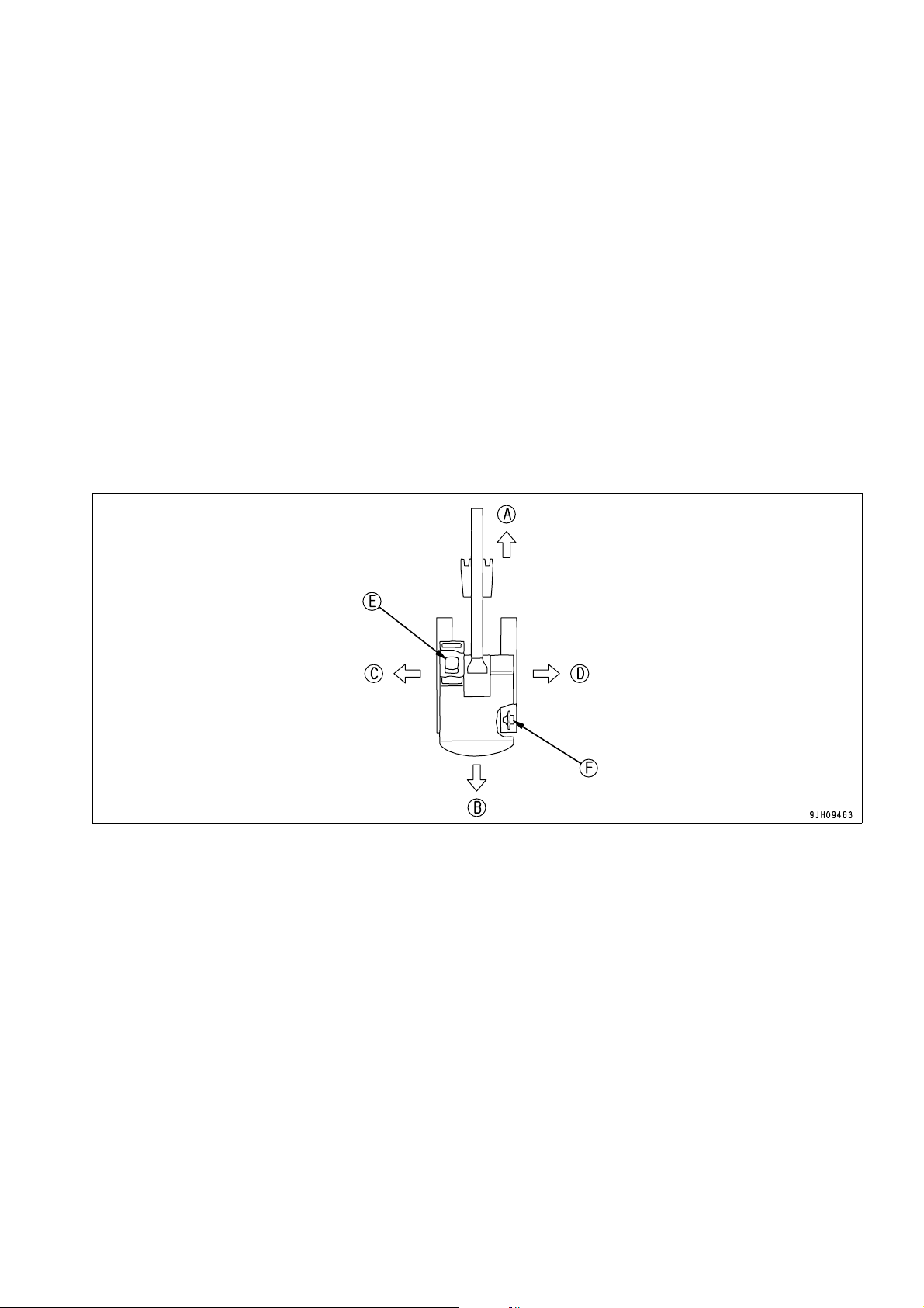
DIRECTIONS OF MACHINE 1
(A) Front (E) Operator's seat
(B) Rear (F) Sprocket
(C) Left
(D) Right
In this manual, the terms front, rear, left, and right refer to the travel direction as seen from the operator's seat
when the operator's seat is facing the front and the sprocket is at the rear of the machine.
1-11
Page 12

INTRODUCTION FOREWORD
BREAKING-IN THE NEW MACHINE 1
NOTICE
Your Komatsu machine has been thoroughly adjusted and tested before shipment from the factory. However, ope rating the machine under full load before bre aking the machine in can adverse ly affect the perf ormance and shorten the machine life.
Be sure to break in the machine for the initial 100 hours (as indicated on the service meter).
Make sure that you fully understand the content of this manual, and pay careful attention to the following points
when breaking in the machine.
q Run the engine at idle for 15 seconds after starting it. Dur-
ing this time, do not operate the control levers or fuel control dial.
q Idle the engine for 5 minutes after starting it up.
q Avoid operation with heavy loads or at high speeds.
q Immediately after starting the engine, avoid sudden starts,
sudden acceleration, unnecessary sudden stops, and sudden changes in direction.
1-12
Page 13
FOREWORD PRODUCT INFORMATION
PRODUCT INFORMATION 1
When requesting service or ordering replacement parts, please inform your Komatsu distributor of the following
items.
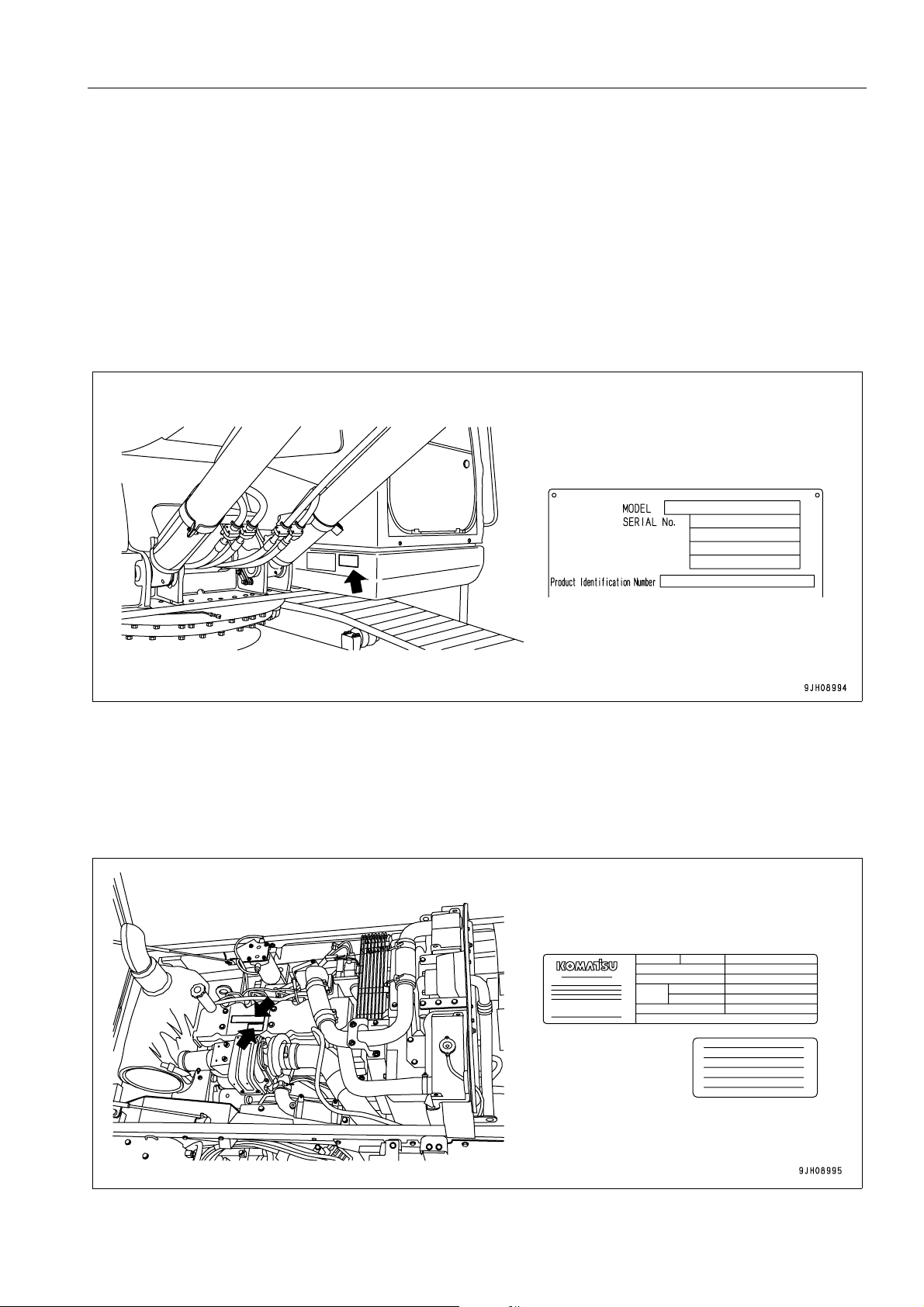
PRODUCT IDENTIFICATION NUMBER (PIN)/MACHINE SERIAL NO. PLATE 1
On the bottom right of the operator's cab
The design of the nameplate differs according to the territory.
ENGINE SERIAL NUMBER PLATE AND ITS LOCATION 1
On the top of the engine cylinder head cover.
(The EPA auxiliary nameplate is on the top of the engine cylinder head cover.)
EPA: Environmental Protection Agency, U.S.A.
1-13
Page 14

PRODUCT INFORMATION FOREWORD
SERVICE METER LOCATION 1
On top of the machine monitor
TABLE TO ENTER SERIAL NO. AND DISTRIBUTOR 1
Machine serial No.
Engine serial No.
Product Identification Number
Manufacturers name:
Address:
Distributor
Address
Phone
KOMATSU UK Ltd.
Durham Road
Birtley
Chester-Le street
County Durham DH32QX
United Kingdom
1-14
Page 15
FOREWORD PRODUCT INFORMATION
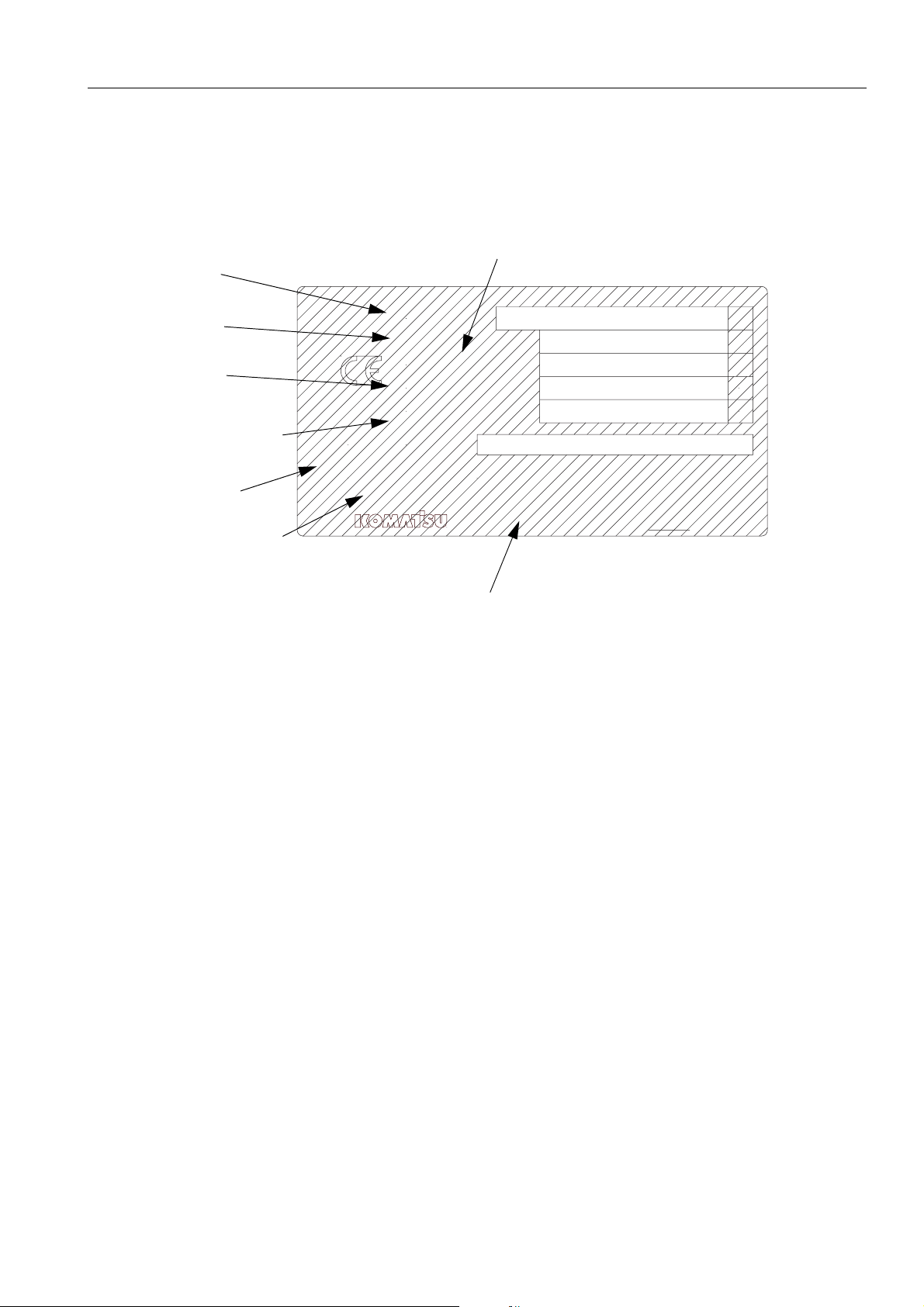
MACHINE SERIAL PLATES 1
STANDARD SERIAL PLATE 1
MANUFACTURING YEAR
MODEL
SERIAL
WEIGHT
ENGINE POWER
PRODUCT ID
NUMBER
MANUFACTURER
MODEL
SERIAL No.
MANUFACT. YEAR
MASS
ENGINE POWER
Product Identification Number
MANUFACTURER
Manufactured by Komatsu UK Ltd.
for Komatsu Ltd.,Tokyo,Japan
Komatsu UK Ltd, Birtley, Co Durham, United Kingdom
kg
kW
205-00-K1291
1-15
Page 16

CONTENTS
CONTENTS
FOREWORD
FOREWORD.........................................................................................................................................................1-4
SAFETY INFORMATION......................................................................................................................................1-5
NOISE (PC210,210LC,210NLC, PC230NHD)............................................................................................1-7
NOISE (PC240LC,240NLC)........................................................................................................................ 1-8
VIBRATION LEVELS................................................ ... .... ... ... ....................................... ... ... .... ....................1-9
GUIDE TO REDUCE VIBRATION LEVELS ON MACHINE ................ ..............................................1-9
INTRODUCTION................................................................................................................................................. 1-11
DIRECTIONS OF MACHINE .................................................................................................................... 1-11
BREAKING-IN THE NEW MACHINE ....................................................................................................... 1-12
PRODUCT INFORMATION................................................................................................................................1-13
PRODUCT IDENTIFICATION NUMBER (PIN)/MACHINE SERIAL NO. PLATE...................................... 1-13
ENGINE SERIAL NUMBER PLATE AND ITS LOCATION.......................................................................1-13
SERVICE METER LOCATION .................................................................................................................1-14
TABLE TO ENTER SERIAL NO. AND DISTRIBUTOR ............................................................................ 1-14
MACHINE SERIAL PLATES..................................................................................................................... 1-15
STANDARD SERIAL PLATE...........................................................................................................1-15
SAFETY
SAFETY INFORMATION......................................................................................................................................2-2
SAFETY LABELS.................................................................................................................................................2-4
LOCATION OF SAFETY LABELS..............................................................................................................2-4
SAFETY LABELS ..................... ... ....................................... ... ....................................... ... ... ........................2-5
SAFETY INFORMATION....................................................................................................................................2-12
SAFETY RULES.............................................................................................................................. 2-12
IF PROBLEMS ARE FOUND ..........................................................................................................2-12
WORKING WEAR AND PERSONAL PROTECTIVE ITEMS .......................................................... 2-12
FIRE EXTINGUISHER AND FIRST AID KIT ................................................................................... 2-12
SAFETY EQUIPMENT ....................................................................................................................2-13
KEEP MACHINE CLEAN.................................................................................................................2-13
KEEP OPERATOR'S COMPARTMENT CLEAN............................................................................. 2-13
LEAVING OPERATOR'S SEAT WITH LOCK.................................................................................. 2-13
HANDRAILS AND STEPS...............................................................................................................2-14
MOUNTING AND DISMOUNTING...................................... ... ... ... .... ... ... ... ... .... ... ... ......................... 2-15
NO PERSONS ON ATTACHMENTS .............................. .......................................... .... ... ... ... ... .... .. 2-15
DO NOT GET CAUGHT IN ARTICULATED PORTION ............... .... ... ... ... ... .... ... ... ... .... ... ... ... ... .... .. 2-15
BURN PREVENTION ......................................................................................................................2-15
1-16
Page 17

CONTENTS
ACTION IF FIRE OCCURS .............................................................................................................2-17
WINDSHIELD WASHER FLUID...................................................................................................... 2-17
FALLING OBJECTS, FLYING OBJECTS AND INTRUDING OBJECTS PREVENTION................2-17
ATTACHMENT INSTALLATION...................................................................................................... 2-17
ATTACHMENT COMBINATIONS ................................................................................................... 2-18
CAB WINDOW GLASSES............................................................................................................... 2-18
UNAUTHORIZED MODIFICATIONS............................................................................................... 2-18
SAFETY AT JOBSITE.............................................. .... ... ... ... .... ... ... ....................................... ......... 2-18
WORKING ON LOOSE GROUND .................................................................................................. 2-18
DISTANCE TO HIGH VOLTAGE CABLES ..................................................................................... 2-19
ENSURE GOOD VISIBILITY..................................................................... ... ... ... .... ... ... ... ... .... ... ... ... 2-19
VENTILATION FOR ENCLOSED AREA......................................................................................... 2-20
SIGNALMAN'S SIGNAL AND SIGNS ............................................................................................. 2-20
EMERGENCY EXIT FROM OPERATOR'S CAB ............................................................................ 2-20
ELECTROMAGNETIC INTERFERENCE........................ ... ... .... ... ... ... ... .... ... ... ... .... ... ... ... ... .... ... ... ... 2-20
ASBESTOS DUST HAZARD PREVENTION .................................................................................. 2-21
SAFETY MACHINE OPERATION...................................................................................................................... 2-22
STARTING ENGINE... .... ... ... ... .... ... ... ... .... ...................................... .... ... ... ... ... .... ... ................................... 2-22
CHECKS BEFORE STARTING ENGINE..................................................................... ... ... .... ... ... ... 2-22
SAFETY RULES FOR STARTING ENGINE ................................................................................... 2-23
STARTING ENGINE IN COLD WEATHER ..................................................................................... 2-23
OPERATION............................................................................................................................................. 2-24
CHECKS BEFORE OPERATION............................. .... ... ... ... .... ... .......................................... ......... 2-24
SAFETY RULES FOR CHANGING MACHINE DIRECTIONS........................................................ 2-24
SAFETY RULES FOR TRAVELLING.............................................................................................. 2-25
TRAVELLING ON SLOPES............................................................................................................. 2-26
OPERATIONS ON SLOPES ........................................................................................................... 2-27
PROHIBITED OPERATIONS................................ ... .... ... ... ... ....................................... ... ... .... ... ... ... 2-27
OPERATIONS ON SNOW............................................................................................................... 2-29
PARKING MACHINE....................................................................................................................... 2-29
TRANSPORTATION................................................................................................................................. 2-30
LOADING AND UNLOADING.......................................................................................................... 2-30
SHIPPING THE MACHINE.............................. ... ....................................... ... ... ... .... ... ... ... ... .... ... ...... 2-31
BATTERY ................................................................................................................................................. 2-32
STARTING ENGINE WITH BOOSTER CABLES............................................................................ 2-33
TOWING................................................................................................................................................... 2-34
SAFETY RULES FOR TOWING ..................................................................................................... 2-34
LIFTING OBJECTS WITH BUCKET............................... ... .... ... ... ... .... ... ... ... ... .... ... ... ... ............................. 2-35
SAFETY RULES FOR LIFTING OBJECTS..................................................................................... 2-35
SAFETY MAINTENANCE INFORMATION........................................................................................................ 2-36
WARNING TAG..................................................................... .... ... ... ... ... .... ... ... ................................ 2-36
KEEP WORK PLACE CLEAN AND TIDY ....................................................................................... 2-36
APPOINT LEADER WHEN WORKING WITH OTHERS.................... ... .... ... ... ... .... ... ... ... ... .... ... ... ... 2-36
STOP ENGINE BEFORE CARRYING OUT MAINTENANCE......................................................... 2-37
TWO WORKERS FOR MAINTENANCE WHEN ENGINE IS RUNNING........................................ 2-38
PROPER TOOLS ............................................................................................................................ 2-38
1-17
Page 18

CONTENTS
ACCUMULATOR............................................................................................................................. 2-39
HANDLING GAS SPRING.. ... .... ... ... ... .... ... ... ... ....................................... ... ... .... ... ... ... .... ..................2-39
PERSONNEL...................................................................................................................................2-40
ATTACHMENTS.............................................................................................................................. 2-40
WORK UNDER THE MACHINE...................................................................................................... 2-40
NOISE..............................................................................................................................................2-41
WHEN USING HAMMER ................................................................................................................2-41
WELDING WORKS .........................................................................................................................2-41
REMOVING BATTERY TERMINALS..............................................................................................2-41
SAFETY FIRST WHEN USING HIGH-PRESSURE GREASE TO ADJUST TRACK TENSION..... 2-42
DO NOT DISASSEMBLE RECOIL SPRINGS................................................................................. 2-42
SAFETY RULES FOR HIGH-PRESSURE OIL ...............................................................................2-42
OPERATION
MACHINE VIEW ILLUSTRATIONS .....................................................................................................................3-2
OVERALL MACHINE VIEW........................................................................................................................ 3-2
CONTROLS AND GAUGES....................................................................................................................... 3-3
DETAILED CONTROLS AND GAUGES..............................................................................................................3-4
MONITORING SYSTEM.............................................................................................................................3-4
BASIC OPERATION OF MACHINE MONITOR ................................................................................ 3-5
BASIC CHECK MONITORS..............................................................................................................3-9
CAUTION MONITORS ................. ... ... ....................................... ... .... ... ... ... ... ................................... 3-11
EMERGENCY MONITORS ............................................. .... ... ... ....................................... ... ... ... .... .. 3-14
METER DISPLAY PORTION...........................................................................................................3-16
MONITOR SWITCHES PORTION .................. .......................................... ...................................... 3-23
HANDLING FUNCTION SWITCHES......................... ... ... .... ... ... ... .... ... ... ... ... .... ... ... ......................... 3-32
SWITCHES...............................................................................................................................................3-68
CONTROL LEVERS AND PEDALS .........................................................................................................3-73
CEILING WINDOW...................................................................................................................................3-76
WINDSHIELD ........................................................................................................................................... 3-76
EMERGENCY ESCAPE HAMMER .......................................................................................................... 3-82
DOOR LOCK ............................................................................................................................................ 3-82
CAP WITH LOCK......................................................................................................................................3-83
DRINK BOX .............................................................................................................................................. 3-85
MAGAZINE BOX.......... ... ... .... ...................................... .... ... ... ....................................... ... ... ......................3-85
ASHTRAY.................................................................................................................................................3-85
AIR CONDITIONER CONTROLS.............................................................................................................3-86
AIR CONDITIONER CONTROL PANEL ......... ... .... ... ... ... .... ... .......................................... ... ............3-86
METHOD OF OPERATION............................................. .... ... ....................................... ... ... ... ... .... ..3-91
USE AIR CONDITIONER WITH CARE........................................................................................... 3-98
AIR CONDITIONER MAINTENANCE .................... ... ... ... .... ... ... ... .... ... ... ... ... .... ............................... 3-98
RADIO....................................................................................................................................................... 3-99
CONTROL PANEL ..........................................................................................................................3-99
CONTROLS OF RADIO ................................................................................................................3-101
USE RADIO WITH CARE.............................................................................................................. 3-103
1-18
Page 19

CONTENTS
SPACE FOR RADIO CASSETTE.................................................................................................. 3-103
AUXILIARY ELECTRIC POWER.......................... ....................................... ... .... ... ... ... .... ... ... ... ... .... ....... 3-104
24V POWER SOURCE ................................................................................................................. 3-104
12V POWER SOURCE ................................................................................................................. 3-104
FUSE ...................................................................................................................................................... 3-105
FUSIBLE LINK.......................................... ... ... ... ....................................... ... ... .... ... ................................. 3-106
CONTROLLER ....................................................................................................................................... 3-106
TOOL BOX.............................................................................................................................................. 3-106
GREASE GUN HOLDER........................................................................................................................ 3-106
MACHINE OPERATIONS AND CONTROLS................................................................................................... 3-107
BEFORE STARTING ENGINE ............................................................................................................... 3-107
WALK-AROUND CHECKS............................................................................................................ 3-107
REFUELLING PUMP.............................................................................................................................. 3-108
CHECKS BEFORE STARTING............................. ... .... ... ... ... .......................................... .............. 3-109
ADJUSTMENT............................................................................................................................... 3-116
SEAT BELT ................. ... .... ...................................... .... ... ... ....................................... ... ... .............. 3-120
OPERATIONS BEFORE STARTING ENGINE ............................................................................. 3-121
STARTING ENGINE... .... ... ... ... .... ... ... ... .... ...................................... .... ... ... ... ... .... ... ................................. 3-123
AFTER STARTING ENGINE.................................................................................................................. 3-126
WARMING UP ENGINE ................................................................................................................3-127
WARMING UP HYDRAULIC EQUIPMENT................................................................................... 3-129
OPERATION AFTER COMPLETION OF WARMING-UP OPERATION....................................... 3-135
STOPPING THE ENGINE ...................................................................................................................... 3-137
MACHINE OPERATION........................................... ... ....................................... ... ... ... .... ... ... ... .............. 3-138
PREPARATIONS FOR MOVING THE MACHINE......................................................................... 3-138
MOVING MACHINE FORWARD................................................................................................... 3-139
MOVING MACHINE BACKWARD................................................................................................. 3-140
STOPPING MACHINE..................................................... ... ... .... ...................................... ... .... ....... 3-141
STEERING THE MACHINE.................................................................................................................... 3-142
STEERING .................................................................................................................................... 3-142
SWINGING ............................................................................................................................................. 3-144
WORK EQUIPMENT CONTROLS AND OPERATIONS ........................................................................ 3-145
WORKING MODE................................................................................................................................... 3-147
PROHIBITED OPERATIONS ...... ...................................... .... ... ... ... .... ... ...................................... ........... 3-149
GENERAL OPERATION INFORMATION ................................ ... ... .... ... ... ... ... .... ... ... ... ........................... 3-151
TRAVELLING ON SLOPES.................................................................................................................... 3-153
ESCAPE FROM MUD............................................................................................................................. 3-155
TRACK ON ONE SIDE STUCK..................................................................................................... 3-155
TRACKS ON BOTH SIDES STUCK.............................................................................................. 3-155
RECOMMENDED APPLICATIONS........................................................................................................ 3-156
BACKHOE WORK......................................................................................................................... 3-156
SHOVEL WORK............................................................................................................................ 3-156
DITCHING WORK........................................................................... ... ... .... .................................... 3-156
LOADING WORK .......................................................................................................................... 3-157
BUCKET REPLACEMENT AND INVERSION........................................................................................ 3-158
REPLACEMENT....................................................................................................................
........ 3-158
INVERSION................................................................................................................................... 3-160
1-19
Page 20

CONTENTS
PARKING MACHINE ............. ...................................... .... ... ....................................... ... ..........................3-161
CHECK AFTER SHUT OFF ENGINE.....................................................................................................3-163
MACHINE INSPECTION AFTER DAILY WORK....................................................................................3-163
LOCKING................................................................................................................................................3-163
TRANSPORTATION......................................................................................................................................... 3-164
TRANSPORTATION PROCEDURE....................................................................................................... 3-164
SPECIAL TRANSPORTATION INSTRUCTIONS FOR PC210NLC-8 AND PC230NHD-8 .................... 3-164
LOADING AND UNLOADING WITH TRAILER ......................................................................................3-166
LOADING.......................................................................................................................................3-167
SECURING MACHINE ..................................................................................................................3-170
UNLOADING .................................................................................................................................3-174
LIFTING MACHINE.................................................................................................................................3-176
COLD WEATHER OPERATION ......................................................................................................................3-178
COLD WEATHER OPERATION INFORMATION................................................................................... 3-178
FUEL AND LUBRICANTS ............... ... .... ...................................... .... ... ... ... ....................................3-178
COOLING SYSTEM COOLANT.................................................................................................... 3-178
BATTERY ...................................................................................................................................... 3-179
AFTER DAILY WORK COMPLETION.................................................................................................... 3-180
AFTER COLD WEATHER SEASON ......................................................................................................3-180
LONG TERM STORAGE..................................................................................................................................3-181
BEFORE STORAGE . ... ... ... .... ...................................... .... ... ... ....................................... ... ... .... ................3-181
DURING STORAGE ................. ... ... .... ...................................... .... ... ... ... ................................................. 3-181
AFTER STORAGE.... ... ... ... .... ... ....................................... ... ... ... .... ... ... ... ................................................. 3-182
STARTING MACHINE AFTER LONG-TERM STORAGE ...................................................................... 3-182
TROUBLES AND ACTIONS ............................................................................................................................ 3-183
RUNNING OUT OF FUEL ......................................................................................................................3-183
PHENOMENA THAT ARE NOT FAILURES........................................................................................... 3-183
TOWING THE MACHINE ......................... ... ....................................... ... .... ... ... ... ... .... .............................3-184
LIGHTWEIGHT TOWING HOLE .................................................. ... ... ... ....................................... ... ....... 3-185
SEVERE JOB CONDITION .................................................................................................................... 3-185
DISCHARGED BATTERY ......................................................................................................................3-186
BATTERY REMOVAL AND INSTALLATION ................................................................................ 3-186
BATTERY CHARGES ...................................................................................................................3-187
STARTING ENGINE WITH BOOSTER CABLES..........................................................................3-188
OTHER TROUBLE ......................... .... ... ... ... ....................................... ... .... ... .......................................... 3-190
ELECTRICAL SYSTEM.................................................................................................................3-190
CHASSIS.......................................................................................................................................3-191
ENGINE......................................................................................................................................... 3-192
ELECTRONIC CONTROL SYSTEM ...... ... ... ... ... .... ... ... ... .... ... ....................................... ... ... ... ... .... 3-194
POINT OF CONTACT TO TELEPHONE WHEN ERROR OCCURS............................................ 3-194
MAINTENANCE
MAINTENANCE INFORMATION ......................................................................................................................... 4-2
1-20
Page 21

CONTENTS
OUTLINE OF SERVICE........................................................................................................................................ 4-5
HANDLING OIL, FUEL, COOLANT, AND PERFORMING OIL CLINIC ... ... ... .... ... ... .................................. 4-5
OIL..................................................................................................................................................... 4-5
FUEL.................................................................................................................................................. 4-6
COOLANT AND WATER FOR DILUTION ........................................................................................ 4-6
GREASE............................................................................................................................................ 4-7
CARRYING OUT KOWA (KOMATSU OIL WEAR ANALYSIS)......................................................... 4-7
STORING OIL AND FUEL................................................................................................................. 4-8
FILTERS............................................................................................................................................ 4-8
EXPLANATION OF LUBRICATION CHART DECAL................................................................................. 4-9
ELECTRIC SYSTEM MAINTENANCE.....................................................................................................4-11
WEAR PARTS.................................................................................................................................................... 4-12
WEAR PARTS LIST.................................................................................................................................. 4-12
RECOMMENDED FUEL, COOLANT, AND LUBRICANT ................................................................................. 4-13
RECOMMENDED BRANDS, RECOMMENDED QUALITY FOR PRODUCTS OTHER THAN KOMATSU
GENUINE OIL........................................................................................................................................... 4-15
TIGHTENING TORQUE SPECIFICATIONS ...................................................................................................... 4-16
TIGHTENING TORQUE LIST......................... ... ... .... ... ... ... .... ... ... ....................................... ... ... ... ............. 4-16
SAFETY CRITICAL PARTS............................................................................................................................... 4-17
SAFETY CRITICAL PARTS LIST............................................................................................................. 4-17
MAINTENANCE SCHEDULE............................................................................................................................. 4-18
MAINTENANCE SCHEDULE CHART......................................................................................................4-18
MAINTENANCE INTERVAL FOR HYDRAULIC BREAKER..................................................................... 4-20
MAINTENANCE PROCEDURE.......................................................................................................................... 4-21
INITIAL 250 HOURS MAINTENANCE (ONLY AFTER THE FIRST 250 HOURS)................................... 4-21
INITIAL 500 HOURS MAINTENANCE (ONLY AFTER THE FIRST 500 HOURS)................................... 4-21
WHEN REQUIRED................................................................................................................................... 4-22
CHECK, CLEAN AND REPLACE AIR CLEANER ELEMENT......................... ... .... ... ... ... ... .... ... ... ... 4-22
CLEAN INSIDE OF COOLING SYSTEM ........................................................................................ 4-27
CHECK AND TIGHTEN TRACK SHOE BOLTS.............................................................................. 4-30
CHECK AND ADJUST TRACK TENSION ...................................... ... ... .... ... ... ... .... ... ... ... ................ 4-31
REPLACE BUCKET TEETH (VERTICAL PIN TYPE) ..................................................................... 4-33
REPLACE BUCKET TEETH (HORIZONTAL PIN TYPE)................................................................ 4-36
ADJUST BUCKET CLEARANCE.................................................................................................... 4-37
CHECK WINDOW WASHER FLUID LEVEL, ADD FLUID.............................................................. 4-38
CHECK AND MAINTENANCE AIR CONDITIONER ............................. .... ... ... ... .... ... ... ... ... .... ... ... ... 4-39
WASH WASHABLE FLOOR............................................................................................................ 4-40
BLEEDING AIR FROM HYDRAULIC SYSTEM .............................. ................................................ 4-43
CHECK BEFORE STARTING .................................................................................................................. 4-45
EVERY 100 HOURS MAINTENANCE....................................................................................................
.. 4-46
LUBRICATING................................................................................................................................. 4-46
EVERY 250 HOURS MAINTENANCE...................................................................................................... 4-48
CHECK LEVEL OF BATTERY ELECTROLYTE ...... .... ... ... ... .... ... ... ... ... .... ... ... ... .... ... ... ... ... .... ... ... ... 4-48
1-21
Page 22

CONTENTS
CHECK AIR CONDITIONER COMPRESSOR BELT TENSION, ADJUST..................................... 4-50
EVERY 500 HOURS MAINTENANCE...................................................................................................... 4-51
LUBRICATING.................................................................................................................................4-51
LUBRICATE SWING CIRCLE ......... ... ....................................... ... .... ... ... ....................................... .. 4-52
CHANGE OIL IN ENGINE OIL PAN, REPLACE ENGINE OIL FILTER CARTRIDGE....................4-53
REPLACE FUEL PRE-FILTER CARTRIDGE..................................................................................4-55
CHECK SWING PINION GREASE LEVEL, ADD GREASE............................................................4-57
CLEAN AND INSPECT RADIATOR FINS, OIL COOLER FINS, AFTERCOOLER FINS, FUEL
COOLER FINS, AND CONDENSER FINS (ONLY MACHINES EQUIPPED WITH AIR CONDITIONER)
4-58
CLEAN AIR CONDITIONER FRESH/RECIRC FILTERS................................................................ 4-60
REPLACE BREATHER ELEMENT IN HYDRAULIC TANK.............................................................4-61
CHECK OIL LEVEL IN SWING MACHINERY CASE, ADD OIL......................................................4-62
CHECK OIL LEVEL IN FINAL DRIVE CASE, ADD OIL .................................................................. 4-63
EVERY 1000 HOURS MAINTENANCE....................................................................................................4-64
REPLACE HYDRAULIC OIL FILTER ELEMENT............................................................................ 4-64
CHANGE OIL IN SWING MACHINERY CASE................................................................................ 4-65
CHECK OIL LEVEL IN DAMPER CASE, ADD OIL.........................................................................4-66
REPLACE FUEL MAIN FILTER CARTRIDGE ............. ... .... ... ... ... .... ... ... ... ... .... ... ... ... .... ... ... ... ... .... .. 4-67
CHECK ALL TIGHTENING POINTS OF ENGINE EXHAUST PIPE CLAMPS................................4-68
REPLACE CORROSION RESISTOR CARTRIDGE ....................................................................... 4-69
CHECK FAN BELT TENSION AND REPLACE FAN BELT.............................................................4-69
CHECK NITROGEN GAS CHARGE PRESSURE IN ACCUMULATOR (FOR BREAKER)............4-69
EVERY 2000 HOURS MAINTENANCE....................................................................................................4-70
CHANGE OIL IN FINAL DRIVE CASE ............................................................................................ 4-70
CLEAN HYDRAULIC TANK STRAINER .........................................................................................4-71
CHECKING CHARGE PRESSURE OF NITROGEN GAS IN ACCUMULATOR (FOR CONTROL
CIRCUIT)......................................................................................................................................... 4-72
CHECK ALTERNATOR, STARTING MOTOR................................................................................. 4-75
CHECK ENGINE VALVE CLEARANCE, ADJUST..........................................................................4-75
EVERY 4000 HOURS MAINTENANCE....................................................................................................4-76
CHECK WATER PUMP................................................................................................................... 4-76
CHECK VIBRATION DAMPER .......................................................................................................4-76
REPLACE ACCUMULATOR (FOR CONTROL CIRCUIT)..............................................................4-77
CHECK FOR LOOSENESS OF HIGH-PRESSURE PIPING CLAMP, HARDENING OF RUBBER4-78
CHECK FOR MISSING FUEL SPRAY PREVENTION CAP, HARDENING OF RUBBER.............. 4-78
CHECK OPERATING CONDITION OF COMPRESSOR................................................................4-79
EVERY 5000 HOURS MAINTENANCE....................................................................................................4-80
CHANGE OIL IN HYDRAULIC TANK.............................................................................................. 4-80
EVERY 8000 HOURS MAINTENANCE....................................................................................................4-81
REPLACE FUEL SPRAY PREVENTION CAP................................................................................4-81
REPLACE HIGH-PRESSURE PIPING CLAMP .............................................................................. 4-81
SPECIFICATIONS
SPECIFICATIONS................................................................................................................................................ 5-2
MONOBOOM WORKING RANGE .................................................................................................... 5-4
1-22
Page 23

CONTENTS
PC210-8 WORKING RANGE (2-PIECE BOOM)............................................................................... 5-6
PC230-8 WORKING RANGE (2-PIECE BOOM)............................................................................... 5-6
PC240-8 WORKING RANGE (2-PIECE BOOM)............................................................................... 5-6
EXPLANATION OF LIFTING CAPACITY CHART
PC210, PC210LC, PC210NLC, PC230NHD-8............................................ .......................................... ..... 5-8
PC210-8............................................................................................................................................. 5-9
PC210LC-8...................................................................................................................................... 5-10
PC210NLC-8 ................................................................................................................................... 5-11
PC230NHD-8................................................................................................................................... 5-12
EXPLANATION OF LIFTING CAPACITY CHART
PC240LC, PC240NLC-8........................................................................................................................... 5-13
PC240LC-8...................................................................................................................................... 5-14
PC240NLC-8 ................................................................................................................................... 5-15
EXPLANATION OF LIFTING CAPACITY CHART
PC210, PC210LC, PC210NLC-8, PC230NHD-8 2 PIECE BOOM ........................................................... 5-16
PC210-8........................................................................................................................................... 5-17
PC210LC-8...................................................................................................................................... 5-18
PC210NLC-8 ................................................................................................................................... 5-19
PC230NHD-8................................................................................................................................... 5-20
EXPLANATION OF LIFTING CAPACITY CHART (PC240LC,NLC-8 2 PIECE BOOM) .......................... 5-21
PC240LC-8, PC240NLC-8 2 PIECE BOOM............................................................................................. 5-22
ATTACHMENTS AND OPTIONS
GENERAL PRECAUTIONS FOR SAFETY.......................................................................................................... 6-2
PRECAUTIONS WHEN SELECTING....................... ... ... .......................................... ... ............................... 6-2
READ THE INSTRUCTION MANUAL THOROUGHLY.............................................................................. 6-2
PRECAUTIONS WHEN REMOVING OR INSTALLING............................................................................. 6-2
PRECAUTIONS WHEN USING................... ... ... ... .... ... ... ... .... ... ... ... ....................................... ... ... .... ........... 6-3
HYDRAULIC QUICK COUPLER PIPING............................................................................................................. 6-4
LOCATIONS...................................................................................................................................... 6-4
OPERATION...................................................................................................................................... 6-5
BUCKET WITH HOOK ......................................................................................................................................... 6-7
HOOK CONDITION.................................................................................................................................... 6-7
PROHIBITED OPERATIONS ...... ...................................... .... ... ... ... .... ... ...................................... ............... 6-7
MACHINE READY FOR ATTACHMENT ............................................................................................................. 6-8
LOCATIONS............................................................................................................................................... 6-8
HYDRAULIC CIRCUIT.............................................................................................................................. 6-13
SWITCHING HYDRAULIC CIRCUIT............................................................................................... 6-13
ADJUSTING OIL FLOW.................................. ... ... ... .... ... ... ....................................... ... ... ... ............. 6-13
SWITCHING BETWEEN BREAKER AND GENERAL ATTACHMENT........................................... 6-13
HYDRAULIC CIRCUIT CONNECTION ........................................................................................... 6-14
OIL FLOW PATH............................................................................................................................. 6-15
REPLACE ADDITIONAL BREAKER FILTER ELEMENT................................................................ 6-16
REPLACE ADDITIONAL BREAKER PILOT FILTER ELEMENT .................................................... 6-18
1-23
Page 24

CONTENTS
ATTACHMENT REMOVAL AND INSTALLATION.................................................................................... 6-20
ATTACHMENT REMOVAL..............................................................................................................6-20
ATTACHMENT INSTALLATION...................................................................................................... 6-22
ATTACHMENT OPERATIONS................................................................................................................. 6-24
WHEN USING BREAKER ............................................................................................................... 6-24
WHEN USING GENERAL ATTACHMENT SUCH AS CRUSHER.................................................. 6-26
LONG TERM STORAGE.......................................................................................................................... 6-27
SPECIFICATIONS.................................................................................................................................... 6-27
ATTACHMENT GUIDE.......................................................................................................................................6-28
COMBINATIONS OF WORK EQUIPMENT.............................................................................................. 6-28
SELECTION OF TRACK SHOES.............................................................................................................6-31
METHOD OF SELECTING SHOES ................................................................................................ 6-31
SELECTION OF BUCKET TEETH ........ ... ... .... ... ....................................... ... ... ... ...................................... 6-32
METHOD OF SELECTING TEETH................................................................................................. 6-32
STANDARDS FOR SELECTING VERTICAL PIN TYPE AND HORIZONTAL PIN TYPE TEETH...........6-32
HANDLING OF RUBBER PAD SHOE AND ROAD LINER ......................................................................6-33
WORKING ENVIRONMENT............................................................................................................6-33
WORKING CONDITIONS................................................................................................................6-33
STORAGE AND MAINTENANCE .......................... ... ... ... .... ... ... ... .... ... ... ... ... .... ... ... ... .... ... ... ... ... .... .. 6-34
EXTENT OF DAMAGE TO RUBBER..............................................................................................6-34
CHECK ROAD LINER ..................................................................................................................... 6-34
REPLACE ROAD LINER........................................................ ... ....................................... ... ... ... ...... 6-34
TRAPEZOIDAL BUCKET ......................... ... .... ...................................... .... ... ... ... ... .... ... ............................6-35
HANDLING EXTENSION ARM.................................................................................................................6-36
HANDLING CLAMSHELL BUCKET .........................................................................................................6-37
CONTROLS (AUXILIARY HYDRAULIC CIRCUITS).......................................................................6-38
CRUSHER CONTROL PEDAL FOR OPENING AND CLOSING..................... ... ... ... .... ... ... ... ... .... .. 6-39
CRUSHER CONTROL PEDAL FOR ROTATION............ .... ... ... ... .... ... ... ... ... .... ............................... 6-40
RECOMMENDED ATTACHMENT OPERATIONS............................................................................................. 6-41
HYDRAULIC BREAKER...........................................................................................................................6-41
PC210/230-8 2-PC BOOM..................................................................................................................................6-46
FEATURES OF 2-PIECE BOOM & ARM .................................................................................................6-46
OPERATION.............................................................................................................................................6-46
BEFORE STORAGE POSTURE WHEN LEAVING MACHINE.......................................................6-48
LIFTING...........................................................................................................................................6-48
TESTING AND ADJUSTING ...........................................................................................................6-49
PERODIC MAINTENANCE .............................................................................................................6-49
TRANSPORTATION................................................................................................................................. 6-50
LUBRICATING.......................................................................................................................................... 6-51
EVERY 500 HOURS........................................................................................................................6-51
PC240-8 2-PC BOOM......................................................................................................................................... 6-52
FEATURES OF 2-PIECE BOOM & ARM .................................................................................................6-52
OPERATION.............................................................................................................................................6-53
TESTING AND ADJUSTING ..........................................................................................................
.6-55
TRANSPORTATION................................................................................................................................. 6-56
1-24
Page 25

CONTENTS
PC240-8 STRAIGHT BOOM .............................................................................................................................. 6-57
GENERAL VIEW OF MACHINE..................................................................... .... ... ... ... .... ... ... ... ... ............. 6-57
CAUTION ITEMS...................................................................................................................................... 6-57
CONTROL (AUXILIARY HYDRAULIC CIRCUITS) .................................................................................. 6-58
CRUSHER CONTROL PEDAL FOR OPENING AND CLOSING............................................................. 6-59
CRUSHER CONTROL BUTTON FOR ROTATION.................................................................................. 6-60
CEILING WINDOW WIPER SWITCH (3) .................................................................................................6-61
WORKING RANGE (PC 240 STRAIGHT BOOM).................................................................................... 6-62
TRANSPORTATION (STRAIGHT BOOM EQUIPMENT)......................................................................... 6-63
HANDLING MACHINES EQUIPPED WITH KOMTRAX.................................................................................... 6-64
BASIC PRECAUTIONS................................................................ ... ... ... .... ... ... ... .... ... ... ................... 6-64
SUPER LONG FRONT BOOM AND ARM PC210/240-8
OPERATION INSTRUCTION FOR SUPER LONG FRONT BOOM AND ARM .................................................. 7-2
WORKING MODES.................................................................................................................................... 7-3
CHECKS BEFORE STARTING............................. ....................................... ... ... .... ... ... ... ... .... ... ... ... .. 7-4
USING SUPER LONG FRONT ......................................................................................................... 7-5
METHOD OF WORK......................................................................................................................... 7-6
WHEN TRAVELLING ........................................................................................................................ 7-6
CONTROL LEVERS, PEDALS................................................................................................................... 7-7
‘WEEDCUTTER’ MACHINE CONTROL LEVERS, PEDALS ................................... ... .... ... ... ... ... .... ... ... ... 7-10
RIGHT CONTROL LEVER BUTTONS (5 & 6) ................................................................................ 7-10
LEFT WORK EQUIPMENT CONTROL LEVER (7 & 8) .................................................................. 7-11
ATTACHMENT FLOW SELECTOR (9)........................................................................................... 7-12
TRANSPORT & STORAGE OF SUPER LONG FRONT MACHINE ........................................................ 7-13
INSTALLATION OF SUPPORTING LINK ....................................................................................... 7-13
TRANSPORTATION OF SUPER LONG FRONT MACHINE.......................................................... 7-14
WORKING RANGE OF SUPER LONG FRONT....................................................................................... 7-15
LIFTING CAPACITY PC210 LC 15 M SUPER LONG FRONT................................................................. 7-16
LIFTING CAPACITY PC210 NLC 15 M SUPER LONG FRONT.............................................................. 7-17
LIFTING CAPACITY PC240 LC 18 M SUPER LONG FRONT................................................................. 7-18
LIFTING CAPACITY PC240 NLC 18 M SUPER LONG FRONT.............................................................. 7-19
MAINTENANCE.................................................................................................................................................. 7-20
SPECIAL SERVICE REQUIREMENTS FOR SUPER LONG FRONT WORK EQUIPMENT.......... ......... 7-20
EVERY 50 HOURS SERVICE.................................................................................................................. 7-21
LUBRICATING................................................................................................................................. 7-21
EVERY 100 HOURS SERVICE............................................................................................................... 7-22
LUBRICATING................................................................................................................................. 7-22
1-25
Page 26

CONTENTS
INDEX
COLOPHON
1-26
Page 27

SAFETY
12
WARNING
Please read and make sure that you fully understand the
precautions discribed in this manual and the safety labels
on the machine. When operating or servicing the machine,
always follow these precaustions strictly.
Page 28

SAFETY INFORMATION SAFETY
SAFETY INFORMATION 2
SAFETY LABELS................................................................................................................................................ 2-42
LOCATION OF SAFETY LABELS.................................. ....................................... ... .... ... ... ... .... ..................2-42
SAFETY LABELS.........................................................................................................................................2-52
SAFETY INFORMATION
Safety rules................................................................................................................................................ 2-122
If problems are found.................................................................................................................................2-122
Working wear and personal protective items.............................................................................................2-122
Fire extinguisher and first aid kit ................................................................................................................ 2-122
Safety equipment.......................................................................................................................................2-132
Keep machine clean................................................................................................................................... 2-132
Keep operator's compartment clean .......................................................................................................... 2-132
Leaving operator's seat with lock............................................................................................................... 2-132
Handrails and steps ..................... ... ... .... ... ... ... .... ...................................... .... ... ... ... ... .... ... ..........................2-142
Mounting and dismounting.........................................................................................................................2-152
No persons on attachments.......................................................................................................................2-152
Do not get caught in articulated portion .............................. ... ... ... ....................................... ... ....................2-152
Burn prevention..........................................................................................................................................2-152
Fire prevention and explosion prevention..................................................................................................2-162
Action if fire occurs.....................................................................................................................................2-172
Windshield washer fluid ..................... ....................................... ... .... ... ... ... .... ... ... ... ... .... ... ..........................2-172
Falling objects, flying objects and intruding objects prevention ................................................................. 2-172
Attachment installation. ... ... ... .... ... ... ... .... ... ... ... .... ...................................... .... ... ... ... ... .... ... ..........................2-172
Attachment combinations.................................... ... ....................................... ... ... ... ... .... ... ... .......................2-182
Cab window glasses ....................... ... .... ... ... ... .... ... ... ....................................... ... ... ... .... ... ..........................2-182
Unauthorized modifications ........................................................................................................................ 2-182
Safety at jobsite..........................................................................................................................................2-182
Working on loose ground........................................................................................................................... 2-182
Distance to high voltage cables .................................................................................................................2-192
Ensure good visibility .................................................................................................................................2-192
Ventilation for enclosed area......................................................................................................................2-202
Signalman's signal and signs.......................... .... ... ... ... ... .... ... ... ... .... ... ... ... .... ............................................. 2-202
Emergency exit from operator's cab ..........................................................................................................2-202
Asbestos dust hazard prevention...............................................................................................................2-212
SAFETY MACHINE OPERATION ....................................................................................................................2-222
STARTING ENGINE..................................................................................................................................2-222
Checks before starting engine ............................................................................................................2-222
Safety rules for starting engine ...........................................................................................................2-232
Starting engine in cold weather...........................................................................................................2-232
OPERATION.............................................................................................................................................. 2-242
Checks before operation.....................................................................................................................2-242
Safety rules for changing machine directions ..................................................................................... 2-242
Safety rules for traveling .....................................................................................................................2-252
Traveling on slopes............................................................................................................................. 2-262
Operations on slopes................................................................... ... ... .... ... ... ... ... ................................. 2-272
Prohibited operations.......................................................................................................................... 2-272
Operations on snow........................................................................ ... .... ... ... ... ... .................................2-292
Parking machine...................................... .... ... ... ... ... .... ... ... ... .... ..........................................................2-292
TRANSPORTATION..................................................................................................................................2-302
Loading and unloading........................................................................................................................2-302
Shipping the machine .........................................................................................................................2-312
BATTERY...................................................................................................................................................2-322
Battery hazard prevention..................... ... .... ... ... ... ... .... ...................................... .... ... ... ... ....................2-322
2-2
Page 29

SAFETY SAFETY INFORMATION
Starting engine with booster cables.................................................................................................... 2-332
TOWING ....................................................................................................................................................2-342
Safety rules for towing ........................................................................................................................ 2-342
LIFTING OBJECTS WITH BUCKET.......................................................................................................... 2-352
Safety rules for lifting objects.............................................................................................................. 2-352
SAFETY MAINTENANCE INFORMATION....................................................................................................... 2-362
Warning tag................................................................................................................................................ 2-362
Keep work place clean and tidy................................................... ... ... .... ... ... ... ... .... ... ... ... .... ... .................... 2-362
Appoint leader when working with others .................................................................................................. 2-362
Stop engine before carrying out maintenance ........................................................................................... 2-372
Two workers for maintenance when engine is running.............................................................................. 2-382
Proper tools........................ ...................................... .... ... ... ... ..................................................................... 2-382
Accumulator............................................................................................................................................... 2-392
Handling gas spring................................................................................................................................... 2-402
Personnel................................................................................................................................................... 2-402
Attachments............................................................................................................................................... 2-402
Work under the machine.................................... ....................................... ... ... ... .... ... ... ... .... ....................... 2-402
Noise.......................................................................................................................................................... 2-412
When using hammer.................................................................................................................................. 2-412
Welding works.......................... ....................................... ... ... .... ... .............................................................. 2-412
Removing battery terminals....................................................................................................................... 2-412
Safety first when using high-pressure grease to adjust track tension........................................................ 2-422
Do not disassemble recoil springs............................................................................................................. 2-422
Safety rules for high-pressure oil ............................................................................................................... 2-422
Precaution for high fuel pressure............................................................................................................... 2-432
Safety handling high-pressure hoses.... ... .... ... ... ... ....................................... ... ... .... .................................... 2-432
Precaution for high voltage ........................................................................................................................ 2-432
Waste materials ......................................................................................................................................... 2-432
Air conditioner maintenance ...................................................................................................................... 2-442
Compressed air.......................................................................................................................................... 2-44
Periodic replacement of safety critical parts .............................................................................................. 2-442
2
2-3
Page 30
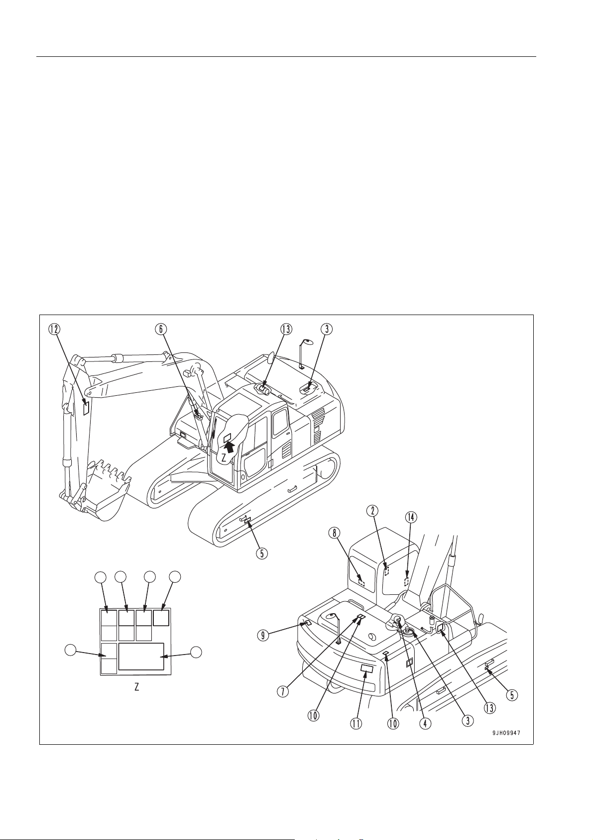
SAFETY LABELS SAFETY
SAFETY LABELS 2
The following warning signs and safety labels are used on this machine.
q Be sure that you fully understand the correct position and content of labels.
q To ensure that the content of labels can be read properly, be sure that they are in the correct place and always
keep them clean. When cleaning them, do not use organic solvents or gasoline. These may cause the labels
to peel off.
q There are also other labels in addition to the warning signs and safety labels. Handle those labels in the same
way.
q If the labels are damaged, lost, or cannot be read properly, replace them with new ones. For details of the p art
numbers for the labels, see this manual or the actual label, and place an order with Komatsu distributor.
LOCATION OF SAFETY LABELS 2
2-4
e
c
b
a
d
f
A
Page 31

SAFETY SAFETY LABELS
SAFETY LABELS
1. (207-00-K1951)
q Warnings for operation, inspe ction and maintenance
q Improper operation and maintenance can cause serious
injury or death.
q Read the manual and labels before operation and mainte-
nance.
Follow instructions and warnings in manual and in labels
on machine.
q Warning!
q Read the manual before operating, maintenance, disas-
sembly, assembly and transportation.
2-5
Page 32

SAFETY LABELS SAFETY
q b. Always apply lock when leaving operator’s seat.
q c. WARNING - No passengers
No passengers allowed to ride on machine while it is moving
q d. WARNING - DANGER OF FALLING OBJECTS
Do not operate where a danger of falling objects exists.
Consult your dealer for fitting of FOPS protection
.
2-6
Page 33

SAFETY SAFETY LABELS
q e. Caution for going close electric cables.
q An electrocution hazard if the ma chine is brought too near
electric power lines
q Keep a safe distance from electric power lines.
q f. Control levers operational function diagram.
WARNING
In order to prevent an accident resulting in injury or death
caused by error-operation, confirm the machine motion
and indicated operating pattern, when operating
machines. Pay attention to the circumference and operate
slowly when confirming the machine motion.
2-7
Page 34

SAFETY LABELS SAFETY
WARNING
To open or close the front or ceiling windows, never stand
up from the operator’s seat before throwing the safe ty lock
lever to the LOCK position.
Inadvertently touching any of the working equipment control levers might cause the machine to start moving all of a
sudden, probably resulting in a serious injury.
2. Caution when stowing front window (09083-A0481)
q Sign indicates a hazard from falling window.
q After raising window, be sure to lock it in place with lock
pins.
(09653-A0481)
q Never remove the cap when the engine is at operating
(high) temperature. Steam or high temperature oil blowing
up from the radiator or hydraulic tank, will cause personal
injury and/or burns.
q Never remove the radiator cap or hydraulic tank oil filler
when cooling water or hydraulic oil is at high temperature.
(3. Caution for high-temperature coolant and hydraulic oil
2-8
Page 35

SAFETY SAFETY LABELS
4. Caution when handling accumulator (09659-A057B)
q There is the hazard of explosion causing injury.
q Do not disassemble the accumulator, make holes in it, weld
it cut it, hit it, roll it or bring it near flame.
5. Caution when adjusting track tension (09657-A0881)
q Sign indicates a hazard of flying plug from tra ck adjuster
that could cause injury.
q Read manual and adjusting track for safe and proper han-
dling.
6. Caution when handling cable (09808- A0881)
q Sign indicates an electric hazard from handling the cable.
q Read manual for safe and proper handling.
7. Stopping rotation for inspection and maintenance
(09667-A0481)
q Sign indicates a hazard of rotating parts, such as belt.
q Turn off before inspection and maintenance.
2-9
Page 36

SAFETY LABELS SAFETY
8. Emergency escape (09844-00050)
9. Caution against falling (09805-A0881)
q There is the hazard of falling down.
q Do not go close to the edge of the machine by mistake.
10. Caution against falling (09805-C0481)
q Sign indicates a hazard of falling.
q Do not stand on this place here.
2-10
Page 37

SAFETY SAFETY LABELS
11. Prohibited to enter swing radius (20E-00-K1150)
q There is danger of getting caught when upper structure
swings.
q Do not enter range of swing
12. Keeping out of working range area (20E-00-K1140)
q Sign indicates a hazard of bei ng hit by the working device
of the machine.
q Keep away from the machine during operation.
13. Prohibition of jump start (09842-A0481)
q Start the engine only after sitting down in the operator’s
seat.
q Do not attempt to start the engine by short-circuiting the
engine starting circuit. Such an act may cause a serious
bodily injury or fire.
14. Caution for use of hydraulic quick coupler piping system
(20J-00-11271)
q There is a danger of an exposed person being killed by fall-
ing attachment.
Read the manual for safe operation.
2-11
Page 38

SAFETY INFORMATION SAFETY
SAFETY INFORMATION 2
SAFETY RULES 2
q Only trained and authorized personnel can operate and maintain the machine.
q Follow all safety rules, precautions and instructions when operating or performing maintenance on the
machine.
q If you are under the influence of alcohol or medication, your ability to safely operate or repair your machine
may be severly impaired putting yourself and everyone else on your jobsite in danger.
q When working with another operator or with a person on worksite traffic duty, be sure that all personnel under-
stand all hand signals that are to be used.
IF PROBLEMS ARE FOUND 2
If you find any problems in the machine during operation o r maintenance (noi se, vibration, smell, incor rect gauges,
smoke, oil leakage, etc., or any abnormal display on the warning devices or monitor), report to the person in
charge and have the necessary action taken. Do not operate the machine until the problem has been corrected.
WORKING WEAR AND PERSONAL PROTECTIVE ITEMS 2
q Do not wear loose clothing and accessories. There is a
hazard that they may catch on control lever s or other protruding parts.
q If you have long hair and it hangs out from your hard hat,
there is a hazard that it may get caught up in the machine,
so tie your hair up and be careful not to let it get caught.
q Always wear a hard hat and safety shoes. If the nature of
the work requires it, wear safety glasses, mask, gloves, ear
plugs, and safety belt when operating or maintaining the
machine.
q Check that all protective equipment functions properly
before using it.
FIRE EXTINGUISHER AND FIRST AID KIT 2
(If equipped)
Always follow the precautions below to prepare for action if any injury or fire should occur.
q Be sure that fire extinguishers have been provided and
read the labels to ensure that you know how to use them in
emergencies.
q Carry out periodic inspection and maintenance to ensure
that the fire extinguisher can always be used.
q Provide a first aid kit in the storage point. Carry out peri-
odic checks and add to the contents if necessary.
2-12
Page 39

SAFETY SAFETY INFORMATION
SAFETY EQUIPMENT 2
q Be sure that all guards and covers are in their proper position. Have gu ards and cover s rep aired immedi ately if
they are damaged.
q Understand the method of use of safety features and use them properly.
q Never remove any safety features. Always keep them in good operating condition.
KEEP MACHINE CLEAN 2
q If water gets into the electrical system, there is a hazard
that it will cause malfunctions or misoperation. Do not use
water or steam to wash the electrical system (sensors,
connectors).
q If inspection and maintenance is carried out when the
machine is still dirty with mud or oil, there is a hazard that
you will slip and fall, or that dirt or mud will get into your
eyes. Always keep the machine clean.
KEEP OPERATOR'S COMPARTMENT CLEAN 2
q When entering the operator's compartment, always remove all mud and oil from the soles of your shoes.
If you operate the pedal with mud or oil affixed to your shoes, your fo ot ma y slip an d t his m a y ca us e a ser iou s
accident.
q Do not leave parts or tools lying around the operator's compartment.
q Do not stick suction pads to the window glass. Suction pads act as a lens and may cause fire.
q Do not use cellular telephones inside the operator's compartment when driving or operating the machine.
q Never bring any dangerous objects such as flammable or explosive items into the operator's compartment.
LEAVING OPERATOR'S SEAT WITH LOCK 2
q Before standing up from the operator's seat (such as when
opening or closing the front window or roof window, or
when removing or installing the bottom window, or when
adjusting the operator's seat), always lower the work
equipment completely to the ground, set lock lever (1)
securely to the LOCK position (L), then stop the engine. If
you accidentally touch the control levers (pedals) when
they are not locked, there is a hazard that the machine may
suddenly move and cause serious injury or property damage.
2-13
Page 40

SAFETY INFORMATION SAFETY
q When leaving the machine, always lower the work equip-
ment completely to the ground, set lock lever (1) securely
to the LOCK position (L), then stop the engine. Use the key
to lock all the equipment. Always remove the key, take it
with you, and keep it in the specified place.
HANDRAILS AND STEPS 2
To prevent personal injury caused by slipping or falling off the machine, always do as follows.
q Use the handrails and steps marked by arrows in the dia-
gram on the right when getting on or off the machine.
q To ensure safety, always face the machine and maintain
three-point contact (both feet and one hand, or both hands
and one foot) with the handrails and steps (including the
track shoe) to ensure that you support yourself.
q Do not grip the control levers or lock lever when getting on
or off the machine.
q Never climb on the engine hood or covers where there are
no non-slip pads.
q Before getting on or off the machine, check the handrails
and steps (including the track shoe). If there is any oil,
grease, or mud on the handrails or steps (including the
track shoe), wipe it off immediately. Always keep these
parts clean. Repair any damage and tighten any loose
bolts.
q Do not get on or off the machine while holding tools in your hand.
2-14
Page 41

SAFETY SAFETY INFORMATION
MOUNTING AND DISMOUNTING 2
q Never jump on or off the machine. Never get on or off a moving machine.
q If the machine starts to mo ve when there is no operator on the machine , do not jump on to the machine a nd try
to stop it.
NO PERSONS ON ATTACHMENTS 2
Never let anyone ride on the work equipment, or other att achments. There is a hazard of falling and suffering serious injury.
DO NOT GET CAUGHT IN ARTICULATED PORTION 2
The clearance around the work equipment will change according to the movement of the link. If you get caught,
this may lead to serious personal injury. Do not allow anyone to approach any rotating or telescoping part.
BURN PREVENTION 2
Hot coolant
q To prevent burns from hot water or steam spurting out
when checking or draining the coolant, wait for the water to
cool to a temperature where it is pos sib le to to uc h th e ra diator cap by hand before starting the operation. Even when
the coolant has cooled down, loosen the cap slowly to
relieve the pressure inside the radiator before removing the
cap.
Hot oil
q To prevent burns from hot oil spurting out when checking or
draining the oil, wait for the oil to cool to a temperature
where it is possible to touch the cap or plug by hand before
starting the operation. Even when the oil has cooled down,
loosen the cap or plug slowly to relieve the internal pressure before removing the cap or plug.
2-15
Page 42

SAFETY INFORMATION SAFETY
FIRE PREVENTION AND EXPLOSION PREVENTION
q Fire caused by fuel or oil
Fuel, oil, antifreeze, and window washer liquid are particularly flammable and can be hazardous. To prevent fire,
always observe the following:
Q Do not smoke or use any flame near fuel or oil.
Q Stop the engine be fore refueling.
Q Do not leave the machine while adding fuel or oil.
Q Tighten all fuel and oil caps securely.
Q Do not spill fuel on overheated surfaces or on parts of
the electrical system.
Q Use well-ventilated areas for adding or storing oil and
fuel.
Q Keep oil and fuel in the determined place and do not
allow unauthorized persons to enter.
Q After adding fuel or oil, wipe up any spilled fuel or oil.
Q When carrying out grinding or welding work on the
chassis, move any flammable materials to a safe plac e
before starting.
Q When washing parts with oil, use a non-flamm able oil. Diesel oil and gasoline may catch fire, so do not
use them.
Q Put greasy rags and other flammable materials into a safe container to maintain safety at the work place.
Q Do not weld or use a cutting torch to cut any pipes or tubes that contain flammable liquids.
q Fire caused by accumulation of flammable material.
Remove any dry leaves, chips, pieces of paper, dust, or any other flammable materials accumulated or affixed
around the engine, exhaust manifold, muffler, or battery, or inside the undercovers.
q Fire coming from electric wiring
Short circuits in the electrical system can cause fire.
Q Always keep electric wiring connections clean and securely tightened.
Q Check the wiring every day for looseness or damage. Tighten any loose connectors or wiring clamps.
Repair or replace any damaged wiring.
q Fire coming from hydraulic line.
Check that all the hose and tube clamps, guards, and cushions are securely fixed in position.
If they are loose, they may vibrate during operation and rub against other parts. This may lead to damage to
the hoses, and cause high-pressure oil to spurt out, leading to fire damage or serious injury.
q Explosion caused by lighting equipment
Q When checking fuel, oil, battery electrolyte, window washer fluid, or coolant, always use lighting with anti-
explosion specifications. If such lighting equipment is not used, there is danger of explosion that may
cause serious injury.
Q When taking the electrical power for the lighting from th e machine it se lf, follow the instructions in this man-
ual.
2-16
Page 43

SAFETY SAFETY INFORMATION
ACTION IF FIRE OCCURS 2
If a fire occurs, escape from the machine as follows.
q Turn the start switch OFF to stop the engine.
q Use the handrails and steps to get off the machine.
WINDSHIELD WASHER FLUID 2
Use an ethyl alcohol base washer liquid.
Methyl alcohol base washer liquid may irritate your eyes, so do not use it.
FALLING OBJECTS, FLYING OBJECTS AND INTRUDING OBJECTS PREVENTION 2
On jobsites where there is a hazard that falling objects, flying
objects, or intruding objects may hit or e nter the oper ator 's cab,
consider the operating conditions and install the nece ssary
guards to protect the operator.
q When carrying out demolition or breaker operations, install
a front guard and use a laminated coating sheet on the
front glass.
q When working in mines or quarries where there is a hazard
of falling rock, install FOPS (Falling Objects Protective
Structure) and a front guard, and use a laminated coating
sheet on the front glass.
q When carrying out the above operations, always close the
front window. In addition, always ensure that by standers
are a safe distance away and are not in hazard from falling
or flying objects.
q The above recommendations assume that the conditions
are for standard operations, but it may be necessary to add
additional guards according to the operating conditions on
the jobsite. Always contact your Komatsu distributor for
advice.
ATTACHMENT INSTALLATION 2
q When installing optional parts or attachments, there may be problems with safety or legal restrictions. There-
fore contact your Komatsu distributor for advice.
q Any injuries, accidents, or product failures resulting from the use of unauthorized attachments or parts will not
be the responsibility of Komatsu.
q When installing and using optional attachments, read the instruction manual for the attachment, and the gen-
eral information related to attachments in this manual.
2-17
Page 44

SAFETY INFORMATION SAFETY
ATT A CHMENT COMBINATIONS 2
Depending on the type or combination of work equipment, there is a hazard that the work equipment may hit the
cab or other parts of the machine. Before using unfamiliar work equipment, check if there is any hazard of interference, and operate with caution.
CAB WINDOW GLASSES 2
q If the cab glass on the work equipment side is broken, there is a hazard that the work equipment may contact
the operator's body directly. Stop operation immediately and replace the glass.
q The ceiling window is made of organic glass (polycarbonate), and as such it is apt to break easily when receiv-
ing damage on the surface, thereby deteriorating its protective characteristic. If there is a crack or damage
caused by a fallen rock, or when any sign of them is noticed, replace it with a new window.
UNAUTHORIZED MODIFICATIONS 2
If this machine is modified without permission from Komatsu, there is danger that problems may occur with safety
and that this may lead to serious personal injury. Modifications may have an adverse effect on items such as
machine strength and visibility. Before making any modifications, please consult your Komatsu distributor.
Komatsu cannot take any responsibility for accidents, failures, or damage caused by modifications not authorized
by Komatsu.
SAFETY AT JOBSITE 2
Before starting operations, thoroughly check the area for any unusual conditions that could be dangerous.
q When carrying out operations near combustible materials such as thatched roofs, dry leaves or dry grass,
there is a hazard of fire, so be careful when operating.
q Check the terrain and condition of the ground at the worksite, and determine the safest method of operation.
Do not operate where there is a hazard of landslides or falling rocks.
q If water lines, gas lines, or high-voltage electrical lines may
be buried under the worksite, contact each utility and identify their locations. Be careful not to sever or damage any
of these lines.
q Take action to prevent unauthorized people from approach-
ing the jobsite.
When working on public roads, position flagmen and erect
barriers to ensure the safety of passing traffic and pedestrians.
q When traveling or operating in shallow water or on soft
ground, check the shape and condition of the bedrock, and
the depth and speed of flow of the water before starting
operations.
WORKING ON LOOSE GROUND 2
q Avoid traveling or operating your machine too close to the edge of cliffs, overhangs, and deep ditches. The
ground may be weak in such areas. If the ground should collapse under the weight or vibra tion of the machine,
there is a hazard that the machine may fall or tip over. Remember that the soil after heavy rain or blasting or
after earthquakes is weak in these areas.
2-18
Page 45

SAFETY SAFETY INFORMATION
q When working on embankments or near excavated ditches, there is a hazard that the weight and vibration of
the machine will cause the soil to collapse. Before starting operations, take steps to ensure that the ground is
safe and to prevent the machine from rolling over or falling.
DISTANCE TO HIGH VOLTAGE CABLES 2
Do not travel or operate the machine near electric cables.
There is a hazard of electric shock, which may cause serious
injury or property damage. On jobsites where the machine may
go close to electric cables, always do as follows.
q Before starting work near electric cables, inform the local
power company of the work to be performed, and ask them
to take the necessary action.
q Even going close to high-voltage cables can cause electric
shock, which may cause serious burns or even death.
Always maintain a safe distance (see the t able o n the right)
between the machine and the electric cable. Check with
the local power company about safe operating procedure
before starting operations.
q To prepare for any possible emergencies, wear rubber
shoes and gloves. Lay a rubber sheet on top of the seat,
and be careful not to touch the chassis with any exposed
part of your body.
q Use a signalman to give warning if the machine
approaches too close to the electric cables.
Low voltage
Very high
voltage
Voltage
100 V - 200 V 2 m
6,600 V 2 m
22,000 V 3 m
66,000 V 4 m
154,000 V 5 m
187,000 V 6 m
275,000 V 7 m
500,000 V 11 m
Min.safety
distance
q When carrying out operations near high voltage cables, do not let anyone near the machine.
q If the machine should come too close or touch the electric cable , to prevent electric sh ock, the operato r should
not leave the operator's compartment until it has been confirmed that the electricity has been shut off.
Also, do not let anyone near the machine.
ENSURE GOOD VISIBILITY 2
This machine is equipped with mirrors to improve the visibility, but even with mirrors, there are places, which cannot be seen from the operator's seat, so always be careful when operating.
When operating or traveling in places with poor visibility , if it is impossible to confirm the condition of the job side or
obstacle is in the area around the machine, there is danger that the machine may suffer damage or the operator
may suffer serious personal injury. When operating or traveling in places with poor visibility, always observe the
following items strictly.
q If the visibility cannot be sufficiently assured, position a flagman if necessary. The oper ator should pay careful
attention to the signs and follow the instructions of the flagman.
q The signals should be given only by one flagman.
q When working in dark places, turn on the working lamps and front lamps of the machine, and if necessary, set
up additional lighting in the area.
q Stop operations if there is poor visibility, such as in fog, snow, rain, or sand storms.
2-19
Page 46

SAFETY INFORMATION SAFETY
q Check the mirrors on the machine before starting operations every day. Clean off any dirt and adjust the view
to ensure good visibility.
q In areas where it is impossible to confirm the area behind the machine and observation cameras have been
set up, clean off any dirt from the lens and make sure that the camera gives a clear view of the rear.
VENTILATION FOR ENCLOSED AREA 2
Exhaust fumes from the engine can kill.
If it is necessary to start the engine within an enclosed area, or
when handling fuel, flushing oil, or paint, open the doors and
windows to ensure that adequate ventilation is provided to prevent gas poisoning.
SIGNALMAN'S SIGNAL AND SIGNS 2
q Set up signs to inform of road shoulders and soft ground. If the visibility is not good, position a signalman if
necessary. Operators should pay careful attention to the signs and follow the instructions from the signalman.
q Only one signalman should give signals.
q Make sure that all workers understand the meaning of all signals and signs before starting work.
EMERGENCY EXIT FROM OPERATOR'S CAB 2
q If it should be impossible to open the door of the cab, break the window glass with the hammer supplied and
use the window as an emergency escape.
For details, see “EMERGENCY ESCAPE HAMMER (3-82)“ in this volume.
q To prevent injury, remove the broken pieces of glass remaining in the frame before escaping through the win-
dow. Be careful also not to slip on the broken pieces of glass.
ELECTROMAGNETIC INTERFERENCE 2
When this machine is operating close to a source of high electromagnetic interference, such as a radar station,
some abnormal phenomena may be observed.
q The display on the monitor panel may behave erratically
q The warning buzzer may sound.
These effects do not signify a malfunction and the machine will return to normal as soon the source of interference
is removed.
2-20
Page 47

SAFETY SAFETY INFORMATION
ASBESTOS DUST HAZARD PREVENTION 2
Asbestos dust in the air can cause lung cancer if it is inhaled.
There is danger of inhaling asbestos when working on jobsites
handling demolition work or work handling industrial waste.
Always observe the following.
q Spray water to keep down the dust when cleaning. Do not
use compressed air for cleaning.
q If there is danger that there may be asbestos dust in the
air, always operate the machine from an upwind position.
All workers should use an approved respirator.
q Do not allow other persons to approach during the opera-
tion.
q Always observe the rules and regulations for the work site
and environmental standards.
This machine does not use asbestos, but there is a danger that imitation parts may contain asbestos, so always
use genuine Komatsu parts.
2-21
Page 48

SAFETY MACHINE OPERATION SAFETY
SAFETY MACHINE OPERATION 2
STARTING ENGINE 2
If there is a warning tag hanging from the work equipment control lever, do not start the engine or touch the levers .
CHECKS BEFORE STARTING ENGINE 2
Carry out the following checks before starting the engine at the beginning of the day's work.
q Remove all dirt from the surface of the window glass to ensure a good view.
q Remove all dirt from the surface of the lens of the front lamps and working lamps, and check that they light up
correctly.
q Check the coolant level, fuel level, and oil level in engine oil pan, check for clogging of the air cleaner, and
check for damage to the electric wiring.
q Adjust the operator's seat to a position where it is easy to carry out operations, and check that there is no dam-
age or wear to the seat belt or mounting clamps.
q Check the operation of the instruments and gauges, check the angle of the mirror, an d check that the contro l
levers are all at the Neutral position.
q Before starting the engine, check that lock lever (1) is in
LOCK position (L).
q Adjust the mirrors so that the rear of the machine can be
seen clearly from the operator's seat.
When adjusting, see “Rearview Mirrors (3-119)“.
q Check that there are no persons or obstacles above,
below, or in the area around the machine.
2-22
Page 49

SAFETY SAFETY MACHINE OPERATION
SAFETY RULES FOR STARTING ENGINE 2
q When starting the engine, sound the horn as a warning.
q Start and operate the machine only while seated.
q Do not allow anyone apart from the operator to ride on the machine.
q Do not short-circuit the starting motor circuit to start the engine. It is not only dangerous, but may also cause
serious personal injury or fire.
STARTING ENGINE IN COLD WEATHER 2
q Carry out the warming-up operation thoroughly. If the machine is not thoroughly warmed up before the control
levers (pedals) are operated, the reaction of the machine will be slow or the machine may move in a way not
expected by the operator. Particularly in cold weather, be sure to carry out the warming-up operatio n thoroughly.
q If the battery electrolyte is frozen, do not charge the battery or start the engine with a different power source.
There is a hazard that this will ignite the battery and cause the battery to explode.
Before charging or starting the engine with a dif ferent p ower source, melt the battery el ectrolyte and check that
there is no leakage of electrolyte before starting.
2-23
Page 50

SAFETY MACHINE OPERATION SAFETY
OPERATION 2
CHECKS BEFORE OPERATION 2
When carrying out the checks, move the machine to a wide area where there are no obstructions, and operate
slowly. Do not allow an yone near the machine.
q Always fasten your seat belt.
q Check that the movement of the machine matches the display on the control pattern card. If it does not match,
replace it immediately with the correct control pattern card.
q Check the operation of the gauges and equipment, and check the operation of the bucket , arm, boom, travel
system, swing system, and steering system.
q Check for any problem in the sound of the m achine, vibrat ion, heat, smell, or gauges; check also that there is
no leakage of oil or fuel.
q If any problem is found, carry out repairs immediately.
SAFETY RULES FOR CHANGING MACHINE DIRECTIONS 2
q Before traveling, set the machine so that sprocket (1) is
behind the operator's seat.
If sprocket (1) is in front of the operator's cab, the machine
moves in the opposite direction from the operation of the
lever (front and rear travel is reversed, left and right steering is reversed). Be extremely careful when operating the
machine in this situation.
q Before travelling, check again that there is no one in the
surrounding area, and that there are no obstacles.
q Before travelling, sound the horn to warn people in the
area.
q Always operate the machine only when seated.
q Do not allow anyone apart from the operator to ride on the
machine.
q Check that the travel alarm (if equipped) works properly.
q Always lock the door and window s of the operator's com-
partment in position (open or closed).
On jobsites where there is a hazard of flying objects or of
objects entering the operator's compartment, check that
the door and windows are securely closed.
q If there is an area to the rear of the machine which cannot
be seen, position a signal person. Take special care not to
hit other machines or people when turning or swinging the
machine.
Always be sure to carry out the above precautions even when
the machine is equipped with mirrors.
2-24
Page 51

SAFETY SAFETY MACHINE OPERATION
SAFETY RULES FOR TRAVELLING 2
q When traveling on flat ground, keep the work equipment 40
to 50 cm high above the ground.
q If the view to the right side is poor, raise the boom to
ensure better visibility.
q When travelling on rough grou nd, travel at low speed and
do not operate the steering suddenly. There is danger that
the machine may turn over. The work equipment may hit
the ground surface and cause the machine to lose its balance, or may damage the machine or structures in the
area.
q When travelling on rough ground or steep slopes, if the
machine is equipped with auto-deceleration, always turn
the auto-deceleration switch OFF (cancel).
q Avoid travelling over obstacles when possible. If the
machine has to travel over an obstacle, keep the work
equipment close to the ground and travel at low speed.
Never travel over obstacles which make the machine tilt
strongly to one side.
q When travelling or carrying out operations, always keep a
safe distance from people, structures, or other machines to
avoid coming into contact with them.
q When passing over bridges or structures, check first that
the structure is strong enough to support the weight of the
machine. When traveling on public roads, check first with
the relevant authorities and follow their instructions.
q When operating in tunnels, under bridge s, under electric wires, or other places where the height is limited,
operate slowly and be extremely careful not to let the work equipment hit anything.
2-25
Page 52

SAFETY MACHINE OPERATION SAFETY
TRAVELLING ON SLOPES 2
To prevent the machine from tipping over or slipping to the
side, always do as follows.
q Keep the work equipment approx. 20 to 30 cm above the
ground. In case of emergency , lower the work equipment to
the ground immediately to help stop the machine.
q When travel up slopes, set the operator's cab facing uphill,
when travel down slopes, set the operator's cab facing
downhill. Always check the firmness of the ground under
the front of the machine when traveling.
q When travelling up a steep slope, extend the work equip-
ment to the front to improve the balance, keep the work
equipment approximately 20 to 30 cm above the ground,
and travel at low speed.
q When travelling downhill, lower the engine speed, keep the
travel lever close to the neutral position, and travel at low
speed.
q Always travel straight up or down a slope. Traveling at an
angle or across the slope is extremely dangerous.
q Do not turn on slopes or travel across slopes. Always go
down to a flat place to change the position of the machine,
then travel on to the slope again.
q Travel on grass, fallen leaves, or wet steel plates with low
speed. Even with slight slopes there is a hazard that the
machine may slip.
2-26
Page 53

SAFETY SAFETY MACHINE OPERATION
OPERATIONS ON SLOPES 2
q When working on slopes, there is a hazard that the machine may lose its balance and turn over when the
swing or work equipment are operated. Thi s may le ad to seri ous inju ry o r pr ope rty damag e, so always pr ovide
a stable place when carrying out these operations, and operate carefully.
q Do not swing the work equipment from the uphill side to the
downhill side when the bucket is loaded. This operation is
dangerous, and may cause the machine to tip over.
q If the machine has to be used on a slope, pile the soil to
make a platform (A) that will keep the machine as horizontal as possible.
PROHIBITED OPERATIONS 2
q Never dig the work face under an overhang. There is a
hazard that rocks may fall or that the overhang may collapse and fall on top of the machine.
q Do not excavate too deeply under the front of the machine.
The ground under the machine may collapse and cause
the machine to fall.
q To make it easier to escape if there is any problem, set the
tracks at right angles to the road shoulder or cliff with the
sprocket at the rear when carrying out operations.
2-27
Page 54

SAFETY MACHINE OPERATION SAFETY
q Do not carry out demolition work under the machine. There
is a hazard that the machine may become unstable and tip
over.
q When working on or from the top of buildings or other
structures, check the strength and the structure before
starting operations. There is a hazard of the building collapsing and causing serious injury or damage.
q When carrying out demolition work, do not carry out demo-
lition above your head. There is a hazard of broken parts
falling or of the building collapsing and causing serious
injury or property damage.
q Do not use the impact force of the work equipment for
breaking work. There is a hazard of damage to the work
equipment, or a hazard of serious personal injury being
caused by flying pieces of broken materials, or of the
machine tipping over due to reaction from the impact.
q Generally speaking, the machine is more liable to overturn
when the work equipment is at the side than when it is at
the front or rear.
q When using a breaker or other heavy work equipment,
there is a hazard of the machine losing its balance and tipping over. When operating on flat ground as well as on
slopes.
Q Do not suddenly lower, swing, or stop the work equipment.
Q Do not suddenly extend or retract the boom cylinder. There is a hazard that impact will cause the machine
to tip over.
q Do not pass the bucket over the head of other workers or over the operator's seat of dump trucks or other
hauling equipment. The load may spill or the bucket may hit the dump truck and cause serious injury or property damage.
2-28
Page 55

SAFETY SAFETY MACHINE OPERATION
OPERATIONS ON SNOW 2
q Snow-covered or frozen surfaces are slippery, so be extremely careful when traveling or operating the
machine, and do not operate the levers suddenly. Even a slight slope may cause the machine to slip, so be
particularly careful when working on slopes.
q With frozen ground surfaces, the ground becomes soft when the temperature rises, and this may cause the
machine to tip over.
q If the machine enters deep snow, the re is a hazard that it may tip over or be come bu rie d in the sn ow. Be care-
ful not to leave the road shoulder or to get trapped in a snow drift.
q When clearing snow, the road shoulder and objects placed beside the road ar e buried in the snow and cannot
be seen. There is a hazard of the machine tipping over or hitting covered objects, so always carry out operations carefully.
PARKING MACHINE 2
q Park the machine on firm, level ground.
q Select a place where there is no hazard of falling rocks or
landslides, or of flooding if the land is low.
q Lower the work equipment completely to the ground.
q When leaving the machine, set lock lever (1) to the LOCK
position (L), then stop the engine.
q Always close the operator's cab door, and use the key to
lock all the equipment in order to prevent any unauthor ized
person from moving the ma chine . Alwa ys rem ove the key,
take it with you, and leave it in the specified place.
q If it is necessary to park the machine on a slope, a lwa ys do
as follows.
Q Set the bucket on the downhill side, then dig it into the
ground.
Q Put blocks under the tracks to prevent the machine
from moving.
2-29
Page 56

SAFETY MACHINE OPERATION SAFETY
TRANSPORTATION 2
The machine can be divided into parts for transpo rtation, so when transportating the machine, please contact your
Komatsu distributor to have the work carried out.
LOADING AND UNLOADING 2
When loading or unloading the machine, mistaken operation
may bring the hazard of the machine tipping over or falling, so
particular care is necessary. Always do as follows.
q Perform loading and unloading on firm, level ground only.
Maintain a safe distance from the edge of the road or cliff.
q Never use the work equipment to load or unload the
machine. There is danger that the machine may fall or tip
over.
q Always use ramps of adequate strength. Be sure that the
ramps are wide, long, and thick enough to provide a safe
loading slope. Take suitable steps to prevent the ramps
from moving out of position or coming off.
q Be sure the ramp surface is clean and free of grease, oil, ice and loose materials. Remove dirt from machine-
tracks. On a rainy day, in particular, be extremely careful since the ramp surface is slippery.
q Turn the auto-decelerator switch OFF (auto-deceleration function released).
q Run the engine at low speed and travel slowly.
q When on the ramps, do not operate any lever except for the travel lever.
q Never correct your steering on the ramps. If necess ary, drive off the ramps, correct the direction, then enter
the ramps again.
q The center of gravity of the machine will change suddenly at the joint between the ramps and the track or
trailer, and there is danger of the machine losing its balance. Travel slowly over this point.
q When loading or unloading to an emb ankment or platform, make sure th at it has suitable width, streng th, and
grade.
q When swinging the upper structure on the trailer, the trailer is unstable, so pull in the work equipment and
swing slowly.
q For machines equipped with a ca b, always lock the door after boarding th e machine. If this is not done, the
door may suddenly open during transportation.
Refer to “TRANSPORTATION (3-164)“.
REMARK
Explanation of diagram on right: (1) Blocks (2) Ramp (a) Center line of trailer (4) Angle for setting ramps
(Max. 15°)
2-30
Page 57

SAFETY SAFETY MACHINE OPERATION
SHIPPING THE MACHINE 2
When shipping the machine on a trailer, do as follows.
q The weight, transportation height, and overa ll length of the machine differ according to the work equipment, so
be sure to confirm the dimensions.
q When passing over bridges or structures on pr ivate land , check first that the structure is strong enough to sup-
port the weight of the machine. When traveling on public roads, check first with the relevant auth orities and follow their instructions.
q For details of the shipping procedure, see “TRANSPORTATION (3-164)“ in the OPERATION section.
2-31
Page 58

SAFETY MACHINE OPERATION SAFETY
BATTERY 2
BATTERY HAZARD PREVENTION
Battery electrolyte contains sulphuric acid, and batteries generate flammable hydrogen gas, which may explode.
Mistaken handling can lead to serious injury or fire. For this reason, always observe the following precautions.
q Do not use or charge the battery if the battery electrolyte level is below the LOWER LEVEL line. This may
cause an explosion. Check the battery electrolyte level periodically and add distilled water to bring the electrolyte level to the UPPER LEVEL line.
q When working with batteries, always wear safety glasses
and rubber gloves.
q Never smoke or use any flame near the batter y.
q If you spill acid on your clothes or skin, immediately flush
the area with large amount of water.
q If acid gets into your eyes, flush them immediately with
large amount of water and seek medical attention.
q Before working with batteries, turn the starting switch to the
OFF position.
As there is a hazard that sparks will be generated, always do as follows.
q Do not let tools or other metal objects make any contact between the battery terminals. Do not leave tools or
other metal objects lying around near th e battery.
q Always disconnect the negative (-) terminal (ground side) first when removing the battery; when installing the
battery, connect the positive (+) terminal first, and connect the grou nd last. Tighten the battery terminals
securely.
q Flammable hydrogen gas is generated when the battery is charged, so remove the battery from the chassis,
take it to a well-ventilated place, and remove the battery caps before char gin g it.
q Tighten the battery caps securely.
q Install the battery securely to the determined place.
2-32
Page 59

SAFETY SAFETY MACHINE OPERATION
STARTING ENGINE WITH BOOSTER CABLES 2
If any mistake is made in the method of connecting the booster
cables, it may cause the battery to explode, so always do as
follows.
q When starting with a booster cable, carry out the starting
operation with two workers (one worker sitting in the operator's seat and the other working with the battery).
q When starting from another machine, do not allow the two
machines to touch.
q When connecting the booster cables, turn the starting
switch OFF position for both the normal machine and problem machine. There is a hazard that the machine will move
when the power is connected.
q Be sure to connect the positive (+) cable first when install-
ing the booster cables. Disconnect the negative (-) cable
(ground side) first when removing them.
q When removing the booster cables, be careful not to let the
booster cable clips touch each other or to let the clips touch
the machine.
q Always wear safety goggles and rubber gloves when start-
ing the engine with booster cables.
q When connecting a normal machine to a problem machine
with booster cables, always use a normal machine with the
same battery voltage as the problem machine.
q For details of the starting procedure when using booster cables, see “Starting Engine with Booster Cables (3-
188)“ in the OPERAT ION section.
2-33
Page 60

SAFETY MACHINE OPERATION SAFETY
TOWING 2
SAFETY RULES FOR TOWING 2
Serious injury or death could result if a disabled machine is towed incorrectly or if there is a mistake in the selection or inspection of the wire rope.
For towing, see “TOWING THE MACHINE (3-184)“.
q Always check that the wire rope used for towing has ample strength for the weight of the machine being
towed.
q Never use a wire rope which has cut strands (A), reduced
diameter (B), or kinks (C). There is danger that the rope
may break during the towing operation.
q Always wear leather gloves when handling wire rope.
q Never tow a machine on a slope.
q During the towing operation, never stand between the tow-
ing machine and the machine being towed.
q Operate the machine slowly and be careful not to apply
any sudden load to the wire rope.
2-34
Page 61

SAFETY SAFETY MACHINE OPERATION
LIFTING OBJECTS WITH BUCKET 2
SAFETY RULES FOR LIFTING OBJECTS 2
q Determine the signals to be used and place a signalman in position.
q To prevent the machine from tipping over or falling, carry out the operation on flat ground.
q To prevent the danger of contact with a raised load or the danger from a falling load, do not allow any worker
inside the area.
q Do not exceed the specified lifting load.
For details of the maximum lifting load permitted for this machine, see “BUCKET WITH HOOK (6-7)“.
q It is dangerous if the raised load hits any person or structure. When swinging or operating the work equip-
ment, check carefully that the surrounding area is safe.
q Do not swing or operate the work equipment suddenly. There is danger that this may cause the load to sway
and the machine to tip over.
q Do not leave the operator's seat when there is a raised load.
q Do not use the work equipment or swing to pull the load in
any direction. There is danger that the hook may break and
the load come off, causing the work equipm ent to move
suddenly and cause personal injury.
2-35
Page 62

SAFETY MAINTENANCE INFORMATION SAFETY
SAFETY MAINTENANCE INFORMATION 2
WARNING TAG 2
q Always attach the “DO NOT OPERATE“ warning tag to the
work equipment control lever in the operator's cab to alert
others that you are performing service or maintenance on
the machine. Attach additional warning tags around the
machine if necessary.
Warning tag Part No. 09963-A1640
Keep this warning tag in the tool box while it is not used. If
there is not the tool box, keep the tag in the operation m anual pocket.
q If any other person starts the engine , or touches or oper-
ates the work equipment control levers (pedals) while you
are performing service or maintenance, you may suffer
serious injury.
KEEP WORK PLACE CLEAN AND TIDY 2
q Do not leave hammers or other tools lying around in the work place. Wipe up all grease, oil, or other sub-
stances that will cause you to slip. Always keep the work place clean and tidy to enable you to carry out operations safely.
If the work place is not kept claen and tidy , there is the danger that you will trip, slip, or fall over and injure yourself.
q When cleaning the ceiling window which is made of organic glass (polycarbonate), use tap water and avoid
use of organic solvents for cleaning. An organic solvent like benzene, toluene or methanol can invite a chemical reaction like dissolution and decomposition on the window glass, deteriorating polycarbonate in use.
APPOINT LEADER WHEN WORKING WITH OTHERS 2
q When repairing the machine or when removing and installing the work equipment, appoint a leader and follow
his instructions during the operation.
2-36
Page 63

SAFETY SAFETY MAINTENANCE INFORMATION
STOP ENGINE BEFORE CARRYING OUT MAINTENANCE 2
q Stop the machine on firm, level ground.
q Select a place where there is no hazard of falling rocks or
landslides, or of flooding if the land is low.
q Lower the work equipment completely to the ground and
stop the engine.
q Turn the starting switch to the ON position. Operate the
work equipment control lever back and forth, left and right
at the full stroke 2 to 3 times to eliminate the remaining
internal pressure in the hydraulic circuit, and then push up
lock lever (1) to the LOCK position (L).
q Put blocks under the track to prevent the machine from
moving.
2-37
Page 64

SAFETY MAINTENANCE INFORMATION SAFETY
TWO WORKERS FOR MAINTENANCE WHEN ENGINE IS RUNNING 2
To prevent injury, do not carry out maintenance with the engine
running. If maintenance must be carried out with the engine
running, carry out the operation with at least two workers and
do as follows.
q One worker must always sit in the operator's seat and be
ready to stop the engine at any time. All workers must
maintain contact with the other workers.
q Set lock lever (1) to the LOCK position (L) to prevent the
work equipment from moving.
q When carrying out operations near the fan, fan belt, or
other rotating parts, there is a hazard of bein g caught in the
parts, so be careful not to come close.
q Do not touch any control levers (pedals). If any control
lever (pedal) must be operated, always give a signal to the
other workers to warn them to move to a safe place.
q Never drop or insert tools or other objects into the fan or
fan belt. Parts may break or be sent flying.
PROPER TOOLS 2
Use only tools suited to the task and be sure to use the tools
correctly. Using damaged, low quality, faulty, makeshift tools or
improper use of the tools could cause serious personal injury.
2-38
Page 65

SAFETY SAFETY MAINTENANCE INFORMATION
ACCUMULATOR 2
The accumulator is charged with high-pressure nitrogen gas.
When handling the accumulator, careless procedure may
cause an explosion which could lead to serious injury or property damage. For this reason, always observe the following
precautions.
q Do not disassemble the accumulator.
q Do not bring it near flame or dispose of it in fire.
q Do not make holes in it, weld it, or use a cutting torch.
q Do not hit or roll the accumulator, or subject it to any
impact.
q When disposing of the accumulator, the gas must be
released. Please contact your Komatsu distributor to have
this work performed.
HANDLING GAS SPRING 2
The gas springs are located at the engine hood (left, right: two places). The diagram below shows the gas spring
on the left side of the engine hood.
Precautions when using
q Never disassemble.
The gas springs are charged with pressurized nitrogen
gas, so it is extremely dangerous to disassemble them.
q Never dispose of them in fire.
The nitrogen gas in the gas springs is not flammable, but if
a gas spring is thrown into fire, the high temperatures will
cause softening and breakage of the seals and rod guide
and when the gas inside the tube expands, there is danger
that it may burst and spray out oil.
q If there is any leakage of oil or gas, stop use immediately
and contact your Komatsu distributor or place of purchase.
If the gas pressure goes down, there is danger that it will
be unable to hold the hood.
2-39
Page 66

SAFETY MAINTENANCE INFORMATION SAFETY
Precautions when discarding
q When disposing of a gas spring, do not throw it into fire.
q Fix the gas spring securely in a horizontal position to a bor-
ing machine.
Drill 2 or 3 mm diameter holes at a position 20 mm to 30
mm from the end face at the tube bracket end to release
the gas before disposing of the gas spring.
When doing this, there is danger that the internal oil, metal
filings, or the internal pressurized gas may cause things to
fly, so always wear safety glasses when carrying out the
operation.
Before disposing of the gas spring, retract the rod and check th at it cannot extend, and check also that the
internal gas has been completely released.
PERSONNEL 2
Only authorized personnel can service and repair the machine. Do n ot allow unauthorized personnel into the
area. If necessary, employ an observer.
ATTACHMENTS 2
q Appoint a leader before starting removal or installation
operations for attachments.
q Place attachments that have been removed from the
machine in a stable condition so that they do not fall. And
take steps to prevent unauthorized persons from entering
the storage area.
WORK UNDER THE MACHINE 2
q If it is necessary to go under the work equipment or the
machine to carry out service and maintenance, support the
work equipment and machine securely with blocks and
stands strong enough to support the weight of the work
equipment and machine.
q It is extremely dangerous to work under the machine if the
track shoes are lifted off the ground and the machine is
supported only with the work equipment. If any of the control levers is touched by accident, or there is damage
occurring to the hydraulic piping, the work equipment or the
machine will suddenly drop. This is extremely dangerous.
Never work under the work equipment or the mac hine.
2-40
Page 67

SAFETY SAFETY MAINTENANCE INFORMATION
NOISE 2
When carrying out maintenance of the engine and you are exposed to noise for lo ng periods of time, wear ear covers or ear plugs while working.
If the noise from the machine is too loud, it may cause temporary or permanent hearing problems.
WHEN USING HAMMER 2
When using a hammer, pins may fly out or metal particles may
be scattered. This may lead to serious injury. Always do as
follows.
q If hard metal parts such as pins, bucket teeth, cutting
edges, or bearings are hit with a hammer, there is a hazard
that pieces might be scattered and cause injury. Always
wear safety goggles and gloves.
q When hitting pins or bucket teeth, there is a hazard that
broken pieces might be sent flying an d injure peop le in the
surrounding area. Always check that there is no one in the
surrounding area.
q There is a hazard that the pin hit with strong force may fly out and injure people in the surrounding area.
WELDING WORKS 2
Welding operations must always be carried out by a qualified welder and in a place equipped with prop er equipment. There is a hazard of gas, fire, or electrocution when carrying out welding, so never allow any unqualified
personnel to carry out welding.
REMOVING BATTERY TERMINALS 2
When repairing the electrical system or when carrying out electrical welding, remove the negative (-) terminal of
the battery to prevent the flow of current.
2-41
Page 68

SAFETY MAINTENANCE INFORMATION SAFETY
SAFETY FIRST WHEN USING HIGH-PRESSURE GREASE TO ADJUST TRACK TENSION 2
q Grease is pumped into the track tension adjustment sys-
tem under high pressure.
If the specified procedure for maintenance is not followed
when making adjustment, grease drain plug (1) may fly out
and cause serious injury or property damage.
q When loosening grease drain plug (1) to loosen the track
tension, never loosen it more than one turn. Loosen the
grease drain plug slowly.
q Never put your face, hands, feet, or any other part of your
body close to grease drain plug (1).
DO NOT DISASSEMBLE RECOIL SPRINGS 2
Never attempt to disassemble the recoils spring assembly. It
contains a spring under high pressure which serves as a shock
absorber for the idler. If it is disassembled by mistake, the
spring will fly out and cause serious injury. When it becomes
necessary to disassemble it, ask your Komatsu distributor to do
the work.
SAFETY RULES FOR HIGH-PRESSURE OIL 2
The hydraulic system is always under internal pressure. When inspecting or replacing piping or hoses, always
check that the pressure in the hydraulic circuit has been released. If the circuit is still under pressure, it will lead to
serious injury, so always do as follows.
q Release the pressure in the hydraulic circuit. For details, see “METHOD OF RELEASING PRESSURE IN
HYDRAULIC CIRCUIT (4-74)“. Do not carry out any inspection or replacement work when the hydraulic system is under pressure.
q If there is any leakage from the piping or hoses, the surrounding area will be wet, so check for cracks in the
piping and hoses and for swelling in the hoses.
When carry out inspection, wear safety glasses and leather gloves.
2-42
Page 69

SAFETY SAFETY MAINTENANCE INFORMATION
q There is a hazard that high-pressure oil leaking from small
holes may penetrate your skin or cause blindness if it contacts your eyes directly. If you are hit by a jet of high-pressure oil and suffer injury to your skin or eyes, wash the
place with clean water, and consult a doctor immediately
for medical attention.
PRECAUTION FOR HIGH FUEL PRESSURE
High pressure is generated inside the engine fuel piping whe n the engine is r unning. When carrying out inspe ction
or maintenance of the fuel piping system, wait for at least 30 seconds after stopping the engine to let the internal
pressure go down before starting inspection or maintenance.
SAFETY HANDLING HIGH-PRESSURE HOSES
q If oil or fuel leaks from high-pressure hoses, it may cause fire or defective operation, which may lead to serious
injury. If any loose bolts are found, stop work and tighten to the specified torque. If any damaged hoses are
found, stop operations immediately and contact your Komatsu distributor.
Replace the hose if any of the following problems are found.
q Damaged or leaking hydraulic fitting.
q Frayed or cut covering or exposed reinforcement wire layer.
q Covering swollen in places.
q Twisted or crushed movable portion.
q Foreign material embedded in covering.
PRECAUTION FOR HIGH VOLTAGE
When the engine is running or immediately after it has stopp ed,
high voltage is generated at the injector terminal and inside the
engine controller, so there is danger of electrocution. Never
touch the injector terminal or the inside of the engine contr oller.
If it is necessary to touch the injector terminal or the inside of
the engine controller, please contact your Komatsu distributor.
WASTE MATERIALS
To prevent pollution, pay careful attention to the method of disposing of waste materials.
2-43
Page 70

SAFETY MAINTENANCE INFORMATION SAFETY
q Always put oil drained from your machine in containers.
Never drain oil directly onto the ground or dump into the
sewage system, rivers, the sea, or lakes.
q Obey appropriate laws and regulations when disposing of
harmful objects such as oil, fuel, coolant, solvent, filters,
and batteries.
AIR CONDITIONER MAINTENANCE
If air conditioner refrigerant gets into your eyes, it may cause blindness; if it touches your skin, it may cause frostbite.
Never touch refrigerant.
COMPRESSED AIR
q When carrying out cleaning with compressed air, there is a hazard of serious injury caused by flying particles.
q When using compressed air to clean elements or the radiator, always wear safety goggles, dust mask, gloves,
and other protective equipment.
PERIODIC REPLACEMENT OF SAFETY CRITICAL PARTS
q For using the machine safely for an extended period of time, replace safety-critical parts like hoses and seat
belts periodically.
Replacement of safety-critical parts: See “SAFETY CRITICAL PARTS (4-17)“.
q The material of these components naturally changes over time, and repeated use causes deterioration, wear,
and fatigue. As a result, there is a hazard that th ese components may fail and cause serious injury or death.
It is difficult to judge the remaining life of these components from external inspection or the feeling when operating, so always replace them at the specified interval.
q Replace or repair safety-c ritical parts if any defect is found, even when they have not reached the time speci-
fied interval.
2-44
Page 71

OPERATION
13
WARNING
Please read and make sure that you understand the safety
volume before reading this section.
Page 72

MACHINE VIEW ILLUSTRATIONS OPERATION
MACHINE VIEW ILLUSTRATIONS 3
OVERALL MACHINE VIEW 3
(1) Bucket (6) Boom cylinder
(2) Bucket cylinder (7) Sprocket
(3) Arm (8) Track frame
(4) Arm cylinder (9) Track shoe
(5) Boom (10) Idler
3-2
Page 73

OPERATION MACHINE VIEW ILLUSTRATIONS
CONTROLS AND GAUGES 3
Normal operation screen
Maintenance interval
warning screen
All lights up screen
(1) Radio (28) Engine oil pressure moitor
(2) Lock lever (29) Engine coolant temperature gauge
(3) Left work equipment control lever (30) Charge level monitor
(4) Knob switch (2 x spare switches) (31) Radiator coolant level monitor
(5) Travel pedals (32) KOMTRAX message monitor
(6) Travel levers (33) Air conditioner monitor
(7) Horn switch (2 x spare switches) (34) Wiper monitor
(8) Machine monitor (35) Swing lock monitor
(9) Air conditioner control switches (36)
(10) Cigarette Lighter
(1 1) Right work equipment control lever (37) Service meter , Clock
(12) Blade control lever (if equipped) (38) Engine oil pressure monitor
(13) Starting switch (39) Air cleaner clogging monitor
(14) Fuel control dial (40) Water separarator monitor
(15) Lamp switch (41) Auto-deceleration monitor
(16) Swing lock switch (42) Working mode monitor
(17) Revolving warning lamp switch (if equipped) (43) Travel speed monitor
(18) Attachment control pedal (if equipped) (44) Fuel gauge
(19) Attachment control pedal (if equipped) (45) Fuel level monitor
(20) Swing brake cancel switch (46) Function switches (F1 to F6)
(21) Emergency pump drive switch (47) Travel speed selector switch
(22) Hydraulic oil temperature monitor (48) Window washer switch
(23) Hydraulic oil temperature gauge (49) Wiper switch
(24) Maintenance interval monitor (50) Working mode selector switch
(25) Buzzer cancel switch (51) ECO gauge
(26) Auto-deceleration switch (52) Lower wiper (if equipped)
(27) Engine coolant temperature monitor (53) Heated seat
Engine pre-heating monitor or One-touch power max,
monitor
A
3-3
Page 74

DETAILED CONTROLS AND GAUGES OPERATION
DETAILED CONTROLS AND GAUGES 3
The following is an explanation of devices needed for operating the machine.
To perform suitable operations correctly and safely, it is important to completely understand methods of operating
the equipment, and the meanings of the displays.
MONITORING SYSTEM 3
AA: Screen with all lamps lighted up
BB: Screen for normal operation
CC: Maintenance time warning screen
A: Basic check monitors D: Meter display portion,pilot display
B: Caution monitors E: Monitor switches portion
C: Emergency monitors
REMARK
One of the features of liquid crystal display panels is that there may be black spots (spots that do not light up) or
white spots (spots that stay lighted up) on the screen. If there are fewer than 10 black or white spots, this is not a
failure or a defect.
3-4
Page 75

OPERATION DETAILED CONTROLS AND GAUGES
Basic Operation of Machine Monitor 3
Starting Engine When Situation is Normal
q When the starting switch is turned to the ON position, the opening screen GG is displayed.
q After the opening screen GG is displayed for 2 seconds, the screen switches to the check before starting
screen DD.
q After the check before starting screen DD is displayed for 2 seconds, the screen switches to the working
mode/travel mode display screen HH.
q After the working mode/travel mode display screen HH is displayed for 2 seconds, the screen switches to
standard screen BB.
q If the working mode when the engine is started is B mode, the opening screen GG is displayed for 2 seconds,
and the screen then switches to the breaker mode confirmation screen II.
When starting in B mode, press switch F6. If you do not want
to start B mode, press switch F5. In this case, the system
starts with E mode.
3-5
Page 76

DETAILED CONTROLS AND GAUGES OPERATION
REMARK
When the engine is started, the battery voltage may suddenly drop depending on the temperature and the battery
condition. If this happens, the display on the machine monitor may momentarily go out, but this does not indicate
any abnormality.
Stopping Engine When Situation is Normal
q When the starting switch is turned to the OFF position, ending screen JJ is displayed for 5 seconds, then on
the display goes out.
3-6
Page 77

OPERATION DETAILED CONTROLS AND GAUGES
If There Is Abnormality When Starting Engine
q If there is any abnormality when starting the engine, the check before st arting screen DD chang es to the main-
tenance interval warning screen CC, warning screen FF, or error screen EE.
q After displaying the check before starting screen DD for 2 seconds, the screen changes to the maintenance
interval warning screen CC.
q After displaying the maintenance interval warning screen CC for 30 seconds, the screen returns to the normal
screen BB.
q After displaying the check before starting screen DD for 2 seconds, the screen changes to the warning screen
FF or error screen EE.
3-7
Page 78

DETAILED CONTROLS AND GAUGES OPERATION
If Any Abnormality Occurs During Operation
q If any abnormality occurs during operation, the normal operation scree n BB ch anges to war nin g scree n FF-( 1)
or the error screen EE.
q After displaying warning screen FF-(1) fo r 2 se conds, the screen auto matically changes to warn ing screen FF-
(2).
3-8
Page 79

OPERATION DETAILED CONTROLS AND GAUGES
Basic Check Monitors 3
CAUTION
These monitors DO NOT ensure that the machine is in good condition. When performing checks before
starting (daily checks), do not simply rely on the monitors. Always dismount the machine and check each
item directly.
Displays basic items among the check before starting items that must be checked before starting the engine. If
there is any abnormality, monitor for the location of abnormality will light up.
A (1) Radiator coolant level monitor A (3) Maintenance interval monitor
A (2) Engine oil level monitor
A (3) Maintenance interval monitor
Radiator Coolant Level Monitor
Monitor (1) warns the operator that there has been a drop in
the radiator coolant level.
If the radiator coolant is low, the lamp lights up red, so check
coolant level in the radiator and subtank, and add coolant.
3-9
Page 80

DETAILED CONTROLS AND GAUGES OPERATION
Engine Oil Level Monitor
Monitor (2) warns the operator that the oil level in the engine oil
pan has dropped.
If oil level in the engine oil pan is low, the lamp lights up red, so
check the oil level, and add oil.
Maintenance Interval Monitor
Monitor (3) lights up to warn the operator that the set time has
passed since maintenance was last performed.
This monitor screen goes out after 30 seconds and returns to
the normal operation screen.
q For details of the method of confirming the maintenance
interval, see “Maintenance Selector Switch (3-39)“.
If it is desired to change the maintenance interval settings,
have your Komatsu distributor change the interval settings.
3-10
Page 81

OPERATION DETAILED CONTROLS AND GAUGES
Caution Monitors 3
CAUTION
If the warning monitor lights up red, stop operations as soon as possible and perform inspection and
maintenance of the applicable location. If the warning is ignored, it may lead to failure.
These are items that should be observed while the engine is running. If any abnormality occurs, the screen displays the item that needs immediate action.
If there is an abnormality, the monitor for the abnormal location lights up red.
B (1) Charge level monitor B (4) Engine coolant temperature monitor
B (2) Fuel level monitor B (5) Water separator monitor
B (3) Air cleaner clogging monitor B (6) Hydraulic oil temperature monitor
Charge Level Monitor
Monitor (1) warns the operator of an abnormality in the charging system while the engine is running.
If the battery is not being charged properly while the engine is
running, monitor (1) lights up red.
If monitor lights up red, check the V- belt for looseness. If any
abnormality is found, perform the necessary actions. For
details, see “OTHER TROUBLE (3-190)“.
3-11
Page 82

DETAILED CONTROLS AND GAUGES OPERATION
Fuel Level Monitor
Monitor (2) lights up to warn the operator the fuel level in the
tank is low.
When the remaining fuel level reaches approx. 41 liters, the
monitor lamp lights up red, so add fuel as soon as possible.
Air Cleaner Clogging Monitor
Monitor (3) warns the operator of a clogged air cleaner.
If the monitor lights up red, stop the engine, inspect and clean
the air cleaner.
Engine Coolant Temperature Monitor
If this monitor (4) shows low-temperature display (A), carry out
the warming-up operation. For details, see “Warming Up
Engine (3-127)“.
Monitor (4) will show normal display (B), so carry out the warming-up operation for the engine.
Display (A) at low temperatures: Monitor background (D) is
white
Display (B) at normal temperatures: Monitor background (D) is
blue
Display (C) when condition is abnormal: Monitor background (D) is red
Water Separator Monitor
This monitor (5) lights up red to inform the operator that the
water separator is full of water. If monitor (5) lights up red, stop
the engine and drain the water from the water separator.
For details of the method of draining the water from the water
separator, see “Check for Water and Sediment in Water Separator, Drain Water (3-112)“.
REMARK
The water separator forms one unit with the fuel pre-filter. It is
at the bottom of the fuel pre-filter and can be remo ve d.
3-12
Page 83

OPERATION DETAILED CONTROLS AND GAUGES
Hydraulic Oil Temperature Monitor
If this monitor (6) shows low-temperature display (A), carry out
the warming-up operation. For details, see “Warming Up
Hydraulic Equipment (3-129)“.
Carry out the warming-up operation for the hydraulic equipment until monitor (6) shows normal display (B).
Display (A) at low temperatures: Monitor background (D) is
white
Display (B) at normal temperatures: Monitor background (D) is
blue
Display (C) when condition is abnormal: Monitor background (D) is red.
OVERLOAD CAUTION (When lifting)
This monitor warns that the machine is close to tipping due to
the load (an audible warning is also given), if the warning is
given lower the load. Refer the lifting capacity chart for safe
load.
3-13
Page 84

DETAILED CONTROLS AND GAUGES OPERATION
Emergency Monitors 3
CAUTION
If the monitor lights up red, stop the engine immediately or run at low id le, check applicable location, then
perform necessary actions.
These items should be observed while the en gine is running. If there is a p roblem, the monitor fo r the abnormal
location lights up red and buzzer sounds, perform action immediately.
C(1) Engine coolant temperature monitor C(3) Engine oil pressure monitor
C(2) Hydraulic oil temperature monitor
Engine Coolant Temperature Monitor
Monitor (1) warns operator that the engine coolant temp er ature
has risen.
If the engine coolant temperature becomes ab normally high,
the monitor shows abnormal display (C). The overheat prevention system is automatically actuated and the engine speed
drops.
Stop operations and run the engine at low idling until monitor
(1) shows normal display (B).
Display (A) at low temperatures: Monitor background (D) is
white
Display (B) at normal temperatures: Monitor background (D) is
blue
Display (C) when condition is abnormal: Monitor background (D) is red
3-14
Page 85

OPERATION DETAILED CONTROLS AND GAUGES
Hydraulic Oil Temperature Monitor
This monitor (2) warns the operator that the hydraulic oil temperature has risen.
If the hydraulic oil temperature becomes abnormally high,
abnormality display (C) is shown.
Stop operations and stop the engine or run it at low idling until
the monitor changes to normal display (B).
Display (A) at low temperatures: Monitor background (D) is
white
Display (B) at normal temperatures: Monitor background (D) is
blue
Display (C) when condition is abnormal: Monitor background (D) is red
Engine Oil Pressure Monitor
Monitor (3) lights up red if the engine lubrication oil pressure
goes below normal level. If monitor lights up red, stop the
engine immediately, check the lubrication system and level of
oil in the engine oil pan.
REMARK
Color when the monitor lights up for basic check items, caution items, and emergency stop items are as follows.
Type of monitor
Radiator coolant level monitor OFF Red -
Engine oil level monitor OFF Red -
Maintenance interval monitor OFF Red -
Charge monitor OFF Red -
Fuel level monitor OFF Red -
Air cleaner clogging monitor OFF Red -
Engine coolant temperature monitor OFF Red White
Hydraulic oil temperature monitor OFF Red White
Engine oil pressure monitor OFF Red -
When normal When abnormal At low temperature
Color when monitor lights up
3-15
Page 86

DETAILED CONTROLS AND GAUGES OPERATION
Meter Display Portion 3
D(1) Engine pre-heating monitor D(9) Fuel gauge
D(2) Swing lock monitor D(10) Hydraulic oil temperature gauge
D(3) Wiper monitor D(11) Service meter, clock
D(4) Auto-deceleration mon ito r D(12) Air conditioner monitor
D(5) Working mode monitor
D(6) Travel speed monitor
D(7) One-touch power max. monitor D(14) ECO gauge
D(8) Engine coolant temperature gauge D(15) Idle stop guidance
D(13) Message monitor (only machines equipped with
KOMTRAX)
Pilot Display 3
q The pilot display portion consists of the pilot lamps to confirm the actuating condition of each function.
q When the starting switch is turned ON, the pilot lamp lights up when the display items are functioning.
Engine Pre-heating Monitor
This monitor (1) displays the preheating time needed when
starting the engine in temperatures below 0°C.
When the temperature is low (in cold areas) and the pr eheating
function is automatically actuated, the preheating monitor light s
up. When the preheating is completed, it goes out.
Automatic preheating is for a maximum of approx. 30 seconds.
3-16
Page 87

OPERATION DETAILED CONTROLS AND GAUGES
Swing Lock Monitor
This monitor (2) informs the operator that the swing lock has
been actuated.
When actuated: Lights up
The monitor lights up when the swing lock switch is turned to
the ON (LOCK) position.
The monitor flashes when the swing holding brake release
switch is turned ON.
q For details of the positions of the swing holding brake
release switch, see “CONTROLS AND GAUGES (3-3)“.
REMARK
The swing motor is equipped with a disc brake that mechanically stops the rotation. When the swing lock monitor
is lighted up, the brake remains applied.
Wiper Monitor
Monitor (3) indicates operating status of the wiper.
The monitor display when wiper switch is operated, as follows.
When ON lights up: Wiper moves continuously
When INT lights up: Wiper moves intermittently
OFF: Wiper stops
q For details of the positions of the wiper switch, see “CON-
TROLS AND GAUGES (3-3)“.
Auto-deceleration Monitor
Monitor (4) shows if the auto-deceleration is being actuated.
The monitor display when auto-deceleration switch is operated,
as follows.
Auto-deceleration monitor ON: Auto-deceleration actuated
Auto-deceleration monitor OFF: Auto-deceleration canceled
q For details of the positions of the auto-deceleration switch,
see “CONTROLS AND GAUGES (3-3)“.
3-17
Page 88

DETAILED CONTROLS AND GAUGES OPERATION
Working Mode Monitor
This monitor (5) displays the setting of the working mode.
The monitor display is as follows according to the operation of
the working mode switch.
P: P mode (for heavy-load operations)
E: E mode (for operations with emphasis on fuel consumption)
L: L mode (for fine control operations)
B: B mode (for breaker operations)
ATT: ATT mode (for crusher operations)
q For details of the positions of the working mode switch, see
“CONTROLS AND GAUGES (3-3)“.
Travel Speed Monitor
This monitor (6) shows the setting for the travel speed.
The monitor display is as follows according to the operation of
the travel speed selector switch.
Lo: Low-speed travel
Mi: Mid-range speed travel
Hi: High-speed travel
q For details of the positions of the travel speed selector
switch, see “CONTROLS AND GAUGES (3-3)“.
One-Touch Power Max. Monitor
This monitor (7) shows if the one-touch power max. function is
being actuated.
The monitor display when the knob switch on the left control
lever is operated is as follows. (The actual monitor display is
shown at the position of preheating monitor (1).)
Monitor lights up: Digging power is increased while knob switch
is kept pressed.
q For details of the positions of the knob switch, see “CON-
TROLS AND GAUGES (3-3)“.
REMARK
Only when the working mode is P or E mode, the power is increased while the knob switch is being pressed. Even
if the knob switch continues to be pressed, the power increase is finished after 8.5 seconds.
Monitor goes out: Power max function stopped
3-18
Page 89

OPERATION DETAILED CONTROLS AND GAUGES
Gauges and Meter 3
Engine Coolant Temperature Gauge
This meter (8) shows the engine coolant temperature.
During normal operations, the indicator should be in the green
range. If the indicator enters the red range during operations,
the overheat prevention system is actuated.
q (A) - (B): Red range
q (A) - (C): Green range
q (C) - (D): White range
The overheat prevention system is actuated as follows.
Red range (A) position: Engine coolant temperature monitor (1) shows abnormality display
Red range (B) position: Engine speed changes to low id ling, eng ine coola nt temper atur e monitor ( 1) shows a bnor-
mality display, alarm buzzer sounds at same time
The overheat prevention system continues to work until the indicator enters the green range.
When the engine is started, if the indicator is in the (C) - (D) range, engine coolant temperature monitor (1) shows
the low-temperature display.
If this happens, carry out the warming-up operation. For details, see “AFTER STARTING ENGINE (3-126)“.
Display (A) at low temperatures: Monitor background (D) is
white
Display (B) at normal temperatures: Monitor background (D) is
blue
Display (C) when condition is abnormal: Monitor background
(D) is red
Fuel Gauge
This meter (9) shows the amount of fuel remaining in the fuel
tank.
During normal operations, the indicator should be in the green
range.
If the indicator starts to enter red range (A) during operation,
there is less than 60 liters of fuel remaining, so carry out
inspection and add fuel.
q (A) - (B): Indicates red range
q (A) - (C): Indicates green range
REMARK
When the indicator reaches red range (B), ther e is less th an 30 lite rs of fuel rem ain ing .
When the indicator is in red range (A) - (B), fuel level monitor (1) lights up red.
The correct fuel level may not be displayed for a short time when the starting switch is turned ON, but this is not an
abnormality.
3-19
Page 90

DETAILED CONTROLS AND GAUGES OPERATION
Hydraulic Oil Temperature Gauge
This meter (10) shows the hydraulic oil temperature.
During normal operations, the indicator should be in the green
range.
If the indicator enters the red range (A) during operations, the
hydraulic oil temperature is 102°C or more. Run the engine at
low idling or stop it and wait for the hydraulic oil temperature to
go down.
q (A) - (B): Red range
q (A) - (D): Green range
q (D) - (C): White range
REMARK
When the indicator reaches red range (A), the hydraulic oil temperature is as follows.
Red range (A) position: 102°C or more
Red range (B) position: 105°C or more
When the indicator is in red range (A) - (B), hydraulic oil temperature monitor (1) shows the abnormality display.
When the engine is started, if the indicator is at position (C) and the hydraulic oil tempera ture i s 20°C, hydraulic oil
temperature monitor (1) shows the low-temperature display. If this happens, carry out the warming-up operation
for the hydraulic equipment. For details, see “Warming Up Engine (3-127)“.
Display (A) at low temperatures: Monitor background (D) is
white
Display (B) at normal temperatures: Monitor background (D) is
blue
Display (C) when condition is abnormal: Monitor background
(D) is red
3-20
Page 91

OPERATION DETAILED CONTROLS AND GAUGES
Service Meter, Clock
This meter (11) shows the total hours of operation of the
machine or the present time.
When the starting switch is at the ON position, the service
meter advances even if the machine is not moving. The service meter advances 1 for every hour that the machine is working, regardless of the engine speed.
q When the standard screen is being displayed, if function
switch F4 is pressed, it is possible to switch between the
clock display and the service meter display.
q Clock display (12-hour or 24-hour displays are available)
To set or correct the time, press function switch F6 (user
mode switch).
Air Conditioner Monitor
This monitor (12) displays the working status of the air conditioner.
Monitor lighted up: Air conditioner ON
Monitor off: Air conditioner OFF
3-21
Page 92

DETAILED CONTROLS AND GAUGES OPERATION
Message Monitor (only machines equipped with KOMTRAX)
This monitor (13) lights up when there is a message from
Komatsu.
Press function switch F6 on the user menu to display the m essage.
Lighted up green: There is unread message
Lighted up blue: There is no unread message
OFF: There are no messages
ECO Gauge
This gauge (14) shows the working load status.
When the gauge is in green range A, the work load is light to
medium. When the gauge is in orange range B), the load is
heavy.
q When the gauge enters the orange range, there is no
abnormality on the machine, but to protect the environment, reduce the engine output to a point where there is no
adverse effect on the operation. Generally, carry out
energy-saving operations in the green range. Reducing
the frequency of travel also helps to save energy. Consider
the best way of saving energy.
Idle Stop Guidance
If the levers are not operated for more than five minutes, and
the engine is idling, the idling stop message is displaye d on th e
monitor. When waiting for work or stopping work for a short
periods, stop the engine to reduce unnecessary fuel consumption.
q The idling stop message screen returns to the standard
screen any lever is operated again or when function switch
F5 (Back) is pressed.
3-22
Page 93

OPERATION DETAILED CONTROLS AND GAUGES
Monitor Switches Portion 3
E(1) Working mode selector switch E(5) Window washer switch
E(2) Auto-deceleration switch E(6) Buzzer cancel switch
E(3) T ravel speed selector switch E(7) Function switches
E(4) Wiper switch E(8) Air conditioner switch
Working Mode Selector Switch
Use this switch (1) to set the movement or power of the work
equipment.
The operation becomes easier if the mode is selected to match
the content of the operation.
P mode: For heavy-load operations
E mode: For operation with emphasis on fuel consumption
L mode: For fine control operations (arm crane mode)
B mode: For breaker operations
ATT mode: For double-acting circuit attachment, such as
crusher (attachment-ready machines)
q When the monitor first appears, it is automatically set to the
mode in use when it was started the previous time.
q Press switch (1) to display the working mode selection
screen. For each set mode, the pilot monitor at the top
right of the monitor display shows P, E, L, B, ATT.
3-23
Page 94

DETAILED CONTROLS AND GAUGES OPERATION
q For machines with an attachment, the attachment mode is added to the display.
For details of the method of handling machines able to install an attachment, see the ATTACHMENTS AND
OPTIONS Section.
q When the monitor starts up, if the working mode setting is
B mode, the confirmation message on the right is displayed
and the buzzer sounds.
q When starting up and staying in B mode, always press
function switch F6 (Yes).
If you press F5 (No), the system starts up in E mode.
q If you want to have automatic setting of the P, E, L, B or ATT mode when starting (optional default setting),
please ask your Komatsu distributor to change the setting.
3-24
Page 95

OPERATION DETAILED CONTROLS AND GAUGES
Procedure for operation
1. If working mode selector switch (1) is pressed, the Workin g
Mode screen is displayed on the monitor.
2. Press function switches F3 or F4 at the bottom of the
screen or working mode selector switch (1) to change the
mode selection one at a time.
Q If no switch is touched for more than five seconds, the
selected working mode is automatically set as the
working mode and the screen changes to Item 3 and
Item 4.
REMARK
To return to the standard screen without changing the working
mode, press function switch F5.
3. After selecting the desired mode, press function switch F6
and the mode is displayed in the center of the monitor display .
(Example: If power mode is selected: P)
4. After two seconds, the pilot monitor display at the top right
of the screen is highlighted in orange.
q After two seconds, the screen returns to the standard
screen.
The monitor display highlighted in orange in Item 4 returns
to white.
3-25
Page 96

DETAILED CONTROLS AND GAUGES OPERATION
REMARK
When setting the working mode to B mode, to ensure safety,
the buzzer sounds and at the same time, the message in the
illustration on the right is displayed. When setting to the
breaker mode, always press function switch F6.
q If function switch F5 is pressed, the breaker mode is not
set, and the screen returns to working mode selection
screen (1).
NOTICE
When using the breaker, set to B mode. If B mode is not used, there is danger that the break er may br eak .
3-26
Page 97

OPERATION DETAILED CONTROLS AND GAUGES
Auto-deceleration Switch
If the control levers are at neutral, this switch (2) automatically
lowers the engine speed and turns on the function to reduce
fuel consumption.
Pilot monitor on monitor display ON: Auto-acceleration ON
Pilot monitor on the monitor display OFF: Auto-acceleration
OFF
Each time the switch is pressed, the auto-deceleration is
switched between actuated and canceled.
q Auto-deceleration function
When the auto-deceleration function is ON, if the work equipment and travel levers are returned to the N position, the engine speed will drop after 4 seconds from the operating speed to idling speed.
This makes it possible to reduce fuel consumption.
If any lever is operated when the machine is in this condition, engine speed will return to the previous operat-
ing speed to make it possible to perform operations.
1. When auto-deceleration switch (2) is pressed and the auto-
deceleration function is turned ON, the mode is displayed
in the center of the monitor display, and after two seconds,
the screen returns to the standard screen.
2. The pilot monitor of the monitor display for the standard
screen is lighted up.
On the standard screen, the pilot monitor lights up.
(When the auto-deceleration is OFF, it does not light up.)
3-27
Page 98

DETAILED CONTROLS AND GAUGES OPERATION
Travel Speed Selector Switch
WARNING
q When loading or unloading from a trailer, always travel at low speed (with travel speed selector switch
(3) at the Lo position). Never operate travel speed selector switch (3) while loading or unloading.
q If the travel speed is switched between Hi and Lo when the machine is travelling, the machine may
deviate to one side, even when travelling in a straight line.
Stop the machine before switching the travel speed.
Switch (3) is used to set the travel speed to 3 stages.
Lo lights up : Low-speed travel
Mi lights up : Medium-speed travel
Hi lights up : Hi-speed travel
When the engine is started, the speed is automatically set to
Lo.
Each time that the switch is pressed, the display changes Lo J
Mi J Hi J Lo in turn.
Even if the travel speed is set to high-speed (Hi) or a mid-range
speed (Mi), when travelling on soft ground or uphill, and travel
power is needed, the system automatically shifts down to low
speed travel (Lo). There is no need to operate the switch. In
this case, the pilot monitor on the m onitor display s tays lighted
up at Hi (high-speed) or Mi (mid-range speed).
REMARK
Each time travel speed selector switch (3) is switched, the
mode is displayed on the monitor display, and after two seconds, the screen returns to the normal operation screen.
3-28
Page 99

OPERATION DETAILED CONTROLS AND GAUGES
Wiper Switch
Switch (4) operates the wiper for the front glass.
Each time the switch is pressed, it changes ON → INT → stop
(OFF).
Monitor display pilot monitor INT lighted up: Wiper operates
intermittently
Monitor display pilot monitor ON lighted up: Wiper operates
continuously
Monitor display pilot monitor OFF: Wiper stops
REMARK
Each time wiper switch (4) is pressed, the mode is displayed in
the center of the monitor display, and after two seconds, the
screen returns to the normal operation screen.
3-29
Page 100

DETAILED CONTROLS AND GAUGES OPERATION
Window Washer Switch
Switch (5) is kept continuously pressed, window washer fluid is
sprayed onto the front glass. When the switch is released,
spray stops.
q If switch (5) is kept pressed when the wiper is stopped, the
window washer fluid will spray, and at the same time, the
wiper will be actuated continuously. When switch (5) is
released, the wiper will continue to operate for 2 cycles,
then stop.
q If the wiper is moving intermittenly and switch (5) is kept
pressed continuously, window washer fluid will spray, and
at the same time, the wiper will be actuated continuously.
When switch (5) is released, the wiper will continue to
operate for 2 cycles, then return to intermittent operation.
Buzzer Cancel Switch
When this switch (6) is pressed, the warning buzzer for the
abnormal warning item stops.
3-30
 Loading...