

Kohler K-99003-TLC, K-99009-TLC, K-99011-TLC, K-99007-TLC Installation And Care Manual

Installation and Care Guide
Lighted Medicine Cabinet
Français, page “Français-1”
Español, página “Español-1”
1337913-2-A
IMPORTANT SAFETY INSTRUCTIONS
Read all instructions before using or installing this product.
WARNING: When using electrical products, basic precautions should always be followed,
including the following:
WARNING: Risk of electric shock. Grounding is required for the outlets within the power bar.
Connect only to a circuit protected by a Class A Ground-Fault Circuit-Interrupter (GFCI)*, which
protects against line-to-ground shock hazard. Use a 120 V, 15 A service.
WARNING: Risk of electric shock. A qualified electrician must route all electrical wiring for the
product. Improper installation will create an electrical hazard and may not comply with local
building and electrical codes.
WARNING: Risk of electric shock. Turn the electricity off at the circuit breaker or fuse box before
moving, testing, cleaning, or repairing this product. When unplugged, the electric supply will no
longer be electrically live, which will eliminate the risk of electric shock.
CAUTION: Risk of electric shock. Risk of electric shock. Electrical wiring may need to be
relocated.
NOTICE: Follow all local building, electrical, and plumbing codes.
IMPORTANT! A dimmer switch is required. This product is compatible with most residential dimmer
switches intended for incandescent and dimmable LED bulbs. For optimal dimming performance, a
programmable digital fade dimmer switch intended for LED lighting with a minimum rating of 150 W is
recommended.
*Outside North America, this device may be known as a Residual Current Device (RCD).
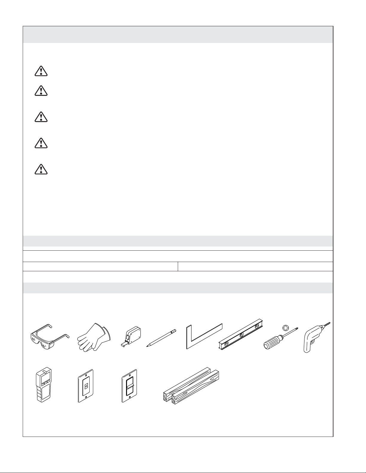
Specifications
Electrical Service
Light 120 V, 60 Hz, 0.4 A
Tools and Materials
Plus:
• Wire Cutter/Stripper
• Assorted Drill Bits
• Framing and Drywall Tools
• Framing and Drywall Fasteners
Stud
Finder
1337913-2-A 2 Kohler Co.
GFCI/RCD
Receptacle
Dimmer
Switch
2x4 Lumber
(Recess-Mount Only)
Before You Begin
CAUTION: Risk of personal injury. Medicine cabinets are very heavy. Get assistance lifting the
cabinet.
CAUTION: Risk of electric shock. For surface-mount installation, side mirror kit K-99012 or wood
kit K-99675 is required to enclose exposed electrical wiring.
NOTICE: Risk of property or product damage. The location of the cabinet is critical. Make sure that the
door will clear all obstacles (such as a faucet or light fixture). Ensure that any obstacles behind the finished
wall will not be damaged during the cutting and/or drilling process.
IMPORTANT! Reroute any electrical wires or water supply piping from the wall cavity. If you encounter
drain or vent piping or if your wall is load-bearing, consult a professional before proceeding.
IMPORTANT! The cabinet is designed for either right or left door swing (except K-99011-TLC).
NOTE: Recessed-Mount Installation: The wall cavity must be framed. The cabinet must be secured to the
framing studs.
Observe all local building codes.
This medicine cabinet is for recessed- or surface-mount installations. Follow the instructions that
apply to your chosen installation.
The appearance of your medicine cabinet may differ from the medicine cabinet illustrated. The
installation steps still apply.
This installation is easiest when performed by two people.
When determining the height of the product, verify that the doors will clear all obstacles (such as a
faucet or light fixture). A minimum distance of 3″ (76 mm) is required.
Kohler Co. 3 1337913-2-A
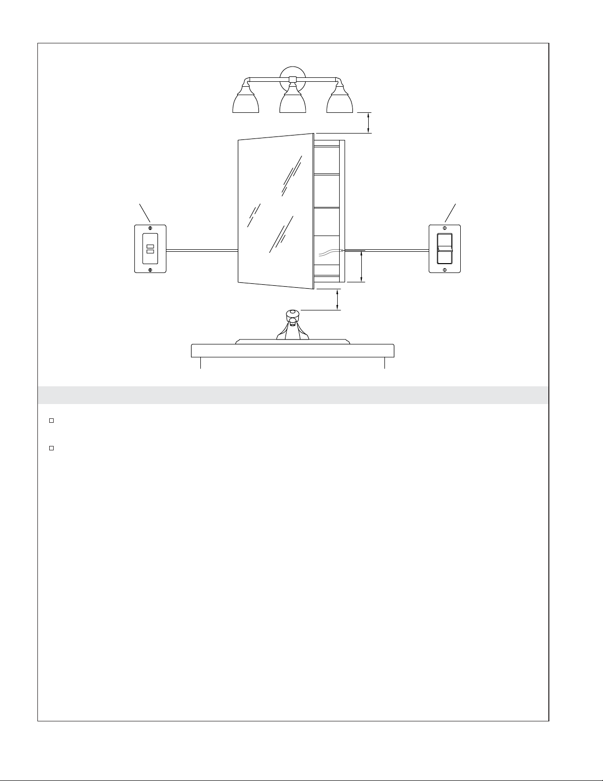
3" (76 mm)
GFCI/RCD
Receptacle
5-1/2"
(127 mm)
3" (76 mm) Min
Dimmer
Switch
Roughing-In
When determining the height of the product, verify that the door will clear all obstacles (such as a
faucet or light fixture). Provide a minimum distance of 3″ (76 mm).
Plan for the location of the dimmer switch and the GFCI/RCD receptacle. The electrical wires
should enter the power bar 5-1/2″ (127 mm) from the bottom of the mirror.
1337913-2-A 4 Kohler Co.
Recess-Mount Installation
Surface-Mount Installation
YX
K-99003-TLC
28-1/4"
(718 mm)
X
K-99007-TLC
K-99009-TLC
K-99011-TLC
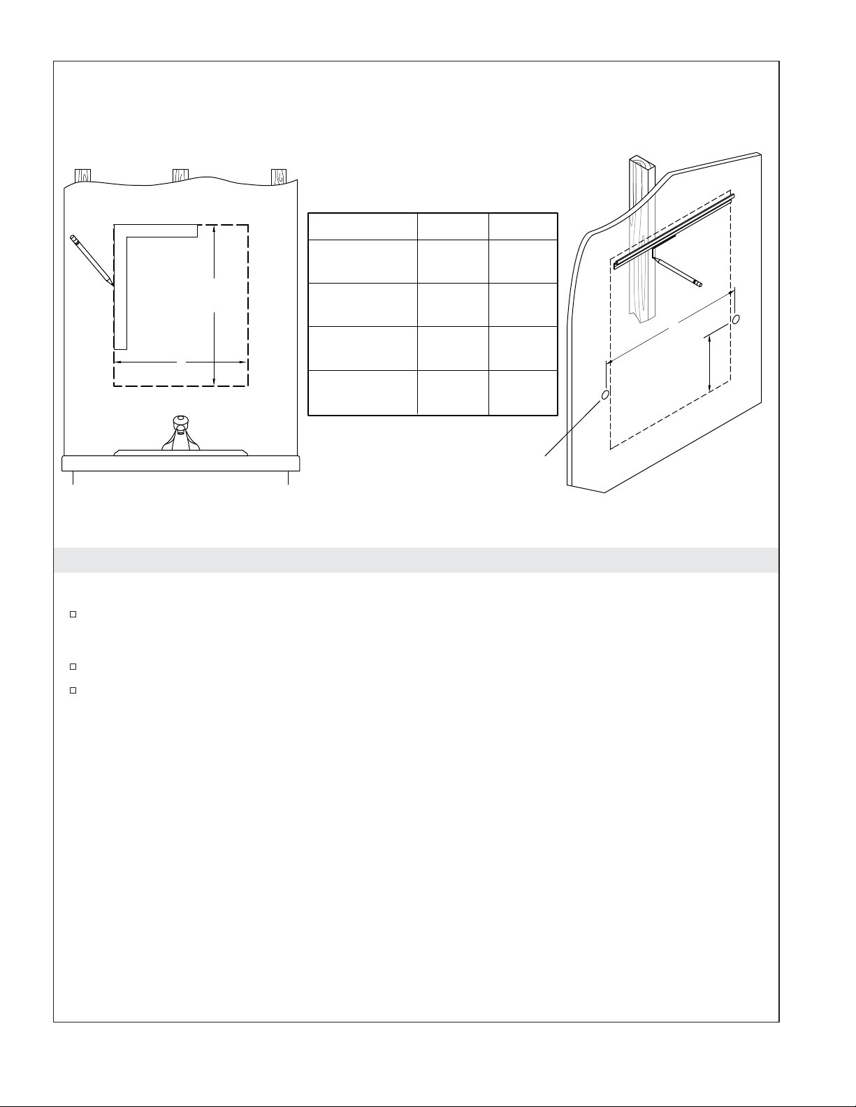
1. Prepare the Site
Recess-Mount Installation
Measure and mark the cutout for your model.
Surface-Mount Installation
19-1/2"
(495 mm)
23-1/2"
(597 mm)
33-1/2"
(851 mm)
39-1/2"
(1003 mm)
19-1/8"
(486 mm)
23-1/8"
(587 mm)
33-1/8"
(841 mm)
39-1/8"
(994 mm)
Ø 3/4"
(19 mm)
Y
4-5/8"
(117 mm)
Mark the mounting bar position and stud locations.
Determine the electrical wire hole locations according to the dimensions shown above for your
product.
Kohler Co. 5 1337913-2-A
Cabinet Only:
2-5/16" (59 mm)
Cabinet + Surround:
Ø 3/4"
(19 mm)
1-7/8" (48 mm)
4-5/8"
(117 mm)
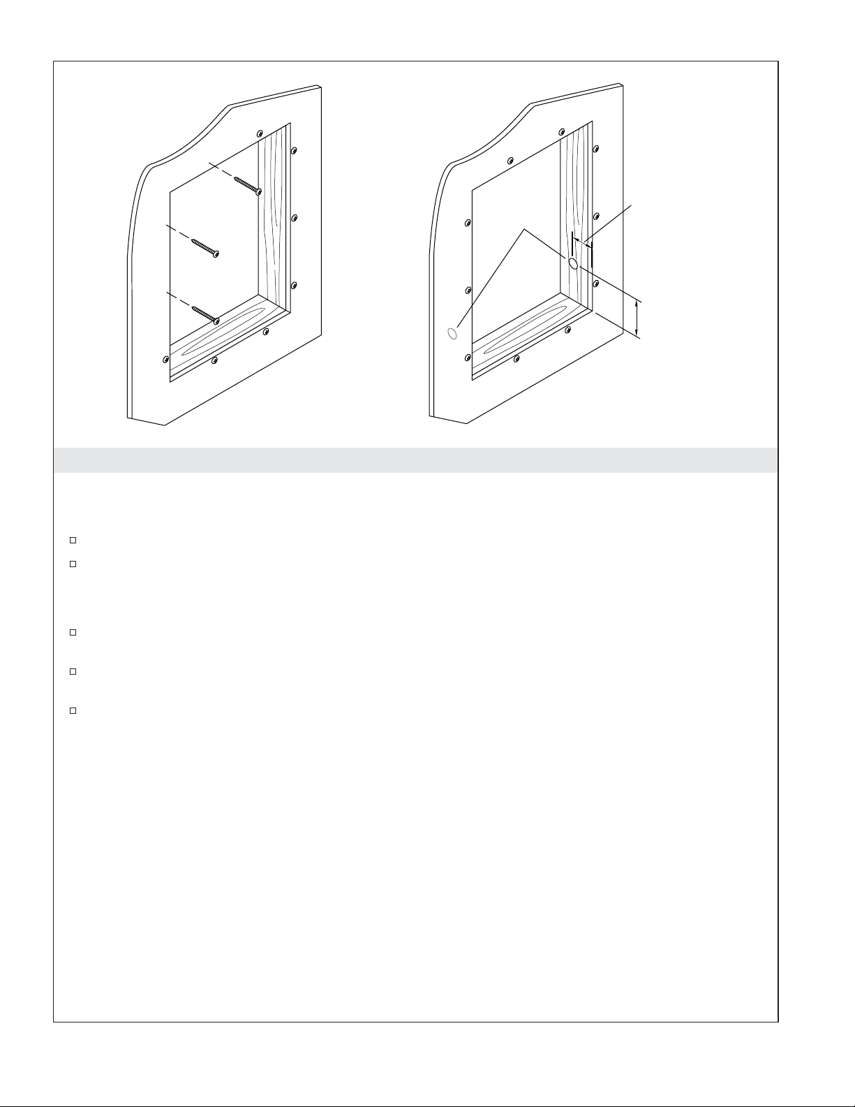
2. Recess Mount - Construct the Framing
NOTE: The following instructions are for recess-mount only. For surface-mount installation, refer to the
″Surface-Mount″ sections.
Using a jigsaw or keyhole saw, carefully remove the finished wall material from the marked cutout.
Frame out the wall cavity. If needed, install a header.
IMPORTANT! Hole location in the framing is critical for electrical wire alignment with the cabinet. If you
plan to install an optional decorative surround, use the dimension specified for the cabinet plus surround.
For cabinet only installation: Mark the center of the hole 4-5/8″ (117 mm) from the bottom of the
cavity, and 2-5/16″ (59 mm) from the finished wall.
For cabinet plus surround: Mark the center of the hole 4-5/8″ (117 mm) from the bottom of the
cavity, and 1-7/8″ (48 mm) from the finished wall.
Drill a 3/4″ (19 mm) hole into each side of the framed cavity at the marked locations.
1337913-2-A 6 Kohler Co.
Ø 3/4"
(19 mm)
Recess-Mount Installation
20"
(508 mm)
Surface-Mount Installation
Ø 3/4"
(19 mm)
4-5/8"
(117 mm)
20"
(508 mm)
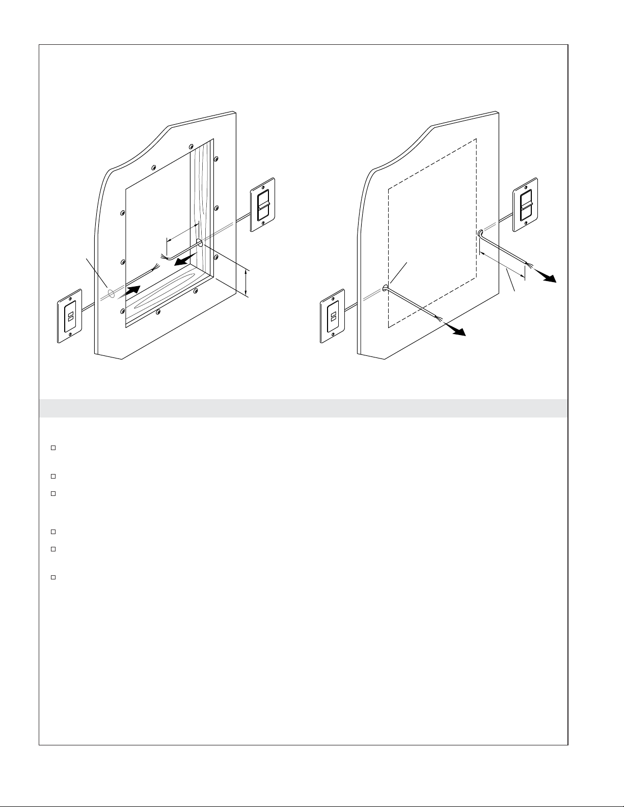
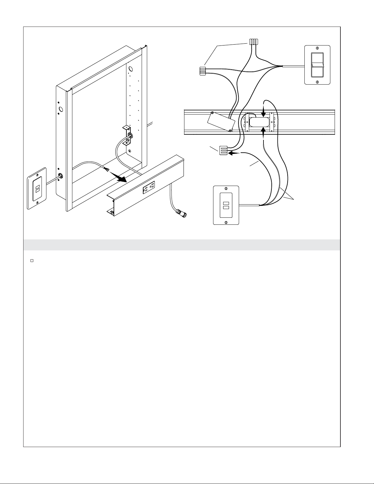
3. Route the Wiring
Recess-Mount Installation
Drill a 3/4″ (19 mm) hole into each side of the framed cavity, located 4-5/8″ (117 mm) from the
bottom of the cavity.
Route the GFCI/RCD receptacle and dimmer switch wires through the holes in the framing.
The wiring should extend at least 20″ (508 mm) from each hole.
Surface-Mount Installation
Drill two 3/4″ (19 mm) holes for the electrical wire locations.
Route the GFCI/RCD receptacle and the dimmer switch wires through the holes in the finished
wall.
The wires should extend at least 20″ (508 mm) from each hole.
Kohler Co. 7 1337913-2-A
Decorative
Surround
(Optional)
K-99011-TLC Only
All Other Models
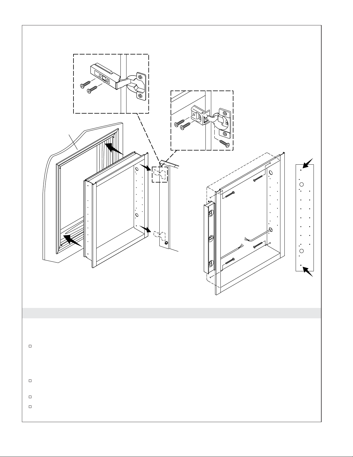
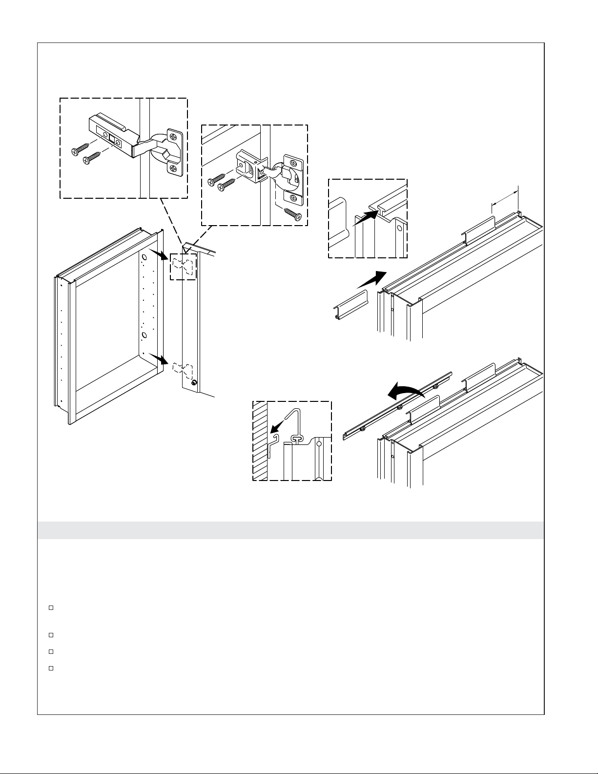
4. Recess-Mount - Install the Cabinet
NOTE: The following instructions are for recess-mount only. For surface-mount installation, refer to the
″Surface-Mount″ sections.
If purchased, install the decorative surround before installing the medicine cabinet. Follow the
instructions packed with the surround.
IMPORTANT! Never leave the door supported with only one hinge attached. Get assistance supporting
the door.
Open and remove the door(s). While supporting the door, remove the screws from the bottom hinge
first.
With assistance, position the cabinet into the cutout, and hold in place.
Use the screws provided to mount the cabinet to the framing studs using each of the four mounting
holes.
1337913-2-A 8 Kohler Co.
3/32"
3/16"
1"
(25 mm)
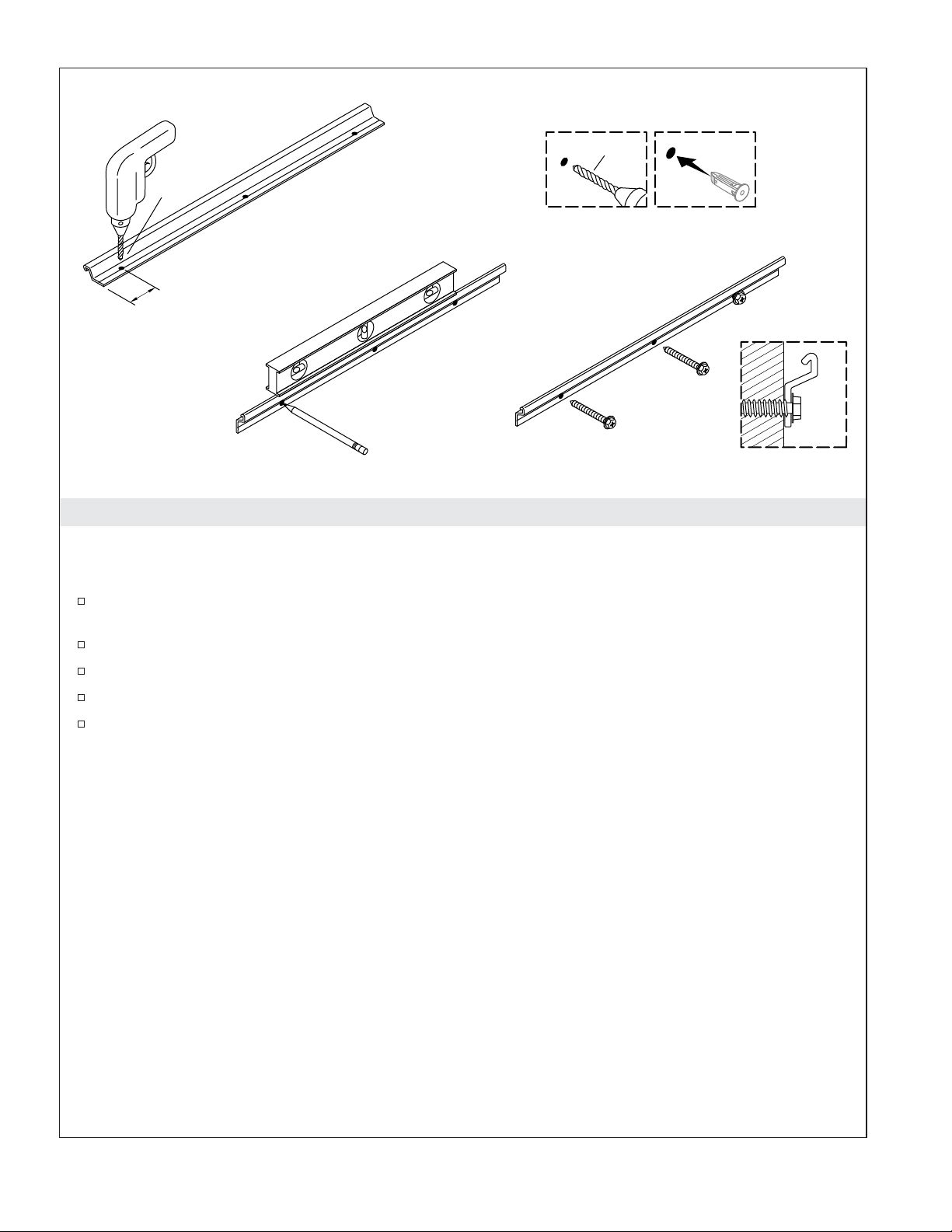
5. Surface-Mount - Install the Mounting Bar
NOTE: The following instructions are for surface-mount only. For recess-mount installation, refer to the
″Recess-Mount″ sections.
Using a 3/16″ drill bit, drill three holes on the groove of the mounting bracket. Position one hole at
a stud location.
Mark hole locations on the wall.
Drill holes at the marked locations on the wall.
Insert anchors (not provided) where needed.
Secure the mounting bar with three 2″ hex head screws or screws provided with the anchors.
Kohler Co. 9 1337913-2-A
K-99011-TLC Only
All Other Models
2" (51 mm)
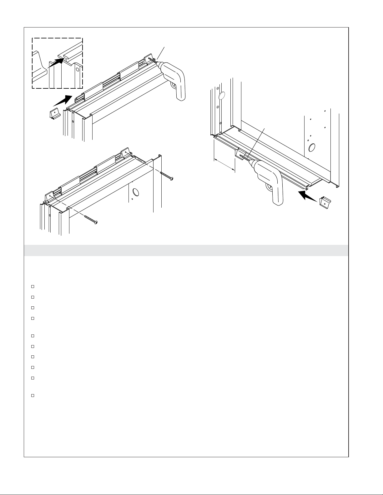
6. Surface-Mount - Hang the Cabinet
NOTE: The following instructions are for surface-mount only. For recess-mount installation, refer to the
″Recess-Mount″ sections.
IMPORTANT! Never leave the door supported with only one hinge attached. Get assistance supporting
the door.
Open and remove the door(s). While supporting the doors, remove the screws from the bottom
hinge first.
Slide the hanger hooks onto the top T-slot.
Position each hook 2″ (51 mm) from the ends of the cabinet.
Lift the cabinet onto the mounting bar. Make sure that the hanger hooks engage the bar.
1337913-2-A 10 Kohler Co.
3/32"
3/32"
2" (51 mm)
7. Surface-Mount - Secure the Cabinet
NOTE: The following instructions are for surface-mount only. For recess-mount installation, refer to the
″Recess-Mount″ sections.
Slide a clip onto each end of the top T-slot.
Center the cabinet on the wall as desired.
Using a 3/32″ drill bit, drill pilot holes into the wall.
If anchors are needed, remove the cabinet and install anchors into the wall at the pilot hole
locations.
Secure the clips with 1-1/2″ screws (provided).
Slide two clips onto the bottom T-slot.
Position each clip 2″ (51 mm) from the ends of the cabinet.
Using a 3/32″ drill bit, drill pilot holes into the wall.
If anchors are needed, remove the cabinet and install anchors into the wall at the pilot hole
locations.
Secure the clips with 1-1/2″ screws (provided).
Kohler Co. 11 1337913-2-A
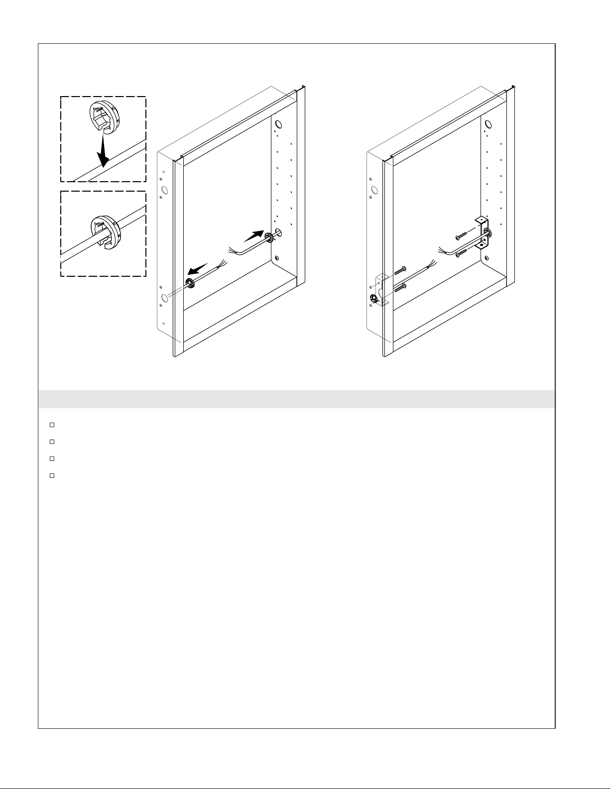
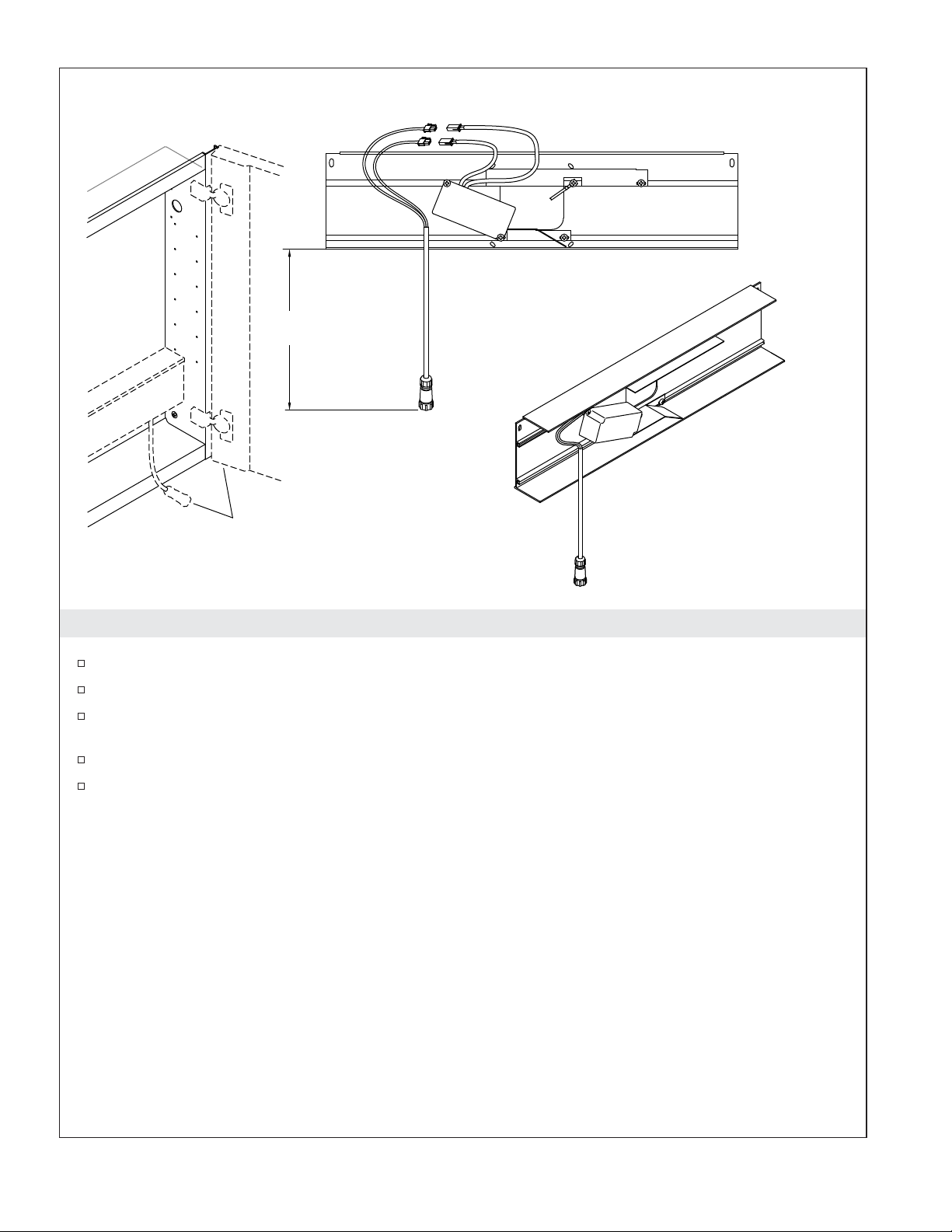
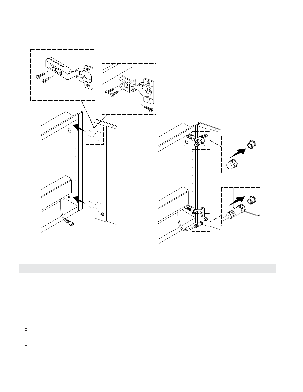
8. Install the Brackets
Install a wire gasket onto both electrical wires, close to the side panel hole.
Press each gasket into the hole.
Align the brackets with the side panel holes as shown.
Secure each bracket with two screws (provided). Avoid pinching the electrical wires while securing
the brackets.
1337913-2-A 12 Kohler Co.
Wire Connectors
Load
(Black)
Line
(White)
Ground (Green)
Wire Connector
9. Connect the Dimmer Switch
Connect the electrical wiring from the dimmer switch to the proper connectors on the power bar as
shown.
Kohler Co. 13 1337913-2-A
Wire Connectors
Wire Connector
Ground
(Green)
Line (White)
and Load
(Black)
10. Connect the GFCI/RCD Receptacle
Connect the electrical wiring from the GFCI/RCD receptacle to the proper connectors on the power
bar as shown.
1337913-2-A 14 Kohler Co.
4"
(102 mm)
Position the cable
near the door.
11. Connect the Door Cable
Position the cable on the side of the power bar that will be closest to the door.
Connect the door cable to the power supply connectors on the power bar.
The cable should extend 4″ (102 mm) from the bottom of the power bar. Coil any excess cable inside
the box.
Install the slotted grommet around the cable and into the power bar slot.
Install the plug in the remaining open slot on the back of the power bar.
Kohler Co. 15 1337913-2-A
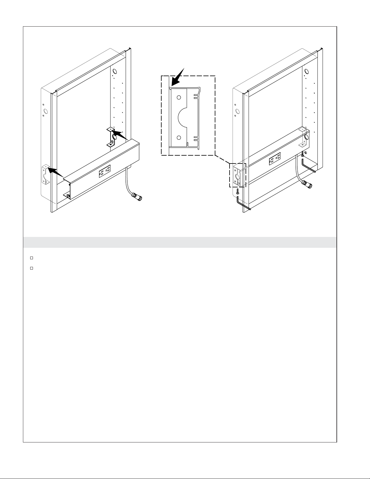
12. Install the Power Bar
Position the power bar into the cabinet. Make sure that the top of the box clips over each bracket.
Secure the box in place with the two screws (provided).
1337913-2-A 16 Kohler Co.
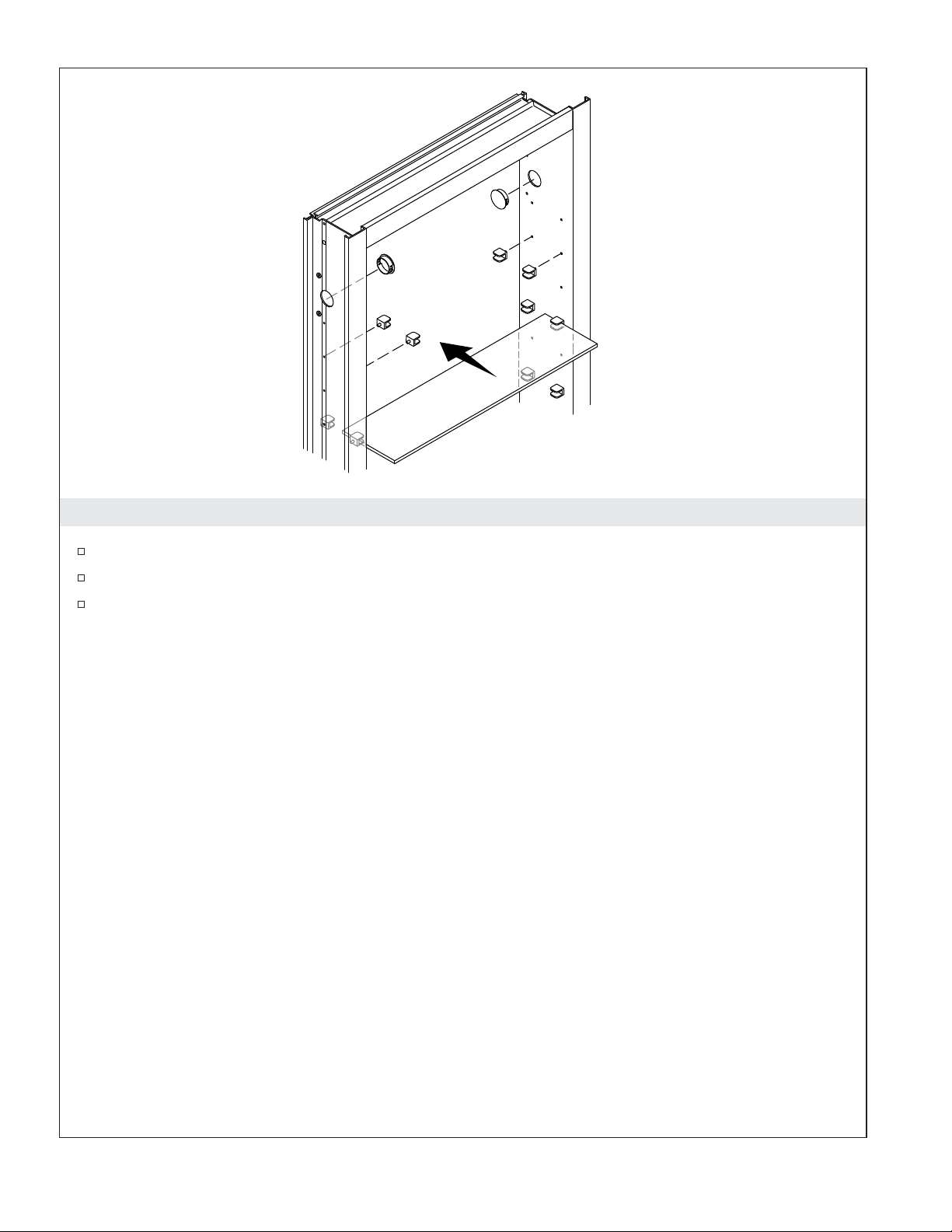
13. Install the Shelves
Determine the shelf locations and insert the slotted pins into the holes in the sides of the cabinet.
Install the shelves between the slots of the pins.
Install the caps to the unused electrical holes near the top of the cabinet.
Kohler Co. 17 1337913-2-A
K-99011-TLC Only
All Other Models
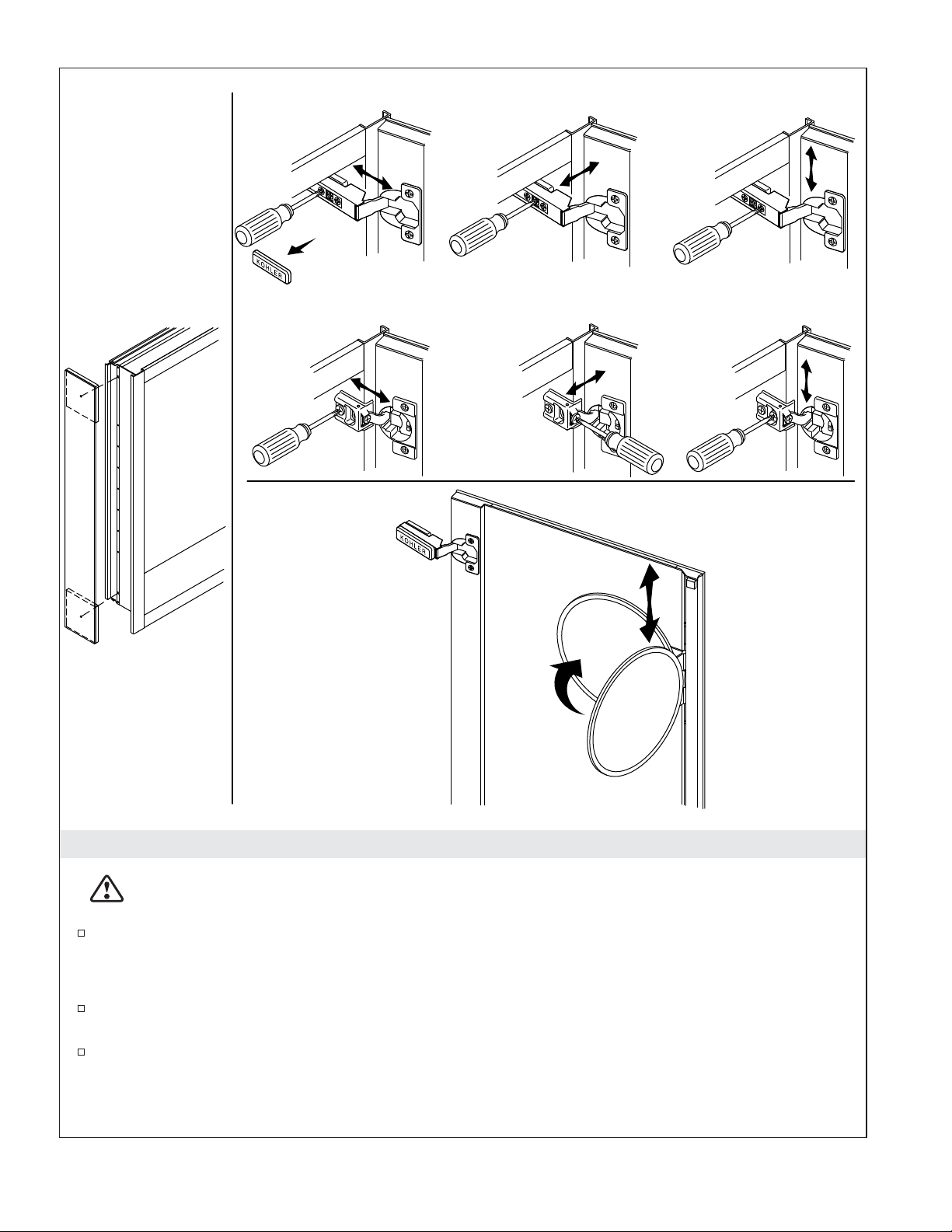
14. Install the Door
IMPORTANT! Never leave the door supported with only one hinge attached. Get assistance supporting
the door.
IMPORTANT! Make sure that the cable does not get pinched you close the door.
NOTE: Reattach the top hinge first.
Align the hinges with the hinge holes in the side of the cabinet.
While supporting the door, secure the top hinge to the cabinet with the three screws.
Continue supporting the door while securing the bottom hinge with the three screws.
Align the tab on the end of the cable with the adapter slot at the bottom of the door.
Press the cable connector onto the adapter.
Align the tab on the cap with the adapter slot at the top of the door, then press in place.
1337913-2-A 18 Kohler Co.

Install the Door (cont.)
Test opening and closing the door for smooth operation. Make sure that the cable does not get
pinched.
If the door binds, make adjustments to the hinges. Refer to the ″Adjust the Door″ section.
Kohler Co. 19 1337913-2-A
K-99011-TLC Only
Surface-Mount
All Other Models
15. Complete the Installation
CAUTION: Risk of electric shock. For surface-mount installation, side mirror kit K-99012 or wood
kit K-99675 is required to enclose exposed electrical wiring.
For surface-mount installation: Install side mirror kit K-99012 or wood kit K-99675 to enclose the
exposed electrical wiring.
Adjust the Height
Access the height adjustment screws through holes at the top and bottom of the main mirror
housing.
Refer to the illustration above and note the screwdriver location for the desired adjustment.
Adjust the Mirror
1337913-2-A 20 Kohler Co.
 Loading...