

Kohler K-99003T-R, K-99003T-L, K-99005T-R, K-99005T-L, K-99009T Installation Instructions Manual
Page 1
-1-
VERDERA
INSTALLATION INSTRUCTIONS
MIRRORED CABINET
K-99003T-R/K-99003T-L
K-99005T-R/K-99005T-L
K-99009T
, 2013
Copyright Kohler China Ltd., 2013
13-1 528437
BEFORE YOU BEGINBEFORE YOU BEGIN
·
·
·
·
Please read these instructions carefully to familiarize
yourself with the required tools, materials, and installation
sequences. Follow the sections that pertain to your
particular installation . This will help you avoid costly
mistakes. In addition to proper installation, read all
operating and safety instructions.
All information in these instructions is based upon the
latest product information available at the time of
publication. Kohler China. reserves the right to make
changes in product characteristics, packaging, or
availability at any time without notice.
These instructions contain important care, cleaning, and
warranty information-
Before installation carefully inspect the new fixture for any
signs of damage.
Be
careful when opening the door to avoid pinching
fingers.
Don't use acidic or alkalic cleaners or
alcohol to clean the surface. Use a dampened cloth to
clean.
Electrical wiring
may need to be relocated.
Use anchors
(not provided) rated for the loaded weight of this
product. Refer to the anchor manufacturer's
instructions.
This cabinet is designed for
either right or left door swing. Check the wall cavity for
obstructions.
please leave instructions for the
consumer.
WARNING: Risk of injury or product damage.
WARNING:
CAUTION: Risk of electric shock.
CAUTION: Risk of property damage.
Important Information:
·
·
·
·
-
TOOLS REQUIREDTOOLS REQUIRED
6
4
Anchors (as needed)
()
1219820-T01-A
Page 2
-2-
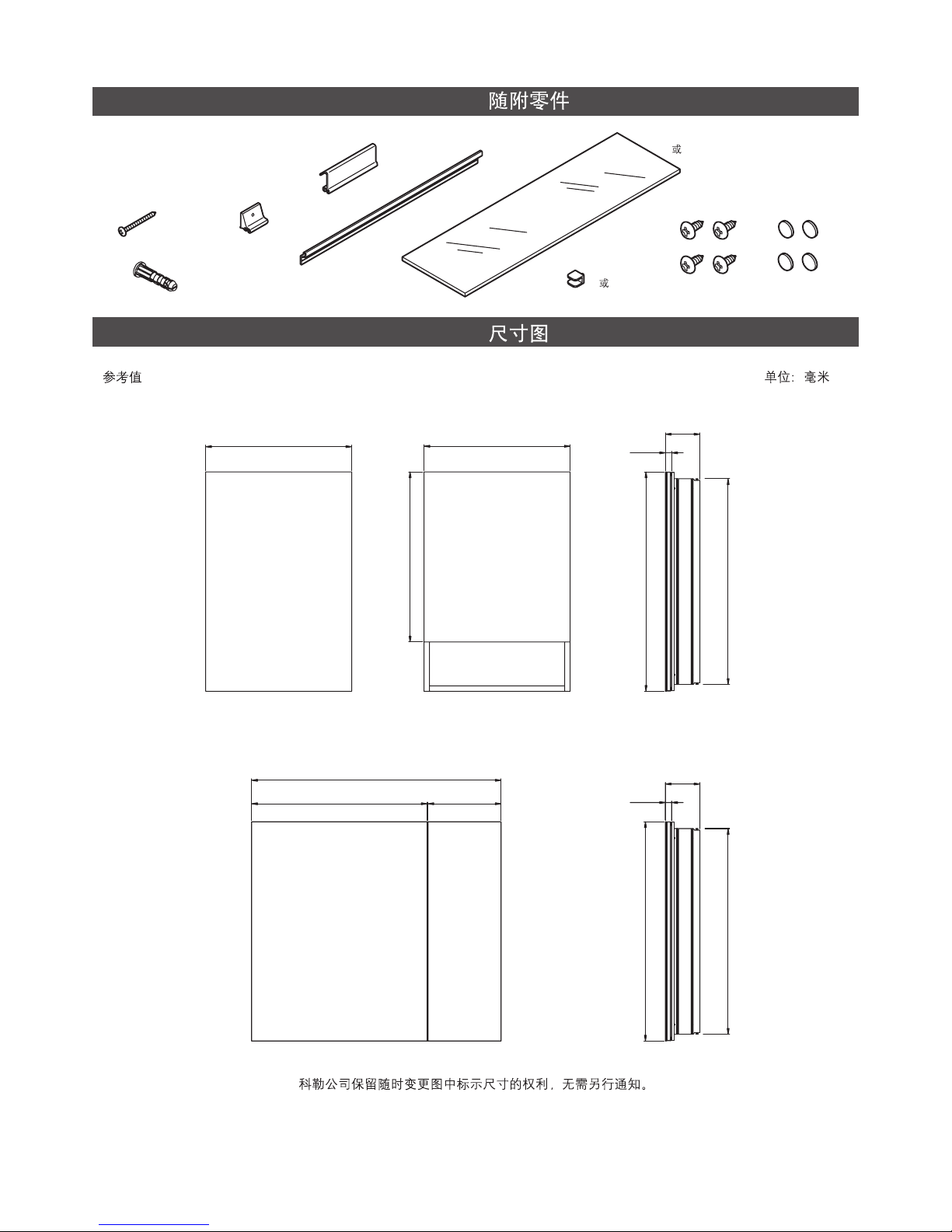
Kohler reserves the right to change marked dimensions without prior notice.
ROUGHING-IN
UNIT : mm
Reference Value
PARTS SUPPLIEDPARTS SUPPLIED
(10)
(10)
(4)
(4)
(4)
(2)
(1)
(2 or 3)
(2 3)
(8 or 12)
(8 12)
K-99003T-L
K-99003T-R
K-99005T-L
K-99005T-R
K-99009T
508
508
120
22
591
762
715
866
610 254
22
120
762
715
1219820-T01-A
Page 3
-3-
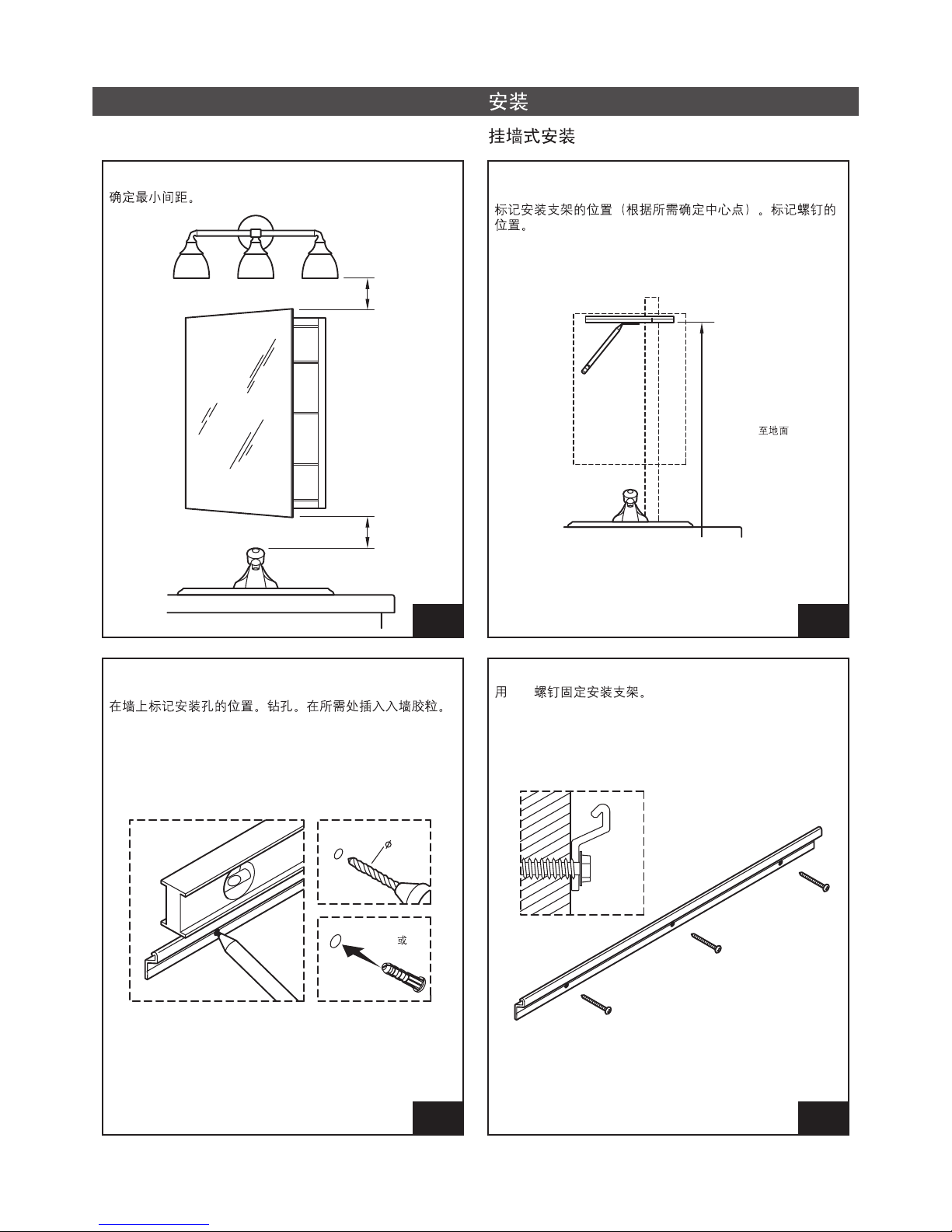
INSTALLATION
Surface-Mount Installation
STEP
2
STEP
1
Verify minimum clearances.
Mark the mounting bar position (centered as desired). Mark
stud locations.
76mm
76mm
(1905 mm) To Floor
(1905 mm)
STEP
3
Mark hole locations on the wall. Drill holes. Insert anchors
where needed.
Or
6
STEP
4
Secure the bar with round-head screws.
1219820-T01-A
圆头
Page 4

-4-
STEP
7
Lift the cabinet onto the mounting bar. Ensure the hooks
engage the bar.
STEP
6
Slide the hanger hooks onto the top T-slot as shown.
T
51mm
STEP
5
Rotate the cabinet for right or left door swing with KOHLER
logo on the bottom of the outside mirror.
KOHLER
STEP
8
Slide two clips onto the T-slot. Ensure the cabinet is
centered as desired. Drill pilot holes.
T
3/32"
1219820-T01-A
滑
Page 5

Measure and mark the cutout.
718mm
"A"
76mm Min
76mm
-5-
STEP
12
STEP
9
If needed, insert anchors into the wall. Secure the clips with
round-headed long screws.
STEP
10
Slide two clips onto the bottom T-slot. Drill pilot holes and
secure with round-headed long screws.
T
51mm
3/32"
STEP
11
Cut-Out Dimensions.
Model
A=Width
A=
K-99003T
K-99005T
K-99009T
470mm
470mm
828mm
1219820-T01-A
Page 6

STEP
15
Secure the cabinet to the framing.
STEP
14
With help, lift and hold the cabinet in the cutout.
-6-
STEP
13
Cut away the drywall.
1219820-T01-A
Page 7

Installation and Adjustment of Accessories
STEP
2
If needed, align the door.
STEP
3
To adjust mirror height, slide up or down.
IMPORTANT! Rotate mirror in before closing the door.
-7-
STEP
4
To adjust mirror tension, remove the end cap and mirror.
Turn tension knobs.
STEP
1
Install the clips. Insert the shelves between the clips.
1219820-T01-A
Page 8

Installation of Side Mirror (Note: Not
necessory for recess-mount installation.)
-8-
STEP
2
STEP
1
Find the two bracket locations on each side of the cabinet.
Align the brackets with the mounting holes.
Left Side Right Side
STEP
4
STEP
3
Secure the brackets with the screws.
round-headed short Cover the screws with the screw caps.
1219820-T01-A
 Loading...