

Kohler K-98741-K1 Installation And Care Manual

Installation and Care Guide
Lighted Rain Panel for DTV+
K-98741-K1
Français, page ″Français-1″
Español, página ″Español-1″
1235394-2-A
IMPORTANT INSTRUCTIONS
WARNING: When using electrical products, basic precautions should always be followed,
including the following:
DANGER: Risk of electrocution. Disconnect the electricity to the working area at the main breaker
panel before performing the installation steps for hardwiring.
WARNING: Risk of electric shock. Connect only to circuits protected by a Ground-Fault
Circuit-Interrupter (GFCI)*. Grounding is required. The unit should be installed and grounded by a
qualified service representative.
WARNING: Risk of electric shock. A qualified electrician should route all electrical wiring.
WARNING: Risk of electric shock. Disconnect power before servicing.
WARNING: Risk of injury or property damage. Please read all instructions thoroughly before
beginning installation.
NOTICE: Follow all plumbing, electrical, and building codes.
NOTICE: Provide unrestricted service access to the Power Data Supply (PDS).
*Outside North America, this device may be known as a Residual Current Device (RCD).
___________________________________________________________________________________________________
Operation with DTV+
To connect the lighted rain panel to the DTV+ system, the K-99695 system controller is required.
The provided data cable is used to connect the lighted rain panel PDS to the system controller.
Refer to the ″DTV+ System Layout″ section in this guide.
Before Operating the System For the First Time:
Download and install the latest software for connected components. This may take an hour or more to
complete based on system configuration and internet connection speed. Do not disconnect the power from
any components during software download and installation.
Specifications
Ambient Temperature Max 104°F (40°C)
Maximum Relative Humidity 95% non-condensing
Power Data Supply (PDS) 100-240 VAC, 50-60 Hz, 1.7 A
Data Cable Length 25’ (7.6 m)
Chroma Power Cable Length 30’ (9.14 m)
1235394-2-A 2 Kohler Co.
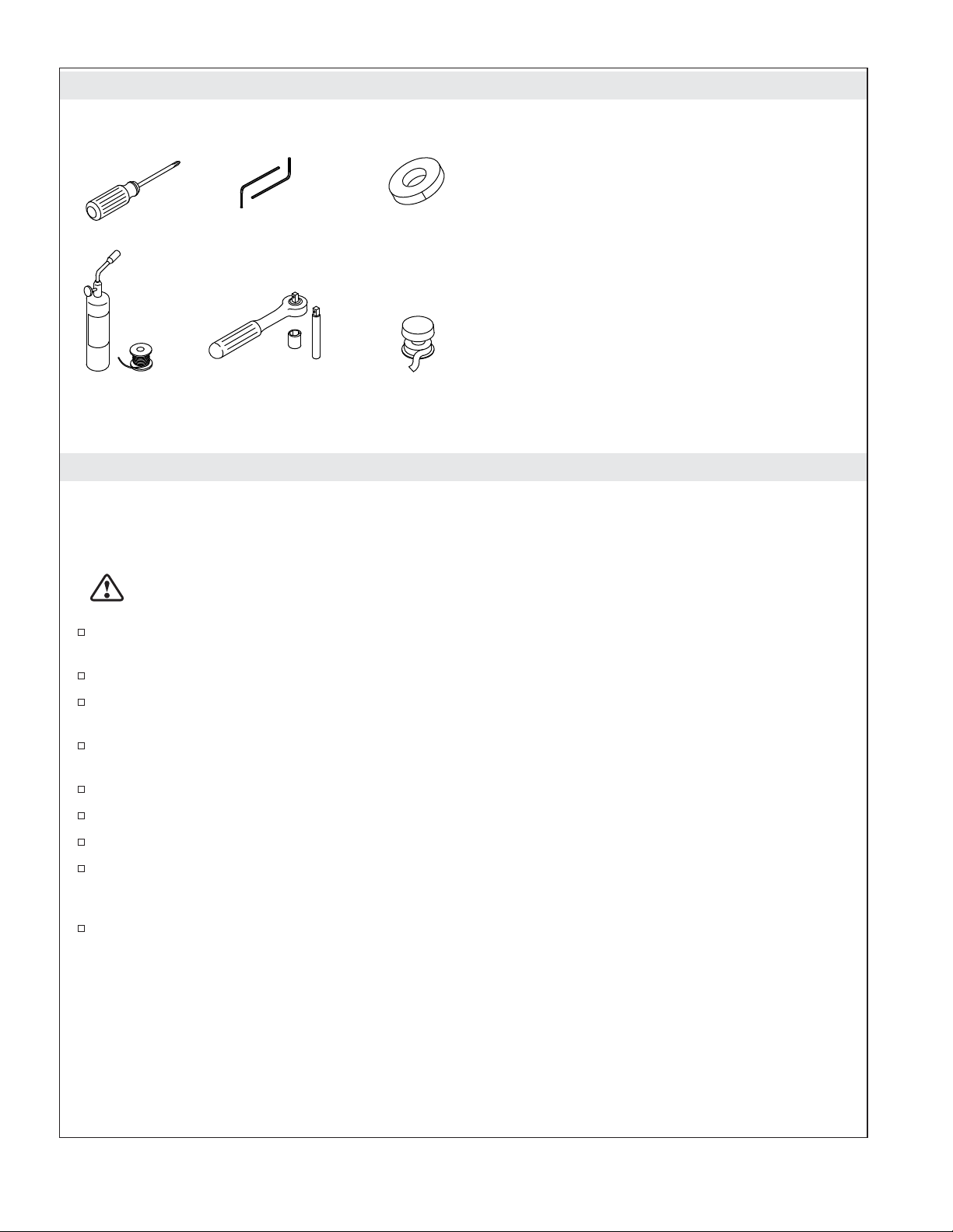
Tools and Materials
Plus:
Note: All nipples & fittings 1/2" NPT
• (4) 2-1/2" nipples
• Female fittings
• 1/2" copper tubing
• 2x4s and 2x6s
• Conventional woodworking tools and materials
• #8 x 1-1/2" drywall screws
• Standard wood or drywall screws
• Electrical Wire
• Wire Cutters/Strippers
Soldering
Supplies
5/64", 5/32" Masking
Tape
Socket Wrench &
11 mm or 7/16"
Socket and Extension
Sealant
Tape
Before You Begin
NOTICE: Choose an automatic compensating valve with the appropriate minimum flow rating to ensure
your valve will provide safety at the lowest flow rates.
•
For a showerhead rated at 2.5 gal/min (9.5 l/min) maximum, use with an automatic compensating
valve rated at 2.0 gal/min (7.6 l/min) or less.
CAUTION: Risk of personal injury. If the rain panel is not securely held in place during
installation, the product may fall. Get help installing the light panel assembly and waterways.
Read these instructions and determine the locations of all required components before beginning
installation.
This product is designed for ceiling-mount installation only. Do not install to a shower wall.
This manual covers vertical installation of the Power Data Supply (PDS) in a service closet or 2x6
stud pocket. If the wall is enclosed, an access panel must be provided for servicing.
The PDS may be mounted under floor joists. If mounting under the floor, the unit must not be
enclosed.
The PDS must be located within 30’ (9.14 m) of the rain panel.
If possible, locate the PDS within 25’ (7.62 m) of the system controller.
Inspect the supply piping for damage. Replace as necessary.
The PDS is intended for hardwire installation. Make sure electrical power can be provided to a
service closet or 2x6 stud framing with access panel, not more than 2’ (0.61 m) from the intended
PDS location.
To reduce the risk of electric shock, locate the PDS and overhead rain panel within proximity to
each other to allow each cable to have a drip loop.
Kohler Co. 3 1235394-2-A
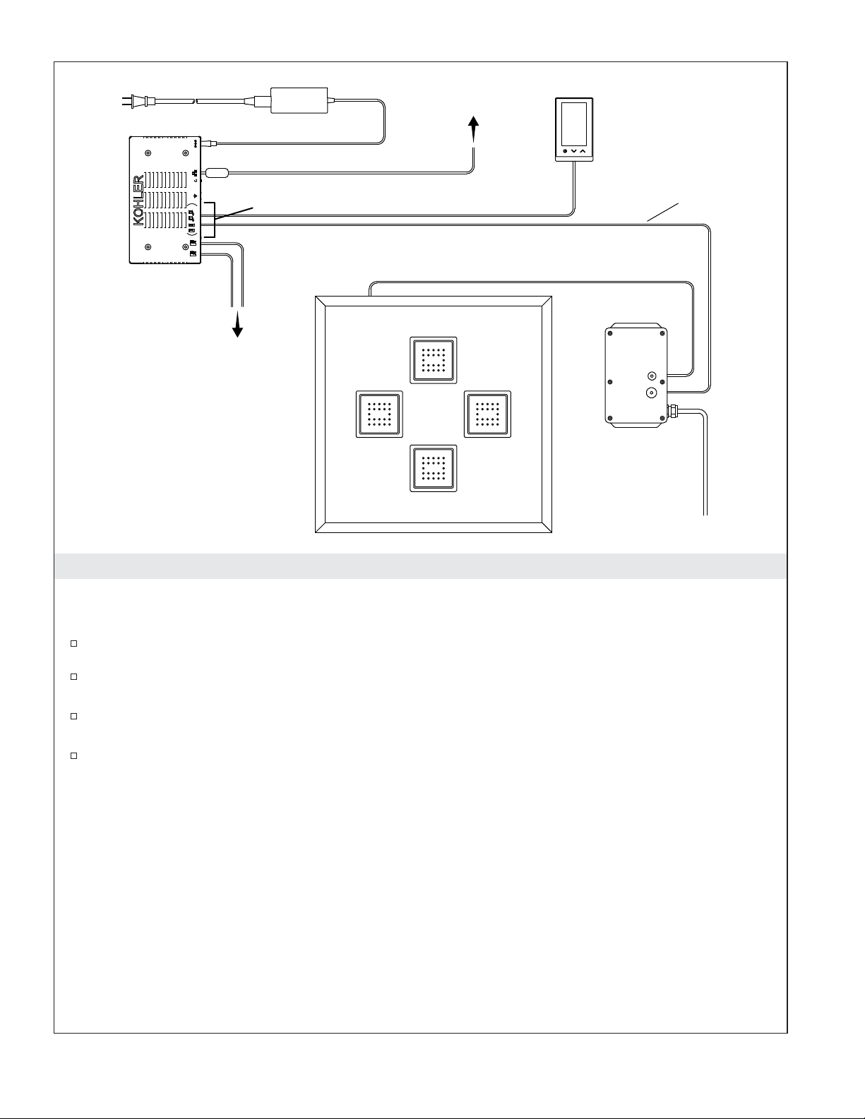
AC
Power
Router
Interface
(Up to Three)
Component Cable
Connections
Controller
Digital
Valve(s)
Rain Panel 100-240 VAC
1. DTV+ System Layout
25' (7.6 m)
Data Cable
30' (9.1 m) Chroma Power Cable
Power Data
Supply
The K-99695 system controller powers the interface(s) and controls the lighted rain panel and other system
components.
Determine the locations of all required components.
Route the 25’ (7.6 m) data cable from the PDS installation location to the controller installation
location. If the PDS is not within 25’ (7.6 m) of the controller, add an Ethernet-style extension cable.
Route the 30’ (9.14 m) chroma power cable from the PDS installation location to the rain panel
installation location.
For cable connections, refer to the ″Connect the Cables″ section.
Before Operating the System For the First Time:
Download and install the latest software for connected components. This may take an hour or more to
complete based on system configuration and internet connection speed. Do not disconnect the power from
any components during software download and installation.
1235394-2-A 4 Kohler Co.
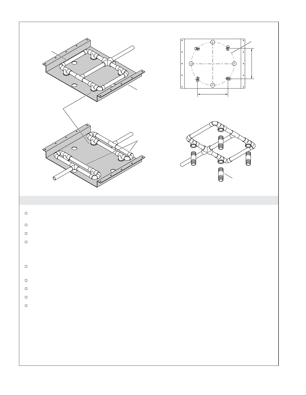
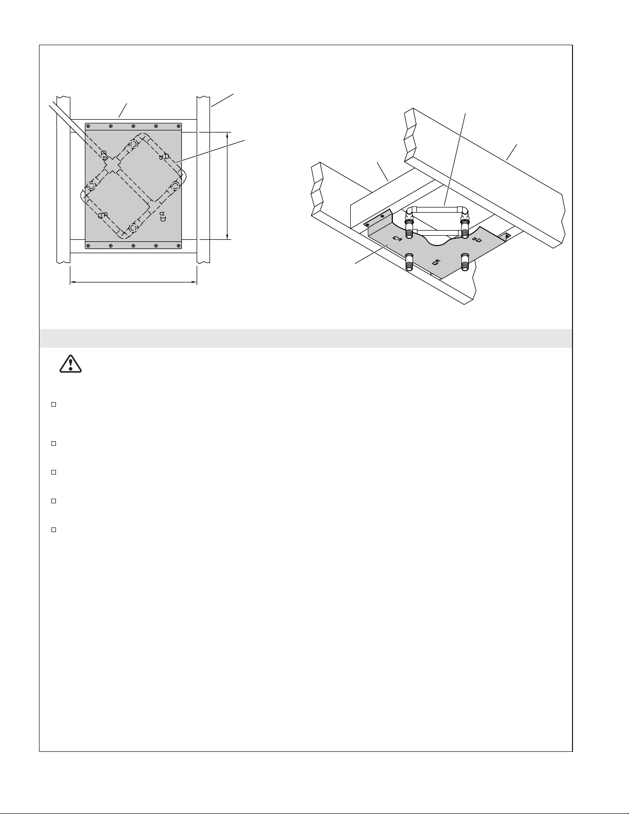
Pressure
Balancing
Loop
Single Supply
Soldering Template
Ø 9-5/8"
(244 mm)
6-3/4"
(172 mm)
Clamp each tee
to the template
Soldering
Template
6-3/4" (172 mm)
during soldering.
Multiple Supplies
Rigidly connect
to each other.
2. Install the Supply Piping
Route the water supply lines.
Use the provided soldering template to construct a pressure balancing loop.
Position tees in the loop(s) over each of the four raised locations on the template.
Solder the assembly while it is attached to the template.
1/2" NPT Nipple
IMPORTANT! For multiple supply lines: To maintain proper alignment of the tees with the product, the
pressure balancing loops must be rigidly connected to each other while on the soldering template.
Multiple supply lines: While on the soldering template, rigidly connect the two pressure balancing
loops to each other.
Remove the pressure balancing loop from the template.
Connect the pressure balancing loop to the water supply.
Do not strap the pipes.
Temporarily install a nipple to each tee. Do not use any sealant.
Kohler Co. 5 1235394-2-A
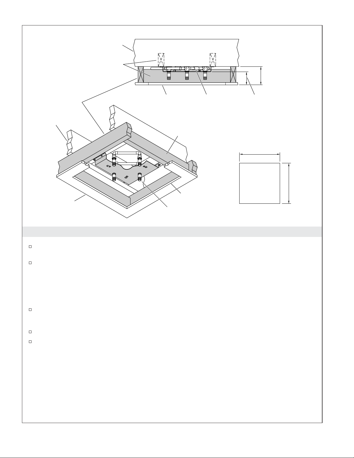
Bottom View
2x4
Ceiling Joist
Pressure
Balancing
Loop
Pressure
Balancing Loop
2x4
12-1/4"
(311 mm)
Soldering
Template/Cradle
14-1/2" (368 mm)
3. Install the Support Framing
WARNING: Risk of injury or property damage. Template/cradle must be properly secured to
support the weight of the rain panel. Secure the cradle to the framing using a minimum of six #8 x
1-1/2″ long drywall screws.
If installing the rain panel to a finished ceiling, remove drywall from the installation location.
Ceiling
Joist
IMPORTANT! The soldering template must be secured to structural framing.
Attach a mounting surface to structural framing of the ceiling using #8 x 1-1/2″ long drywall
screws.
Construct the support framing using 2x4 studs as shown in the illustration above. The face of each
2x4 should be installed flush with the face of the ceiling joists.
Position the soldering template/cradle under the pressure balancing loop(s), as illustrated. Attach
the cradle to the support framing.
Do not strap the pipes.
1235394-2-A 6 Kohler Co.
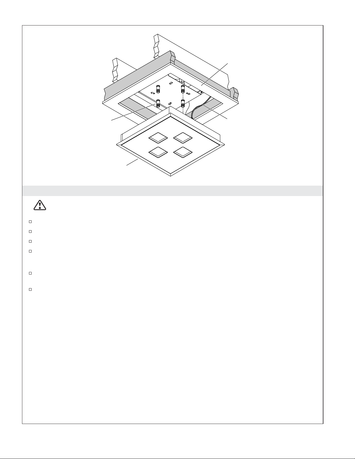
Ceiling Joist
2x4
5" (127 mm) Typical
4-7/8" (124 mm) Min
2x6
Cut/Modified
Ceiling
Joist
Finished Ceiling
Finished
Ceiling
2x4
Cutout
Nipple
Pressure
Balancing
Loop
3-5/8" (92 mm) Typical
3-1/2" (89 mm) Min
20-3/8" +/- 1/8"
(518 mm +/- 3 mm)
Cutout
4. Install the Finished Ceiling
Build a 5″ (127 mm) typical drop sill (including finished ceiling material) around the mounting
cradle using cut/modified 2x6 lumber.
Install the water-resistant wall board.
20-3/8"
+/- 1/8"
(518 mm
+/- 3 mm)
IMPORTANT! The ceiling cutout must be within the dimension limits specified above. The seal will not
cover gaps greater than 1/4″ (6 mm).
IMPORTANT! The balancing loop(s) must be centered within 1/8″ (3 mm) with the pipe nipples evenly
spaced from the edges of the rough opening.
Cut out a 20-3/8″ (518 mm) square at the installation location. The square must be within 1/8″ (3
mm) of the specified cut-out dimension to ensure the rough cut edges will be covered by the light
panel frame after installation.
Install the finished ceiling material (if using tile).
Verify that the finished drop sill is between 3-1/2″ (89 mm) and 3-3/4″ (95 mm) from the bottom of
the cradle.
Kohler Co. 7 1235394-2-A
Finished Ceiling
Pipe Nipple
Light Panel Assembly
Chroma
Power Cable
5. Install Pipe Nipples and Light Panel
CAUTION: Risk of personal injury. If the rain panel is not securely held in place during
installation, the product may fall. Get help installing the light panel assembly and waterways.
Remove the nipples.
Apply thread sealant to the threads of the nipples.
Reinstall the nipples to the tees/elbows.
Run water through the system to flush out any dirt or debris.
IMPORTANT! The following steps require two people.
Lift the light panel up to the installation location and attach the pre-routed chroma power cable to
the light panel assembly.
Insert the light panel into the rough opening of the finished ceiling and hold in place. The light
panel must be supported until it is secured by installing the adapters.
1235394-2-A 8 Kohler Co.
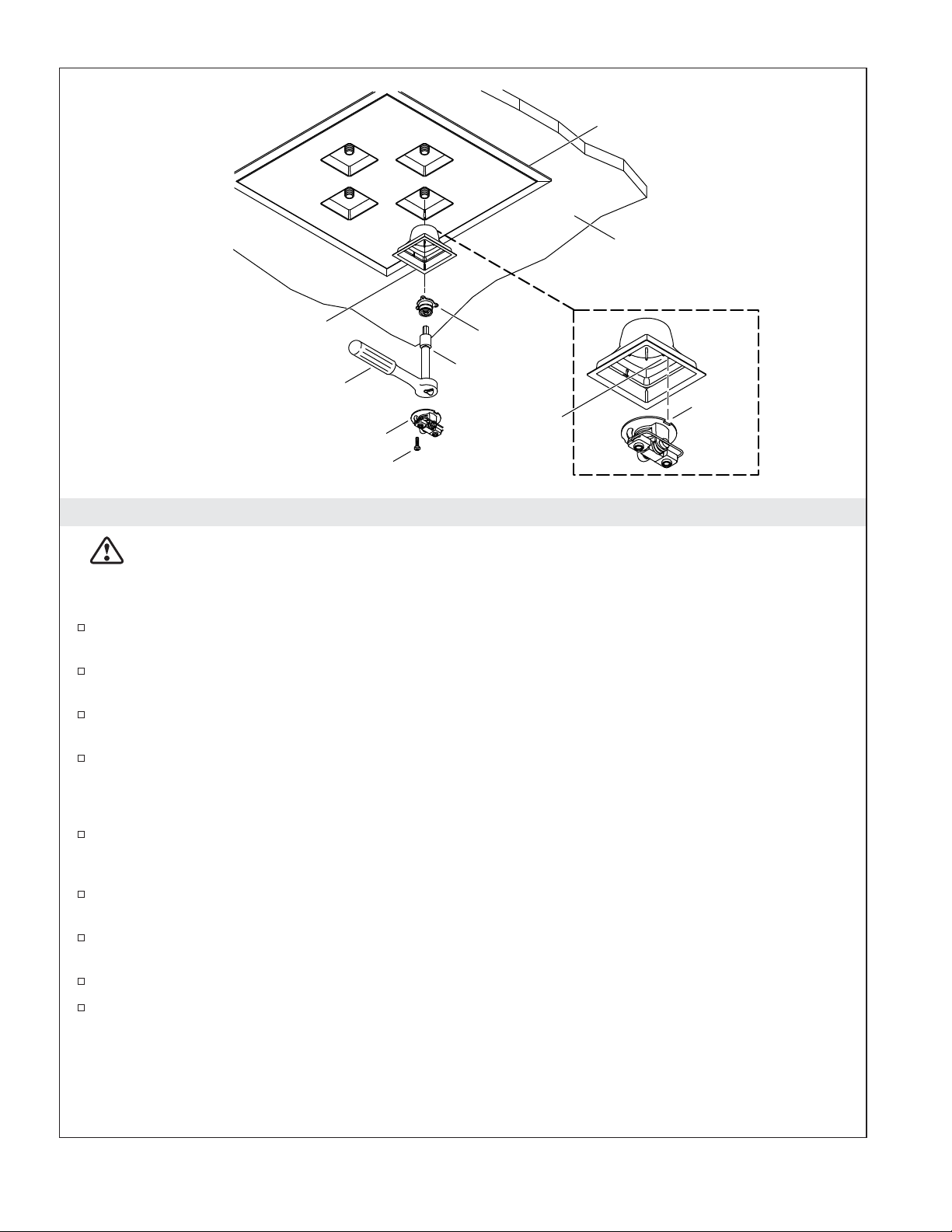
Light Panel Frame
Finished Ceiling
Escutcheon
Socket Wrench
With 11 mm Bit
Waterway
Screw
Adapter
Extension
Notch
Double Ribs
Inside Leak
Shield
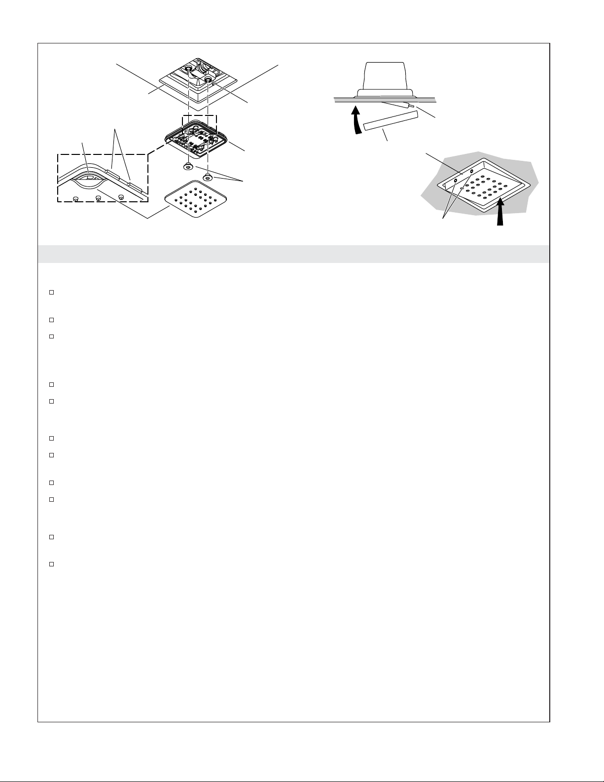
6. Install the Waterway
CAUTION: Risk of personal injury. If the rain panel is not securely held in place during
installation, the product may fall. Get help installing the light panel assembly and waterways.
IMPORTANT! The following steps require two people.
Insert an escutcheon into one of the four openings in the light panel. Orient the double ribs of the
escutcheon toward the center of the panel.
While another person holds the light panel in the rough opening, thread an adapter into the pipe
nipple.
While the other person continues to hold the panel, install the three remaining escutcheons and
adapters to hang the fixture.
Release the panel after the four adapters are installed. The panel will not be tight to the ceiling at
this time.
IMPORTANT! Secure the adapters sufficiently to create a water-tight seal for the pipe threads.
Secure each adapter using the 11 mm bit (provided) with the 11 mm or 7/16″ socket extension, and
socket wrench. Use masking tape to hold the bit in place to prevent it from falling off and causing
damage to your shower. The light panel should still sit loosely against the ceiling.
Install the waterway by aligning the notch in the waterway with the double ribs on the inside of the
leak shield.
Press the waterway into place over the adapter. Secure the waterway to the adapter with the screw
provided. Do not completely tighten at this time.
Repeat for the remaining waterways.
Tighten the screws evenly until the outer frame of the panel is against the ceiling, and the sealing
gasket is compressed.
IMPORTANT! If the light panel frame does not meet the ceiling within 1/32″ (1 mm), the pipe nipple is
too long. Check the rough depth. Try turning the threaded adapter further, or use a shorter pipe nipple.
Kohler Co. 9 1235394-2-A
Groove
Escutcheon
Ribs
Waterway
Ribs
Sprayface
Sprayhead
Hex Screws
Nozzle Membrane
Setscrews
7. Install the Trim
Attach the Sprayhead
Using a 5/32″ hex wrench, secure the sprayhead to the waterway with the two hex screws. Do not
overtighten.
Check that the sprayhead sits squarely within the escutcheon and tilts freely up and down.
Place the nozzle membrane over the sprayhead, aligning the long edge of the membrane with the
ribs.
NOTE: For optimum performance, make sure the nozzle membrane is applied evenly.
Applying pressure evenly, press the membrane seal into the sprayhead groove.
Repeat for the remaining sprayheads.
Attach the Sprayface
Tilt the sprayhead to expose the ribs.
Position the grooves of the sprayface over the hinge ribs, then rotate the loose end of the sprayface
up as illustrated.
Press the sprayface into place to cover the sprayhead.
Tilt the sprayhead assembly to expose the setscrew holes.
IMPORTANT! To avoid product damage, the setscrews must not protrude beyond the sprayface.
Using a 5/64″ hex wrench, turn the setscrews counterclockwise until they are flush with the edge of
the sprayface.
Repeat for the remaining sprayfaces.
1235394-2-A 10 Kohler Co.
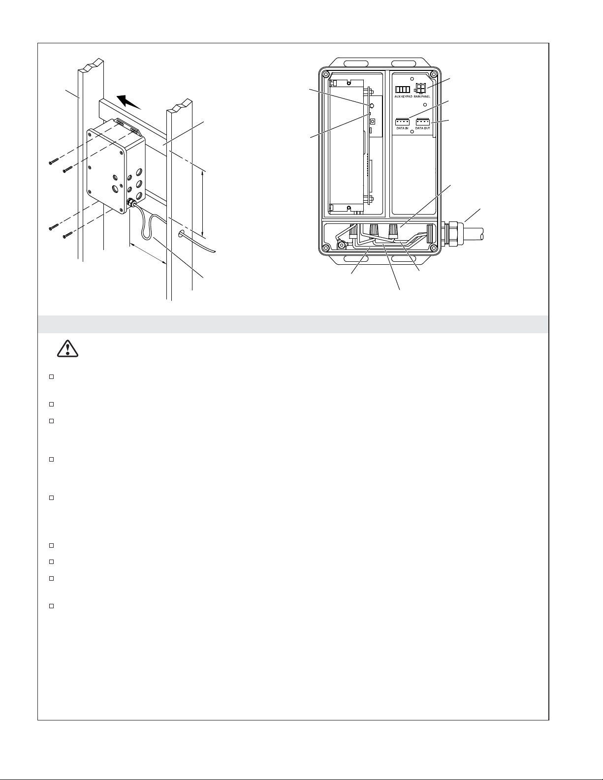
2x6
Position to allow room
for cable connection.
Mounting
Board
To Rain Panel
Fuse
DTV+ Data Cable
Not Used
LED
Wire Nut
8-1/4"
(210 mm)
6" (152 mm)
Min
Drip
Loop
Ground: Green or
Green with Yellow Stripe
Line: Black or Brown
Neutral: White or Blue with White
8. Install the Power Data Supply
DANGER: Risk of electrocution. Disconnect the electricity to the working area at the main breaker
panel before performing the installation steps for hardwiring.
The PDS is designed to fit within a service closet or 2x6 stud cavity with access panel. The PDS
must be within 25’ (7.62 m) of the lighted rain panel.
Install adequate bracing for mounting the PDS.
Route electrical wire to the service closet or 2x6 stud framing, within 24″ (610 mm) of the PDS.
Make sure the wire is in a position to reach the PDS where electrical connections can be made, and
allow enough wire to create a drip loop.
Position the PDS box within the closet or stud cavity to allow room for cover removal and
connecting the cables. If possible, connect the cables through the side holes rather than the cover
holes to ease cover removal for servicing.
Attach the PDS to structural framing or another secure surface using standard wood or drywall
screws (not supplied). Mounting boards may need to be installed between stud framing.
1/2" NPT
100-240 VAC
Make Hardwire Connections
Remove the PDS cover.
Feed electrical wire through the 1/2″ NPT hole into the power connection chamber of the PDS.
Using wire nuts, connect the Line (black or brown), Neutral (white or blue with white), and Ground
(green or green with yellow stripe) wires.
Following the electrical codes for internal wire bending, carefully tuck the wires into the PDS
housing. Ensure the wires will not be pinched when reinstalling the PDS cover.
Kohler Co. 11 1235394-2-A
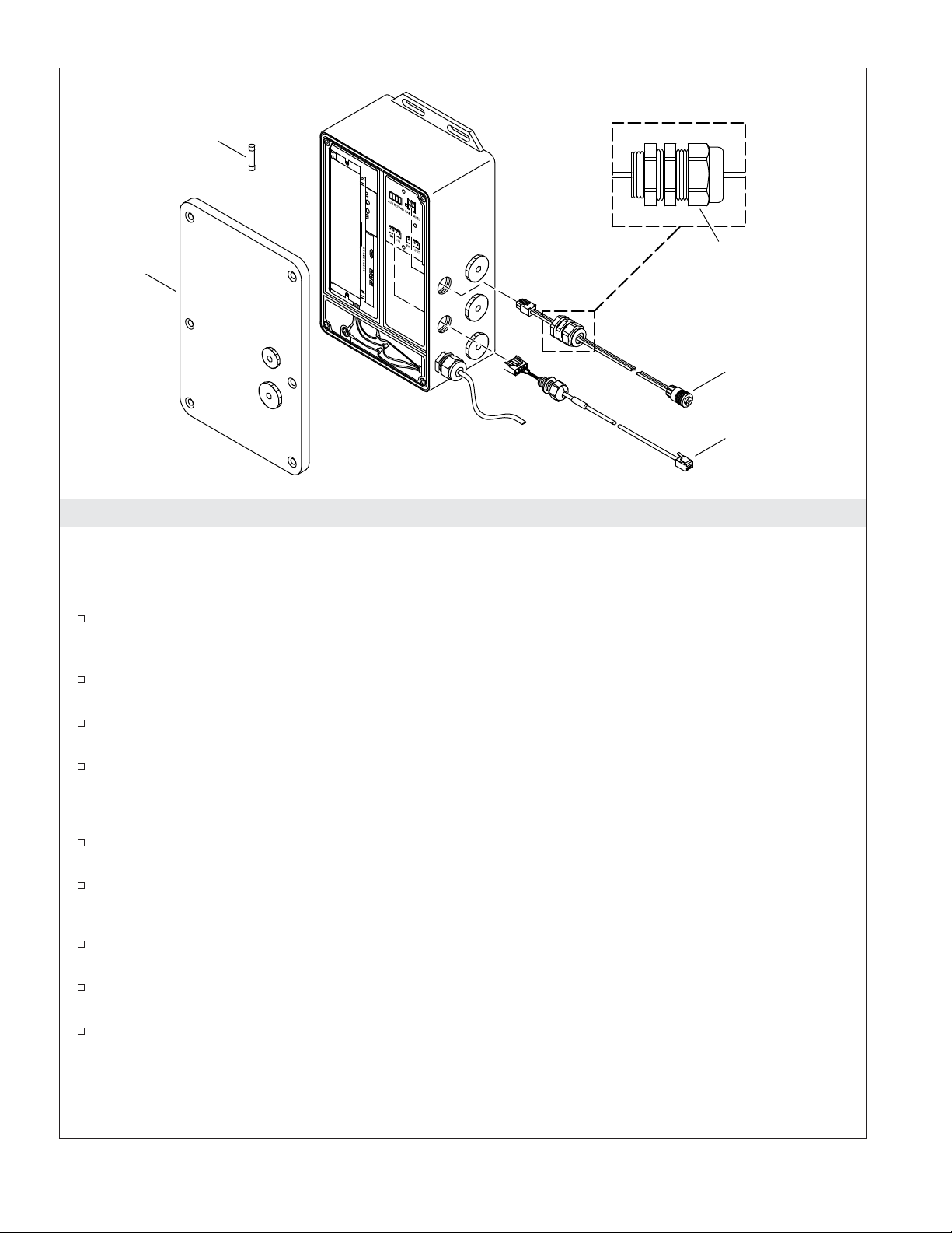
Fuse
Strain Relief Fitting
Access
Cover
Cap
Chroma
Power Cable
Data Cable
9. Connect the Cables
IMPORTANT! When possible, connect the cables through the side holes of the PDS rather than the cover
holes to ease cover removal for servicing.
NOTE: Make drip loops in all cables and cords.
Prepare cable ends for installation into the PDS by unthreading the strain relief cap and separating
the rubber stopper from the threaded body. This will prevent the cables from twisting while the
strain relief is threaded into the box.
Insert the chroma power cable into a 1/2” NPT hole and install into the “RAIN PANEL” connector
until it snaps together.
Insert the data cable into a 1/2” NPT hole and install into the “DATA IN” connector until it snaps
together.
Secure the cables and the electrical wire to the PDS using the watertight strain relief fittings. Thread
the fitting into the box, then slide the rubber stopper into the fitting. Tighten the cap to create a seal.
IMPORTANT! Verify all unused holes of the PDS box have plugs installed.
Verify all wires are tucked into the PDS housing and will not be pinched when securing the access
cover.
Reinstall the access cover. Do not overtighten.
Complete the Installation
If not already installed, install the K-99695 system controller according to the instructions packed
with the product.
Connect the data cable into one of the eight grouped component ports on the controller. Refer to the
″DTV+ System Layout″ section.
For information on system setup and operation, refer to the guide on the controller product page at
www.us.kohler.com.
Before Operating the System For the First Time:
Download and install the latest software for connected components. This may take an hour or more to
1235394-2-A 12 Kohler Co.
Connect the Cables (cont.)
complete based on system configuration and internet connection speed. Do not disconnect the power from
any components during software download and installation.
Care and Cleaning
For best results, keep the following in mind when caring for your KOHLER product:
•
Use a mild detergent such as liquid dishwashing soap and warm water for cleaning. Do not use
abrasive cleaners that may scratch or dull the surface.
•
Carefully read the cleaner product label to ensure the cleaner is safe for use on the material.
•
Always test your cleaning solution on an inconspicuous area before applying to the entire surface.
•
Do not allow cleaners to sit or soak on the surface.
•
Wipe surfaces clean and rinse completely with water immediately after cleaner application. Rinse
and dry any overspray that lands on nearby surfaces.
•
Use a soft, dampened sponge or cloth. Never use an abrasive material such as a brush or scouring
pad to clean surfaces.
For detailed cleaning information and products to consider, visit www.kohler.com/clean. To order Care &
Cleaning information, call 1-800-456-4537.
Troubleshooting
IMPORTANT! Turn off the power supply before performing any maintenance.
NOTE: For DTV+ system troubleshooting, refer to the guide on the K-99695 controller product page at
www.us.kohler.com.
NOTE: For service parts information, visit your product page at www.kohler.com/serviceparts.
This troubleshooting guide is for general aid only. For service and installation issues or concerns, call
1-800-4-KOHLER.
Troubleshooting Table
Symptoms Probable Cause Recommended Action
1. Rain panel does not
appear on the user
interface.
2. Rain panel appears on the
user interface but cannot
be selected.
3. Cannot remove cables
from PDS box.
A. No power to PDS. A. Turn off the power to the PDS and
B. Data cable connection to
controller is loose or damaged.
C. PDS fuse is blown. C. Replace the PDS fuse.
D. Controller is not assigning an
address to the PDS.
E. PDS failure. E. Contact a Kohler Co. Authorized
A. Chroma power cable is loose or
damaged.
B. PDS or lighted rain panel
failure.
A. Cables are twisting when
unthreading strain relief
connections.
remove the access cover. If the LED
light is not lit, the circuit breaker
may have been tripped. Reset the
circuit breaker. If the LED light is
still not lit, check hardwire
connections.
B. Check the cable connection, replace
cable if necessary.
D. Contact a Kohler Co. Authorized
Service Representative.
Service Representative.
A. Check the cable connection, replace
cable if necessary.
B. Contact a Kohler Co. Authorized
Service Representative.
A. Unthread strain relief cap only then
separate the rubber stopper from
the strain relief body. The strain
relief body will be free to unthread
from PDS box.
Kohler Co. 13 1235394-2-A
Troubleshooting (cont.)
Troubleshooting Table
Symptoms Probable Cause Recommended Action
4. Water is leaking from
around the sprayheads.
A. Nozzle membrane is not seated
properly.
A. Remove finished sprayface and
verify the nozzle membrane is
completely seated in the groove in
the sprayhead. Refer to the ″Install
the Trim″ section.
Warranty
KOHLER®Electronic Faucets, Valves and Controls
FIVE-YEAR LIMITED WARRANTY
Kohler Co. warrants that its electronic faucets, valves and controls will be free of defects in material and
workmanship during normal residential use for five years from the date the product is installed. This
warranty applies only to electronic faucets, valves and controls installed in the United States of America,
Canada and Mexico (″North America″).
If a defect is found in normal residential use, Kohler Co. will, at its election, repair, provide a replacement
part or product, or make appropriate adjustment where Kohler Co.’s inspection discloses any such defect.
Damage caused by accident, misuse, or abuse is not covered by this warranty. Improper care and cleaning
will void the warranty*. Proof of purchase (original sales receipt) must be provided to Kohler Co. with all
warranty claims. Kohler Co. is not responsible for labor charges, installation, or other incidental or
consequential costs other than those noted above. In no event shall the liability of Kohler Co. exceed the
purchase price of the faucet, valve or control.
If the electronic faucets, valves or controls are used commercially or are installed outside of North America,
Kohler Co. warrants that the faucet, valve or control will be free from defects in material and workmanship
for one (1) year from the date the product is installed, with all other terms of this warranty applying except
duration.
If you believe that you have a warranty claim, contact your Home Center, Dealer, Plumbing Contractor or
E-tailer. Please be sure to provide all pertinent information regarding your claim, including a complete
description of the problem, the product, model number, the date the product was purchased, from whom the
product was purchased and the installation date. Also include your original invoice. For other information,
or to obtain the name and address of the service and repair facility nearest you, write Kohler Co., Attn:
Customer Care Center, Kohler, Wisconsin 53044 USA, or by calling 1-800-4-KOHLER (1-800-456-4537) from
within the USA and Canada, and 001-800-456-4537 from within Mexico, or visit www.kohler.com within the
USA, www.ca.kohler.com from within Canada, or www.mx.kohler.com in Mexico.
THE FOREGOING WARRANTIES ARE IN LIEU OF ALL OTHER WARRANTIES, EXPRESS OR
IMPLIED, INCLUDING BUT NOT LIMITED TO THE IMPLIED WARRANTIES OF
MERCHANTABILITY AND FITNESS FOR A PARTICULAR PURPOSE.
KOHLER CO. AND/OR SELLER DISCLAIM ANY LIABILITY FOR SPECIAL, INCIDENTAL OR
CONSEQUENTIAL DAMAGES. Some states/provinces do not allow limitations on how long an implied
warranty lasts or the exclusion or limitation of such damages, so these limitations and exclusions may not
apply to you. This warranty gives the consumer specific legal rights. You may also have other rights that
vary from state/province to state/province. This warranty is to the original consumer purchaser only, and
excludes product damage due to installation error, product abuse, or product misuse, whether performed
by a contractor, service company, or the consumer.
This is Kohler Co.’s exclusive written warranty.
*Never use cleaners containing abrasive cleansers, ammonia, bleach, acids, waxes, alcohol, solvents or
other products not recommended for chrome. This will void the warranty.
1235394-2-A 14 Kohler Co.
Guide d’installation et d’entretien
Panneau de pluie éclairé pour DTV+
INSTRUCTIONS IMPORTANTES
AVERTISSEMENT: Lors de l’utilisation de produits électriques, toujours observer les
précautions de base, notamment:
DANGER: Risque d’électrocution. Déconnecter l’alimentation électrique pour la zone de travail au
niveau du disjoncteur principal avant d’exécuter les étapes d’installation pour le câblage.
AVERTISSEMENT: Risque de choc électrique. Raccorder uniquement à des circuits protégés par
un disjoncteur de fuite de terre (GFCI)*. Une mise à la terre est requise. L’appareil doit être installé
et mis à la terre par un représentant technique qualifié.
AVERTISSEMENT: Risque de choc électrique. Tout le câblage électrique doit être réalisé par un
électricien qualifié.
AVERTISSEMENT: Risque de choc électrique. Déconnecter l’alimentation électrique avant
d’effectuer un entretien.
AVERTISSEMENT: Risque de blessures ou d’endommagement du matériel. Lire toutes les
instructions avec attention avant de commencer l’installation.
AVIS: Respecter tous les codes de plomberie, d’électricité et de construction.
AVIS: Fournir un accès de service sans restrictions au dispositif d’alimentation de données d’alimentation
électrique (PDS).
*Hors de l’Amérique du Nord, ce dispositif peut être connu sous le nom de dispositif à courant résiduel
(RCD).
___________________________________________________________________________________________________
Fonctionnement avec DTV+
Pour connecter le panneau de pluie éclairé au système DTV+, le module de commande du système
K-99695 est requis.
Le câble de données fourni est utilisé pour connecter le dispositif PDS du panneau de pluie éclairé
au module de commande du système.
Se référer à la section ″Disposition du système DTV+″ dans ce guide.
Avant de faire fonctionner le système la première fois:
Télécharger et installer le dernier logiciel pour les composants connectés. Une heure ou plus peuvent être
nécessaires en fonction de la configuration du système et de la vitesse de connexion internet. Ne pas
déconnecter l’alimentation électrique des composants pendant le téléchargement et l’installation du
logiciel.
Spécifications
Température ambiante Max 104°F (40°C)
Humidité relative maximale 95% sans condensation
Kohler Co. Français-1 1235394-2-A
 Loading...