

Kohler K-21465T-G-0, S600G, K-21463T-G-0, K-21463T-XG-0 Installation And Homeowners Manual

Installation and Homeowners Guide
Veil Bathroom Heater S600G
S600G
K-21463T-G-0(Aircare)
K-21463T-XG-0
K-21465T-G-0
(Cloud)
KOHLER CHINA INVESTMENT CO., LTD NO.158, JIANG CHANG SAN ROAD,
1373009-T01-A
JING'AN DISTRICT, SHANGHAI, PRC POST CODE: 200436
( ) 158 200436
BEFORE YOU BEGIN
Please read these instructions carefully to familiarize
!
yourself with the required tools, materials, and installation
sequences. Follow the sections that pertain to your
particular installation. This will help you avoid costly
mistakes. In addition to proper installation, read all
operation and safety instructions.
All information in these instructions is based upon the
!
latest product information available at the time of
publication. Kohler China reserves the right to make
changes in product characteristics, packaging, or
availability at any time without notice.
These instructions contain important care, cleaning, and
!
warranty information -
consumer
This product complies with GB 4706.1-2005, GB4706.23-
!
.
please leave instructions for the
2007, GB 4706.27-2008, GB7000.1, GB7000.202 and
GB/T17743.
WARNING: Risk of electrical shock.
A licensed
electrician should make all electrical connections.
WARNING: Risk of electrical shock.
Connect only to
a circuit protected by a typical two-pole circuit breaker.
WARNING: Risk of electrical shock.
Disconnect
power before servicing.
!
,
!
!
!
GB 4706.1-2005 GB4706.23-2007 GB
4706.27-2008 GB7000.1 GB7000.202 GB/T17743
-
RECOMMENDED TOOLS AND MATERIALSRECOMMENDED TOOLS AND MATERIALS
!
Tape measure
!
Level
!
Screw driver
!
Connection wire
!
Wire cutter
!
Insulation tape
!
Bushing
!
Percussion Drill
!
Pen Knife
!
Wrench
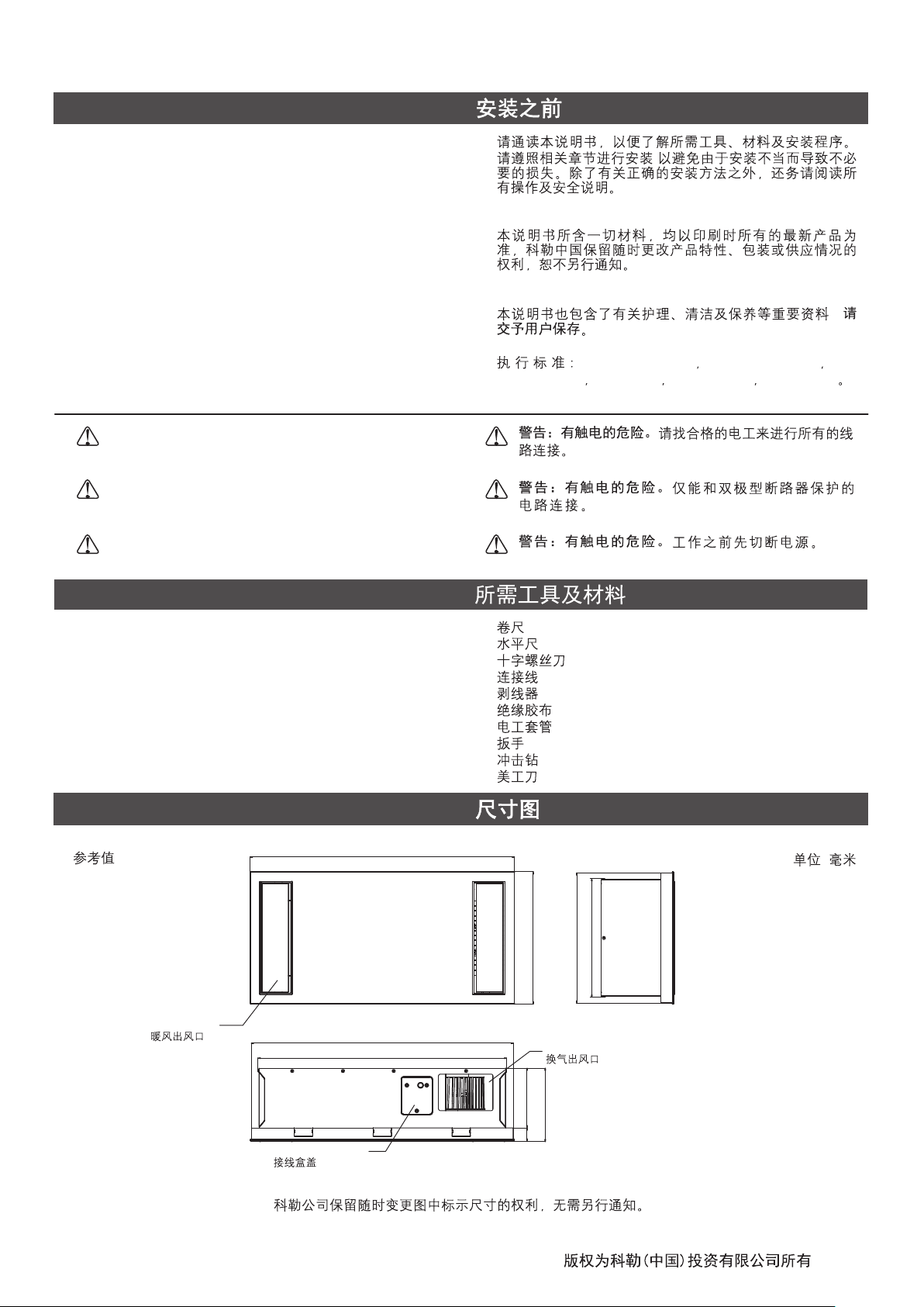
ROUGHING-IN
Reference Value
Hot Air Outlet
600
595
564
!
!
!
!
!
!
!
!
!
!
Unit: mm
:
269
295
300
Ventilation Outlet
1373009-T01-A
136
167
Junction Box Cover
31
Kohler reserves the right to change marked dimensions without prior notice.
-1-
©©Copyright Kohler China Investment Co., Ltd. 2018
2018
SPECIFICATIONS
Model
Voltage/Frequency
Rated Input Power
Heater Power
Fan Power
Dry Clothing Power
Ventilation Power
Air-care Power
Lighting Power
Ventilation Volume
Ventilation Noise
K-21463T-G-0/K-21463T-XG-0/
K-21465T-G-0
220V~/50Hz 220V~/50Hz
2750W 2750W
2731W 2731W
30W 30W
2600W(Hot)/60W(Cool)
33W 33W
31W(K-21463T-G-0/K-21463T-XG-0 )Only
19W 2 (108pcs 0.2W) 19W 2 (108 0.2W)
3
m /min
3.3 3.3m /min
43dB 43dB
IPX2 (Bathroom Heater) IPX2 ( )
Ingress Protection
IPX4 (Remote Control)
IP20 (LED)
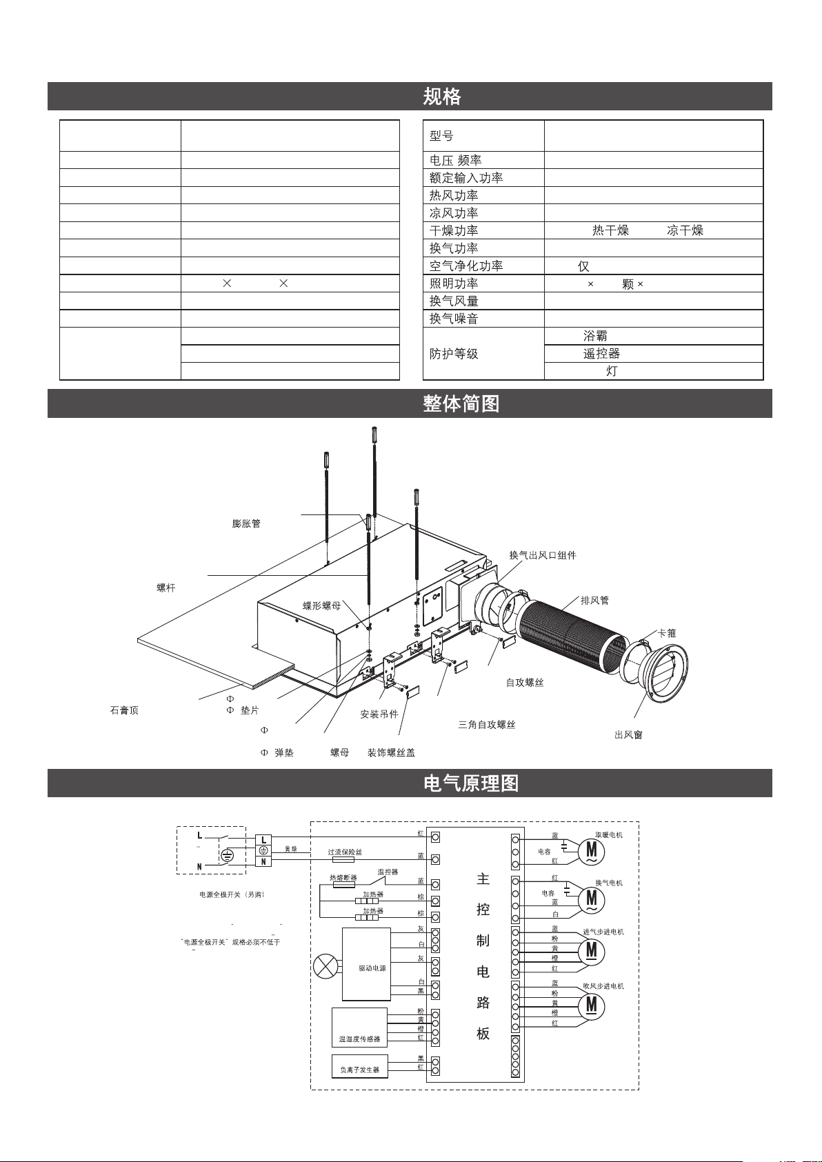
SIMPLIFIED DIAGRAM OF THE UNIT
Expansion Pipe
K-21463T-G-0/K-21463T-XG-0/
K-21465T-G-0
/
2600W( )/60W( )
31W( K-21463T-G-0/K-21463T-XG-0)
3
IPX4 ( )
IP20 (LED )
M6 Screw Rod
M6
Plasterboard Ceiling
WIRING DIAGRAM
K-21463T-G-0
220V
50Hz
ALL-POLE SWITCH (OPTIONAL)
THE RATE OF THE POWER SWITCH
MUST NOT BE LOWER THAN 250V 20A
250V 20A
6 Washer
6
Washer
M6 Butterfly Nut
M6
6 Spring
6
YELLOW/GREEN
/
Hanger
M6 Nut
M6
OVER CURRENT FUSE
THERMAL FUSE
HEATER 1 1
HEATER 2 2
LED POWER
LED
TEMPERATURE
AND HUMIDITY
SENSOR MODULE
ANION GENERATOR
BTP4*8 Triangular
Self Tapping Screw
BTP4*8
Decorative Screw Cover
RED
P1
BLUE
BLUE
GRAY
GRAY
PINK
RED
RED
P2
P3
P4
P5
CN4
CN14
CN11
CN12
CN5
THERMOSTAT
BROWN
BROWN
YELLOW
ORANGE
WHITE
WHITE
BLACK
BLACK
Ventilation Outlet Assy.
ST4.2*8 Self-tapping Screw
ST4.2*8
BLUE
CAPACITOR
MAIN CONTROL CIRCUIT BOARD
CN2
CN3
CN8
CN6
CN7
RED
RED
CAPACITOR
BLUE
WHITE
BLUE
PINK
YELLOW
ORANGE
RED
BLUE
PINK
YELLOW
ORANGE
RED
Air Exhaust Pipe
Clamp
Air Outlet Window
HOT MOTOR
VENT MOTOR
STEPPER MOTOR
STEPPER MOTOR
1373009-T01-A
-2-
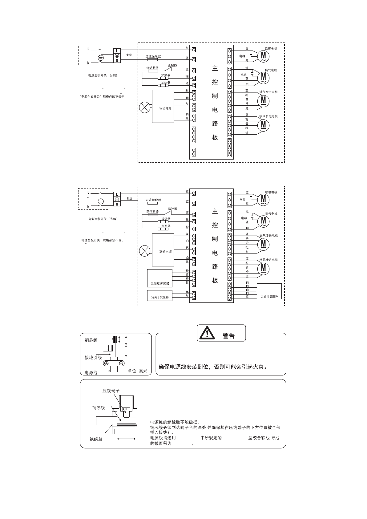
K-21465T-G-0
220V
50Hz
ALL-POLE SWITCH (OPTIONAL)
THE RATE OF THE POWER SWITCH
MUST NOT BE LOWER THAN 250V 20A
250V 20A
YELLOW/GREEN
K-21463T-XG-0
220V
50Hz
ALL-POLE SWITCH (OPTIONAL)
THE RATE OF THE POWER SWITCH
MUST NOT BE LOWER THAN 250V 20A
250V 20A
YELLOW/GREEN
OVER CURRENT FUSE
/
OVER CURRENT FUSE
/
THERMAL FUSE
HEATER 1 1
HEATER 2 2
LED POWER
LED
THERMAL FUSE
HEATER 1 1
HEATER 2 2
LED POWER
LED
TEMPERATURE
AND HUMIDITY
SENSOR MODULE
ANION GENERATOR
THERMOSTAT
BROWN
BROWN
THERMOSTAT
BROWN
BROWN
YELLOW
ORANGE
RED
BLUE
BLUE
GRAY
WHITE
GRAY
WHITE
BLACK
RED
BLUE
BLUE
GRAY
WHITE
GRAY
WHITE
BLACK
PINK
RED
BLACK
RED
P1
P2
P3
P4
P5
CN4
CN14
CN11
CN12
CN5
P1
P2
P3
P4
P5
CN4
CN14
CN11
CN12
CN5
MAIN CONTROL CIRCUIT BOARD
MAIN CONTROL CIRCUIT BOARD
CN2
CN3
CN8
CN6
CN7
CN2
CN3
CN8
CN6
CN7
BLUE
CAPACITOR
RED
RED
CAPACITOR
BLUE
WHITE
BLUE
PINK
YELLOW
ORANGE
RED
BLUE
PINK
YELLOW
ORANGE
RED
BLUE
CAPACITOR
RED
RED
CAPACITOR
BLUE
WHITE
BLUE
PINK
YELLOW
ORANGE
RED
BLUE
PINK
YELLOW
ORANGE
RED
WHITE
WHITE
WHITE
WHITE
RED
HOT MOTOR
VENT MOTOR
STEPPER MOTOR
STEPPER MOTOR
HOT MOTOR
VENT MOTOR
STEPPER MOTOR
STEPPER MOTOR
CLOUD
COMMUNICATION
ASSEMBLY
1373009-T01-A
Conductor
Earth
Power Cord
Terminal
Conductor
Insulation
WARNING
8
8
13 10
Make sure the power cord installed firmly,
otherwise it may catch fire.
(Unit: mm)
(: )
+
There's no risk of damage to the insulation of power cord.
+
Copper cord must be inserted into the pillar terminal hole, and make
sure all the cords under the terminal are inserted into the pillar
terminal completely.
Suggest using a power cord which with specification 60227 IEC 53
+
Model's powercord Specified in GB/T 5023.5 and with cross section
of 3X1.5mm .
+
+
8
+
2
,
GB/T 5023.5 60227 IEC 53 ,
3X1.5mm
2
-3-
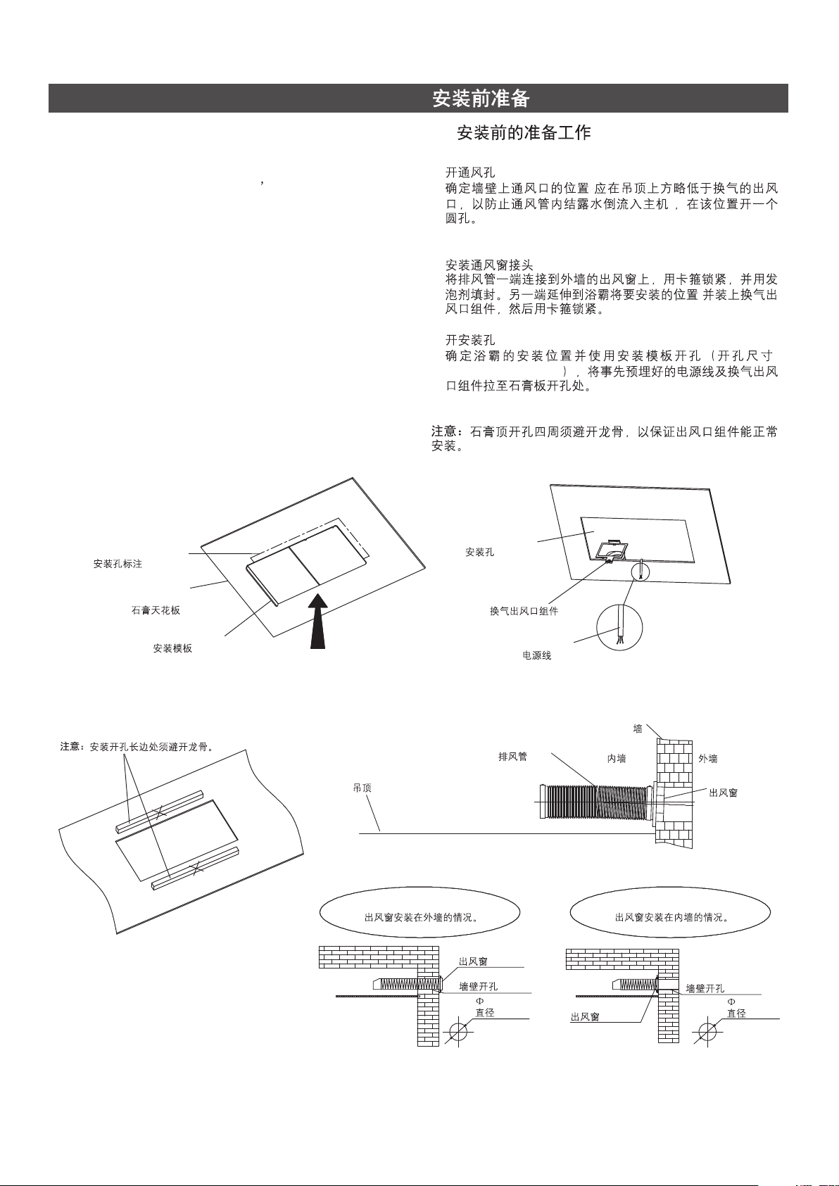
PREPARATIONS BEFORE INSTALLATION
A. Preparation before the installation A.
1. Open the hole of outlet window
Make sure that the outlet window s position (it should be
lower than the outlet of the bathroom heater to prevent the
water come back to the bathroom heater from the outlet
window), and open a round hole on the wall.
2. Outlet window installation
Sealing one end of the air exhaust pipe to the outlet
window on the wall with the clamp, and fix the other end to
ventilation outlet assembly with the clamp.
3. Make a Mounting Hole
Locate the position of the bathroom heater and make the
holes with the installation template (Hole Size 275 mm *
+5
575 mm ). Bring the power cords and ventilation outlet
0
+5
0
assembly to the hole edge on the plasterboard.
The keels should not be placed on the edges of the
Note:
installation holes to ensure that the ventilation outlet
assembly could be installed correctly.
Installation Hole Mark
1.
2.
3.
+5
275 mm * 575 mm
0
Installation Hole
(
)
,
+5
0
:
Plasterboard
Ceiling
Install Template
Please avoid the keels.Note:
Ceiling
Outer wall installing.
Ventilation
Outlet Assy.
Air Exhaust Pipe
Outlet Window
Hole on the Wall
120mm
120mm
Power cord
Inner Wall
Outlet Window
Wall
Outer Wall
Outlet Window
Inner wall installing.
Hole on the Wall
110mm
110mm
1373009-T01-A
-4-
 Loading...