

Page 1

Versamark DP5000 Series Printers
DP5120, DP5122 and DP5240
Installation Guide
Page 2

Page 3

Versamark DP5000 Series Printers
DP5120, DP5240, and DP5122
Installation Guide
Page 4

FCC Compliance Statement
This equipment has been tested and found to comply with the limits for a Class A digital device, pursuant to Part 15 of the FCC Rules. These
limits are designed to provide reasonable protection against harmful interference when the equipment is operated in a commercial environment.
This equipment generates, uses, and can radiate radio frequency energy and, if not installed and used in accordance with the instruction manual, may cause harmful interference to radio communications. Operation of this equipment in a residential area is likely to cause harmful interference, in which case the user will be required to correct the interference at his own expense.
Note: Good quality, shielded (braided shielded) cables must be used for the RS-232-C and Centronics interfaces.
Canadian EMI Compliance Statement
Le présent appareil numérique n’émet pas de bruits radioélectriques dépassant les limites applicables aux appareils numériques de la classe A
prescrites dans le Règlement sur le brouillage radioélectrique édicté par le ministère des Communications du Canada.
This digital apparatus does not exceed the Class A limits for radio noise emissions from digital apparatus set out in the Radio Interference Regulations of the Canadian Department of Communications.
EMI-CISPR 22/EN 55 022/CE Marking
Warning: This is a Class A product. In a domestic environment, this product may cause radio interference in which case the user may be
required to take adequate measures.
Versamark DP5000 Series Printers Printing Systems Installation Guide
Part Number Media Revision Date Description ECN
0114348-603 PDF 001 05/2008 Revision for DH5122 Printhead and the K4KB K8287
© Kodak, 2008. All rights reserved.
This document contains proprietary information of Eastman Kodak Company or its licensors and is their exclusive property. It may not be
reproduced without a written agreement from Eastman Kodak Company. No patent or other license is granted to this information.
The software described in this document is furnished under a license agreement. The software may not be used or copied except as provided in
the license agreement.
Eastman Kodak Company makes no warranty of any kind with regard to the contents of this document, including, but not limited to, the implied
warranties of merchantability and fitness for a particular purpose. Eastman Kodak Company shall not be liable for any errors or for
compensatory, incidental or consequential damages in connection with the furnishing, performance, or use of this document or the examples
contained herein. Information concerning products not manufactured by Eastman Kodak Company. is provided without warranty or
representation of any kind, and Eastman Kodak Company will not be liable for any damages resulting from the use of such information.
Kodak and Versamark are trademarks of Eastman Kodak Company.
0114348-603 05/2008
Page 5

Scope
This guide describes installation procedures for the following products:
•K
ODAK VERSAMARK DP5120 Printer (5120)
•K
ODAK VERSAMARK DP5240 printer (5240)
These printers have 1" printheads
•K
ODAK VERSAMARK DP5122 printer (5122)
This printer has a 2" printhead
•K
ODAK VERSAMARK CS150 System Controller.
The controller and up to three DP5000 series printers comprise a
printing system.
In this guide, Printing System refers specifically to a Kodak Versamark
CS150 system Controller (CS150), one or more DP5000 series printers,
and the standard enclosure (cabinet) supplied by Kodak.
This guide does not describe the Kodak Versamark 5000 Printer, Kodak
Versamark 5100 Printing System, Kodak Versamark 5242 Printing
System, or Kodak Versamark 5300 Printing System. Jetscape software
and Mailscape Version 3.96 (including the Read & Image option) are
described only as shipped in the dual controller configuration. See below.
Important: Availability of the Jetscape products described in this guide is limited.
Contact technical support before ordering or planning to purchase any
Jetscape product.
The procedures in this guide should be performed only by a Kodak Versamark field engineer, or a service technician trained by Kodak Versamark,
Inc.
Installation Guide 3
Page 6

Scope
!
WARNING
!
DANGER
Text Notations
Safety Notations
Note: Information that needs to be brought to the reader’s attention.
Caution: A situation where a mistake could result in the destruction of data or
This manual uses the following typographical conventions.
This style Refers to
Ready
go
ENTER
[NEXT] Buttons and lights on the printer operator panel.
Save Software command buttons and sections of dialog boxes,
File → Open
ALT+F1
ALT, TAB
xx,yy Variable in error messages and text.
jobfile.dat File names.
Text displayed by the software.
Anything you type, exactly as it appears, whether referenced
in text or at a prompt.
Special keys on the keyboard, such as enter, alt, and
spacebar.
such as group boxes, text boxes, and text fields.
A menu and a specific menu command.
Pressing more than one key at the same time.
Pressing more than one key in sequence.
The following definitions indicate safety precautions to the operator.
system-type damage.
A potential hazard that could result in serious injury or death.
An imminent hazard that will result in serious injury or death.
4 DP5000 Series Printers
Page 7

Scope
Service and Support
Technical equipment support is available 24 hours a day, 7 days a week.
Software and applications support is available 8:00 a.m. to 5:00 p.m.
EST/EDT, Monday through Friday.
Call for telephone or on-site technical support; to order parts or supplies;
to request documentation or product information.
Phone Fax
U.S.A., Canada, and
worldwide
Europe +41-21-806-0404 +41-21-806-1920
Asia/Pacific Rim +65-6744-6400 +65-6744-6700
Japan +81-03-5621-2220 +81-03-5621-6195
Updated service
information
Customer support customer@kodakversamark.com
http://www.kodakversamark.com
+1-800-472-4839
+1-937-259-3739
+1-937-259-3808
Installation Guide 5
Page 8

Page 9

Contents
Chapter 1. Preparation
Safety Precautions............................................................................................ 1-1
Lifting Technique........................................................................................ 1-1
Electrical Safety ......................................................................................... 1- 1
Fluidic Safety.............................................................................................. 1-2
Required Tools ................................................................................................. 1- 2
Chapter 2. Unpacking
Printer ............................................................................................................... 2-1
Removing Packaging ................................................................................. 2- 2
Printer Inventory......................................................................................... 2- 3
Moving the Printer ...................................................................................... 2-4
Printing System................................................................................................. 2- 5
Removing System Packaging .................................................................... 2-5
System Inventory ....................................................................................... 2- 8
System Unpacking ................................................................................... 2- 10
Accessories .............................................................................................. 2- 11
Printheads....................................................................................................... 2-12
DH5120 Printhead.................................................................................... 2-13
DH5240 Printhead.................................................................................... 2-14
DH5122 Printhead.................................................................................... 2-15
Chapter 3. Printer Installation
Printer Positioning............................................................................................. 3-1
Printer Stand Installation ............................................................................ 3- 1
Customer-Supplied Support....................................................................... 3- 3
Fluid Container Installation ............................................................................... 3-4
Internal ....................................................................................................... 3-4
Ink Bottle.............................................................................................. 3-5
Replenisher Bottle ............................................................................... 3-6
External ...................................................................................................... 3- 7
Voltage Selection.............................................................................................. 3-8
Printer Connections .......................................................................................... 3- 9
Printer Power ........................................................................................... 3- 11
Ethernet.................................................................................................... 3- 12
RS 232 (Serial)......................................................................................... 3- 13
Centronics (Parallel)................................................................................. 3- 14
Control I/O ................................................................................................ 3- 15
Tach and Cue........................................................................................... 3- 16
K4K .......................................................................................................... 3-17
Sort / Stop ................................................................................................ 3-18
Chapter 4. System Installation
Enclosure Positioning ....................................................................................... 4- 1
Controller Positioning........................................................................................ 4-2
System Connections......................................................................................... 4-4
Cabinet Connections .................................................................................. 4- 4
System Power...................................................................................... 4- 4
Installation Guide 1
Page 10

Contents
External Tach and Cue ........................................................................ 4-5
Controller Connections ............................................................................... 4- 5
Data Cable ........................................................................................... 4 - 6
Keyboard and Mouse ........................................................................... 4 - 7
Monitor Interface .................................................................................. 4- 7
Power Cables ....................................................................................... 4- 8
Installing Software............................................................................................. 4-8
Chapter 5. Printhead Installation
DH5120 Printhead............................................................................................. 5- 2
DH5240 Printhead............................................................................................. 5- 3
DH5122 Printhead............................................................................................. 5- 4
Chapter 6. Testing
Electronics Tests............................................................................................... 6-1
Fluidics Tests .................................................................................................... 6 - 2
System Tests .................................................................................................... 6 - 3
Printhead Adjustment........................................................................................ 6 -5
Phase Adjustment....................................................................................... 6-5
Adjusting Voltage........................................................................................ 6 - 6
Appendix A. Installation Checklists
Printer Checklist ............................................................................................... A- 1
Printhead Checklist .......................................................................................... A-1
Printing System Checklist ................................................................................ A-2
Appendix B. Tach and Cue Wiring
Appendix C. Site Requirements
Electrical Requirements ................................................................................... C- 1
Environmental Requirements........................................................................... C- 2
Space Requirements........................................................................................ C -2
2 DP5000 Series Printers
Page 11

Figures
Figure 2.1 Printer on shipping pallet ......................................................... 2 - 2
Figure 2.2 Printing system pallet, shrink wrap removed ........................... 2 - 5
Figure 2.3 Printing system box, ready for unpacking ................................ 2 - 6
Figure 2.4 Printing system box, side walls removed ................................. 2 - 6
Figure 2.5 DH5120 printhead, capsule inside inner box ......................... 2 - 13
Figure 2.6 DH5240 printhead, capsule inside inner box ......................... 2 - 14
Figure 2.7 DH5122 printhead.................................................................. 2 - 15
Figure 3.1 Printer on stand ....................................................................... 3 - 2
Figure 3.2 Screw locations, printer stand.................................................. 3 - 2
Figure 3.3 Printer positioning limits, height and distance.......................... 3 - 3
Figure 3.4 Ink bottle compartment, DP5122 printer .................................. 3 - 5
Figure 3.5 External 20-liter cubitainer fluid supply .................................... 3 - 7
Figure 3.6 External 55-gallon supply containers ....................................... 3 - 8
Figure 3.7 Voltage selector switch cover .................................................. 3 - 8
Figure 3.8 Fuse removal, circuit breaker switch ....................................... 3 - 9
Figure 3.9 Voltage selector switch, DP5120 and DP5240 ........................ 3 - 9
Figure 3.10 Connectors, printer back panel.............................................. 3 - 10
Figure 3.11 Power cord connector, printer back panel ............................. 3 - 11
Figure 3.12 Ethernet connection, printer back panel ................................ 3 - 12
Figure 3.13 RS 232 (serial) connection, printer back panel...................... 3 - 13
Figure 3.14 Parallel data connection, printer ............................................ 3 - 14
Figure 3.15 Control I/O connection, printer back panel ............................ 3 - 15
Figure 3.16 Tach and cue connection....................................................... 3 - 16
Figure 3.17 K4K connection, DP5240....................................................... 3 - 17
Figure 3.18 Connector wiring, relay contact cable.................................... 3 - 19
Figure 3.19 Sort relay cable connection, printer back panel..................... 3 - 19
Figure 4.1 Cabinet, ready for positioning .................................................. 4 - 1
Figure 4.2 Enclosure ready for positioning ............................................... 4 - 2
Figure 4.3 Controller components on system enclosure........................... 4 - 3
Figure 4.4 Hardware and cable kit cables................................................. 4 - 3
Figure 4.5 Power cord connection, printing system .................................. 4 - 5
Figure 4.6 Controller PC connectors, back panel ..................................... 4 - 6
Figure 4.7 Controller data, keyboard and mouse cables .......................... 4 - 7
Figure 4.8 Video connection, controller PC .............................................. 4 - 7
Figure 4.9 PC and monitor power cables.................................................. 4 - 8
Figure 5.1 DH5120 printhead, in shipping container................................. 5 - 2
Figure 5.2 DH5240 printhead, in shipping container................................. 5 - 3
Figure 5.3 DH5122 printhead in shipping container.................................. 5 - 4
Figure 6.1 Missing spots or bands of print ................................................ 6 - 5
Figure 6.2 Dark defect, defines low end of print window .......................... 6 - 7
Figure B.1 Tach and cue wiring, DP5000 series printers .......................... B - 1
Figure C.1 DH5122 printhead dimensions ............................................... C - 3
Installation Guide 3
Page 12

Contents
Figures
4 DP5000 Series Printers
Page 13

Tables
Table 2.1 Printer model shipping numbers............................................. 2-3
Table 2.2 Components, typical printer shipment .................................... 2- 3
Table 2.3 Printing system models and shipping numbers ...................... 2- 8
Table 2.4 Components, typical printing system shipment ...................... 2 -9
Table 2.5 System shipment contents.................................................... 2- 11
Table 2.6 Printhead models and shipping numbers ............................. 2 -12
Table 3.1 Fluid part numbers, DP5000 series printers ........................... 3-4
Table 3.2 Relay contact cable wiring .................................................... 3-18
Table 5.1 Printhead container contents, DH5120 printhead................... 5-2
Table 5.2 Printhead container contents, DH5240 printhead................... 5-3
Table 5.3 Printhead box contents, DH5122............................................ 5-4
Table C.1 Electrical requirements .......................................................... C - 1
Table C.2 Environmental requirements .................................................. C-2
Table C.3 Space requirements............................................................... C - 2
Installation Guide 3
Page 14

Contents
Tables
4 DP5000 Series Printers
Page 15

Safety Precautions
Chapter 1. Preparation
This chapter describes the requirements for an installation, and the
following procedures and guidelines:
• Safety precautions
• Required tools.
Read all procedures thoroughly prior to installation. Follow any warnings
and special instructions that appear in the manuals and on labels affixed
to the printer and system components to avoid physical harm to you or the
components.
Observe the following safety precautions during all installation
procedures.
Lifting Technique
Apply the following guidelines to moving components.
• Use two persons to lift the printer box, the printing system enclosure,
or any large component, or any box that exceeds 50 lbs (27 kg).
• Lift carefully using the legs and not the back (see OSHA standards).
Electrical Safety
Apply the following guidelines when working with any internal component
of the printer, or around any power source.
• Observe all precautions regarding high voltage.
• Use proper procedures for handling electrical equipment (see OSHA
standards).
• Observe all precautions in warning and caution notations (see
”Scope”).
• Observe proper electro-static discharge (ESD) precautions.
• Use proper voltage levels, and observe proper grounding techniques.
• Observe all precautions for working around electrical devices that
remain charged after input power is cut off.
Installation Guide 1-1
Page 16

Chapter 1. Preparation
Required Tools
Required Tools
Fluidic Safety
Apply the following guidelines when handling ink, replenisher, or purge
fluid.
• Read the Material Safety Data Sheet (MSDS) for a fluid before
handling it, and follow all instructions in the documentation shipped
with the fluid.
• Clean up any spill immediately.
• Wear approved protective equipment (see OSHA standards).
• Dispose of hazardous material properly (see OSHA standards and all
local, state, and Federal regulations that apply).
Before starting the installation, check that you have the following required
tools and equipment.
• Standard FE took kit (0177490).
• ESD protection kit (0110094).
The following kits are recommended, but not required.
• DTR test kit (0178399)
• DP5120/DP5240 flush kit (0177491).
1-2 DP5000 Series Printers
Page 17

Printer
Chapter 2. Unpacking
This chapter describes how to unpack the following components:
• Printer
• Printing system
• Printheads.
To ensure that you complete all steps of these procedures use the
checklists in “Appendix A”.
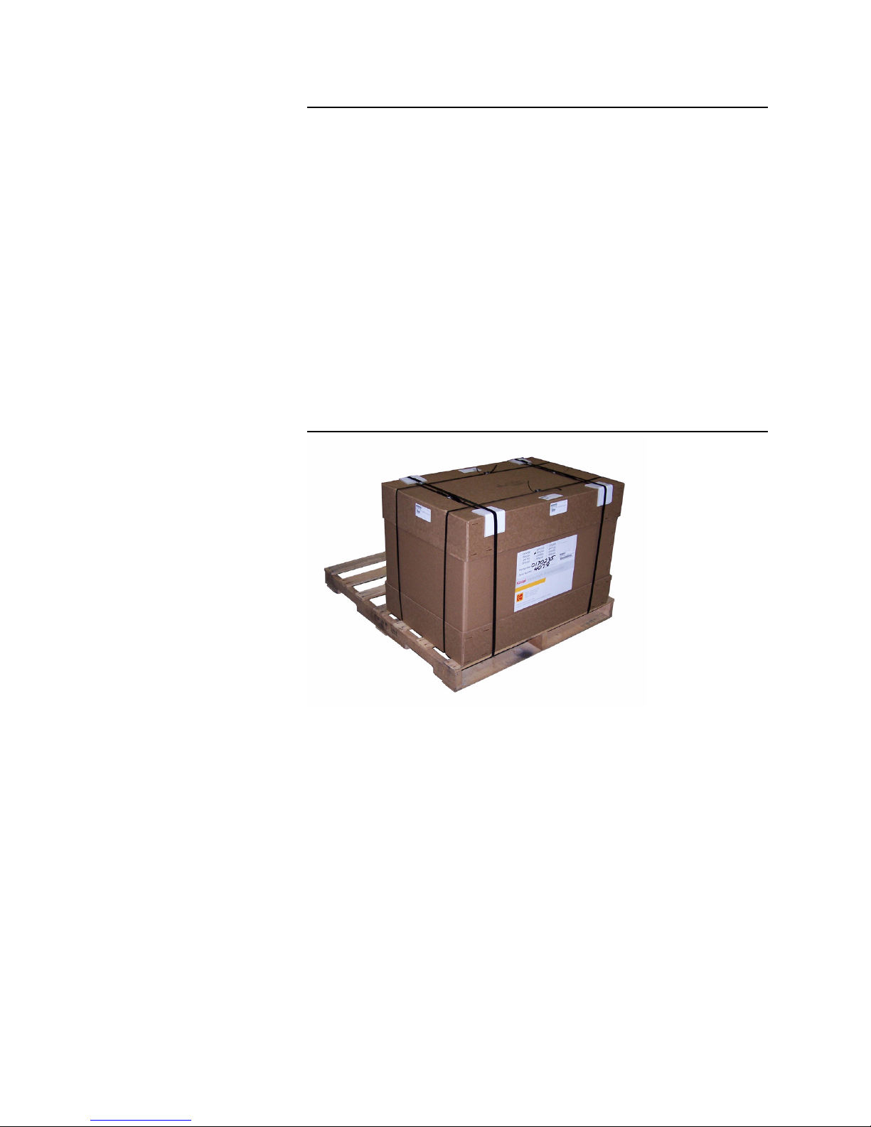
The printer components are shrink-wrapped to a shipping pallet (see
Figure 2.1). Depending on the contents of the product order, other boxes
may be shipped on the same pallet.
Installation Guide 2-1
Page 18
Chapter 2. Unpacking
Printer
Removing Packaging
Use the following procedure to remove the pallet packaging.
1. Use a forklift or hand truck to move the pallet as close as possible to
the final location intended for the printer.
2. Position the pallet where there is 3 ft. (1 m) of clear working space on
all four sides.
3. Cut the shrink-wrap and remove it from the pallet.
Caution: Do not cut into the boxes. Use a box knife or other short-bladed tool and
cut where pallet contents do not touch the shrink wrap.
4. Remove the smaller boxes from the pallet and set them aside for later
unpacking.
Note: A typical printer shipment includes three extra boxes (see “Printer
Inventory”). Figure 2.1 shows the pallet with the shrink wrap and smaller
boxes removed.
Figure 2.1 Printer on shipping pallet
Note: Set the accessories box aside for later unpacking.
Note: Leave the packaging on the printhead housing at the end of the umbilical.
2-2 DP5000 Series Printers
5. Cut the bands on the printer box.
6. Remove the box lid.
7. Remove the printer accessories box from inside the printer box.
8. Cut open the end (short side) of the box at the back of the printer.
a. Access the back of the printer where the handle is located.
9. Fold down or tear off the cut side of the box.
10. Remove all the packaging from the pallet and the area around the
printer.
11. Continue with the shipment inventory.
Page 19
Chapter 2. Unpacking
Printer Inventory
Before starting to unpack the shipment, use the following procedure to
inventory its contents.
1. Check the type of printer identified by the number on the printer box
(see Table 2.1).
Table 2.1 Printer model shipping numbers
Part Number Printer Model and Options
0170151 KODAK VERSAMARK DP5120 DK GREY PRINTER, 12' UMBILICAL
0170154 KODAK VERSAMARK DP5240 DK GREY PRINTER, 12' UMBILICAL
0170155 KODAK VERSAMARK DP5240 DK GREY PRINTER, 24' UMBILICAL
0170156 KODAK VERSAMARK DP5240 DK GREY PRINTER, 24' UMBILICAL, K4K
0170159 KODAK VERSAMARK DP5120 DK GREY PRINTER, 24' UMBILICAL
0170161 KODAK VERSAMARK DP5120 DK GREY PRINTER, 24' UMBILICAL, K4K
0170162 KODAK VERSAMARK DP5122 DK GREY PRINTER, 12' UMBILICAL
0170163 KODAK VERSAMARK DP5122 DK GREY PRINTER, 24' UMBILICAL
0170168 KODAK VERSAMARK DP5120 DK GREY PRINTER, 12' UMBILICAL,W/TRANSFORMER
0170175 KODAK VERSAMARK DP5120 DK GRAY PRINTER, 12' UMBILICAL, K4K MINUS BOARD
0170176 KODAK VERSAMARK DP5240 DK GREY PRINTER, 12' UMBILICAL, HI MEMORY
Printer
2. Check the pallet contents against the packing slip (or copy of the
order acknowledgement form). Note any short or over shipments.
Table 2.2 lists the contents of a typical printer shipment. The printer,
printheads, base cabinet, and printhead mount are individually boxed.
All other items are shipped together in one accessories box. A
shipment can include additional components, most commonly ink and
extra printheads.
Table 2.2 Components, typical printer shipment
Part Number Description Quantity Location
0170162 KODAK VERSAMARK DP5122 DK GREY PRINTER, 12'
UMBILICAL
0100238-026 CORD-PWR 16AWG 13A 125V 7.5FT 1
0187976 PRINTER HARDWARE KIT 1 Inside printer box
0188200 PRINTHEAD 2
0177489 INSTALLATION KIT 1
0188398 MANUALS KIT-DP5122 PRINTER 1
0187412 CATCH PAN-SERVICE (1"/2") 1
0187887 BASE CABINET ASSEMBLY DK GREY 1 Separate box
0187733 PRINTHEAD MOUNT - STAND ASSY 1
1 Printer box
Inside printer box
Separate box
Accessories box
Separate box
1
2
3
4
1. A domestic (US), European or Japanese power cord is shipped depending on the shipment destination.
2. Two printheads are shipped with a DP5240 or DP5122 printer; only one printhead is shipped with a DP5120 printer.
3. Labeled with the printer model part number or the printer serial number.
4. Shipped on a separate pallet if necessary. An alternate is the LABEL BASE 2" PRINTHEAD MOUNT (0187734).
Installation Guide 2-3
Page 20

Chapter 2. Unpacking
Printer
Moving the Printer
Use the following procedure to move the printer off of the shipping pallet:
1. Cut the straps securing the printing system box to the pallet.
2. Remove the box lid.
3. Remove any loose packing material from inside the printer box.
Note: Manuals, cables, software and other small items are packed inside the
installation kit box. If only a printer and printheads were shipped, these
items will be shipped inside a separate box.
4. Cut open the end of the box next to the umbilical connection.
5. Fold down the cut box wall.
6. Uncoil the umbilical and lay it on top of the printer, or to one side.
7. Make sure the umbilical does not obstruct moving the printer.
Caution: The following steps require two persons.
8. If two persons are available, work together to lift the printer out of its
packing base and set it on a level surface.
9. If only one person is available, pull the printer slowly out of the box
and off the pallet.
Caution: Do not let the printer drop or tip over.
10. Coil the umbilical around the umbilical hanger on the printer rear
panel and nest the printhead housing in the coils.
11. Continue with “System Unpacking”.
2-4 DP5000 Series Printers
Page 21

Printing System
Ramps
Controller,
installation kit,
and printhead boxes
Chapter 2. Unpacking
Printing System
A printing system is shipped strapped to a shipping pallet (see Figure
2.2). Unpacking a system consists of the following procedures:
• Removing system packaging
• System inventory
• System unpacking
• Accessories.
Removing System Packaging
The components of a standard printing system components are shipped
in four or more boxes packed on one pallet. The number of pallets and
their contents can vary depending on the type of system ordered. Use the
following procedure to unpack the system.
1. Move the shipping pallet as close as possible to the final location
intended for the printing system.
Note: Use a forklift or hand truck to move the pallet.
2. Position the pallet where there is 3 ft. (1 m) of clear, working space on
all four sides.
3. Cut the shrink-wrap and remove it from the pallet (see Figure 2.2).
Caution: Do not cut into the boxes. Use a box knife or other short-bladed tool and
cut where pallet contents do not touch the shrink wrap.
Figure 2.2 Printing system pallet, shrink wrap removed
4. Remove the two wooden ramps from the shipping pallet and set them
aside for later use.
5. Remove all boxes except the printing system box from the pallet. Set
these boxes aside for later unpacking.
6. Cut the bands securing the printing system box lid (see Figure 2.3).
Installation Guide 2-5
Page 22

Chapter 2. Unpacking
Ramp diagram
Box lid
Bands
Cutouts
for ramps
Plastic cover
Printing System
Figure 2.3 Printing system box, ready for unpacking
7. Remove the box lid.
8. Remove and discard the cut bands.
9. Remove the side walls of the box (see Figure 2.4).
Figure 2.4 Printing system box, side walls removed
2-6 DP5000 Series Printers
10. Remove the plastic cover from the printing system.
11. Remove the packing material from around the base of the printing
system enclosure on the short side of the box next to the two cutouts
in the pallet rim for the ramps.
12. Remove the screws taped to the ramps.
13. Secure the ramps to the pallet with the screws supplied. Use the predrilled holes on the pallet frame at each cutout.
Page 23

Chapter 2. Unpacking
Printing System
14. Unlock the printing system enclosure (cabinet) caster locks.
Caution: The following steps should be done by two persons. If you are alone,
exercise additional caution.
15. If two persons are available, tilt the cabinet slightly toward either of its
long sides, and then pull any packing material under it out. If you are
alone, cut away any packing material underneath the cabinet that
blocks the casters
16. Roll the cabinet down the ramp and onto the floor.
17. Stop the cabinet when it is level with all four casters on the floor and
lock the casters.
Hint: It is easier and safer to pull the cabinet down the ramp rather than to push
it down. The printer weighs approximately 100 lbs (45 kg), and pulling the
cabinet down allows you to guide and slow it as it moves down the ramps.
Caution: Do not let the cabinet roll free or tip more than 20 degrees as it moves
down the ramps.
18. Remove any packaging material from inside the cabinet.
19. Remove the umbilical and printhead housing from inside the cabinet
and coil the umbilical on top of the cabinet and nest the printhead
housing within the coils.
Note: Leave the protective packaging on the printhead housing. This packaging
should not be removed until you perform the printhead installation (see
“Printheads”).
20. Roll the cabinet to where the printing system is to be installed.
21. Continue with the printing system installation procedure (see “System
Inventory”).
Installation Guide 2-7
Page 24

Chapter 2. Unpacking
Printing System
System Inventory
Before starting to unpack the printing system enclosure, use the following
procedure to inventory its contents.
1. Check the type of printing system identified by the number on the
printer box (see Table 2.3).
Table 2.3 Printing system models and shipping numbers
Part Number Printer Model and Options
0170152 KODAK VERSAMARK DP5120 DK GREY SYSTEM, NO MTU, 12' UMBILICAL, JETSCAPE
0170153 KODAK VERSAMARK DP5120 DK GREY SYSTEM, NO MTU, 12' UMBILICAL, CS150
0170157 KODAK VERSAMARK DP5240 DK GREY SYSTEM, NO MTU, 12' UMBILICAL, JETSCAPE
0170158 KODAK VERSAMARK DP5240 DK GREY SYSTEM, NO MTU, 12' UMBILICAL, CS150
0170160 KODAK VERSAMARK DP5120 DK GREY SYSTEM, NO MTU, 24' UMBILICAL, JETSCAPE
0170164 KODAK VERSAMARK DP5122 DK GREY SYSTEM, NO MTU, DUAL CONTROLLER, 12' UMBILICAL
0170165 KODAK VERSAMARK DP5122 DK GREY SYSTEM, NO MTU, DUAL CONTROLLER, 24' UMBILICAL
0170166 KODAK VERSAMARK DP5122 DK GREY SYSTEM, NO MTU, DUAL CONTROLLER, 12' UMBILICAL,
0170167 KODAK VERSAMARK DP5122 DK GREY SYSTEM, NO MTU, DUAL CONTROLLER, 24' UMBILICAL,
0170169 KODAK VERSAMARK DP5240 DK GRAY SYSTEM, NO MTU, 12' UMBILICAL, DUAL CONTROLLER
0170170 KODAK VERSAMARK DP5120 DK GRAY SYSTEM, NO MTU, 24' UMBILICAL, CS150, K4K
0170171 KODAK VERSAMARK DP5120 DK. GREY SYSTEM, MTU,12' UMBILICAL, JETSCAPE
0170172 KODAK VERSAMARK DP5120 DK. GREY SYSTEM, NO MTU,12' UMBILICAL, DUAL CONTROLLER
0170173 KODAK VERSAMARK DP5122 DK GRAY SYSTEM, NO MTU, DUAL CONTROLLER, 12' UMBILICAL, w/
MPI
MPI
TRANSFORMER
2-8 DP5000 Series Printers
Page 25

2. Check the pallet contents against the packing slip (or copy of the
order acknowledgement form). Note any short or over shipments.
Table 2.4 lists the contents of a typical system shipment. The system
cabinet, printheads, printhead mount, and are individually boxed. All
other items are shipped together in one accessories box labeled with
the shipment part number or the printer serial number. A shipment
can include additional components, most commonly ink and extra
printheads.
Table 2.4 Components, typical printing system shipment
Chapter 2. Unpacking
Printing System
Part
Number
Description
0170165 KODAK VERSAMARK DP5122 DK GREY SYSTEM, NO MTU, DUAL
CONTROLLER, 24' UMBILICAL
0100238-
CORD-PWR 16AWG 13A 125V 7.5FT 1
026
0185072
DUAL CONTROLLER PC KIT
2
Quantity
1
Location
1
On pallet
Accessories box
1 Separate box
- MONITOR 1 Separate box
0188200
PH-2"/120 DPI PKD
3
2 Separate box
0177489 INSTALLATION KIT 1
0188399 MANUALS KIT-DP5122 PRINTING SYSTEM 1
0187412 CATCH PAN-SERVICE (1"/2") 1
Accessories box
0177184 TACH KIT-BELT DRIVEN TRANSPORT 1
0175780 CUE ASSY (6 FT) W/PKG 1
0187887 BASE CABINET ASSEMBLY DK GREY 1 Separate box
0187734 LABEL BASE 2" PRINTHEAD MOUNT 1
-
1. Quantity if shipped on the printer pallet, or location if shipped separately.
2. This kit is the Pioneer PC (chassis and documentation).
3. Two printheads are shipped with a DP5240 or DP5122 printer, one with a DP5120 printer.
4. Shipped on a separate pallet. An alternate is the PRINTHEAD MOUNT - STAND ASSY (0187733).
5. The two wooden ramps are taped together with the screws taped to them.
RAMPS (W/ SCREWS)
5
1 On top of boxes
Separate box
4
Installation Guide 2-9
Page 26

Chapter 2. Unpacking
Printing System
System Unpacking
Use the following procedure to unpack the system controller (host) and
other components of a printing system.
1. Move all the boxes to the location where the system is to be installed.
2. Place the monitor and computer (system controller PC) boxes by the
cabinet. They are unpacked when installed (see Chapter 4, “System
Installation”).
3. Unpack the PC peripherals box; it contains the following items:
• Keyboard
•Mouse
• PC manuals
• PC cables.
4. Set the PC peripherals aside until ready to begin the system
installation.
5. Unpack the system accessories box. The following contains the
system components:
• Manuals set (up to six books)
•Cables
• Power cord kit
• Installation kit.
6. If options or accessories were included in the shipment, unpack those
items (see “Accessories”). Otherwise, continue with the installation
procedure (see “Printing System”).
2-10 DP5000 Series Printers
Page 27

Accessories
Use the following general procedure as a guideline for unpacking any
accessories included in the shipment.
1. Use the shipping numbers on the boxes to identify which options are
Table 2.5 System shipment contents
Chapter 2. Unpacking
Printing System
part of the shipment (see Table 2.5).
Part Number Description Notes / Function
0175834 BASE CABINET ASSY Rollaround stand - DP5120/
0187887 BASE CABINET ASSEMBLY DK GRAY Printer stand - DP5122
0176498 PRINTHEAD MOUNT STAND Rollaround stand - DP5120/
0187733 PRINTHEAD MOUNT 2" STAND ASSY Rollaround stand for DP5122
0177499 CATCH PAN ASSY For DP5120 and DP5240
0187412 1"/2" SERVICE CATCHPAN ASSEMBLY For DP5122
0176499 LABEL BASE PRINTHEAD MOUNT For DP5120 and DP5240
0187734 LABEL BASE 2" PRINTHEAD MOUNT For DP5122
0182591 RESTRAINT - UMBILICAL Imaging tower option
0178202 PRINTHEAD MOUNT ASSY Transport option
0104009-211 POWER CONDITIONER 120VAC IN/OUT
0104009-212 POWER CONDITIONER 230VAC IN 120VAC
OUT
0180088 REMOTE OPERATOR PANEL 0113455
0187611 CS150 MULTI-PRINTER KIT H/W Hardware and software
0187612 MULTI-PRINTER INTERFACE JETSCAPE Hardware and software
0179993 PRECISION MT 1 INCH PH ASSY Adapter for 4" printhead
0180117 NON-STITCH MT 1 INCH PH ASSY Adapter for 4" printhead
DP5240
DP5240
System option
mount
mount
Reference
Document
Vendor document
0113754
Vendor document
0113754
Vendor document
01140540186038 CS150 MULTI-PRINTER KIT S/W Software
0113757
0113758
2. Unpack each accessory box and locate the documentation.
3. Refer to installation instructions listed in Table 2.5 for detailed
information on each component.
4. For software and memory options, see the DP5000 Series software
Installation Guide (0114083).
5. Continue with the printhead unpacking procedure.
Installation Guide 2 - 11
Page 28

Chapter 2. Unpacking
Printheads
Printheads
Each DP5000 series printhead has a different part number and is shipped
in a separate box (see Table 2.6). The following sections identify the
printheads and provide general installation guidelines. Refer to the
documents listed in Table 2.6 for detailed instructions.
Table 2.6 Printhead models and shipping numbers
Part Number Printer Model and Options Installation Documents
0139750 KODAK VERSAMARK DH5120 PRINTHEAD
0181000 KODAK VERSAMARK DH5240 PRINTHEAD
0188200 KODAK VERSAMARK DH5122 PRINTHEAD
DP5000 series printheads
Replacement Instructions (0114252-602) and
Packing Instructions (0114253-602)
2-12 DP5000 Series Printers
Page 29

Chapter 2. Unpacking
Printheads
DH5120 Printhead
Use the following procedure to unpack the 1", 120-dpi printhead:
1. Take the printhead box to the location where the printer is to be
installed.
2. Open the outer (printhead shipping) box.
3. Remove the following contents of the box (see Figure 2.5):
• Inner printhead box
• Printhead return form (0113477) and shipping label (0193675)
• Ink card (0113590)
• Test pattern print sample.
Note: The printhead Replacement Instructions (0114252-602) and Packing
Instructions (0114253-602) are in the printer or system installation kit.
4. Note the serial number on the inner box label. This number should
match the printhead serial number on the outer box label. Record this
number for the installation report.
5. Open the inner box.
Caution: Cut the tape carefully using a box knife or other short-bladed tool to avoid
cutting the printhead capsule inside.
6. Remove the printhead capsule carefully to avoid damaging the
protruding components (catcher flex cable assembly).
7. Open the capsule and remove the printhead assembly.
Note: Four Phillips screws secure the capsule.
8. Store the printhead assembly in a safe location near the printer until
you are ready for printhead installation.
9. Retain the printhead packaging (outer box, inner box, and capsule).
Note: This packaging must be used if the printhead is returned.
10. Continue with the printer or printing system installation procedure.
Figure 2.5 DH5120 printhead, capsule inside inner box
Installation Guide 2 - 13
Page 30

Chapter 2. Unpacking
Printheads
DH5240 Printhead
Use the following procedure to unpack the 1", 240-dpi printhead:
1. Take the printhead box to the location where the printer is to be
installed (and the second, spare printhead box, if one was included in
the shipment).
2. Open the outer (printhead shipping) box.
3. Remove the following contents of the box (see Figure 2.6):
• Inner printhead box
• Printhead return form (0113477) and shipping label (0193675)
• Ink card (0113590)
• Test pattern print sample.
Note: The printhead Replacement Instructions (0114252-602) and Packing
Instructions (0114253-602) are in the printer or system installation kit.
4. Note the serial number on the inner box label. This number should
match the printhead serial number on the outer box label. Record this
number for the installation report.
5. Open the inner box.
Caution: Cut the tape carefully using a box knife or other short-bladed tool to avoid
cutting the printhead capsule inside.
6. Remove the printhead capsule carefully to avoid damaging the
protruding components (catcher flex cable assembly).
7. Open the capsule and remove the printhead assembly.
Note: Four Phillips screws secure the capsule.
8. Store the printhead assembly in a safe location near the printer until
you are ready for printhead installation.
9. Retain the printhead packaging (outer box, inner box, and capsule).
Note: This packaging must be used if the printhead is returned.
10. Continue with the printer or printing system installation procedure.
Figure 2.6 DH5240 printhead, capsule inside inner box
2-14 DP5000 Series Printers
Page 31

Chapter 2. Unpacking
Printheads
DH5122 Printhead
Use the following procedure to unpack the 2", 120-dpi printhead:
1. Take the printhead box to the location where the printer is to be
installed (and the second, spare printhead box, if one was included in
the shipment).
2. Open the outer (printhead shipping) box.
3. Remove the following contents of the box (see Figure 2.7):
• Inner printhead box
• Description Kit - Packaging (0189959)
• Swabs (0103007).
Note: The printhead Replacement Instructions (0114252-602) and Packing
Instructions (0114253-602) are in the printer or system installation kit.
4. Note the serial number on the inner box label. This number should
match the printhead serial number on the outer box label. Record this
number for the installation report.
5. Open the inner box.
6. Remove the top cushion section and remove the printhead capsule.
7. Open the printhead capsule and remove the printhead assembly.
Note: Four Phillips screws secure the capsule.
8. Store the printhead assembly in a safe location near the printer until
you are ready for printhead installation.
9. Retain the printhead packaging (outer box, inner box, and capsule).
Note: This packaging must be used if the printhead is returned.
10. Continue with the printer or printing system installation procedure.
Figure 2.7 DH5122 printhead
Installation Guide 2 - 15
Page 32

Chapter 2. Unpacking
Printheads
2-16 DP5000 Series Printers
Page 33

Printer Positioning
!
WARNING
Chapter 3. Printer Installation
Printer installation consists of the following procedures:
• Printer positioning
• Fluid container installation
• Voltage selection (not required for DP5122)
• Printer connections.
To ensure that you complete all steps of the procedures, complete the
“Printer Checklist” in Appendix A.
The unpacked printer is ready to be positioned for operation. The
following sections describe positioning the printer on one of the following
operating locations:
• Printer stand
• Customer-supplied support.
Two persons are required to lift and move the printer. Do not attempt to
move or carry the printer alone.
Printer Stand Installation
Use the following procedure to install the printer on the rollaround printer
stand:
1. Position the assembled stand next to the printer shipping pallet.
2. Remove the packing material from the pallet to clear the base of the
printer (all four bottom edges of the printer enclosure).
3. Locate the four holes in the top of the stand that correspond to the
printer feet. Orient the stand with its sliding doors at the front of the
printer (the operator panel end).
Note: The stand is rectangular and the printer fits only in one orientation.
4. Holding the printer baseplate, lift the printer off the pallet and set it on
the stand (see Figure 3.1). Set the rubber printer feet on the holes in
the stand top.
Caution: Do not lift the printer by holding only the umbilical hanger. The hanger will
bend or break if it bears the full weight of the printer. Support some of the
weight of the printer with one hand under the baseplate, and then you can
grip the hanger to lift with your other hand.
Installation Guide 3-1
Page 34

Chapter 3. Printer Installation
Rubber foot position on stand
Screw access to foot
Printer Positioning
Figure 3.1 Printer on stand
5. Adjust the printer so that all four feet line up with the holes in the
stand top.
6. Secure the printer to the stand with the four screws provided with the
stand (see Figure 3.2).
Note: The screws go up through the stand top into the four feet.
Figure 3.2 Screw locations, printer stand
3-2 DP5000 Series Printers
Page 35

Chapter 3. Printer Installation
Printer baseplate
Umbilical limit = 8 ft (2.44m)
Lower limit = 2 ft (61 cm)
Upper limit = 6 ft (1.83 m)
Maximum gap =
0.5 inch (12.7 mm)
Printer
Stand
Printer Positioning
Customer-Supplied Support
Apply the following guidelines to mount the printer on a customersupplied support.
• Place the printer on a level surface capable of bearing at least 120 lbs
(55 kg).
• If possible, secure the printer to the support by installing screws
through the surface and into the four printer feet.
• Do not mount the printhead higher than 6 ft (1.83 m) above the printer
baseplate (fluid cabinet base).
• Do not route the umbilical higher than 8 ft (2.44 m) above the printer
baseplate.
• Do not mount the printhead, or route the umbilical lower than 2 ft (61
cm) below the printer baseplate,
• Do not mount the printhead more than 0.5 inch (12.7 mm) above the
substrate (printing surface).
• Figure 3.3 diagrams all positioning specifications.
• Do not stretch the umbilical. Mount the printer close enough to the
printhead that the umbilical reaches without being visibly strained.
• Leave at least 3 in (8 cm) of ventilation clearance on both sides and
at the rear of the printer.
Note: The front panel must remain unobstructed to allow access to the ink
compartment.
Figure 3.3 Printer positioning limits, height and distance
Installation Guide 3-3
Page 36

Chapter 3. Printer Installation
Fluid Container Installation
Fluid Container Installation
Use the following procedures to install or connect one the following types
of fluid containers:
• Internal
• External.
Internal
Two standard, 51-oz fluid containers (1.5 L ASSY-BLADDER IN
CARTON) are installed in the fluid compartment; they hold the following
fluids:
•Ink
• Replenisher fluid.
Ink and replenisher container numbers identify the type of ink or
replenisher fluid. For all types of ink and replenisher fluid shipped in the
standard container, packaging and installation are the same.
Table 3.1 lists the most common fluids used in DP5000 series printers.
Table 3.1 Fluid part numbers, DP5000 series printers
Fluid Part Number Standard Container Notes
1000 Black Ink 6001000-05
1006 Black Ink 6001006-05
1007 Black Ink 6001007-05
1025 Blue Ink 6001025-05
1026 Red Ink 6001026-05
1040 IR Black Ink 6001040-05
1080 Gold 872 Ink 6001080-05
5000 Black Ink 0174292
5000 Blue Ink 0139425 Also in 20L cubitainer
1014 Replenisher 6001014-05
5000 Purge Fluid 0174290
1. Shipped by case or ½ case; a case is four 1.5L fluid containers.
1.5L bladder in carton
Standard / Case
1
For DP51205000 Red Ink 0173481
3-4 DP5000 Series Printers
Page 37

Chapter 3. Printer Installation
Ink bottle connection
Replenisher bottle connection
Fluid Container Installation
Ink Bottle
Use the following procedure to install the ink bottle:
1. Open the fluid compartment door and locate the fluid bottle
connections (see Figure 3.4).
Note: See the diagram of this procedure on the label inside the fluid
compartment door and refer to the instructions shipped with the ink.
Figure 3.4 Ink bottle compartment, DP5122 printer
2. Carefully open the cardboard container and remove the cap from the
bottle.
Note: Retain the cap to put back on the empty bottle when it is removed.
3. Install the ink container in the right position between the metal
supports with the cutouts in the container facing out (toward the door).
Hint: Pull up on the bottle neck while sliding it into position.
4. Make sure that the flower-shaped collar of the bottle is above the
metal support arm.
Caution: If the bottle collar is left under the support arm, the bottle (bladder) will
collapse inside the container and block the bottom of the ink supply tube.
This problem produces a spurious ink bottle empty error.
5. When you position the container, listen for the click of the quick-
disconnect. The click confirms that the ink supply connection has
sealed properly.
6. Press down on the locking plate until it punctures the bottle seal and
locks the container into place.
7. Continue with the “Replenisher Bottle” procedure.
Installation Guide 3-5
Page 38

Chapter 3. Printer Installation
Fluid Container Installation
Replenisher Bottle
Use the following procedure to install the replenisher bottle:
1. Locate the fluid bottle connections inside the ink compartment (see
Figure 3.4).
2. Carefully open the cardboard container and remove the cap from the
bottle.
Note: Retain the cap to put back on the empty bottle when it is removed.
3. Install the replenisher container in left position between the metal
supports with the cutouts in the container facing out (toward the door).
Hint: Pull up on the bottle neck while sliding it into position.
4. Make sure that the flower-shaped collar of the bottle is above the
metal support arm.
Caution: If the bottle collar is left under the support arm, the bottle (bladder) will
collapse inside the container and block the bottom of the replenisher
supply tube. Over time, this problem produces high ink concentration.
5. When you position the container, listen for the click of the quickdisconnect. The click confirms that the ink supply connection has
sealed properly.
6. Press down on the locking plate until it punctures the bottle seal and
locks the container into place.
7. Continue with the “Voltage Selection” or “Printer Connections”
procedure.
3-6 DP5000 Series Printers
Page 39

Chapter 3. Printer Installation
Fluid Container Installation
External
Use the following procedure to connect an external ink supply to the
DP5122 printer:
Note: Replenisher must be supplied from the standard, 1.5 liter internal
container (only ink is typically used in sufficient volume to justify an
external supply).
1. Locate the fluid bottle connection inside the ink compartment (see
Figure 3.4).
2. Connect the supply line quick-disconnect to the fluid bottle connector.
For more information on external ink supply options, contact technical
support (see “Scope”).
Note: The standard external supply line (0183648) is 20-ft (6 m) and 1/4-inch (6
mm) diameter. Lines up to 30-ft (9 m) and 3/8-inch (10 mm) diameter can
be used.
3. Attach the nozzle to the external supply container.
a. Use a standard nozzle for the 20.0 l (5.3 gal) cubitainer (see
Figure 3.5). The standard nozzles are 1/4-inch (0118739) and 3/
8-inch (0118740).
Figure 3.5 External 20-liter cubitainer fluid supply
b. For a 55-gal (208 l) drum, or other non-standard container, an
adapter is required (see Figure 3.6).
4. Connect the ink supply line to the nozzle.
5. Route the line into the fluid compartment and position it so that the
line runs out through the notch in the door.
6. Close the door and check the lines for pinching and kinking.
Installation Guide 3-7
Page 40

Chapter 3. Printer Installation
Nozzle adapter
Voltage Selection
Voltage Selection
Figure 3.6 External 55-gallon supply containers
Use the following procedure to set the input voltage for a DP5120 or
DP5122 printer.
Caution: Do not power up the printer until the correct voltage switch is selected.
Applying power at the incorrect voltage will damage the printer.
1. Locate the circuit breaker switch and confirm that it is in the offline (O)
position (see Figure 3.7).
2. Locate the voltage selector switch above the circuit breaker switch.
3. Loosen the two screws securing the safety cover to the switch (see
Figure 3.7).
Figure 3.7 Voltage selector switch cover
3-8 DP5000 Series Printers
4. Remove the fuse (0178607) (see Figure 3.8).
Page 41

Chapter 3. Printer Installation
Selector switch
120V
1
00
V
2
4
0
V
230V
2
2
0
V
2
00
V
(cover on)
Printer Connections
Figure 3.8 Fuse removal, circuit breaker switch
5. Rotate the safety cover counter-clockwise to clear the rotary switch.
a. Use a large, flat-blade screwdriver to turn the switch.
6. Select the correct voltage for the input power source at the installation
site. Six settings are provided (see Figure 3.9); the factory default
setting is 120V. The setting is indicated by the triangle on the rotary
switch.
Printer Connections
7. Replace the fuse.
8. Replace and secure the safety cover.
Figure 3.9 Voltage selector switch, DP5120 and DP5240
Use the procedures in the following sections to install the necessary
printer connections. The type of data connection used depends on the
printing system and printing application. The printer requires the following
connections:
• Printer power
• Tach and cue
• One of three types of data connection:
• Ethernet
• Centronics (parallel) and RS 232 (serial)
•K4K.
Installation Guide 3-9
Page 42

Chapter 3. Printer Installation
K4K
Power
Sort / Stop
Centronics
Printer Connections
The printer may use either of the following printing system hardware
interfaces:
• Control I/O
• Sort / Stop.
The cables required for the printer connections are provided in one of the
following kits shipped with the printer:
• HARDWARE AND CABLE KIT (0175833)
• SHIPPING KIT - PRINTER (0178223)
• HARDWARE & CABLE KIT - DARK GRAY (0187976).
Figure 3.10 shows the printer connectors.
Figure 3.10 Connectors, printer back panel
3-10 DP5000 Series Printers
Page 43

Chapter 3. Printer Installation
Power cord connector
Circuit breaker switch
Printer Connections
Printer Power
Use the following procedure to connect the printer power cord.
1. Confirm the circuit breaker switch is in the offline position (O).
Note: This switch is on the printer rear panel (see Figure 3.11).
2. For a DP5120 or DP5240, check that the voltage selector switch is
set correctly (see “Voltage Selection”).
Note: The DP5122 does not have the voltage selector switch.
3. Plug the female end of the power cord to the circuit breaker
receptacle on the printer back panel.
Note: The standard printer power cord is CORD-JUMPER ACC UL/CSA
<HAR> M/F 10A/250V 8'- 2" (2.5m), part number 0100238-102.
4. Plug the male end of the cord into a compatible power source
receptacle.
In a printing system, this cord is factory installed; it is plugged into a
receptacle in the cabinet power distribution panel.
For specifications on printer power requirements see “Appendix C. Site
Requirements”.
Figure 3.11 Power cord connector, printer back panel
Installation Guide 3 - 11
Page 44

Chapter 3. Printer Installation
Ethernet
Printer Connections
Ethernet
If the installation requires the Ethernet data input option, connect the
external, coaxial data cable to the transceiver BNCM connector on the
printer back panel (see Figure 3.12).
The standard Ethernet cables are:
• CBL-COAX THINET BNCM/BNCM 6FT (0100378-203)
• CBL-COAX THINET BNCM/BNCM 30FT (0100378-207).
Ethernet operation requires special printer software and internal
hardware. Besides the transceiver that provides the BNCM connector
(0178559), an internal cables connect the transceiver to the DS Main
board (0178981 and 0178530). All the necessary components are
available in the 5000 SERIES ENET KIT (0181331).
For specifications of the Thinet connector used by the DP5000 series
printers, see the Service Guide.
Figure 3.12 Ethernet connection, printer back panel
3-12 DP5000 Series Printers
Page 45

Chapter 3. Printer Installation
RS 232 (serial)
Printer Connections
RS 232 (Serial)
If the installation requires the Centronics cable data interface, connect the
external serial cable to connector RS 232 on the printer back panel (see
Figure 3.13). This cable goes to a COM port on the system controller
(host) PC (see “Controller Connections” in Chapter 4, “System
Installation”).
Note: CABLE-SERIAL PC: 5120/5240 (0139601) is the standard serial cable.
For detailed specifications of the RS 232 cable signals used by the
DP5000 series printers, see the Service Guide.
Figure 3.13 RS 232 (serial) connection, printer back panel
Installation Guide 3 - 13
Page 46

Chapter 3. Printer Installation
Parallel (Centronics)
Printer Connections
Centronics (Parallel)
If the installation requires the Centronics (parallel) data interface, connect
the external parallel cable to the CENTRONICS connector on the printer
back panel (see Figure 3.14). This cable goes to the parallel printer port
on the system controller (host) PC (see “Controller Connections” in
Chapter 4, “System Installation”).
Note: CABLE-PARALLEL, 6 FOOT (0139268) is the standard parallel cable.
For detailed specifications of the CENTRONICS cable signals used by
the DP5000 series printers, see the Service Guide.
Figure 3.14 Parallel data connection, printer
3-14 DP5000 Series Printers
Page 47

Chapter 3. Printer Installation
Control I/O
Printer Connections
Control I/O
If the installation requires connecting the printer to a 200 or 220 system
controller, an I/O box, or to an external device activated by sort codes, the
control I/O connection can be used with one of the following cables:
• CABLE ASSY-SIGS SORT CODE ADPT (0139375).
This cable adapts the control I/O connector to the J1 connector on the
system controller I/O board, or to an I/O box using the same 40-pin
connector.
• CABLE ASSY-SIGS SORT CODE ADAPT (24") 0178602.
This cable adapts the control I/O connector to the cable used for the
SORT / STOP (relay contact closure) cable. This cable typically goes
to a stacker, sorter, or other inline device activated by sort codes
embedded in the image data being printed.
Either cable is connected to the CONTROL I/O connector on the printer
back panel (see Figure 3.15).
For detailed information on the signals used by the Control I/O cable, see
the Service Guide.
Figure 3.15 Control I/O connection, printer back panel
Installation Guide 3 - 15
Page 48

Chapter 3. Printer Installation
Tach and Cue
Printer Connections
Tach and Cue
The printer requires one of the following types of tach and cue to print:
• External
• Internal
•Custom.
Internal tach and cue are used for testing and for special applications.
This section describes the external tach and cue connection. Internal tach
and cue is produced by software and has no hardware requirements. For
information on configuring a system for custom tach and cue operation,
such as a differential encoder, contact technical support.
Use the following procedure to connect the standard tach and cue
connections shipped with the printer:
1. Connect one end of the 9-pin CABLE ASSY-TACH/CUE EXT
(0139366) to the TACH / CUE connector on the printer back panel
(see Figure 3.16).
2. Connection to a 200 or 220 system controller requires CABLE,
6240:5120/5240 TACH/CUE. This cable connects the printer to the
tach and cue board in the controller.
3. Connect the other end of the cable to extension CABLE, 5120/5240
TACH/CUE EXT. 20FT.PKGD (0183205). The extension goes to the
tach encoder and cue sensor.
Note: In a system installation, this cable goes to a T/C port on the system
controller PC.
4. Check that the tach encoder is installed on the document transport
with its friction wheel in contact with a belt or chain that is moving at
the same speed as the substrate (paper).
5. Check that the cue sensor eye is mounted over reflective tape or in
line with the pre-printed cue marks on the web, and located close to
and upstream of the printhead.
Note: See also the vendor documentation shipped with the tach encoder and
cue sensor. Tach and cue wiring is described in “Appendix B, Tach and
Cue Wiring.”
Figure 3.16 Tach and cue connection
3-16 DP5000 Series Printers
Page 49

Chapter 3. Printer Installation
K4K (optional)
Printer Connections
K4K
If the printing system configuration requires use of the K4K connector,
connect the CABLE - K4K (0186773) to the optional K4K connector on
the printer back panel (see Figure 3.17). The K4K connector can be used
for either of the following data connections:
• K4K data (Admark mode)
• High-Speed parallel (pass-through mode)
If the printer has the K4K option installed, the external cable is provided in
the printer accessories kit. Field upgrade kits for K4K are available
(contact technical support).
K4K operation requires the optional K4K board in the printer data system
and internal cables. For hardware installation procedures and detailed
specifications of the K4K cable signals used by the DP5000 series
printers, see the Service Guide.
Figure 3.17 K4K connection, DP5240
Installation Guide 3 - 17
Page 50

Chapter 3. Printer Installation
Printer Connections
Sort / Stop
If the printing system requires sort codes sent over the sort relay
connector, a sort relay cable must be connected between the external
device or an I/O box and the SORT / STOP connector on the printer back
panel. Either of the following types of cable can be used:
• Cable, relay contacts:
The standard CABLE, RELAY CONTACTS (0178910) is 30.0 ft (9.14
m). This cable is part of FRU 0178938 which includes this procedure
as instruction 0178939.
•Custom:
A customer-supplied cable can be used for specialized applications.
A custom cable can have wires only for the connector pins being
used.
The following procedure describes how to connect the standard cable.
For custom cable specifications, or additional information regarding the
use of sort codes, contact technical support.
Use the following procedure to connect the relay contacts cable to the
SORT / STOP connector:
1. Select which side (half) of the split cable to use depending on type of
contacts on the external device (see Table 3.2).
Table 3.2 Relay contact cable wiring
Wire # Wire Color Contact / Type Function
1 Brown 1 (hot) / Normally CLOSED
2 Blue 2 (neutral) / Normally CLOSED
3 Green / Yellow - (Ground)
4
No pins Not used5
6
7 Green / Yellow - (Ground) Shield
8 Brown 1 (hot) / Normally OPEN
9 Blue 2 (neutral) / Normally OPEN
1. The green/yellow wires (not shown) are not connected to a contact. They provide partial shock protection when high voltage is
present.
BASE STOP
1
Shield
SORT A
3-18 DP5000 Series Printers
Page 51

Chapter 3. Printer Installation
!
WARNING
Printer Connections
2. Route the cable with the connector at the printer and the cut ends at
the device to be activated (see Figure 3.18).
Figure 3.18 Connector wiring, relay contact cable
3. Plug the cable into the SORT / STOP connector on the printer back
panel (see Figure 3.19).
Do not touch the terminals in the cable connector when connecting or
disconnecting the cable. The cable terminals are a high-voltage hazard
when the cable runs from a label base.
Figure 3.19 Sort relay cable connection, printer back panel
4. Power off the device or I/O box being connected.
5. Strip and separate the wires in the cut end of the cable.
6. Connect the brown wire to the terminal for contact 1 (hot).
7. Connect the blue wire to the terminal for contact 2 (neutral).
8. Cap the unused end of the cable.
Installation Guide 3 - 19
Page 52

Chapter 3. Printer Installation
Printer Connections
3-20 DP5000 Series Printers
Page 53

Enclosure Positioning
Umbilical
not coiled
Casters
Chapter 4. System Installation
This chapter describes the following printing system installation
procedures:
• Enclosure positioning
• Controller positioning
• System connections
• Installing software.
To ensure that you complete all steps of these procedures, complete the
in “Printing System Checklist” in Appendix A.
Use the following procedure to position the system enclosure:
1. Check that the umbilical is safely coiled inside the cabinet and that all
packing material is clear of the casters. If the umbilical was uncoiled,
coil it safely inside the cabinet (see Figure 4.1).
Figure 4.1 Cabinet, ready for positioning
2. Unlock the enclosure casters.
The casters should have been locked after removing the enclosure
from its shipping pallet (see “Chapter 2. Removing System
Packaging”).
Installation Guide 4-1
Page 54

Chapter 4. System Installation
Casters, unlocked
Enclosure front
Controller Positioning
3. Roll the cabinet by pushing the front (see Figure 4.2). The enclosure
is easier to control if pushed and steered from the front because the
front casters swivel, and the rear casters are fixed.
Figure 4.2 Enclosure ready for positioning
Note: Less clearance makes cabling the system difficult.
Controller Positioning
4. If possible, position the system enclosure where you have at least 3
feet (1m) of clearance in front and in back.
5. Lock the casters.
6. Route the umbilical.
Use the following procedure to position the controller components on top
of the system enclosure:
1. When the cabinet is properly positioned, check that the casters are
locked to ensure that the cabinet does not roll while components are
being placed on top of it.
2. Check that all boxes were brought from the location where the
shipping pallet was unpacked.
3. Unpack the controller PC and place the processor chassis on top of
the enclosure.
4. Unpack the monitor and place it on top of the controller PC (see
Figure 4.3).
Caution: Take all precautions recommended by the monitor manufacturer to
4-2 DP5000 Series Printers
protect the monitor from dust.
5. Unpack the keyboard and place it on top of the enclosure. The
keyboard skin can be installed, if desired.
6. Unpack the mouse and mouse pad and place them on top of the
enclosure.
Page 55

Chapter 4. System Installation
Controller PC (chassis)
Monitor
Keyboard
Mouse and pad
0139601
0139268
Controller Positioning
Figure 4.3 Controller components on system enclosure
7. Unpack the system accessories box.
8. Disconnect the retaining cable attaching the printer rear panel to the
enclosure. The retaining cable secures the printer during shipping,
but prevents it from being pulled out for service access.
9. Set all the cables aside for later use (see Figure 4.4).
Figure 4.4 Hardware and cable kit cables
Installation Guide 4-3
Page 56

Chapter 4. System Installation
System Connections
System Connections
System connections are the external cables that connect the system
enclosure (cabinet) and the system controller PC to other components of
the printing system. System connections are divided into the following
groups:
• Cabinet connections
• Controller connections.
Printer cable connections are described in Chapter 3, “Printer
Installation”.
If the multi-printer interface option is part of the installation, follow the
connection procedure in the Multi-Printer Interface Option Installation
Instructions (0114054).
Note: This guide shows a dual-controller PC installation.
Cabinet Connections
The following cables connect the system enclosure to other components
of the printing system:
• System (cabinet) power
• Tach and cue (external).
Connections to the printer are described in Chapter 3, “Printer
Installation” (see Figure 3.10). Tach and cue wiring is detailed in Appendix
B.
Apply the following general guidelines to making system connections:
• For detailed information on the interfaces and connectors, see the
Service Guide.
• Cable tie and bundle all cables that pass through the opening in the
top of the cabinet.
• Route the umbilical, cabinet power cord, tach and cue, and other
external cables through the left side of the printer cabinet rear panel.
System Power
Systems are shipped with one of the following power cord options,
depending on which is compatible with the installation location.
• Domestic power cord, 13A, 125V (0100238-026)
• European power cord, 10A, 200-230V (0181015)
• Japanese power cord, 12A, 100V (0100238-017).
Apply the following guidelines when installing a power cord:
• If installing a printing system in an environment that uses 50 Hz, 220
volts (or higher), use the European power cord.
• On a DP5120 or DP5122 printer, check that the voltage selector
switch is properly set.
• On a Jetscape controller PC, set the voltage switch to 115V if the
printer voltage is set to 100 or 120 volts. Set the PC to 240V if the
printer voltage is set to 200, 220, 230, or 240 volts.
4-4 DP5000 Series Printers
Page 57

Chapter 4. System Installation
Strain relief cable tie
System power cord
System Connections
Check that the power cord option received is correct, and then connect it
using the following procedure:
1. Put the power strip line switch in the offline (O) position.
2. Plug the female end of the cord into the main receptacle on the
enclosure power strip (see Figure 4.5).
3. Install the cable-tie strain relief as shown in Figure 4.5.
4. Plug the male end of the power cord into the input power source
receptacle.
Figure 4.5 Power cord connection, printing system
External Tach and Cue
Connect the external tach and cue CABLE ASSY-TACH/CUE EXT
(0139366) between the Tach encoder/Cue sensor cabling and the TACH/
CUE connector on the rear panel of the printer.
The standard external tach and cue cable is included in the installation kit.
This cable can be used to connect a printer directly to its tach and cue
source. Other cables of different lengths are available, including CABLE
ASSY-SHLD 9DM/ 9DF 10FT (0100378-003).
For connection to a system controller 100 or 200/220, use CABLE-S100/
S200:5120/5240 TACH/CUE, 10 FT. (0178740). This cable is included in
the Ethernet kit.
Controller Connections
The following cables connect the system controller PC components to
each other and to components in the cabinet:
• Data cable
• Keyboard and mouse
Installation Guide 4-5
Page 58

Chapter 4. System Installation
PC power
LPT3
LPT1
COM3
COM4
COM2
LPT2
Video
Serial mouse
Network port
(COM1)
PS2 mouse
PS2 keyboard
System Connections
• Monitor interface (SVGA)
• Power cables (PC and Monitor).
Figure 4.6 shows all the system controller PC connectors. Not all
connectors are used.
Note: The tach and cue connection to the PC is described in “Cabinet
Connections” because it connects the system enclosure to another
printing system component.
Figure 4.6 Controller PC connectors, back panel
4-6 DP5000 Series Printers
Data Cable
The data cable is connected between the controller PC and the printer.
The data cable can be any of the following types:
• CENTRONICS (parallel) and RS 232 (serial)
•K4K
Connect the RS 232 (serial) cable (0178552 or 0139601) to a COM port
on the PC. COM2 is the standard configuration, but another port can be
used. The correct COM port must be configured in Jetscape or CS150.
Connect the CENTRONICS (parallel) cable (0178550) to an LPT port on
the PC. The other end goes to the CENTRONICS connector on the
printer connector panel. LPT1 is the standard configuration, but another
port can be used. The correct LPT port must be configured in Jetscape or
CS150. The CS150 dongle is already connected to LPT1 on a CS150 or
dual controller (see the controller software Installation Guide).
Connect the K4K cable to an LPT port on the PC. The correct LPT port
must be configured in Jetscape or CS150.
For a multi-printer system, see the Multi-Printer Interface Installation
Instructions for a connection diagram.
Page 59

Chapter 4. System Installation
PS/2 mouse
Keyboard (with PS/2 adapter)
Monitor SVGA interface cable
System Connections
Keyboard and Mouse
The keyboard and mouse have integral cables. Connect the keyboard
adapter (serial to PS/2) packaged with it to the keyboard cable, and then
plug the keyboard into the PS mouse connector on the PC back panel.
Plug the mouse cable into the PS mouse connector on the PC back panel
(see Figure 4.7).
Note: On older Jetscape controllers, GlidePoint was plugged into COM1.
Figure 4.7 Controller data, keyboard and mouse cables
Monitor Interface
Plug the SVGA cable permanently affixed to the monitor into the VIDEO
connector on the PC back panel (see Figure 4.8).
Secure the connector by tightening the set screws until snug; do not over
tighten.
Figure 4.8 Video connection, controller PC
Installation Guide 4-7
Page 60

Chapter 4. System Installation
PC power cord
Monitor power cord
Installing Software
Power Cables
The system controller PC has the following two component power cables:
• PC power cable
• Monitor power cable.
The two cables are the same; both are CORD-JUMPER ACC UL/CSA
<HAR> M/F 10A/250V 8'- 2" (2.5m), part number 0100238-217. These
cables are shipped in the components boxes.
Plug the female ends of the cables into the power receptacles on the PC
and monitor (see Figure 4.9). Route the cables down into the cabinet
through the cutout in the top, and plug the male ends of the cables into
110V receptacles in the front of the power distribution panel inside the
cabinet.
Figure 4.9 PC and monitor power cables
Installing Software
4-8 DP5000 Series Printers
Install the CS150 system controller software on the controller PC.
The installation of the software package is described in the document
shipped with the system software CD-ROM, either Getting Started Guide
(0113994-602) or software Installation Guide (0114083).
Page 61

Chapter 5. Printhead Installation
This chapter summarizes the following procedures:
• DH5120 printhead installation
• DH5240 printhead installation
• DH5122 printhead installation.
The information in this chapter supplements the instructions shipped with
a replacement printhead. For detailed printhead installation (and removal)
procedures, consult the documents shipped with each printhead.
Caution: Always take precautions against electro-static discharge when handling a
printhead.
To ensure that you complete all steps of the procedures, complete the
“Printhead Checklist” in Appendix A
Installation Guide 5-1
Page 62

Chapter 5. Printhead Installation
Flex cable assembly
Printhead capsule
DH5120 Printhead
DH5120 Printhead
Apply the following guidelines to a DH5120 printhead installation:
• Remove the packing material from the printhead housing, mount the
housing on a printhead stand, and make sure it is secure before
starting the printhead installation.
• Remove the printhead front and rear covers from the housing. A
single screw secures the cover.
• Check the contents of the printhead container (see Table 5.1).
• Read through the installation procedure in the printhead Replacement
Instructions before removing the printhead from its capsule.
• The capsule is secured with four Phillips screws. Handle the capsule
carefully to avoid damaging the NV-RAM board and its attached
cable. The DH5120 printhead connections are: inlet line, outlet line,
NV-RAM board connector, and two screws (slotted).
• Note the printhead serial number for the installation report. After
replacing the covers, continue with the procedures in Chapter 6,
“Testing”.
Table 5.1 Printhead container contents, DH5120 printhead
Part Number Description
0139750 Printhead capsule
0179357 Printhead flex cable assembly
0173679 NV-RAM board
- Test pattern sample
0113477 Printhead information form
0193675 Printhead return label
Figure 5.1 DH5120 printhead, in shipping container
5-2 DP5000 Series Printers
Page 63

DH5240 Printhead
Eyelid capsule
Printhead capsule
Chapter 5. Printhead Installation
DH5240 Printhead
Apply the following guidelines to a DH5240 printhead installation:
• Remove the packing material from the printhead housing, mount the
housing on a printhead stand, and make sure it is secure before
starting the printhead installation.
• Perform the printhead shutdown procedure described in the
Printhead Replacement Instructions (0113480).
• Remove the printhead front and rear covers from the housing. A
single screw secures the covers.
• Check the contents of the shipping container (see Table 5.2).
• Read through the installation procedure in the printhead Replacement
Instructions before removing the printhead from its capsule.
• The capsule is secured with four Phillips screws. Handle the capsule
carefully. The DH5240 printhead connections are: inlet line, outlet
line, adapter board connector, catcher line, and two latches.
• Note the printhead and eyelid serial numbers for the installation
report. After replacing the covers, continue with the procedures in
Chapter 6, “Testing”.
Table 5.2 Printhead container contents, DH5240 printhead
Part Number
0178935 + 0179410 Printhead capsule (base + cover)
0180248 Eyelid assembly - 240 (capsule)
0103007-036 Foam swabs TX707A (pack of 50)
0101247-124 Disposable anti-static wristband 3M 2209
0113477 Printhead information form
0193675 Printhead return label
1. Packaging components are not all marked with part numbers.
1
Description
Figure 5.2 DH5240 printhead, in shipping container
Installation Guide 5-3
Page 64

Chapter 5. Printhead Installation
Printhead housing
DH5122 Printhead
DH5122 Printhead
Apply the following guidelines to a DH5122 printhead installation:
• Remove the top cushion section from the printhead housing, mount
the housing on a printhead stand, and make sure it is secure before
starting the printhead installation.
• Remove the printhead front and rear covers from the housing. A
single screw secures the covers.
• Check the contents of the shipping container (see Table 5.3).
• Read through the installation procedure in the printhead Replacement
Instructions (0114252) before removing the printhead from inner
printhead box. Handle the box carefully to avoid damaging the
printhead.
• The box is secured with four Phillips screws.
• Note the printhead serial number for the installation report. After
replacing the covers (the position of the cover screw can vary
slightly), continue with the procedures in Chapter 6, “Testing”.
Table 5.3 Printhead box contents, DH5122
Part Number
0187923 Top Cushion Section
0187924 Bottom foam
0189959 Description Kit - Packaging
1. Packaging components are not all marked with part numbers.
1
Description
Figure 5.3 DH5122 printhead in shipping container
5-4 DP5000 Series Printers
Page 65

Electronics Tests
Chapter 6. Testing
This chapter describes the following procedures for checking the
installation:
• Electronics test
• Fluidics test
• System test
• Printhead Adjustment.
Note: These tests can also be done using Jetscape diagnostics if you have that
program available on the controller or a service laptop.
To ensure that you completed all steps of the installation procedure, use
the checklist in “Appendix A. Installation Checklists”.
Use the following procedure to powerup the system and run the automatic
powerup confidence checks (POC).
1. For a printing system, turn on the main power switch (on the power
distribution panel). For a printer, check that the line switch on the back
panel is in the online (|) position.
2. While holding the OPEN EYELID button, press the PRINTER ON
button.
3. Continue to hold the OPEN EYELID button until all lights on the front
panel are illuminated.
4. Release the OPEN EYELID button.
5. On a printing system, turn on all the components.
6. Check for error messages that indicate a POC failure.
7. If no errors occur, continue with “Fluidics Tests”. If an error message
is generated, note what type of failure occurred and continue with
step 8.
8. Start diagnostics and run the test on the failed component.
Note: See the Service Guide for diagnostics and troubleshooting procedures.
9. If the component fails again, troubleshoot the problem and replace
the component, if necessary.
Installation Guide 6-1
Page 66

Chapter 6. Testing
Fluidics Tests
Fluidics Tests
Use the following procedure to test the printer fluidics:
1. After installing a printhead (see Chapter 5, “Printhead Installation”),
turn on the printer with the fluid system bypassed.
2. Press and hold the OPEN EYELID button and PRINTER ON until all
the operator panel indicators light.
3. To fill the ink tank, start diagnostics and select the Service View for
the printer.
Note: For more information on diagnostics, see CS150 controller online help
and Getting Started Guide.
4. Select Mode
5. Choose Select State Table Type
6. On the Maintenance screen, select the Printer to State # button.
7. Enter 2 in the dialog box that opens and select OK.
Note: Wait approximately 3 minutes for the ink tank to fill. When the fill cycle is
complete, state 2 has been reached.
8. Enter 6 in the dialog box to complete test.
Note: Allow the ink to circulate for approximately 5 minutes. When the cycle
completes, state 6 has been reached.
9. Make sure the installer is checking for fluid leaks during the ink
circulation process.
10. On the main Service View screen, select A test pattern and then
START TEST to print test patterns.
→ Maintenance.
→ Circulate and then OK.
6-2 DP5000 Series Printers
Page 67

Note: You can also print a test job from the Production screen.
Note: See the Operator’s Guide for printing procedures.
11. Check the print quality of the test patterns.
Chapter 6. Testing
System Tests
System Tests
a. If test patterns do not print, check for tach and cue (see “System
Tests”). If print quality is poor, adjust the phase and voltage (see
“Printhead Adjustment”).
b. If the test pattern print quality is acceptable, the system is opera-
tional, and the installation is complete. Continue with the installation report.
Use the following procedure to test the operation of the printing system:
1. Turn on the printer.
2. Press PRINTER ON on the operator panel.
3. Start diagnostics.
Installation Guide 6-3
Page 68

Chapter 6. Testing
System Tests
4. Select Mode → Settings → Printer Setup to verify the tach and cue
settings.
5. Select the Printer Setup tab and check the system configuration
parameters.
Note: For more information on setup parameters, see CS150 controller online
help and Getting Started Guide.
6. If required, enter known good parameters (or defaults) and select
APPLY.
7. The maximum values for image Length, substrate Length, cue
Distance and cue Delay depend on the maximum image area, which
depends on the selected resolution. Lowering resolution changes the
maximum values. If the existing values exceed the new maximum
values, the existing values are truncated to the new maximum values.
8. If no known good values are available, use the following values as a
guideline for test printing:
• Image length: 7.0
• Substrate length: Per application
• Printhead height: 0.2
• Transport direction: Per application
• Piece orientation: 180°
• Cue distance: Per application
• Cue delay: 0.0
• Cue source: Internal
• Tach source: Internal
• Tach rate: 240 ppi
• Resolution: 120x120
• Cue error handling: Ignore
• Print density: 1 drop per dot.
Note: If the printhead is not yet mounted, you can quickly pass a blank piece
under the print array to confirm that an image is being printed. If the
image appears backwards, run the piece under the print array in the
opposite direction.
6-4 DP5000 Series Printers
Page 69

Chapter 6. Testing
System Tests
9. On the main Service View screen, select Data Test and A Test
Image then START TEST.
10. You can also run a test job from the Production screen, or press the
[TEST PRINT] button on the printer operator panel.
11. To stop printing, press [TEST PRINT] again.
12. Check the test patterns.
13. If test patterns print, check the print quality. If the print quality is
acceptable, the system is operational, and the installation is
complete. Continue with the installation report.
14. If print quality is not acceptable, adjust the printhead phase and
voltage (see “Printhead Adjustment”).If test patterns do not print, run
full diagnostics starting with the printhead (see “Fluidics Tests” in
Chapter 1, and “Diagnostics” of the Service Guide).
Installation Guide 6-5
Page 70

Chapter 6. Testing
Printhead Adjustment
Printhead Adjustment
Note: Always print the first test patterns using the factory phase and voltage
Use the procedures in this section to adjust the printhead if the print
quality of the test patterns initially produced by the printer are not
acceptable.
settings. Adjustments should be made only after print defects are
observed in the test patterns.
Phase Adjustment
Phase adjustment defines the phase “window” that produces optimum
print quality. The phase window is a range of voltage values. Use test
patterns to check the changes in print quality produced by phase window
adjustments. Use these adjustments to calculate the phase window that
produces the best print quality.
Apply the following guidelines to phase adjustment:
• A voltage setting that is out of the print window range can affect the
phase window.
• A phase setting that is near the edge of the phase window range can
affect the print window.
• Print speed may also affect the print window. Use 400 fpm (122 mpm)
as the standard print speed for print window evaluation.
Use the following procedure to establish the phase window:
1. Enter Diagnostics.
2. Select Mode
3. Check the printhead height, phase and voltage settings.
a. Use typical settings to print test images, such as height 0.10 in,
15 phase and 140 volts for DP5120.
4. Print test images.
5. Examine the test patterns for defects.
a. If the test pattern is normal, go to step 7.
b. If missing spots or bands of print occur (Figure 6.1 ), go to step 6.
Figure 6.1 Missing spots or bands of print
→ Settings → Printer Setup.
6-6 DP5000 Series Printers
Page 71

Chapter 6. Testing
Printhead Adjustment
6. Raise the phase setting and check each adjustment by printing test
patterns. Stop when a you produce a test pattern with voids or dark
defects (see Figure 6.1 ). Note this setting; it is the high end of the
phase window.
7. Raise the phase setting, and print a test pattern to check the effect of
the adjustment. Continue this process until you produce a test pattern
with no visible defects. Note this setting; it is the low end of the phase
window.
8. Determine the middle of the phase window by subtracting the low end
value from the high end value.
For example: 12 - 48 = -36.
9. If the result is a negative number, subtract it from 56. The resulting
value is the size of the phase window.
For the example above: 56 - 36 = 20.
10. Divide the phase window size by 2.
For the example above: 20 ÷ 2 = 10.
11. Add this value to the low-end phase window setting.
For the example above: 48 + 10 = 58.
12. If the resulting value exceeds 55, subtract it from the high-end setting.
For the example above: 48 + 10 = 58; 12 - 10 = 2.
13. Note the resulting value; it is the mid-range phase setting.
14. Select Mode
value.
15. Press APPLY to save this setting.
→ Settings → Printer Setup and enter the mid-range
Adjusting Voltage
Use the following procedure to determine the print window and the midrange value to be used as the voltage setting. This procedure assumes
that you have printed test patterns that reveal print quality problems.
1. In Diagnostics, select Mode
2. Enter 165 for the printhead volts parameter.
3. If the printer does not operate properly at 165 volts, reduce the volts
setting incrementally until you find the highest setting at which the
printer operates properly.
→ Settings → Printer Setup.
4. Print a test pattern and examine it for defects.
5. Beginning at 165 volts (or the setting determined in step 2), lower the
voltage setting by 5 and check print quality.
6. Continue lowering the voltage incrementally until you produce a test
pattern with dark defects (see Figure 6.2 ). Note this setting; it is the
low end of the print window.
Installation Guide 6-7
Page 72

Chapter 6. Testing
Printhead Adjustment
Figure 6.2 Dark defect, defines low end of print window
Caution: Operating the printer at voltages below the low-end setting of the print
window causes increased dark defects. As the voltage drops further,
streakers appear.
7. Select Mode
→ Settings → Printer Setup and enter a value 10
volts above the low-end setting.
8. Press APPLY to save this setting.
9. Print another test pattern to verify the phase and voltage settings.
If print quality is unsatisfactory, repeat both procedures.
6-8 DP5000 Series Printers
Page 73

Printer Checklist
Appendix A. Installation Checklists
Fill out the following checklists to keep track of the progress of the
installation and ensure that all procedures are performed, and done in the
proper order.
Unpack the shipping pallet
Inventory the shipment
Unpack the printer
Assemble the printer stand (optional)
Position the printer
Install the ink and replenisher bottles
Unpack and assemble the printhead stand or label base mount
Unpack and mount the printhead housing
Connect the external printer cables (power, tach and cue)
Select the input voltage (not required for DP5122)
Power up and test the printer electronics
Continue with the printhead checklist
Printhead Checklist
Unpack the printhead
Remove the printhead covers
Install the printhead assembly
Install the eyelid assembly
Install lockout switch actuator tool
Test the printer fluidics
Test the printhead fluidics
Install the catch pan
Print test patterns
Adjust printhead phase and voltage (if required)
Remove the lockout switch actuator tool and replace the covers
Complete the system checklist (if required)
Fill out and return the installation report
Installation Guide A - 1
Page 74

Appendix A. Installation Checklists
Printing System Checklist
Printing System Checklist
Unpack the printing system pallet
Inventory the shipment
Unpack and position the enclosure
Remove the umbilical and printhead housing from the system cabinet
Unpack and position the computer components
Connect the internal system cables
Connect the printer cables
Select the input voltage (not required for DP5122 printer)
Install the tach encoder and cue sensor assemblies
Connect the external system cables
Power up and test the system controller
Complete the “Printhead Checklist” procedures
Install the multi-printer interface option (if required)
Repeat the installation procedures for additional printers (if required)
Fill out and return the installation report
A-2 DP5000 Series Printers
Page 75

Appendix B. Tach and Cue Wiring
Tach Encoder
Cue Sensor
INVERTED CUE SIG (GRN)
+5 VDC (RED)
TACH IN (BRN)
TACH IN (BRN)
GND (BLK)
3
7
8
5
9
6
CUE IN (WHITE)
+12 VDC (RED)
GRD (BLACK)
Use Figure B.1 as a guideline for wiring the standard tach encoder and
cue sensor.
Figure B.1 Tach and cue wiring, DP5000 series printers
Installation Guide B - 1
Page 76

Appendix B. Tach and Cue Wiring
B-2 DP5000 Series Printers
Page 77

Electrical Requirements
Table C. 1 Electrical requirements
Appendix C. Site Requirements
The tables in this appendix describe the following requirements for an
installation of a DP5000 series printer or printing system:
• Electrical
• Environmental
• Space.
Table C.1 lists the electrical requirements of all three DP5000 series
printers and the dual controller printing system.
Product
DP5120 printer 100/120/200/220/230/240
DP5240 printer
DP5122 printer
System with CS150
controller
1. Selectable at transformer
Voltage (VAC)
+6/-10% - Single phase
100-120
+6/-10% - Single phase
100/120/200/220/230/240
+6/-10% - Single phase
1
Current (Amps) Cycles (Hertz) VA
Switchable -
6.3/4/4/4/4/4
4 A
Switchable -
6.3/4/4/4/4/4
50/60
630/480/800/920/960/
1000/960/1600/1386/1449/
1512/
Installation Guide C - 1
Page 78

Appendix C. Site Requirements
Environmental Requirements
Environmental Requirements
Table C.2 lists the environmental requirements of all three DP5000 series
printers and the dual controller printing system.
Table C. 2 Environmental requirements
Space Requirements
Table C. 3 Space requirements
Component
Printer enclosure 23.4 / 59.5 17.7 / 44.9 18.7 / 47.5 110.0 / 49.8
Printer stand 23.5 / 60 18.0 / 45.7 19.0 / 49.3 20.0 / 9.1
System enclosure 32.4 / 82.3 22.1 / 56.2 35.88 / 91.1 45.0 / 20.4
DH5120 printhead 5.13 / 13.02 1.98 / 5.03 11.79 / 29.95
DH5240 printhead 4.81 / 12.22 2.39 / 6.09
DH5122 printhead 5.18 / 13.16 3.90 / 9.91 5.1 / 2.3
12-ft Umbilical 144.0 / 365.8
24-ft Umbilical 288.0 / 731.5 14.0 / 6.4
Operating Temperature
°F (16°C)
60
85
°F (30°C)
104
°F (40°C)
1. The power-on cycle takes 7-8 minutes at 70°F (21°C) and 50% relative humidity.
2. Non-condensing
1
Relative Humidity
10-90%
Up to 90%
Up to 60%
2
Altitude
Sea level up to 7000 ft
(2137 m)
Table C.3 lists the space requirements of all three DP5000 series printers
and the dual controller printing system.
1
4
Height
17.9 / 45.7
11.94 / 30.33
Weight
2.5 / 1.1
7.0 / 3.2
5
Length
Dimensions
2
3
Width
1.3 / 3.3 N/A
1. Dimensions in inches and centimeters, rounded to 0.1 (0.01 for printheads).
2. Measured from front edge to rear edge at the bottom (closest to the print array), alternatively called depth.
3. Measured side to side; diameter for the umbilicals.
4. For the printer, height is given with feet and without the feet installed.
5. Weights in pounds and kilograms (rounded to 0.1); system enclosure weight is cabinet and internal components excluding printer.
C-2 DP5000 Series Printers
Page 79

Appendix C. Site Requirements
Figure C.1 DH5122 printhead dimensions
Space Requirements
Installation Guide C - 3
Page 80

Appendix C. Site Requirements
Space Requirements
C-4 DP5000 Series Printers
Page 81

Page 82

Eastman Kodak Company
3000 Research Boulevard
Dayton, OH 45420 U.S.A.
© Kodak, 2008
TM: Kodak, Versamark
To learn more about solutions from Kodak, visit
graphics.kodak.com.
Subject to technical change without notice.
 Loading...