

Page 1

KODAK VERSAMARK DP5000 Series
Remote Control Panel
Operator’s Manual
DP5120, DP5240, and DP5122 Printers
Kodak Versamark, Inc.
Page 2

Page 3

K
ODAK VERSAMARK
DP5000 Series Remote Control Panel
Operator’s Guide
DP5120, DP5240, and DP5122 Printers
Page 4

FCC Compliance Statement
This equipment has been tested and found to comply with the limits for a Class A digital device, pursuant to Part 15 of the FCC Rules. These
limits are designed to provide reasonable protection against harmful interference when the equipment is operated in a commercial environment.
This equipment generates, uses, and can radiate radio frequency energy and, if not installed and used in accordance with the instruction manual, may cause harmful interference to radio communications. Operation of this equipment in a residential area is likely to cause harmful interference, in which case the user will be required to correct the interference at his own expense.
Note: Good quality, shielded (braided shielded) cables must be used for the RS-232-C and Centronics interfaces.
Canadian EMI Compliance Statement
Le présent appareil numérique n’émet pas de bruits radioélectriques dépassant les limites applicables aux appareils numériques de la classe A
prescrites dans le Règlement sur le brouillage radioélectrique édicté par le ministère des Communications du Canada.
This digital apparatus does not exceed the Class A limits for radio noise emissions from digital apparatus set out in the Radio Interference Regulations of the Canadian Department of Communications.
EMI-CISPR 22/EN 55 022/CE Marking
Warning: This is a Class A product. In a domestic environment, this product may cause radio interference in which case the user may be
required to take adequate measures.
KODAK VERSAMARK DP5000 Series Remote Control Panel
Operator’s Guide
Part Number Media Revision Date Description ECN
0113455-602
0113455-603
Print
PDF
001 05/2005 Revision for new features and Kodak format K5282
Previous Releases
Part Number Revision Date Description ECN
0113455 Print 002 04/2001 Final revision for DP5122 printer PKG960
0113455 Print 001 03/2001 Preliminary revision for DP5122 printer PKG938
0113767 Print 00 04/1997 Initial release 08821
© Eastman Kodak Company, 2005. All rights reserved.
This document contains proprietary information of Kodak Versamark, Inc. or its licensors and is their exclusive property. It may not be
reproduced without a written agreement from Kodak Versamark, Inc. No patent or other license is granted to this information.
The software described in this document is furnished under a license agreement. The software may not be used or copied except as provided in
the license agreement.
Kodak Versamark, Inc. makes no warranty of any kind with regard to the contents of this document, including, but not limited to, the implied
warranties of merchantability and fitness for a particular purpose. Kodak Versamark shall not be liable for any errors or for compensatory,
incidental or consequential damages in connection with the furnishing, performance, or use of this document or the examples contained herein.
Information concerning products not manufactured by Kodak Versamark, Inc. is provided without warranty or representation of any kind, and
Kodak Versamark, Inc. will not be liable for any damages resulting from the use of such information.
Kodak and Versamark are trademarks of Eastman Kodak Company.
0113455-602
0113455-603 5/2005 Printed in U.S.A.
Page 5

Scope
This guide describes how to operate a KODAK VERSAMARK DP5000 series printer
using the Remote Control Panel. The Remote Control Panel (RCP) is a hand-held
device that allows an operator to configure the printing behavior of the printer and
enables basic printer servicing without connecting a PC to the printer. The RCP is
available as an option for the DP5120, DP5240, and DP5122 printers. The RCP
can be used to perform the following operating procedures:
• Adjusting printhead phase and voltage
• Changing fluid system states in the clean, normal or purge tables
• Configuring printing behavior
• Configuring tach and cue settings
• Viewing the printer error log.
The RCP does not initiate printer operation and when it is connected, printer
operating procedures are unchanged. The RCP allows the operator to do certain
procedures while too far from the printer to reach the buttons on its fixed operator
panel.
Some legacy OEM printer controllers require the operator to configure printing
behavior at the printer. These controllers were designed for the obsolete 5000
printer (not the current DP5000 series printers). For configuration, the 5000 printer
had an 4-button operator panel with LCD display. The RCP gives this configuration capability to the current DP5000 series printers that have a 13-button operator panel without display (see Figure 2 on page 3).
Refer to the following Kodak Versamark, Inc. manuals for additional information:
• DP5000 series
This printed manual is shipped with every printer.
• DP5000 series
This CD-ROM contains the following PDFs:
•Service Guide
Operator’s Guide iii
Operator’s Guide
Service Manual
(0113941-603)
(011848-602)
(0113940-011)
Page 6

Scope
Text Notations
• Illustrated Parts List
• Service Diagrams
• Installation Guide
(0113943-603)
(0113943-603)
(0113944-603).
To order this CD-ROM, contact technical support.
The procedures in this guide should be performed only by a printer operator
trained by Kodak Versamark, Inc.
This manual uses the following typographical conventions.
This style Refers to
Ready
go
ENTER
[NEXT] Buttons and lights on the printer operator panel.
Save Software command buttons and sections of dialog boxes,
File → Open
ALT+F1
ALT, TAB
xx,yy
jobfile.dat File names.
Text displayed by the software.
Anything you type, exactly as it appears, whether referenced
in text or at a prompt.
Special keys on the keyboard, such as enter, alt, and
spacebar.
such as group boxes, text boxes, and text fields.
A menu and a specific menu command.
Pressing more than one key at the same time.
Pressing more than one key in sequence.
Variable in error messages and text.
iv DP5000 Series Remote Control Panel
Page 7
Scope
Safety Notations
Note: Information that needs to be brought to the reader’s attention.
Caution: A situation where a mistake could result in the destruction of data or system-type
Service and Support
The following definitions indicate safety precautions to the operator.
damage.
!
WARNING
A potential hazard that could result in serious injury or death.
!
DANGER
An imminent hazard that will result in serious injury or death.
Technical equipment support is available 24 hours a day, 7 days a week.
Software and applications support is available 8:00 a.m. to 5:00 p.m. EST/EDT,
Monday through Friday.
Call for telephone or on-site technical support; to order parts or supplies;
to request documentation or product information.
Phone Fax
U.S.A., Canada, and
worldwide
+1-800-472-4839
+1-937-259-3739
+1-937-259-3808
Europe +41-22-354-1400 +41-22-354-1480
Asia/Pacific Rim +65-6744-6400 +65-6744-6700
Japan +81-3-5621-2220 +81-3-5621-2221
Updated service
information
Customer support customer@kodakversamark.com
Operator’s Guide v
http://www.kodakversamark.com
Page 8

Page 9

Remote Control Panel Procedures
The procedures in this guide are divided into the following sections:
•Installation
• Display
• Selection screen
• Numeric input screen
•Installation
• Operation
• IJPDS Ethernet kit.
The first four section form an introduction that describes the Remote
Control Panel (RCP) hardware. The last section describes the IJPDS
Ethernet Kit option.
Operator’s Guide 1
Page 10
Remote Control Panel Procedures
Installation
Installation
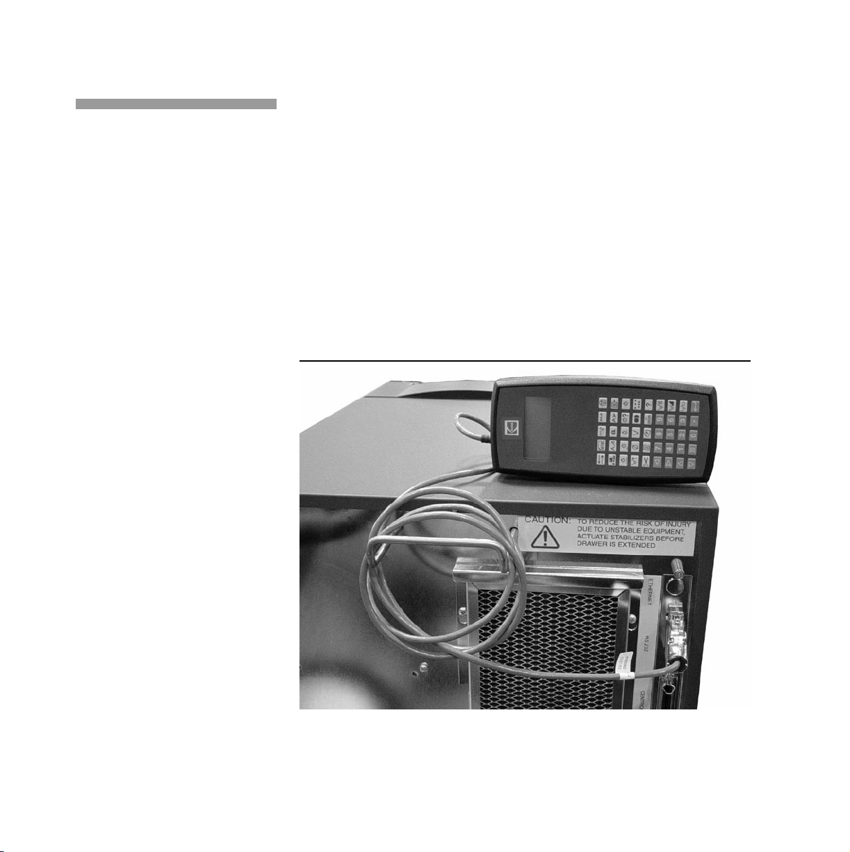
The RCP is connected to the RS232 port on the back of the printer (see
Figure 1) and is powered by that port. The printer provides power only
when it is powered on. The RCP can remain attached during power-up
and shutdown cycles, and can be connected or disconnected when the
printer is powered on (hot plugged).
To install the cable to the remote control panel, carefully push the female
plug snugly into position. Be very careful not to bend the pins. To connect
the remote control panel to the printer, connect the serial port connector
to the RS-232 port at the back of the printer.
Note: Once the cable is connected to the remote control, leave it connected.
When connecting and disconnecting, do so from the printer end only.
Figure 1 Remote control panel attached to DP5120 printer
2 DP5000 Series Remote Control Panel
Page 11
Display
Remote Control Panel Procedures
Display
The Remote Control Panel is a hand held device that allows the operator
to configure the printing behavior of the printer and enable basic printer
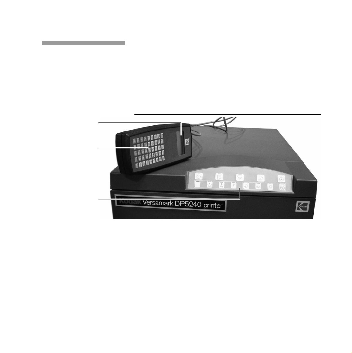
servicing. The RCP has the following functional components (see Figure
2):
• LCD display
•Keypad.
Figure 2 Remote Control Panel functional components
LCD display
Keypad
Printer operator panel
The panel case protects its internal circuitry. To properly maintain the
remote control, apply the following guidelines to its care and use:
• Do not drop the remote control panel or immerse it in water.
• Clean the remote control panel with a damp cloth, do not use solvents
or cleaners. Wipe the remote control panel with a dry cloth after it has
been exposed to moisture.
• Do not take the remote control panel apart. There are no user
serviceable parts inside.
Operator’s Guide 3
Page 12
Remote Control Panel Procedures
Display
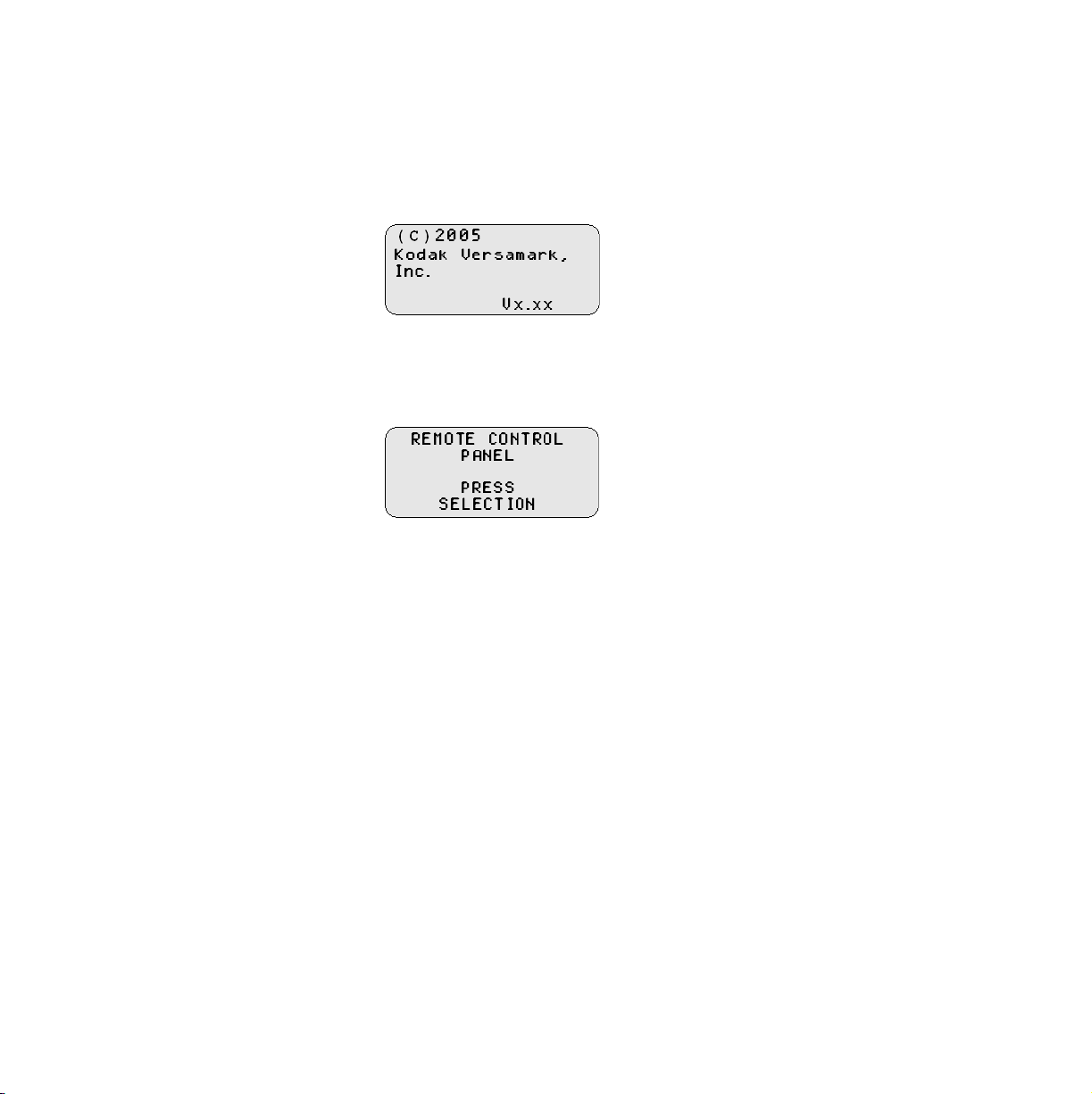
When the RCP is connected, the copyright screen (shown below)
appears and remain displayed connection is established with the printer.
If copyright screen does not clear in 2-3 minutes, check that the cable is
securely connected to the printer port.
The initial selection screen appears 5 seconds after the remote control
panel establishes printer connection. Press any key to skip the 5 second
delay.
4 DP5000 Series Remote Control Panel
Page 13
Selection Screen
Important: When the selection screen is displayed, press the up or down arrow keys
Remote Control Panel Procedures
Selection Screen
A selection screen displays the current printer setting in reverse video.
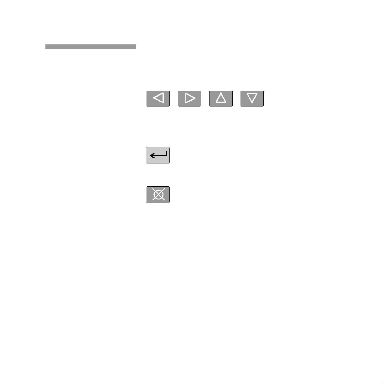
The user uses the arrow keys (shown below) to move between available
selections.
to change the contrast setting of the LCD display.
To activate the selection chosen press the enter key (shown below).
To keep the existing setting press the escape key (shown below).
Note: In Ready, some printer settings cannot be changed and the arrow keys
are disabled. Put the printer in Standby to enable the arrow keys, then
change the settings.
Operator’s Guide 5
Page 14

Remote Control Panel Procedures
Numeric Input Screen
Numeric Input Screen
In a numeric input screen the current printer setting is displayed above
the reverse video input field. The maximum allowable value is displayed
in the lower right hand corner of the screen. The minimum allowable value
is displayed above the maximum allowable value.
• Use the left and right arrows to move within the input field.
• Use the down arrow key to delete the current character.
• Use the numeric keys to enter a new value.
• Press
• Press
ENTER (↵) to send the value setting to the printer.
ESCAPE (!) to return to the previous screen without updating
the value setting to the printer.
Note: If an invalid setting is sent to the printer, the selection will flash and the
previous screen will not appear.
6 DP5000 Series Remote Control Panel
Page 15

Operation
Remote Control Panel Procedures
Operation
The figure below shows the numbers used in the section headings of this
guide to identify the function keys on the remote control panel. Use the
numbers to look up the description of a function or key icon.
Operator’s Guide 7
Page 16

Remote Control Panel Procedures
Keypad
Keypad
1) TRANSPORT DIRECTION
Transport Direction specifies the direction the substrate is moving under
the printhead. See the DP5000 Series
transport direction. This parameter has the following options:
N = Normal
The substrate moves under the printhead starting from the print array
edge of the printhead.
R = Reverse
The substrate moves under the printhead starting from opposite the
print array edge of the printhead.
Operator’s Guide
for details on
Use the arrow keys to position the cursor and then press
selection.
Note: This parameter cannot be changed while the printer is in the Ready State.
8 DP5000 Series Remote Control Panel
↵ to make the
Page 17

Remote Control Panel Procedures
Keypad
2) SUBSTRATE LENGTH
Substrate Length enters a value for the length of the print area. If 0 (zero)
is selected, the print area length is determined by the cue sensor input.
The range for this parameter varies depending on the printer resolution as
follows:
• 120 dpi resolution = 0.0 to 136.0 inches (0.0 to 345.44 cm).
• 240 dpi resolution = 0.0 to 68.0 inches (0.0 to 172.72 cm).
• 480 dpi resolution = 0.0 to 34.0 inches (0.0 to 86.36 cm).
Use the arrow keys to position the cursor, then use the numeral keys to
enter a value and press
Note: This parameter cannot be changed while the printer is in the Ready State.
↵ to confirm the entry.
Operator’s Guide 9
Page 18

Remote Control Panel Procedures
Keypad
3) TACH RATE
Tach Rate specifies the rate of the tachometer installed on the document
transport. This value is measured in pulses per inch (ppi) and the
following options are available:
120
Selects 120 pulses per inch (ppi)
240
Selects 240 ppi
480
Selects 480 ppi
960
Selects 960 ppi
Use the arrow keys to position the cursor and then press
selection.
Printer Resolution (dpi) Supported Tach Rate (ppi)
5120/5122
5240
Note: This parameter cannot be changed while the printer is in the Ready State.
10 DP5000 Series Remote Control Panel
↵ to make the
120x120 120, 240, 480
120x240 120, 240, 480, 960
240x240 120, 240, 480, 960
240x480 240, 480, 960
Page 19

Remote Control Panel Procedures
Keypad
4) TACH SOURCE
Tach Source specifies the source of the tachometer signal. The following
options are displayed:
N = Normal
Tach is entered at the tach/cue connector on the printer connector
panel.
K = K4K
If the K4K interface option is installed, the tach may be entered at the
K4K connector on the printer connector panel.
I = Internal
Used for testing purposes only, this option generates an internal tach
signal.
Use the arrow keys to position the cursor. Press
Note: This parameter cannot be changed while the printer is in the Ready State.
Operator’s Guide 11
↵ to make the selection.
Page 20

Remote Control Panel Procedures
Keypad
5) BASE STOP MODE
Base Stop Mode selects the type of base stop signal to be used. This
signal can be used by the printer to stop the document transport. The
following options are available:
M = Momentary
The signal is activated for 3 seconds when the printer goes offline.
C = Continuous
The signal is activated when the printer goes offline and is
deactivated when the printer goes online. This option allows the
controller to test the printer for online/offline status at any time and
prevents the document transport from being started when the printer
is offline.
Use the arrow keys to position the cursor, then press
selection.
Note: This parameter cannot be changed while the printer is in the Ready State.
12 DP5000 Series Remote Control Panel
↵ to make the
Page 21

Remote Control Panel Procedures
6) CHARACTER SET LANGUAGE
Character Set Language selects from the following list of options:
1 = USA ASCII 13 = SPANISH-1
2 =IRV-2 14 =SPANISH-2
3 = UNITED KINGDOM 15 =SPANISH-3
4 = SWEDEN ISO-11 16 =SPANISH-4
5 = FINLAND/SWEDEN 17 = LATIN AMERICAN
6 =CANADA 18 =GERMAN
7 = JAPAN 19 = FRENCH-1
8 =ITALIAN-1 20 = FRENCH-2
9 =ITALIAN-1 21 = CHINA
10 = ITALIAN-1 22 = DANISH
11 = PORTUGUESE-1 23 = DANISH/NORWAY
12 = PORTUGUESE-2 24 =NORWAY
25 = HUNGARY
26 = SERBIA/CROATIA/SLOVENIA
Keypad
Use the numeral keys to enter the number for a character set from the list
and then press
Use the numeral keys to select a display language value. Press
make the selection.
Note: This parameter cannot be changed while the printer is in the Ready State.
Operator’s Guide 13
↵ to confirm the selection.
↵ to
Page 22

Remote Control Panel Procedures
Keypad
7) CHARACTER SET MODE
Character Set Mode selects the character set language from a list of
extended character sets (character positions 128-255). The following
options are available:
1 = USA ASCII-7
2 = IBM PC-8
3 = Danish/Norwegian-8
4 = Roman-8
5 =ECMA-94
6 =ISO
Use the numeral keys to select a value and press
selection.
Note: This parameter cannot be changed while the printer is in the Ready State.
↵ to make the
14 DP5000 Series Remote Control Panel
Page 23

Remote Control Panel Procedures
Keypad
8) DEFAULT FONT
Use the up and down arrows to scroll the list. Press ↵ to make the
selection.
Select the default font for the printer from the list of available fonts. The
default font is selected by ID number. The font list is sorted by number in
ascending order.
While the font list is being read from the printer, the busy indicator, a small
bar (
⎯) will rotate in the lower left corner of the display.
The plus sign (+) appears by the top entry or bottom entry when more
entries are available above or below those shown on the display.
Note: This parameter cannot be changed while the printer is in the Ready State.
Operator’s Guide 15
Page 24

Remote Control Panel Procedures
Keypad
9) TEXT ORIENTATION and K4K INPUT FORMAT
Use the arrows to select a parameter, then press ↵ to display that screen.
Text Orientation
Use the arrows to select and then press ↵ confirm one of these options:
0°
The printed image is readable as printed when the substrate is
moving left to right.
90°
The image is printed perpendicular to substrate movement with
the left edge of the text against the top of the piece.
180°
270°
K4K Input Format
Use the arrows then
N = Native Input Command (NIC) input
A = Admark format.
16 DP5000 Series Remote Control Panel
The image is printed upside-down when the substrate is moving
left to right.
The image is printed perpendicular to substrate movement with
the left edge of the text against the bottom of the piece.
↵ to select and confirm one of these options:
Page 25

Remote Control Panel Procedures
Keypad
10) DEFAULT LINE SPACING
Use the up and down arrows keys to scroll the list. Press ↵ to make the
selection.
The plus sign (+) appears by the top entry or bottom entry when more
entries are available above or below those shown on the display.
F = FONT SET
F appears at the top of the scroll when the line spacing is taken from
the active font.
U = USER DEFINED
U appears at the bottom of the scroll.
When U is selected, the following input screen appears.
Use the arrow keys to position the cursor. Use the numeral keys to enter a
value. Press
values and to return to the selection screen above.
If English is the selected unit of measure, the following options are
available:
Font Set, 2 lpi, 3 lpi, 4 lpi, 5 lpi, 6 lpi, 7 lpi, 8 lpi, 9 lpi, 10 lpi, 11 lpi, 12
lpi, and User-Defined.
If Metric is the selected unit of measure, the following options are
available:
Font Set, 0.8 l/cm, 1.2 l/cm, 1.6 l/cm, 2.0 l/cm, 2.4 l/cm, 2.8 l/cm, 3.2 l/
cm, 3.6 l/cm, 4.0 l/cm, 4.4 l/cm, 4.8 l/cm, and User-Defined.
Note: This parameter cannot be changed while the printer is in the Ready State.
Operator’s Guide 17
↵ to send the value to the printer. Press ! to enter no
Page 26

Remote Control Panel Procedures
Keypad
11) CUE DELAY
Cue Delay is the distance from the leading edge of the substrate to the
start of the image target area. This value determines image position,
which is the first line of the printed image as it appears on the substrate.
Cue Delay has the same maximum length limits that Substrate Length
has (based on resolution setting).
Use the arrow keys to position the cursor. Use the numeral keys to enter a
value and then press
Note: This parameter cannot be changed while the printer is in the Ready State.
↵ to confirm the entry.
18 DP5000 Series Remote Control Panel
Page 27

Remote Control Panel Procedures
Keypad
12) CUE DISTANCE
Cue Distance is measured from the cue sensor to the print array. The
minimum cue distance 1.0 in. (2.54 cm). (See the DP5000 Series
Operator’s Guide
Cue Distance has the same maximum dimension limits that Substrate
Length has (based on resolution setting).
Use the arrow keys to position the cursor, then use the numeral keys to
enter a value and press
Note: This parameter cannot be changed while the printer is in the Ready State.
for details on cue distance.)
↵ to confirm the entry.
Operator’s Guide 19
Page 28

Remote Control Panel Procedures
Keypad
13) CUE SOURCE
Use the arrow keys to select on of the following options, then press ↵ to
confirm the selection.
N = Normal
Cue is entered at the tach/cue connector on the printer connector
panel.
K = K4K
If the K4K interface option is installed, cue may be entered at the K4K
connector on the printer connector panel.
I = Internal
Used for testing purposes only, this option generates an internal cue
signal.
O = I/O
Cue is entered at the I/O connector on the printer connector panel.
NI = Normal Inverted
Inverts the current cue signal coming from the tach/cue connector.
KI = K4K Inverted
Inverts the cue signal co5ming from the K4K connector.
II = Internal Inverted
Inverts the cue signal being generated internally.
OI = I/O Inverted
Inverts the cue signal coming from the I/O connector.
Note: This parameter cannot be changed while the printer is in the Ready State.
20 DP5000 Series Remote Control Panel
Page 29

Remote Control Panel Procedures
Keypad
14) CUE ERROR
Use the arrow keys to select one of the following options, then press ↵ to
confirm the selection.
I = Ignore
Continue printing when a cue or piece overrun error is detected.
C = Cue
Stop printing when a cue overrun error is detected and report error
MC-05. This error occurs when the substrate feed rate is too high,
data is missing, or too much data exists for each image.
P = Piece
Stop printing when a piece overrun error is detected and report error
MC-08. This error results from an image length that exceeds the print
area. See Parameter 2. “Substrate Length”.
C/P = Cue/Piece
Stop printing when a cue or piece overrun error is detected. Either an
MC-05 or MC-08 error message is generated.
Note: This parameter cannot be changed while the printer is in the Ready State.
Operator’s Guide 21
Page 30

Remote Control Panel Procedures
Keypad
15) CUE MODE
Cue mode specifies the printer’s internal response to the cue signal.
Use the arrow keys to select one of the following options, then press
confirm the selection:
N = Normal
The printer handles cue distance, cue delay, and time of flight
compensation information when the cue signal is received.
P = Pass Through
Printing is enabled immediately after the cue signal is received, with
no delay for internal processing.
W = Web
Printing begins when the cue signal is received and continues as long
as data is available to print.
Note: This parameter cannot be changed while the printer is in the Ready State.
↵ to
22 DP5000 Series Remote Control Panel
Page 31

Remote Control Panel Procedures
Keypad
16) PRINTHEAD HEIGHT
Printhead Height specifies the distance between the print array (bottom of
the printhead) and the substrate.
Use the arrow keys to select one of the displayed values, then press
confirm the selection.
Apply the following guidelines to setting this parameter:\
• Printhead height affects print quality. To ensure the highest print
quality, the lowest possible print height should always be used.
• Optimum print quality for both the 5120, 5240, and 5122 printers is
obtained at a printhead height of 0.125 inch. (3.2 mm). At this height,
high resolution print is at Near Letter Quality (NLQ).
• When using a printhead height that exceeds 0.125 in. (3.2 mm),
select Odd Skip/Even Skip as the Print Density.
• Using Odd Skip/Even Skip print density reduces the maximum print
job speed. Test samples should always be printed to verify that print
quality is appropriate for the current job.
Note: This parameter cannot be changed while the printer is in the Ready State.
↵ to
Operator’s Guide 23
Page 32

Remote Control Panel Procedures
Keypad
17) PRINTHEAD PHASE
Use the arrow keys to position the cursor, then press ↵ to confirm the
selection.
Enter the value for the printhead charging phase, which appears on the
printhead label. This value is factory-set for the 5240 and 5122 printheads
(but not the 5120 printhead). Phase can be adjusted if problems with print
quality arise. The range is 1 to 55 counts. Check print quality after
adjusting this value. (See the DP5000 Series
on verifying print quality.)
Note: This parameter cannot be changed while the printer is in the Ready State.
Operator’s Guide
for details
24 DP5000 Series Remote Control Panel
Page 33

Remote Control Panel Procedures
Keypad
18) PRINTHEAD VOLTS
Use the arrow keys to position the cursor, then press ↵ to confirm the
selection.
Enter the value for the charge lead voltage being applied to the printhead,
which appears on the printhead label. This value is factory-set for the
5240 and 5122 printheads (but not the 5120 printhead), and that setting is
on printhead label. Voltage can be adjusted if problems with print quality
arise. The range is 100 to 180 volts. Check print quality after adjusting this
value. (See the DP5000 Series
print quality.)
Operator’s Guide
for details on verifying
Operator’s Guide 25
Page 34

Remote Control Panel Procedures
Keypad
19) PRINT DENSITY
Print Density is the number of drops of ink used to produce a dot of ink on
the substrate. Print quality can be improved by changing print density,
making the image lighter or darker; however, changing print density can
also affect print resolution, making the resolution of smaller fonts more
difficult to read.
Use the arrow keys to select one of the following options, then press
confirm the selection:
1 = 1 Drop per Dot
One drop of ink is released to print one dot of ink on the substrate.
2= 2 Drops per Dot
Two drops of ink are released to print one dot of ink on the substrate.
O/E = Odd/Even
One drop of ink is released to print a dot of ink on the substrate;
however, every other drop of ink is skipped. This option can improve
print quality by eliminating a condition known as crosstalk. Crosstalk
occurs when the charge applied to one drop of ink disturbs the flight
of an adjacent drop, causing that drop to be deflected. This parameter
is not valid for the 5240 printer.
OS/ES = Odd-Skip/Even-Skip
Printing occurs every second cycle, alternating with a non-printing
cycle. This option should be used when printing at printhead heights
exceeding the recommended height of 0.125 in. (0.32 cm). Print
quality is improved by reducing crosstalk.
Note: This parameter cannot be changed while the printer is in the Ready State.
↵ to
26 DP5000 Series Remote Control Panel
Page 35

Remote Control Panel Procedures
Keypad
20) RESOLUTION
Select the print resolution, which is the degree of sharpness of an image,
measured in dots per inch (dpi). Vertical print resolution is perpendicular
to document movement, while horizontal resolution is parallel to
document movement. Control Panel only displays the parameter options
available for the printer you are operating.
When the print resolution is changed, the printer reloads its embedded
fonts. This operation may take several minutes.
When printing at high resolution, use a high resolution font and set the
printhead height at 0.12 in. (0.30 cm) or less from the substrate.
Use the arrow keys to select one of the following displayed options, then
↵ to confirm the selection:
press
120x120
Standard resolution for the 5120 and 5122
120x240
High resolution for the 5120 and 5122
240x240
Standard resolution for the 5240
240x480
High resolution for the 5240.
Note: This parameter cannot be changed while the printer is in the Ready State.
Operator’s Guide 27
Page 36

Remote Control Panel Procedures
Keypad
21) PIECE TERMINATION and SORT CONTROLS
Use the arrows to select a parameter, then press ↵ to display that screen.
Piece Termination
Piece Termination specifies the method used by the printer to identify
when the last piece of data for a piece is received.
Use the arrow keys to select one of the following options, then press
confirm the selection:
M = Margin
The end of the piece is reached when the bottom margin is exceeded
or the printer receives a form feed character.
F = Form Feed
The end of the piece is reached when the printer receives a form feed
character.
28 DP5000 Series Remote Control Panel
↵ to
Page 37

Remote Control Panel Procedures
Keypad
Sort Controls
Sort controls define how sort commands are processed when present.
Use the arrow keys to select any of the following four parameters
displayed, then press
SORT MODE
ACTIVATION EDGE
SORT PULSE WIDTH
SORT A-E
Sort Mode
↵ to display the screen for that parameter:
Use the arrow keys to select one of the following options, then press
↵ to confirm the selection:
S = Select
Use when only one sort gate is activated per document.
B = Binary
Use when two or more sort gates are activated per document.
The combination is based upon the binary value of the character
in the sort commands. When binary is used, the sort command in
the input data determines the sort gate to be activated; however,
each sort gate uses the delay and duration values assigned to
sort code A.
Operator’s Guide 29
Page 38

Remote Control Panel Procedures
Keypad
Sort Activation Edge
Sort Activation Edge specifies the edge of the piece at which the sort
gate activation or deactivation occurs. Use the arrow keys to select
one of the following options, then press
L = Leading
Activation and deactivation of the sort gate occurs at the start of
the first row of the printed image.
T = Trailing
Activation and deactivation of the sort gate occurs at the end of
the last row of the printed image.
Sort Pulse Width
↵ to confirm the selection:
Sort Pulse Width determines the length of time in seconds that the
sort gate remains active. The range is 0.00 to 9.99 sec. The sort gate
is activated in 0.01 sec. increments. If a pulse width of 0.00 is
selected, the sort pulse is activated for a cue period. A cue period is
the time elapsing between signals. Use the arrow keys to position the
cursor, then use the numeral keys to enter a value and press
confirm the entry.
Note: Because 0.01 seconds is too short to activate the relay, the minimum
delay should be 0.02 seconds.
30 DP5000 Series Remote Control Panel
↵ to
Page 39

Remote Control Panel Procedures
Keypad
Sort A-E
Sort A-E specifies the handling of five sort gate outputs for the printer.
Use the arrow keys to select on the displayed sort codes, then press
↵ to display the screen for that code.
On the Sort Code display, use the arrow keys to select each of the
following parameters, then press
parameter:
DELAY
DURATION
↵ to display the screen for that
Sort Code Delay is the number of pieces printed between detection of
a sort code and activation of the specified sort gate. When a value of
0 is entered, the sort gate is activated at the document containing the
code. When the sort mode is Binary, only values for sort code A are
applicable. The range is 0 to 99 pieces. Use the arrow keys to
position the cursor and then use the numeral keys to enter a value.
Press
↵ to confirm the entry.
Operator’s Guide 31
Page 40

Remote Control Panel Procedures
Keypad
Sort Code Duration is the number of pieces printed before the sort
gate is deactivated. When the sort mode is Binary, only values for sort
code A are applicable. The range is 0-99 pieces. When 0 is selected,
the sort gate is not activated.
If a sort gate is already activated and that sort gate is detected again,
the sort gate remains active for the specified duration for the second
time. The delay and duration values have the same meaning for the
other gates.
Use the arrow keys to position the cursor and then use the numeral
keys to enter a value. Press
↵ to confirm the value.
32 DP5000 Series Remote Control Panel
Page 41

Remote Control Panel Procedures
Keypad
22) PRINTING COMPLETE
Printing Complete specifies when you wish the host controller to be
notified that a piece has been printed by specifying the edge of the
document at which the printing completed signal is activated. Use the
cursor to select one of the following options, then press
selection:
T 10µs
Selects TRAILING edge and 10 microseconds
L 10µs
Selects LEADING and 10 microseconds
T 20ms
Selects TRAILING and 20 milliseconds
L 20ms
Selects LEADING and 20 milliseconds
↵ to confirm the
The following guidelines apply to these parameters:
Trailing
The signal is activated when at the end of the last row of the
printed image.
Leading
The signal is activated at the start of the first row of the printed
image.
Note: This parameter cannot be changed while the printer is in the Ready State.
Operator’s Guide 33
Page 42

Remote Control Panel Procedures
Keypad
23) DUPLICATION COUNT
Duplication Count specifies the number of times (1 to 999999) the printer
is to print the document. For example, if 5 is entered, 5 copies of the
document are printed.
Use the arrow keys to position the cursor, then use the numeral keys to
enter a value and press
Note: This parameter cannot be changed while the printer is in the Ready State.
↵ to confirm the entry.
34 DP5000 Series Remote Control Panel
Page 43

Remote Control Panel Procedures
Keypad
24) UNITS
Units selects the units of measure for position and length values. Use the
cursor to select one of the following options, then press
selection:
I
INCH selects English units of measure
M
METRIC selects standard International units of measure.
↵ to confirm the
Operator’s Guide 35
Page 44
Remote Control Panel Procedures
Keypad
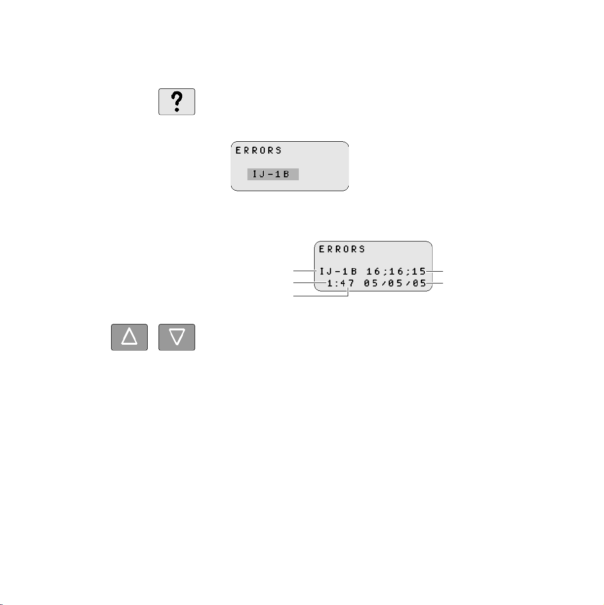
25) ERRORS
When the errors key (?) is pressed, one of the following displays appears:
•ERRORS
Any pending error is displayed (example shown below).
• ERROR LOG
If no error is pending, the error log is displayed (as shown below).
Error code
Entry displayed
Total entries read
Time of displayed entry
Date of displayed entry
Use the up and down arrow keys to scroll through the log (if it contains
multiple entries). The last entry logged by the printer is entry 1. To view
previously logged errors, press the down error.
Press
↵ to clear display and return to previous display.
36 DP5000 Series Remote Control Panel
Page 45

Remote Control Panel Procedures
Keypad
26) PRINTHEAD STATE TABLE
Printhead state table select a fluid system state for the printer. Use the
cursor to select one of the following options, then press
selection:
C = Circulate
Defines the states used to bring up the printhead for diagnostic
operation.
N = Normal
Defines the states used to bring the printhead up or down during
normal operation.
P = Purge
Defines the states used during a fluid system purge.
Transitions between states take varying amounts of time.
↵ to confirm the
Note: This parameter can only be changed while the printer is in the Down
State.
Operator’s Guide 37
Page 46

Remote Control Panel Procedures
Keypad
27) PRINTHEAD STATE NUMBER
Current state
Previous state
Current table
Printhead State Number specifies the state within the active table
selected by the Printhead State Table key. The current state is displayed
over the previous state. A rotating bar (
⎯) displayed in place of the
previous state indicates the printer is in transition to prior requested state.
Use the arrow keys on this display to select a fluid system state. Position
the cursor of the state number and use the numeral keys to enter a value,
then press enter (
↵) to put the printer in that state.
The current state is identified by the following codes on this display:
N
Selects the Normal Up table
C
Selects the Circulate table
P
Selects the Purge table.
Transitions between states take varying amounts of time.
38 DP5000 Series Remote Control Panel
Page 47

Remote Control Panel Procedures
28) PRINTHEAD COMMAND
Printhead commands generate the printer operations listed below:
S
Selects Standby to turn the fluid system on with the eyelid closed.
This state allows you to leave the fluid system on but protects the
orifice plate from contamination. Use this action when leaving the
printer idle for more than 1 hour (but less than 7 hours) or when
troubleshooting.
R
Selects Ready to turn the fluid system on with the eyelid open. The
printer must be placed in the ready before attempting to print.
D
Selects Down to turn the fluid system off and close the eyelid.
C
Initiates a printhead clean.
Keypad
Use the arrow keys to position the cursor over a code, then press
enter that command.
Operator’s Guide 39
↵ to
Page 48

Remote Control Panel Procedures
IJPDS Ethernet Kit
IJPDS Ethernet Kit
If the remote control panel is to be used with a 5000 series printer with the
IJPDS Ethernet Kit option, only the following functions will be accessible
on the Remote Control Panel.
• Tach rate
• Tach source
• Cue source
•Cue mode
• Printhead phase
• Printhead volts
• Resolution
• Errors
• Printhead state table
• Printhead state number
• Printhead commands
If the remote control panel is used with a 5000 series printer operating
with IJPDS Ethernet, the following screen will be displayed when a
function is selected that is not available.
Press
40 DP5000 Series Remote Control Panel
↵ or ! to return to previous display.
Page 49

Page 50

0113455-602
0113455-603
© Kodak Versamark, Inc.
 Loading...