

Page 1
DCS
700
Series Digital Cameras
User’s Guide
for the DCS 700 Series Digital Cameras
Page 2

Page 3

© Eastman Kodak Company and Nikon Corp., 2001 All rights reserved
Kodak and Kodak Professional are trademarks of Eastman Kodak Compan y
Adobe, Photoshop, and Acrobat are trademarks of Adobe Systems Inc.
Page 4

CAREFULLY READ THE FOLLOWING WARRANTY TERMS AND CONDITIONS
BEFORE USING YOUR CAMERA. USE OF YOUR CAMERA INDICATES YOUR
ACCEPTANCE OF THESE TERMS AND CONDITIONS. IF YOU DO NOT AGREE
WITH THEM, PROMPTLY RETURN THE CAMERA, UNUSED, ALONG WITH THE
ACCOMPANYING MATERIALS, IN THE ORIGINAL PACKAGING.
WARRANTY
KODAK PROFESSIONAL DCS 700 Series Digital Camera
THIS WARRANTY APPLIES ONLY TO EQUIPMENT PURCHASED IN THE
UNITED STATES.
Kodak warrants your KODAK PROFESSIONAL DCS 700 Series Digital Camera to be
free from defects in material and workmanship for 1 year or 100,000 shutter activations
from the day of purchase, whichever occurs first.
Warranty Repair Coverage
If this equipment does not function properly during the warranty period due to defects in
material or workmanship, Kodak will, at its option, either repair or replace the equipment
without charge, subject to the conditions and limitations stated herein. Such repair service
will include all labor as well as any necessary adjustments and/or replacement parts.
If replacement parts are used in making repairs, these parts may be remanufactured, or
may contain remanufactured materials. If it is necessary to replace the entire system,
Kodak may replace it with a remanufactured system. Repair or replacement carries a
30-day warranty effective at the time of service problem resolution. This warranty will not
extend the original warranty period, and in the case of parts replacement, will only apply
to parts and labor performed to repair the equipment.
Page 5

Limitations
REPAIR OR REPLACEMENT WITHOUT CHARGE IS KODAK’S ONLY OBLIGATION
UNDER THIS WARRANTY.
Warranty service will not be provided without dated proof of purchase. Please return
the Warranty Registration card within 30 days of pu rchase.
As a condition of warranty service, before sending in your equipment to a Kodak
authorized service center for repair, you must first contact a Kodak representative for
return authorization and instructions.
Should you need to return equipment to Kodak, Kodak is not responsible for the loss or
damage of equipment while in transport to a Kodak authorized service center. You may, at
your option, choose to insure equipment for loss or damage with the carrier of your
choice.
This warranty becomes null and void if, during shipment, you fail to pack your KODAK
PROFESSIONAL DCS 700 Series Digital Camera in a manner consistent with the
repacking instructions.
This warranty does not cover the following:
✔ Circumstances beyond Kodak’s control
✔ Service or parts to correct problems resulting from the use of attachments,
accessories or alterations not marketed by Kodak
✔ Unauthorized modifications or service
✔ Misuse
✔ Abuse
✔ Failure to follow Kodak’s operating, maintenance, or repacking instructions
✔ Failure to use Kodak supplied items (such as cables).
KODAK MAKES NO OTHER WARRANTIES, EXPRESS OR IMPLIED, AND
SPECIFICALLY DISCLAIMS THE IMPLIED WARRANTIES OF MERCHANTABILITY
AND FITNESS FOR A PARTICULAR PURPOSE.
KODAK WILL NOT BE RESPONSIBLE FOR ANY CONSEQUENTIAL OR INCIDENTAL
DAMAGES RESULTING FROM THE PURCHASE, USE, OR IMPROPER FUNCTIONING
OF THIS EQUIPMENT EVEN IF THE LOSS OR DAMAGE IS CAUSED BY THE
NEGLIGENCE OR OTHER FAUL T OF KODAK. SUCH DAMAGES FOR WHICH KODAK
WILL NOT BE RESPONSIBLE INCLUDE, BUT ARE NOT LIMITED TO, LOSS OF
REVENUE OR PROFIT, DOWNTIME COSTS, LOSS OF USE OF YOUR CAMERA,
COST OF ANY SUBSTITUTE EQUIPMENT, FACILITIES, OR SERVICES, OR CLAIMS
OF YOUR CUSTOMERS FOR SUCH DAMAGES.
Page 6

Outside the United States
In countries other than the United States, warranty terms may be different. Unless a
specific Kodak warranty is communicated to the purchaser in writing by Kodak, no
warranty or liability exists even though defect, damage or loss may be by negligence or
other act of Kodak.
How to obtain service
In the United States, call 1-800-23-KODAK (1-800-235-6325).
In Canada, call 1-800-GO-KODAK (1-800-465-6325).
In other countries, call your nearest Kodak representative.
If service is required, your Kodak representative will instruct you to return the unit to the
nearest service center for repair and will issue a return authorization number.
When returning a KODAK PROFESSIONAL DCS 700 Series Digital Camera for repair,
you should pack the unit in its original packing materials according to the repacking
instructions located on the shipping container. The problem report form, located at the
back of this manual, should also be completed and enclosed with your camera. Packing
will be the purchaser’s responsibility if the original packaging has been discarded or is not
available.
Return of the repaired or replaced equipment to the customer can be expected five to
seven business days from the date the equipment is received by the service center.
Page 7

Product Support Options
During the warranty period for the KODAK PROFESSIONAL DCS 700 Series Digital
Camera, you are entitled to product support for both hardware and software, provided
your camera is registered with Eastman Kodak Company. You may register with Kodak
via mail, fax, or through Kodak’s World Wide Web site: http://www.kodak.com.
Support is provided through a variety of options:
1 Technical Support through the web site (http://www.kodak.com):
Support includes FAQs (Frequently Asked Questions), downloadable software
updates, and technical topic articles for reading and downloading.
2 FaxBack Documents on a variety of subjects. In North America, the FaxBack system
is available at the following phone number: 1-800-508-1531
3 Authorized Dealers:
Contact your authorized KODAK PROFESSIONAL dealer for help with camera
operation and connection to your computer. Many dealers can also provide training for
your graphics application softw are, integ rat i on cons ult ing, and optional equipment.
Authorized dealers can also provide help in purchasing a service maintenance
agreement.
4 T e l eph one Support:
Telephone support is available without charge during your warranty period only, by
calling:
United States: Call 1-800-23-KODAK (1-800-235-6325)
Outside United States: Contact your local Kodak service representative
Your camera must be registered with Kodak to qualify for no-charge support. You will
be asked to provide the serial number of your camera, and proof of purchase also may
be requested to verify the current status of your warranty. Cameras found to be out of
warranty will require a credit card payment for each call incident. There is no charge to
register your camera with Kodak.
Page 8

5 Out-of-Warranty Support Options
There will be a charge for out-of-warranty call incidents if you wish to speak to a
Kodak support representative. A call incident is defined to include only those issues
raised during the first telephone or email contact. Follow-up telephone calls by
Kodak’s representative, and callbacks to Kodak’s Support Center to resolve the call
incident will not be charged, provided a valid, active call number is provided. Calls to
report bugs or anomalies will have any charges cancelled. Calls to arrange for service
will have the charges cancelled or applied as a credit against the repair estimate or
invoice.
Service maintenance agreements, which cover the repair and support of the DCS 700
Series Camera and software, are available. In North America, please contact the
regional Service Marketing group at: 1-800-645-6325
No-charge options include:
• KODAK PROFESSIONAL World W ide W eb site:
http://www.kodak.com/go/support
• FaxBack documents
• Your KODAK PROFESSIONAL dealer
Page 9

Page 10

Table of Contents
Important Information ..................................................1-1
System Requirements for your Computer................................................ 1-2
Macintosh ........................................................................................ 1-2
Windows ..........................................................................................1-2
Electromagnetic Emissions.................................... .................................. 1-7
VCCI Statement..................................................... ..... ............................. 1-7
About Your Camera .....................................................2-1
Nomenclature........................................................................................... 2-3
Camera Front .................................... ...... ........................................ .2-3
Camera Back ................................................ ..... ...... ........................2-4
Camera Top .....................................................................................2-5
Camera Bottom ................................................................... .............2-5
Contents
Camera Sides ............................... ..... ...... ........................................ .2-6
Open Battery/PC Card Door ............................................................2-7
Viewfinder ............................................................................................... 2-8
LCD Panels.............................................................................................. 2-9
Top Status LCD ...............................................................................2-9
Back Status LCD ...........................................................................2-10
Image LCD .................................................................................... 2-11
Digital Buttons....................................................................................... 2-14
Four-way Switch ...........................................................................2-14
Menu Button ..................................................................................2-14
Page 11

OK Button .....................................................................................2-14
Cancel Button ................................................................................2-14
Tag/Record Button ........................................................................2 -14
Quick Guide for Using the Image LCD and Digital Buttons................ 2-15
Command Dials ..................................................................................... 2-16
Main-Command Dial ..................... ........................................ ...... .2-16
Sub-Command Dial .......................................................................2-18
Drive Mode/Self-timer Selector............................................................. 2-19
Lens............................................... ...... ..... ........................................ ...... 2-20
Mounting the Lens .............. ........................................ ..... .............2-20
Setting the Lens to the Minimum Aperture ...................................2-21
Removing the Lens .......................................................................2-22
Imager.......................... ...... ...... ....................................... ...... ................. 2-23
IR Filter.................................................................................................. 2-23
Viewfinder Diopter................................................................................ 2-24
Illumination Switch................................................................................ 2-25
Mirror Lockup Lever............................................................................. 2-26
Depth-of-Field Preview Button ............................................................. 2-27
Accessory Shoe ...................................................................................... 2-28
Sync Terminal.......................... ..... ........................................ ..... ...... ...... 2-28
Self-Diagnostic Shutter System............................................................. 2-29
Changing Viewfinders........................................................................... 2-30
Removing the Finder .....................................................................2-30
Attaching the Finder ............................................................... ...... .2-31
Changing Focusing Screens................................................................... 2-32
Page 12

Camera Straps........................... ...... ...... ....................................... .......... 2-33
Attaching the Neck Strap ..............................................................2-33
Attaching the Hand Strap ..............................................................2-34
Software Overview ................................................................................ 2-35
Name Plate............................................................. ................................ 2-35
Powering Your Camera ................................................3-1
Turning the Camera On and Off.............................................................. 3-1
Batteries ................................................................................................... 3-2
Disposing of Batteries .....................................................................3-3
Inserting/Removing Batteries ..........................................................3-4
Checking Battery Status ..................................................................3-7
Battery Charger........................................................................................ 3-8
Charging Batteries ................................. ...... ..... ..............................3-9
Conditioning (Discharging Batteries) ...........................................3-11
Battery Conservation ............................................................................. 3-12
Contents
PowerSave Mode ...........................................................................3-12
Image LCD Panel Timeout ............................................................3-13
Meter Timeout .................................. ...... ...... .................................3-13
Situations Using Extra Battery Power ...........................................3-13
AC Adapter for Camera......................................................................... 3-14
Connecting the AC Adapter for Camera .......................................3-15
Configuring Your Camera ...........................................4-1
Date and Time.......................................................................................... 4-1
Camera Properties.............................................................................. ...... 4-2
Displaying the Properties Menu ......................................................4-2
Battery Save Onset ..........................................................................4-3
Page 13

Display Off Time ............................................................................4-3
Total Actuations ..............................................................................4-4
Use Folder 1 ................................................................................. ...4-4
Video Format ............................ ....................................... ...... .........4-5
Custom Settings....................................................................................... 4-5
Using a PC Card ..........................................................5-1
PC Cards.................................................................................................. 5-1
Dual Slots for PC Cards ..................................................................5-2
Inserting/Removing PC Cards ......................................................... 5-3
Formatting a PC Card ......................................................................5-6
Selecting a PC Card or Folder .........................................................5-8
Controlling Exposure ...................................................6-1
White Balance.......................... ..... ...... ....................................... ...... ........ 6-1
Choosing a White Balance Setting ..................................................6-3
Custom White Balance Setup ..........................................................6-4
Exposure Metering System ...................................................................... 6-9
3D Color Matrix Metering ..............................................................6-9
Center-Weighted Metering .......................................... ..................6-10
Spot Metering ................................................................................6-11
Setting the Metering System .........................................................6-12
Exposure Mode.............................................. ...... ..... ............................. 6-13
Setting Exposure Mode .................................................................6-16
Focusing ............................. ...... ....... ...... ....... ....... ...... ... 7-1
Focus Area............................................................................................... 7-1
Selecting the Focus Area .................................................................7-1
Selecting AF Area Mode .................................................................7-4
Page 14

Focus Mode........................................................................................ ...... 7-6
Autofocus ........................................................................................7-6
Manual Focus ................................................................................7-10
Special Focusing Situations in AF......................................................... 7-13
IR Filter or Anti-aliasing Filter: Effect on Focus................................... 7-15
Sharpening ............................................................................................. 7-16
Capturing Images .........................................................8-1
Preparing to Capture an Image ................................................................ 8-1
Basic Shooting......................................................................................... 8-3
Two-Button Reset ............................................................................8-8
ISO........................................................................................................... 8-9
Drive Mode............................................................................................ 8-10
Choosing a Drive Mode ................................................................8-10
Using the Vertical Controls ................................................................... 8-12
Contents
Intervalometer........................................................................................ 8-13
Job Tracker............................................................................................. 8-15
Loading Job Tracker Data from a PC Card ...................................8-16
Flash Photography .......................................................9-1
Recommendations for Flash Photography................................... ...... ...... 9-1
Auto Aperture Mode................................................................................ 9-2
Attaching the SB-28D or SB-28DX Speedlight...................................... 9-3
Turning on the SB-28D or SB-28DX Speedlight.................................... 9-3
Standby Mode........................... ...... ...... ....................................... ...... ...... 9-4
Enabling/Disabling Standby Mode .................................................9-4
Page 15

Waking the SB-28D or SB-28DX Speedlights from Standby mode. 9-4
Setting Up Your Camera for Flash Photography..................................... 9-5
Setting Up the SB-28D or SB-28DX Speedlight..................................... 9-7
Test Firing................................................................................................ 9-9
Using the SB-28D Speedlight................................................................ 9-10
Auto Flash Distance Range.................................................................... 9-11
Flash Sync Mode ..................... ..... ...... ....................................... ...... ...... 9-13
Slow Sync ......................................................................................9-13
Rear Curtain Sync ......................................................................... 9-15
Guide Numbers for Determining the Correct Aperture......................... 9-17
Calculating the Correct Aperture ..................................................9-17
Calculating the Shooting Distance ................................................ 9-17
Guide Number Table .....................................................................9-17
Working with Images on the Camera ........................10-1
Reviewing Images.................................................................................. 10-1
Selecting a Display Mode ............................................................. 10-2
Single Image Display Mode ..........................................................10-3
Zoom Display Mode .....................................................................10-3
Histogram Display Mode .............................................................. 10-5
Multiple Image Display Mode ......................................................10-5
Delete Display Mode .....................................................................10-6
Navigating Through Images ..........................................................10-7
Selecting an Image ........................................................................ 10-7
Status Bar ...................................................................................... 10-8
Location Bar ..................................................................................10-8
Deleting Groups of Images.................................................................... 10-9
Page 16

Display Contrast................................................................................... 10-10
Overexposure Indicator........................................................................ 10-10
Tagging Images.................................................................................... 10-11
Associating Sound Files With Images................................................. 10-12
Recovering Deleted Images................................................................. 10-14
Advanced Operation ..................................................11-1
Capturing Images in Each Exposure Mode ........................................... 11-1
Shutter-Priority Auto Exposure Mode ..........................................11-1
Aperture-Priority Auto Exposure Mode ........................................11-4
Manual Exposure Mode ................................................................11-8
Flexible Program.................................................... ..... ...... ................... 11-13
Focus Lock For Off-center Subjects.................................................... 11-14
AE/AF Lock......................................................................................... 11-16
About AE Lock ...........................................................................11-17
Exposure Compensation...................................................................... 11-19
Contents
Obtaining the Meter Reading in Manual Exposure Mode ..........11-20
Exposure Compensation Function ...............................................11-22
Auto Exposure/Flash Exposure Bracketing ................................11-24
Self-timer ......................................................... ...... .............................. 11-28
Long Time Exposure............................................................................ 11-30
Custom Settings................................................................................... 11-32
Making a Custom Setting ............................................................11-32
Reset Factory Settings .................................................................11-33
Custom Settings Table ................................................................11-34
Connecting to Your Computer ...................................12-1
Page 17

Advantages to using an IEEE 1394 Connection ...........................12-1
Advantages to using a Card Reader ..............................................12-1
Connecting Your Camera to the Computer ........................................... 12-2
Quitting—Disconnecting from the Computer....................................... 12-4
Using the Card Reader........................................................................... 12-4
Transmitting Data ......................................................13-1
Connecting a Device to the Serial Port.................................................. 13-1
Accessing Serial Port Options ............................................................... 13-2
Setting the Baud Rate ....................................................................13-2
Serial In Mode ...............................................................................13-3
Serial In Status ..............................................................................13-4
Serial Out Mode ............................................................................ 13-5
Camera Care ..............................................................14-1
Handling................................... ..... ........................................ ..... ............ 14-1
Cleaning................................................... ........................................ ...... 14-2
IR Filter or Anti-aliasing Filter.............................................................. 14-3
Removing, Cleaning, and Installing the IR or Anti-aliasing Filter 14-3
The Imager............................................................................ ..... ............ 14-5
Determining if the Imager is Dirty ................................................14-5
Cleaning the Imager ......................................................................14-8
Reassembling the Camera .............................................................14-8
Storing................................................. ..... ...... ........................................ 14-9
Top and Back Status LCDs.................................................................... 14-9
Installing Camera Firmware on Your Computer................................. 14-10
Updating Camera Firmware................................................................. 14-10
Page 18

Updating From the PC Card .......................................... ..............14-11
Appendix A - Specifications .......................................A-1
Appendix B - Troubleshooting ...................................B-1
Other symptoms, causes and remedies................................................... B-3
Appendix C - Lens and Viewfinder Compatibility .....C-1
Compatible Lenses.................................................................................. C-1
Manual Single Focal Length Lenses .............................................. C-1
Manual Zoom Lenses ..................................................................... C-5
Autofocus Single Focal Length Lenses .......................................... C-6
Autofocus Zoom Lenses .......................................... ....................... C-8
Compatible Viewfinders....................................................................... C-10
Appendix D - Glossary ...............................................D-1
Appendix E - Problem Report ..................................... E-1
Appendix F - Remote Control Accessories ................ F-1
Contents
Page 19

Page 20

INSERT
PHOTO
HERE
1
Important Information
Thank you for purchasing your new KODAK PROFESSIONAL DCS 700 Series Digital
Camera (DCS 700 Series camera). This portable camera system, which combines
technologies of Eastman Kodak Company and NIKON Corporation, allows you to take
and store high-resolution, high-quality digital images. Before you start using the camera,
you should follow the instructions listed below.
✔ Read the Warranty statement.
✔ Verify that your camera package contains everything mentioned in the list of
Package Contents.
✔ Verify that your Macintosh or PC meets the system requirements.
✔ Read the W arning s section.
✔ Review the Important Safeguards and Precautions.
✔ Send in the Warranty registration card.
1
Important Info
1-1
Page 21

System Requirements for your Computer
The following sections list the required and optional computer hardware and software
needed to run the KODAK PROFESSIONAL DCS Host Software.
Macintosh
✔ 100 MHz Power PC processo r wi th o n-b oard IEEE 1394 port and/or availabl e P C I
bus slots and/or PC Card reader
✔ IEEE 1394 adapter cards (if tethering camera without on-board IEEE 1394 port)
✔ Macintosh OS 8.1 or later system software (Macintosh OS 8.5.1 or later for a
tethered camera)
✔ 64 MB RAM minimum
✔ 200 MB minimum free hard disk space
✔ 15 inch or larger color display (24-bit recommended)
Windows
✔ Personal computer with a 100 MHz Pentium processor with on-board IEEE 1394
port and/or PCI bus slots available and/or PC Card reader
✔ IEEE 1394 adapter cards (if tethering camera without on-board IEEE 1394 port)
✔ Windows 2000, Windows 98, or Windows NT 4.0 or later system software
✔ 64 MB RAM minimum
✔ 200 MB minimum free hard disk space
✔ Color display capable of 640 x 480 pixel resolution (o r greater). T rue col or (24-bit)
is recommended
1-2
Page 22

Warnings
✔ To prevent fire or shock hazard, use only the recommended accessories and
attachments.
✔ Use extreme care when handling PC Cards, as they are easily damaged. If dropped,
the PC Card may be destroyed, resulting in the loss of all data on the card.
✔ Do not remove a PC Card, battery, or AC adapter from the camera while the Card
Present icon on the Back Status LCD panel or the Card Busy LED inside the
Battery/PC Card door are blinking. The blinking indicates that data is being read
from or written to the PC Card. You may lose data if you remove a card at this
time.
ISO
BKT
AUTO
✔ Operate your camera only from the type of power source indicated on the name
plate of the AC adapter. A line voltage outside this range can destroy the AC
adapter and/or the camera.
✔ Use only the AC adapter included with your camera or available from Kodak as an
accessory. Do not plug other adapters into the camera.
SLOW
REAR
CUSTOM
PC Card icon
1
Important Info
✔ The AC adapter is for indoor use only.
✔ Do not use the supplied AC adapter for any purpose other than for the DCS 700
Series Camera.
✔ The Battery/PC Card door should always be closed when you are using the camera.
If a shock is applied to the camera, the battery may fall out causing loss of data if
an image is currently being saved to the PC Card.
1-3
Page 23

Important Safeguards and Precautions
The exclamation point in an equilateral triangle is intended to
alert the user to the presence of important operating and
maintenance (servicing) instructions in the literature accompanying
your camera.
✔ Read Instructions—Read all the safety and operating instructions before
operating your camera.
✔ Follow Instructions—Follow all operating and usage instructions.
✔ Controls—Adjust only those controls that are covered by the operating
instructions.
✔ Heed Warnings—Heed all warnings on your camera and in the operating
instructions.
✔ Retain Instructions and Packaging—Retain the safety and operating instructions
for future reference. Retain the packing case for use if your camera needs to be
shipped.
✔ Handling—Handle your camera with care. Treat the imager and the anti-aliasing
filter as you would your best lens. Do not drop your camera. Do not place your
camera on an unstable cart, stand, bracket, or table. It can fall, causing serious
injury to persons and serious damage to your camera.
✔ Dust—If you operate the camera in environments with excessive dust levels, dust
may accumulate on the camera. Refer to “Cleaning” on page 14-2.
✔ Water and Moistur e— Do not use the camera in heavy rain or near salt spray, and
do not immerse your camera in water or other liquids. Do not use the AC adapter
near water—for example, near a sink, or in a wet room or basement.
✔ Disposal— This digital camera contains lead and mercury. Disposal of lead and
mercury may be regulated due to environmental considerations. For disposal or
recycling information, please contact your local authorities or the Electronics
Industry Alliance: www.eiae.org
1-4
.
Page 24

✔ Object or Liquid Entry—Never push foreign objects of any kind into your
camera openings. The objects could touch dangerous volt age poi nts or short out
parts and cause a fire or electric shock. Never spill liquid of any kind on your
camera.
✔ Attachments—Do not use attachments that are not recommended. The use of such
attachments may cause hazards and serious damage to your camera.
✔ Power Sources—Operate your camera only from the type of power source
indicated on the name plate of the AC adapter. If you are not sure of the type of AC
power that will be used, consult a dealer or local power company.
✔ Overloading—Do not overload power outlets and extension cords; this can result
in a risk of fire or electrical shock.
✔ Cables—Do not use cables other than those supplied with the camer a. Use only the
IEEE 1394 cable included with your camera to attach the camera to the computer.
If you use other cables, you may violate FCC emission requirements.
✔ Power-Cord Protections—Route power-supply and other cords so that you are
not likely to walk on them or pinch them with items p laced on or again st them. Pay
particular attention to cords at plugs, receptacles, and the point where they leave
your camera.
✔ Grounding—The AC adapter is equipped with a three-wire grounding-type plug
with a third (grounding) pin. The three-wire plug fits into a grounding-type power
outlet. This is a safety feature. If you are unable to insert the plug into the outlet,
contact an electrician to replace the outlet. Do not defeat the safety purpose of the
grounding-type plug.
✔ Lightning—For added protection for your camera during a lightn ing st orm, or an y
time when you will leave your camera unattended and unused for long periods of
time, unplug the AC adapter from the power outlet and disconnect the camera from
the computer. This will protect your camera from damage caused by lightning or
power-line surges.
✔ PC Cards—PC Cards (not supplied with the camera) are fragile devices that can
be damaged if not treated with care. Refer to the documentation accompanyin g any
PC Card you obtain to ensure that you are handling it as specified in that
documentation, and that you are using the PC Card within its operating ranges for
temperature, humidity, condensation, etc.
1
Important Info
1-5
Page 25

✔ Humidity , Co ndensation—We recommend operating your camera within the
range of 8% to 85% relative humidity, non-condensing. If condensation occurs,
added time may be required t o read from or write to a PC Card. Co nden sati on may
be present if the camera system and/or PC Cards are moved from a relatively cold
environment (like an air-conditioned hotel room) into a warm, humid environment.
We recommend that you allow sufficient time for the camera system and/or PC
Cards to normalize within the specified environmental ranges before operation.
(PC Cards may have more restrictive humidity ranges. Refer to the specifications
accompanying your PC Cards.)
✔ Servicing—Do not attempt to service your camera your sel f. Open i ng or removing
covers may expose you to dangerous voltage or other hazards and void the
warranty.
✔ Damage Requiring Service—Unplug your camera from the wall outlet and
computer, and refer all servicing to the manufacturer under the following
conditions:
• If liquid has been spilled or if objects have fallen into your camera.
• If your camera has been exposed to heavy rain or water . (While it is designed to
tolerate a reasonable amount of water, your camera is not waterproof.)
• If your camera does not operate normally according to the operating
instructions.
• If your camera has been dropped or the housing has been damaged.
• When your camera exhibits a distinct change in performance.
✔ Disassembling the Camera—Never attempt to take the camera apart. The camera
is shipped as a single unit. Do not disconnect the parts (except when cleaning a
dirty anti-aliasing filter or imager).
1-6
Page 26

Electromagnetic Emissions
This equipment has been tested and found to comply with the limits for a Class B digital
device, pursuant to Part 15 of the FCC Rules. These limits are designed to provide
reasonable protection against harmful interference in a residential installation. This
equipment generates, uses and can radiate radio energy and, if not installed and used in
accordance with the instructions, may cause harmful interference to radio
communications. However, there is no guarantee that interference will not occur in a
particular installation. If this equipment does cause harmful interference to radio or
television reception, which can be determined by turning the equipment off and on, the
user is encouraged to try to correct the interference by one or more of the following
measures:
1
✔ Reorient or relocate the receiving antenna.
✔ Increase the separation between your camera and receiver.
✔ Connect your camera into an outlet on a circuit different from that to which the
receiver is connected.
✔ Consult the dealer or an experienced radio/TV technician for help.
VCCI Statement
This is a Class B product based on the standard of the Voluntary Control Council for
Interference from Information Technology Equipment (VCCI). If this is used near a radio
or television receiver in a domestic environment, it may cause radio interference. Install
and use the equipment according to the instruction manual.
Important Info
1-7
Page 27

Page 28

INSERT
PHOTO
HERE
2
Your KODAK PROFESSIONAL DCS 700 Series Digital Camera (DCS 700 Series
camera) is an integration of NIKON and Kodak technologies. It provides a rich set of
features that allow you to capture images of the highest quality.
The camera has been designed and built to meet the needs of demanding professionals, for
portrait, fashion, commercial, and advanced military applications.
About Your Camera
Features
Image quality:
✔ DCS 760: 6 million pixel imager (2:3 aspect ratio) operating at 80 - 400 ISO
DCS 720x: 2 million pixel imager (2:3 aspect ratio) operating at 400 - 4000 ISO
✔ IR filter to improve image quality
✔ White Balance functionality including ability to save White Bal a nce sett ings
✔ Calibrated exposure and color
✔ Large, wide-cross array with five-area autofocus sensor (Multi-CAM1300) system
(incorporating three cross-t ype sensors) cov ers wider horizon tal and vertical ranges
in the viewfinder than other systems
Image Capture:
✔ Burst frame rate in CH, CL, and CS Drive modes for 12 images: DCS 760 - 1.5
frames/second, DCS 720x - 4.3 frames/second
✔ Vertical shooting controls
✔ Intervalometer allows you to set your camera to capture a series of images
automatically
✔ Global Positioning System option determines the latitude and longitude of the
camera
✔ Dynamic Autofocus for moving subjects, and choice of five fixed Single
Autofocus areas
✔ Two autofocus modes: Continuous Servo AF and Single Servo AF
2
Your Camera
2-1
Page 29

Image management:
✔ Dual active slots for PC Cards
✔ .DCR image files
✔ Ability to recover deleted images
✔ IPTC data in image header
✔ Lossless compressed 12-bit raw data for processing with included KODAK
PROFESSIONAL DCS Photo Desk software (Photo Desk)
✔ Microphone for recording sound files
✔ Transmit data using serial port.
✔ In-Camera Finished Files:
DCS 760: 1.5 frames/second for 24 images burst depth
DCS 720x: 4.3 frames/second for 25 images burst depth
Other features:
✔ Larger, brig hter Image LCD panel where you can perform fu nctions such as setting
the date/time, formatting a PC Card, deleting images, displaying a histogram, and
specifying camera properties.
✔ Back Status LCD panel displays camera and digital information (white balance,
frame#, remaining frames, battery level, PC Card present, and microphone active).
✔ 3D Color Matrix Metering
✔ Flexible Center-Weighted Meter
✔ Custom Settings for added versatility
✔ 1/300 High-Speed Flash Sync (with Custom Setting; 1/250 sec. and slower at
normal setting)
✔ High speed IEEE 1394 serial interface connector
✔ AC adapter connector on camera
✔ Removable rechargeable battery
✔ Self-diagnostic double-bladed shutter tested to over 100,000 cycles
✔ Vi deo out p ut
Y o u can attach the DCS 700 Series camera to one of several computers, then move images
from the camera to the computer using the KODAK PROFESSIONAL DCS Camera
Manager software included on the DCS Host Software CD. Y ou can then use the KODAK
PROFESSIONAL DCS Photo Desk softeare (also included on the DCS Host S oftware
CD) to open, edit, process and save the images.
2-2
Page 30
Nomenclature
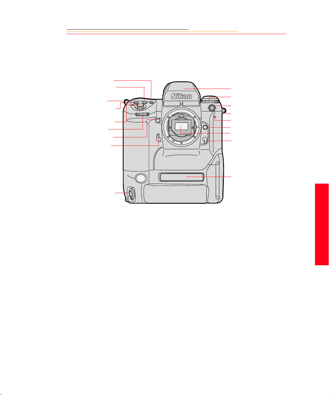
Camera Front
AF Area Mode button
Exposure Mode (MODE)
button
Camera strap eyelet
Exposure Compensat ion
button
Shutter Release button
Sub-Command dial
Depth-of-field Preview
button
Mirror Lockup lever
Viewfinder
Drive Mode /S elf-timer
selector
Sync termin al
Camera strap eyelet
Self-timer LED
Lens Release button
IR filter
Focus Mode selector
Product label
Vertical Shutter release
2
Your Camera
2-3
Page 31

Camera Back
Eyepiece Shutter lever
Finder Release button
Alert LED
Image LCD
OK button
Cancel button
Menu button
Tag/Record button
Back Status LCD
ISO
(
)button
Auto Exposure/Flash
Exposure Bracketing
BKT
(
) button
Shutter Speed/Aperture/
Focus Area Lock
button
L
OK
CANCEL
MENU
TAG/
RECORD
Vie wfinder eyepiece
Auto Exposure/
Autofocus Lock button
AF Start (AF-ON) button
Main-Command dial
Microphone
Four-way switch
Flash Sync Mode
) button
(
Custom Setting Menu
CSM
(
ISO
L CSMBKT
) button
Remote release port
Vertical AF Start (AFON) button
2-4
Page 32

Camera Top
e
Metering System selector
lock release
Metering System selector
Drive Mode selector lo ck
release
Drive Mode/Sel f Timer
selector
Accessory Shoe
Camera Bottom
AF Area Mode button
Power/LCD Panel
O
F
F
O
N
MODE
L
C
S
Illumination switch
Shutter Release button
Power Switch lock releas
Exposure Compensat ion
+/-
button
Exposure Mode (MODE)
button
Top Status LCD panel
Diopter Adjustment knob
2
Tripod mount
Data plate label
Your Camera
2-5
Page 33

Camera Sides
Battery/PC Card door
Battery/PC Card door latch
IEEE 1394 cable po rt (cover not show n)
AC Adapter connecti on (c over not
shown)
2-6
Vertical shutter release lock
Vertical Shutter release
Camera strap eyelet
Page 34

Open Battery/PC Card Door
SERIAL
VIDEO
Battery
Serial port
Card Busy LED
Video Out port
CARD1
CARD2
Eject button (CARD1)
Eject button (CARD2)
2
Your Camera
2-7
Page 35

Viewfinder
1
5
2
3
4
6
7
8
1. Focus area indicators
2. Exposure level (for waist-level finder DW30 or 6x high-magnification finder DW-3i
in manual exposure)
3. Reference circle for Center-weighted
metering
4. Focus brackets/Spot metering
5. Green Ready light
6. Focus indicators: • indicates a subject is in
focus; blinking indicate that autofocus
is impossible; and arrows indicate front
and rear focus respectively
7. Aperture direct readout
8. Focus area indicators
9 10 11 12
13 14 15 16 17
9. Shutter speed lock indicator
10. Aperture lock indicato r
11. Exposure mode
12. Exposure compensation
13. Metering system
14. Shutter speed
15. Aperture
16. Electronic ana lo g exposure display
17. Exposure compensation
2-8
Page 36

LCD Panels
OK
CANCEL
MENU
ISO
BKT
TAG/
AUTO
RECORD
ISO
Top Status LCD
O
F
F
O
N
MODE
LOCK
LOCK
LOCK
+
BKT
L
C
S
SLOW
REAR
CUSTOM
Top Status LCD
+
Image LCD
L CSMBKT
Back Status LCD
Shutter speed l o ck
Shutter speed
Auto Exposure/Flash Exposure
bracketing
Exposure mode
Flexible program
Exposure compensation
Exposure compensation value
LOCK
+
+
BKT
LOCK
LOCK
Aperture lock
Aperture
Focus area lo ck
Focus area/AF area mode
2
Your Camera
2-9
Page 37

Back Status LCD
ISO/Bracketing information/
Custom Setting
ISO Setting mode
Bracketing bar graphs
Auto Exposure/Flash Exposure
Bracketing
White Balance
Frame number
Frames remaining on PC Card
ISO
BKT
AUTO
SLOW
REAR
CUSTOM
Flash sync mode
Personal computer
connection
Custom setting
Card present
Microphone
Battery level
2-10
Page 38

Image LCD
There is a 2-inch diagonal Image LCD on the rear of the camera where you can view
images and change settings.
How the Image LCD Works
You can view images on the Image LCD in a variety of Display modes. You can also
access a variety of options from the Menu bar and from menus which are accessible
through the Menu bar.
Access the options on the Image LCD in a hierarchical manner:
Display mode: Appears when you turn the Image LCD on
Menu bar: Accessible from Display mode
Menus: Accessible from the Menu bar
Turning the Image LCD On
There are two ways to turn the Image LCD on:
✔ Press the OK button to turn the Image LCD on in Display mode
2
✔ Press the Menu button to turn the Image LCD on with the Menu bar (page 2-12) and
the last-used menu displayed.
Turning the Image LCD Off
✔ Press the Cancel button to turn the Image LCD off.
If you turned the LCD on using the OK button and the LCD is not in Display mode,
press the Cancel button more than once.
If you turned the LCD on using the Menu button, pressing the Cancel button once
turns the LCD off without returning to Display mode.
2-11
Your Camera
Page 39

Menu Bar
The Menu bar is available on the Image LCD in any Display mode except Zoom mode
when the Region of Interest box is disabled (page 10-3). The Menu bar contains icons
which access various digital functions.
Folder icon
Menu icon
White Balance icon
Video icon (appears if Vide o is enabled through Main menu )
Contrast icon
Displaying and Navigating the Menu Bar
1 Turn the Image LCD on.
2 Press the Menu button to turn the Menu bar on.
3 Press the left or right side of the Four-way switch to highlight the needed Menu bar
icon.
4 Press the Cancel button or Menu button to turn the Menu bar off.
2-12
Page 40

Making a Menu Selection
1 Navigate the Menu bar (page 2-12) until the Folder or Menu icon is highlighted.
A dropdown menu appears, listing the available options.
2 Press the top or bottom of the Four-way switch to highlight an option.
3 Press the OK button to activate the option.
4 Repeat steps 2 and 3 for any additional menus.
2
Your Camera
2-13
Page 41

Digital Buttons
The Four-way switch and digital buttons activate the digital functions.
Four-way Switch
Menu Button
OK Button
Press the left or right side to:
✔ Navigate through images
✔ Navigate the Menu bar
✔ Move the Region of Interest box (Zoom mode)
Press the top or bottom to:
✔ Change the Display mode
✔ Navigate a dropdown menu
✔ Move the Region of Interest box (Zoom mode)
✔ Toggles the Menu bar off and on
✔ Turns the Image LCD on
✔ Enables the Region of Interest box (Zoom
mode)
✔ Implements a zoom when Region of Interest
box is enabled
✔ Implements a highlighted menu option
✔ Deletes the active image (Delete mode)
✔ Turns the Overexposure indicator on
Cancel Button
Tag/Record Button
2-14
✔ Exits from menus without making any changes
✔ Turns the Image LCD off
✔ Disables t he Region of Interest box (Z oom
mode)
✔ Turns the Overexposure indicator off
✔ Turns the Menu bar off
✔ Tags or untags images when pressed and
released in less than one second
✔ Activates the microphone when pressed and
held for more than one second
Page 42

Quick Guide for Using the Image LCD and Digital Buttons
The digital buttons take on different functions, depending on the current state of the Image
LCD.
Turn the Image LCD on: Press the OK button.
Select a highl ighted menu opt ion: Press the OK but ton.
Enable the Region of Interest box (Zoom
mode):
Implement a zoom (Zoom mode): Press the OK button.
Delete an image (Delete mode): Press the OK button.
Toggle the Menu bar on/off: Press the Menu button.
Turn the Image LCD off: Press the Cancel button.
Dismiss a menu without implementing
change:
Disable the Region of Interest box (Zoom
mode):
Navigate through images in all Display
modes (except Zoom mode when Reg ion of
Interest box is on):
Navigate the Menu bar and d i splay menus: Press the left or right side o f the Four-way
Navigate a dropdown menu: Press the top or bottom of the Four-way
Change to a different display mode: Press the top or bottom of the Four-way
Move the Region of Interest box (Zoom
mode):
Press the OK button.
Press the Cancel button.
Press the Cancel button.
Press the left or right side of the Four-way
switch.
switch.
switch.
switch.
Press any edge of the Four-way switch.
2
Your Camera
2-15
Page 43

Command Dials
Your camera’s Main-Command dial and Sub-Command dial can be used alone or in
combination with other buttons to select various functions or modes.
Main-Command Dial
Use the Main-Command dial by itself or with various buttons to perform the following
functions:
Rotating the Main-Command Dial by Itself
✔ Select the shutter speed in
Shutter-Priority Auto or Manual
exposure mode. Refer to
“Shutter-Priority Auto Exposure
Mode” on page 1 1-1 or “Manual
Exposure Mode” on page 11-8.
AE-L
AF-L
AF-ON
✔ Perform the Flexible Program in
Programmed Auto exposure
mode. Refer to “Flexible
Program” on page 11-13.
2-16
Page 44

Rotating the Main-Command Dial While Pressing Buttons
✔ Select Exposure mode. Refer to
O
F
MODE
F
O
N
✔ Perform Exposure
✔ Select AF area mode. Refer to
✔ Select ISO. Refer to “ISO” on
✔ Select Flash Sync mode. Refer
MENU
“Exposure Mode” on page 6-13.
Compensation. Refer to
“Exposure Compensation” on
page 11-19.
“Selecting AF Area Mode” on
page 7-4.
page 8-9.
to “Flash Sync Mode” on page
9-13.
2
TAG/
RECORD
ISO
Your Camera
L CSMBKT
✔ Select the Custom Setting menu.
Refer to “Custom Settings” on
page 11-32.
✔ Lock shutter speed/aperture/
focus area. Refer to “Locking
Shutter Speed” on page 11 -3.
✔ Set or cancel Auto Exposure/
Flash Exposure Bracketing.
Refer to “Auto Exposure/Flash
Exposure Bracketing” on page
11-24.
2-17
Page 45

Sub-Command Dial
Use the Sub-Command dial by itself or with various buttons to perform the following
functions:
Rotating the Sub-Command Dial by itself
✔ Select the aperture in Aperture-
Priority Auto or Manual
MODE
Exposure mode. Refer to
“Aperture-Priority Auto
Exposure Mode” on page 11-4
or “Manual Exposure Mode” on
page 6-15.
☛ If you are using a non-CPU
lens (without a
microprocessor), you must set
the aperture on the lens’
aperture ring.
Rotating the Sub-Command Dial While Pressing Buttons
2-18
MENU
TAG/
RECORD
ISO
✔ Set the number of exposures and
compensation value in Auto
Exposure/Flash Exposure
Bracketing. Refer to “Auto
Exposure/Flash Exposure
Bracketing” on page 11- 24.
✔ Lock the aperture in A mode and
Shutter speed in S mode. Refer
to “Locking the Aperture” on
page 11-7.
L CSMBKT
✔ Select and make a Custom
Setting. Refer to “Making a
Custom Setting” on page 11-32.
Page 46

Drive Mode/Self-timer Selector
This dual-purpose control allows you to select a Drive mode or set the Self-timer.
When you select a Drive mode, you specify whether one or more images will be captured
when you depress the Shutter Release button.
To set a Drive mode:
Press the Drive mode selector lock
release and rotate the Drive mode/
Self-timer selector. Set S for Singleframe shooting, C
low-speed shooting, C
Continuous high-speed shooting or
C
S for Continuous silent-low-s peed
shooting. Refer to “Drive Mode” on
page 8-10.
C
L
S
C
H
C
L for Continuous
H for
To set the Self-timer:
Press the Drive mode selector lock
2
Your Camera
release and rotate the Drive mode/
Self-timer selector to the (selftimer) position. Refer to “Selftimer” on page 11-28.
C
S
2-19
Page 47

Lens
Refer to Appendix C for a list of lenses that are compatible with your camera.
CAUTION:
Only use lenses that are listed in Appendix C. Other lenses can potentially break
your camera’s IR filter.
Mounting the Lens
1 Remove the camera body cap
and the front and rear lens caps.
2-20
2 Position the lens in the camera’s
bayonet mount so that the
mounting indexes on the lens
and camera body are aligned.
Taking care not to press the lens
release button, twist the lens
counterclockwise until it locks
in place.
When mounting or removing a
lens, make sure that the
camera’s power is turned Off.
Page 48

Setting the Lens to the Minimum Aperture
For Programmed Auto or Shutter-Priority Auto mode, use the minimum aperture lock
lever to lock the lens aperture at f/16.
1 Set the lens to its minimum
aperture (f/16).
2 Slide the lock lever in the
direction of the aperture ring so
that the white dot on the tab
aligns with the orange dot.
Slide the lock lever in the
opposite direction to release the
lock.
☛ Aperture setting operations are
performed using the SubCommand dial. Do not move
the lens aperture once it is set
to its minimum aperture.
☛ The aperture can also be set
with the lens aperture ring in
Aperture-Priority Auto or
Manual Exposure mode. In
these cases the aperture can
only be verified through
aperture direct-readout.
2
Your Camera
2-21
Page 49

Removing the Lens
Press and hold the Lens Release
button and turn the lens clockwise.
☛ If you do not plan to mount a
lens for a while, attach the
supplied BF-1A body cap.
(The BF-1 body cap cannot b e
used on your camera.)
2-22
Page 50

Imager
The imager records light when you capture an image.
Camera Size ISO Range
DCS 760 6 million pixels 80 - 400
DCS 720x 2 million pixels 400 - 4000
IR Filter
Your camera contains an IR filter which maintains proper focus, filters out infrared light,
and helps protect the imager’s coverglass.
You can replace the IR filter with an anti-aliasing filter (available as an accessory). The
anti-aliasting filter improves overall image quality and helps reduce aliasing at certain
focal distances.
2
Your Camera
2-23
Page 51

Viewfinder Diopter
You can compensate for nearsightedness or farsightedness and see more clearly through
the viewfinder by adjusting the finder diopter within a continuous range from –3 to +1.
1 Pull the Diopter Adjustment
knob and rotate it in either
direction until the focused image
in the viewfinder’s reference
circle appears sharp.
2 Push the knob back in to lock.
2-24
Page 52

Illumination Switch
You can illuminate the Top and Back Status LCD panels for easy viewing at night or in
low-light situations.
Rotate the LCD Panel Illumination
O
F
MODE
switch toward the
the T op and Back S t atus LCD
panels.
F
O
N
The LCD panel illumination switch
automatically returns to the on
position, and the LCD panel s
remain illuminated as long as the
meter is on. (You can change the
time that the meter remains on using
custom setting #15. Refer to
“Custom Settings” on page 11-32.)
T o turn the illumination off before it
times out, rotate the LCD Panel
Illumination switch clockwise
again.
After the shutter is released, the
LCD panel illumination
automatically turns off.
to illuminate
2
Your Camera
2-25
Page 53

Mirror Lockup Lever
When using super-telephoto lenses or performing photomicrography, it is necessary to
reduce camera vibration to the absolute minimum.
Lock the reflex viewing mirror in
the up position by rotating the
mirror lockup lever
counterclockwise until it stops.
☛ When the mirror is locked up,
you cannot operate the camera
in any Auto Exposure or
Autofocus mode, even though
the viewfinder LCD may
indicate otherwise. Any
indication of light in the LCD
is a result of light entering
through the viewfinder
eyepiece.
CAUTION:
Do not leave the camera in direct sunlight when the reflex mirror is locked in the
up position. The sunlight may damage the shutter curtain.
2-26
Page 54

Depth-of-Field Preview Button
The depth of field is the zone of acceptable focus in front of and behind the subject. You
can preview this zone using the Depth-of-Field Preview button.
The Depth-of-Field Preview button will not work properly if there is no PC Card inserted.
In Aperture-Priority Auto or
Manual Exposure mode, press the
Depth-of-Field Preview button to
MODE
stop the lens down to the aperture
that was set with the Sub-Command
dial.
In Programmed Auto or ShutterPriority Auto Exposure mode, the
lens will be stopped down to the
automatically set aperture. When
you press the Depth-of-Field
Preview button, the viewed image
becomes progressively darker as the
aperture gets smaller. Those
portions of the image that appear in
focus when the button is pressed are
within the depth of field.
2
Your Camera
Be aware of the following when
using the Depth-of-Field Preview
button:
✔ When using lenses with a meter
coupler, it is not possible to
attain correct exposure because
exposure must be determin ed by
full-aperture metering.
✔ Do not use the Spot Metering
system when using the Depthof-Field Preview button.
✔ During preview, the aperture
cannot be adjusted and
autofocus is not possible.
2-27
Page 55

Accessory Shoe
L
C
S
Sync Terminal
MODE
Located at the top of the MultiMeter Finder , the ISO-type hot shoe
allows direct mounting of a wide
range of NIKON-dedicated
O
F
F
O
N
electronic Speedlights. Refer to
“Attaching the SB-28D or SB28DX Speedlight” on page 9-3.
CAUTION:
Do not use speedlights from
other manufacturers since
higher voltages and/or extra
hot shoe contacts can damage
your camera.
2-28
Your camera features a separate
sync terminal that accepts all flashes
with standard PC-type, plug-in sync
cords.
CAUTION:
Flashes with excessive trigger
circuit voltage can damage
your camera. Consult your
service representative for
questions on compatible
flashes.
Page 56

Self-Diagnostic Shutter System
Your camera is equipped with a selfdiagnostic shutter that automatically
controls the shutter speed for each
release of the shutter.
The self-diagnostic shutter
automatically detects inaccuracies
in performance and readjusts the
shutter speed accuracy for
subsequent image capture.
If a malfunction occurs or the
shutter curtain fails to operate, the
alert LED blinks and
the Top Status LCD panel and
viewfinder. Turn the camera power
Off, then On. Refer to “Turning the
Camera On and Off” on page 3-1. If
the blinking stops, the malfunction
is corrected. If the alert LED and
resume blinking, turn the power off
and take the camera to your service
representative.
Err blinks in
Err
2
Your Camera
2-29
Page 57

Changing Viewfinders
A DP-30 viewfinder is incl uded wit h the D CS 760 C amera. A modi fied D P-30 vi ewfinder
is included with the DCS 720x Camera. See Appendix C for a list of compatible
viewfinders. Using other viewfinders with your camera can decrease the “active area” of
the viewfinder.
Removing the Finder
1 Turn the camera off. Refer to
“Turning the Camera On and
Off” on page 3-1.
2 Press and hold the Finder
Release button.
3 Slide the viewfinder away from
the lens.
2-30
Page 58

Attaching the Finder
Slide the finder in until it clicks in
place.
4 Be sure that the Finder Release
button has returned to its
original position.
IMPORTANT:
Be sure the viewfinder is
attached when you ar e capturing
images. If the shutter is released
without a viewfinder attached,
stray light may enter through the
focusing screen.
When removing a viewfinder, be
careful not to leave smudges or
fingerprints. Place the detached
viewfinder on a soft, clean cloth.
2-31
2
Your Camera
Page 59

Changing Focusing Screens
1 Turn the camera off and remove
the finder. Refer to “Removing
the Finder” on page 2-30.
2 Insert your fingernail under the
rear edge of the focusing screen
and lift the screen out.
3 To install a focusing screen,
insert the front edge under the
central ridge, then push the rear
edge down into place.
IMPORTANT:
When removing a focusing
screen, be careful not to leave
smudges or fingerprints. Place
the detached screen on a soft,
clean cloth.
2-32
Page 60

Camera Straps
A neck strap and a hand strap are included with your camera. You can attach either or
both.
Attaching the Neck Strap
Thread the ends of the neck strap
through the strap fixtures. Pull
firmly on the strap to make sure it is
held securely by the buckles.
2
Your Camera
2-33
Page 61

Attaching the Hand Strap
1 Thread the strap through both
loops in the hand strap pad.
2 Place the three-holed buckle on
the strap and thread through the
camera’s top strap fixture.
3 Thread the other end of the strap
through the camera’s bottom
strap fixture.
4 Thread the top strap back
through the buckle as shown.
5 Thread both ends of the strap
back through the loops on the
hand strap pad.
6 Place the two-holed buckle on
the top strap.
2-34
7 Tuck the top strap through the
bottom loop in the hand strap
pad.
8 Thread the bottom strap through
the two-holed buckle as shown.
9 Tuck the bottom strap through
the top loop in the hand strap
pad.
Page 62

Software Overview
There is a DCS Host Software CD included with your camera. On the CD are two
programs:
✔ KODAK PROFESSIONAL DCS Camera Manager: Allows automatic transfer of
captured images from DCS 700 Series Camera memory to your co mputer when the
camera is connected using the IEEE 1394 interface. You can also view and change
camera properties on the connected camera, and copy or move images to the
computer from a folder on a PC Card in the camera.
✔ KODAK PROFESSIONAL DCS Photo Desk: Allows you to open, edit, process,
and save images captured on a DCS 700 Series Camera after transferring the
images to the computer. You can also save images, then open them directly in
another image editing application.
Refer to the on-line help associated with each program for more information.
Name Plate
The Name Plate property, accessible by the KODAK PROFESSIONAL DCS Camera
Manager, allows you to enter text that appears in certain screens on your camera. The
Name Plate is useful for personalizing your came ra, for exampl e, “This camera belong s to
Joe Smith”.
Refer to the documentation on the included DCS Host Software CD.
2
Your Camera
The text appears in the following screens on the camera’s Image LCD:
✔ No images in folder
✔ No images in memory
✔ No card in camera
2-35
Page 63

Page 64

INSERT
PHOTO
HERE
Powering Your Camera
3
Operate your KODAK PROFESSIONAL DCS 700 Series Digital Camera using either
battery or AC power. You can preserve battery power by using the AC adapter whenever
possible.
You can charge your camera batteries using the included battery charger and international
power cord set. These items are included with your camera and are available from Kodak
as accessories. The power cords allow you to use the AC adapter an d the battery char ger in
Australia, Great Britain, Germany, Japan, and the United States.
Turning the Camera On and Off
O
F
MODE
1 Press and hold the Power Switch
Lock release.
F
O
N
2 While continuing to press the
Power Switch Lock release,
rotate the Power switch
clockwise to turn the camera On
and counterclockwise to turn the
camera Off.
3
Power
3-1
Page 65

Batteries
Your camera can use either Ni-MH (nickel metal hydride) or Ni-Cd batteries. Extended
camera metering, autofocus, or extensive LCD panel operation reduces the number of
images available from a full battery charge.
With a fully charged battery, your camera can provide up to the following number of
images:
Battery DCS 760 DCS 720x
Ni-MH 300 1000
Ni-Cd 100 300
Battery performance deteriorates in temperatures below 32°F (0°C). Keep the camera and
a spare battery close to your body or in an inside pocket to keep it warm until use.
WARNING:
Batteries can explode or cause burns if disassembled, shorted, exposed to high
temperatures, or disposed of in fire. Be sure to observe all precautions indicated on
the battery package. Always keep batteries out of the reach of children.
CAUTION:
If you don’t plan to use your camera for five or more days, remove the battery
from the camera and carrier. This will prevent battery discharge.
3-2
Page 66

Disposing of Batteries
Dispose of discharged batteries in accordance with all applicable local and national
regulations. Utilize established retailer, manufacturer or community battery recycling
programs where they are available. Check the battery for any recycling information.
Consult battery or equipment manufacturers for additional assistance.
3-3
3
Power
Page 67

Inserting/Removing Batteries
☛ You must charge a battery before using it for the first time.
ISO
BKT
AUTO
SLOW
REAR
CUSTOM
1 Check the Card Present icon on
the Back Status LCD panel to be
sure that it is not blinking.
IMPORTANT:
If the Card Present icon or the
Card Busy LED inside the
Battery/PC Card door ar e
blinking, wait until the blinking
stops before conti nu i ng. (You
can lose data if you remove the
battery while the card is busy.)
Turn off the camera before
changing batteries, ot herwise
the camera can “lock up” and
prevent you from doing
anything. If this happens, turn
off the camera, remove the new
battery, wait 10 seconds, insert
the new battery, then turn on the
camera.
3-4
2 Turn the camera off.
Page 68

3 Lift the latch assembly on the
Battery/PC Card door and turn it
counterclockwise to open the
door.
IMPORTANT:
SERIAL
VIDEO
Be sure that the Ca rd Busy LED
is not blinking before you
continue.
3
Power
3-5
Page 69

SERIAL
VIDEO
The white arrow opposite the
connector should be pointing
upwards as the battery is
inserted.
Some (not all) cameras have a
white arrow pointing
downwards (towards the ca mera
bottom) just above the battery
compartment. If your battery
and your camera both have the
arrows, then the arrows should
be aligned as you insert the
battery into the camera.
4 T o insert: slide the battery to the
back of the battery slot an d press
firmly in place.
To remove: slide the battery out
of the battery slot.
5 Close the Battery/PC Card door.
6 Turn the latch assembly
clockwise and return it to its flat
position.
3-6
☛ You can insert or remove a
battery while the camera is
connected to an AC adapter
for camera. Refer to “AC
Adapter for Camera” on page
3-14.
Page 70

Checking Battery Status
You can determine whether a battery needs charging by viewing the Battery icon on your
camera’ s Back St atus LCD panel. (If the camera is using an AC adapter, the Battery icon
is not displayed.)
1 Insert a battery if there is not one
in the camera. Refer to
“Inserting/Removing Batteries”
on page 3-4.
2 Turn the camera on.
ISO
BKT
AUTO
SLOW
REAR
CUSTOM
3 Check the Battery icon on the
Full
☛ If the icon indicates that the
Low
Insufficient
Empty
Always check the battery status at the following times:
✔ When loading a new battery
✔ After lengthy storage
✔ If the shutter will not release
Back Status LCD panel.
The icon indicates whether the
battery needs changing.
battery is empty, the camera
will not capture images.
3
Power
✔ In cold weather
✔ Before an important assignment
3-7
Page 71

Battery Charger
Y o u need to charge a battery before using it for the first time and whenever it is low. If you
plan to use your camera without the AC adapter for an extended period o f time, it is a good
idea to charge one or more batteries before you begin. An external battery charger is
included with your camera.
For the best results, store and use the battery charger within the following temperature
ranges:
Storage temperature range: -25°C to 70°C (-77°F to 158°F)
Charging temperature range: 0°C to 45°C (32°F to 113°F)
The battery charger has two slots. A yellow and a green light near the slots illuminate to
indicate the status of the batteries:
Yellow light Green light Battery Status
Off
On
Off
Slow Flashing
Fast Flashing
* While you can use a battery when the light turns green, you will have optimal results if
you leave the battery in the charger for two hours after the light turns green.
3-8
Off
Off
On *
Off
Off
No battery inserted
Charging
Fully charged
Conditioning (Discharging)
Error
Page 72

Charging Batteries
1 Remove the battery from the
camera (page 3-4).
2 Plug the cable from the AC
adapter for charger into the
battery charger jack.
3 Select the international power
cord that is appropriate for your
area.
4 Insert the appropriate end of the
international power cord into the
receptacle on the rear of the AC
adapter for charger.
5 Plug the power cord into a wall
outlet.
3
Power
3-9
Page 73

ISO
BKT
AUTO
SLOW
REAR
CUSTOM
6 Insert one or two batteries in the
slots in the battery charger.
☛ If you are charging one
battery , yo u can u se either slot.
On average, a battery is charged
in approximately one hour. If
two batteries are inserted, they
are charged simultaneously.
7 Once the green light turns on,
wait two hours, then remove the
batteries from the charger.
If you do not wait, batteries will
only be charged to 80% of
capacity.
8 Insert a charged battery into the
camera.
9 Close the camera door.
The Battery icon is displayed on
the Back Status LCD panel
when a battery is in the camera,
the camera is turned on, and the
camera is not in PowerSave
mode (page 3-12).
☛ The Battery icon is not
displayed if the AC adapter is
connected.
If your battery charger does not function as expected, check the following:
✔ The wall adapter is properly connected.
✔ There are no foreign objects lodged in the pockets.
✔ The batteries are inserted so that they properly mate with the connector in the
bottom of the pocket.
☛ No harm will come to your batteries if you leave them in the charger for an extended
period of time.
3-10
Page 74

Conditioning (Discharging Batteries)
You may occasionally need to condition a battery. You would only do so if a battery
provides a noticeably shorter run time (less than 50% of normal capacity).
IMPORTANT:
Do not condition your batteries too often or they will wear out prematurely.
1 Insert one or two batteries into
the slots on the top of the battery
charger.
2 Press the Condition buttons
associated with the batteries that
you wish to condition.
The batteries will first be
conditioned, then charged. The
whole process can take up to
5 1/2 hours.
3 Remove the batteries from the
battery charger two hours af ter
the green light turns on.
☛ You can condition a battery in one slot while charging a battery in the other.
3
Power
3-11
Page 75

Battery Conservation
Your camera has several built-in fun ctio ns that minim ize drain on your battery.
PowerSave Mode
☛ If your camera is powered by an AC adapter or is connected to a computer with
IEEE 1394 cable, it will not enter PowerSave mode.
If you don’t use your camera for 30 minutes, it will enter PowerSave mode (go to sleep).
In PowerSave mode, the flash is not charged and the backlight fo r the Top Status and Back
Status LCD panels turns off.
☛ You can change the setting for PowerSave time.
Waking your Camera from PowerSave Mode
Lightly press the Shutter Release
button.
O
F
F
O
N
MODE
3-12
Page 76

Image LCD Panel Timeout
The Image LCD panel turns off if you have not used the camera for 60 seconds.
☛ You can change the setting for Image LCD timeout.
Press the OK button to turn the
Image LCD On again.
OK
CANCEL
MENU
Meter Timeout
Your camera’s meter remains on for 8 seconds after you lightly press the Shutter Release
button.
☛ You can change the setting for meter timeout. Refer to “Making a Custom Setting”
on page 11-32.
When the meter times out, the following turn off:
✔ Viewfinder LCD
✔ Top Status LCD panel
Situations Using Extra Battery Power
✔ Use of a telephoto or wide angle fisheye lens and constant auto-focusing
✔ Frequent use of the Image LCD panel
✔ Cold temperatures
✔ Turning the camera on and off frequently
3
Power
3-13
Page 77

AC Adapter for Camera
Use an AC adapter whenever possible to lessen dr ain on the b attery. Y ou should also u se it
when your camera is connected to a computer to prevent loss of power if the battery
should lose its charge.
CAUTION:
Operate the equipment only from the type of power source indicated on the AC
adapter. A line voltage outside of this range can destroy the AC adapter and/or
the camera.
Tips
✔ Use only the KODAK AC adapter; do not plug other chargers or adapters into the
camera.
✔ The AC adapter is for indoor use only.
✔ Do not use the AC adapter for any purpose other than for the camera.
✔ The AC adapter does not have an On/Off switch. To turn off the AC adapter, you
need to unplug it.
3-14
Page 78

Connecting the AC Adapter for Camera
1 Open the connector cover at the
side of the camera.
2 Plug the AC adapter for camera
into the AC Adapter connection.
3 Select the international power
cord that is appropriate for your
area.
3-15
3
Power
Page 79

4 Plug the appropriate end of the
power cord into the AC adapter
for camera.
5 Plug the power cord into a wall
outlet.
☛ You can connect or disconnect
the AC adapter while a battery
is in the camera.
☛ The AC adapter for camera
will
NOT charge a battery in
the camera.
Page 80

INSERT
PHOTO
HERE
Configuring Your Camera
4
This section describes how to change various settings on KODAK PROFESSIONAL
DCS 700 Series Digital Cameras.
Date and Time
You can set the date and time on your camera. The date and time is associated with each
image captured. The format for the date is year/month/day, and the format for time is
hour:minute:second based on a twenty-four-hour clock.
The setting is maintained when you turn the camera off, after PowerSave, or when you
remove the battery for a few days.
☛ There is a small rechargeable battery in the camera which can lose its charge if you
remove the main battery for a long period of time. When you insert the main battery,
the small battery is recharged, but you need to reset the date and time.
4
Configuring
1 Highlight the Menu icon, then
choose Main Menu from the
dropdown menu.
2 Choose Date/Time from the
Main menu.
The Date/Time screen appears.
There are six fields: year , month,
day , a nd hour, minutes, seconds.
3 Press the left or right side of the
Four-way switch to sequence
through the numeric fields.
4 Press the top or bottom of the
Four-way switch to change the
highlighted numeric value.
5 Press the OK or Cancel button.
4-1
Page 81

Camera Properties
You can change the following camera properties to meet your needs:
✔ Delay before Battery Save mode activation
✔ Delay before the Image LCD display turns off
✔ Default folder for image capture
✔ Video format
You can also view the total number of camera actuations.
☛ The list of properties may change as new versions of firmware become available.
The wording in the screens may not be exactly as shown.
Displaying the Properties Menu
✔ Highlight the Menu icon then choose Properties from the dropdown menu.
The Properties menu appears.
4-2
Page 82

Battery Save Onset
4
When your camera is powered by battery, it enters Battery Save state if you do not touch
any controls for the Battery Save Onset time. You can change the onset time from
01:00:00 to 23:59:59 (HH:MM:SS). The default onset time is 60 minutes.
1 Display the Properties menu.
2 Choose Battery Save Onset from the Properties menu.
The Battery Save Onset screen appears.
3 Press the left or right side of the Four-way switch to sequence through the numeric
fields.
4 Press the top or bottom of the Four-way switch to change the highlighted numeric
value.
5 Press the OK or Cancel button.
Display Off Time
Extended use of the Image LCD can drain y our battery. For this reason, the LCD turns off
after the length of time specified in the Display Off Time property. The default Display
Off Time is 60 seconds.
1 Choose Disp lay Off Time from the Properties menu.
The Display Off Time screen appears.
Configuring
2 Press the left or right side of the Four-way switch to sequence through the numeric
fields.
3 Press the top or bottom of the Four-way switch to change the highlighted numeric
value.
4 Press the OK or Cancel button.
4-3
Page 83

Total Actuations
You can determine the number of images captured by your camera from the time of its
manufacture.
1 Choose Total Actuations from
the Properties menu.
The Total Actuations screen
appears, showing the number of
images captured.
2 Press the OK button to dismiss
the screen.
Use Folder 1
You can specify whether the default place to store images is an empty folder or folder 1
when you insert a new PC Card.
1 Choose Use FOLDER01 from
the Properties menu.
The Use FOLDER01 screen
appears.
2 Press the top or bottom of the
Four-way switch to highlight
Yes or No.
4-4
If you select Yes, every time you
replace your PC Card, images
will be stored in folder 1.
If you select No, every time you
replace your PC Card, images
will be stored in the first empty
folder found on the PC Card.
Page 84

Video Format
4
You can specify the format standard used when you view images on an external monitor:
✔ NTSC - North America (default)
✔ PAL - Europe and Asia
1 Choose Video Format from t he Properties menu.
2 Choose NTSC or PAL from the Video Format screen.
3 Press the OK button.
Custom Settings
You can set Custo m Settings using the Custom Settings menu (described below) or the
CSM
button. In general, the method described below is easier to use, since the settings are
labeled. Refer to “Custom Settings Table” on page 11-34.
1 Highlight the Menu icon, and
choose Custom Settings from
the dropdown menu.
2 Choose the desired setting from
the Custom Settings menu.
The selected Custom Setting
screen appears.
3 Choose the desired setting.
Configuring
4 Press the OK button.
4-5
Page 85

Page 86

INSERT
PHOTO
HERE
5
As you capture images, they are stored on a PC Card (PCMCIA card). Before capturing
images, you may want to make a few preparations so that the images will be stored
according to your needs. This chapter describes the use of the PC Card and provides
instructions for storing images.
Using a PC Card
PC Cards
5
Your KODAK PROFESSIONAL DCS 700 Series Digital Camera accepts Type I, Type II ,
or Type III PC Cards which are compatible with the PCMCIA-ATA interface standard.
Most hard disk drive and flash memory cards may be used. Hard disk drive cards will hold
more images and are usually faster than flash memory cards, but flash memory cards are
more rugged.
☛ PC Cards must be ATA-compatible.
CAUTIONS:
Use extreme care when handling PC Cards, as they are easily damaged. If
dropped, a PC Card may be destroyed, resulting in the loss of all data on the card.
PC Card
Do not remove a PC Card from the camera while the Card Present icon on the
Back Status LCD panel or the Card Busy LED inside the Battery/PC Card door
are blinking. The blinking indicates that data is being read from or written to the
PC Card. You may lose data if you remove a card at this time.
5-1
Page 87

Dual Slots for PC Cards
Your camera has two PC Card slots. W ith Type II PC Cards, you can use one or both s lots .
With Type III PC Cards, only one slot can be used. The card in the slot closest to the
camera back is referred to as CARD 1, and the card in the sl ot closest to the camera f ront is
referred to as CARD2.
SERIAL
VIDEO
With one card, you can insert a PC Card in either slot. With two cards, the first card
inserted will be the active card. When you capture or delete images, they will be saved to
or deleted from the active card.
CARD1
CARD2
5-2
Page 88

Inserting/Removing PC Cards
It is not necessary to turn off the camera before inserting or removing a PC Card.
ISO
BKT
AUTO
SLOW
REAR
CUSTOM
1 Check the Card Present icon on
the Back Status LCD panel. It
blinks when a card is busy.
IMPORTANT:
If the Card Present icon is
blinking, wait until it stops
before continuing. You can lose
data if you remove the PC Car d
while it is busy.
2 Lift the latch assembly on the
Battery/PC Card door and turn it
counterclockwise to open the
door.
5
PC Card
5-3
Page 89

IMPORTANT:
SERIAL
VIDEO
Be sure that the Ca rd Busy LED
is not blinking before
continuing.
3 To insert a PC Card: slide it all
of the way into the card slot and
press firmly.
☛ A label inside the door
indicates the proper position
for the card.
5-4
Page 90

4 To remove a PC Card, press the
Eject button and pull the card
out.
5 Close the Battery/PC Card door.
5
PC Card
ISO
BKT
AUTO
SLOW
REAR
CUSTOM
The Card Present icon is
displayed on the Back Stat us
LCD when there is a PC Card in
the camera.
5-5
Page 91

Formatting a PC Card
To prevent formatting the wrong PC Card, there can only be one card in the camera when
you format a card. Format the card using either the quick format or the full format feature.
IMPORTANT:
Quick format, while faster, is not recommended if there is a possibility that there are
defects on the PC Card.
1 Highlight the Menu icon, then
choose Main Menu from the
dropdown menu.
2 Select Card from the Main
menu.
The Card menu appears.
3 Choose Quick Format or Full
Format.
5-6
If two cards are in the camera,
you are prompted to remove the
inactive card. For example, if
CARD2 is active, you are
prompted to remove CARD1.
4 Remove the inactive card, then
select Retry.
If you remove the active card,
the message at the left appears.
5 Re-insert the card in the proper
slot, then select Retry.
Page 92

A confirmation screen appears.
6 Select Yes or No.
If you choose No, the Main
menu appears and the card is not
formatted.
If you choose Yes, the card is
formatted. A Progress screen
appears.
If you chose Full Format and
wait for the progress bar to go to
completion, a full format occurs.
If you press the Cancel button, a
quick format occurs.
With quick format, the card will
be usable, but if there were preexisting problems on the PC
Card, occasional errors may
occur when you save images.
5
PC Card
5-7
Page 93

Selecting a PC Card or Folder
Images are stored in folders on a PC Card. There is always at least one empty folder on
your PC Card. When you store an image in an empty folder, a new empty folder is
automatically created. The new folder is called FolderX, (X being the next number
available).
1 Highlight the Folder icon.
If there is no PC Card in the
camera, an X appears in the
Folder icon. Selecting the icon
produces a menu stating No
Card.
With one PC Card inserted, this
dropdown menu app ears with an
asterisk next to the currently
active folder.
With two PC Cards inserted, this
dropdown menu appears with
asterisks next to the currently
active card and folder.
A 1 or 2 appears in the Folder
icon, indicating the active card.
5
PC Card
The listed folders are on the
active card. The folder list
changes when you change cards.
The numbers in pare ntheses next
to the cards and folders indicate
the number of images in each.
2 With two PC Cards inserted,
select CARD1 or CARD2, then
select a folder. With one card
inserted, select a folder.
5-8
Page 94

INSERT
PHOTO
HERE
Controlling Exposure
6
This chapter describes the functions available for controlling exposure in your camera.
White Balance
The KODAK PROFESSIONAL DCS 700 Series Digital Camera offers both Preset and
Custom White Balance functionality. There are five Preset options: Auto, Daylight,
Tungsten, Fluorescent, and Flash.
With Custom White Balance, you can save White Balance settings using your camera or
the KODAK PROFESSIONAL DCS Photo Desk software (Photo Desk) then reuse the
settings on subsequently captured images. You can also delete White Balance settings
when they are no longer needed.
6
Exposure
☛ Refer to the Photo Desk documentation for instructions on saving the settings using
the software.
This feature saves you time if you repetitively work under the same lighting conditions.
For example, if you frequently work in an indoor stadium with a particular type of
lighting, you can name and save a White Balance setting for reuse.
When you select a white balance option, you identify the type of lighting used to capture
an image. For example, if you capture an image in daylight, you would set the white
balance to daylight for the best results.
IMPORTANT:
White balance affects how your color image is captur ed. If you use an incor rect setting,
you may not get optimal results.
6-1
Page 95

ISO
SLOW
REAR
To determine the current white
balance setting, check the White
Balance icons on the Back LCD.
BKT
AUTO
CUSTOM
If a flash is attached to your
AUTO
Auto - Flash
camera and you choose Auto
mode, the Auto Flash icons
appear.
Flourescent
Daylight
Tungsten
Flash
Custom
The table below shows the predicted color temperature at each White Balance setting:
White Balance
Setting
Color T emperature
(Degrees Kelvin)
Daylight 5500
Tungsten 3200
Fluorescent 5000
On-Camera Flash 5600
6-2
Page 96

6
Choosing a White Balance Setting
ISO
BKT
AUTO
SLOW
REAR
CUSTOM
Exposure
1 Highlight the White Balance
icon.
The White Balance menu
appears. An asterisk appears
next to the current setting.
2 Choose a Preset option or a
Custom setting.
You can also choose Custom
WB Setup (page 6-4).
3 Press the OK button to select the
option or the Cancel button to
return to the previous screen
without changes.
If you choose a Custom White
Balance setting, no icons appear
in the Back Status LCD.
6-3
Page 97

Custom White Balance Setup
When you choose Custom WB Setup from the White Balance menu, the following options
are available:
✔ Choose the currently selected image as the White Balance setting (see below)
✔ Choose a previously loaded White Balance setting
✔ Delete previously loaded White Balance settings
✔ Load a White Balance setting from a PC Card
✔ Save settings from the current image
1 Choose Custom WB Set up fro m
the White Balance menu
(page 6-3).
If there are no images in the
currently selected folder, this
screen appears.
If the selected folder contains
images, this screen appears,
showing the current image.
6-4
2 Do one of the following:
Press the OK button to save the
White Balance values from the
current image. The setting is
saved with the same name as the
image and overwrites the setting
saved the last time you chose
OK. (This setting will be
overwritten the next time you
repeat this process.)
Press the Cancel button to return
to the previous screen without
changing settings.
Press the Menu button (see next
page.)
Page 98

6
If you pressed the Menu button,
the Custom WB menu appears.
3 Choose one of the following:
✔ A previously loaded White
Balance setting (listed at the
top of the menu)
✔ Delete WB Setting
✔ Load from Card (page 6-6)
✔ Save the setting from the
current image (page 6-8)
Deleting White Balance Settings
You can delete White Balance settings from your camera. Your camera can store a
maximum of ten settings, and you may need to delete unused settings to make room for
new ones.
1 With the Custom WB menu
displayed, choose Delete WB
Setting.
The Delete White Balance
Setting menu appears.
Exposure
2 Choose the setting to be deleted.
A confirmation screen appears.
3 Press the OK button to delete the
setting, or the Cancel button to
leave it intact.
6-5
Page 99

Loading White Balance Settings
You can load White Balance settings from a PC Card into your camera. (The settings are
saved to the card using the DCS Host software.)
1 With the Custom WB Menu
displayed, choose Load from
Card.
The Load White Balance Setting
screen appears with a list of the
White Balance settings on the
active PC Card. (If only one
card is in the camera, the card
choices do not appear.)
2 Choose the desired card. (You
may need to scroll up to the card
choices if there are numerous
White Balance settings.)
3 Repeat step 2 to choose the
desired Custom White Balance
setting.
6-6
4 Press the OK button.
Barring conditions described on
the next page, the setting is
loaded from the PC Card to your
camera.
☛ The last setting loaded
becomes the active White
Balance setting.
Page 100

Under the following conditions, White Balance settings cannot be loaded.
Condition Error Message Solution
6
Exposure
You attempt to load s ettings
into a camera that was not
used to capture the image from
which the setting was saved.
(The camera must have same
serial number).
You attempt to load a setting
with the same name as one on
your camera.
Each setting that you load
must have a unique name.
You attempt to load a setting
when there are already ten
settings on your camera.
Your camera holds up to ten
Custom White Balance
settings.
Select a setting from an
image captured on your
camera.
Rename the setting on the
PC Card or overwrite an
existing file with a file of
the same name.
Delete unwanted settings
from the camera so that
others can be loaded.
6-7
 Loading...