

Page 1

DCS 600 Series Digital Cameras
User’s Guide
for DCS 600 Series Digital Cameras
Page 2

© Eastman Kodak Company and Nikon Corp., 2000 All rights reserved
Kodak and Kodak Professional are trademarks of Eastman Kodak Company
Adobe, Photoshop, and Acrobat are trademarks of Adobe Systems Inc.
Page 3

CAREFULLY READ THE FOLLOWING WARRANTY TERMS AND CONDITIONS
BEFORE USING YOUR CAMERA. USE OF YOUR CAMERA INDICATES YOUR
ACCEPTANCE OF THESE TERMS AND CONDITIONS. IF YOU DO NOT AGREE
WITH THEM, PROMPTLY RETURN THE CAMERA, UNUSED, ALONG WITH THE
ACCOMPANYING MATERIALS, IN THE ORIGINAL PACKAGING.
WARRANTY
KODAK PROFESSIONAL DCS 600 Series Cameras
THIS WARRANTY APPLIES ONLY TO EQUIPMENT PURCHASED IN THE
UNITED STATES.
Warranty Time Period
Kodak warrants your KODAK P ROFESSIONAL DCS 600 Series Camera to be free from
defects in material and workmanship for 1 year or 100,000 shutter activations from the
day of purchase (whichever comes first).
Warranty Repair Coverage
If this equipment does not function properly during the warranty period due to defects in
material or workmanship, Kodak will, at its option, either repair or replace the equipment
without charge, subject to the condit io ns and limitations stat ed he rei n. Suc h repair service
will include all labor as well as any necessary adjustments and/or replacement parts.
If replacement parts are used in making repairs, these parts may be remanufactured, or
may contain remanufactured materials. If it is necessary to replace the entire system, it
may be replaced with a remanufactured system. Repair or replacement carries a 30 day
warranty ef fecti ve at the ti me of ser vice prob le m resolut ion. This warran ty wil l not exte nd
the original warranty period, and in the case of parts replacement, will only apply to parts
and labor performed to repair the equipment.
Page 4

Limitations
REPAIR OR REPLACEMENT WITHOUT CHARGE IS KODAK’S ONLY OBLIGATION
UNDER THIS WARRANTY.
Warranty service will not be provided without dated proof of purchase. Please return
the Warranty Registration card within 30 days of purchase.
As a condition of warranty service, before sending in your equipment to a Kodak
authorized service center for repair, you must first contact a Kodak representative for
return authorization and instructions.
Should you need to return equipment to Kodak, Kodak is not responsible for the loss or
damage of equipme nt whil e i n t ra nsport to a Kodak author ized service center. You may, at
your option, choose to insure equipment for loss or damage with the carrier of your
choice.
This warranty becomes null and void if, during shipment, you fail to pack your Kodak
Professional DCS 600 Series Digital Camera in a manner consistent with the repacking
instructions.
This warranty does not cover the following:
Circumstances beyond Kodak’s control
✔
Service or parts to correct problems resulting from the use of attachments,
✔
accessories or alterations not marketed by Kodak
Unauthorized modifications or service
✔
Misuse
✔
Abuse
✔
Failure to follow Kodak’s operating, maintenance, or repacking instructions
✔
Failure to use Kodak supplied items (such as cables).
✔
KODAK MAKES NO OTHER WARRANTIES, EXPRESS OR IMPLIED, AND
SPECIFICALLY DISCLAIMS THE IMPLIED WARRANTIES OF MERCHANTABILITY
AND FITNESS FOR A PARTICULAR PURPOSE.
KODAK WILL NOT BE RESPONSIBLE FOR ANY CONSEQUENTIAL OR INCIDENTAL
DAMAGES RESULTING FROM THE PURCHASE, USE, OR IMPROPER FUNCTIONING
OF THIS EQUIPMENT EVEN IF THE LOSS OR DAMAGE IS CAUSED BY THE
NEGLIGENCE OR OTHER FAULT OF KODAK. SUCH DAMAGES FOR WHICH
KODAK WILL NOT BE RESPONSI BLE INCLUDE, BUT ARE NOT LIMITED TO, LOSS
OF REVENUE OR PROFIT, DOWNTIME COSTS, LOSS OF USE OF YOUR CAMERA,
COST OF ANY SUBSTITUTE EQUIPMENT, FACILITIES, OR SERVICES, OR CLAIMS
OF YOUR CUSTOMERS FOR SUCH DAMAGES.
Page 5

Outside the United States
In countries other than the United States, warranty terms may be different. Unless a
specific Kodak warranty is communicated to the purchaser in writing by Kodak, no
warranty or liability exists even though defect, damage or loss may be by negligence or
other act of Kodak.
How to obtain service
In the United States, call 1-800-23-KODAK (1-800-235-6325).
In Canada, call 1-800-GO-KODAK (1-800-465-6325).
In other countries, call your nearest Kodak representative.
If service is required, your Kodak representative will instruct you to return the unit to the
nearest service center for repair and will issue a return authorization number.
When returning a KODAK PROFESSIONAL DCS 600 Series Camera for repair, the unit
should be packed in its original packing materials according to the repacking instructions
located on the shipping container. The problem report form, located at the back of this
manual, should also be completed and enclosed with your camera. If the original
packaging has been discarded or is not available, packing will be the purchaser’s
responsibility.
Retur n of the repair ed or replaced equipment to the customer can be expected five to
seven business days from the date the equipment arrives at the service center.
Page 6

Product Support Options
During the warranty period for the Kodak Professional DCS 600 Series digital camera,
you are entitled to pr oduc t support for both hardware and sof twa re , provi ded your camera
is registered with the Eastman Kodak Company. You may register with Eastman Kodak
via mail, fax, or through Kodak’s WWW (World Wide Web) site
(http://www.kodak.com).
Support is provided through a variety of options:
1 Technical support through the WWW site: (http://www.kodak.com):
Support includes FAQs (Frequently Asked Questions), downloadable software
✔
updates, and technical topic articles for reading and downloading.
2 FaxBack Documents on a variety of subjects. The FaxBack system is available at the
following phone number:
North America 1-800-508-1531
3 Authorized Dealers:
Contact your authorized Kodak Professional dealer for help with camera operation
and connection to your computer. Many dealers can also provide training for your
graphics applic ation soft ware, inte gration consulti ng, and support ing equip ment such
as Kodak DS8650 PS Dye Sublimation Printers. Authori zed dealers can als o provide
help in purchasing a service maintenance agreement.
4 Telephone Support:
Currently, telephone supp ort is pr ovided without cha rg e during you r warrant y perio d
only. Your camera must be registered with Eastman Kodak to qualify for no-charge
support. You will be asked to provide the serial number of your camera and proof of
purchase may be requested to verify the current status of your warranty. Cameras
found to be out of warranty will require a credit card payment for each call incident.
There is no charge to register your camera with Eastman Kodak Company.
United States: Call 1-800-23-KODAK (1-800-235-6325)
Outside United States: Contact your local Kodak service representative
Page 7

5 Out-of-Warranty Support Options
There will be a charge for call incidents if you wish to speak to a Kodak support
representative. A call incident is defined as only those issues raised during the first
telephone o r emai l co ntact . F ollow- up te lephone cal ls by Kod ak’s represe ntati ve, an d
callbacks to Kodak’s Support Center to resolve the call incident will not be charged,
provided a valid, active call number is provided. Calls to report bugs or anomalies
will have any charges cancelled. Calls to arrange for service will have the charges
cancelled or applied as a credit against the repair estimate or invoice.
Service maintenan ce a greement s, which cove r the r epair and suppo rt of t he DCS 600
Series camera and software are available. Please contact the regional Service
Marketing group at:
North America 1-800-645-6325
No-charge options include:
• Kodak Professional World Wide Web site:
http://www.kodak.com/go/support
• FaxBack system docum ents
• Kodak Professional dealer where you purchased this product.
Page 8

Table of Contents
Important Information ..................................................1-1
System Requirements for your Computer................................................ 1-2
Macintosh ........................................................................................ 1-2
Windows ..........................................................................................1-2
Warnings...................................................................... ........ .................... 1-3
Important Safeguards and Precautions..................................................... 1-4
Electromagnetic Emissions ...................................................................... 1-7
VCCI Statement....................................................................................... 1-7
About Your Camera .....................................................2-1
Nomenclature............ ................................................... ........ .................... 2-3
Camera Front ...................................................................................2-3
Camera Back ...................................................................................2-4
Contents
Camera Top ..................................................................................... 2-5
Camera Bottom ................................................................................2-5
Camera Sides ...................................................................................2-6
Open Battery/PC Card Door ............................................................2-7
Viewfinder ................................. ......... .................................................. ... 2-8
Navigate Switch....................................................................................... 2-9
Using the Navigate switch to Navigate the Image LCD Panel ....... 2-9
Using the Navigate switch to Select the Focus Area .......................2-9
Digital Function Buttons........................................................................ 2-10
LCD Panels............................................................................................ 2-11
Page 9

Top Status LCD Panel ...................................................................2-11
Back Status LCD Panel ................................................................. 2-12
Image LCD Panel .......................................................................... 2-12
Menu Bar ..............................................................................2-12
Navigation Techniques ......................................................... 2-14
Status Bar ..............................................................................2-16
Command Dials ..................................................................................... 2-17
Main-Command Dial ....................................................................2-17
Rotating the Main-Command Dial by Itself .........................2-17
Rotating the Main-Command Dial While Pressing Buttons 2-18
Sub-Command-Dial ......................................................................2-19
Rotating the Sub-Command Dial by itself ...........................2-19
Rotating the Sub-Co mmand Dial Wh ile Pressing Buttons: . 2-19
Drive Mode/Self-Timer Selector........................................................... 2-20
Lens........................................................................................................ 2-21
Mounting the Lens ........................................................................2-21
Setting the Lens to the Minimum Aperture ...................................2-22
Removing the Lens .......................................................................2-24
Imager.................................................................................................... 2-25
Anti-aliasing filter.................................................................................. 2-25
IR Filter.................................................................................................. 2-25
Viewfinder Diopter................................................................................ 2-26
Illumination Switch................................... ............................................. 2-27
Mirror Lockup Lever............................................................................. 2-28
Depth-of-Field Preview Button ............................................................. 2-29
Accessory Shoe...................................................................................... 2-30
Page 10

Sync Terminal........................................................................................ 2-30
Self-Diagnostic Shutter System ............................................................. 2-31
Changing Viewfinders........................................................................... 2-32
Removing the Finder .....................................................................2-32
Attaching the Finder ......................................................................2-33
Changing Focusing Screens................................................................... 2-34
Camera Straps........................................................................................ 2-35
Attaching the Neck Strap .............................................................. 2-35
Attaching the Hand Strap ..............................................................2-36
Name Plate............................................................................................. 2-37
Poweri ng Y o u r C am e ra ............................. .. .. ... ............3-1
Turning the Camera On and Off.............................................................. 3-1
Batteries .................... ......... ........ ................................................... ........ ... 3-2
Inserting/Removing Batteries ..........................................................3-3
Checking Battery Status ..................................................................3-6
Battery Charger........................................................................................ 3-7
Charging Batteries ..........................................................................3-8
Conditioning (Discharging Batteries) ...........................................3-10
Contents
Battery Conservation ............................................................................. 3-11
PowerSave Mode ...........................................................................3-11
Waking your Camera from PowerSave Mode ...................... 3-11
Image LCD Panel Timeout ............................................................ 3-12
Meter Timeout ...............................................................................3-12
Situations Using Extra Battery Power ...........................................3-12
AC Adapter for Camera......................................................................... 3-13
Connecting the AC Adapter for Camera ....................................... 3-14
Page 11

Configuring Your Camera ...........................................4-1
Date and Time.......................................................................................... 4-1
Camera Properties.................................................................................... 4-3
Setting Display Off Time ................................................................4-3
Setting PowerSave Time .................................................................4-3
Enabling Sharpening .......................................................................4-4
Setting File Resolution .................................................................... 4-5
Determining Total Actuations ......................................................... 4-6
Use Folder 1 ............................................................................ 4-6
Custom Settings....................................................................................... 4-7
Using a PC Card ..........................................................5-1
PC Cards .................................................................................................. 5-1
Dual Slots for PC Cards ..................................................................5-2
Inserting/Removing PC Cards .........................................................5-3
Formatting a PC Card ......................................................................5-6
Selecting a PC Card or Folder .........................................................5-8
Saving Files .................................................................6-1
JPEG and TIFF File Processing............................................................... 6-1
Processing with Two PC Cards .......................................................6-1
Processing Images ..................................................................... ......6-2
Changing Processing Settings ......................................................... 6-5
Working with TIFF Custom Files on your Computer ..................... 6-7
IPTC Data Management .......................................................................... 6-8
Loading IPTC Data from a PC Card ...............................................6-9
Quick Start ...................................................................7-1
Before You Start...................................................................................... 7-1
Page 12

The AC Adapter for Camera ...........................................................7-5
Connecting the AC Adapter for Camera ................................ 7-5
Optional Settings Before You Start ......................................................... 7-7
Set the Date and Time .....................................................................7-7
Select a PC Card or Folder .............................................................. 7-7
Basic Shooting......................................................................................... 7-8
Reviewing Images on Your Camera...................................................... 7-13
Setting Display Contrast ................................................................7-14
Setting Display Options ................................................................7-15
Tagging Images...................................................................................... 7-17
Deleting Images ........................................................... ........ .................. 7-18
Deleting a Single Image ................................................................ 7-18
Deleting More Than One Image ....................................................7-19
Associating a Sound File with an Image................................................ 7-20
Controlling Exposure ...................................................8-1
Contents
White Balance.......................................................................................... 8-1
Selecting Custom White Balance .................................................... 8- 3
Using White Balance Settings .........................................................8-4
Selecting White Balance Settings ...........................................8-6
Deleting White Balance Settings ............................................8-6
Loading White Balance Settings ............................................ 8-7
Saving White Balance Settings using your Camera ...............8-9
Saving White Balance Settings using the Computer ..............8-9
Exposure Metering System.................................................................... 8-10
3D Color Matrix Metering .......................................................... ..8-10
Center-Weighted Metering ............................................................8-11
Spot Metering ................................................................................8-12
Page 13

Setting the Metering System .........................................................8-13
Exposure Mode...................................................................................... 8-14
Programmed Auto Exposure Mode ......................................8-14
Shutter-Priority Auto Exposure Mode ..................................8-15
Aperture-Priority Auto Exposure Mode ............................... 8-15
Manual Exposure Mode ........................................................ 8-16
Setting Exposure Mode ................................................................. 8-17
Focusing ... .. ..... ..... .... ..... .. ..... .... ..... .. ..... .... ..... .. ..... .... .... 9- 1
Focus Area................................................ ............................................... 9-1
Selecting the Focus Area .................................................................9-1
Locking the Focus Area ..........................................................9-3
Selecting AF Area Mode .................................................................9-4
Focus Mode....................................... ........ ......... ...................................... 9-6
Autofocus ........................................................................................ 9-6
Single Servo AF with Focus-Priority (Stationary Subject) ....9-7
Single Servo AF with Focus-Priority (Moving Subject) ........ 9-8
Continuous Servo AF with Release-Priority ..........................9-9
Manual Focus ................................................... ......... ....................9-10
Manual Focus with the Electronic Rangefinder ................... 9-11
Manual Focus Using a Clear Matte Field ............................9-13
Special Focusing Situations in AF......................................................... 9-13
Antialiasing Filter or IR Filter: Effect on Focus.................................... 9-15
Sharpening............................................................................................. 9-16
Capturing Images .......................................................10-1
Preparing to Capture an Image.............................................................. 10-1
Basic Shooting....................................................................................... 10-3
Page 14

Two-Button Reset ..........................................................................10-8
ISO......................................................................................................... 10-9
Drive Mode.......................................................................................... 10-10
Choosing a Drive Mode ..............................................................10-10
Single-Frame Shooting .......................................................10-11
Continuous Shooting ..........................................................10-12
Using the Vertical Controls ................................................................. 10-13
Intervalometer...................................................................................... 10-14
Flash Photography ................................................ .....11-1
Recommendations for Flash Photography............................................. 11-1
Auto Aperture Mode.............................................................................. 11-2
Attaching the SB-28D or SB-28DX ...................................................... 11-3
Turning on the SB-28D or SB-28DX .................................................... 11-3
Standby Mode........................................................................................ 11-4
Enabling/Disabling Standby Mode ...............................................11-4
Waking the SB-28D or SB-28DX from Standby mode. ...............11-4
Contents
Setting Up Your Camera for Flash Photography................................... 11-5
Setting Up the SB-28D or SB-28DX..................................................... 11-7
Test Firing.............................................................................................. 11-9
Using the SB-28D................................................................................ 11-10
Auto Flash Distance Range.................................................................. 11-11
Flash Sync Mode.................................................................................. 11-13
Slow Sync ........ ......... .................................................. ......... ........11-13
Making a Dark Background More Visible .........................11-13
Rear Curtain Sync .......................................................................11-15
Page 15

Creating a Natural-looking Stream of Light ....................... 11-15
Guide Numbers for Determining the Correct Aperture....................... 11-17
Calculating the Correct Aperture ................................................ 11-17
Calculating the Shooting Distance .............................................. 11-17
Guide Number Table ................................................................... 11-17
Working with Images on the Camera ........................12-1
Image Review Mode.............................................................................. 12-1
Setting the Review Mode ..............................................................12-2
Reviewing Images ........................... ......... ........ .............................12-3
Navigating in Single Image Review Mode ...................................12-3
Navigating in Four or Nine Image Review Mode .........................12-3
Navigating Horizontally .......................................................12-4
Navigating Vertically ........................................................... 12-5
Adjusting Display Contrast.................................................................... 12-6
Selecting an Image................................................................................. 12-7
Setting Display Options......................................................................... 12-8
Tagging Images.................................................................................... 12-10
Associating Sound Files With Images................................................. 12-11
Deleting Images................................................................................... 12-13
Deleting a Single Image ..............................................................12-13
Deleting More Than One Image ................................................. 12-14
Recovering Deleted Images................................................................. 12-15
Advanc ed O p er at i o n ..................................................13-1
Capturing Images in Each Exposure Mode ........................................... 13-1
Shutter-Priority Auto Exposure Mode ..........................................13-1
Locking Shutter Speed .......................................................... 13-3
Page 16

Aperture-Priority Auto Exposure Mode ........................................13-4
Locking the Aperture ............................................................ 13-7
Different Procedures for Different Lenses ...........................13-8
Manual Exposure Mode ................................................................13-8
Locking Shutter Speed/Aperture ........................................ 13-11
Different Procedures for Different Lenses .........................13-12
Flexible Program.................................................................................. 13-13
Focus Lock For Off-center Subjects.................................................... 13-14
AE/AF Lock......................................................................................... 13-16
About AE Lock ........................................................................... 13-17
Exposure Compensation...................................................................... 13-19
Obtaining the Meter Reading in Manual Exposure Mode ..........13-20
Exposure Compensation Function ...............................................13-22
Auto Exposure/Flash Exposure Bracketing ................................13-24
Self-Timer............................................................................................ 13-28
Long Time Exposure............................................................................ 13-30
Contents
Custom Settings................................................................................... 13-32
Making a Custom Setting ............................................................13-32
Reset Factory Settings ................................................................. 13-33
Custom Settings Table ................................................................13-34
Connecting to Your Computer ...................................14-1
Advantages to using an IEEE 1394 Connection ...........................14-1
Advantages to using a Card Reader .............................................. 14-1
Connecting Your Camera to the Computer ........................................... 14-2
Quitting—Disconnecting from the Computer ....................................... 14-4
Using the Card Reader........................................................................... 14-4
Page 17

Transmitting Data ...................................................... 15-1
Connecting a Device to the Serial Port.................................................. 15-1
Accessing Serial Port Options............................................................... 15-2
Setting the Baud Rate .................................................................... 15-2
Serial In Mode ...............................................................................15-3
Serial In Status ..............................................................................15-4
Serial Out Mode ............................................................................15-5
Image Transmit...................................................................................... 15-6
Camera Care ..............................................................16-1
Handling................................................................................................. 16-1
Cleaning................................................................................................. 16-2
Anti-aliasing Filter and IR Filter ........................................................... 16-3
Removing, Cleaning, and Re-installing the Anti-aliasing or IR Filter 16-3
The Imager............................................................................................. 16-5
Determining if the Imager is Dirty ................................................ 16-5
Cleaning the Imager ......................................................................16-8
Reassembling the Camera ................................................. ............ 16-8
Storing.................................................................................................... 16-9
Top and Back Status LCD panels.......................................................... 16-9
Installing Camera Firmware on Your Computer................................. 16-10
Updating Camera Firmware............................... ........ ......... ................. 16-10
Updating From the PC Card ............ ......... ...................................16-11
Appendix A - Specifications .......................................A-1
Appendix B - Troubleshooting ................................... B-1
Page 18

Other symptoms, causes and remedies:.................................................. B-3
Appendix C - Lens and Viewfinder Compatibility .....C-1
Compatible Lenses.................................................................................. C-1
Manual Single Focal Length Lenses .............................................. C-1
Manual Zoom Lenses ..................................................................... C-5
Autofocus Single Focal Length Lenses .......................................... C-6
Autofocus Zoom Lenses ................................................................. C- 7
Compatible Viewfinders......................................................................... C-9
Appendix D - Glossary ...............................................D-1
Appendix E - Problem Report .....................................E-1
Appendix F - Remote Control Accessories ................ F-1
Contents
Page 19

INSERT
PHOTO
HERE
1
Important Information
Thank you for purchasing your new KODAK PROFESSIONAL DCS 600 Series Camera
(DCS 620, 620x, 660, or 660M). This portable camera system, which combines
technologies of Eastman Kodak Company and Nikon Corporation, will allow you to take
and store high-resolution, high-quality digital images. Before you start using the camera,
you should follow the instructions listed below.
✔ Read the Warranty statement.
✔ Read the Software License Agreement.
✔ Verify that your camera package contains everything mentioned in the list of
Package Contents.
✔ Verify that your Macintosh or PC meets the system requirements.
✔ Read the Warnings section.
✔ Review the Important Safeguards and Precautions.
✔ Send in the Warranty registration card.
1
Important Info
1-1
Page 20

System Req uirements for your Computer
The following sections list the required and optional computer hardware and software
needed to run the DCS Host Software with Adobe Photoshop on the Macintosh, and
TWAIN-compliant applications on the PC. Refer to the KODAK PROFESSIONAL DCS
Host Software User’s Manual on the DCS Host Software CD included with your camera.
Macintosh
✔ 100 MHz Power PC processor wit h on- boar d I EEE 1394 port and/or available PCI
bus slots and/or PC Card reader
✔ IEEE 1394 adapter cards (if tethering camera without on-board IEEE 1394 port)
✔ Macintosh OS 8.1or later system software (Macintosh OS 8.5.1 or later for a
tethered camera)
✔ 64 MB RAM minimum allocated to Photoshop
✔ 200 MB minimum free hard disk space
✔ 15 inch or larger color display (24-bit recommended)
✔ Adobe Photoshop software version 4.0, 4.01, 5.0, or 5.5 (or software that supports
Photoshop Acquire Plug-ins)
Windows
✔ Personal computer with a 100 MHz Pentium processor with on-board IEEE 1394
port and/or PCI bus slots available and/or PC Card reader
✔ IEEE 1394 adapter cards (if tethering camera without on-board IEEE 1394 port)
✔ Windows 2000, Windows 98, or Windows NT 4.0 or later system software
✔ 64 MB RAM minimum
✔ 200 MB minimum free hard disk space
✔ Color display ca pab le of 640 x 48 0 pixel resolution (or gr eat er ) True color (24-bi t)
is recommended
✔ Version 1.7 TWAIN-compliant software application such as Adobe Photoshop
software version 4.0, 4.01, 5.0, or 5.5
1-2
Page 21

Warnings
✔ To prevent fire or shock hazard, use only the recommended accessories and
attachments.
✔ Use extreme care when ha ndlin g PC Cards, as the y are ea sily da maged. If dro pped,
the PC Card may be destroyed, resulting in the loss of all data on the card.
✔ Do not remove a PC Card, battery, or AC adapter from the camera while the Card
Present icon on the Back Status LCD panel or the Card Busy LED inside the
Battery/PC Card door are blinking. The blinking indicates that data is being read
from or written to the PC Card. You may lose data if you remove a card at this
time. Refer to “Inserting/Removing PC Cards” on page 5-3.
1
ISO
BKT
AUTO
SLOW
REAR
CUSTOM
PC Card icon
✔ You should operate your camera only from the type of power source indicated on
the name plate of the AC adapter. A line voltage outside this range can destroy the
AC adapter and/or the camera.
✔ Use only the AC adapter (either included with your camera or available from
Kodak as an accessory). Do not plug other adapters into the camera.
✔ The AC adapter is for indoor use only.
✔ Do not use the supplied AC adapter for any purpose other than for the DCS 600
Series camera.
✔ The Battery/P C Card doo r shoul d always be close d when you a re usi ng the camera.
If a shock is applied to the camera, the battery may fall out causing loss of data if
an image is currently being saved to the PC Card.
Important Info
1-3
Page 22

Important Safeguards and Precautions
The exclamation point in an equilateral triangle is in tended to
alert the user to the presence of important operating and
maintenance (servicing) instructions in the literature accompanying
your camera.
✔ Read Instructions—Read all the safety and operating instructions before
operating your camera.
✔ Follow Instructions—Follow all operating and usage instructions.
✔ Controls—Adjust only those controls that are covered by the operating
instructions.
✔ Heed Warnings—Heed all warnings on your camera and in the operating
instructions.
✔ Retain Instruct io ns and Packag ing— Retai n the sa fet y and oper atin g in struc tions
for future reference. Retain the packing case for use if your camera n eeds to be
shipped.
✔ Handling—Handle your camera with care. Treat the imager and the anti-aliasing
filter as you would your best lens. Do not drop your camera. Do not place your
camera on an unstable cart, stand, bracket, or table. It can fall, causing serious
injury to persons and serious damage to your camera.
✔ Dust—If you operate the camera in environments with excessive dust levels, dust
may accumulate on the camera.
✔ Water and Moisture— Do n ot us e the camera in heavy ra in or near salt spray and
do not immerse your camera in water or other liquids. Do not use the AC adapter
near water—for example, near a sink, or in a wet room or basement.
1-4
Page 23

✔ Object or Liquid Entry—Never push foreign objects of any kind into your
camera openings. The objects could touch dangerous voltage points or short out
parts and cause a fire or electric shock. Never spill liquid of any kind on your
camera.
✔ Attachments—Do not use atta chmen ts tha t are no t recommen ded. The use of such
attachments may cause hazards and serious damage to your camera.
✔ Power Sources—Operate your camera only from the type of power source
indicated on the name pl ate of t he AC adap ter. If you are not sure of the typ e of AC
power that will be used, consult a dealer or local power company.
✔ Overloading—Do not overload power outlets and extension cords; this can result
in a risk of fire or electric shock.
✔ Cables—Do not use cab le s othe r tha n thos e suppl ied wi th t he camer a. Use only t he
IEEE 1394 cable supplied with your camera to attach the camera to the computer.
If you use other cables, you may violate FCC emission requirements.
✔ Power-Cord Protections—Route power-supply, and other cords, so that you are
not likely to walk on them or pin ch them with items place d on or aga inst th em. Pay
particular attention to cords at plugs, receptacles, and the point where they leave
your camera.
✔ Grounding—The AC adapter is equipped with a three-wire grounding-type plug
with a third (grounding) pin. The three-wire plug will fit into a grounding-type
power outlet. This is a safety feature. If you are unable to insert the plug into the
outlet, contact an electrician to replace the outlet. Do not defeat the safety purpose
of the grounding-type plug.
✔ Lightning—For add ed protection for your ca mera during a light nin g s tor m, or any
time when you will leave your camera unattended and unused for long periods of
time, unplug the AC adapter from the power out let an d di sconnec t the ca mera fr om
the computer. This will protect your camera from damage caused by lightning or
power-line surges.
✔ PC Cards—PC Cards (not supplied with the camera) are fragile devices that can
be damaged if not treated wi th care . Refer to t he document ati on accompa nying any
PC Cards you obtain to ensure that you are handling the PC Card as specified in
that documentati on, and that you are using the PC Car d wit hin its operating ranges
for temperature, humidity, condensation, etc.
1
Important Info
1-5
Page 24

✔ Humidity, Condensation—We recommend operating your camera within the
range of 8% to 85% relative humidity, non-condensing. If condensation occurs,
added time may be requi red to r ead fr om or wri t e to a PC Card . Conde nsation may
be present if the camera system and/or PC Cards are moved from a relatively cold
environment (like an air conditioned hotel room), into a warm, humid
envir onment. We recommend that you allow su fficient time for the camera sy stem
and/or PC Cards to normalize within the specified environmental ranges before
opera tion. (PC Cards may have more restrictive humidity ranges. Refer to the
specifications that came with your PC Cards.)
✔ Servicing—Do not attempt to service your camera yourself. Opening or removing
covers may expose you to dangerous voltage or other hazards and void the
warranty.
✔ Damage Requiring Service—Unplug your camera from the wall outlet and
computer, and refer all servicing to the manufacturer under the following
conditions:
• If liquid has been spilled or if objects have fallen into your camera
• If your camera has been expo sed to heavy rain or water. (While it is designe d to
tolerate a reasonable amount of water, it is not waterproof.)
• If your camera does not operate normally according to the operating
instructions.
• If your camera has been dropped or the housing has been damaged
• When your camera exhibits a distinct change in performance
✔ Disassembli ng t he C amera—Never atte mpt t o t ake th e camera apart. The cam e ra
is shipped as a single unit. Do not disconnect the parts (except when cleaning a
dirty anti-aliasing filter or imager). Refer to “Cleaning the Imager” on page 16-8.
1-6
Page 25

Electromagn etic Emissions
This equipment has b een tested and found to comply with the limits for a Class B digital
device, pursuant to Part 15 of the FCC Rules. These limits are designed to provide
reasonable protectio n against harmful interference in a residential installation. This
equipment generates, uses and can radiate radio energy and, if not installed and used in
accordance with the instructions, may cause harmful interference to radio
communications. However, there is no guarantee that interference will not occur in a
particular installation. If this equipment does cause harmful interference to radio or
television reception, which can be det ermi ned by tu rning your camera off an d on, you can
try to correct the interference by one or more of the following measures:
✔ Reorient or relocate the receiving antenna.
✔ Increase the separation between your camera and receiver.
✔ Connect your camera into an outlet on a circuit different from that to which the
receiver is connected.
✔ Consult the dealer or an experienced radio/TV technician for help.
This equipment conforms with the requirements of European Standard EN55022 with
respect to radio interference for a Class B device.
Le present appareil numérique n’émet pas de bruits radioélectriques dépassant les limites
applicables aux appareils numériques de la Classe B prescrites dans les règlements sur le
brouillage redioélectrique édictés par le Ministère des Communications du Canada.
1
Important Info
This digital apparatus does not exceed the class B limits for radio noise emissions from
digital apparatus set out in the radio interference regulations of the Canadian Department
of Communication s.
VCCI Statement
1-7
Page 26

INSERT
PHOTO
HERE
2
Your DCS 600 Seri es came ra (a n inte grati on of Niko n and Kod ak tec hnologi es) provid es a
rich set of features that allow you to capture images of the highest quality.
The camera has been designe d and buil t to me et the ne eds of deman din g profes sionals, for
sports, pho toj our na li sm, s ci ent ific, industrial, for ens ic and nearly every ot he r professional
use of photography, as well as high-quality personal photography.
About Your Camera
Features
Image quality:
✔ DCS 620: 2 million pixel imager (2:3 aspect ratio) operating at 200 - 1600 ISO
DCS 620x: 2 million pixel imager (2:3 aspect ratio) operating at 400 - 4000 ISO
DCS 660: 6 million pixel imager (2:3 aspect ratio) operating at 80 - 200 ISO
DCS 660M: 6 million pixel imager (2:3 aspect ratio) operating at 320 - 800 ISO
2
✔ Anti-aliasing filter to minimize color aliasing or IR filter to improve image quality
✔ Enhance d White Balance functionality including ability to save White B alance
settings (not available with DCS 660M)
✔ Calibrated exposure and color
✔ Large wide cross array with five-area autofocus sensor (Multi-CAM1300) system
(incorporat ing thr ee cro ss type se nsors ) cover s wider horiz ontal and ver tical range s
in the vi ewfinder than other systems
Image management:
✔ Dual active slots for PC Cards
✔ JPEG file processing allows you to finish files on the camera (DCS 620 and 620x)
✔ Ability to recover deleted images
✔ IPTC data in image header
✔ Lossless compressed 12-bit raw data for processing with DCS Host software
✔ Microphone for recording sound files
✔ Transmit data using serial port. Transmit images with a purchasable option
Your Camera
2-1
Page 27

Image Capture:
✔ DCS 620, 620x: 0.5 frame/second continuous frame rate with 3.5 frame/second
burst for 12 images
DCS 660, 660M: 0.15 frame/second continuous frame rate with 1.0 frame/second
burst for 3 images
✔ Vertical shooting controls
✔ Intervalometer allows you to set your camera to capture a series of images
automatically
✔ Global Positioning System option determines the latitude and longitude of the
camera
✔ Dynamic Autofocus for moving subjects, and choice of five fixed Single
Autofocus are as
✔ Two autofocus modes: Continuous Servo AF and Single Servo AF
Other features:
✔ Image LCD panel where you can perform functions such as setting the date/time,
formatting a PC Card, deleting images, displaying a histogram, and specifying
camera properti es.
✔ Back Status LCD panel displays camera and digital information (white balance,
frame#, remaining frames, battery level, PC Card present, and microphone active).
✔ 3D Color Matrix Metering
✔ Flexible Center-Weighted Meter
✔ Custom Settings for added versatility
✔ 1/300 High-Speed Flash Sync (with Custom Setting; 1/250 sec. and slower at
normal setting)
✔ High speed IEEE 1394 serial interface connector
✔ AC adapter connector on camera
✔ Removable rechargeable battery
✔ Self-diagnostic double-bladed shutter tested to over 100,000 cycles
You can attach your c amer a to on e of s everal computers, then move your imag es f rom th e
camera to the computer using the DCS Host software included on the DCS Host Soft w ar e
CD. (Refer to the KODAK PROFESSIONAL DCS Host Software User’s manual, on the
CD.) You can then use the images in other applications or edit them with your image
editing software.
2-2
Page 28
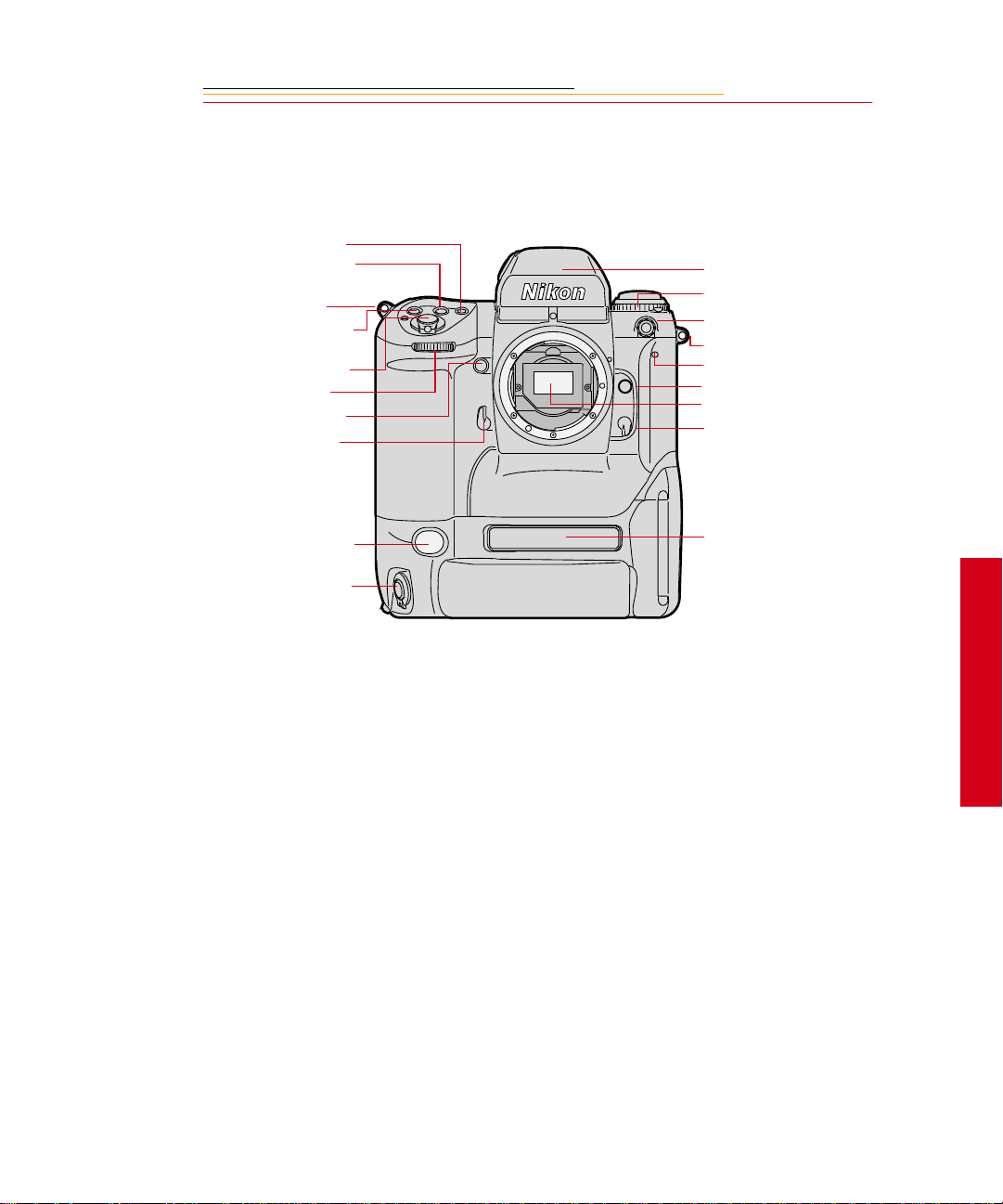
Nomenclature
Camera Front
AF Area Mode button
Exposure Mode (MODE)
button
Camera strap eyelet
Exposure Compensation
button
Shutter Release button
Sub-Command dial
Depth-of-field Preview
button
Mirror Lockup lever
Viewfinder
Drive Mode/Self-timer
selector
Sync terminal
Camera strap eyelet
Self-timer LED
Lens Release button
Anti-aliasing or IR filter
Focus Mode selector
White Balance sensor *
Vertical Shutter release
Product label
* With firmware version 3.09, or higher, white balance is accomplished using image data
rather than the White Balance sensor.
☛ An IR filter is included with the base camera kit. An anti-aliasing filter is included
with the regular kit.
2
Your Camera
2-3
Page 29
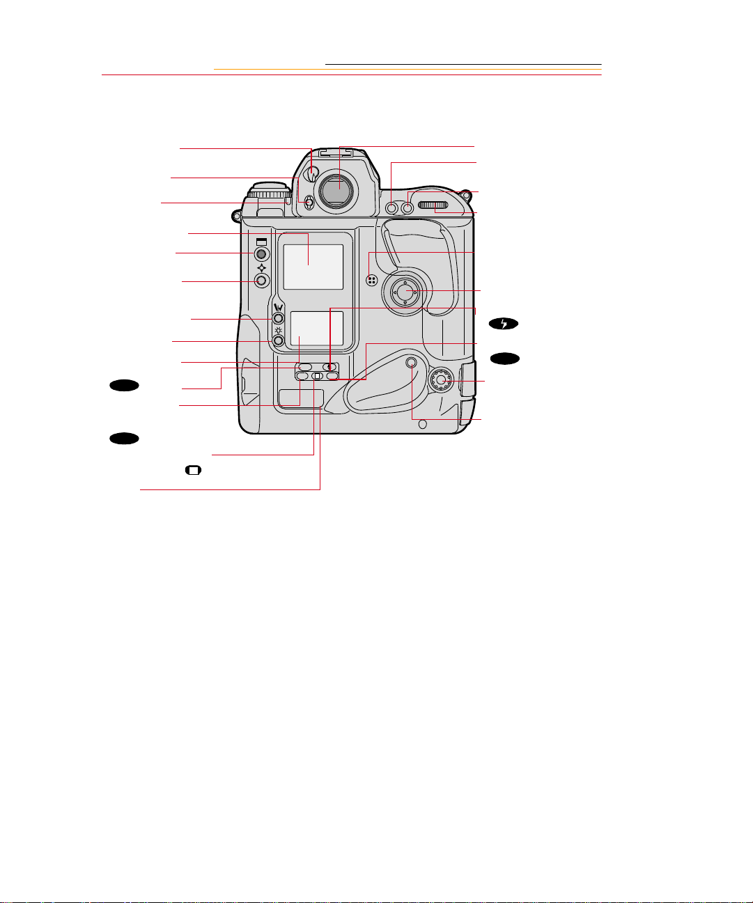
Camera Back
Eyepiece Shutter
lever
Finder Release
button
Alert LED
Image L CD p an el
Display button
Selector button
Record/Tag button
White Balance
button
Back Status LCD
panel
ISO
)button
(
Auto Exposure/
Flash Exposure
Bracketing
BKT
) button
(
Shutter Speed/Aperture/
Focus Area Lock button
Label
L
Viewfinder eyepiece
Auto Exposure/
Autofocus Lock button
AF Start (AF-ON) button
Main-Command dial
Microphone
Navigate switch
Flash Sync Mode
(
) button
Custom Setting Menu
CSM
(
ISO
L
CSMBKT
) button
Remote release port
Vertical AF Start (AF-
ON) button
2-4
Page 30
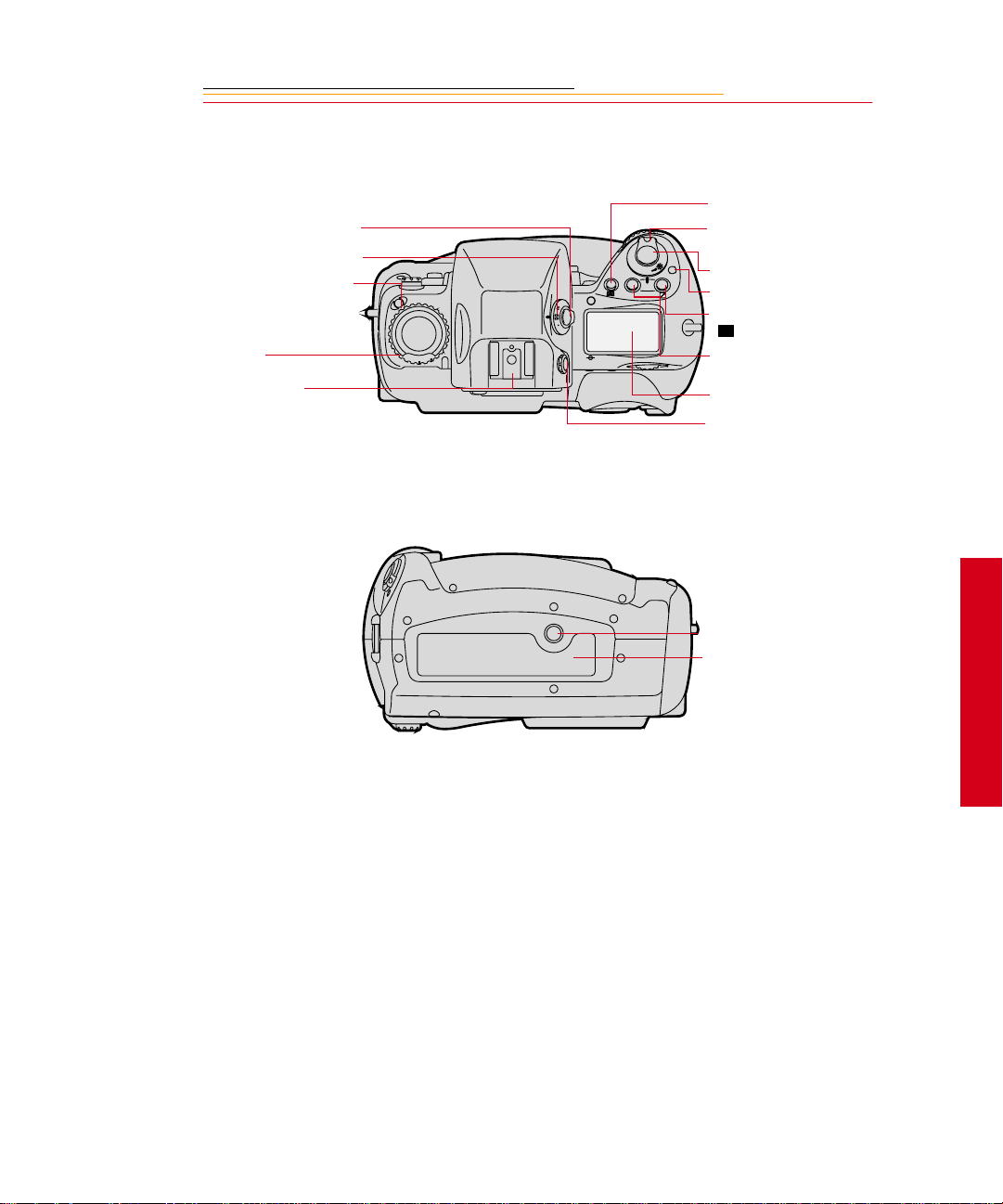
Camera Top
e
Metering System selector
lock release
Metering System selector
Drive Mode selector lock
release
Drive Mode/Self Timer
selector
Accessory Shoe
Camera Bottom
AF Area Mode button
Power/LCD Panel
O
F
F
O
N
MODE
L
C
S
Illumination swit ch
Shutter Release button
Power Switch lock releas
Exposure Compensation
+/-
button
Exposure Mode (MODE)
button
Top Status LCD panel
Diopter Adjustment knob
2
Tripod mount
Data plate label
Your Camera
2-5
Page 31

Camera Sides
Battery/PC Card door
Battery/PC Card door latch
IEEE 1394 cable port (cover not shown)
AC Adapter connection (cover not
shown)
2-6
Vertical shutter release lock
Vertical Shutter release
Camera strap eyelet
Page 32

Open Battery/PC Card Door
Battery
Card Busy LED
Serial port
PC Card
Eject button
2
Your Camera
2-7
Page 33

Viewfinder
1
5
2
3
4
6
7
8
1. Focus area indicators
2. Exposure level (for waist-level finder DW -30
or 6x high-magnification finder DW-3i in
manual exposure)
3. Reference circle for Center-weighted
metering
4. Focus brackets/Spot metering
5. Green Ready light
6. Focus indicators: • indicates a subject is in
focus; blinking indicate that autofocus is
impossible; and arrows indicate front and
rear focus respectively
7. Aperture direct readout
8. Focus area indicators
9 10 11 12
13 14 15 16 17
9. Shutter speed lock indicator
10. Aperture lock indicator
11. Exposure mode
12. Exposure compensation
13. Metering system
14. Shutter speed
15. Aperture
16. Electronic analog exposure display
17. Exposure compensation
2-8
Page 34

Navigate Sw i t ch
The Navigate switch is a four-way rocker switch located on the back of the camera. It is
accessible whether you are holding the camera horizontally or vertically.
Display button
Selector button
Navigate Switch
Record/Tag button
White Balance button
ISO
BKT CSM
L
Using the Navigate switch to Navigate the Image LCD Panel
The Navigate swit ch opera tes in the f ollowi ng manner whe n you use it with th e Displa y or
Selector buttons (described on the next page):
✔ Navigate through images displayed on the Image LCD panel by pressing and
holding the Selector button and pressing the top, bottom, right, or left side of the
switch. Refer to “Image LCD Panel” on page 2-12.
✔ Navigate up or down through vertically arranged menu options by pressing and
holding the Selector button and pressing the top or the bottom of the switch.
✔ Navigate across the menu bar or through horizontally arranged menu options by
pressing and holding the Display button and pressing the right or left side of the
switch.
Using the Navigate switch to Select the Focus Are a
When you use the Navigate switch wit hout the Display or Selecto r b utt ons, you can select
the desired focus area. Refer to “Selecting the Focus Area” on page 9-1.
☛ If you select Dynamic AF’s primary sensor or the single AF sensor, you can prevent
accidental change by using the Navigate switch with the Focus Area Lock button.
2
Your Camera
2-9
Page 35

Digital Function Buttons
There are fou r bu tt ons ass oci at ed wi t h your ca mera ’s digital fu nct io ns. You can access the
digital functions when you use these buttons in conjunction with the Navigate switch.
Display Button
✔ Press and release the button to turn the Image LCD panel On or Off.
✔ Press and h ol d t he button and use the Navigate switch to scroll across t he menu bar
icons.
Selector button
✔ Press and hold the button and use the Navigate switch to scroll through images or
menu options. Release the button to select the desired image or menu option.
✔ Press and hold the Display button and the Selector button at the same time to turn
the Image LCD panel on and display a screen where you can delete the currently
selected image.
Record/Tag Button
✔ Press and releas e t h e but t on t o ta g or untag the selected image. You can tag images
that you do not wish to delete. Refer to “Tagging Images” on page 12-10.
✔ Press and hold the but t on and speak into the microphone to record a sound file and
associate it with the current image. Refer to “Associating Sound Files With
Images” on page 12-11.
White Balance Button
✔ Select Preset White Balance then press and hold the button and use the Navigate
switch to select the desired White Balance icon on the Back Status LCD panel.
Refer to “White Balance” on page 8-1.
2-10
Page 36

LCD Panels
O
F
F
O
N
MODE
LOCK
LOCK
LOCK
+
BKT
L
C
S
+
ISO
SLOW
REAR
BKT
CUSTOM
AUTO
ISO
L
CSMBKT
Top Status LCD Panel
Shutter speed lock
Shutter speed
Auto Exposure/Flash Exposure
bracketing
Exposure mode
Flexible program
Exposure compensation
Exposure compensation value
LOCK
+
+
BKT
Top Status LCD panel
Image LCD panel
Back Status LCD panel
Aperture lock
LOCK
Aperture
LOCK
Focus area lock
Focus area/AF area mode
2
Your Camera
2-11
Page 37

Back Status LCD Panel
ISO/Bracketing information/
Custom Setting
ISO Setting mode
Bracketing bar graphs
Auto Exposure/Flash Exposure
Bracketing
White Balance
Frame number
Frames remaining on PC Card
ISO
BKT
AUTO
SLOW
REAR
CUSTOM
Flash sync mode
Personal computer
connection
Custom setting
Card present
Microphone
Battery level
Image LCD Panel
The Image LCD panel has been designed for ease of use with maximized space for menu
choices and image-related information.
Menu Bar
The Menu bar is only displayed at your request. When you turn on the Image LCD panel,
the last screen used appears without the Menu bar. If you then press the Display button,
the Menu bar appears.
☛ Shortcut: press and hold the Display button to turn on the Image LCD panel and
display the Menu bar.
When the Menu bar is displayed, the remainder of the screen is grayed-out.
2-12
Page 38

When you select a Menu bar icon, the following screens appear:
Icon Function Dropdown Menu
Folder icon Displays the Folder
dropdown menu.
Menu icon Displays a
dropdown menu
with choices for the
Main, Properties,
and Custom Settings
menus.
Display icon Displays a
dropdown menu
with choices for
Single, Four, and
Nine Image Review
mode.
One PC Card:
Tw o PC Cards:
2
Your Camera
Contrast icon Displays the Display
Contrast screen
where you can
adjust contrast
2-13
Page 39

Navigation Techniques
Use the following guidelines when navigating the Image LCD panel
To Display the Menu bar and
select a Menu bar icon:
Press and hold the Display button
and use the Navigate switch until
the desired icon is highlighted.
To Display a Dropdown menu:
Highlight the Folder, Menu, or
Display icon, and conti nue pres sin g
the Display button until the
dropdown menu appears.
2-14
Page 40

To Choose an item from a
dropdown menu:
Continue to press the Dis play button
and use the Navigate switch until
the desired menu choice is
highlighted.
To Choose an item from a menu
screen:
Press and hold the Selector button
and use the Navigate switch to
highlight your choice.
2
Your Camera
2-15
Page 41

Status Bar
A Status bar ap pears whenever image s a re di spl ayed (Single, Four, or Nine Image Rev iew
mode). Information about the currently selected image appears on the Status bar:
The currently active PC Card (if
there are two cards in the camera)
Two PC Cards
One PC Card
The currently active folder
Sound icon (if one or more sound
files are asso ciated wit h the selecte d
image)
Tag icon (if the selected image has
been tagged).
2-16
Page 42

Command Dials
Your camera’s Main-Command dial and Sub-Command dial can be used alone or in
combination with other buttons to select various functions or modes.
Main-Command Dial
Use the Main-Command dial by itself or with various buttons to perform the following:
Rotating the Main-Command Dial by Itself
✔ Select the shutter speed in
Shutter-Priority Auto or Manual
exposure mode. Refer to
“Shutter-Priority Auto Exposure
Mode” on page 13-1 or “Manual
Exposure Mode” on page 13-8.
AE-L
AF-L
AF-ON
✔ Perform the Flexi ble Progra m in
Programmed Auto exposure
mode. Refer to “Flexible
Program” on page 13-13.
2
Your Camera
2-17
Page 43

Rotating the Main-Command Dial While Pressing Buttons
✔ Select Exposure mode. Refer to
“Exposure Mode” on page 8-14.
ISO
O
F
MODE
L
✔ Perform Exposure
F
O
N
Compensation. Refer to
“Exposure Compensation” on
page 13-19.
✔ Select AF area mode. Refer to
the “Selecting AF Area Mode”
section on page 9-4.
✔ Select ISO. Refer to “ISO” on
page 10-9.
✔ Select Flash Sync m ode. Refer
to “Flash Sync Mode” on page
11-13.
✔ Select the Cus tom Settin g menu.
Refer to “Custom Settings” on
CSMBKT
page 13-32.
✔ Lock shutter speed/aperture/
focus area. Refer to “Locking
Shutter Speed” on page 13-3.
✔ Set or cancel Auto Exposure/
Flash Exposure Bracketing.
Refer to “Auto Exposure/Flash
Expos ure Bracketing” on page
13-24.
2-18
Page 44

Sub-Command-Dial
Use the Sub-Command dial by itself or with various buttons to perform the following:
Rotating the Sub-Command Dial by itself
✔ Select the aperture in Aperture-
Priority Auto or Manual
MODE
exposure mode. Refer to
“Aperture-Pr iority Auto
Exposure Mode” on page 13-4
or “Manual Exposure Mode” on
page 8-16.
☛ If you are using a non-CPU
lens (without a
microprocessor), you must set
the aperture on the lens’
aperture ring.
Rotating the Sub-Command Dial While Pressing Buttons:
✔ Set the number of e xposur es and
✔ Lock the apert ure in A mode and
ISO
L
CSMBKT
✔ Select and make a Custom
2
Your Camera
compensation value in Auto
Exposure/Flash Exposure
Bracketing. Refer to “Auto
Exposure/Flash Exposure
Bracketing” on page 13-24.
Shutter speed in S mode. Refer
to “Locking the Aperture” on
page 13-7.
Setting. Refer to “Making a
Custom Setting” on page 13-32.
2-19
Page 45

Drive Mode/Self-Timer Selector
This dual-purpose control allows you to select a Drive mode or set the self timer.
When you select a Drive mode, you speci fy whethe r one or mo re imag es wil l be cap tur ed
when you depress the Shutter Release button.
To set a Drive mode:
Press the lock release for the Drive
mode selector and rotate the Drive
mode/Self-timer selector. Set S for
Single-frame shooting, C
Continuous low- speed shoo ting, C
for Continu ous hi gh- spe ed s hooting
S for Continuous silent-low-
or C
speed shooting. Refer to “Drive
Mode” on page 10-10.
C
L
S
C
H
C
To set the Self-timer:
Press the Drive mode selector lock
release and rotate the Drive mode/
self-timer selector to the (selftimer) position. Refe r to “SelfTimer” on page 13-28.
L for
H
2-20
C
S
Page 46

Lens
Refer to Appendix C for a list of lenses that are compatible with your camera.
CAUTION:
Only use lenses that are listed in Appendix C. Other lenses can potentially break
your camera’s anti-aliasing or IR filter. Refer to “Anti-aliasing filter” on page 2-
25.
Mounting the Lens
1 Remove the camera body cap
and the front and rear lens caps.
2
Your Camera
2-21
Page 47

2 Position th e le ns i n the camera’ s
bayonet mount so that the
mounting indexes on the lens
and camera body are aligned.
Taking care not to press the lens
release button, twist the lens
counterclockwise until it locks
in place.
When mounting or removing a
lens, make sure that the
camera’s power is turned Off.
Setting the Lens to the Minimum Aperture
For Programmed Auto or Shutter-Priority Auto mode, use the minimum aperture lock
lever to lock the lens aperture at f/16.
2-22
Page 48

1 Set the lens to its minimum
aperture (f/16).
2 Slide the lock lever in the
direction of the aperture ring so
that the white dot on the tab
aligns with the orange dot.
Slide the lock lever in the
opposite direction to release the
lock.
☛ Apertur e sett ing op erations are
performed using the SubCommand dial. Do not move
the lens aperture once it is set
to its minimum aperture.
☛ The aperture can also be set
with the lens aperture ring in
Aperture-Priority Auto or
Manual Exposure mode. In
these cases the aperture can
only be verified through
aperture direct-readout.
2
Your Camera
2-23
Page 49

Removing the Lens
Press and hold the Lens Release
button and turn the lens clockwise.
☛ If you don’t plan to mount a
lens for a while, attach the
supplied BF-1A body cap.
(The BF-1 body cap canno t be
used on your camera.)
2-24
Page 50

Imager
The imager records light when you capture an image. The imager size and ISO varies,
depending on your camera model.
Camera Imager Size ISO
DCS 620 2 million pixels 200 - 1600
DCS 620x 2 million pixels 400 - 4000
DCS 660 6 million pixels 80 - 200
DCS 660M 6 million pixels 320 - 800
Anti-aliasing filter
The DCS 620, DCS 620x, and DCS 660 cameras eac h contai n an anti- aliasi ng filt er whic h
improves overall image quality and helps reduce aliasing at certain focal distances.
2
Your Camera
IR Filter
The DCS 660M and s ome DCS 6 20 cameras (base camera kit s) us e a n I R fi l ter i n pl ac e of
an anti-aliasing filter.
2-25
Page 51

Viewfinder Diopter
You can compensate for near- or far-sightedness and see more clearly through the
viewfinder by adjusting the finder diopter within a continuous range of from –3 to +1.
1 Pull the Diopter Adjustment
knob and rotate it in either
direction until the f ocused image
in the viewfinder’s reference
circle appears sharp
2 Push the knob back in to lock.
2-26
Page 52

Illumination Switch
You can illuminate the Top and Back Status LCD panels for easy viewing at night or in
low light situations.
Rotate the LCD Panel Illumination
to illum inate
O
F
MODE
switch toward the
the Top and Back Status LCD
panels.
F
O
N
The LC D pa nel illumination switch
automatically returns to the on
position, and the LCD panels
remain illuminated as long as the
meter is on. (You can change the
time that the meter remains on using
custom setting #15. Refer to
“Custom Settings” on page 13-32.)
T o turn the illu mina tion of f before it
times out, rotate the LC D Panel
Illumination switch clockwise
again.
After the shutter is released, the
LCD panel illumination
automatically turns off.
2
Your Camera
2-27
Page 53

Mirror Lockup Lever
When using super-telephoto lenses or performing photomicrography, it is necessary to
reduce camera vibration to the absolute minimum.
Lock the reflex viewing mirror in
the up position by rotating the
mirror lockup lever
counterclockwise until it stops.
☛ When the mirror is locked up,
you cannot op er ate t he camera
in any Auto Exposure or
autofocus mode, even though
the viewfinder LCD may
indicate otherwise. Any
indication of light in the LCD
is a resu lt of light entering
through the viewfinder
eyepiece.
CAUTION:
Do not to leave the camera in direct sunlight when the reflex mirror is locked in
the up position. The sunlight may damage the shutter curtain.
2-28
Page 54

Depth-of-Field Preview Button
The depth of field is the zone of acceptable focus in front of and behind the subject. You
can preview this zone using the Depth-of-Field Preview button.
The Depth-of-Field Preview button will not work properly if there is no PC Card inserted.
In Aperture-Priority Auto or
Manual Exposure mode, press the
Depth-of-field Preview button to
MODE
stop the lens down to the aperture
that was set wi th th e Sub-Co mmand
Dial.
In Programmed Auto or ShutterPriority Auto Exposur e mode, the
lens will be stopped down to the
automatically set aperture. When
you press the Depth of Field
Previ ew button, the viewed image
becomes progress ively d arker as the
aperture gets smaller. Those
portions of the image that appear in
focus when th e butto n is pre ssed ar e
within the depth of field.
2
Your Camera
Be aware of the following when
using the Depth of Field Preview
button:
✔ When using lenses with a meter
coupler, it is not possible to
attain correct exposure because
exposure must be det ermined by
full-a perture metering.
✔ Do not use the Spot Metering
system when using the Depthof-Field Preview button.
✔ During preview, the aperture
cannot be adjusted and
autofocus is not possible.
2-29
Page 55

Accessory Shoe
L
C
S
Sync Terminal
MODE
Located at the top of the MultiMeter Finder, the ISO-type hot s hoe
allows direct mounting of a wide
range of Nikon-de dicat ed ele ctronic
O
F
F
O
N
Speedlights. Refer to “At taching the
SB-28D or SB-28DX” on page 11-
3.
CAUTION:
Do not use speedlights from
other manufacturers since
higher voltages and/or extra
hot shoe contacts can damage
your camera.
2-30
Your camera features a separate
sync termi nal that acce pts all flashe s
with standard PC-t ype, plug -in sync
cords.
CAUTION:
Flashes with excessive trigger
circuit voltage can damage
your camera. Consult your
service representative for
questions on compatible
flashes.
Page 56

Self-Diagnostic Shutter System
Y ou r camer a is equi pped with a selfdiagnostic shutter that automatically
controls the shutter speed for each
release of the shutter.
The self-diagnostic shutter
automatically det ect s ina ccur acies
in performance and readjusts the
shutter speed accuracy for
subsequent image capture.
If a malfunction occurs or the
shutte r curtain fails to operate, the
alert LED blinks and
the Top Status LCD panel and
viewfinder. Turn the camera power
Off, then On. Refer to “Turning the
Camera On and Off” on page 3-1. I f
the blinking stops, the malfunction
is correcte d. If the al ert LED a nd
resume blinking, turn the power off
and take the camera to your service
representative.
Err blinks in
Err
2
Your Camera
2-31
Page 57

Changing Viewfinders
A modified DP-30 viewfinder is included with the DCS 620 and 620x cameras. (A
standard DP-30 viewfinder is included with the DCS 660 and 660M cameras.) See
Appendix C for a list of compatible viewfinders. Using other viewfinders with your
camera can decrease the “active area” of the viewfinder.
Removing the Finder
Turn the camera off. Refer to
1
“Turning the Camera On and
Off” on page 3-1.
2 Press and hold the Finder
Release button.
☛ This but to n i s metallic gray on
the DCS 620 and 620x
cameras and bla ck on the DCS
660 and 660M cameras.
3 Slide the viewfinder away from
the lens.
2-32
Page 58

Attaching the Finde r
Slide the finder in until it clicks in
place.
4 Be sure that the Finder Release
button has returned to its
original position.
IMPORTANT:
Be sure the viewfinder is
attached when y ou are ca pturing
images. If t he shutter is released
without a viewfinder attached,
stray light may enter thr oug h the
focusing screen.
When removing a viewfinder, be
careful not to leave smudges or
fingerprints. Place the detached
viewfinder on a soft, clean cloth.
2-33
2
Your Camera
Page 59

Changing Focusing Screens
1 Turn off the camera and remove
the finder. Refer to “Removing
the Finder” on page 2-32.
2 Insert your fingernail under the
rear edge of the focusing screen
and lift the screen out.
3 To install a focusing screen,
insert the front edge under the
central ridge, then push the rear
edge down into place.
IMPORTANT:
When removing a focusing
screen, be careful not to leave
smudges or fingerprints. Place
the detached screen on a soft,
clean cloth.
2-34
Page 60

Camera Straps
A neck strap and a hand strap are included with your camera. You can attach either or
both.
Attaching the Neck Strap
Thread the ends of the neck strap
through the strap fixtures. Pull
firmly on the stra p to make su re it is
held securely by the buckles.
2
Your Camera
2-35
Page 61

Attaching the Hand Strap
1
Thread the strap through both
loops in the hand strap pad.
2 Place the three-holed buckle on
the strap and thread through the
camera’s top strap fixture.
3 Thread the oth er end of the str ap
through the camera’s bottom
strap fixture.
4 Thread the top strap back
through the buckle as shown.
5 Thread both ends of the strap
back through the loops on the
hand strap pad.
6 Place the two-holed buckle on
the top strap.
2-36
7 Tuck the top strap through the
bottom loop in the hand strap
pad.
8 Thread the bot tom s tr ap th rough
the two-holed buckle as shown.
9 Tuck the bottom strap through
the top loop in the hand strap
pad.
Page 62

Name Plate
Using the DCS Acquire Module or DCS TWAIN Data Source, you can enter text that
appears in certain screens on your camera. The Name Plate is useful for personalizing
your camera, for example, “This camera belongs to Joe Smith”.
In the DCS Acquire Module or DCS TWAIN Data Source:
1 Click the Camera Control button.
The Camera Control dialog box appears.
2 Click the Properties button.
The Properties dialog box appears.
3 Scroll through the list and select the Name Plate property.
4 Enter up to 50 characters of text in the Name Plate text box.
The text appears in the following screens on the camera’s Image LCD panel:
✔ No images in folder
✔ No images in memory
✔ No card in camera
2
Your Camera
2-37
Page 63

INSERT
PHOTO
HERE
Powering Your Camera
3
Operate your ca mera usi ng eith er batt ery or AC power. You can pr eserv e bat tery po wer by
using the AC adapter whenever possible.
You can charge your camera batteries using a battery charger and an international power
cord set. These items are included with most cameras (except base camera kit). They are
also available from Kodak as accessories. The power cords allow you to use the AC
adapter and the battery charger in Australia, Great Britain, Germany, Japan, and the
United States.
Turni ng th e Ca me ra On a nd Off
O
F
MODE
1 Press and hold the Powe r Switch
Lock release.
F
O
N
2 While continuing to press the
Power Switch Lock release,
rotate the Power switch
clockwise to turn the camera On
and counter-clockwise to turn
the camera Off.
3
Power
3-1
Page 64

Batteries
Your camera can use either NiMH (nickel metal hydride) or NiCd batteries. Extended
camera metering, autofocus, or extensive LCD panel operation reduces the number of
images available from a full battery charge.
With a fully charged battery, the camera can provide up to the following number of
images:
Camera NiMH battery NiCd battery
DCS 620 and 620x 1000 300
DCS 660 and 660M 300 100
☛ Battery performance deteriorates in temperatures below 32°F (0°C). Keep the
camera and a spare battery close to your body or in an inside pocket to keep it warm
until use.
WARNING:
Batteries can explode or cause burns if disassembled, shorted, exposed to high
temperatures, or disposed of in fire. Be sure to observe all precautions indicated on
the battery package. Always keep batteries out of the reach of children and return
them to your camera dealer for recycling when you are finished with them.
CAUTION:
If you don’t plan to use your camera for five or more days, remove the battery
from the camera and carrier. This will prevent battery discharge, and/or damage
due to battery leakage.
3-2
Page 65

Inserting/Removing Batteries
You must charge a battery before using it for the first time.
☛
ISO
BKT
AUTO
SLOW
REAR
CUSTOM
1 Check that the Card Pr esent ic on
on the Back S tatus LCD panel i s
not blinking.
IMPORTANT:
If the Card Present icon or the
Card Busy LED inside the
Battery/PC Card door are
blinking, wait until the blinking
stops before continuing. (You
can lose data if you remove the
battery while the card is busy.)
Turn off the camera before
changing batteries, otherwise
the camera can “lock up” and
stop you from doing anything. If
this happens, turn off the
camera, r emov e the new batt ery,
wait 10 seconds, insert the new
battery, then turn on the camera.
2 Turn off the camera.
3
Power
3-3
Page 66

3 Lift the latch assembly on the
Battery/PC Card door and turn it
counter-clockwise to open the
door.
IMPORTANT:
Be sure that the Card Busy LED
is Off before you continue.
3-4
Page 67

The white arrow opposite the
connector should be pointing
upwards as the battery is
inserted.
Some (not all) cameras have a
white arrow pointing
downwards (towards t he camer a
bottom) just above the battery
compartment. If your battery
and your camera both have the
arrows, then the arrows should
be aligned as you insert the
battery into the camera.
4 T o insert: slide the bat tery to the
back of the batt ery slot and press
firmly in place.
To remove: slide the battery out
of the battery slot.
5 Close the Battery/PC Card door.
6 Turn the latch assembly
clockwise and r et ur n it to its flat
position.
☛ You can insert or remove a
battery while the camera is
connected to an AC adapter
for camera. Refer to “AC
Adapter for Camera” on page
3-13.
3
Power
3-5
Page 68

Checking Battery Status
You can determine whether a battery needs charging by viewing the Battery icon on your
camera’s Back Status LCD panel. (If the camera is using an AC adapter, the Battery icon
is not displayed.)
1 Insert a bat tery if there is not one
in the camera. Refer to
“Inserting/Removing Batteries”
on page 3-3.
2 Turn on the camera.
ISO
BKT
AUTO
SLOW
REAR
CUSTOM
3 Check the Battery icon on the
Back Status LCD pa nel.
The icon indicates whether the
battery needs changing.
Full
☛ If the icon indicates that the
Low
battery is empty, the camera
will not capture images.
Insufficient
Empty
Always check the battery status at the following times:
✔ When loading a new battery
✔ After lengthy storage
✔ If the shutter will not release
✔ In cold weather
✔ Before an important assignment
3-6
Page 69

Battery Charger
You need to charge a battery be fore us ing it for the fir st ti me and whenev er it i s low. If you
plan to us e your c amera wi thout the AC ad apter for a n exten ded period of ti me, it is a go od
idea to charge one or more batteries before you begin. An external battery charger is
included with your camera.
For the best results, store and use the battery charger within the following temperature
ranges:
Storage temperature range: -25°C to 70°C (-77°F to 158°F)
Charging temperature range: 0°C to 45°C (32°F to 113°F)
The battery charger has two slots. A yellow and a green light near the slots illuminate to
indicate the status of the batteries:
Yellow light Green light Battery Status
Off
On
Off
Slow Flashing
Fast Flashing
* While you can use a battery when the light turns green, you will have optimal results if
you leave the battery in the charger for 2 hours after the light turns green.
Off
Off
On *
Off
Off
No battery inserted
Charging
Fully charged
Conditioning (Discharging)
Error
3-7
3
Power
Page 70

Charging Batter i es
1
Remove the battery from the
camera (page 3-3).
2 Plug the cable from the AC
adapter for charger into the
battery charger jack.
3 Select the international power
cord that is appropriate for your
area.
4 Insert the appropriate end of the
international power cord into the
receptacle on the rear of the AC
adapter for charger.
3-8
5 Plug the power cord into a wall
outlet.
Page 71

ISO
BKT
AUTO
SLOW
REAR
CUSTOM
6 Insert one or two batteries in the
slots in the battery charger.
☛ If you are charging one
battery, you can use either slot .
On average, a battery is charged
in approximately one hour. If
two batteries are inserted, they
are charged simultaneously.
7 Once the green light turns on,
wait four hours, the n remove the
battery or batteries from the
charger.
If you don’t wait two hours,
batteries will only be charged to
80% of capacity.
8 Insert a charged battery into the
camera.
9 Close the camera door.
The Battery icon is displ ayed on
the Ba ck Status LCD panel
when a battery is in the camera,
the camera is turned on, and the
camera is not in PowerSave
mode (page 3-11).
☛ The Battery icon is not
displayed if the AC ada pter is
connected.
If your battery charger does not function as expected, check the following:
✔ The wall adapter is properly connected.
✔ There are no foreign objects lodged in the pockets.
✔ The batteries are inserted so that they properly mate with the connector in the
bottom of the pocket.
☛ No har m wil l c ome t o your batteries if you le ave them in the charger for an extended
period of time.
3-9
3
Power
Page 72

Conditioning (Discharging Batteries)
You may occasionally need to condition a battery. You would only do so if a battery
provides a noticeably shorter run time (less than 50% of normal capacity).
IMPORTANT:
Don’t condition your batteries too often or they will wear out prematurely.
1 Insert one or two batteries into
the slots on t he to p of the b attery
charger.
2 Press the Condition buttons
associate d wit h the ba tt eries that
you wish to condition.
The batteries will first be
conditioned, then charged. The
whole process can take up to
5 1/2 hours.
3 Remove the batteries from the
battery charger four hours after
the gre en light turns on.
☛ You can condition a battery in one slot while charging a battery in the other.
3-10
Page 73

Battery Conservation
Your camera has several built-in functions that minimize drain on your battery.
PowerSave Mode
If your camera is powered by an AC adapter or is connected to a computer with
☛
IEEE 1394 cable, it will not enter PowerSave mode.
If you don’t use your camera for 30 minutes, it will enter PowerSave mode (go to sleep).
In PowerSave mod e, the f lash will no t be kep t ch ar ged and t he bac klight for t he Top Status
and Back Status LCD panels will turn off.
☛ You can change the setting f o r Power Save time. Refer to “Setti ng Pow er Save Time”
on page 4-3.
Waking your Camera from PowerSave Mode
Lightly press the Shutter Release
button.
O
F
F
O
N
MODE
3-11
3
Power
Page 74

Image LCD Panel Timeout
The Image LCD panel will turn off if you have not used the camera for 60 seconds.
☛ You can change the setting for Image LCD timeout. Refer to “Setting Display Off
Time” on page 4-3.
Press the Display button to turn the
Image LCD panel On again.
Meter Timeout
Your camera’s meter remains on for 8 seconds after you lightly press the Shutter Release
button.
☛ You can change the setting for meter timeout. Refer to “Making a Custom Setting”
on page 13-32.
When the meter times out, the following turn off:
✔ Viewfinder LCD
✔ Top Status LCD panel
Situations Us in g Ex tra Battery Power
✔ Use of a telephoto or wide angle fisheye lens and constant auto-focusing
✔ Frequent use of the Image LCD panel
✔ Cold temperatures
✔ Turning the camera on and off frequently
3-12
Page 75

AC Adapter for Camera
Use an AC adapte r when ever poss ible to lesse n dra in on the batter y. You sh ould al so use it
when your camera is connected to a computer to prevent loss of power if the battery
should lose its charge.
CAUTION:
Operate the equipment only from the type of power source indicated on the AC
adapter. A line voltage outside of this range can destroy the AC adapter and/or
the ca mera.
Tips
✔ Use only the KODAK AC adapter; do not plug other chargers or adapters into the
camera.
✔ The AC adapter is for indoor use only.
✔ Do not use the AC adapter for any purpose other than for the camera.
✔ The AC adapter does not have an On/Off switch. To turn off the AC adapter, you
will need to unplug it
3
Power
3-13
Page 76

Connecting the AC Adapter for Camera
1
Open the connector cover at the
side of the camera.
2 Plug the AC adapter for camera
into the AC Adapter connection.
3 Select the international power
cord that is appropriate for your
area.
3-14
Page 77

4 Plug the appropriate end of the
power cord into the AC adapter
for camera.
5 Plug the power cord into a wall
outlet.
☛ You can connect or di sc onne ct
the AC adapter while a battery
is in the camera.
☛ The AC adapter for camera
NOT charge a battery in
will
the camera.
3-15
3
Power
Page 78

INSERT
PHOTO
HERE
Configuring Your Camera
4
This section describes how to change various camera settings.
Date and Time
You can set the date and time. The format for the date is year/month/day, and the format
for time is hour:minute:second based on a twenty-four-hour clock.
The setting is maintained when you turn off the camera, after PowerSave, or when you
remove the battery for a few days.
☛ There is a small rechargeable battery in the camera which can lose its charge if you
remove the main bat te ry f or a lo ng period of time. When you insert the main battery,
the small battery is recharged, but you will need to reset the date and time.
4
Configuring
1 Select the Menu icon, then
choose Main Menu from the
dropdown menu. Refer to
“Navigation Techniques” on
page 2-14.
2 Select Date/Time from the Main
menu.
4-1
Page 79

The Date/Time screen appears.
There ar e si x fields : year, month,
day , an d ho ur, minutes, sec onds .
3 Press and hold the Selector
button and press the left or right
side of the Navigate switch to
highlight the desired field.
4 Press and hold the Selector
button and press the top or
bottom of the N avigate switch to
change the highlighted field.
☛ When you hold the Selector
button to highlight the
Seconds field, the seconds
stop counting and you can
reset the field. The counting
resumes when you release the
button.
4-2
Page 80

Camera Prop erties
4
You can set the following camera properties using camera controls: Display Off time,
Powersave time, Resolution, Enable Sharpening, Use FOLDER01,and Total Actuations.
☛ The list of properties may change as new versions of firmware become available.
The wording in the screens may not be exactly as shown.
Setting Display Off Time
You can change the Display Off time (the length of time before the Image LCD panel
turns off). Extended use of the Image LCD panel can drain your battery.
The Display Off Time screen (and the PowerSave screen) operate a little differently than
the others.
1 Select the Menu icon, t hen
choose Properties from the
dropdown menu. Refer to
“Navigation Techniques” on
page 2-14.
2 Select Display Off Time from
the Properties menu.
The Display Off Time screen
appears.
Configuring
3 Press and hold the Display
button and press the left or right
side of the Navigate switch to
highlight the desir ed number.
4 Press and hold the Display
button and press the top or
bottom of the Navigate switch to
change a number.
Setting PowerSave Time
Change the PowerSave time using a procedure similar to that described for changing
Display Off time.
4-3
Page 81

Enabling Sharpening
DCS 620, 620x, and 660 cameras are equipped with an antialiasing filter, an optical filter
that is mounted inside the camera in front of the electronic imager. This filter eliminates
unwanted color art ifact s, and imp roves o veral l ima ge qual ity at the expe nse of a smal l loss
of sharpness. Depending on your subject, you may or may not want to allow sharpening
when the image is processed. For example, you might wa nt to sharpen an im ag e of a piece
of equipment, and might not want to sharpen a portrait or an image of clothing items.
☛ The DCS 660M and some DCS 620 cameras (base camera kit) use IR filters instead
of antialiasing filters.
Sharpening can be applied in one of two places:
✔ In the DCS Host software during image processing.
✔ On the camera when you process an image. Refer to “Changing Processing
Settings” on page 6-5.
This section describes your camera’s Sharpening property which determines whether
sharpening is applied by the DCS Host software’s “At Capture” setting in the Sharpen
Image preference. (If you set the Sharpen Images preference to “On” (or “Off”), images
are sharpened (or not), regardless of the camera property setting. Refer to the DCS Host
Software User’s manual.
☛ The Sharpening property has no impact on whether sharpening is applied during
processing in the camera.
The default Sharpen ing property setting is Yes for DCS 660 cameras and No fo r DCS 620
and 620x cameras. (The property is not available for on DCS 660M cameras.) If you
remove the antialiasing filter, you need to set the Sharpening property to “Off”. Refer to
“Anti-aliasing Filter and IR Filter” on page 16-3.
1 Select the Menu icon, then
choose Properties from the
dropdown menu. Refer to
“Navigation Techniques” on
page 2-14.
2 Select Sharpening from the
Properties menu.
The Sharpening screen appears.
3 Choose No or Yes.
4-4
Page 82

Setting File Reso lu tion
4
You can specify a file resolution to be saved in the header of subsequently captured
images. This property does not affect image processing in the camera, the DCS Acquire
Module, or the DCS TWAIN Data Source. The spe cified r esolu tion i s used b y appli cations
such as Photoshop when displaying the images.
1 Select the Menu icon, t hen
choose Properties from the
dropdown menu. Refer to
“Navigation Techniques” on
page 2-14.
2 Select Resolution from the
Properties menu.
The Image Resolution screen
appears.
3 Select Resolution or Un its.
If you select Resolution, the
Resolution screen appears.
4 Press and hold the Selector
button and press the left or right
side of the Navigate switch to
highlight the desir ed fi el d.
5 Press and hold the Selector
button and press the top or
bottom of the Navigate switch to
change the highlighted field.
Configuring
If you select Units, the
Resolution Unit s screen
appears.
6 Select Pixels/inch or Pixels/cm.
4-5
Page 83

Determining Total Actuations
You can determine the number of images captured by your camera from the time of its
manufacture.
1 Select the Menu icon, then
choose Properties from the
dropdown menu. Refer to
“Navigation Techniques” on
page 2-14.
2 Select Total Actuations from the
Properties menu.
The Total Actuations screen
appears, informing you of the
number of images captured.
Use Folder 1
You can specify whether the default place to store images is an empty folder or folder 1
when you insert a new PC Card.
1 With the Properties menu
displayed, select Use
FOLDER01.
This Use Folder 1 screen
appears.
2 Highlight Yes or No.
If you select Yes, every time you
replace your PC Card, images
will be stored in folder 1.
If you select No, every time you
replace your PC Card, images
will be stored in the first empty
folder found on the PC Card.
4-6
Page 84

Custom Settings
4
You can set Custom Settings using the Custom Settings menu (described below) or the
CSM
button (page 4-7). In general, the method described below is easier to use, since
the settings are labeled.
1 Select the Menu icon, t hen
choose Custom Settings from
the dropdown menu. Refer to
“Navigation Techniques” on
page 2-14.
2 Select the desired Custom
Setting.
The sel ected Custom Setting
screen appears.
3 Select the desired setting.
Configuring
4-7
Page 85

INSERT
PHOTO
HERE
5
As you capture images, they are stored on a PC Card (PCMCIA card). Before capturing
images, you may want to make a few preparations so that the images will be stored
according to your needs. This chapter describes the use of the PC Card and provides
instructions for storing images.
Using a PC Card
PC Cards
5
Your camera accepts Type I, Type II, or Type III PC Cards which are compatible with the
PCMCIA-ATA interface standard. Most hard disk drive and flash memory cards may be
used. Hard disk drive cards will hold more images and are usually faster than flash
memory cards, but flash memory cards are more rugged.
☛ PC Cards must be ATA-compatible.
CAUTIONS:
Use extreme care when handling PC Cards, as they are easily damaged. If
dropped, a PC Card may be destroyed, resul ti ng i n th e l oss of all data on the car d.
PC Card
Do not remove a PC Card from the camera while the Card Present icon on the
Back St atus LCD panel or the Card Bus y LED inside the Battery/PC Car d door is
blinking. The blinking indicates that data is being read from or written to the PC
Card. You may lose data if you remove a card at this time.
5-1
Page 86

Dual Slots for PC Cards
Your camera has t wo PC Card sl ot s. With Type II PC Cards , you can use one or b oth sl ot s.
With Type III PC Cards, only one slot can be used. The card in the slot closest to the
camera back is ref erre d to as CARD0, and the card in t he slot closes t to the ca mera fro nt is
referred to as CARD1.
CARD0
CARD1
With one card, you can insert a PC Card in either slot. With two cards, the first card
inserted will be the active card. When you capture or delete images, they will be saved to
or deleted from the active card.
IMPORTANT:
Your camera uses 3 volt or 5 volt PC Cards. When you use two cards, they must both
have the same voltage rating. If you insert two cards with different voltages, neither is
powere d. A “Car d Voltage Mix” mess age appe ars. You need to re move one of the cards
so that the other can be powered.
5-2
Page 87

Inserting/Removing PC Cards
It is not necessary to turn off the camera before inserting or removing a card.
ISO
BKT
AUTO
SLOW
REAR
CUSTOM
1 Check the Card Present icon on
the Back Status LCD panel. It
blinks when a card is busy.
IMPORTANT:
If the Card Present icon is
blinking, wait until it stops
befor e con ti nui ng. ( You can lose
data if you remove the PC Card
while it is busy.)
2 Lift the latch assembly on the
Battery/PC Card door and tu rn it
counter-clockwise to open the
door.
5
PC Card
5-3
Page 88

IMPORTANT:
Be sure that the Card Busy LED
is Off before continuing.
3 To insert a PC Card: slide it all
of the way into the card slot and
press firmly.
☛ A label inside the door
indicates the proper position
for the card.
5-4
Page 89

4 To remove a PC Card, press the
Eject button and pull the card
out.
5 Close the Battery/PC Card door.
5
PC Card
ISO
BKT
AUTO
SLOW
REAR
CUSTOM
The Card Present icon is
displayed on the Back Status
LCD panel when there is a PC
Card in the camera.
5-5
Page 90

Formatting a PC Card
To prevent formatting the wrong PC Card, there can only be one card in the camera when
you format a card. Format the card using either the quick format or the full format feature.
IMPORTANT:
Quick format, while faster, is not recommended if there is a possibility that there are
defects on the PC Card.
The Recover f uncti on onl y works if a PC Car d h as been f ormatte d o n the camera. Re fe r
to “Recovering Deleted Images” on page 12-15. (If you format a card using the DCS
Host Software, the Recover function will not work.)
1 Select the Menu icon, then
choose Main Menu from the
dropdown menu. Refer to
“Navigation Techniques” on
page 2-14.
2 Select Card from the Main
menu.
The Card menu appears.
5-6
3 Choose Quick Format or Full
Format.
If two cards are in the camera,
you are prompted to remove the
inactive card. For example, if
CARD0 is active, you are
prompted to remove CARD1.
4 Remove the inactive c ard, then
select Retry.
Page 91

If you remove the active card,
the message at the left appears.
5 Re-insert the card in the proper
slot, then select Retry.
A confirmation screen appears.
6 Select Yes or No.
If you choose No, the Main
menu appears and the card is not
formatted.
If you choose Yes, the card is
formatted. A Progress screen
appears.
If you wait for the progress bar
to go to completion, a full
format occurs. If you press the
Cancel button, a quick format
occurs. With a quick format, th e
card will be usable, but
occasional errors may occur
when you save images.
5
PC Card
5-7
Page 92

Selecting a PC Card or Folder
Images are stored in folders on a PC Card. There is always at least one empty folder on
your PC Card. When you store an image in an empty folder, a new empty folder is
automatically create d. The new folder is called FolderX, (X being the next number
available).
1 Select the Folder icon. Refer to
“Navigation Techniques” on
x
page 2-14.
If there is no PC card in the
camera, an X appears within the
Folder icon. Selecting the icon
produces a menu stating No
Card.
With one PC Card inserted, this
dropdown menu appear s with a •
displayed next to the currently
active folder.
With tw o PC Cards inserte d, this
dropdown menu appears with •
displayed next to the currently
active card and folder.
A 0 or 1 appears in the Folder
icon, indicati ng the active card.
The listed folders are on the
active card. The folder list
changes when you change cards.
The numbers in par entheses next
to the cards and folders indicate
the number of images in each.
2 With two PC C ards inserted,
select CARD0 or CARD1, then
select a folder. With one card
inserted, select a folder.
5
PC Card
5-8
Page 93

Saving Files
6
JPEG and TIFF File Processing
The DCS 620 and 620x cameras support background image processing that produces
JPEG or TIFF RGB files that can be opened directly by any image editing software. This
feature is not available on the DCS 660 or 660M cameras.
The choices for processed files are JPEG Good, Better, Best, and TIFF RGB. JPEG Good
files have the most compression, JPEG Best have the least. The less compression, the
better the quality of the processed file and the larger the file size. The file size varies,
depending on content. TIFF RGB files are not compressed.
When you capture images, they are written to the selected folder using the TIFF Custom
format, regardless of whether processing is turned on. If you turn on processing, JPEG
Best, Better, Good, or TIFF RGB files are created and saved when the camera is not busy
with other tasks such as capturing images.
JPEG files are saved to a JPEG folder and TIFF RGB files are saved to a TIFF folder.
These folders are created on the PC Card when you turn processing on (if they don’t
already exist ). If y ou se lect the JPEG or TIFF fol der to rev iew image s, th en you ca pture an
image, a mess age informs you that image s cannot be saved ther e. The images are saved i n
the default f older established i n Pr oper ti es . You can specify whet her the original TIFF f il e
is saved or deleted once the JPEG or TIFF RGB file is saved.
6
Saving Files
Processing is t urn ed of f by defau lt. Whe n you turn on process ing, it stays on until you turn
it off, or remove the PC Card.
Processing with Two PC Cards
When you have PC Cards in both slots, images are processed on the card that is active
when you turn on processing. If you make the other card active, processing continues on
the inactiv e ca rd . For example, if CARD0 is active when you t urn on processing, the n yo u
change to CARD1, processing continues on CARD0, but not on CARD1. In this case, if
you want to switch processing to CARD1, you must turn off processing, then turn it back
on. When turned on, processing will automatically be set for the active card (CARD1).
6-1
Page 94

Processing Images
1
Select the Menu icon, then
choose Main Menu from the
dropdown menu. Refer to
“Navigation Techniques” on
page 2-14.
2 Select Processi ng from the Main
menu.
The Pr ocessing menu appe ars. If
two PC Cards are inserted, the
active card is indicated (for
example, All on CARD1).
3 Select your choice.
Choice Images Processed
OFF Turns off Processing
Tagged
in folder
All in
Folder
Tagged
Images
All on
Card
Change
Settings
All tagged images in
the selected folder on
the acti ve card
All images in the
selected folder on the
active card
All tagged images on
the acti ve card
All images on the
active card
Displays a screen
where you can change
Processing setti ngs
(page 6-5)
6-2
The Processing confirmation
screen appears.
4 Select OK to begin processing
or Cancel to return to the Main
menu without processing.
Page 95

When you enable processing, certain conditions may exist which will cause other screens
to appear, as shown in the table below.
Condition Screen Your Action
There is no PC Card in the
camera.
Processing is enab le d for the
selected folder and there are no
images in the folder.
Similar screens appear when the
same condition exists for tagged
images or for all images on the
card.
Processing is enab le d for the
selected folder and all images in
the folder have been processed.
Similar screens appear when the
same condition exists for tagged
images or for all images on the
card.
There are two PC Cards in the
camera. With processing enabled
for one card, you make the other
card active, then access the
Processing menu.
Click OK and insert a
PC Card.
If you click OK, new
images are processed
when you capture them
to that folder.
If processing is enabled
for tagged images or all
images on the card, then
images are processed as
you tag or capture them.
If you click Cancel,
processing is not started.
If you click OK,
processing conti nues on
the inactive car d.
If you click Cancel,
processing stops on the
inactive card. You can
then enable processing
on the active card, if
desired, if desired.
6
Saving Files
6-3
Page 96

Condition Screen Your Action
Your processing settings are set to
delete the original TIFF image
when you process files. Refer to
“Changing Processing Settings”
on page 6-5.
The active PC Card becomes full
as images are being processed.
This can occur regard les s of
whether there are one or two cards
in the camera.
You remove a PC Card while
processing is enabled (whether or
not images are currently being
processed).
If you click OK, a
second confirmation
screen appears.
If you click Cancel,
processing is not s tarte d.
The Processing menu
appears.
Click OK and delete
some images or insert a
different card.
6-4
Page 97

Changing Processin g Set ti ngs
There are several processing settings that you can change. The settings are applied to
images as they are processed.
1 Select Change Settings from the
Processing menu.
The Processing Settings menu
appears with the current values
shown in parentheses.
2 Select the desired setting.
The following screens appear,
depending on your choice:
Processing
Settings
Original TIFF Save
File Type JPEG Best
Resolution 100%
Screen
Defaults
Underlined
Delete Deletes the TIFF
Good, TIFF RGB
67% The size and spatial
50% The size and spatial
, Better,
Result
Saves the TIFF image
(default).
image after the
processed JPEG file
has been saved.
Files are processed to
the selected JPEG
quality.
Maintains t he size and
spatial resolution of
the original imag e.
resolutio n a re reduced
to two-thirds.
resolutio n a re reduced
to one-half.
6
Saving Files
6-5
Page 98

Processing
Settings
Screen
Defaults
Underlined
Result
Noise
Reduction
Look Portra it Applies a lower
Sharpening
Level *
Exposure Yes Automatic exposure
Yes
No Noise is not reduced.
Product
None
High Progressively less
Medium
Low
No Automatic exposure
Noise is reduced in
processed images.
contrast tone scale
with more deta il in t he
highlights and
shadows.
Applies a higher
contrast, more vibrant
tone scale.
No sharpening is
applied to th e finis hed
image.
sharpening is appli ed
to the finished image.
compensation is
applied
compensation is not
applied
* The Sharpening Level setting in the Processing menu determines whether sharpening is
applied when images are processed on the camera. The Sharpening property in the
Properties menu determines whether sharpening is applied by the DCS Host software.
Refer to “Enabling Sharpening” on page 4-4.
6-6
Page 99

Working with TIFF Custom Files on your Computer
If you don’ t pro cess i mages on your camera , you nee d to us e one of the f ollo wing softwa re
applications to work with the TIFF Custom files. (The TIFF Custom file format is
proprietary to Kodak.)
File Format Module
✔ This software appl ic ati on all ows yo u to op en hi gh re sol ut io n TIFF Custom images
directly into Photoshop.
DCS Acquire Module or DCS TWAIN Data Source
✔ These are full-featured image editing and acquire software applications.
If the DCS Host Software CD (included with your camera) includes the DCS Acquire
Module and DCS TWAIN Data Source version 5.8 or later , you wi ll be given th e option of
installing the DCS File Format Module. If the CD i ncl udes a ver si on pr ior to 5.8, the DCS
File Format Module is not included. To download the DCS File Format Module, visit the
Kodak Web site (www.Kodak.com).
☛ If you attempt to open TIFF Custom files in Photoshop without using the DCS File
Format Module, the DCS Acquire Module, or DCS TWAIN Data Source, only the
thumbnail version is available, yielding a less than optimal image resolution.
6
Saving Files
6-7
Page 100

IPTC Data Management
This feature allows inclusion of International Press Telecommunication Council (IPTC)
data as part of the image he ader. You en ter the IPTC data on you r computer using the DCS
Acquire Module or DCS TWAIN Data Source (version 5.8 or later) and save it to a PC
Card. (Refer to the KODAK PROFESSIONAL DCS Host Software User’s Ma nual.)
Once IPTC data has been saved to a PC Card, you can load the data into your camera
(page 6-9).
1 Select the Menu icon, then
choose IPTC Data from the
dropdown menu. Refer to
“Navigation Techniques” on
page 2-14.
2 Select your choice from the
IPTC Data menu:
None—No IPTC data will be
written to the image headers.
IPTC Data File—If there is an
IPTC file on the camera, it is
displayed. Choosing this option
writes the IPTC data to the
image header.
Load from Card—You can
load an IPTC file from a PC
Card. Refer to “Loading IPTC
Data from a PC Card” on page
6-9.
6-8
 Loading...