

Page 1

User’s Guide
for DCS 500 Series Digital Cameras
DCS 500 Series Digital Cameras
Page 2

© Eastman Kodak Company and Canon Inc., 2000 All rights reserved
Kodak and Kodak Professional are trademarks of Eastman Kodak Company
“CANON® and EOS® are registered trademarks of Canon Inc.”
Adobe, Photoshop, and Acrobat are trademarks of Adobe Systems Inc.
PN: 6b5236
Page 3

CAREFULLY READ THE FOLLOWING WARRANTY TERMS AND CONDITIONS
BEFORE USING YOUR CAMERA. USE OF YOUR CAMERA INDICATES YOUR
ACCEPTANCE OF THESE TERMS AND CONDITIONS. IF YOU DO NOT AGREE
WITH THEM, PROMPTLY RETURN THE CAMERA, UNUSED, ALONG WITH THE
ACCOMPANYING MATERIALS, IN THE ORIGINAL PACKAG ING.
WARRANTY
KODAK PROFESSIONAL DCS 500 Series Cameras
THIS WARRANTY APPLIES ONLY TO EQUIPMENT PURCHASED IN THE
UNITED STATES.
Warranty Time Period
Kodak warrants your KODAK PROFESSIONAL DCS 500 Series Ca mera t o be free from
defects in material and workmanship for 1 year or 100,000 shutter activations from the
day of purchase (whichever comes first).
W arranty Repair Coverage
If this equipment does not function properly during the warranty period due to defects in
material or workmanship, Kodak will, at its option, either repair or replace the equipment
without char ge , sub ject to the conditions an d li mi t at ion s st at ed he rei n. Such repair service
will include all labor as well as any necessary adjustments and/or replacement parts.
If replacement parts are used in making repairs, these parts may be remanufactured, or
may contain remanufactured materials. If it is necessary to replace the entire system, it
may be replaced with a remanufactured system. Repair or replacement carries a 30 day
warranty ef fec tive at the time of ser vic e proble m resol ution . This war ranty wil l not exte nd
the original warranty period, and in the case of parts replacement, will only apply to parts
and labor performed to repair the equipment.
Page 4

Limitations
REPAIR OR REPLACEMENT WIT HOUT CHARGE IS KODAK’S ONLY OBLIGATION
UNDER THIS WARRANTY.
Warranty service will not be provided without dated proof of purchase. Please return
the Warranty Registration card within 30 days of purchase.
As a condition of warranty service, before sending in your equipment to a Kodak
authorized service center for repair, you must first contact a Kodak representative for
return authorization and instructions.
Should you need to return equipment to Kodak, Kodak is not responsible for the loss or
damage of equipme nt while in transport t o a Kodak authorized servic e c ent er. You may, at
your option, choose to insure equipment for loss or damage with the carrier of your
choice.
This warranty becomes null and void if, during shipment, you fail to pack your Kodak
Professional DCS 500 Series Digital Cam era in a manner consistent with the repacking
instructions.
This warranty does not cover the following:
circumstances beyond Kodak’s control
✔
service or parts to correct problems resulting from the use of attachments,
✔
accessories or alterations not marketed by Kodak
unauthorized modifications or service
✔
misuse
✔
abuse
✔
failure to follow Kodak’s operating, maintenance, or repacking instructions
✔
failure to use Kodak supplied items (such as cables).
✔
KODAK MAKES NO OTHER WARRANTIES, EXPRESS OR IMPLIED, AND
SPECIFICALLY DISCLAIMS THE IMPLIED W ARRANTIES OF MERCHANTABILITY
AND FITNESS FOR A P ARTICULAR PURPOSE.
KODAK WILL NOT BE RESPONSIBLE FOR ANY CONSEQUENTIAL OR INCIDENTAL
DAMAGES RESULTING FROM THE PURCHASE, USE, OR IMPROPER FUNCTIONING
OF THIS EQUIPMENT EVEN IF THE LOSS OR DAMAGE IS CAUSED BY THE
NEGLIGENCE OR OTHER FAULT OF KODAK. SUCH DAMAGES FOR WHICH
KODAK WILL NOT BE RESPONSIBLE INCLUDE, BUT ARE NOT LIMITE D TO, LOSS
OF REVENUE OR PROFIT, DOWNTIME COSTS, LOSS OF USE OF YOUR CAMERA,
COST OF ANY SUBSTITUTE EQUIPMENT, FACILITIES, OR SERVICES, OR CLAIMS
OF YOUR CUSTOMERS FOR SUCH DAMAGES.
Page 5

Outside the United States
In countries other than the United States, warranty terms may be different. Unless a
specific Kodak warranty is communicated to the purchaser in writing by Kodak, no
warranty or liability exists even though defect, damage or loss may be by negligence or
other act of Kodak.
How to obtain service
In the United States, call 1-800-23-KODAK (1-800-235-6325).
In Canada, call 1-800-GO-KODAK (1-800-465-6325).
In other countries, call your nearest Kodak representative.
If service is required, your Kodak representative will instruct you to return the unit to the
nearest service center for repair and will issue a return authorization number.
When returning a KODAK PROFESSIONAL DCS 500 Series Camera for repai r, the unit
should be packed in its original packing materials according to the repacking instructions
located on the shipping container. The problem report form, located at the back of this
manual, should also be completed and enclosed with your camera. If the original
packaging has been discarded or is not available, packing will be the purchaser’s
responsibility.
Return of the repaired or replaced equipment to the cust omer ca n be exp ected five to
seven business days from the date the equipment arrives at the service center.
Page 6

Product Support Options
During the warranty period for the Kodak Professional DCS 500 Series Camera, you are
entitled to product support for both hardware and software, provided your camera is
registered with the Eastman Kodak Company. You may register with Eastman Kodak via
mail.
Support is provided through a variety of options:
1 Technical support through the Web site: (http://www.kodak.com):
Support includes FAQs (Frequently Asked Questions), downloadable software
✔
updates, and technical topic articles for reading and downloading.
2 FaxBack Documents on a variety of subjects. The FaxBack system is available at the
following phone number:
North America 1-800-508-1531
3 Authorized Dealers:
Contact your authorized Kodak Professional dealer for help with camera operation
and connection to your computer. Many dealers can also provide training for your
graphics application software, integration consulting, and supporting equipment.
Authorized dealers can also provide help in purchasing a service maintenance
agreement.
4 Telephone Support:
Currently, telephone supp ort is provided without cha r ge duri ng your warr anty per iod
only. Your camera must be registered with Eastman Kodak to qualify for no-charge
support. You will be asked to provide the serial number of your camera and proof of
purchase may be requested to verify the current status of your warranty. Cameras
found to be out of warranty will require a credit card payment for each call incident.
There is no charge to register your camera with Eastman Kodak Company.
United States: Call 1-800-23-KODAK (1-800-235-6325)
Outside United States: Contact your local Kodak service representative
Page 7

5 Out-of-Warranty Support Options
There will be a charge for call incidents if you wish to speak to a Kodak support
representative. A call incident is defined as only those issues raised during the first
telephone o r emai l co nta ct. F ollow- up te lep hone c alls by Kod ak’s represe ntati ve, and
callbacks to Kodak’s Support Center to resolve the call incident will not be charged,
provided a valid, active call number is provided. Calls to report bugs or anomalies
will have any charges cancelled. Calls to arrange for service will have the charges
cancelled or applied as a credit against the repair estimate or invoice.
Service maint enance a greement s, which cove r the r epair and suppo rt of t he DCS 500
Series camera and software are available. Please contact the regional Service
Marketing group at:
North America 1-800-645-6325
No-charge options include:
• Kodak Professional World Wide Web site:
http://www.kodak.com/KodakProfessional
• FaxBack system documents
• Kodak Professional dealer where you purchased this product.
Page 8

Table of Contents
Important Information ..................................................1-1
System Requirements for your Computer................................................ 1-2
MACINTOSH ................................................................................. 1-2
WINDOWS ..................................................................................... 1-2
Warnings............................................. ........ ............................................. 1-3
Important Safeguards and Precautions..................................................... 1-4
Electromagnetic Emissions...................................................................... 1-7
VCCI Statement....................................................................................... 1-7
About Your Camera .............. .. .....................................2-1
Features............................................... .................................................. ... 2-1
Contents
Nomenclature................................................................................ ........ ... 2-3
Camera Front ...................................................................................2-3
Camera Back ...................................................................................2-4
Camera Top .....................................................................................2-5
Camera Bottom ................................................................................2- 5
Camera Sides ...................................................................................2-6
Open Battery/PC Card Door ............................................................2-7
Top LCD Panel ................................................................................2-8
Back LCD Panel ..............................................................................2-9
Image Display ..................................................................................2-9
Navigation Techniques .................................................................. 2-11
Status Bar ......................................................................................2-13
Viewfinder ..................................................................................... 2-14
Page 9

Using the Quick Control Dial ................................................................ 2-15
Using the Quick Control Dial For Digital Functions ....................2-15
Using the Quick Control Dial For Non-digital Functions .............2-16
Buttons................................................................................................... 2-17
Attaching the Lens................................................................................. 2-18
Removing the Lens .......................................................................2-19
The Imager............................................................................................. 2-20
Anti-aliasing filter.................................................................................. 2-20
IR Filter .................................................................................................. 2-20
Illuminating the LCD Panels................................................................. 2-21
Camera Straps........................................................................................ 2-22
Attaching the Neck Strap ..............................................................2-22
Attaching the Hand Strap ..............................................................2-22
Attaching the Hand Strap and Neck Strap .................................... 2-24
Powering Your Camera ...............................................3-1
Turning the Camera On and Off.............................................................. 3-1
Batteries ................................................................................................... 3-2
Inserting/Removing Batteries ..........................................................3-3
Checking Battery Status ..................................................................3-5
Battery Charger........................................................................................ 3-6
To Charge Batteries .........................................................................3-7
Conditioning .................................................................................... 3-9
Battery Conservation............................................................................. 3-10
PowerSave Mode ..........................................................................3-10
Six Second Timeout ......................................................................3-10
Situations Using Extra Battery Power ...........................................3-10
Image Display Timeout ................................................................. 3-11
Page 10

AC Adapter............................................................................................ 3-12
Connecting the AC Adapter ..........................................................3-13
Using PC Cards ............................................................4-1
PC Cards .................................................................................................. 4-1
Dual Slots for PC Cards........................................................................... 4-2
Inserting/Removing PC Cards .........................................................4-3
Formatting a PC Card ......................................................................4-6
Selecting a PC Card or Folder................................................................. 4-8
Selecting a PC Card or Folder ......................................................... 4- 8
Saving Fi les . .. ......... ... .. ......... .. .......... .. .. ......... ... .. ......... .5- 1
JPEG and TIFF File Processing............................................................... 5-1
Processing with Two PC Cards ....................................................... 5- 1
Processing Images ...........................................................................5-2
Contents
Changing Processing Settings .........................................................5-5
Working with TIFF Custom Files on your Computer .....................5-7
IPTC Data Management .......................................................................... 5-8
Loading IPTC Data from a PC Card ...............................................5-9
Configuring Your Camera ...........................................6-1
Date and Time .......................................................................................... 6-1
Dioptric Adjustment of the Viewfinder................................................... 6-2
Custom Functions.................................................................................... 6-3
Selecting and Setting Custom Functions .........................................6-3
Resetting Individual Custom Functions ..........................................6-5
Resetting All Custom Functions At Once ....................................... 6-5
Custom Function Chart ...................................................................6-6
Resetting the Camera to Its Initial Settings............................................ 6-19
Page 11

Resetting All Camera Functions ................................................... 6-19
Resetting All Custom Functions ................................................... 6-20
Camera Properties .................................................................................. 6-21
Setting Display Off Time .............................................................. 6-21
Enabling Sharpening .....................................................................6-23
Setting File Resolution ..................................................................6-24
Setting Powersave Time ................................................................6-25
Determining Total Actuations .......................................................6-25
Setting the Dropdown M enu Lag Time ........................................ 6-26
Custom Functions .......................................................................... 6-26
Quick Start ...................................................................7-1
Before You Start...................................................................................... 7-1
The AC Adapter ..............................................................................7-5
Optional Settings Before You Start ......................................................... 7-6
Setting White Balance ..................................................................... 7-7
Selecting a PC Card or Folder ......................................................... 7-7
Capturing Images..................................................................................... 7-9
Reviewing Images on Your Camera ...................................................... 7-10
Setting Display Contrast ...............................................................7-11
Setting Display Options ................................................................ 7-12
Tagging Images...................................................................................... 7-13
Deleting Images..................................................................................... 7-14
Deleting a Single Image ................................................................ 7-14
Deleting More Than One Image ................................................... 7-15
Associating a Sound File with an Image ............................................... 7-16
Controlling Exposure and Color Balance ...................8-1
White Balance.......................................................................................... 8-1
Page 12

Selecting a White Balance Setting ..................................................8-3
Using Custom White Balance .........................................................8-4
Setting the ISO....................................................................................... 8-10
Selecting the Shooting Mode................................................................. 8-11
Program AE Mode [P] ...................................................................8-11
Shutter-priority AE [Tv] ................................................................8-14
Aperture-priority AE [Av] .............................................................8-17
Depth-of-Field AE [DEP] .............................................................8-21
Manual Exposure [M] ...................................................................8-26
Bulb Exposure [buLb] ...................................................................8-28
Selecting the Metering Mode................................................................. 8-30
Evaluative Metering ......................................................................8-31
Partial Metering .............................................................................8-32
Fine Spot Metering ........................................................................8-33
AE Lock................................................................................................. 8-34
Contents
Exposure Compensation........................................................................ 8-37
Setting Exposure Compensation ................................................... 8-37
Using the Exposure Compensation Button ...................................8-39
Auto Exposure Bracketing [AEB]......................................................... 8-40
Using Flash ............................................................................................ 8-44
General Information on Canon EOS Dedicated Speedlites ........... 8-44
Using Canon EX-series Speedlites ................................................8-45
Using Canon EZ, EG or E-Series Speedlites ................................ 8-50
Using Exposure Modes with E-TTL, A-TTL and TTL flash ........8-52
Flash Exposure Compensation ......................................................8-54
External Automatic Flash Exposure Control with Speedlite 480EG 8-57
Manual Flash Exposure with Speedlites 540EZ, 480EG, 430EZ & 420EZ 8-57
Using Non-Dedicated Flash Equipment ........................................ 8-58
Page 13

Focusin g . .... ..... ..... .... .. ..... ..... .... ... .... ..... .... ... .... ..... .... .... 9- 1
Selecting the AF Mode............................................................................ 9-2
One-Shot AF ................................................................................... 9-2
AI Servo AF ................... ......... .................................................. ......9-3
Selecting the Five Focusing Points.......................................................... 9-5
Selecting a Focusing Point .............................................................. 9-5
Focus Lock ...................................... ................................................9-7
Difficult Subjects for Autofocus.............................................................. 9-8
Manual Focusing................................................................................. ... 9-10
Full-time Manual Focusing with USM Lenses ............................. 9-11
Checking the Depth of Field.................................................................. 9-11
Anti-aliasing Filter: Effect on Focus ..................................................... 9-12
Sharpening............................................................................................. 9-12
Capturing Images .......................................................10-1
Shutter Button Operation and Autofocus............................................... 10-2
Pressing the Shutter Button Halfway ............................................10-2
Pressing the Shutter Button Completely ....................................... 10-3
Changing the Drive Mode...................................................................... 10-3
Single Exposure ............................................................................ 10-3
Continuous Exposure ....................................................................10-3
Maximum Continuous Shooting Speed in Different AF Modes ... 10-4
Using the Self-timer............................................................................... 10-5
Using the Eyepiece Shutter ...........................................................10-6
Locking the Mirror Up........................................................................... 10-7
Using the Vertical Controls................................................................... 10-9
Working with Images on the Camera ........................11-1
Page 14

Image Review Mode.............................................................................. 11-1
Setting the Review Mode ..............................................................11-2
Reviewing Images .........................................................................11-2
Adjusting Display Contrast.................................................................... 11-4
Selecting an Image................................................................................. 11-5
Setting Display Options......................................................................... 11-6
Tagging Images...................................................................................... 11-8
Associating Sound Files With Images................................................... 11-9
Deleting Images ................. ........ ......... ................................................. 11-11
Deleting a Single Image ..............................................................11-11
Deleting More Than One Image ..................................................11-12
Recovering Deleted Images................................................................. 11-13
Connecting to Your Computer ...................................12-1
Advantages to using an IEEE 1394 Connection ...........................12-1
Contents
Advantages to using a Card Reader .............................................. 12-1
Connecting Your Camera to the Computer ........................................... 12-2
Quitting—Disconnecting from the Computer ....................................... 12-4
Using the Card Reader........................................................................... 12-4
Transmitting Data ......................................................13-1
Connecting a Device to the Serial Port.................................................. 13-1
Accessing Serial Port Options............................................................... 13-2
Setting the Baud Rate ....................................................................13-2
Serial In Mode ............................................................................... 13-3
Serial In Status ...............................................................................13-4
Serial Out Mode ............................................................................13-5
Image Transmit...................................................................................... 13-6
Page 15

Camera Care ..............................................................14-1
Handling................................................................................................. 14-1
Cleaning................................................................................................. 14-2
Anti-aliasing and IR Filters.................................................................... 14-3
Removing, Cleaning, and Re-installing the Anti-aliasing Filter ... 14-3
The Imager............................................................................................. 14-4
Determining if the Imager is Dirty ................................................ 14-4
Cleaning the Imager ......................................................................14-7
Reassembling the Camera ......................................... ........ ........ ....14-7
Storing.................................................................................................... 14-8
Top and Back LCD panels..................................................................... 14-8
Installing Camera Firmware on Your Computer................................... 14-9
Updating Camera Firmware................................................................... 14-9
Downloading From the PC Card ................................................... 14-9
Appendix A - Specifications .......................................A-1
Appendix B - Troubleshooting ................................... B-1
Appendix C - Problem Report .................................... C-1
Page 16

INSERT
PHOTO
HERE
1
Important
Information
Thank you for purchas ing your new KODAK PROFESSIONAL DCS 500 Series Camera.
This portable camera system, which combines technologies of Canon Inc. and Eastman
Kodak Company, allows you to take and store high-resolution digital images of the
highest quality. Before you start using the camera, follow the instructions listed below.
Read the Warranty statement.
✔
Read the Software License Agreement associated with the software CD.
✔
Verify that your camera package contains everything mentioned in the list of
✔
Package Contents.
Verify that your Macintosh or PC meets the System Requirements.
✔
Read the Warnings section.
✔
Review the Important Safeguards and Precautions.
✔
Send in the Warranty registration card.
✔
In addition, you may want to review the list of optional accessories.
1
Important Info
1-1
Page 17

System Requirement s for your Computer
The following sections list the required and optional computer hardware and software
needed to run the DCS Host softwar e for use with ADOBE PHOTOSHOP software on
MACINTOSH, and TWAIN-compliant applications on the PC.
MACINTOSH
100 MHz Power PC processor with PCI bus slots for IEEE 1394 connection,
✔
and/or PC Card reader
✔ MACINTOSH OS 8.1or later system software (Macintosh OS 8.5.1 or later for a
tethered camera)
64 MB RAM minimum allocated to PHOTOSHOP SOFTWARE
✔
200 MB minimum free hard disk space
✔
✔ IEEE 1394 adapter cards (if tethering camera without on-board IEEE 1394 port)
15 inch or larger color display (24-bit recommended)
✔
✔ ADOBE PHOTOSHOP software version 4.0, 4.01, 5.0, or 5.5 (or software that
supports PHOTOSHOP Acquire Plug-ins)
WINDOWS
✔ Personal computer with a 100 MHz Pentium processor with on-board IEEE 1394
port and/or PCI bus slots available and/or PC Card reader
✔ IEEE 1394 adapter cards (if tethering camera without on-board IEEE 1394 port)
✔ Windows 2000, Windows 98, or Windows NT 4.0 or later system software
✔ 64 MB RAM minimum
✔ 200 MB minimum free hard disk space
✔ Color display ca pable of 640 x 480 pixel resolut i on (o r greater) True col or (24- bi t)
is recommended
✔ Version 1.7 TWAIN-compliant software application such as ADOBE
PHOTOSHOP software version 4.0, 4.01, 5.0, or 5.5
1-2
Page 18
Warnings
To prevent fire or shock hazard, use only the recommended accessories and
✔
attachments.
Use extreme c are when ha ndlin g PC Card s, as the y are ea sily da mage d. If dro pped,
✔
the PC Card may be destroyed, resulting in the loss of all data on the card.
Do not remove a PC Card, battery, or AC adaptor from the camera while the Card
✔
icon on the Back LCD or the Card Busy light inside the Battery/PC Card door are
blinking. The blinking indicates that data is being read from or written to the PC
Card. You may lose data if you remove a card at this time. Refer to “PC Cards” on
page 4-1.
1
Important Info
You should operate your camera only from the type of power source indicated on
✔
the name plate of the AC adapter. A line voltage outside of this range can destroy
the AC adapter and/or the camera.
Use only the supplied AC adapter. Do not plug other adapters into the camera.
✔
The AC adapter is for indoor use only.
✔
Do not use the supplied AC adapter for any purpose other than for the DCS 500
✔
Series camera.
The Battery/PC Card door should always be closed when you are capturing
✔
images. If a shock is appl ie d to t h e ca mera, the battery may fall out ca usi ng l oss of
data if an image is currently being saved to the PC Card.
1-3
Page 19

Important Safeguards and Precautions
The ex clamation point in an equ ilatera l triangle is intended to
alert the user to the presence of important operating and
maintenance (servicing) instructions in the literature accompanying
your camera.
Read Instructions—Read all the safety and operating instructions before
✔
operating your camera.
Follow Instructions—Follow all operating and usage instructions.
✔
Controls—Adjust only those controls that are covered by the operating
✔
instructions.
Heed Warnings—Heed all warnings on your camera and in the operating
✔
instructions.
Retain Instr uctio ns and Packag ing— Ret ain th e safet y an d operat ing in struc tions
✔
for future reference. Retain the packing case for use if your ca mera needs to be
shipped.
Handling—Handle your camera with care. Treat the imager and the anti-aliasing
✔
filter as you would your best lens. Do not drop your camera. Do not place your
camera on an unstable cart, stand, bracket, or table. It can fall, causing serious
injury to persons and serious damage to your camera.
Dust—If you operate the camera in environments with excessive dust levels, dust
✔
may accumulate on the camera.
Wat er a nd Mo is ture— Do not use the camera in heavy rain o r ne ar salt spray and
✔
do not immerse your camera in water or other liquids. Do not use the AC adapter
near water—for example, near a sink, or in a wet room or basement.
1-4
Page 20

Object or Liquid Entry—Never push foreign objects of any kind into your
✔
camera openings. The objects could touch dangerous voltage points or short out
parts and cause a fire or electric shock. Never spill liquid of any kind on your
camera.
Attachments—Do not use atta chmen ts tha t are no t recom mended. The us e of such
✔
attachments may cause hazards and serious damage to your camera.
Power Sources—You should operate your camera only from the type of power
✔
source indic at ed on t he nam e plat e of t he A C adapte r. If you ar e not s ure of th e type
of AC power that will be used, consult a dealer or local power company.
Overloading—Do not overload power outlets and extension cords; this can result
✔
in a risk of fire or electric shock.
Cables—Do no t use cable s othe r tha n t hose s uppli ed with the c amera. Use onl y the
✔
IEEE 1394 cable supplied with your camera to attach the camera to the computer.
If you use other cables, you may violate FCC emission requirements.
Power-Cord Protections—Route power-supply, and other cords, so that you are
✔
not likely to walk on th em or pinch the m with items pl aced on or aga inst th em. Pay
particular attention to cords at plugs, receptacles, and the point where they leave
your camera.
Grounding—The AC adapter is equipped with a three-wire grounding-type plug
✔
with a third (grounding) pin. The three-wire plug will fit into a grounding-type
power outlet. This is a safety feature. If you are unable to insert the plug into the
outlet, contact an electrician to replace the outlet. Do not defeat the safety purpose
of the grounding-t ype plu g.
1
Important Info
Lightning—For added protection fo r your camera during a l i ght ning storm, or any
✔
time when you will leave your camera unattended and unused for long periods of
time, unplug the AC adapt er fr om the power outle t and di sconnec t the ca mera fr om
the computer. This will protect your camera from damage caused by lightning or
power-line surges.
PC Cards—PC Cards (not supplied with the camera) are fragile devices that can
✔
be damaged if not treated wi th care . Refer to the do cumentati on accompa nying any
PC Card(s) you obtain to ensure that you are handling the PC Card as specified in
that documentat i on, an d that you are using the PC Card wit hin it s ope rat in g ra nges
for temperature, humidity, condensation, etc.
1-5
Page 21

Humidity, Condensation—We recommend operating your camera within the
✔
range of 8% to 85% relative humidity, non-condensing. If condensation occurs,
added time may be req ui red to r ead fr om or wri t e to a PC Card . Conde nsa ti on may
be present i f the camera s ystem and/ or PC Car d(s) a re moved fr om a rel ativ ely col d
environment (like an air conditioned hotel room), into a warm, humid
environmen t. We recommend that you allow sufficient time f or the camera system
and/or PC Cards to normalize within the specified environmental ranges before
operation. (PC Cards may have more restr i ctive h umidity ranges. Refer to the
specifications that came with your PC Cards.
Servicing—Do not attempt to service your camera yourself. Opening or removing
✔
covers may expose you to dangerous voltage or other hazards and void the
warranty.
Damage Requiring Service—Unplug your camera from the wall outlet and
✔
computer, and refer all servicing to the manufacturer under the following
conditions:
• If liquid has been spilled or if objects have fallen into your camera.
• If your camera has been expo sed to he avy rain or wate r. (While it is desi gne d to
tolerate a reasonable amount of water, it is not waterproof.)
• If your camera does not operate normally according to the operating
instructions.
• If your camera has been dropped or the housing has been damaged.
• When your camera exhibits a distinct change in performance.
Disassembli ng t h e Cam er a—Never attempt t o t ake the camera apart. The cam e ra
✔
is shipped as a single unit. Do not disconnect the parts (except when cleaning a
dirty anti-a liasing filter or imager as described on page 14-3.)
1-6
Page 22

Electrom agnetic Emissions
This equipm ent has been tes ted and f ound to comply w ith the limits f or a Clas s B digital
device, pursuant to Part 15 of the FCC Rules. These limits are designed to provide
reason able protection against harmfu l interf erence in a residential installa tion. Th is
equipment generates, uses and can radiate radio energy and, if not installed and used in
accordance with the instructions, may cause harmful interference to radio
communications. However, there is no guarantee that interference will not occur in a
particular installation. If this equipment does cause harmful interference to radio or
television rec ept i on, whi ch can be determined by turni ng yo ur camera off and on, you can
try to correct the interference by one or more of the following measures:
Reorient or relocate the receiving antenna.
✔
Increase the separation between your camera and receiver.
✔
Connect your camera into an outlet on a circuit different from that to which the
✔
receiver is connected.
Consult the dealer or an experienced radio/TV technician for help.
✔
This equipment conforms with the requirements of European Standard EN55022 with
respect to radio interference for a Class B device.
Le present appareil numérique n’émet pas de bruits radioélectriques dépassant les limites
applicables aux appareils numériques de la Classe B prescrites dans les règlements sur le
brouillage redioélectrique édictés par le Ministère des Communications du Canada.
1
Important Info
This digital apparatus does not exceed the class B limits for radio noise emissions from
digital apparatus set out in the radio interference regulations of the Canadian Department
of Communicat ion s.
VCCI Statement
1-7
Page 23

INSERT
PHOTO
HERE
2
About You r Camera
Features
This manual describes the use of both the DCS 520 and the DCS 560 cameras. Any
differences between the two models are noted.
Your camera provides a rich set of features that allows you to capture images of the
highest quality. Your camera represents the merging of Canon and Kodak technologies.
These features vary, depending on your camera:
Image size:
✔
DCS 520: 2 million pixels (1728 x 1152) 2:3 aspect ratio
DCS 560: 6 million pixels (2008 x 3040) 2:3 aspect ratio
Finished file size
✔
DCS 520: 6 MB
DCS 560: 18 MB
ISO:
✔
DCS 520: 200 - 1600
DCS 560: 80 - 200
Continuous frame rate:
✔
DCS 520: 3.5 frames/sec. If memory is full (burst depth of 12 is reached), the rate
is temporarily reduced to .5 frame/sec.
DCS 560: 1 frame/sec. If memory is full (burst depth of 3 is reached), the rate is
temporarily reduced to .15 frame/sec.
Burst:
✔
DCS 520: 3.5 frames/sec. burst for 12 images
DCS 560: 1 frame/sec. burst for 3 images
2
Your Camera
2-1
Page 24

These features are available on both the DCS 520 and 560:
Enhanced White Balance functionality including ability to save White Balance
✔
settings
An Interv alo m ete r that sets your came ra to capture a series of images automa tically
✔
Ability to recover deleted images
✔
Global Positioning system that determines the exact latitude and longitude of the
✔
camera
Color display of images with histogram and highlighted areas of overexposure
✔
Removable battery
✔
Dual active slots for PC Cards
✔
✔ JPEG file processing that allows you to finish files on the camera (DCS 520 only)
Lossless compression TIFF raw data files (12-bit data)
✔
IPTC data in image header
✔
Full image viewfinder
✔
Anti-aliasing filter to minimize color aliasing or IR fi l te r to i mp rov e im age qual it y
✔
Controls for vert ical shooting
✔
Name plate that you can personalize
✔
Remote port connector for Canon accessories
✔
IEEE 1394 connection to computer (high speed serial bus)
✔
E-TTL flash control
✔
Your camera utilizes Canon EF lenses designed for 35 mm film frames. Since the imager
in your camera is smaller than a 35 mm film frame, there will be a lens magnification or
telephoto effect present. These effects are indicated below:
Lens
Magnification
Factor
Model
Horizontal
Dimension
Vertical
Dimension
Diagonal
Dimension
35mm System 36.3 24.5 43.79 1
DCS 5 20 22.5 15.2 27.11 1.6
DCS 5 60 27.5 18.1 33.25 1.3
☛ The viewfinder is masked and magnified to provide corrected image framing.
2-2
Page 25
Nomenclature
S
P
C
D
B
V
W
C
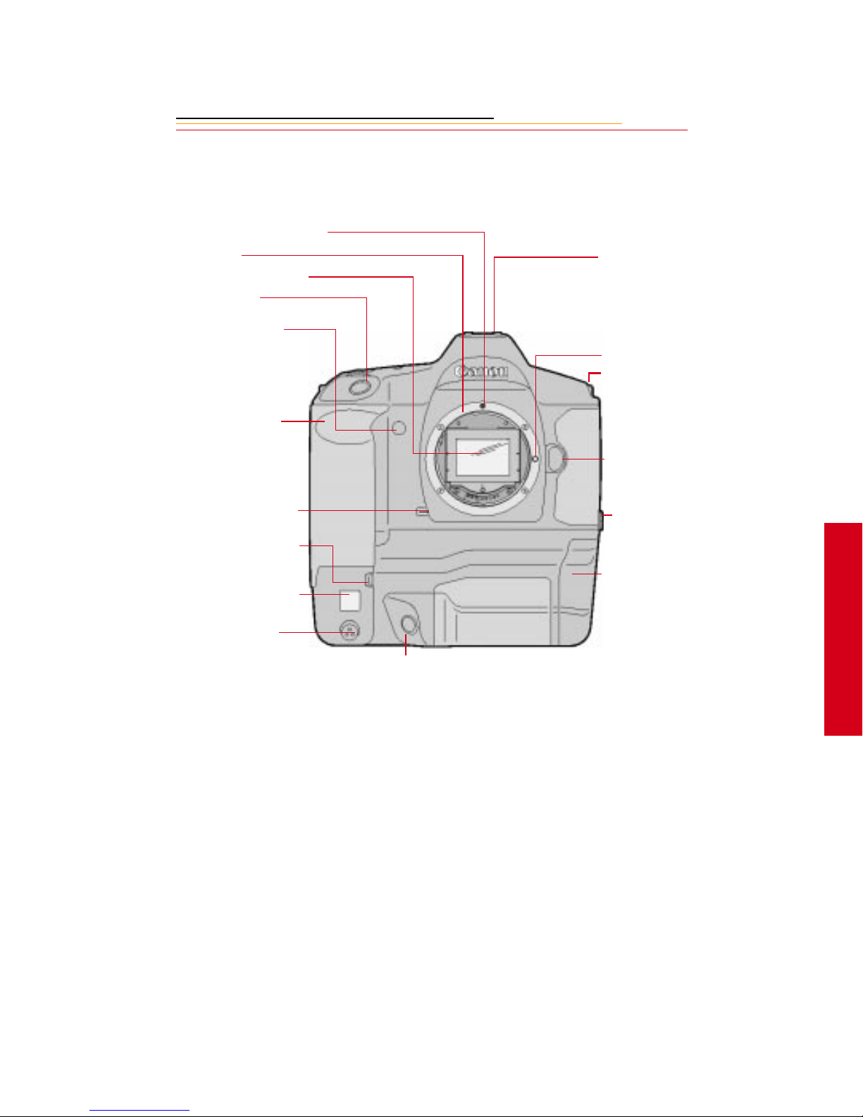
Camera Front
Lens Attachment Mark (red)
Lens Mount
Anti-aliasing or IR filter
Shutter Button
elf Timer Indicator
alm door (to access
ustom Functions)
X Contacts (for flash
attachments)
Lens Lock Pin
Strap Attachment
Lens Release Button
epth-of-Field Preview
utton
ertical Control Switch
hite Balance Sensor *
anon Remote Port
Vertical Shutter Release
* With firmware version 3.09, or higher, white balance is accomplished using image data
PC T erminal (Cov er) for
flash sync (external)
Battery/PC Card door (to
access battery and PC
Card)
2
Your Camera
rather than the White Balance sensor.
☛ An IR filter is included with the base camera kit. An anti-aliasing filter is included
with the regular kit.
2-3
Page 26
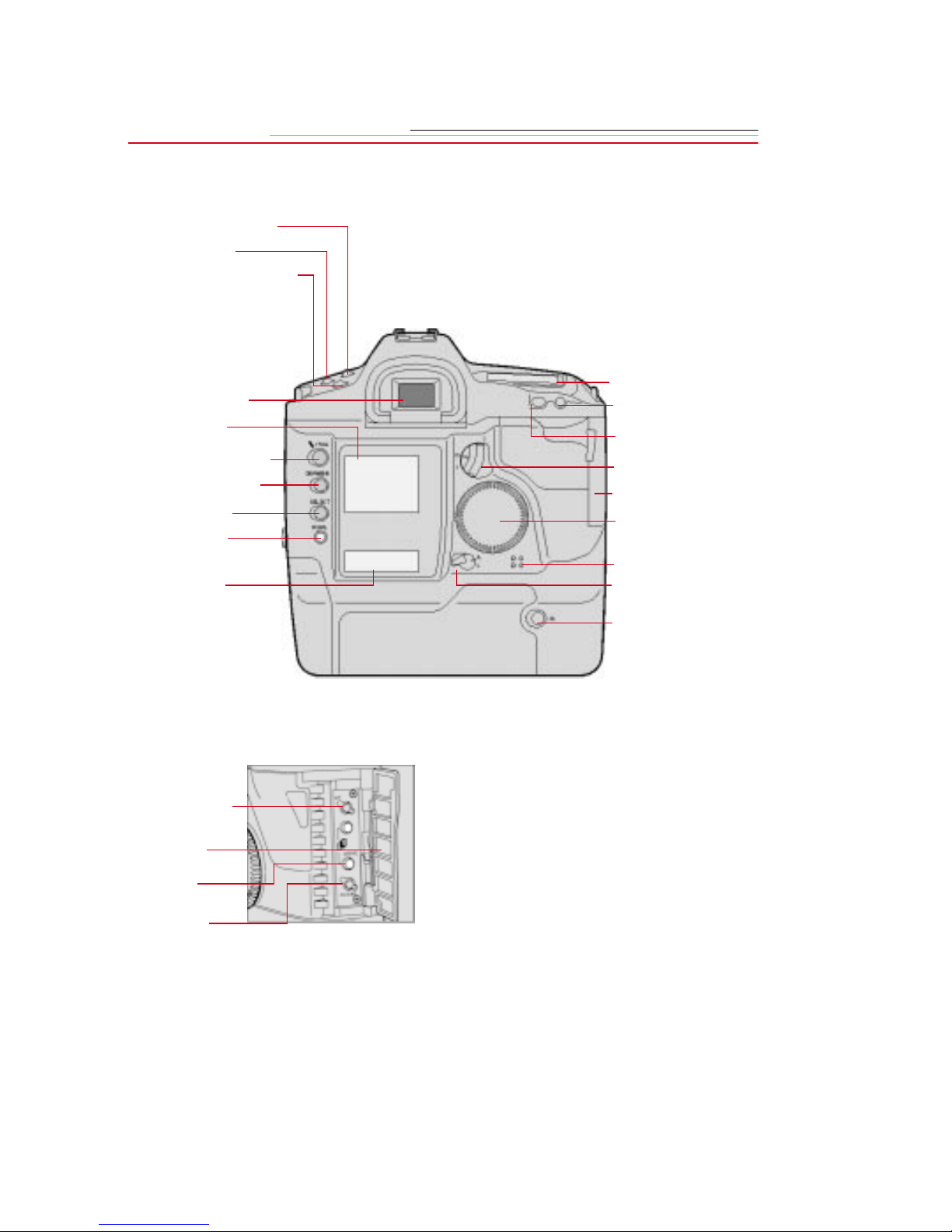
Camera Back
Shooting Mode Selector
AF Mode Selector
Metering Mode Selector/Flash
Exposure Compensati on butto n
Viewfinder Eyepiece
Image Display
RECORD/TAG button
DISP/MENU button
SELECT button
W.BAL button
Back LCD panel
Top LCD Panel
Focusing Point Selector
AE Lock button
Quick Control Dial
switch
Palm Door
Quick Control dial
Microphone
Main switch
Custom Function
button
Palm door
Drive Mode
selector
Clear button
Vertical AE Lock button
2-4
Page 27

Camera Top
X Contacts
Accessory Shoe
Shooting Mode Selector
AF Mode Selector
Metering Mode Selector/
Flash Exposure
Compensation button
Camera Bottom
Tripod Socket
LCD Panel Illumination
button
Exposure Compensation
button
Shutter button
Main dial
Top LCD panel
Strap Attachment
Data/Serial Number Label
2
Your Camera
2-5
Page 28

Camera Sides
Strap Attachment
Palm Door
AC Adapter Connection
IEEE 1394 Connection
Viewfinder Dioptric Adjustment dial
PC Terminal (Cover) for flash sync
(external)
Battery/PC Card Door
2-6
Page 29

Open Battery/PC Card Door
Battery in slot
Serial Port
Card Busy light
PC Card in slot
Eject button
2
Your Camera
2-7
Page 30

Top LC D P anel
Shooting Modes
Manual Exposure: M
Shutter priority AE: Tv
Bulb Exposure: bulb
Program AE: P
Aperture-priority AE: Av
Aperture Value
Custom Function
Control
AEB Value
Depth-of-field AE
Shutter Speed
ISO
Battery Check ( bc )
Bulb ( bulb )
Depth-of-field AE ( dEP )
Custom Function Control
Focusing Points
ISO Indicator
AF Mode Indicator
One-shot AF
AI Servo AF
Exposure Compensation
Value Index
Metering Modes
Evaluative Metering
Partial Metering
Fine Spot Metering
Flash Exposure
Compensation
AEB
Bulb Exposure Time
Self-Timer Countdown
2-8
Drive Mode Indicator
Single Exposure
Continuous Exposure
Self-Timer (10-second timer),
(2-second timer)
Exposure Level Indicator
Bulb Exposure Time
AEB Value Amount Indicator
Flash Exposure Compensation Value
Indicator
Custom Function Setting Indicator
Page 31

Back LCD Panel
Remaining Frames
Frame Number
White Balance
Auto
Daylight
Tungsten
Fluorescent
Flash
Battery Status Icon
PC Card Icon
Microphone Icon
Image Dis play
The Image D isplay has been designed for ease of use with maximized space for menu
choices and image-related information.
Menu Bar
The Menu bar is only displayed at your request. When you turn on the Image Display, the
last screen used appears without the Menu bar. If you then press the DISP/MENU button,
the Menu bar appears.
☛ Shortcut, press and hold the DISP/MENU button to turn on the Image Display and
display the Menu bar.
2
Your Camera
When the Menu bar is displayed, the remainder of the screen is grayed-out.
2-9
Page 32

When you select a Menu bar icon, the following screens appear:
Icon Function Dropdown Menu
Folder icon Displays the Folder
dropdown menu.
Menu icon Displays a
dropdown menu
with choices for the
Main, Properties,
and Custom Settings
menus.
Display icon Displays a
dropdown menu
with choices for
Single, Four, and
Nine Image Review
mode.
One PC Card:
Two PC Cards:
Contrast icon Di splays the Display
2-10
Contrast screen
where you can
adjust contra st
Page 33

Navigation Techniques
Use the following guidelines when navigating the Image Display
To display the Menu bar and
select a Menu bar icon
Press and hold the DISP/MENU
button and rotate the Quick Control
dial until the desired icon is
highlighted.
To display a Dropdown menu
Highlight the Folder, Menu, or
Display icon, and continue pressing
the DISP/MENU button until the
dropdown menu appears.
2
Your Camera
2-11
Page 34

To choose an item from a
dropdown menu
Continue to press the DISP/MENU
button and rotate the Quick Control
dial unti l th e desired menu choice i s
highlight ed.
To chose an item from a menu
screen
Press and hold the SELECT button
and rotate the Quick Control dial to
highlight your choice.
2-12
Page 35

Status Bar
A Status bar appears whenev er im a ges ar e displayed (Single, Four, or N ine I mage Review
mode). Information about the currently selected image appears on the Status bar:
The cu rrently active PC Card (if
there are two cards in the camera)
Two PC Cards
One PC Card
The currently active folder
Sound icon (if one or more sound
files are as socia ted with th e sel ected
image)
Tag icon (if th e selected imag e has
been tagged).
2
Your Camera
2-13
Page 36

V iewfinder
Focusing Points/Spot Metering Position Indicators
Exposure Level
Display
Fine Spot Metering
Area
Laser-matte
Screen Ec-Cll
Manual Exposure Indicator
AE Lock / AEB Indicator
Shutter Speed
Depth-of-Field AE Indicator
Aperture Value
Exposure Step Indicator
(1-stop, 1/3 stop)
Correct Exposure Indicator
☛ The viewf ind er represents the
actual live area of the CCD sensor.
☛ This illustration represents the
viewfinder for the DCS 520
camera. (The metering area is
larger for the DCS 560 camera.)
Overexposure Indicator
(+3 stops or more)
Exposure Level Indicator
Underexposure Indicator
(-3 stops or more)
2-14
Page 37

Using the Quick Control Dial
The Quick Control dial works in two different modes.
When you use i t in conjunction with the DISP/MENU bu tton, the SELECT button,
✔
or the W.BAL button, you can access digital functions through the Image Display
or the Back LCD panel.
When you turn on the Quick Control Dial switch, and use the Quick Control dial
✔
without one of the buttons mentioned above, you can access a variety of
non-digital functions (page 2-16).
☛ The Quick Control dial is disabled for a short period of time after each exposure. If
you change a camera setting with the dial immediately after capturing an image,
check that the camera responded appropriately.
Using the Quick Cont rol Dial For Digital Functi ons
The Quick Control dial can access functions available through the Image Display or the
Back LCD panel when you use it in conjunction with one or more of the following
buttons:
✔ DISP/MENU
SELECT button—Scroll through images or select menu options.
✔
W.BAL button—Select a White Balance option.
✔
button—Scroll through menu bar icons.
Press and hold one or more of the
buttons listed above and rotate the
Quick Control dial to access the
desired digital function.
2
Your Camera
2-15
Page 38

Using the Quick Control Dial For Non-d ig ital Functions
The Quick Control dial is also available for other functions when the Quick Control Dial
switch is set to the On po sition. T hese functions include:
Exposure compensation (page 8-37)
✔
Manual exposure (page 8-26) and Bulb exposure (page 8-28)
✔
Flash exposure compensation (page 8-54)
✔
Custom functions F5 and F11 (page 6-3); Various combinations of these two
✔
functions modify the way you set shutter speed and aperture value.
1 Set the Quick Control Dial
switch to On (|) to access the
functions list ed above .
2 Refer to the appropriate section
of the manual f or informa tion on
the desired functions.
When finished, set the switch to
Off (0), to avoid accidentally
changing a camera setting.
2-16
Page 39

Buttons
There are four buttons which access or change your camera’s digital functions when used
in conjunction with the Quick Control dial, the Image Display, and the Back LCD panel.
RECORD/TAG Button
Press and release the button to tag (or untag) the currently selected image. For
✔
example, you can tag images that you do not wish to delete. Refer to “Tagging
Images” on page 11-8.
Press and hol d the button and speak into th e micr ophone to record a sound fil e and
✔
associate it with the current image. Refer to “Associating Sound Files With
Images” on page 11-9.
DISP/MENU Button
Press and release the button to turn the Image Display on or off.
✔
Press and hol d the bu tton a nd use th e Qui ck Contr ol dia l to scrol l thr ough the menu
✔
bar icons.
SELECT Button
Press and hold the button and use the Quick Control dial to scroll through images
✔
or menu options.
Release the button to select the desired image or menu option.
✔
2
Your Camera
Hold down the
✔
turn the Image Display on and display a dialog box where you can delete the
currently selected image. Refer to “Deleting a Single Image” on page 11-11.
W.BAL button
Press and ho ld the but ton an d use t he Quic k Contro l dia l to s elect the de sire d Whit e
✔
Balance icon on the Back LCD panel. If no White Balance icons are visible, then
Custom White Balance is enabled. Refer to “White Balance” on page 8-1.
DISP/MENU
button and the SELECT button at the same time to
2-17
Page 40

Attaching the Lens
AF
M
M
AF
4
1
:
1
m
m
0
8
22
22
1 Remove the lens rear dust cap
and the camera’s body cap by
turning them counterclockwise.
2 Align the red dots on the lens
and camera body, then rotate th e
lens clo ckwise until it locks in
place with a click.
3 Set the lens Focus Mo de switch
to (AF).
2-18
AF
M
50mm
☛ Autofocus is not possible
when t he switch is set to ( M).
☛ During autofocusing, do not
touch the rotating part of the
lens.
☛ Some Canon lenses are
manual focus only.
Page 41

F
5
E
0
S
m
A
C
N
O
N
A
P
A
N
E
L
N
ULTRASONIC
J
IN
m
1
L
E
E
N
D
S
A
M
Removing the Lens
M
AF
4 Remove the front lens cap.
:
1
4
C
A
N
O
N
To remove the lens, press the Lens
Release button and turn the lens
counterclockwise.
N
2
When the lens is removed from the camera, place it face down on a stable surface to
☛
prevent damage to the electronic contacts.
Your Camera
2-19
Page 42

The Imager
The imager is the component of the camera that records light when you capture an image.
The DCS 520 imager is 2 million pixels and operates at 200 - 1600 ISO. The DCS 560
imager is 6 million pixels and operates at 80 - 200 ISO.
Anti-aliasing filter
Your camera conta in s an anti -ali asing fi lter which hel ps to prevent aliasi ng at cer tain foca l
distances.
☛ Refer to page 9-12 for
information on the effect of
the anti-aliasing filter on
focus.
IR Filter
The DCS 520 camera (base camera kit) uses an IR filter in place of an anti-aliasing filter.
2-20
Page 43

Illuminating the LCD Panels
Top LCD Panel
You can illuminate the Top and
Back LCD panels for easy viewing
at night or i n low l ight situ ation s. To
do so, press the Panel Illumination
button. The panels remain
illuminated for approximately six
seconds. To turn off the illu mination
before six seconds elapse, press the
Panel Illumination button again.
The LCD panel illumination goes
out au tomatically approxima tely
two seconds after you capture an
image.
☛ You can keep the Top and
Back LCD panels illuminated
longer than six seconds by
pressing any operation button
again while the illumi nat i on
timer is activated.
2
Back LCD Panel
☛ The LCD panels cannot be
illuminated during bulb
exposures.
Your Camera
2-21
Page 44

Camera Straps
Two camera straps are included with your camera. You can attach either or both.
Attac hing the Nec k S trap
Thread the ends of the neck strap
through the strap fixtures as shown.
Pull firmly on t he strap to make sure
it is held securely by th e buckles.
CAUTION:
If you are planni ng to use both
the neck strap and the hand
strap at the same time, follow
the instructions for attaching
both the hand strap and neck
strap (descri bed on page 2-24).
Failure to attach the straps
properly c an caus e t he camer a
to drop.
Attach ing the Hand S tra p
2-22
1 Thread the strap through both
loops in the hand strap pad.
2 Place the three-holed buckle on
the strap and thread through the
camera’s top strap fixture.
3 Thread the oth er end of the str ap
through the camera’s bottom
strap fixture .
Page 45

4 Thread the top strap back
through the buckle as shown.
5 Thread both ends of the strap
back through the loops on the
hand strap pad.
6 Place the two-holed buckle on
the top strap.
7 Tuck the top strap through the
bottom loop in the hand strap
pad.
8 Thread the bottom strap through
the two-holed buckle as shown.
9 Tuck the bottom strap through
the top loop in the hand strap
pad.
2
Your Camera
2-23
Page 46

Attachin g the Hand Strap and Neck Strap
1
Attach the Hand Strap
(page 2-22).
2 Thread the neck strap through
the three- hol ed buc kl e as shown.
2-24
Page 47

INSERT
PHOTO
HERE
Powering Your
Camera
3
You must operate your camera using either battery or AC power. An AC adapter is
included with your camera (except with the base camera kit). Batteries are available
through your camera dealer. Preserve battery power by using the AC adapter while
working indoors or when your camera is connected to a computer.
Use a battery charger and an international power cord set with your camera. The power
cords allow you to use the AC adapter and the battery charger in Australia, Britain,
Germany, Japan, and the United States.
Tu rnin g th e Ca me ra On a nd Off
Set the Main switch to (A) to turn
the camera on. ( Set it to ( ) to turn
the camera off.
A = Active
L = Locked
L
3
Power
3-1
Page 48

Batteries
Your camera provides up to the following number of images per fully-charged battery:
Camera NiMH battery NiCd battery
DCS 52 0 1000 300
DCS 56 0 300 100
Extended camera metering, focusing, or Image Display operation reduces the number of
images available from a charge.
☛ Battery performance deteriorates in temperatures below 32°F (0°C). Keep the
camera and especially a spare battery close to your body or in an inside pocket to
keep it warm until use.
WARNING:
All batteries can explode or cause burns if disassembled, shorted, exposed to high
temperatures, or disposed of in fire. Be sure to observe all precautions indicated on
the battery packag e. Alway s k ee p batte ries ou t of the reach o f ch ildren and f ollo w the
instructions on the battery label for recycling when you are finished with them.
CAUTION:
If you don’t plan to use you r camera for five or more days, you should rem ove the
battery fro m the camer a and carrie r.
damage due to battery leakage.
3-2
This will prevent battery discharge, and/or
Page 49

Inserting/ Re moving Batteries
You must ch arge a batt ery before using it for the first time.
☛
1 If the camer a is on, check the PC
Card icon on the Back LCD
panel.
IMPORTANT:
If the icon is blinking, wait until
it stops before continuing. (You
can lose data if you remove the
battery while the card is busy.)
2 Turn off the camera.
3 Place your index finger on the
Battery/PC Card door switch
and press downward while
opening the door with your
thumb and finger.
3
Power
3-3
Page 50

IMPORTANT:
Be sure that the red warning
light is off before continuing.
4 To insert: slide t h e ba tt er y to the
back of t he ba tter y sl ot a nd pr ess
firmly in place.
To remove: slide the battery out
of the battery slot.
5 Close the Battery/PC Card door.
☛ You can insert or remove a
battery while the camera is
connected to the AC ad apter.
IMPORTANT:
3-4
The battery can be inserted
incorrectly, but it will not fully
seat into the camera. Do not
force the battery into the
camera. Insert the end with the
slots, pointed down, and press
lightly to seat the battery
contacts.
Page 51

Checking Battery Stat u s
You can determine whe ther a batte ry need s ch arg ing by vi ewing t he Batt ery Sta tus ic on on
your camera’s Back LCD pane l. (I f the camera is using the AC adapter, the Bat te ry icon is
not displayed.)
1 Insert a battery in the camera
(page 3-3).
2 Tur n on t he camera.
3 Check the Batte ry Status icon on
the Back LCD panel.
The icon indicates whether the
Full
battery needs changing.
☛ The Bat tery Check function on
1/2 full
the Top LCD panel does not
function with this camera.
Low
Empty
Always check the battery status at the following times:
When loadin g a new battery
✔
After lengthy storage
✔
If the shutter will not release
✔
In cold weather
✔
Before an important shooting assignment
✔
3
Power
3-5
Page 52

Battery Charger
You will need to charge a battery before using it for the first time, then whenever it is low.
If you plan to use your camera without the AC adapter f or an extended perio d of t ime, it is
a good idea to charge one or more batteries before you begin. An external battery charger
is included with your camera (except with the base camera kit).
For the best results, store and use the battery charger within the following temperature
ranges:
Storage temperature range: -25°C to 70°C (-77°F to 158°F)
Charging temperature range: 0°C to 45°C (32°F to 113°F)
The battery charger has two slots. Lights near the slots illuminate to indicate the status of
the batteries as follows:
Yellow light Green light Battery Status
Off
On
Off
Slow Flashing
Fast Flashing
* Although you can use a bat t ery when t he l i ght turns green, you will have opt imal re sul ts
if you leave the battery in the charger for 2 hours after the light turns green.
Off
Off
On *
Off
Off
No battery inserted
Charging
Fully charged
Conditioning (Discharging)
Error
☛ Batteries can be recharged approximately 500 times.
3-6
Page 53

To Charge Ba tteries
1
Remove the battery from the
camera (page 3-3).
2 Plug the cable from the AC
adapter for charger into the
battery charger jack.
3 Select the internation al power
cord that is appropriate for your
area.
4 Plug th e power cord into a wall
outlet .
3
Power
3-7
Page 54

5 Insert one or two batteries into
the battery charger slots.
On average, the charger will
completely charge a battery in
approximately one hour. If two
batteries are inserted, they are
charged sequentially.
6 Once th e green light tu rns on,
wait two hours then remove the
battery or batteries from the
charger.
If you don’t wait two hours,
batteries will only be charged to
80% of capacity.
7 Insert a charged battery into the
camera.
8 Close the camera door.
The Ba ttery ico n appears on the
Back LCD panel when there is a
battery in the camera, the
camera is on, and the camera
has not entered PowerSave
mode. Refer to “PowerSave
Mode” on page 3-10.
The Battery icon i s not di splayed
if the AC adapter is connected.
If your battery charger does not function as expected, check the following:
Be sure the wall adapter is properly connected.
✔
Be sure there are no foreign objects lodged in the pockets.
✔
Be sure the batteries are inserted so that they properly mate with the connector in
✔
the bottom of the pocket.
☛ No harm wi ll come to your batteries i f yo u l eav e t h em i n t he c harger for an exte nded
period of time.
3-8
Page 55

Conditioning
From time to time you may need to condition (discharge) a battery. You would only do so
if a battery provides a noticeably shorter run tim e (less than 50% of normal capacity).
IMPORTANT:
Don’t condition your batteries too often or they will wear out prematurely.
1 Insert one or tw o bat teries in the
battery charger slots.
2 Press the Condition buttons
associated wit h the bat teri es tha t
you wish to condition.
The ba ttery wi ll first be
conditioned, then charged. The
whole process can take up to
5 1/2 hours.
3 Remove the batteries from the
battery charger when the lights
turn green.
☛ You can condition a battery in
one slot while charging a
battery in the other.
3
Power
3-9
Page 56

Battery Conservation
PowerSave Mode
PowerSave mode minimizes drain on your battery.If your camera is running on a battery,
and you don’t touch it for 30 minutes, it will enter PowerSave mode (go to sleep).
Waking your Camera from PowerSave Mode
Lightly press the Shutter button.
Six Second Timeout
When you release the Shutter button after pressing it halfway, the Top LCD panel, Back
LCD panel, and viewfinder displays remain illuminated for six seconds.
Situations Us in g Ex tra Battery Power
Use of a telephoto or wide angle fisheye lens and constant auto-focusing
✔
Frequent use of the Image LCD panel
✔
Cold temperatures
✔
Turning the camera on and off frequently
✔
3-10
Page 57

Image Display Timeout
The Image Display can drain your battery considerably. To minimize the drain, the Image
Display turns off if you have not performed any camera activities for 60 seconds.
☛ The Image Display does not turn off if the AC adapter is connected.
To Restore the Image Display
Press the DISP/MENU button.
3
Power
3-11
Page 58

AC Adapter
An AC adapter is provided with your camera (except with the base camera kit). Use the
AC adapter when wor king indoors to less en drain on the batter y. You will also want to u se
it when connected to a computer to prevent loss of power if the battery should lose its
charge.
The AC adapter does not have an On/Off switch. To turn off the AC adapter, unplug it
CAUTION:
Operate the equipment only from the type of power source indicated on the AC
adapter. A line voltage outside of this range can destroy the AC adapter and/or
the camera.
IMPOR TANT:
Use only the AC adapter included with your camera or available from Kodak as an
accessory. Do not plug other chargers or adapters into the camera.
Do not use the AC adapter for any purpose other than for the camera.
The AC adapter is for indoor use only.
3-12
Page 59

Connecting the AC Adapter
1 Open the small door on the side
of the camera.
2 Plug the AC ada pter i nto the AC
Adapter connection.
3 Select the universal power cord
that is appropriate for your area.
4 Plug the appropriate end of the
power cord int o the AC adapter.
5 Plug th e power cord into a wall
outlet .
The AC adapter will NOT charge a battery in the camera.
☛
☛ You can connect or disconnect
the AC adapter whil e a batt ery
is in the camera.
3
Power
3-13
Page 60

INSERT
PHOTO
HERE
4
As you capture images, they are stored on a PC Card (PCMCIA card) in your camera.
Before capturing images, you may want to prepare your camera so that the images are
stored acc ordin g to yo ur needs. T his ch apter descr ibes t he use of t he P C Card an d provi des
instructions for storing images.
Using PC Cards
PC Cards
Your camera is designed to accept Type II or Type III PC Cards, which are compatible
with the PCMCIA-ATA interface standard. Most hard disk drive and flash memory cards
may be used. Hard disk dri ve cards will hol d more i mages and ar e usual ly fast er tha n flash
memory cards, but flash memory cards are more rugged.
☛ PC Cards must be ATA-compatible.
4
PC Cards
IMPORTANT:
Use extr eme car e when h andlin g PC Car d s, as the y ar e easi ly dama ged. If dr o pped, th e
PC Card may be destroyed, resulting in the loss of all data on the card.
4-1
Page 61

Dual Slots for PC Cards
Your camera has t wo PC Card slots. With Typ e I I PC Ca rds, you can use one or both slots.
With Type III PC Cards, only one slot can be used. The card in the bottom slot is referred
to as CARD0, and the card in the top slot is referred to as CARD1.
CARD1
CARD0
If using only one card, insert it in either slot. With two cards, the first card inserted is the
active card. When you capture or delete images, they are saved to or deleted from the
active card.
IMPOR TANT:
Your camera uses 3 volt or 5 volt PC Cards. When you use two cards, they must both
have the same voltage. If you insert two cards with different voltages, neither is
powere d. A “Car d Voltage Mix” mess age wil l appe ar. Y ou woul d need t o r emov e one o f
the cards so that the other can be powered.
4-2
Page 62

Inserting/Removing PC Cards
4
It is not necessary to turn off the camera before inserting or removing a card.
To Insert or Remove a PC Card
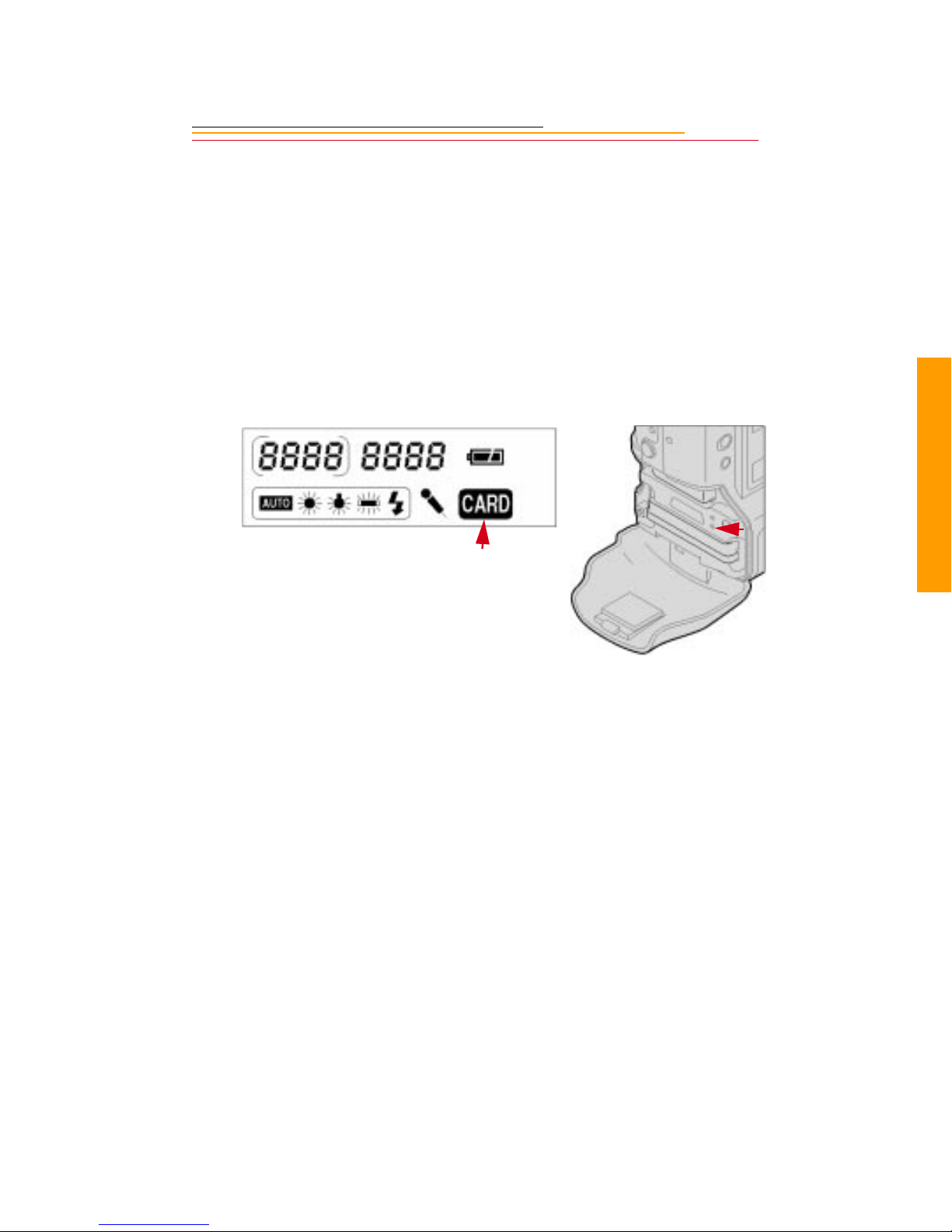
1 Check the Card icon o n the Back
LCD panel. It blinks when a
card is busy.
IMPORTANT:
Do not remove a card while the
icon or the Card Busy light are
blinking. (You can lose data if
you remove the PC Card while it
is busy.)
2 Place your index finger on the
door latch and press downward
while opening the Battery/PC
Card door with your thumb and
finger.
PC Cards
4-3
Page 63

IMPORTANT:
Before continuing, be sure that
the red warning light is not
blinking.
3 To insert: s lide the PC Card all
of the way into the lower slot
and press firmly.
4-4
☛ A label inside the door
indicates the proper position
for the card.
Page 64

To remove: press the Eject
button and pull the PC Card out.
4 Close the Battery/PC Card door.
The Card icon is displayed on
the Back LCD panel when there
is a card in the camera.
4
PC Cards
4-5
Page 65

Formatting a PC Card
As a precaution against formatting the wrong card, there can only be one card in the
camera when you format. Format the card using either the quick format or the full format
feature.
IMPOR TANT:
Quick format, while faster, is not recommended if there is a possibility that there are
defects on the PC Card media.
The Recover function only works if a PC Card has been formatted on the camera.
1 Select the Menu icon, then
choose Main Menu from the
dropdown menu. Refer to
“Navigation Techniques” on
page 2-11.
2 Select Card from the Main
menu.
The Card menu appears.
3 Choose Quick Format or Full
Format.
If two cards are in the camera,
you are prompted to remove the
inactive card. For example, if
CARD0 is active, you are
prompted to remove CARD1.
4-6
Page 66

4 Remove the inactive card, then
select Retry.
If you remove the active card,
the message at the left appears.
5 Re-insert the card in the proper
slot, then select Retry.
A confirmation screen appears.
6 Select Yes or No.
If you choose No, the Main
menu appears and the ca rd is not
formatte d.
If you choose Yes, the card is
formatted. A Progress screen
appears.
If you wait for the progress bar
to go to completion, a full
format occurs. If you press the
Cancel button, a quick format
occurs. With a quick format, t he
card will be usable, but
occasional errors may occur
when you save images.
4
PC Cards
4-7
Page 67

Selecting a PC Card or F o lder
Images are stored on the PC Card in folders. There is always at least one empty folder on
the card. Whe n you store an image i n a n empty fo ld er , a new em pty fol der i s autom ati cally
created. The new folder is called FolderX, with X being the next number available.
Selecting a PC Card or Folder
1
Select the Folder icon
(page 2-11).
If there is no PC card in the
camera, an X ap pea rs wi thin the
Folder icon. Se lecting the icon
produces this screen.
With one PC Card, this
dropdown menu appe ars with a •
displayed next to the currently
active folder.
4-8
With two PC Cards, th is
dropdown menu appe ars with a •
displayed next to the currently
active card and the currently
active folder on that card.
A 0 or 1 appears in the Folder
icon, indicating the active PC
Card.
The listed folders are on the
active card. The folder list
changes when you change cards.
2 With two PC Cards, s elect
CARD0 or CARD1 from the
dropdown menu (page 2-11),
then select a folder. With one
card, select a folder.
Page 68

Saving Files
5
JPEG and TIFF File Processing
The DCS 520 camera supports background i mage pr ocessing that produces JPEG or TIFF
RGB files that can be opened directly by any image editing software. This feature is not
currently available on the DCS 560 camera.
The choices for processed files are JPEG Good, Better, Best, and TIFF RGB. JPEG Good
files have the most compression, JPEG Best have the least. The less compression, the
better the quality of the processed file and the larger the file size. The file size varies,
depending on content. TIFF RGB files are not compressed.
When you capture images, they are written to the selected folder using the TIFF Custom
format, regardless of whether processing is turned on. If you turn on processing, JPEG
Best, Better, Good, or TIFF RGB files are created and saved when the camera is not busy
with other tasks such as capturing images.
JPEG files are saved to a JPEG folder and TIFF RGB files are saved to a TIFF folder.
These folders are created on the PC Card when you turn on processing (if they don’t
already exi st). I f you se lect the JPEG or TIFF folder to rev iew im ages, t hen you ca pture an
image, a mess age inf orms you th at image s ca nnot be sa ved the re. You can specify whether
the original TIFF file is save d or dele ted once the JPEG or TIFF RGB file is sa ved.
The default for pr ocess ing is Off . When yo u turn on pr ocess ing, it stays on unti l you t urn i t
off, or remove the PC Card.
5
Saving Files
Processing with Two PC Cards
When you have PC Cards in both slots, images are processed on the card that is active
when you turn on processing. If you make the other card active, processing continues on
the inact iv e ca rd . For ex ampl e, i f CARD0 i s a ct ive when you turn on proces si ng, t he n yo u
change to CARD1, processing continues on CARD0, but not on CARD1. In this case, if
you want to sw itch processing to CARD1, you must turn off processing, then turn it back
on. When turned on, processing is automatically set for the active card (CARD1).
5-1
Page 69

Processing Images
1
Select the Menu icon, then
choose Main Menu from the
dropdown menu. Refer to
“Navigation Techniques” on
page 2-11.
2 Select Proces sing from the Main
menu.
The Pr ocessing menu appe ars. If
two PC Cards are inserted, the
active card is indicated, for
example, All on CARD1.
3 Select your choice.
Choice Images Processed
OFF Turns off processing
Tagged
in folde r
All tag ged imag es in
the selected folder on
the active card
All in
Folder
Tagged
Images
All on
Card
Change
Settings
The Processing confirmation
screen appears.
All images in the
selected folder on the
active card
All tag ged imag es on
the active card
All images on the
active card
Displays a screen
where you can change
processing settings
(page 5-5)
4 Select OK to begin processing
or Cancel to retu rn to the Main
menu without processing.
5-2
Page 70

When you enable Processing, certain conditions may exist which will cause other screens
to appear, as shown in the table below.
Condition Screen Your Action
There is no PC Card in the
camera.
Processing is ena ble d for the
selected folder and there are no
images in the folder.
Similar screens appear when the
same condition exists for tagged
images or for all images on the
card.
Processing is ena ble d for the
selected folder and all images in
the folder have been processed.
Similar screens appear when the
same condition exists for tagged
images or for all images on the
card.
Click OK and insert a
PC Card.
If you click OK, new
images are processed
when you capture them
to that folder.
If processing is enabled
for tagged images or all
image s on the c ard, then
images are processed as
you tag or capture them.
If you click Cancel,
processing is not started.
5
Saving Files
There are two PC Cards in the
camera. With processing enabled
for one card, you make the other
card active, then access the
Processing menu.
If you click OK,
Processing continues on
the inactive car d.
If you click Cancel,
processing st ops on the
inactive card. You can
then enable processing
on the a ctive card, if
desired, if desired.
5-3
Page 71

Condition Screen Your Action
Your processing settin gs a re set to
delete the original TIFF image
when you process files. Refer to
“Changing Processing Settings”
on page 5-5.
The active PC Card becomes full
as images are being processed.
This can occur regard less of
whether there are one or two cards
in the ca mera.
You remove a PC Card while
processing is enabled (whether or
not images are currently being
processed).
If you click OK, a
second confirmation
screen appears.
If you click Cancel,
Processing i s not sta rted.
The Processing menu
appears.
Click OK and delete
some images or insert a
different card.
5-4
Page 72

Changing Processing Set ti ngs
There are several processing settings that you can change. The settings are applied to
images as they are processed.
1 Select Change Settings from the
Processing menu.
The Processing Settings menu
appears with the current values
shown in parentheses.
5
2 Select the desired setting.
Processing
Settings
Original TIFF Save
File Type JPEG Best
Screen
Defaults
Underlined
Delete Delete s the TIFF
Good, TIFF RGB
The following screens appear,
depending on your choice:
Result
Saves the TIFF image
(default).
image after the
processed JPEG file
has been saved.
, Better,
Files are processed to
the selected JPEG
quality.
Saving Files
Resolution 100%
Maintains the size an d
spatial resolution of
the original im ag e.
67% The size and spatial
resolutio n are reduced
to two- thirds.
50% The size and spatial
resolutio n are reduced
to one-half.
5-5
Page 73

Processing
Settings
Screen
Defaults
Underlined
Result
Noise
Reduction
Yes
Noise is reduced in
processed images.
No Noise is not reduced.
Look Portrait Applie s a lower
contrast tone scale
with more de tail in t he
highlights and
shadows.
Product
Applies a higher
contrast, mo re vib ran t
tone scale.
Sharpening
Level *
None
No sharpening is
applied to th e fi nished
image.
High Progressively less
Medium
sharpening is appl i ed
to the finished image.
Low
Exposure Yes Automatic exposure
compensation is
applied
No Automatic exposure
compensation is not
applied
* The Sharpening Level setting in the Processing menu determines whether sharpening is
applied when images are processed on the camera. The Sharpening property in the
Properties menu determines whether sharpening is applied by the DCS Host software.
5-6
Page 74

Workin g with TIFF Custom Files on yo ur Computer
If you don’ t pro cess i mage s on your camera , you nee d t o use o ne of t he fol lowing softwa re
applications to work with the TIFF Custom files. (The TIFF Custom file format is
proprietary to Kodak.)
File Format Module
✔ This software appl ic ati on allows you to open high resolut io n TIFF Cus to m im ages
directly into Photoshop.
DCS Acquire Module or DCS TWAIN Data Source
✔ These are full-featured image editing and acquire software applications.
If the DCS Host Software CD (included with your camera) includes the DCS Acquire
Module and DCS TWAIN Data Source version 5.8 or later , you will be giv en the opt ion of
installing t he DCS Fil e Fo rmat M odul e. I f the CD i ncl udes a version prior to 5 .8, t he DCS
File Format Module is not included. To download the DCS File Format Module, visit the
Kodak Web site (www.Kodak.com).
☛ If you attempt to open TIFF Custom files in Photoshop without using the DCS File
Format Module, the DCS Acquire Module, or DCS TWAIN Data Source, only the
thumbnail version will be available, yielding a less than optimal image resolution.
5
Saving Files
5-7
Page 75

IPTC Data Management
This feature allows inclusion of International Press Telecommunication Council (IPTC)
data as pa rt of t he image header. You enter t he I PTC data on your computer using the DCS
Acquire Module or DCS TWAIN Data Source (version 5.8 or later) and save it to a PC
Card. (Refer to the KODAK PROFESSIONAL DCS Host Software User’s Manual.)
Once IPTC data has been saved to a PC Card, you can load the data into your camera
(page 5-9).
1 Select the Menu icon, then
choose IPTC Data from the
dropdown menu. Refer to
“Navigation Techniques” on
page 2-11.
2 Select your choice from the
IPTC Data menu:
None—No IPTC data is written
to the image headers.
IPTC Data File—If there is an
IPTC file on the camera, it is
displayed. Choosing this option
writes the IPTC data to the
image header.
5-8
Load from Card—You can
load an IPTC file from a PC
Card. Refer to “Loading IPTC
Data from a PC Card” on page
5-9.
Page 76

Loading IPTC Data from a PC Card
1
With the IPTC Data screen
displayed (page 5-8), choose
Load from Card.
The Load IPTC Data screen
appears with a list of the IPTC
files on the acti ve PC Card. (I f
only one card is in the camera,
the card choices do not appear.)
2 Press and hold the SELECT
button and rotate the Quick
Control dial to choose the
desired card. (You may need to
scroll up to the card choices if
there are numerous IPTC files.)
3 Repeat step 2 to choose an IPTC
file.
5
Saving Files
The file is loaded from the PC
Card to your camera.
Each file must have a unique
name. If you attempt to load a
file with the same name as one
on your camera, a message asks
if you want to replace the
existin g file.
5-9
Page 77

INSERT
PHOTO
HERE
Configuring Your
Camera
6
This section describes how to change various camera settings such as the ISO and Drive
modes, allowing you to precisely configure the camera for specific shooting situations.
Set the cam era’s Main switc h to (A).
Date and Time
You can set the date and time to be associated with each image captured. The format for
the date is year/month/day and the format for time is hour:minute:second based on a
twenty-four-hour clock. The setting is maintained when you turn off the camera, after
Powersave, or when you remove the battery for a few days.
☛ There is a small rechargeable battery in the camera than can lose its charge if you
remove the main battery for a long period of time. In this case, you would need to
reset the date and time after replacing the main battery.
1 Select the Menu icon, then
choose Main Menu from the
dropdown menu. Refer to
“Navigation Techniques” on
page 2-11.
6
Configuring
6-1
Page 78

2 Select Date/Time from the Main
menu.
The Date/Time screen appears.
There are si x fields : year, month,
day , a nd h our, minutes, sec ond s.
3 Press and hold the SELECT
button and rotate the Quick
Control dial to change the
highlighted field.
4 Release the SELECT button to
accept the change and highlight
the next field.
To leave a field unchanged,
press and release the SELECT
button without using the dial.
☛ When the second s fie ld is
highlighted and you press the
SELECT button, the seconds
stop counting.
Dioptric Adjustment of the Viewfinder
The viewfinder has a built-in dioptric adjustment mechanism that lets you adjust the
eyesight correction to achieve a sharp viewfinder image. This allows near-sighted or farsighted users to capture images without wearing glasses. The diopter can be adjusted
within a range of –3 to +1 dpt.
Look into the viewfinder and turn
the Dioptric Adjustment dial in
either d i rection until t he five
focusing points or the fine spot
metering area mark appear sharp.
☛ The adjustment range is from
–3 dpt to +1 dpt (diopter). For
adjustment exceeding this
range, use one of the Dioptric
Adjustment Lenses available
from Canon.
6-2
Page 79

Custom Functions
A set of cust om fun cti ons is provided to l et y ou t ail or the camera’s functions according to
your personal preferences and shooting style. Full descriptions of each custom function
are provided later in this cha pte r . Twelve custom functio ns are avai labl e, and ea ch of them
has at least two settings. Some have more than two settings. The default setting for each
custom function is 0 (for example, F-9-0). All other settings are optional, (for example, F9-1, F-9-2, or F-9-3). Select one setting per custom function.
Selecting and Sett ing Custom Functions
1
Set the Main sw itch to (A).
2 Open the palm door and press
the Custom Function (CF)
button.
A custom function number is
displayed i n t he Top LCD panel.
3 2 1 1 2 3
0
3 Turn the Main dial clockwise or
counter-clockwise until the
desired custom f unction number
is displayed in the Top LCD
panel.
6
Configuring
6-3
Page 80

3 2 1 1 2 3
✔ Display example indicating that custom
functions 5, 10, and 14 are set.
0
4 While the custom function
number is displayed, press the
CF button to change the setting.
The number changes each time
the Custom Function button is
pressed.
Dots are displayed below the
exposure scale to indicate
optional custom function
settings that have been selected.
☛ A dot below “–2” indicates
that an optiona l setting for
custom function F-4 has been
selected. Dots for other
custom fun ctions appear to the
right or left of the “–2”
position.
6-4
☛ You can check the custom
function setti ngs at any time
by pressing the CF button to
activate the Top LCD panel.
5 Press the Shut ter b utton h alfway
to complete the setting and
restore the T op LCD panel to the
original display.
Page 81

Resetting Individual Custom Functions
3 2 1 1 2 3
0
Resetting All Custom Functions At Once
You can reset all custom functions to their default (0).
1 T o r eset a custo m fun ction to the
standard (default) setting, select
the custom function and then
press the CF button to change
the number in the Top LCD
panel to “0”.
2 Press the Shut ter but ton hal fway
to complete the setting and
restore the Top LCD panel to the
original display.
1 Set the Main sw itch to (A).
2 Open the palm door and press
the CF button.
3 Press the Clear butt on
6
Configuring
6-5
Page 82

Custom Function Chart
Type
Beeping
on/off
Focus
Custom
Function
No.
Affected Function
Top LCD Panel
Display
F-3 Beeping when in focus
F-4 AF Operation method 0
0
3 2 1 1 2 3
0
3 2 1 1 2 3
F-4 AF Activation 2
Setting
No.
0
1
1
6-6
0
3 2 1 1 2 3
Page 83

Operation
Useful Situatio ns
No beeping when subject is in focus.
Beeps when the subject is in focus.
Autofocus starts when the Shutter button is
pressed. Exposure is locked when AE
Lock button (T) is pressed.
Autofocus starts when the AE Lock button
(T) is pressed. Exposure is locked when
the shutter button is pressed halfway.
Autofocus starts when the Shutter button is
pressed halfway. Focus is locked when the
AE Lock button (T) is pressed.
Set to suit your shooting style and the
environment.
1: This option lets you carry out metering
and autofocusing independently.
2: For sports photography using focus
prediction in AI Servo AF mode, this
option lets you temporarily stop the
focus.
6
Configuring
6-7
Page 84

Type
Custom
Function
No.
Affected Function
Top LCD Panel
Display
Setting
No.
Exposure
F-5 Shutter speed and aperture value
setting method in Manual Exposure
mode
F-6 EV steps for the shutter speed,
aperture, exposure compensation,
flash exposure compensation, and
AEB
0
3 2 1 1 2 3
0
3 2 1 1 2 3
0
3 2 1 1 2 3
0
3 2 1 1 2 3
0
1
0
1
6-8
0
3 2 1 1 2 3
2
Page 85

Operation
+-+
Useful Situatio ns
Shutter speed is set by the Main dial.
Aperture value is set by Quick Control dial
or by combined operation of the Exposure
Compensation button ( ) and Main dial.
Aperture value is set by the Main dial.
Shutter speed is set by the Quick Control
dial or by combined operation of the
Exposure Compensation button ( ) and
the Main dial.
• For op er ati on when combined w i t h custom
function F-11, refer to “Comb ined Use of
custom functions F-5 and F-11” la ter in this
chapter.
Shutter speed, aperture value, exposure
compensation, flash exposure
compensation and AEB step amounts are
set in 1/3-stop increments.
Shutter speed and aperture value are set in
1-stop increments, and exposure
compensation and AEB step amounts are
set in 1/3 stop increments.
-
When making manual exposure
adjustments, this function lets you choose
whether to use the Main dial for adjusting
the shutter speed or aperture value. This
option is convenient for studio flash
photography where the shutter speed is
kept constant while the aperture is
frequently varied to alter the depth of field
and exposure.
This function lets you input shutter speed
and aperture settings in the desired
increment. 1/2-stop exposure
compensation settings are also possible,
providing wide flexibility to satisfy various
shooting styles.
6
Configuring
Shutter speed, aperture value, exposure
compensation, flash exposure
compensation, and AEB step amounts are
set in 1/2-stop increments.
6-9
Page 86

Type
Custom
Function
No.
Affected Function
Top LCD Panel
Display
Setting
No.
Focus F-7 Manual focusing with the electronic
manual focusing ring
0
3 2 1 1 2 3
0
3 2 1 1 2 3
0
1
6-10
Page 87

Operation
Useful Situatio ns
Manual focusing is possible.
• This function works only with lenses equipped
with an electronic manual focusing ring.
Manual focusing is prohibited.
• Manu a l f ocusing by setting t he Lens’ Focus
Mode switch to “M” is possible.
This option disables the manual focusing
capability of the electronic ring provided
on many USM lenses, eliminating the
possibility of accidentally turning the ring
and shifting the focus after autofocusing is
complete.
Compatible Lenses:
EF50/1.0L USM EF 85/1.2L USM
EF 200/1.8L USM EF 300/2.8L USM
EF 400/2.8L USM EF 500/4.5L USM
EF 600/4L USM EF 1200/5.6L USM
EF 28-80/2.8-4L USM
6
Configuring
6-11
Page 88

Type
Custom
Function
Affected Function
No.
F-8 Center-weighted average metering
Top LCD Panel
Display
0
3 2 1 1 2 3
0
3 2 1 1 2 3
Setting
No.
0
1
Exposure
F-9 AEB (Auto Exposure Bracketing)
exposure sequence
0
3 2 1 1 2 3
0
3 2 1 1 2 3
0
3 2 1 1 2 3
0
3 2 1 1 2 3
0
1
2
3
6-12
Page 89

Operation
Useful Situatio ns
Evaluative metering
Center-weighted average metering.
• The Top LCD panel still shows the evaluative
metering indication.
Under->Correct->Over
Under->Correct->Over
Correct->Under->Over
Correct->Under->Over
• 0 & 2: AEB operation is canceled when the
Main switch is set to ( ), the Lens is
exchanged, bulb exposure mode is set, flash
charge completion is detected, or the Clear
button is pressed.
• 1 & 3 AEB operation is not canceled when the
Main switch is set to( ) , the Lens is
exchanged. A EB mode can be selec te d by
simultaneously holding down the AF Mode
and Shootin g Mode selectors and turning the
Main dial
Setting this function to center-weighted
average metering provides you with a
predictable metering pattern for
determining exposure. This is useful for
experienced photographers who have
developed an ability to accurately
determine exposure combining average
metering and exposure compensation.
2, 3: These settings change the bracketing
sequence to “0 -> - -> +”, which is
useful when shooting live subjects or
changing scenes where the first shot
will most likely capture the best
expression of composition.
1, 3: These settings are useful if you
frequently use AEB, as it prevents
AEB mode from being ca nc eled every
time you change the lens and set the
Main switch to ( ). It lets you
activ at e A E B mode using an ext e rn al
setting operation, eliminating the need
to open the camera’s palm door.
6
Configuring
6-13
Page 90

Type
Custom
Function
No.
Affected Function
Top LCD Panel
Display
F-10 Elimination of AF frame display 0
0
3 2 1 1 2 3
0
3 2 1 1 2 3
Setting
No.
1
F-11
Focus
Focusing point selection
0
3 2 1 1 2 3
0
3 2 1 1 2 3
0
3 2 1 1 2 3
Mirror
operation F-12 Mirror up operation 0
0
1
2
6-14
0
3 2 1 1 2 3
1
Page 91

Operation
Useful Situatio ns
Focusing point superimposed (red)
Superimpose is prohibited
Focusing Point selector ( ) and Main
dial
Exposure Compensation button ( ) +
Main dial
Independent operation of Quick Control
dial or Exposure Compensation button
+
( ) + Main dial
-
• Focusing point selection using the Quick
Control dial is p ossi bl e during meterin g
operation when the 6-second metering timer is
activated, or during continuous shooting in A l
Servo AF mode.
• After the far left or far right focusing point is
selected, selection cannot proceed in the same
direction.
.....
+
-
You might use this option if you are
annoyed by the AF frame illumination in
the viewfinder, or if you frequently use
manual focusing to adjust the final focus.
0,1: This option makes it possible to match
your camera’s button operations to
existing EOS-1 or EOS 5-A2/A2E
cameras.
2: This option lets you track the subject
with the focusing point in real-time by
operating the Quick Control dial. This
can be useful when you are tracking a
moving subject using the Focus
Prediction control in AI Servo AF
mode.
6
Configuring
Normal operation
Mirror up operation
This is effective for preventing camera
shake caused by mirror operation shock
when making long exposures. Use of a
tripod is recommende d.
6-15
Page 92

Type
Custom
Function
No.
Affected Function
Top LCD Panel
Display
Setting
No.
Exposure F-13 Spot metering at the AF frame 0
0
3 2 1 1 2 3
0
3 2 1 1 2 3
Fill-in flash control
Flash
F-14
0
3 2 1 1 2 3
0
3 2 1 1 2 3
1
0
1
6-16
Page 93

Operation
Useful Situatio ns
Fine spot metering in center of image area.
Spot metering linked to the manually
selected focusing point.
• In automatic focusing point selection mode,
spot metering is carried out for the center
focusing point only.
Automatic flash output reduction control
active.
Automatic flash output reduction control
prohibited.
This function links spot metering to the
focusing point, allowing you to spot meter
the subject without changing the framing
of the scene.
This function prevents underexposure of
strongly backlit subjects, for example,
when you are shooting portraits backed by
light from the late afternoon sun.
6
Configuring
6-17
Page 94

Combined Use of Custom Functions F-5 and F-11
When custom functions F-5 and F-11 are combined, shutter speed and aperture value
settings are carried out as shown in the following table.
Custom Function No. F-5
Selection No.
0 Shutter speed:
Set by Main dial
01
Aperture value:
Set by Main dial
F-11
Aperture value:
1) Set by Quick Control dial or
2) Set by Exposure Compensation
+
button ( ) and Main dial.
1 Shutter speed:
Set by Main dial
Aperture value:
1) Set by Quick Control dial or
2) Set by Focusing Point
selector( ) and Main dial.
2 Shutter speed:
Set by Main dial
Aperture value:
1) Set by Quick Control dial or
2) Set by Focusing Point selector
( ) and Main dial.
-
..... .....
.....
Shutter speed:
1) Set by Quick Control dial or
2) Set by Exposure Compensation
+
button( ) and Main dial
Aperture value:
Set by Main dial
Shutter speed:
1) Set by Quick Control dial or
2) Set by Focusing Point
selector( ) and Main dial
Aperture value:
Set by Main dial
Shutter speed:
Set by Focusing Point selector
( ) and Main dial
-
.....
6-18
Page 95

Resetting the Camera to Its Initial Settings
Resetting All Cam era Functions
Reset all of the camera’s functions
(except for the cus tom fun ct ions) to
their default set ti ngs by ope ni ng t he
palm door and pressing the Clear
button. Afte r r es et ti ng, the camera’s
functions are set as shown below:
Function Setting
Shooting mode Program AE (P) mode
AF mode One-shot AF
Metering mode Evaluative metering
Drive mode
Sing le exposure ( )
6
Custom functions Not affected
Caution:
✔ When custom function F-8 is set for center-weighted average metering instead
of evaluative metering, and the metering mode is set to partial metering or spot
metering, pre ssi ng the Clear button wil l res et al l of the camera functi ons exc ept
for the Meteri ng mode, w hich remains at the current setting.
Configuring
6-19
Page 96

Resetting All Custom Functions
Reset all of the custom functions to
their initial settings by pressing the
Custom Function (CF) button
before pressing the Clear button.
6-20
Page 97

Camera Prope rt i es
You can set the following camera properties using camera controls: Display Off time,
PowerSave time, Enable Sharpening, Dropdown Menu Lag Time, Use FOLDER01,and
Resolution. You can also specify Custom Functions settings. The list of properties may
change as new versions of firmware become available.
Setting Display Off Time
Extended use of the Back LCD panel can drain your battery.
To change the length of time before the Back LCD panel turns off:
1 Select the Menu icon, then
choose Properti es from the
dropdown menu (page 2-11).
1 With the Properties menu
displayed, select Display Off
Time.
The Display Off Time screen
appears.
This screen (and the Powersave
screen) operate a little
differently than the others.
6
Configuring
2 Press and hol d t he DISP/MENU
button.
A vertical arrow appears at the
right of the screen.
3 While continuing to press the
DISP/MENU button, rotate the
Quick Control dial to c hange t he
highlighted number.
4 Release the DISP/MENU button
The vertical arrow goes away
and the changed number is
displayed on the screen.
6-21
Page 98

5 To highligh t a differ ent num ber,
press and hold t he DISP /M ENU
button.
A horizontal arrow appears at
the bottom of the screen.
6 While continuing to press the
DISP/MENU button, rotate the
Quick Control dia l to highligh t a
different number.
7 Release the DISP/MENU
button.
The horizontal arrow goes away
and the new number is
highlighted.
8 Repeat steps 2 through 7, as
needed. (The DISP/MENU
button toggles between the
vertical arrow that changes the
value of a number and the
horizontal arrow that selects a
different number.)
6-22
9 Select OK to establish the new
setting, or Cancel to retain the
original setting.
Page 99

Enabling Sha rpening
Some DCS 520 and 560 cameras are equipped with an antialiasing filter, an optical filter
that is mounted inside the camera in front of the electronic imager. This filter eliminates
unwanted color ar tif acts, a nd i mproves ov er all ima ge qua lit y at the expense of a s mall lo ss
of sharpness. Depending on your subject, you may or may not want to allow sharpening
when the i mage is processed. For example, you might want to sharpen an image of a pi ec e
of equipment, and might not want to sharpen a portrait or an image of clothing items.
☛ Some DCS 520 cameras (base camera kits) use IR filters instead of antialiasing
filters.
Sharpening can be applied in one of two places:
✔ In the DCS Host Software during image processing.
✔ On the camera when you process an image. Refer to “Processing Images” on page
5-2.
This section describes the camera’s Sharpening property which determines whether
sharpening is applied by the DCS Host Software’s “At Capture” setting in the Sharpen
Image prefe rence. If you set the Sh arp en Image s pref erence to “O n” (or “Of f”), i mages ar e
sharpened (or not), regardless of the camera property setting. Refer to the DCS Host
Software User’s manual.
☛ The Sharpening property has no impact on whether sharpening is applied during
processing in the camera.
6
Configuring
The default Shar pen ing property setting is Yes for DCS 560 cameras and No for DCS 520
cameras. If y ou remove the antialiasi ng fi l ter, set the Sharp eni ng pr operty to “Off”. Refer
to “Removing, Cleaning, and Re-installing the Anti-aliasing Filter” on page 14-3.
1 Select the Menu icon, then
choose Properti es from the
dropdown menu. Refer to
“Navigation Techniques” on
page 2-11.
2 Select Sharpening from the
Properties menu.
The Sharpening screen appears.
3 Choose No or Yes.
6-23
Page 100

Setting File Resolution
You can specify a file resolution to be saved in the header of subsequently captured
images. This property does not affect image processing in the camera, the DCS Acquire
Module, or the DCS TWAIN Data Source. Th e speci fied resol ution is u sed by ap plica tions
such as Photoshop when displaying the images.
1 Select the Menu icon, then
choose Properties from the
dropdown menu. Refer to
“Navigation Techniques” on
page 2-11.
2 Select Resolution from the
Properties menu.
The Image Resolution screen
appears.
3 Select Resolution or Units.
If you select Resolution, the
Resolution screen appears.
4 Press and hold the SELECT
button and rotate the Quick
Control dial to change the
highlighted field.
5 Release the SELECT button to
accept the change and highlight
the next field.
To leave a field unchanged,
press and release the SELECT
button without using the dial.
If you select Units, the
Resolution Units screen
appears.
6 Choose Pixels/inch or
Pixels/cm.
6-24
 Loading...