

Page 1

KODAK PROFESSIONAL
'&6'LJLWDO&DPHUD
)LUPZDUHYHUVLRQDQGODWHU
Page 2

This is an update to the DCS 300 Series User’s Manual. It describes new features
available on DCS 330 cameras with firmware version 3.2 or later.
Page 3

Table of Contents
New Look for the Image Display........................................................................ 2
Menu Bar ....................................................................................................2
Navigating the Image Display .................................................................... 5
Status Bar ....................................................................................................6
Dual Slots for PC Cards....................................................................................... 7
Selecting a PC Card or Folder .................................................................... 8
Deleting Images .......................................................................................... 9
Formatting a PC Card ............................................................................... 10
JPEG File Processing......................................................................................... 11
Processing with Two PC Cards ................................................................. 11
Processing Images ..................................................................................... 12
Changing Processing Settings ................................................................... 15
Working with TIFF Custom Files on your Computer .............................. 17
White Balance.................................................................................................... 18
Selecting White Balance ........................................................................... 18
Using Custom White Balance Settings ..................................................... 19
Intervalometer.................................................................................................... 25
Contents
Recovering Deleted Images............................................................................... 27
Name Plate......................................................................................................... 28
Global Positioning System................................................................................ 29
IPTC Data Management.................................................................................... 31
Loading IPTC Data from a PC Card ......................................................... 32
Sharpening......................................................................................................... 33
In the Camera ..................................... ........ ............................................... 34
In the DCS Acquire Module or DCS TWAIN Data Source ..................... 35
Serial Port Operation......................................................................................... 37
Connecting a Device to the Serial Port ..................................................... 37
Accessing Serial Port Options .................................................................. 38
Image Transmit ......................................................................................... 42
Page 4

New Features
1
DCS 330 cameras with firmware version 3.2 or later have the following new features:
✔ A new look for the Image Display
✔ Dual active slots for PC Cards
✔ JPEG file processing that allows you to finish files in the camera
✔ Enhanced White Balance functionality
✔ An Intervalometer that allows you to set your camera to capture a series of images
automatically
✔ The ability to recover deleted images
✔ A name plate that you can personalize
✔ A Global Positioning System option that determines the exact latitude and
longitude of the camera
✔ IPTC data in image header
✔ Serial port operations
New Features
1
Page 5

New Look for the Image Display
The Image Display has been redesigned to be easier to use and to provide more space for
menu choices and image-related information. There is a new way of using the Menu bar,
and a new Status bar that appears in Image Review mode.
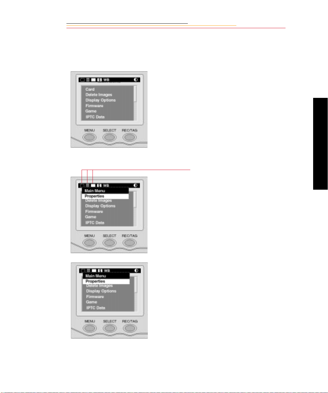
Menu Bar
To provide more room on the Image Display screens, the Menu bar is only displayed at
your request. When you turn the Image Display On, the last screen used appears without
the Menu bar. If you then press the MENU button, the Menu bar appears.
☛ Shortcut, press an d hold the MENU button to turn the I m age Dis pl ay On and di spl ay
the Menu bar.
The original Menu bar looked like this:
The new one looks like this:
When the Menu bar is displayed, the contrast of the remainder of the screen is lowered,
giving it a “grayed-out” appearance.
2
Page 6
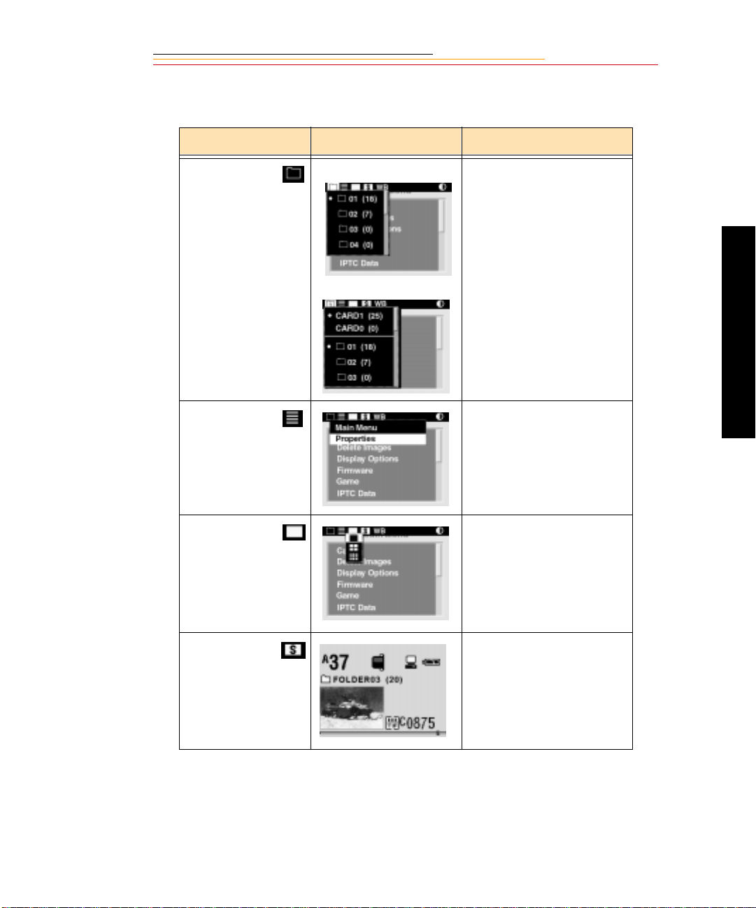
When you select t he f ol lowing icons on t h e Men u bar, the se dropdown menus and s creens
appear:
Icon Dropdown Menu Function
Folder icon One PC Card:
Two PC Cards (p age 7):
Menu icon Displays choices for the
Display icon Displays choices for Single,
Displays the Folder menu.
(Refer to chapter 4 of the
User’s Manual.)
Main and Properties menus.
Four, and Nine Image
Review mode. (Refer to
chapter 9 of the User’s
Manual.)
New Features
Status icon Displays the Status screen
that contains information
about the current image.
3
Page 7
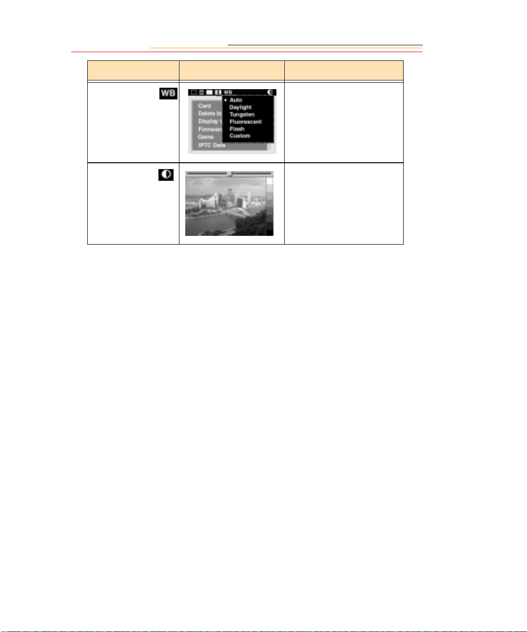
Icon Dropdown Menu Function
White
Balance icon
Contrast icon Displays the Contrast screen
Displays choices for White
Balance settings (page 18).
where you can adjust the
contrast of the images
displayed on the Image LCD
panel. (The images
themselves are not affected.)
4
Page 8
Navigating the Image Display
Use the following guidelines when navigating the Image Display
Display the Menu bar and selec t a
Menu bar icon
Press and hold the MENU button
and rotate the Main Command dial
until the desired icon is highlighted.
Display a Dropdown menu
Highlight the Folder, Menu,
Display, or White Bala nce icon , and
continue pres sing the MENU button
until the dropdown menu appears.
New Features
Choose an item from a dropdown
menu
When a dropdown menu appears,
continue to press the MENU button
and rotate the Main Command dial
until the desired menu choice is
highlighted.
5
Page 9
Chose an item from a menu
screen
Press and hold the SELECT button
and rotate the Main Command dial
to highlight your choice.
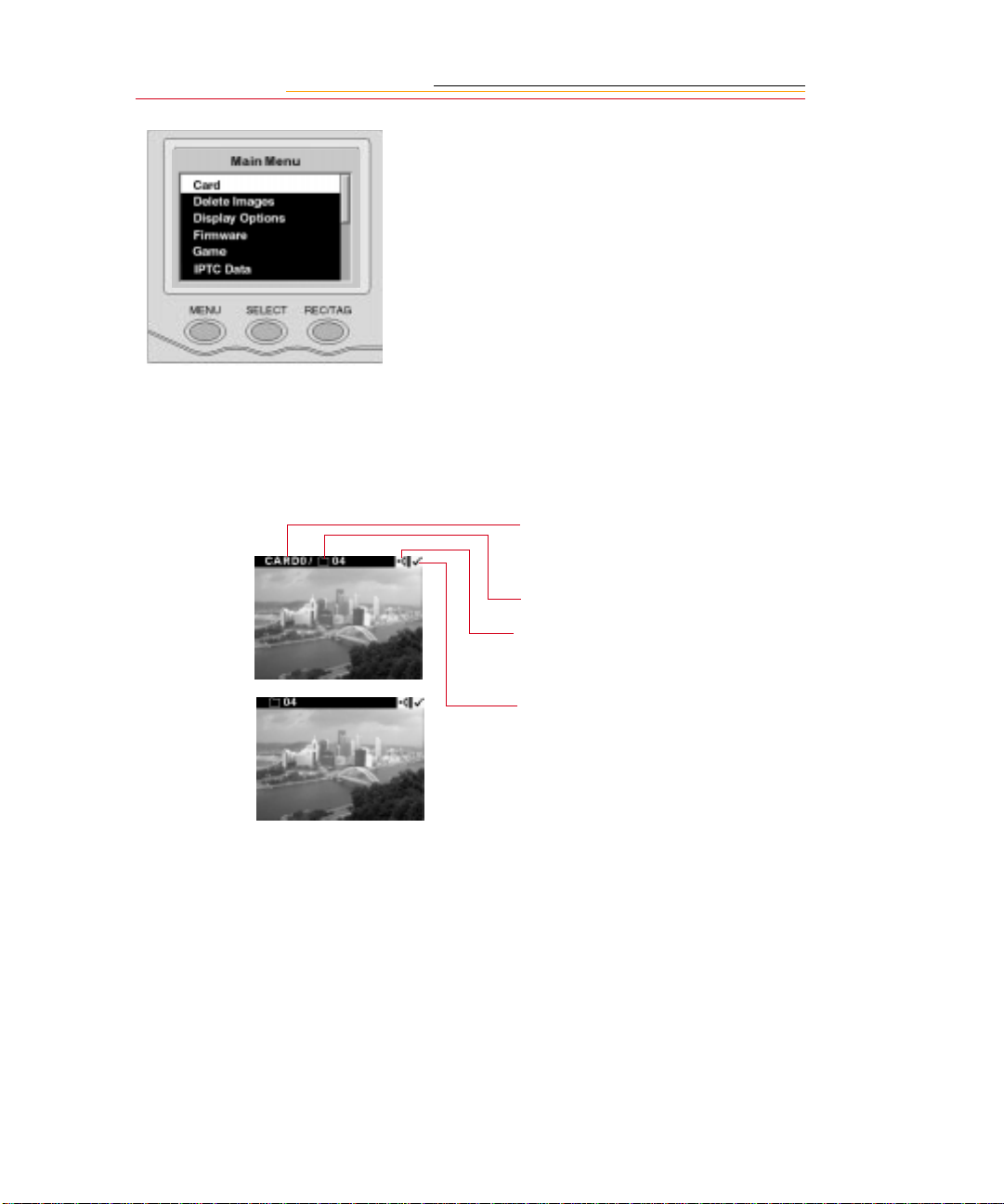
Status Bar
A Status bar appears whenever images are displayed (in Single, Four, or Nine Image
Review mode). Information about the currently selected image appears on the Status bar:
✔ The currently act ive PC Card
(if there are two cards in the
camera)
Two PC Cards
One PC Card
✔ The currently active folder
✔ Sound icon (if one or more
sound files are associated
with the selected image)
✔ Tag icon (if the selected
image has been tagged)
☛ Refer t o chapter 9 of the
User’s Manual for informat ion
on tagging or associating a
sound file with an image.
6
Page 10
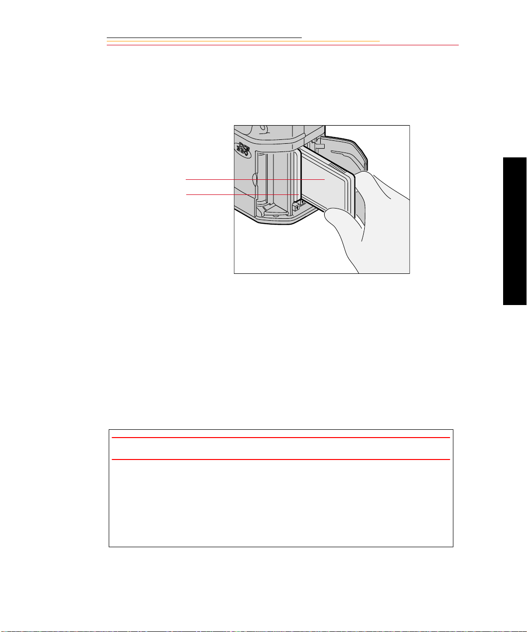
Dual Slots for PC Cards
The second PC Card slot has been enabled on the DCS 330 camera. With Type II PC
Cards, you can use one or both slots. With Type III PC Cards, only one slot can be used.
The card in the rear slot is referred to as CARD0, and the card in the front slot as CARD1.
CARD0
CARD1
Insert PC Cards as descr ib ed in cha pter 4 o f the Use r’ s Manual. When using one PC Card ,
you can use either slot. When using two cards, the first card inserted will be the active
card. When you capture or delete images, they will be saved to or deleted from the active
card.
New Features
With two PC Cards inserted, the following procedures are slightly different than those
described in the User’s Manual. (With one card, refer to chapter 4 of the User’s Manual.)
✔ Selecting a PC Card or folder (page 8)
✔ Deleting images (page 9)
✔ Formatting a PC Card (page 10)
IMPORTANT:
✔ Your camer a us es 3 volt or 5 vo lt PC Cards. Wh en y ou u se t w o c ards, they mu s t
both have the same voltage rating. If you insert two cards with different
voltages, neit her i s power e d. A “Ca r d Voltage Mix” message app ears. You need
to remove one of the cards so that the other can be powered.
✔ After inserting one PC Card, wait for the PC Card Busy/Record LED to stop
blinking before inserting the second card. Failure to do so will cause an error.
7
Page 11
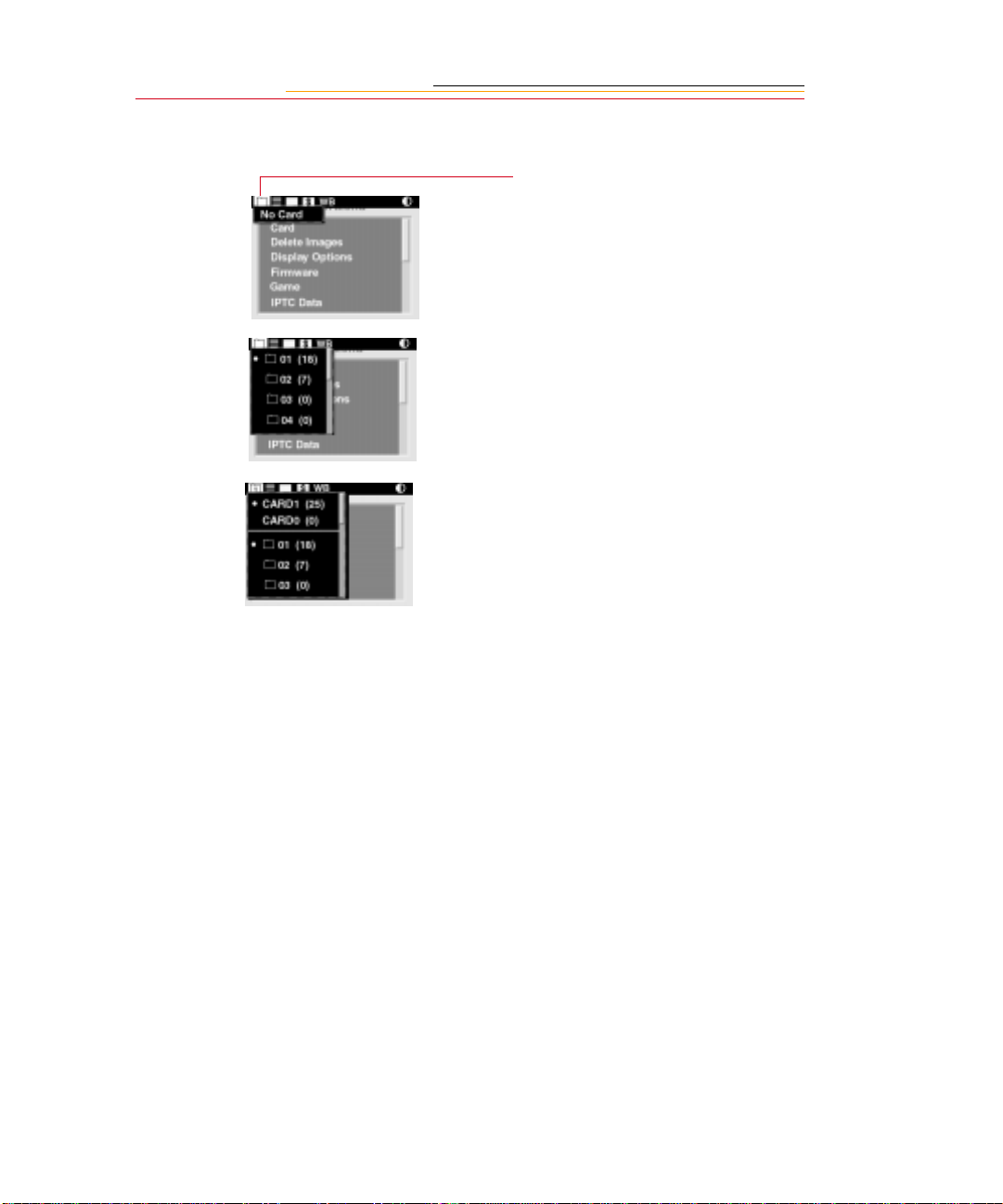
Selecting a PC Card or Folder
x
1
Select the Folder icon (page 5).
If there is no PC Card in the
camera, an X appea rs w i thi n the
Folder icon. Selecting the Folder
icon produces the screen at the
left.
With one PC Card inserted, this
dropdown menu appe ars with a •
displayed next to the currently
active folder.
With t wo PC Cards ins erted, this
dropdown menu appe ars with a •
displayed next to the currently
active card and the currently
active folder on that card.
A 0 or 1 appears in the Folder
icon, indicating the active PC
Card.
The listed folders are on the
active card. The fold er li st
changes when you change cards.
The numbers in par entheses next
to the cards and folders indicate
the number of images in each.
2 Continue pressing the
MENU button.
3 With two PC C ards inserted,
select CARD0 or CARD1 from
the dropdown menu (page 5),
then select a folder. With one
card inserted, select a folder.
8
Page 12
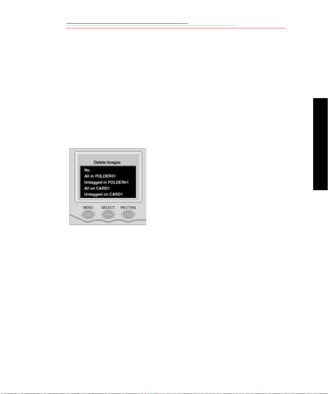
Deleting Imag es
To delete images when one card is inserted, display the Main menu (page 5), then delete
images as described in chapter 9 of the User’s Manual. If two cards are inserted, do the
following:
1 Select a different PC Card, if
necessary (page 8).
2 Select the Menu icon, t hen
choose Main Menu from the
dropdown menu (page 5).
The Main menu appears.
3 Select Delete Images.
The Delete Images screen
appears, displaying choices for
the act ive PC Card.
4 Press and hold the SELECT
button and rotate the Main
Command dial to highli ght your
choice.
New Features
9
Page 13
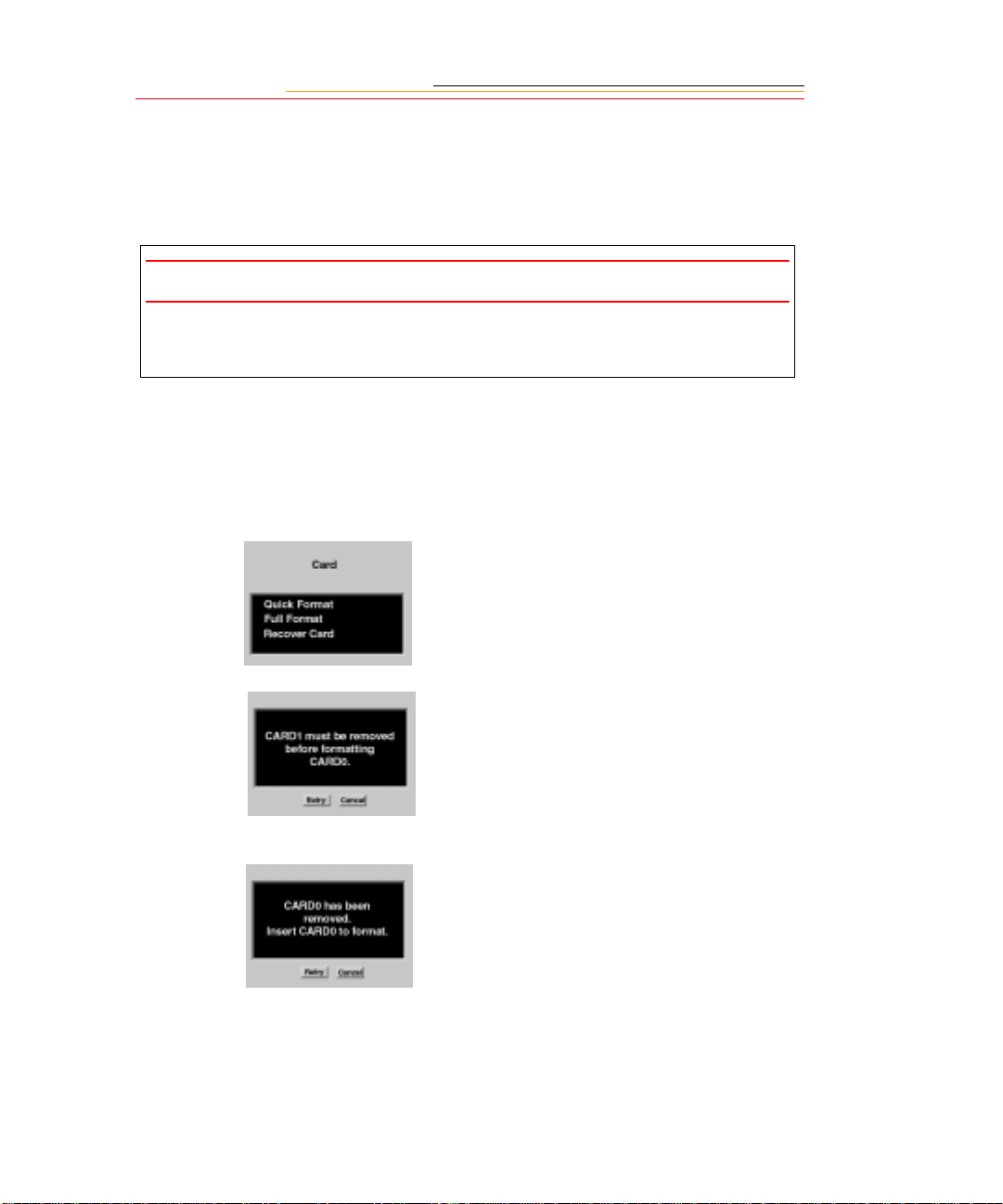
Formatting a PC Card
There can only be one PC Card in the camera when you format a card. This is a safety
feature to preve nt f ormatting the wrong ca rd. You can format a card using ei ther th e Quick
Format or the Full Format feature.
IMPORTANT:
Quick format, while fa st er, is not r eco mme nde d if th ere i s a poss ib il it y th at th e dat a on
the card is corrupted.
1 Select the Menu icon, th en
choose Main Menu (page 5).
2 Select Card from the Main
menu.
The Card menu appears.
3 Choose Quick Format or Full
Format.
10
If two cards are in the camera,
you are prompted to remove the
inactive card. For example, if
CARD0 is active, you are
prompted to remove CARD1.
Remove the inactive card, then
select Retry.
If you remove the active card,
the message at the left appears:
Re-insert the card in the proper
slot, then select Retry.
4 Proceed with formatting as
described in chapter 4 of the
User’s Manual.
Page 14

JPEG File Pr o cessing
The DCS 330 camer a su ppor ts background image pr oc essing that produce s JPEG or TIFF
RGB files that can be opened directly by any image editing software.
The choices for processed files are JPEG Good, Better, Best, and TIFF RGB. JPEG Good
files have th e m os t com pr ession, J PEG Be st have the least —the less compres si on applied,
the better the image quality in the processed file and the larger the file size. The final
JPEG file size varies, depending on image content. TIFF RGB files are not compressed.
When you capt ure images, the y a re w r it t en t o t he s el ect ed folder on the PC Card using t he
TIFF Custom format, regardless of whether Processing is turned on. If you turn on
Processing, JPEG Best, Better, Good, or TIFF RGB files are created in the background
(when the camera is not busy with other tasks such as capturing images).
JPEG files are saved to a JPEG folder and TIFF RGB files are saved to a TIFF RGB
folder. These folders are created on the PC Card when you turn on Processing (if they are
not already there). If you select the JPEG or TIFF RGB folder to review images, then
capture an image, a message informs you that images cannot be saved in that folder. The
images are saved in the default folder established in Properties. (Refer to chapter 3 of the
User’s Manual.)
The default for Processing is Off. When you turn on Processing, it stays on until you turn
it off, or remove the PC Card.
Processing with Two PC Cards
When you have PC Cards insert ed i n bot h slots (page 7), im ag es are process ed on t he card
that is active when you turn on Processing. If you make the other card active, processing
continues on the card originally designated for processing. For example, if CARD0 is
active when you t ur n on Pr oce ssi ng, then you change t o CARD1, processing cont inu es on
CARD0, but not on CARD1. In this case, if you want to switch Processing to CARD1,
you must turn off Processing, then turn it back on. When turned on, Processing is
automatically set for the active card (CARD1).
New Features
11
Page 15

Processing Images
1
Select the Menu icon, th en
choose Main Menu from the
dropdown menu (page 5).
2 Select Processi ng from the Main
menu.
The Processing screen appears.
With two cards, the active card
is indicated (e.g. CARD1).
3 Press and hold the SELECT
button and rotate the Main
Command dial to select your
choice.
Choice Images Processed
OFF Turns off Processing
Tagged
in folder
All in
Folder
Tagged
Images
All on
Card
Change
Settings
All tagged images in
the selected folder on
the acti ve card
All images in the
selected folder on the
active card
All tagged images on
the acti ve card
All images on the
active card
Displays a screen
where you can change
Processing setti ngs
(page 15)
12
The Processing confirmation
screen appears.
4 Select OK to begin processing
or Cancel to return to the M ain
Menu without processing.
Page 16

Processing Messages
When you enable Processing, the screens in the table below may appear.
Condition Screen Your Action
There i s no PC Card inserted in
the camera.
Processing is enab le d for the
selected folder and there are no
images in the folder.
Similar screens appear when the
same condition exists for Tagged
images or for All Images On The
Card.
Processing is enab le d for the
selected folder and all images in
the folder have been processed.
Similar screens appear when the
same condition exists for Tagged
images or for All Images On The
Card.
There are two PC Card s inserted
in the camera. With processing
enabled for one card, you make
the other card active, and access
the Processing menu.
Click OK and insert a
PC Card.
New Features
If you click OK, new
images are processed
when you capture them
to that folder.
If processing is enabled
for tagged images or all
images on the card,
images are processed as
you tag or capture them.
If you click Cancel,
Processing is not started.
If you click OK,
Processing continues on
the inactive car d.
If you click Cancel,
Processing stops on the
inactive card. You can
then enable Processing
on the active card, if
desired.
13
Page 17

Condition Screen Your Action
Your processing settin gs a re s et to
delete the original TIFF image
(page 15) when you process files.
The active PC Card becomes full
as images are being processed.
This can occur regard les s of
whether there are one or two cards
in the camera.
Y ou re move a PC Card at an y time
while Processing is enabled
(whether or not images are
currently being processed).
If you click OK, a
second confirmation
screen appears.
If you click Cancel,
Processing is n ot start ed.
The Processing menu
appears.
Click OK and insert a
new card or make the
second card active.
14
Page 18

Changing Processin g Set ti ngs
There are several processing settings that you can change. The settings are applied to
images as they are processed.
1 Select Change Settings (page
12).
The Processing Settings screen
appears with the current values
shown in parentheses.
2 Select the desired setting.
The following screens appear,
depending on your choice:
New Features
Processing
Settings
Original
TIFF
File Type JPEG Best
Screen
Choices
(Defaults
Underlined)
Save
Delete Deletes the Custom TIFF
Better, Good,
TIFF RGB
Result
Saves the Custom TIFF
image (default)
image after the processed
JPEG or TIFF RGB file has
been saved.
,
Files are processed to the
selected JPEG quality or to
TIFF RGB.
15
Page 19

Processing
Settings
Screen
Choices
(Defaults
Underlined)
Result
Resolution 100%
Maintains the size and spat ial
resolution of the original
image.
67% The dimensions of the
resulting images are reduced
by 2/3. T he spatial resolution
of the resulting image is
about 1/2 of the original.
50% The dimensions of the
resulting images are reduced
by 1/2. T he spatial resolution
of the resulting image is
about 1/4 of the original
Noise
Reduction
Yes
Noise is reduce d in proces sed
images.
No Noise is not reduced.
Look Portrait Applies a lower contrast tone
scale with more detail in the
highlights and shadows.
Product
Applies a higher contrast,
more vibrant tone scale.
Sharpening
Level *
None
No sharpening is applied to
the finished image .
High Progressiv ely less shar penin g
Medium
Low
is applied to the finished
image.
* The Sharpening Level setting in the Processing menu determines whether sharpening is
applied when images are processed on the camera. The Sharpening property in the
Properties menu determines whether sharpening is applied by the DCS Host software.
16
Page 20

Working with TIFF Cust om Files on your Computer
If you don’ t pro cess i mages on your camera , you nee d to us e one of the f ollo wing softwa re
applications to work with the TIFF Custom files. (The TIFF Custom file format is
proprietary to KODAK.)
File Format Module (New product)
✔ This software appl ic ati on all ows yo u to op en hi gh re sol ut io n TIFF Custom images
directly into Adobe Photoshop.
DCS Acquire Module or DCS TWAIN Data Source
✔ These are full-featured image editing and acquire software applications.
If the DCS Host Software CD (included with your camera) includes the DCS Acquire
Module and DCS TWAIN Data Source version 5.8 or later, you are given the option of
inserting the File Format Module. If the CD includes a version prior to 5.8, the DCS File
Format Module is not included. To download the DCS File Format Module, visit the
Kodak Web site (www.kodak.com).
The DCS Acquire Module and DCS TWAIN Data Source allow you to make
enhancements specific to images from your camera, and generally provide the best image
quality. When such enhancements are not necessary, the DCS File Format Module
provides a fast way to open images in Adobe Photoshop where you can perform other
enhancements, if needed.
☛ If you attempt to open TIFF Custom files in Adobe Photoshop without using the
DCS File Format Module, the DCS Acquire Module, or DCS TWAIN Data Source,
only the thumbnail version is available, with a less than optimal image resolution.
New Features
17
Page 21

White Balance
The DCS 330 camera provides preset and custom White Balance functionality where you
can identify the type of lighting used to capture images.
Preset White Balance options are built into the firmware. They include Auto, Daylight,
Tungsten, Fluorescent, and Flash. You choose the preset option that is closest to the
lighting conditions present when you capture images. For example, if you capture images
in daylight, you would select Daylight for the best results. The Auto setting uses a
proprietary Eastman Kodak Company image science algorithm to calculate and then
adjust the image’s white balance as well as adjust the image’s exposure.
With the Custom setting, you provide a calibration image or save White Balance settings
using the DCS Acquire Module or DCS TWAIN Data Source (version 5.8 or later). You
then load the settings into the camera where you can select and reuse them. You can also
delete White Balance settings when they are no longer needed.
This ability to save and reuse White Balance settings saves you time if you repetitively
work under the s ame lig hting c ondit ions. For exampl e, if you frequ ently wo rk in an indoor
stadium with a parti cul ar type of lighting, yo u can na me and s ave a Whi te Balan ce se tt ing
for reuse.
Selecting White Balance
You can select a preset White Balance option (Auto, Daylight, Tungsten, Fluorescent, or
Flash) or Custom White Balance. If you select a preset option, that White Balance setting
is applied to images that you capture. If you select Custom, other options become
available, as described on the next few pages.
18
1 Select the White Balance icon
(page 5).
The White Balance dropdown
menu appears.
2 Select Auto, Daylig ht, Tungste n,
Fluorescent, Flash, or Custom
Page 22

Using Custom White Balance Settings
Once you have selected Custom White Balance, you can access several Custom White
Balance options.
1 Select Custom White Bala nce as
described above.
If there are no images in the
selected folder, the screen at the
left appears.
If the selected folder contains
images, this screen appears,
showing the currently selected
image.
New Features
19
2 Press and hold the SELECT
button and rotate the Main
Command dial to select your
choice:
OK—The White Balance values
from the selected image are
saved using the same name as
the image. The se ttin g is appli ed
to subsequent images that you
capture. ( T hi s set ti ng overwrites
the sett ing that was saved the
last time you chose OK.)
Cancel—The White Balance
setting does not change.
Page 23

Options—The White Balance
Settings menu appears. You can:
✔ Select a White Balance
setting from the selected
image or from those loaded
on the camera (page 21)
✔ Delete a White Balance
setting from the camera
(page 21)
✔ Load a W hite Balance
setting fr om a PC Ca rd t o the
camera (page 22)
✔ Save a White Balanc e setting
(page 24)
20
Page 24

Selecting Custom White Balance Settings
With the White Balance Settings menu displayed (page 20), choose one of the following:
Image #nnnn: The White Balance values from the selected image are applied to
images that you capture.
Previously loaded setting—The White Balance values from the previously loaded
setting (page 22) are applied to images that you capture.
Deleting Custom White Balance Settings
You can delete White Balance Settings that have been loaded on your camera.
1 With the White Balance Settings
screen displayed (page 20),
choose D elete WB Settings.
The Delete White Balance
Setting menu appears.
2 Press and hold the SELECT
button and rotate the Main
Command dial to choose the
setting to be deleted.
3 Release the SELECT button.
New Features
21
A confirmation screen appears.
4 Select Yes to delete the setting,
or No to leave it intact.
Page 25

Loading Custom White Balance Settings
Once you have saved White Balance settings to a PC Card, you can load them into your
camera. There are a few rules to remember when you do so.
Rule Error Message
You can only load settings into the camera used to
capture the images.
Each setting that you load must have a unique name.
Your camera holds up to ten Custom White Balance
settings.
22
Page 26

1 With the White Balance Setting
screen displayed (page 20),
choose Load from Card.
The Load White Ba lance S etting
screen appears with a list of the
White Balance settings on the
active PC Card. (If only one
card is in the camera, the card
choices do not appear.)
2 Press and hold the SELECT
button and rotate the Main
Command dial to choose the
desired card. (You may need to
scroll up to the card choices if
there are numerous White
Balance settings.)
3 Repeat step 2 to choose the
desired Custom White Balance
setting.
The setting is loaded from the
PC Card to your camera, and
appears in the list of settings.
New Features
23
☛ When you load se ttin gs from a
PC Card , the last settin g
loaded is the active White
Balance setting.
Page 27

Saving White Balance Settings using your Camera
Y ou can sa ve the cu rrent camera- genera ted White Bala nce setti ngs, then appl y the set ting s
to subsequently captured images.
1 Capture an image with a neutral
area (such as a gray or white
card) in the center.
2 With the White Balance Setting
screen displayed (page 20),
choose Save (Image nnnn).
A confirmation screen appears.
3 Select Yes to save the setting or
No to return to the White
Balance Settings menu without
saving.
If you save t he setti ng, it appears
on the White Balance Settings
and the D elete White Balance
Settings screens.
Saving White Balance Settings using the Computer
You can als o sa ve W hit e Ba la nce settings to a P C Card u si ng t he DCS Acquire Module or
DCS TWAIN Data Source, then load the settings in your camera.
1 Capture an image with a neutral area (such as a gray or white card) in the center.
2 Using the DCS Acquire Modul e or DCS TWAIN Data Source, save the Whit e Balance
setting to a PC Card. (Refer to the KODAK PROFESSIONAL DCS Host Software
User’s Manual.)
☛ When you save a White Balance setting to a PC Card, a “.wb” extension is added to
the file name. For example, if you save the setting from a file named A0601385.TIF,
the setting will be named A0601385.wb on the PC Card.
3 On your camera, select White Balance (page 18).
4 Load the White Balance setting from the PC Card to your camera (page 22).
5 Select the desired White Balance setting (page 21).
24
Page 28

Intervalometer
Your camera has an Intervalometer that you can set so that a sequence of images are
captured automatically at specified intervals over a specified period of time. You might,
for example, use the Intervalometer to capture the different stages of a flower bud
opening. You can set the following:
✔ Number of frames to be captured
✔ Interval between exposures
✔ Delay before the timer begins
✔ Enable or disable the Intervalometer
The Intervalometer is disabled automatically after the specified time has elapsed, even if
the specified number of images have not been captured. For example, if you set the
Intervalometer for fifteen exposures at one second intervals, the camera would only
capture images until the buffer is full, even if fifteen images had not been captured.
☛ While the Interva lomete r is enabled, th e camera ma y enter PowerSa ve mode phase 1.
This depends on the interval between exposures. The camera may also enter
PowerSave mode phase 2, depending on the Display Off Time and Display Off
Using Adapter Property settings. (Refer to chapter 3 of the User’s Manual.) The
camera will not enter PowerSave mode Phase 3 if the Intervalometer is enabled.
(Refer to chapter 2 of the User’s Manual.)
New Features
25
1 Select the Menu icon, t hen
choose Main Menu (page 5).
The Main menu appears.
2 Choose Intervalometer from the
Main menu.
The Intervalometer screen
appears.
3 Press and hold the SELECT
button and rotate the Main
Command dial to choose the
desired setting.
Page 29

Your choices on the Intervalometer screen cause the following screens to appear:
Intervalometer
Settings
Timer Count
Timer Interv al
Timer De lay
Timer En able
Screen Your Action Result
Set the timer
count—1-9999
frames
Default: 10 frames
Set the timer
interval— 1 second
to 23:59:59
(HH:MM:SS)
Default: 10
seconds
Set the timer
delay—1 second
to 23:59:59
(HH:MM:SS)
Default: 1 second
Select Yes
Select No
Default: No
Specifies the
number of fram es to
be captured
Specifies the
interval bet w een
image captures
Specifies the delay
before onset of the
Intervalometer
function
Enables the
Intervalometer
function
Disables the
Intervalometer
function
☛ To change settings in these screens, use the same technique described for setting
Display Off Time. Refer to chapter 3 of the User’s Manual.
26
Page 30

Recovering Deleted Images
You can recover images that were previously deleted from a PC Card, if they have not
been overwritten. Only images that were written to a PC Card by a DCS 330 camera can
be recovered.
☛ For the Recover function to work, the PC Card must have been formatted on the
camera. (The Recove r funct ion wil l not wor k for a ca rd “out of the bo x” or for mat ted
using the DCS Host software.)
1 Select the Menu icon, t hen
choose Main Menu (page 5).
2 Select Card from the Main
menu.
3 Select Recover Card from the
Card menu.
This screen app ear s. (A Rec over
folder is created on the PC Card
when you recover images.)
☛ You cannot capture images to
the Recover folder. If you
attempt to do so, the image is
saved to the default folder (set
in Properties) and an
appropriate message appears.
This screen appears while
images are being recovered.
When the recovery process is
complete, this scr een appear s,
telling you how many files were
recovered.
New Features
27
Page 31

Name Plate
Using the DCS Acquire Module or DCS TWAIN Data Source, you can enter text that
appears in certain screens on your camera. The Name Plate is useful for personalizing
your camera, for example, “This camera belongs to Joe Smith”.
In the DCS Acquire Module or DCS TWAIN Data Source:
1 Click the Camera Control button.
The Camera Control dialog box appears.
2 Click the Properties button.
The Properties dialog box appears.
3 Scroll through the list and select the Name Plate property.
4 Enter up to 50 characters of text in the Name Plate text box.
The text appears in the following screens on the camera’s Image LCD panel:
✔ No images in folder
✔ No images in memory
✔ No card in camera
28
Page 32

Global Positioning System
Your camera has an option for a Global Positioning System (GPS), which uses satellite
information to determine the latitude and longitude location of the camera. This
information, along with the time and date, is saved with the image. You can view it using
the DCS Acquire Module or DCS TWAIN Data Source.
1 Insert a T rimble Path finder Type
II GPS PC Card in slot 0.
2 Select CARD1 (page 8).
The card must go in slot 0. If
you insert it in slot 1, an error
message appears. (I nse rt the
card in slot 0 and select Retry.)
3 Select the Menu icon, t hen
choose Main Menu from the
dropdown menu (page 5).
The Main menu appears. When
the Trimble Pathfinder card is
properly inserted, a GPS choice
appears on the menu.
4 Select GPS.
This screen updates during the
GPS acquisition process. The
number of satelli te s inc re ases as
signals are received. The
process may take up to 1.5
minutes.
When the acquisition process is
complete, a screen like this
appears.
If the GPS status is Good
Position, the location has been
determined and is saved with
subsequently captured images.
The table below lists messages
that may appear during the
acquisition process:
New Features
29
Page 33

Message Cause Remedy
Unknown. There is an undetermined
problem with the GPS card.
PDOP too high. The GPS measure of error
(PDOP) is too high.
No GPS Time. The GPS is not receiving any
signal from any satellite.
No satellites. There is not a viable signal from
any satellite.
1, 2, or 3 satellites. The GPS requires a constellation
of 4 satellites. The sat ellite
constellation is not complete.
Insert a different GPS card, reinsert the card or try again later.
Insert a different GPS card, reinsert the card or try again later.
Try again later.
Try again later.
Try again later.
☛ If any of these condi tions persis t for more th an 1 1/2 minu tes, the satell ite si gna ls are
being blocked by a n ob ject such as a t re e or a b u il di ng. Ch ange your location a nd t ry
again.
30
Page 34

IPTC Data Management
This feature allows inclusion of International Press Telecommunication Council (IPTC)
data as part of the image hea der. You enter t he IPTC data on your computer using the DCS
Acquire Module or DCS TWAIN Data Source (version 5.8 or later) and save it to a PC
Card. (Refer to the KODAK PROFESSIONAL DCS Host Software User’s Manual.)
Once the data has been saved to a PC Card, you can load it into your camera (page 32).
You may
1 Select the Menu icon, t hen
choose IPTC Data from the
dropdown menu (page 5).
The IPTC Data menu appears.
2 Press and hold the SELECT
button and rotate the Main
Command dial to select your
choice:
None—No IPTC data will be
written to the image headers.
IPTC data file—If there is an
IP TC file in the camer a, its name
is displayed. Choosing this
option writes the IPTC data to
the image header.
Load from Card—You can
load an IPTC file from a PC
Card (page 32).
New Features
31
Page 35

Loading IPTC Data from a PC Card
1
With the IPTC Data screen
displayed (page 31), choose
Load from Card.
The Load IPTC Data screen
appears with a list of the IPTC
files on the active PC Card. (If
only one card is in the camera,
the card choices do not appear.)
2 Press and hold the SELECT
button and rotate the Main
Command dial to choose the
desired card. (You may need to
scroll up to the card choices if
there are numerous IPTC files.)
3 Repeat step 2 to choose an IP TC
file.
The file is loaded from the PC
Card to your camera, and
subsequently appears in the list
of IPTC data files.
Each file must have a unique
name. If you attempt to load a
file with the same name as a file
on your camera, a message will
ask if you want to replace the
existing file.
32
Page 36

Sharpening
Your DCS 330 camera is equipped with an antialiasing filter, an optical filter that is
mounted inside the camera in front of the electronic imager. This filter improves overall
image quality at the expe nse of a small loss of shar pne ss in t h e i mage . Depe ndi ng on y our
subject, you may or may not want to add sharpening. For example, you might want to
sharpen an image of a piece of equipment and might not want to sharpen a portrait. There
might also be instances where you would want to remove the antialiasing filter.
When you use the DCS Acquire Module or DCS TWAIN Data Source with your DCS 330
camera, you can specify whether or not you want the image sharpened.
The antialiasing filter uses optical design to reduce or eliminate the high frequency image
patterning problems associated with single-shot digital capture and interpolation. The
optical effect causes a small change in how lenses perform compared to cameras without
the filter installed.
If you choose to use manual focus, be advi se d that some zoom lense s experience a shi ft in
the focus point as the focal length of the zoom is changed. If you zoom into your subject
matter for close focus then zoom out to compose your image, the focus point changes.
This is easily remedied by only focusing at the zoom setting that you use to capture the
image.
New Features
33
Page 37

In the Camera
You can set a camera property that tells the DCS Acquire Module or DCS TWAIN Data
Source whether the antialiasing filter was installed or removed when an image was
captured.
The default setting is “Installed”. If you remove the antialiasing filter, you need to set the
property to ”Removed”. Refer to chapter 11 of the User’s Manual for instructions on
installing and removing the antialiasing filter.
1 Choose Properti es fr om the
Main menu. Refer to chapter 3
of the User’s Manual for
instructions.
The Properties menu appears.
2 Chose Antialiasing Filter from
the Properties menu.
The Antialiasing Filter screen
appears.
3 Choose either Installed or
Removed, depending on
whether the antialiasi ng filter is
currently installed.
34
Page 38

In the DCS Acquire Module or DCS TWAIN Data Source
You can set a preference in the DCS Acquire Module or DCS TWAIN Data Source that
determines whether the sharpening feature is applied to images acquired from your DCS
330 camera. The choices for this preference are:
At Capture (default setting)—Images are sharpened if the camera’s Antialiasing
✔
Filter property was set to Installed.
On—Images are always sharpened.
✔
Off—Images are never sharpened.
✔
1 Start the DCS Acquire Module
or DCS TWAIN Data Source.
Refer t o the Readme or the
KODAK PROFESSIONAL
DCS Host Software User’s
Manual on the CD inc luded with
your camera.
2 Click the Preferences Icon.
The Preferences dialog box
appears.
New Features
35
3 Choose At Capture, On, or Off
from the Sharpen Images list
box.
4 Choose High, Medium, or Low
from the Level list box—(the
higher the level, the more
Sharpening).
Page 39

The following table shows whether Sharpening is applied or not applied, depending on
settings in the camera’s Antialiasing Filter property and the software’s Sharpen Images
preference:
C a m e r a P r o p ert ie s :
Antialiasing Filter
DCS Acquire Module or DCS TWAIN Data Source
Preferences: Sharpen Images
At Capture On Off
Installed Applied Applied Not applied
Removed Not applied Applied Not appl ied
36
Page 40

Serial Port Operation
You can us e t he serial port o n your camera to t r ansf er da ta between your c amer a and other
devices. There is a new KODAK product that enables you to transmit images to a remote
location using a cellular phone.
Connecting a Device to the Serial Port
Y ou can connec t a varie ty of d evice s to you r c amera’s serial port usi ng a se rial cable tha t is
available from your dealer of KODAK products. Devices used to transmit text strings
must be RS-232 compliant.
1 On your camera, remove the
SELECT
MENU
Ps
MDE
FNC
SET
( ) +/-
REC/TAG
RESET
protective serial port cap, then
plug the appropriate end of the
serial cable into the serial port.
2 Connect the other end of the
cable to your RS- 232 compl iant
device.
BUSY
New Features
37
Page 41

Accessing Serial Port Options
1 Select the Menu icon, th en
choose Main Menu from the
dropdown menu (page 5).
2 Select Seria l Port fro m the Main
menu.
The Serial Port menu appears.
3 Select one of the following:
✔ Baud Rate (page 38)
✔ Serial In (page 39)
✔ Serial Out (page 41)
Setting the Baud Rate
Before transmitting data between the camera and a connected device, you must set the
baud rate required by the device. Choose from 300, 600, 1200, 2400, 4800, 9600, 19200,
38400, 57600, and 115200.
1 Select Baud Rate f rom the Serial
Port menu (page 38).
The Baud Rate menu appears.
38
2 Select the appropriate baud rate
for the connected device.
The setting is retained until you
change it.
Page 42

Serial In Mode
When the serial port is in Serial In mode, your camera accepts text strings from a
connected external device. The information is then added to specified image headers.
1 Select Serial In from the Serial
Port menu (page 38).
The Serial In Mode menu
appears.
2 Select your choice (described in
the table below).
The setting is retained until you
change it, disco nnec t the de vice,
or use th e Transmit option ( page
42). Modem is selected
automa tically with this option.
Menu
Choice
None No data received Serial port is unavailable.
New Images The text string from the
connected device is written to
the header of subsequent
images.
Previous
Image
GPS A text strin g f rom the connecte d
Remote
Release
Modem Reserved for Transmit option
A text string from the connec te d
device is written to the header of
previously captured image file.
GPS dev ice is written to the
header of the just-captured
image file.
An image is captured when you
activate the connected remote
cable release.
(page 42)
Action Comments
Text string must be 250 valid
characters, or less. Valid characters
consist of ASCII characters, carriage
return, and line termination.
When you select New Images or
Previous Image, a Serial In Status
option (page 40) becomes available.
If a Trimble GPS card is inserted in the
camera (page 29), the serial port GPS
functionality is over-ridden by the
Trimble card.
Use the remote release to minimize
camera movement or when you are
away from the camera. Contact your
service representative regarding a
cable, if needed.
Set automatically when you use the
Transmit opt ion .
New Features
39
Page 43

Serial In Status
When you select New Im ages or Pr evious Image from th e Seria l In Mode menu, th e Serial
In Status choice becomes available.
Select Serial in Status from the
Serial Port menu.
If the connected device is sending
data, a message indicates the most
recent data rece ive d.
If there is no device connected or if
a connected device is not currently
sending data, this message appears.
40
Page 44

Serial Out Mode
When the serial port is in Serial Out mode, your camera sends data to a remotely
connected device.
1 Select Serial Out from th e Seria l
Port menu (page 38).
The Serial Out Mode menu
appears.
2 Select your choice (described in
the table below).
The setting is retained until you
change it, or use the Transmit
option (page 42). Modem is
selected automatically with this
option.
Menu Choice Action Comments
None No data transmitted
Image Number A text str in g con tai ning the image
number of th e ju st-ca pture d image
is sent to the connected device.
Modem Reserved for Transmit option
(page 42)
Remote Release Remote Release is automatically
selected when you select Remote
Release in the Serial In menu.
Contact your service
representa tive regarding a cabl e, if
needed.
Sync Pulse A +3VDC signal with a duration
identical to the exposure duration
is sent to the connected device.
New Features
41
Page 45

Image Transmit
You can transmit images from your camera to a remote computer using a cell phone or
modem. The DCS Transmission kit (available from your dealer of KODAK products)
includes hardware and documentation. It also contains a certificate with information that
you must use to acquire a special firmware key.When you load firmware version 3.2 or
later into your camera, you can activate the Transmit option by loading the firmware key.
42
Page 46

2
EASTMAN KODAK COMPANY
Rochester, New York 14650
© Eastman Kodak Company, 2000
Kodak and Kodak Professional are trademarks.
P/N 6B4723
 Loading...