

Knight Equipment OP Installation Manual
MF & OP SIGNAL FILTER
(MANUAL ADDENDUM)
OVERVIEW
The purpose of this addendum is to inform you of a low voltage signal filtering feature on the Multi-Flow and OnPremise dispensing systems that is not covered in the instruction manual you have. All other functions of these
systems will remain the same.
The signal filtering capability can help prevent unwanted injections caused by stray signals or “bleed“ voltages.
Typically you will have only one signal common, however, if using “split commons”, each common can be
independently set to filter signals.
OPERATION
The signal filter is activated by removing a jumper wire on the pump circuit board. There is one jumper wire for
common A and one for common B (if required). See the diagram below for location of the jumper wires.
• When the jumper wire is removed, the signal input range is 70 – 240 volts.
• With the jumper wire in place (normal) the signal input range is 24 – 240 volts.
• Do not connect any signal wires or common wires to the terminals where the jumper wires go.
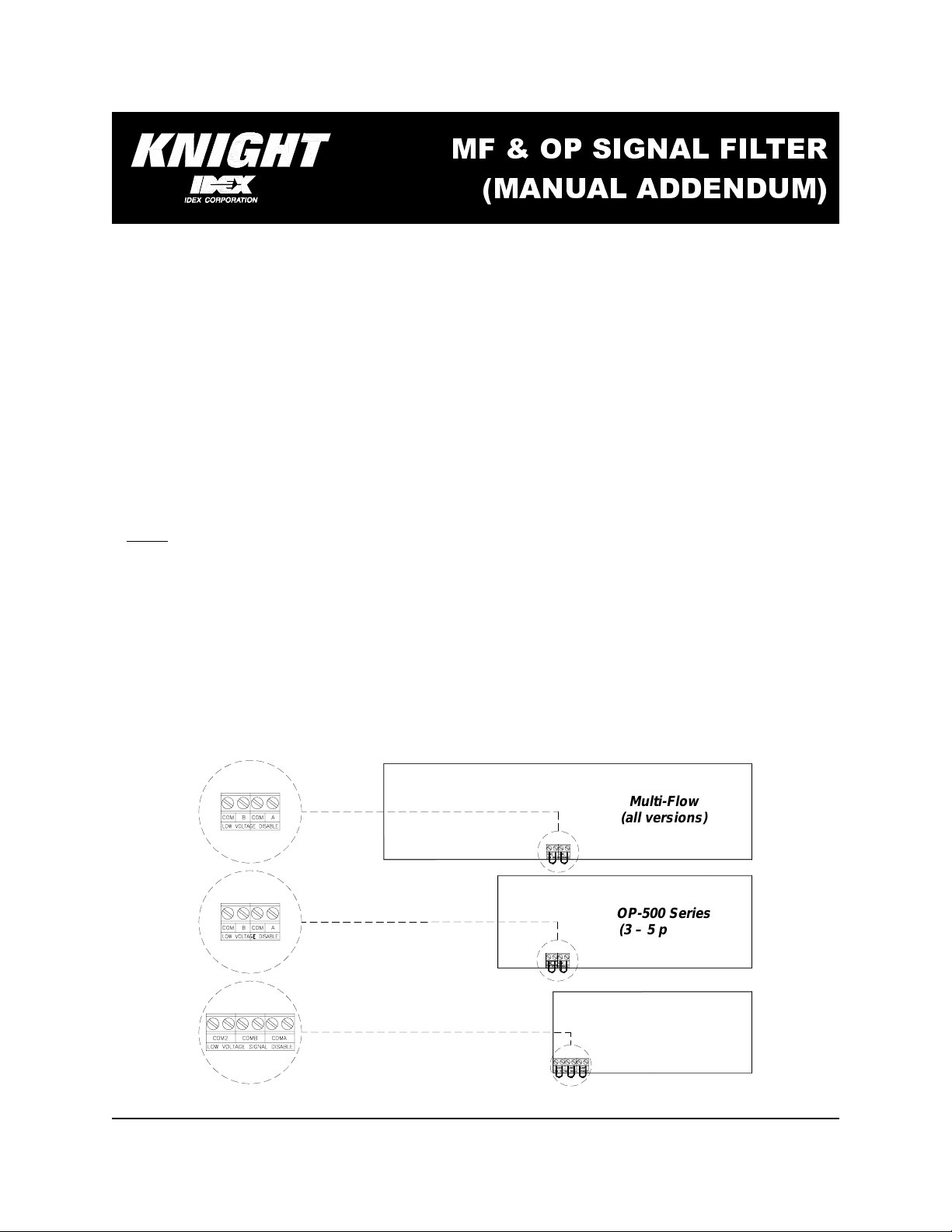
The following steps apply to both the Multi-Flow and On-Premise Series
(1) Locate the signal filtering jumper wires using the diagram below for reference.
(2) To filter signals that use common A, remove the jumper wire from the terminals marked “COM A LOW
VOLTAGE DISABLE“.
(3) To filter signals that use common B (if required), remove the jumper wire from the terminals marked “COM B
LOW VOLTAGE DISABLE“.
(4) For OP-502 custom applications only: To filter signals that use common 2 (if required), remove the jumper wire
from the terminals marked “COM 2 LOW VOLTAGE DISABLE“.
Multi-Flow
(all versions)
OP-500 Series
(3 – 5 pumps)
OP-500 Series
(2 pump only)
0900883 Rev: REL (02/03)

DISCLAIMER
Knight Inc. does not accept responsibility for the mishandling, misuse, or non-performance of the described items
when used for purposes other than those specified in the instructions. For hazardous materials information consult
label, MSDS, or Knight Inc. Knight products are not for use in potentially explosive environments. Any use of our
equipment in such an environment is at the risk of the user, Knight does not accept any liability in such
circumstances.
WARRANTY
All Knight controls and pump systems are warranted against defects in material and workmanship for a period of
ONE year. All electronic control boards have a TWO year warranty. Warranty applies only to the replacement or
repair of such parts when returned to factory with a Knight Return Authorization (KRA) number, freight prepaid, and
found to be defective upon factory authorized inspection. Bearings and pump s eals or rubber and synthetic rubber
parts such as “O” rings, diaphragms, squeeze tubing, and gaskets are considered expendable and are not covered
under warranty. Warranty does not cover liability resulting from performance of this equipment nor the labor to
replace this equipment. Product abuse or misuse voids warranty.
KNIGHT INC.
World Headquarters: 20531 Crescent BayDrive, Lake Forest, CA 92630-8825 (USA) TEL: 949-595-4800, FAX:949-595-4801, www.knightequip.com
Atlanta Branch:
415 GeesMill Business
Court NE, Suite 200
Conyers, GA 30013 USA
TEL: 770-760-8777
FAX: 770-761-0199
Toronto Branch:
2880 Argentia Road, Unit 6
Mississauga, Ontario
L5N 7X8 Canada
TEL: 905-542-2333
FAX: 905-542-1536
London Branch:
#15 Brunel Centre
Newton Road, Crawley
West Sussex UK RH109TU
TEL: 44-1293-615570
FAX: 44-1293-615585
A Unit of IDEX Corporation
Sydney Branch:
Unit 28, 317-321
Woodpark Rd., Smithfield
NSW Australia 2164
TEL: 61-29-725-2588
FAX: 61-29-725-2025
AmsterdamBranch:
Marssteden 68
7547 TD Enschede
The Netherlands
TEL: 31-53-428-58-00
FAX: 31-53-428-58-09
0900883 Rev: REL (02/03)
Spain Branch:
Port Ginesta, Local 210
08860 Sitges
Barcelona Spain
TEL: 34-936-342-130
FAX: 34-936-643-477
 Loading...