

Knight Equipment On-Premise Pro Installation Manual
On-Premise Pro
Instruction Manual
0901133 Rev: A (11/13) Page 1 of 20

TABLE OF CONTENTS
Introduction ........................................................................................................... 4
Features ............................................................................................................... 4
Pre-installation ...................................................................................................... 5
Installation ............................................................................................................ 5
Operating Modes .................................................................................................. 6
Programming ........................................................................................................ 7
Load Counts ....................................................................................................... 10
Drain Mode ......................................................................................................... 11
Other Features ................................................................................................... 12
Troubleshooting .................................................................................................. 15
System Wiring Diagram ...................................................................................... 16
System Parts Diagram ........................................................................................ 17
Conformity Documentation ................................................................................. 19
Warranty Information .......................................................................................... 20
Knight Locations ................................................................................................. 20
Equipment Ratings
This includes equipment supply, description of I/O connections, duty cycle and operating environmental conditions.
1. Pollution degree 2;
2. Installation category 2;
3. Altitude 2000 m;
4. Humidity 50% to 80%
5. Power supply 100 - 240 VAC, 2.0 A, 50/60 Hz
6. Indoor use only;
7. Temperature 5°C to 40°C;
8. Mains supply voltage fluctuations are not to exceed 10 percent of the nominal supply voltage;
Electrical Ratings
Chemical dispensing pumps, Models OP-PRO, permanently connected, rated 100 - 240 VAC, 2.0 A, 50/60 Hz
Replacement on I/O Board: 2Amp, 250V, 6.3x32mm, Fast-Acting
Replacement on PCB inside SIB Module: 0.5Amp, 250V, 6.3x32mm, Fast-Acting
Approvals mark:
CAUTION: Wear protective clothing and eyewear when dispensing chemicals or
other materials. Observe safety handling instructions (MSDS) of chemical mfrs.
CAUTION: To avoid severe or fatal shock, always disconnect main power when
servicing the unit.
CAUTION: When installing any equipment, ensure that all national and local
safety, electrical, and plumbing codes are met.
Page 2 of 20 0901133 Rev: A (11/13)

8
1
3
5
QUICK-START PROGRAMMING
6
10
4
9 2 7
The steps below will give you just the basics to quickly setup a new system — more details and complete
programming information are included in the following pages of this manual.
(1) Press once (for default 000 access code).
(2) Press ENTER...―ACC‖ will flash briefly on the display. You now have access.
(3) Note that the pump time LED will be flashing.
(4) Press pump SELECT until desired pump number is displayed.
NOTE: If using a flush manifold, program pump ―F‖ on all formulas to set flush time.
(5) Press formula SELECT until desired formula number appears.
(6) Use / to input the pump time or flush time (or delay time) in seconds.
(7) Press ENTER…the display will flash indicating that your entry has been saved.
(8) To program a pump delay time, press MODE until delay time LED is flashing. Repeat steps 4 – 7.
(9) To set the load count pump, press ENTER twice (note that pump time & delay time LEDs turn off). Use pump
SELECT to choose the pump number that will be used to count loads for each formula. After a few seconds, the
pump time LED will return, indicating that your entry has been saved.
(10) Press RESET when finished programming and ready to run.
0901133 Rev: A (11/13) Page 3 of 20
INTRODUCTION
FEATURES
The On-Premise Pro was designed to meet today’s
laundry chemical injection needs with economy and
flexibility in mind. Advanced microprocessor technology
makes the OP-Pro one of Knight’s least expensive
laundry injectors, yet has all the features to meet every
type of on-premise laundry condition.
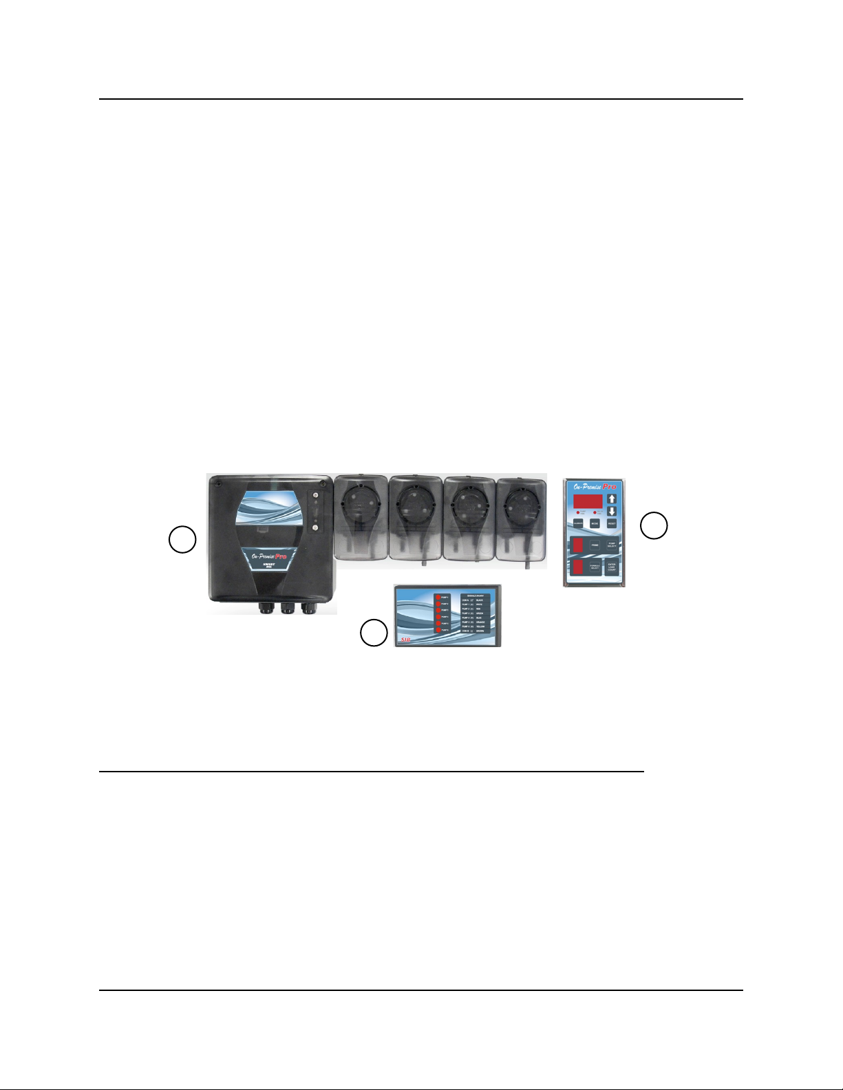
The On-Premise Pro is a three component system, with
each component performing a specific function. See
diagram below for illustration of the following:
(1) The Signal Interface Module (SIB) receives supply
signals from the washmachine.
(2) Signals are routed to the Remote Control which
controls all timing and programming functions.
Pump run times and delay times are activated for
the selected formula number.
(3) The output circuit board located inside the pump
cabinet then runs the pumps for the correct amount
of time.
3
8 formula capability for various soil conditions
Independent pump run times to provide specific
volume injections
Individual delay times for all wash formulas gives
greater flexibility with ―fixed‖ timer washwheels
Programmed data is stored in non-volatile memory
and not affected by voltage spikes or power outages
Optional Drain Mode and Relay Mode
Optional Auto Formula Select
Formula and level enable/disable capability
Flush mode can be used with all modes of operation
Optional flush manifold with solenoid provides single
line diluted chemical injection
LED display on the remote control lets the user know
which pump is running, and which formula is active
The signal input circuitry will accept and verify a
signal that is in the range of 24 to 240 volts
2
1
QUICK-REFERENCE
Listed below is a guide for quickly setting features that are explained in detail throughout this manual. As a reminder,
you must have access (enter access code) to change any of the settings.
Setting Formula # Pump # Range/Choice
Access code A 1 0 – 255
Signal lockout time A 2 0 – 75 minutes
Delay units A 3 1 = seconds 60 = minutes
Pump 7 & 8 enable A 4 0 = disabled 1 = enabled
Drain mode A 5 0 = disabled 1 = enabled
Invert drain signal A 6 0 = normal 1 = inverted
Levels disable A 7 0 = levels 1 = no levels
System reset timer A 8 0 – 75 minutes
Auto formula select time A A 0 = disabled 1 — 5 to select time
Auto formula select mode A F 0 = micro 1 = chart
* Formula disable Various F 0 = enable 1 = disable
NOTE: The pump time LED must be flashing when setting all features above, except formula disable.
* Delay time LED must be flashing when setting the formula disable feature (only).
Page 4 of 20 0901133 Rev: A (11/13)

PRE-INSTALLATION
Before the equipment is installed, you should survey the
installation site thoroughly. At the very least, your survey
should include the following:
Check to make sure that all functions of the
washmachine are operating properly. Including; card
reader or timer, water solenoids, flush down valves,
water level switch, machine motor, and drain valve.
Check the proposed location for a 100 to 240 VAC
power source.
Check voltage of all supply signals that will be used
from the washmachine. Measure voltage between
supply signal and signal common with a voltmeter.
DO NOT check signal voltage between supply signal
and case (earth) ground.
Measure the distance from chemical supply
containers to pump housing, and from pump housing
to injection point inside washmachine.
INSTALLATION
(1) Disconnect all power to washer.
(2) Mount pump cabinet in a convenient location no
higher than 8’ above, and within 10’ horizontally, of
supply containers. This is usually near the washer,
however dispenser can be mounted as a remote
pumping system.
(3) Using the provided mounting bracket, mount the
Remote Control to the front of the washer where
operators can easily access it. Secure the bracket
to washer using provided mounting screws or DualLock fastening strips (be sure to first clean the
mounting surface as the adhesive will not stick to a
dirty surface). Connect the low voltage cable from
the remote to the pump cabinet.
(4) Connect 100 to 240 VAC power source to main
power connection in pump cabinet. Use suitable
conduit for electrical wiring (per applicable wiring
codes). NOTE: Low voltage cables do not require
conduit.
(5) Install and wire the Signal Interface Module (SIB)
per notes to the right.
(6) For each pump, cut the suction tube to length and
insert one end into the appropriate supply container
using PVC pipe as a support. Insert other end of
suction tube into the left (input) side of the pump’s
squeeze tube.
(7) For each pump, cut the discharge tube to length
and insert one end into the right (output) side of the
pump’s squeeze tube. Form an anti-siphon loop
(pointing ―down―) with the other end of discharge
tube and insert into the supply pocket of the
machine.
(8) The system is now ready to be powered up and
programmed.
The Signal Interface Module (SIB):
The SIB receives supply signals from the washer, then
communicates with the dispenser to run the pumps. The
low voltage cable allows a quick, clean connection from
the module to the pump system without requiring
conduit.
(1) Mount the module using the provided Dual Lock
adhesive strip. The module can be mounted inside
the washer’s controls, along side the washer’s
controls, or to the bottom of the pump cabinet.
(2) Connect the low voltage cable from the module to
the OP-Pro pump system.
(3) Connect the supply signals to the SIB per wire
colors on the SIB label. If using Drain Mode, only
one signal is required (pump #1).
(4) If you have one signal common (typical) connect
the common to ―COM A‖ on the SIB. If you have
two signal commons, you will need to remove a
resistor inside the SIB before connecting the
common wires! See the following details.
Splitting signal commons:
(1) Remove the four screws from the bottom of the SIB
to open the module.
(2) Locate the three resistors marked R1, R2, and R4,
on the left side of the module (each resistor has a
single black band).
(3) Cut and remove the resistor that will ―split‖ the
commons between the desired pumps. Be sure to
remove only one resistor.
CUT RESISTOR
R2 1, 2 3, 4, 5, 6
R1 1, 2, 3 4, 5, 6
R4 1, 2, 3, 4, 5 6
TO USE COM A
FOR PUMPS
AND COM B
FOR PUMPS
(4) Close the module and replace the four screws
when finished.
0901133 Rev: A (11/13) Page 5 of 20

OPERATING MODES
Normal operation:
The system is capable of 8 user selectable formulas
with each formula having unique run times and delay
times for each pump. Signals from the washer trigger
the pumps, then the On-Premise Pro’s microprocessor
takes control to count down delay and/or run times.
Wash formulas can be selected by either of the two
following options:
The machine operator can select the formula using
the formula SELECT button to choose the appropriate
wash formula before the washcycle begins.
Auto formula select can be used to allow the washer
to control the formula choice with a signal.
The first time pumps 1 - 6 are signaled, they will run
―level‖ 1. The next time these pumps are signaled in the
same formula, they will run ―level‖ 2 providing that any
signal lockout time (if used) has expired. Pumps 1 - 6
will not run again until the Load Count Pump is signaled,
formula number changed, or the RESET button is
pressed.
No more than 3 pumps (if applicable) should be
programmed to run simultaneously.
Pumps 1 - 6 are the only pumps with ―two level‖
capability. Level 1 can be ―skipped over‖ if desired, by
not programming any pump run time for that level.
When the first signal is applied, no pump action will
occur — the second signal will then activate the
second level as usual.
Relay mode:
The intended use of relay mode is for machines that are
microprocessor controlled. The pumps run for as long
as their respective signals are present. The system ―bypasses‖ its run time and delay time capabilities during
relay mode operation.
Formula numbers are not selectable in relay mode (as
they are not needed) — an ―r‖ will be displayed in the
formula number window indicating the system is in relay
mode. Flush mode can be used in relay mode if
chemicals are to be flushed with water to the washer.
To set relay mode, enter the access code, then use
FORMULA SELECT to choose formula ―r―. Set the load
count pump as explained in the Load Count section.
(Note: There is a one second qualifying time in relay
mode. For the pump to run for 10 seconds the signal
must be set for 11 seconds.)
Drain mode:
Drain Mode maximizes the versatility of the OP-Pro by
providing a simple and reliable signal interface to
washers that do not have typical supply signal
connections, or where the washer’s supply signals are
not operating correctly.
Installation time is quicker, as there is only one signal
source required from the washer for Drain Mode to
operate. See page 11 for complete details.
Flush mode:
The Flush Pump turns on with any pump running, then
activates its own programmed run time when the pump
shuts off. The system ―looks‖ for contact at the flow
switch terminals (see wiring diagram) to verify proper
flush. If a flow switch is not used, jumper JP1 should be
in place. A ―flush error‖ happens when no contact is
detected (switch or jumper) at the FLUSH ERR
terminals while only the Flush Pump runs. Flush errors
are indicated by the Remote Control flashing and ―F‖ in
the pump window. Also, the buzzer (optional) will sound.
Programming pump ―F‖ is only required for systems that
will inject with a flush manifold.
Page 6 of 20 0901133 Rev: A (11/13)
 Loading...