

Knight Equipment EDP-0.4 Installation Manual
INSTRUCTION MANUAL
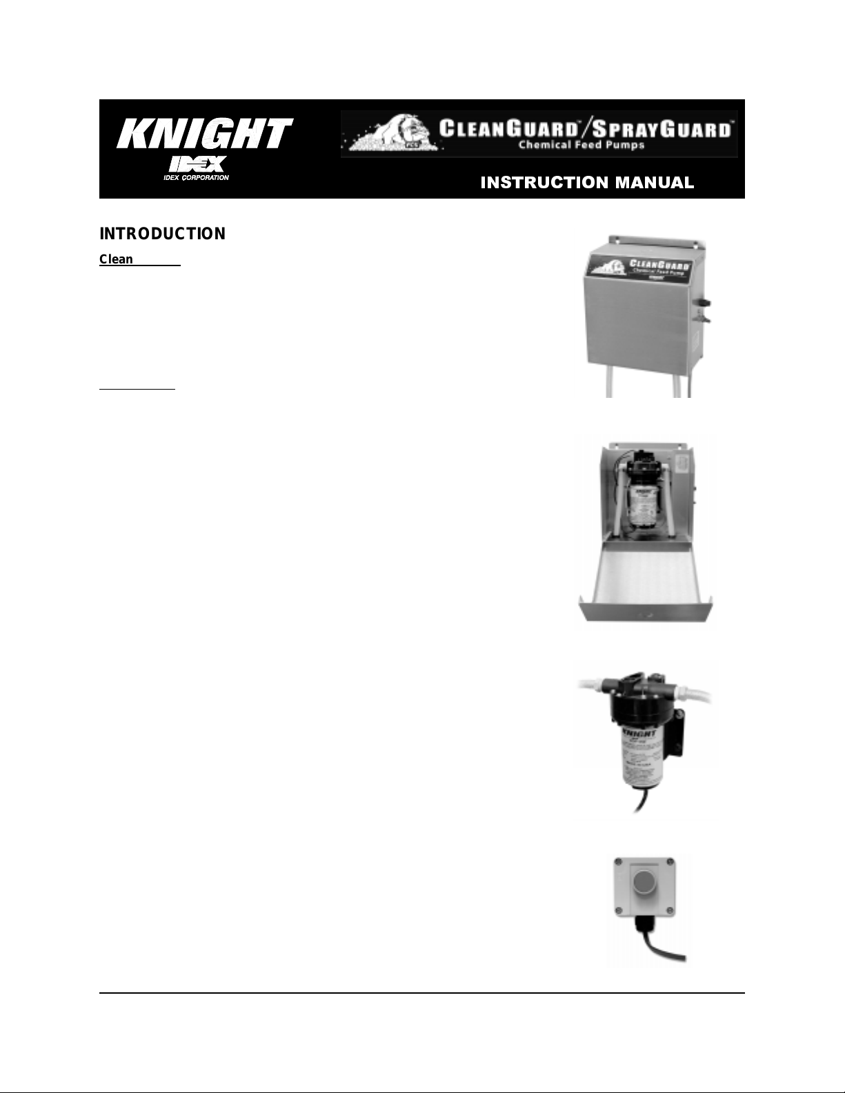
INTRODUCTION
Clean Guard is Knight’s newest pump designed to feed chemicals
formulated for the dairy farm, food and beverage, and commercial laundry
markets. Its quiet, smooth pumping operation is driven by a 115 or 230 VAC
rectified DC motor with long life brushes. This pump is designed for control
by Knight’s Control Guard Dairy Chemical Control, Control Guard
Conductivity Controller, Control Guard XL, and laundry chemical feed
controls. These pumps are capable of continuous duty operation and seldom
require service.
Spray Guard
based cow teat cleaning chemicals to drop points or misting type spray
wands. Up to six spray wands or delivery points can be supplied from one
Spray Guard pump.
utilizes the same robust pump/motor design to dispense iodine
HOW IT WORKS
A brush-type DC motor turns the output shaft that’s connected to a unique
“wobbler plate” which in turn attenuates three or five elastomer checkvalve
chambers that create a vacuum on the suction side and pressures up to 70
PSI on the outlet. Diaphragms and checkvalves are completely sealed from
the outside and have no penetrating fasteners to create leaks or lose prime.
Pumps include special liquid-end fittings that lock in place over proprietary
barb-type fittings.
All Clean Guard and Spray Guard pumps include a pump mounted pressure
switch to protect the pump from damage while in a “dead head” condition.
For “demand flow” applications, this feature is ideal.
KEY FEATURES / BENEFITS
• Auto-Start or Optional Manual Button Activation
• Secure Moisture-Resistant Enclosure
• Long-Life Wobbler Plate Pump Design
• Long Lasting Diaphragm and Seals
• Fixed or Variable Pump Configurations
• 1.5 / 3.2 GPM Flow Rates—Clean Guard
• 0.4 GPM Flow Rate—Spray Guard
• Pump Protection Circuit w/Fuse
• Pumps Up to 70 PSI
• Self Priming, Easy to Service
Outside View
Inside View
Electric Diaphragm Pump
Remote Activator
0901162 Rev: A (12/06) Page 1 of 8
SPECIFICATIONS
• Pump Control Board: With proprietary signal, 24 VAC output (Spray Guard only)
• Pressure Switch: 70 PSI, N/C contacts
• Enclosure: Stainless steel #304
• Power Supply: 115VAC/50, 60HZ, 230VAC/50, 60HZ, 24 VAC/50, 60HZ
• Dimensions: Unit — 9 1/2”W x 11 1/2”H x 5 1/2”D (24cm x 29cm x 14cm)
• Max lift (suction): 10 feet
• Max head pressure: 70 PSI
• Max run time: Continuous duty (see note below)
NOTE: EDP series pumps are designed for intermittent duty, but may run continuously if the motor temperature does
not exceed the recommended limit.
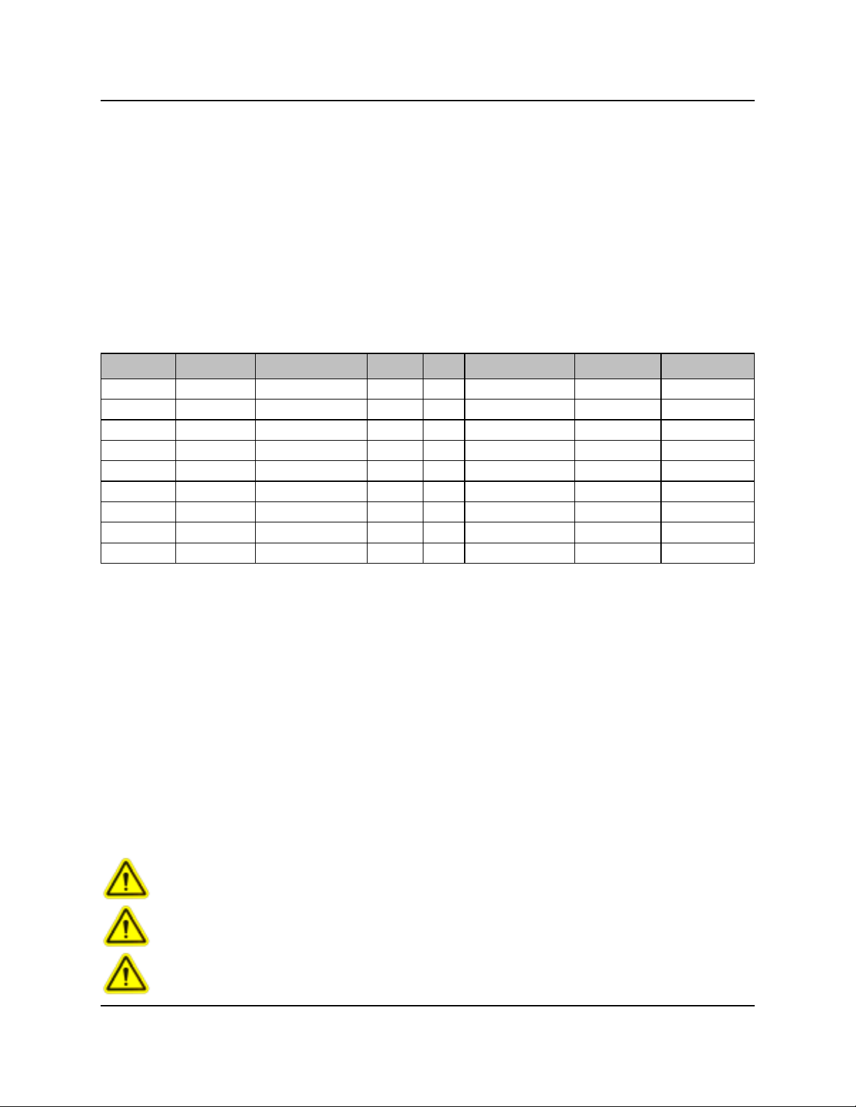
PART NO. MODEL NO. FLOW RATE VOLTS AMPS WET MATERIALS PRESSURE TUBE SIZE
7640620-04 EDP-0.4 0.4 GPM 24 VAC 0.7 VITON 70 PSI 3/8"
7640621-01 EDP-1.5 1.5 GPM 115VAC 0.8 EPDM 70 PSI 3/8"
7640622-01 EDP-1.5 1.5 GPM 115VAC 0.8 VITON 70 PSI 3/8"
7640623-01 EDP-3.2 3.2 GPM 115VAC 0.8 EPDM 70 PSI 3/8"
7640624-01 EDP-3.2 3.2 GPM 115VAC 0.8 VITON 70 PSI 3/8"
7640621-02 EDP-1.5 1.5 GPM 230VAC 0.4 EPDM 70 PSI 3/8"
7640622-02 EDP-1.5 1.5 GPM 230VAC 0.4 VITON 70 PSI 3/8"
7640623-02 EDP-3.2 3.2 GPM 230VAC 0.4 EPDM 70 PSI 3/8"
7640624-02 EDP-3.2 3.2 GPM 230VAC 0.4 VITON 70 PSI 3/8"
CAUTION: Wear protective clothing and eyewear when dispensing chemicals or
other materials. Observe safety handling instructions (MSDS) of chemical mfrs.
CAUTION: To avoid severe or fatal shock, always disconnect main power when
servicing the unit.
CAUTION: When installing any equipment, ensure that all national and local
safety, electrical, and plumbing codes are met.
Page 2 of 8 0901162 Rev: A (12/06)

IMPORTANT NOTES
• Maximum suction lift is 10 feet. That means suction hose length can be up to 10 feet, no longer.
• Recommended tubing is nylon braided hose with 3/8” inside diameter.
• No flow path restrictions, such as footvalves, checkvalves, or filters should be placed in the suction line.
• Do not operate the pump above the pressure limitations specified on the data label.
• Never operate the pump in a harsh environment or hazardous atmosphere, since motor brush and switch may
cause electrical arcing.
• As long as there is inlet liquid pressure, the pump will not stop the forward flow of liquid even if the motor is turned
off. Be sure the system has a positive means of shutting off liquid supply.
• Do not subject the pump to extreme high or low (freezing) temperatures while in operation. Ambient temperature
range for operation is 32° F to 115° F.
• Knight recommends the use of flexible tubing with proper pressure rating.
INSTALLATION
NOTE: See example installation diagram on page 5 for more information.
(1) Check voltage of installation with a voltmeter and compare with voltage inputs of pump unit before mounting.
Application of incorrect voltage will permanently damage unit and is not covered under warranty.
(2) Mount unit on wall or shelf in a convenient location near both injection point and chemical supply. Do not mount
unit in direct path of steam. This can short circuit and permanently damage your system.
(3) Install power leads. Most systems include a power cord for easy connection. Spray Guard systems have an
external transformer which steps down the incoming voltage. Rigid or flexible conduit should be used for all 115
and 230 VAC installations to ensure safety and continued operation without shorts. The green ground wire must
be applied to ground. Failure to do so will void warranty.
(4) Install vinyl hose between the discharge (right) tube side of the pump and the injection point. Use hose clamps to
secure tubing to fittings. For all hose routing, avoid any sharp bends which may crimp tubing and restrict flow. As
an alternative, use 90 elbow fittings, but only if absolutely necessary.
(5) Install vinyl hose between the suction (left) tube side and the PVC product pickup tube provided.
PRIMING
(1) See dispenser controller manual for specific priming rout ine s.
(2) Initial prime should be performed using water as your media. Once the pump is primed with water the valves/
diaphragm are ready for chemical.
(3) Pump will prime only if all pressure is relieved from outlet port.
NOTE: If the pump fails to prime, pour a small amount of water into the suction port while the pump is running, then
re-connect the suction hose.
0901162 Rev: A (12/06) Page 3 of 8
 Loading...