

Knight Equipment Dial-A-Chem Installation Manual
INSTRUCTION MANUAL
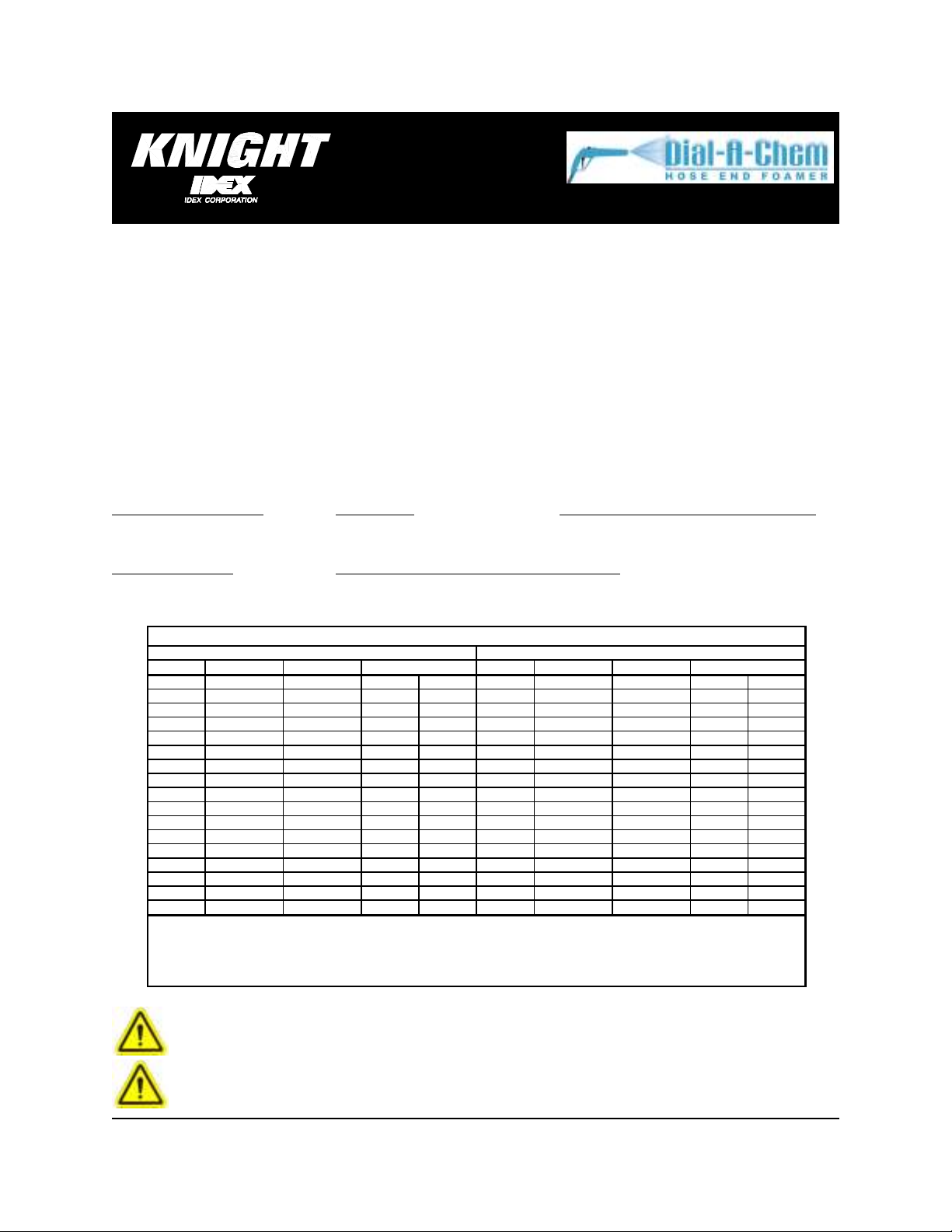
Flowrate
1 gallon
9 liter
Flowrate
1 gallon
9 liter
Color
oz/gal
ml./lit.
ratio%Color
oz/gal
ml./lit.
ratio
None
None
White
White
Yellow
Yellow
Pink
Pink
Dk Green
Dk Green
Black
Black
Brown
Brown
Gray
Gray
Blue
Blue
Red
Red
Peach
Peach
Lt Blue
Lt Blue
Purple
Purple
Lt Green
Lt Green
Orange
Orange
Lt Brown
Lt Brown
INTRODUCTION
The Dial-A-Chem combines the best of both worlds by creating the first all-in-one portable, self-contained foam
cleaning and sanitizing system that delivers rich and consistent foam to any hard surface. The revolutionary new
product allows for switching between foam, sanitizer, or rinse with a simple turn of the dial, while the chemical is left
behind allowing for unlimited chemical supply and easy portability.
IMPORTANT NOTES
•
Unit supplied without a backflow prevention device. To prevent possible chemical backup into the water supply,
comply with all local plumbing codes and install an appropriate backflow prevention device.
•
Do not leave unit unattended with trigger handle in locked position.
SPECIFICATIONS
Max Water Temperature Foam Throw Rinse & Sani Flow rates (GPM) (Lit./Min.)
Min 25°F (N/A) 30 PSI 8-10ft (2,4-3 m.) 30 PSI (2 Bar) Refer to Metering Tip Chart
Max 150°F (65 °C) 60 PSI 8-10ft (2,4-3 m.) 60 PSI (4 Bar) Refer to Metering Tip Chart
Operating Pressure
Flashpoint of Blue PVC outside hose covering
Min 30 PSI (2 Bar) 150°F (65 °C)
Max 80 PSI (5,5 Bar)
Metering Tip Chart
Foam Acid
20.9 163 6.1:1 16.3
19.6 153 6.5:1 15.3
18.6 145 6.9:1 14.5
15.6 121 8.2:1 12.1
12.2 95 10.5:1 9.5
9.5 74 13.5:1 7.4
7.4 57 17.3:1 5.7
5.1 39 25:1 3.9
4.1 32 32:1 3.2
3.4 26 38:1 2.6
2.7 21 48:1 2.1
2 15 64:1 1.5
1.7 13 76:1 1.3
1.4 10 92:1 1
0.3 2 430:1 0.2
0.2 1 640:1 0.1
NOTE: The above chart is based upon the chemical viscosity of water (CPS = 1.0) and should only be used as a guide - the
values were derived using water as the working fluid and 40 PSI (2,75 Bar) dynamic input pressure through a 50 ft (16 meter)
hose. Actual ratios and flow rates may vary due to product viscosity, flow, pressure and tubing.
18.9 147 6.8:1 14.7
%
17.6 137 7.3:1 13.7
16.9 132 7.6:1 13.2
15.6 121 8.2:1 12.1
12.2 95 10.5:1 9.5
9.5 74 13.5:1 7.4
7.4 57 17.3:1 5.7
5.1 39 25:1 3.9
4.1 32 32:1 3.2
3.4 26 38:1 2.6
2.7 21 48:1 2.1
2 15 64:1 1.5
1.7 13 76:1 1.3
1.4 10 92:1 1
0.3 2 430:1 0.2
0.2 1 640:1 0.1
CAUTION: Wear protective clothing and eyewear when dispensing chemicals or
other materials. Observe safety handling instructions (MSDS) of chemical mfrs.
CAUTION: When installing any equipment, ensure that all national and local
safety, electrical, and plumbing codes are met.
0900425 Rev: REL (05/08) Page 1 of 4

INSTALLATION
(1) Mount the hose bracket to the wall using the screws and anchors provided.
(2) Trim back the protective cover to expose the hoses inside. Be careful to not cut or nick the hoses and ensure
that the cover is stripped back far enough so that the large (water) hose can run from the bracket to the water
source. If necessary, the smaller (chemical) hoses can be trimmed to a shorter length.
(3) Route the large (water) hose and the two smaller (chemical) hoses downward through the large hole at the
bottom of the bracket.
(4) Connect the large water hose to water supply and secure with a hose clamp. Use the 1/2” barb fitting in the
accessory kit to adapt the hose to the water supply. Be sure to comply with all local codes pertaining to backflow
prevention. Contact Knight for information regarding approved backflow prevention devices for your area. Water
pressure should be 30—80 PSI (2—5.5 BAR). Water temperature should not exceed 150°F (65°C).
(5) Locate the chemical containers below the hose bracket. If the chemical containers will be housed in an enclosure
or rack, be sure to allow enough room to coil the hose on the hose bracket.
(6) If you wish to use a cap on top of your chemical containers, drill a hole in the top of each cap large enough to
pass the chemical line through.
(7) Select the appropriate metering tip (see metering tip chart) and screw into the small end of the footvalve.
(8) Route the end of the chemical line through the hole in the cap (if applicable) then slide the ceramic weight over
the end of the chemical line.
(9) Insert the footvalve into the end of the chemical line and drop the footvalve into the appropriate chemical
container. If a cap is used, tighten the cap down on top of the container. Feed enough slack into the container so
that the footvalve sinks to the bottom.
NOTE: The way that you can tell the chemical lines apart is to look at the open end of the hose with the larger
hose on top and the smaller hoses on the bottom. The left smaller hose is for sanitizer and the right smaller hose
is for detergent.
(10) Repeat for other chemical container.
OPERATION
(1) Turn on the water supply.
(2) Prime the chemical lines by using the selector knob to choose the chemical, then squeeze the handle to activate
the water flow.
(3) Check the sanitizer level by choosing the sanitizer with the selector knob, then activate the handle and spray a
small amount into a bucket or catch pan. Use test strips on the sample to determine the sanitizer level.
(4) To dispense foam, use the selector knob to choose foam, then squeeze the handle. Point the discharge end
toward the surface to be cleaned and move the end back and forth to cover the area.
(5) To rinse, rotate the selector knob to the rinse position and squeeze the handle. The rinse water will spray out in a
wide fanned out pattern. Move the end back and forth to rinse down the cleaning surface. No chemical will be
dispensed when using the rinse feature.
(6) To sanitize, rotate the selector knob to the sanitizer position and squeeze the handle. The sanitized water will
spray out in a wide fanned out pattern. Move the end back and forth to sanitize the cleaning surface.
NOTES:
•
The trigger handle can be locked into the “ON” position with the small metal loop just below the bottom of the
handle.
•
Turn off the water supply and coil the hose on the bracket when not in use.
Page 2 of 4 0900425 Rev: REL (05/08)
 Loading...