

Knight Equipment DDS-1000TB Installation Manual

DDS-1000TB
INSTRUCTION MANUAL
THEORY OF OPERATION
The DDS-1000TB Dry Dispensing System is designed to dispense one solid product and liquid bleach into a washer.
Each dispenser includes a 24 volt water solenoid, Power Bowl Ultra dry detergent feeder (with vacuum breaker),
peristaltic pump, step-down transformer, limit-timer control boards, fully assembled and ready to install.
The DDS-1000TB is designed as a “stand alone” two product dispenser for automatic injection of chemical for onpremise laundry machines. It can be manually activated by the operator using the external dispense switches, or
connected to washer supply signals for automatic operation.
The dispenser features two KTM-500 timing modules that include a unique button programmable feed timer and a
“Lock-Out” feature that is designed to prevent consecutive dispensing where cost containment and control is
required. The KTM-500 also features a delay time function, and a “Relay Mode” which allows for a timed signal from
a microprocessor laundry machine to control the feed time.
The DDS-1000TB will start a feed cycle when the Start button is pressed or when the signal input terminals receive
an external 14-240 VAC trigger signal.
GETTING STARTED
Be sure to inspect the installation site prior to beginning your installation. It’s important that you locate the source for
dispenser power and signals as well as hot water. To complete the installation, you may need the following parts:
• Hose “Y” with 3/4" female garden hose thread
• High pressure hose, 3/4" MGHT x 3/4" FGHT
• #10 x 1" sheet-metal screws and wall anchors
• Optional top-mount bracket kit #7600668 is av ailable for top mounting the dispenser on the laundry machine
INSTALLATION
(1) Mount the DDS-1000TB on the wall in a convenient location for operators to load and unload product containers.
The dispenser should be installed above the vertical height of the injection point on the washer.
(2) To connect the solid detergent feed line, connect the 5/8" ID vinyl injection tubing supplied with the unit to the
outlet fitting on the bottom of unit. Cut the discharge tubing to desired length and secure to washer supply inlet
point. A 70° elbow barb fitting is supplied for connection to washer.
(3) If an injection point is not available or desired, the injection tube can be manually placed in the machine each
load.
(4) To connect the bleach pump, insert one end of the 1/4" suction tube into the left side of the squeeze tube in the
peristaltic pump. Cut the suction tube to length and insert the other end into the supply container using PVC pipe
as a support.
(5) Insert one end of the discharge tubing into the right side of the squeeze tube in the peristaltic pump. Form an
anti-siphon loop (with the loop pointing “down“) with the other end of the discharge tubing and insert the end into
the supply pocket of the machine.
(6) Locate the chemical supply outputs on the washer for each product you wish to dispense. These outputs are
used to start the time feed sequence controlled by the internal KTM-500 control boards.
(7) The dispenser must have constant power in order to feed when the washer signals for chemical. Locate a
constant source of power (115/208/230 VAC) and connect to the power input terminals on the primary side of the
transformer (see wiring diagram on page 4). Use only approved electrical conduit and connect at bottom of
0900912 Rev: C (05/07) Page 1 of 8

dispenser using conduit fittings. Always use a voltmeter to check power, and turn power off during installation.
(8) Connect the water source to the dispenser using a 3/4" male garden hose fitting, or 1/2" FNPT x 1/2" barb brass
fitting to nylobraid tubing, or to hard-plumb use 1/2" FNPT x 1/2" sweat (copper) fitting. A 3/4" hose “Y” can be
used to plumb the dispenser between the water source and the washer (see diagram on page 5).
Important:
with chemical manufacturer for recommended water temperature and optimum pressure.
(9) To maintain consistent injections, water pressure should be regulated at 25-50 PSI. Water temperature and
pressure will determine required dispenser run time.
(10) Connect the vacuum breaker to the unit using the supplied copper tubes. Tighten compression fittings on the
inlet and outlet fittings and check for leaks.
Check all local plumbing codes for backflow prevention and water line connection standards. Check
CONNECTING WASHER SUPPLY SIGNAL FOR AUTOMATIC DISPENSING
Locate the chemical supply signals in the washer. Connect the chemical signal common and hot leads to the
terminals on the KTM-500 circuit board marked “SIG IN“. The KTM-500 circuit board will accept supply signal
voltages from 14 to 240 VAC. The supply signal must be a minimum 5 seconds to activate chemical injection.
PROGRAMMING
Run Time:
(1) Locate the dip-switch pack on the circuit board — set switch #6 to SIGNAL, set switch #7 to RUN TIME and set
(2) Using a measuring cup or flask, press Start switch and release when feed starts. Let the unit feed until desired
(3) Set mode switch #8 to RUN MODE.
Delay Time:
(1) Locate the dip-switch pack on the circuit board — set switch #6 to SIGNAL, set switch #7 to DELAY TIME and
(2) Press Start switch and release when the LED begins flashing. When the desired delay time has passed, press
(3) Set mode switch #8 to RUN MODE.
Lock-Out Time:
This feature defeats consecutive dispensing of product for a pre-determined interval. Select a combination of
switches 1 – 5 to program total lock-out time.
Example: For 10 minute lock-out, set switches #2 and #4 to ON with all other switches OFF.
For maximum lock-out (31 min) set all switches ON.
For no lock-out, set all switches OFF.
NOTE: If both KTM-500 circuit boards are connected to each other via the “lockout signal wiring” (L/O SIG terminals)
then both boards will be locked out from operation when either one has a lockout time active.
(max run time is 12 minutes and 42 seconds)
switch #8 to PROGRAM MODE.
amount of chemical is dispensed then press Start switch again to stop. The run time is now programmed. Repeat
step if new volume is required.
(max delay time is 12 minutes and 42 seconds)
set switch #8 to PROGRAM MODE.
the Start switch again. The delay time is now programmed. Repeat step if new delay time is required.
(max lock-out time is 31 minutes)
OPERATION
Manual activation:
will begin counting down the delay time (if used) and will then dispense for the amount of time programmed. Once the
lock-out time expires the unit will be ready to restart.
Signal activation:
seconds, the delay time (if used) will begin counting down. Then unit will dispense for the amount of time
programmed. Once the lock-out time expires the unit will be ready to restart.
Relay Mode:
Page 2 of 8 0900912 Rev: C (05/07)
Press the Start button on the cover or on the remote switch box for 1 full second. The KTM-500
When the signal input on the circuit board receives a 14-240 VAC trigger signal for at least 5 full
Set switch #6 to RELAY. The feed will activate for as long as an external trigger signal is present, or for
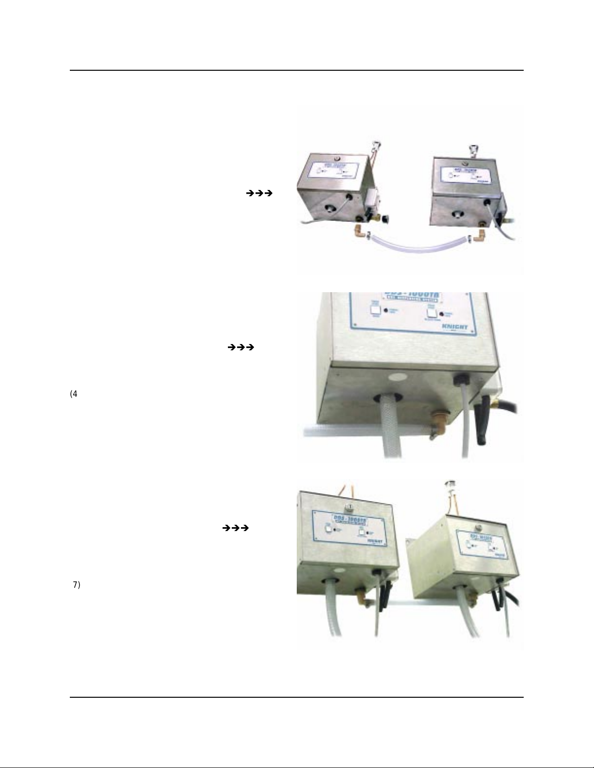
MULTIPLE UNIT CONNECTION
Connecting multiple DDS-1000 dispensers is quick
and easy with the DDS-1000 Connector Kit (Part
Number 7600672).
(1) Align units on the mounting surface side by side
and as close together as possible. Kit includes a
15 inch length of ½” ID Nylobraid tubing.
(2) Remove ½” plastic plug from brass “T” on bottom
of unit.
(3) Replace plug with ½” NPT x ½” Barb Elbow
fitting. Be sure to use plumbing tape or pipe
sealing compound to prevent leaks.
(4) Repeat above procedure for each unit connected.
(5) Insert plastic plug into ¾” hose adapter on each
unit except the unit closest to the water source.
(6) Connect ½” Nylobraid tubing to Barb Fittings
using stainless steel hose clamps.
(7) Connect “Source” water supply hose to unit
closest to water supply.
(8) Turn on water supply, press detergent / bleach /
softener start buttons and check for leaks.
0900912 Rev: C (05/07) Page 3 of 8
 Loading...