

Page 1

DDS-1000
INSTRUCTION MANUAL
THEORY OF OPERATION
The DDS-1000 Dry Dispensing System is designed to dispense solid, or “screen-feed” chemicals into a washer. Each
dispenser includes a 24 volt water solenoid, Power Bowl Ultra dry detergent feeder (with vacuum breaker), step-down
transformer, fully assembled and ready to install.
The DDS-1000 is designed as a “stand alone” dispenser that can be used on any top-load or front-load laundry
machine. The DDS-1000 feed time is controlled by the laundry machine programmer.
GETTING STARTED
Be sure to inspect the installation site prior to beginning your installation. It’s important that you locate the source for
dispenser power (signal) as well as hot water. To complete the installation, you may need the following parts:
• Hose “Y” with 3/4" female garden hose thread
• High pressure hose, 3/4" MGHT x 3/4" FGHT
• #10 x 1" sheet-metal screws and wall anchors
• Optional top-mount bracket kit #7600668 is av ailable for top mounting the dispenser on the laundry machi ne
INSTALLATION
(1) Mount the DDS-1000 on the wall in a convenient location for operators to load and unload product containers.
The dispenser should be installed above the vertical height of the injection point on the washer.
(2) Connect the 5/8" ID vinyl injection tubing supplied with the unit to the outlet fitting on the bottom of unit. Cut the
discharge tubing to desired length and secure to washer supply inlet point. A 70° elbow barb fitting is supplied for
connection to washer.
(3) If an injection point is not available or desired, the injection tube can be manually placed in the machine each
load.
(4) Locate the chemical supply signal outputs on the washer for each dispenser you wish to signal. The signal must
be maintained for the duration of dispensing time.
(5) Route the supply signal wiring (usually 115/208/230 VAC) from the washer to the dispenser power input barrier
located on the vertical stainless steel panel. A 24 VAC signal can also be wired directly to the solenoid coil (see
wiring diagram on page 4).
(6) Connect common leg to the terminal marked “common” and the hot leg to the terminal marked with the same
voltage as that coming from the washer. Use approved electrical conduit to route signals to dispenser.
NOTE: Disconnect power before wiring to the dispenser. Always check power with a voltmeter prior to
connecting to dispenser.
0900969 Rev: C (05/07) Page 1 of 8
Page 2

(7) Connect the water source to the dispenser using a 3/4" male garden hose fitting, or 1/2" FNPT x 1/2" barb brass
fitting to nylobraid tubing, or to hard-plumb use 1/2" FNPT x 1/2" sweat (copper) fitting. A 3/4" hose “Y” can be
used to plumb the dispenser between the water source and the washer (see diagram on page 5).
Important:
with chemical manufacturer for recommended water temperature and optimum pressure.
(8) To maintain consistent injections, water pressure should be regulated at 25-50 PSI. Water temperature and
pressure will determine required dispenser run time.
(9) Connect the vacuum breaker to the unit using the supplied copper tubes. Tighten compression fittings on the
inlet and outlet fittings and check for leaks.
(10) See page 3 for connecting multiple units.
Check all local plumbing codes for backflow prevention and water line connection standards. Check
CONTROLLING FEED TIME
The chemical dosage, or feed time, of the DDS-1000 is controlled directly by the washer’s supply signal. Supply
signals should be programmed (at the washer) for the length of time required to dispense the required amount of
chemical for each operation. Consult the washer manual for programming of the washer’s supply signal outputs.
Page 2 of 8 0900969 Rev: C (05/07)
Page 3
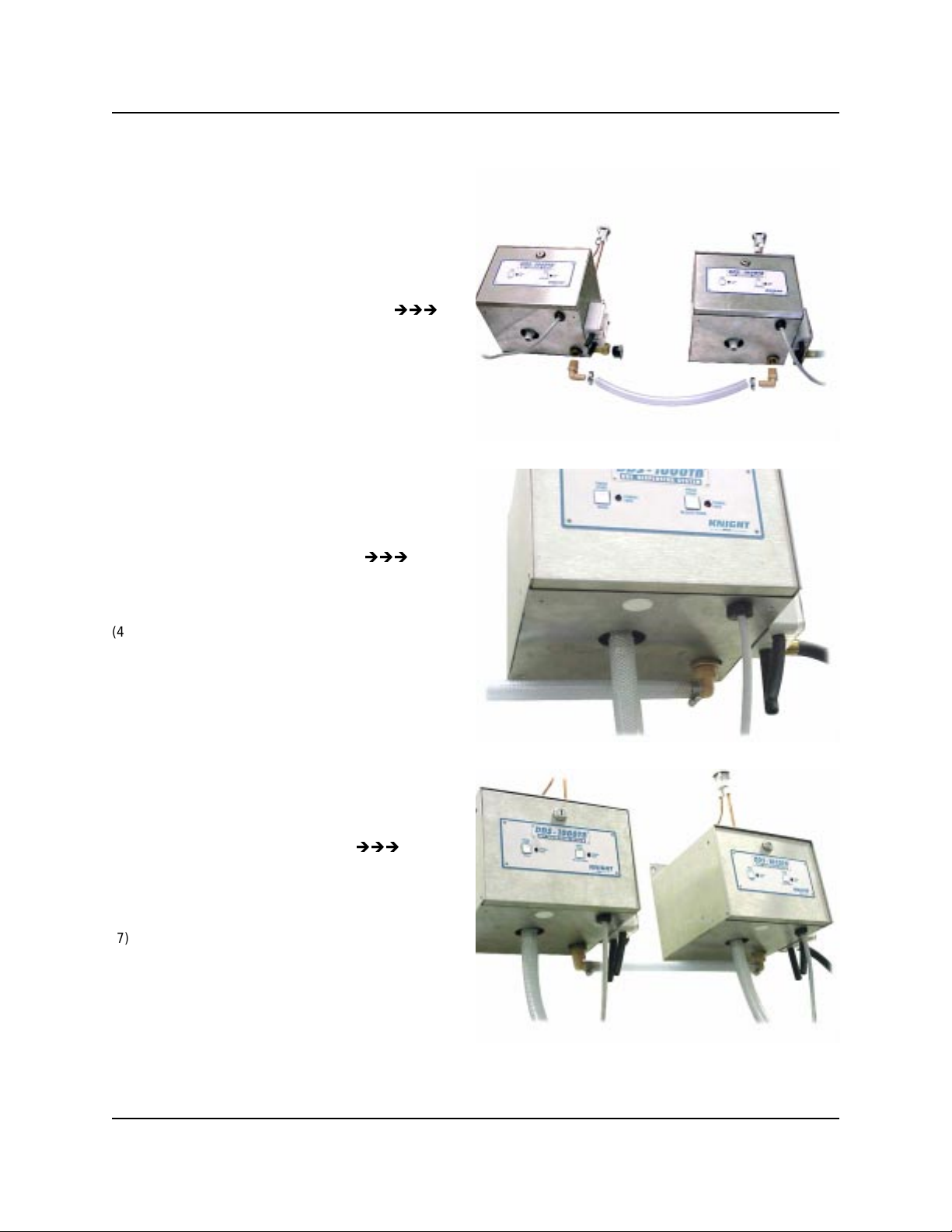
MULTIPLE UNIT CONNECTION
Connecting multiple DDS-1000 dispensers is quick
and easy with the DDS-1000 Connector Kit (Part
Number 7600672).
(1) Align units on the mounting surface side by side
and as close together as possible. Kit includes a
15 inch length of ½” ID Nylobraid tubing.
(2) Remove ½” plastic plug from brass “T” on bottom
of unit.
(3) Replace plug with ½” NPT x ½” Barb Elbow
fitting. Be sure to use plumbing tape or pipe
sealing compound to prevent leaks.
(4) Repeat above procedure for each unit connected.
(5) Insert plastic plug into ¾” hose adapter on each
unit except the unit closest to the water source.
(6) Connect ½” Nylobraid tubing to Barb Fittings
using stainless steel hose clamps.
(7) Connect “Source” water supply hose to unit
closest to water supply.
(8) Turn on water supply, press detergent / bleach /
softener start buttons and check for leaks.
0900969 Rev: C (05/07) Page 3 of 8
Page 4

DDS-1000 WIRING DIAGRAM
Page 4 of 8 0900969 Rev: C (05/07)
Page 5

DDS-1000 ASSEMBLY DIAGRAM
0900969 Rev: C (05/07) Page 5 of 8
Page 6

OPTIONAL WATER TEMPERING VALVE AND PRESSURE REGULATOR
We recommend the use of a water tempering valve and pressure regulator for optimal dry-feed performance.
Connect the tempering valve and pressure regulator before the water inlet of the DDS-1000 (see illustration below).
The tempering valve will allow the water temperature to be increased or decreased by turning the adjustment dial.
The adjustment range is 120° to 160° F. The pressure regulator will regulate the water pressure from 0 to 60 PSI.
Most manufacturers recommend pressure of 18-25 PSI (1.2 – 1.7 BAR) at a temperature of 120º-135° F (48°-57° C).
Connect to DDS-1000
Water Inlet
Cold Water
Pressure gauge assembly can be purchased at your local hardware store (see parts list below)
1 - 1/2” MNPT x 1/4” Brass Reducer
1 - 1/4” Pressure Gauge
2 - 1/4” Brass Close Nipple
7407118 Pressure
Regulator
Hot Water
7407119 Water Tempering
Valve
1 - 1/4” MNPT x 3/8” Barb
1 - 1/4” FPT Brass Tee
OPERATION
Insert a chemical capsule into the bowl of the DDS-1000. Run a few test cycles and inspect the operation of both the
washer and DDS-1000 to ensure proper chemical feed is achieved. Check all plumbing for leaks.
CALIBRATION OF SOLID DETERGENTS
As general rule of thumb program 10 seconds of run time for one ounce (28.3 grams) of detergent. For 2 ounces
(56.7 grams) set the run time for 20 seconds. First weigh the capsule (electronic scale may be needed) then start or
signal the dispenser. Weigh the capsule again after the run time is completed to calculate amount dispensed. Run the
capsule 2 or 3 times to see if the amount is consistent.
Page 6 of 8 0900969 Rev: C (05/07)
Page 7

TROUBLESHOOTING
Water leaking from inlet fittings
• Check for proper connection at fittings.
• Check for holes or splits on plumbing lines.
Chemical is not feeding
• Check washer signal for proper operation.
• Check to see if solenoid is opening properly.
• Check to see if water supply is on.
• Check inside of vacuum breaker for any debris or blockage.
• Check for proper water pressure.
• Check operation of Power Bowl Ultra water valve.
• Check operation of Power Bowl Ultra spray-jet.
Concentration too high or too low
• Check water temperature. Consult with solid chemical manufacturer for recommended temperature.
• Check water supply for fluctuations in pressure.
• Check feed time of control and adjust as needed.
Power Bowl Ultra is over-flowing
• Output hose is blocked, or plugged up.
• The end of the output hose is above the mounting height of the DDS-1000.
0900969 Rev: C (05/07) Page 7 of 8
Page 8

DISCLAIMER
Knight LLC does not accept responsibility for the mishandling, misuse, or non-performance of the described items
when used for purposes other than those specified in the instructions. For hazardous materials information consult
label, MSDS, or Knight LLC. Knight products are not for use in potentially explosive environments. Any use of our
equipment in such an environment is at the risk of the user, Knight does not accept any liability in such
circumstances.
WARRANTY
All Knight controls and pump systems are warranted against defects in material and workmanship for a period of
ONE year. All electronic control boards have a TWO year warranty. Warranty applies only to the replacement or
repair of such parts when returned to factory with a Knight Return Authorization (KRA) number, freight prepaid, and
found to be defective upon factory authorized inspection. Bearings and pump seals or rubber and synthetic rubber
parts such as “O” rings, diaphragms, squeeze tubing, and gaskets are considered expendable and are not covered
under warranty. Warranty does not cover liability resulting from performance of this equipment nor the labor to
replace this equipment. Product abuse or misuse voids warranty.
FOOTNOTE
The information and specifications included in this publication were in effect at the time of approval for printing.
Knight, LLC reserves the right, however, to discontinue or change specifications or design at any time without notice
and without incurring any obligation whatsoever.
Knight Headquarters
Tel: 949.595.4800
Fax: 949.595.4801
USA Toll Free
Tel: 800.854.3764
Fax: 800.752.9518
KNIGHT LLC,
Tel: 905.542.2333
Fax: 905.542.1536
A Unit of IDEX Corporation (www.knightequip.com)
Knight Canada
Knight Europe
Tel: 44.1293.615.570
Fax: 44.1293.615.585
Knight Australia
Tel: 61.2.9725.2588
Fax: 61.2.9725.2025
Knight N. Asia
Tel: 82.2.3481.6683
Fax: 82.2.3482.5742
Knight S. Asia
Tel: 65.6763.6633
Fax: 65.6764.4020
Page 8 of 8 0900969 Rev: C (05/07)
 Loading...