

Knight Equipment Chem-Trak Jr.(EDP) Installation Manual
Chem-Trak Jr. (EDP)
Instruction Manual
0900960 Rev: B (10/10) Page 1 of 40

TABLE OF CONTENTS
Specifications ....................................................................................................... 3
System Overview .................................................................................................. 4
Operation .............................................................................................................. 5
Installation ............................................................................................................ 6
SIB and Interrupt Modules .................................................................................... 8
Wiring Diagram ..................................................................................................... 9
Washer Hold Function ........................................................................................ 10
Keypad Diagram ................................................................................................. 12
Keypad Descriptions ........................................................................................... 13
Formula Selector(s) ............................................................................................ 14
Programming (Introduction) ................................................................................ 15
Menu Map........................................................................................................... 16
Menu 1: Memory Functions ...................................................................... 17
Menu 2: Setup Routines ............................................................................ 19
Menu 3: Report Setup Routines ............................................................... 25
Menu 4: Maintenance Schedule ............................................................... 29
Menu 5: Programming Routines .............................................................. 30
Menu 6: Pump Prime Routines ................................................................. 33
Maintenance ....................................................................................................... 34
Troubleshooting .................................................................................................. 35
Parts Diagrams ................................................................................................... 36
Warranty Information .......................................................................................... 40
Knight Locations ................................................................................................. 40
CAUTION: Wear protective clothing and eyewear when dispensing chemicals or
other materials. Observe safety handling instructions (MSDS) of chemical mfrs.
CAUTION: To avoid severe or fatal shock, always disconnect main power when
servicing the unit.
CAUTION: When installing any equipment, ensure that all national and local
safety, electrical, and plumbing codes are met.
Page 2 of 40 0900960 Rev: B (10/10)

SPECIFICATIONS
Max Number of Washers ...................................................................................... 4
Max Number of Chemicals ................................................................................... 6
Pump Cabinet ............................... 46‖ W x 13‖ H x 11.5‖ D (1.17m x .33m x .29m)
Controller .......................................... 15‖ W x 15‖ H x 7.5‖ D (.38m x .38m x .19m)
Power Supply .................................. 8‖ W x 10‖ H x 5‖ D (.203m x .254m x .127m)
Diverter Valve .................................. 15‖ W x 8‖ H x 4‖ D (.381m x .203m x .102m)
Manifold ................................................. 36‖ W x 6‖ H x 7‖ D (.91m x .15m x .18m)
Total Weight ................................................................................... 100 lbs (45 kg)
Voltage ................................................................................................ 115 or 230V
Frequency ............................................................................................. 50 or 60 Hz
Current ................................................................................................ 10A (typical)
Water Pressure ..................................................................... 30 - 70 PSI / 2 - 5 bar
Water Temperature ................................................................ 32 - 120°F / 0 - 50°C
Max Distance to Washer (see note 1).............................................. 250 feet / 75M
EDP Pump Duty Cycle .................................................................. Continuous Duty
Chemical Compatibility ........................................................................ (see note 2)
Humidity (max)................................................................................................. 95%
Working Temperature ............................................................ 41 - 104°F / 5 - 40°C
Storage Temperature ......................................................... -40 - 185°F / -40 - 85°C
Life (normal operation) ................................................................................ 5 years
Case Rating ..................................................................................................... IP55
NOTES
(1) Far distance to washers requires longer transfer times.
(2) EDP pump wetted components are constructed of various chemical resistant materials. Consult Knight for
chemical compatibility information.
SAFETY SYMBOL EXPLANATIONS
Listed below are explanations of the safety symbols that appear either on the unit, in the instruction manual, or both.
Please familiarize yourself with the meaning of each symbol.
GENERAL CAUTION: This symbol indicates a general safety caution.
SHOCK HAZARD: This symbol indicates that hazardous voltages are inside the
enclosure.
READ MANUAL: This symbol indicates to read the manual for important
instructions and procedures related to safety.
0900960 Rev: B (10/10) Page 3 of 40
SYSTEM OVERVIEW
110/230v
50/60Hz
Washer 1
Chemical 1 Chemical 5
Chemical 2 Chemical 6
Chemical 3 Chemical 7 Washer 2
Chemical 4 Chemical 8
Control Module
Washer 3
Washer 4
PC
Power
Supply
Flush manifold system
Pump Cabinet (6 or 8 pumps)
Formula
Selector
SIB
Formula
Selector
SIB
Formula
Selector
SIB
Formula
Selector
SIB
Master
LFP
Water
KCI
Reporter Software
CIO Jr
Memory
Module
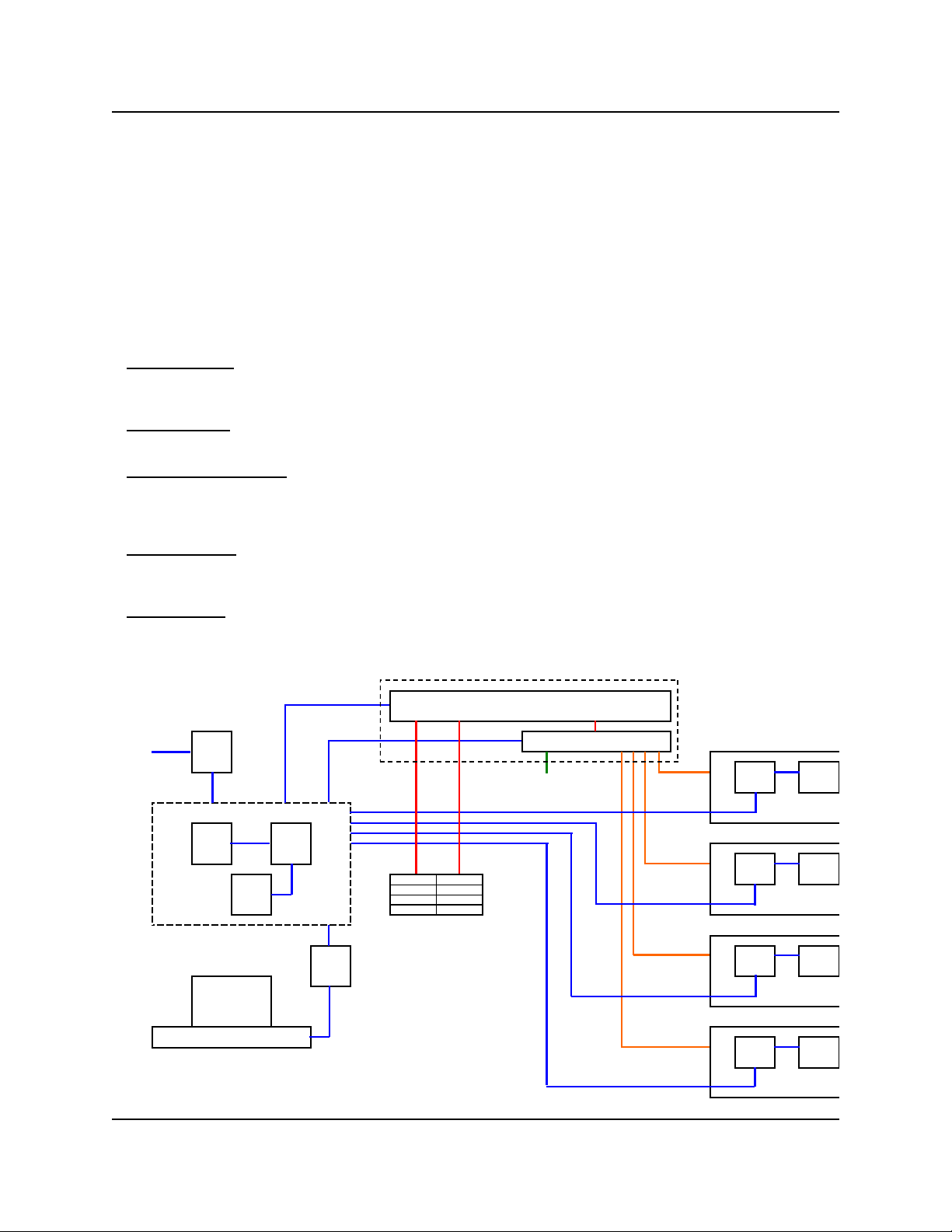
Chem-Trak Jr. (EDP) is a modular system with the Master LFP, CIO Jr and Memory Module in one cabinet, and a
separate power supply. Up to six electric diaphragm pumps (EDP’s) are located in a third cabinet with a separate
flush manifold which includes the manifold block , check valves, one water solenoid, flow switch, and regulator. A
fourth, and separate cabinet, houses the four diverter valves which are used to control delivery to each respective
washer.
A Formula Selector/SIB combination are mounted remotely at each washer. The system can service a maximum of
four washer-extractors. The system can be programmed locally at the Master LFP or globally via a link to Reporter
software using the KCI module. The system stores all programmed features in battery-backed RAM. The battery has
a minimum life of 10 years.
SYSTEM COMPONENTS
Control Module: The Chem-Trak Jr. control module monitors chemical feed requests for up to 4 washers. When a
washer requests a chemical dosage, the control module dispenses the correct amount, then handles the operation
of the flush and transfer to deliver the chemical to the appropriate washer.
Flush Manifold: This area of the system houses the flush manifold and checkvalves. The manifold is where all of
the pumps inject chemical into. The checkvalves prevent cross-contamination of chemicals.
Formula Selector & SIB: Remote formula selector integrates with washer signal inputs and sends chemical
requests to the control module. Each washer has its own formula selector that is used by operators for choosing
wash formulas. When a chemical trigger signal is sent by the washer, the SIB transmits the dosage request to the
control module.
Strobe Alarm(s): The strobe alarm is an audio-visual warning device to alert operators when there is a problem
with the system. When the alarm is activated, there will be various system errors shown on the display of the
control module. The errors are also tracked into memory for later printing a report.
Pump Cabinet: Chem-Trak Jr. uses reliable Knight EDP pumps to deliver up to eight chemicals ranging from .4
GPM to 1.5 GPM.
Pump Cabinet
EDP Chemical Pumps
115/230v
Page 4 of 40 0900960 Rev: B (10/10)

OPERATION
► Normal Chemical Transfer
When the system receives a request for chemical, the following sequence occurs. The diverter valve associated with
the washer requesting chemical is activated and the water flush solenoid valve is also activated. After the flush error
delay time (setup in the programming menus) the system will check the flow switch input. If the switch contact is
closed the system will start the pump and run it for the programmed volume. If the switch contact is open the system
will stop, activate the strobe alarm, and display ―FE‖ (indicating flush error) on the formula selector for each washer.
At the end of the pump run time the water flush solenoid will continue to operate for the flush time and transfer time
programmed in the setup. This time should be set long enough to ensure all chemical is flushed through the system
and to the washer. If the flow switch contacts open (for longer than the flush error delay) at any time during the flush
cycle, the system will shut down with a flush error as described above.
If a specific flush time is programmed for the pump that is running, the system will add this additional time to the
normal flush time. If the Halt with Injection feature is used, the Chem-Trak Jr. SIB will hold the washer during the
entire process described above.
► Multiple Chemical Requests (one machine)
If multiple chemicals have been requested by one machine, then the following sequence occurs. If the Flush Between
feature is used, then the system will activate the programmed flush time between each pump activation to provide a
barrier of water between non-compatible chemicals. This sequence continues until all requested products have been
dispensed. The system then follows the transfer sequence described in the section above to push all chemical and
water to the washer. The maximum number of pumps that can run simultaneously is three total.
► Multiple Chemical Requests (multiple machines)
If a washer calls for product while the system is active servicing another washer then the system puts the request in a
queue. The washer interface puts the washer into halt mode (if the Chem-Trak Jr. SIB is interfaced with the washer’s
controls) to ensure the chemical does not miss injection to the correct wash cycle step. When the system is ready to
process the request, washer halt is de-activated and a normal transfer sequence will begin.
► Multiple Injection Levels
Using multiple volume levels allows a pump to dispense different amounts of chemical upon subsequent signals. For
example, on a particular formula, pump 1 could pump 8 ounces of chemical the first time it is signaled, and pump 1
could pump 12 ounces of chemical the second time it is signaled. Up to three volume levels (max) are available per
pump.
Multiple volume levels can be used for any pump on any formula, except the load count pump. Only level 1 can be
programmed on the load count pump (or any other pumps that are signaled at the same time as the load count
pump).
After the load count pump has been triggered (to end the previous formula) the next signal to a pump will dispense
Level 1 amounts. The next washer signal to the same pump will be Level 2 if there is a run or delay time
programmed. If no time is programmed, it will skip Level 2 and go to Level 3. If there is no time programmed on Level
3, it will disregard Level 3 and dispense Level 1 amounts again.
By using run or delay times on the different levels, you can have a plurality of chemical formulas using multiple
signals from the same card or microprocessor. To ―use up‖ a level and NOT dispense product, simply program a ―0"
volume and a ‖1" second delay time for that level.
0900960 Rev: B (10/10) Page 5 of 40

PRE-INSTALLATION
Before installing Chem-Trak Jr., you should survey the installation site thoroughly to determine materials and tools
that will be needed. You may wish to use the specifications in the front section of this manual as reference. At the
very least, your site survey should included the following.
Locate a 115 or 230 VAC power source.
Locate a water source and nearby drain.
Plan to place the unit in view of the washer line so the operators can see alarms, and also where there is enough
room for chemical containers.
Plan your delivery lines and the easiest route to each machine for tubing and wiring of the formula selectors.
Check to make sure that all functions of the laundry machine are operating properly (i.e. drain valve, hot/cold water
solenoids, flush down valves, water level switch, card reader or timer, and machine motor).
Familiarize yourself with all applicable safety, electrical, and plumbing codes.
Measure the distance from the chemical supply containers to where the chemical pumps will be mounted.
Measure the distance from where the system will be mounted to each respective washmachine.
Make a list of all parts, electrical and plumbing, so you will have everything you need to complete the install.
INSTALLATION
(1) Choose a location as close as possible to the chemical supply and no more than 10 ft above chemical
containers. Mount the joggle bracket to the wall using appropriate hardware.
(2) Hang the system on the joggle bracket. There is a 1/4‖ hole on the lower back wall of the control module cabinet
to allow the unit to be secured to the wall using appropriate hardware.
(3) Install braided tubing between the discharge (left) side of the pump and the corresponding port on the flush
manifold. Use stainless steel hose clamps and barb fittings to secure braided tubing to pump.
(4) Install braided tubing between the suction (right) side of the pump and the barb fitting on the PVC pickup tube.
Use stainless steel hose clamps and barb fittings to secure braided tubing to the pickup tube.
(5) Insert pickup line into appropriate chemical container.
(6) Run a drain line from the top port on the 3-way valve to floor drain or nearest trough. The drain line is used to
divert water flow away from manifold (by using the 3-way valve) to relieve pressure from the manifold for
maintenance.
(7) Mount the power supply box and connect to the terminals on the lower right corner of the CIO board in the
control module cabinet (see wiring diagram).
(8) Connect each pump signal input on the SSI circuit board to corresponding terminals on the CIO circuit board
(see wiring diagram).
(9) Connect power to the SSI circuit board from the Power Supply Unit (see wiring diagram). Follow local wiring
codes — this will typically require the use of conduit.
(10) Connect main power input to the power supply box using suitable conduit.
(11) Run water supply ensuring adequate pressure. Warm water is recommended for best results.
(12) If using SA-12 strobe alarms, mount and wire to the appropriate terminals on the CIO.
(13) Connect multi-link wires for each system if more than one system will be used.
(14) Route the delivery lines from the diverter control to each respective washer.
Page 6 of 40 0900960 Rev: B (10/10)

► Formula Selector’s and SIB’s
One formula selector and one SIB are required for each washer that the Chem-Trak Jr. will feed. Be sure to connect
the formula selector to the appropriate remote terminals on the CIO board (the ―remote‖ numbers shown on the CIO
board correspond to the washer number). Perform the steps below for each washer.
(1) Ensure that main power to the Chem-Trak Jr. is off.
(2) Mount the formula selector to the washer using a mounting bracket or dual-lock fastening strips.
(3) Route the formula selector cable to the unit and connect to the CIO board in the control box (avoid running the
cable near any source of electrical noise such as high voltage AC lines, motor contactors, etc).
(4) Mount the SIB near the washer’s signal source using dual-lock fastening strips. If desired, the SIB can be
mounted right inside the washer’s control box.
(5) Connect the SIB to the formula selector using 3 conductor cable.
(6) Check the signal voltage output from the laundry machine. Measure the voltage between control signal and
signal common, NOT control signal and case ground.
(7) Ensure that power to the washer is off.
(8) Connect signal wires to SIB per wire colors on the label of the SIB. If split commons are required, a resistor can
be removed inside the SIB to allow use of 2 different signal commons (see page 8 for details).
(9) If Auto Formula Select will be used, be sure to choose the correct input on the SIB for the application (see page
21 for details).
(10) If the washer hold feature will be used, the Chem-Trak Jr. SIB must be properly interfaced with the washer to
permit the SIB to pause the washer if other washers are requesting chemical. See the Washer Hold section (on
page 10) for more details.
► Remaining Steps
(1) Power the system up.
(2) Program the system either at the main keypad, or by uploading a setup (HEX) file using WinReporter.
(3) Prime and calibrate each chemical pump at the main keypad according to the instructions in the programming
section of this manual.
(4) After the system is programmed, observe the operation to ensure all washers are getting chemical and operating
properly. The washer hold feature can be used to ensure proper delivery to each washer.
(5) Check for any water leaks and verify that water pressure is adequate to flush chemical to each washer. Check to
ensure that the flush time and transfer time settings are adequate.
(6) Fully train the staff to service and recognize alarms and how to satisfy them. As well as how to maintain the
system (i.e. pump inspection, check valves, etc).
0900960 Rev: B (10/10) Page 7 of 40
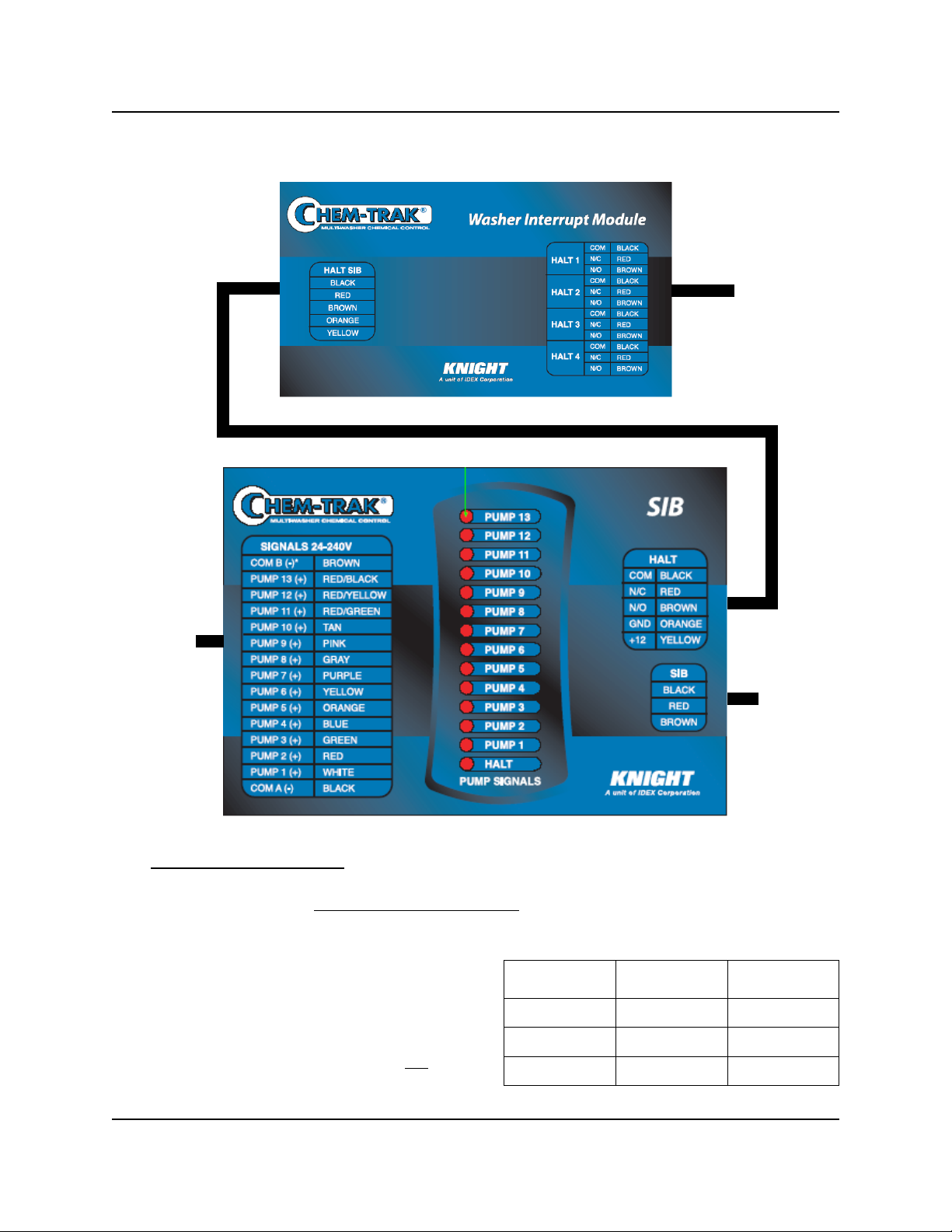
SIB & INTERRUPT MODULES
CONNECTS
TO WASHER’S
CONTROLS
CONNECTS
TO WASHER’S
SIGNALS
CONNECTS
TO FORMULA
SELECTOR
► Splitting Signal Commons
If you have one signal common (typical) connect it to ―COM A‖ only. If you have two signal commons, you will need to
remove a resistor inside the SIB before connecting common wires! Once the resistor is removed, you can then use
COM A and COM B for different groups of signals shown in the table. Shut off all power sources before continuing.
(1) Remove screws from the bottom of the SIB to open it.
(2) Locate the three resistors marked R15, R14, and R13,
on the left side of the module (each resistor has a single
black band to identify it).
(3) Cut and remove the resistor that will ―split‖ the commons
between the desired pumps. Remove only one resistor.
(4) Close the module and replace screws when finished.
CUT RESISTOR
R15 1 — 2 3 — 13
R14 1 — 3 4 — 13
R13 1 — 5 6 — 13
TO USE COM A
FOR PUMPS
AND COM B
FOR PUMPS
Page 8 of 40 0900960 Rev: B (10/10)
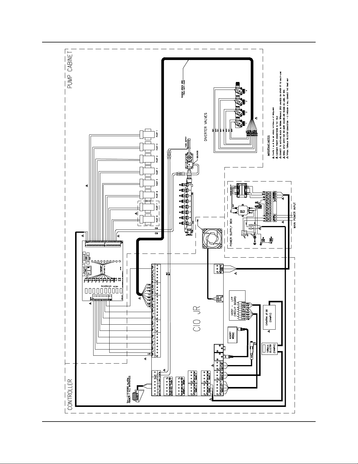
WIRING DIAGRAM
0900960 Rev: B (10/10) Page 9 of 40
WASHER HOLD FUNCTION
CHEM-TRAK SIB
WASHER TIMER MOTOR
115 VAC (EXAMPLE)
RELAY WIRED FOR
NORMALLY CLOSED
OPERATION
The Chem-Trak Jr. System has two halt (washer hold) modes that pause the washer operation to allow sufficient time
for chemical injection to reach the machine. There is also a ―maintenance hold‖ function that halts the washer
operation and puts the chemical request in the queue for later delivery. Below is a brief overview of the purpose for
each halt mode. More information can be found in the Operation section of this manual, and information on
maintenance hold can be found in the Programming section of this manual.
Normal Hold: The washer is halted if its requesting chemical feed while the system is busy feeding other washers.
Halt With Injection: Operates same as above (normal hold) but will additionally halt the washer during its own
chemical injection.
Maintenance Hold: This function is used while performing maintenance on the system, and must be enabled at
the host control panel. While the system is on maintenance hold, any washers that request chemical will be put on
hold and the feed request will be added to the queue to be delivered later when finished with maintenance hold.
When any of the hold functions are activated, a relay on the Chem-Trak SIB is energized. This relay can be wired
normally open or normally closed depending on the type of washer (examples following). The relay causes the
washer to halt until the relay is de-energized, then allowing the washer to resume normal operation.
An additional halt module can be wired into the Chem-Trak SIB for applications that require more than one relay
(example following). The halt module has four relays that activate simultaneously with the relay on the SIB to expand
the washer hold capabilities of the Chem-Trak Jr.
Before attempting to wire the machine for the washer hold function, make sure that you have a wiring diagram of the
machine’s controls, and that you fully understand how to perform the necessary electrical changes. Also consider
how this feature may affect the wash cycle operation.
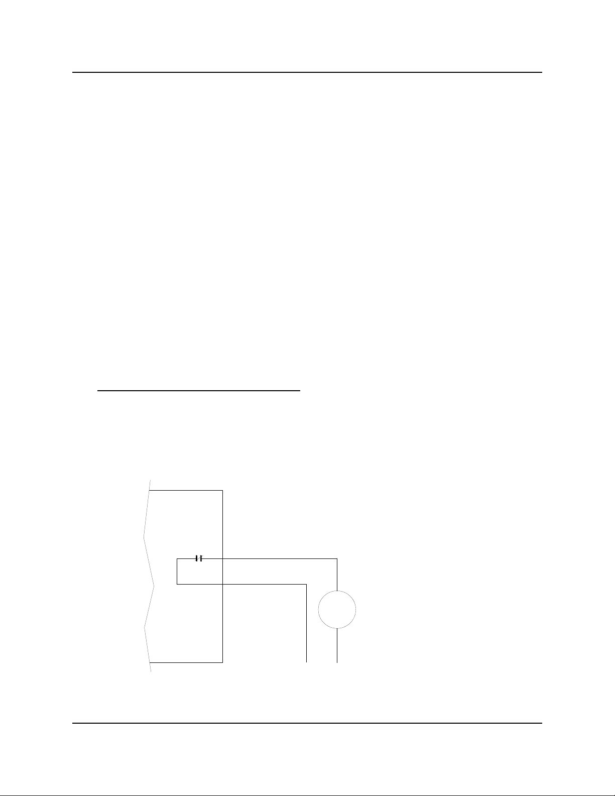
► Fixed Timer or Card Reader Type Washers
The key to halting a fixed timer or card reader machine is to interrupt the motor that controls the timer or card reader
mechanism. Wire the timer motor to the Chem-Trak Jr. SIB using the normally closed (N/C) configuration as shown in
the diagram below. When the halt feature is active, the relay will open the circuit and thereby pause the washer.
Page 10 of 40 0900960 Rev: B (10/10)
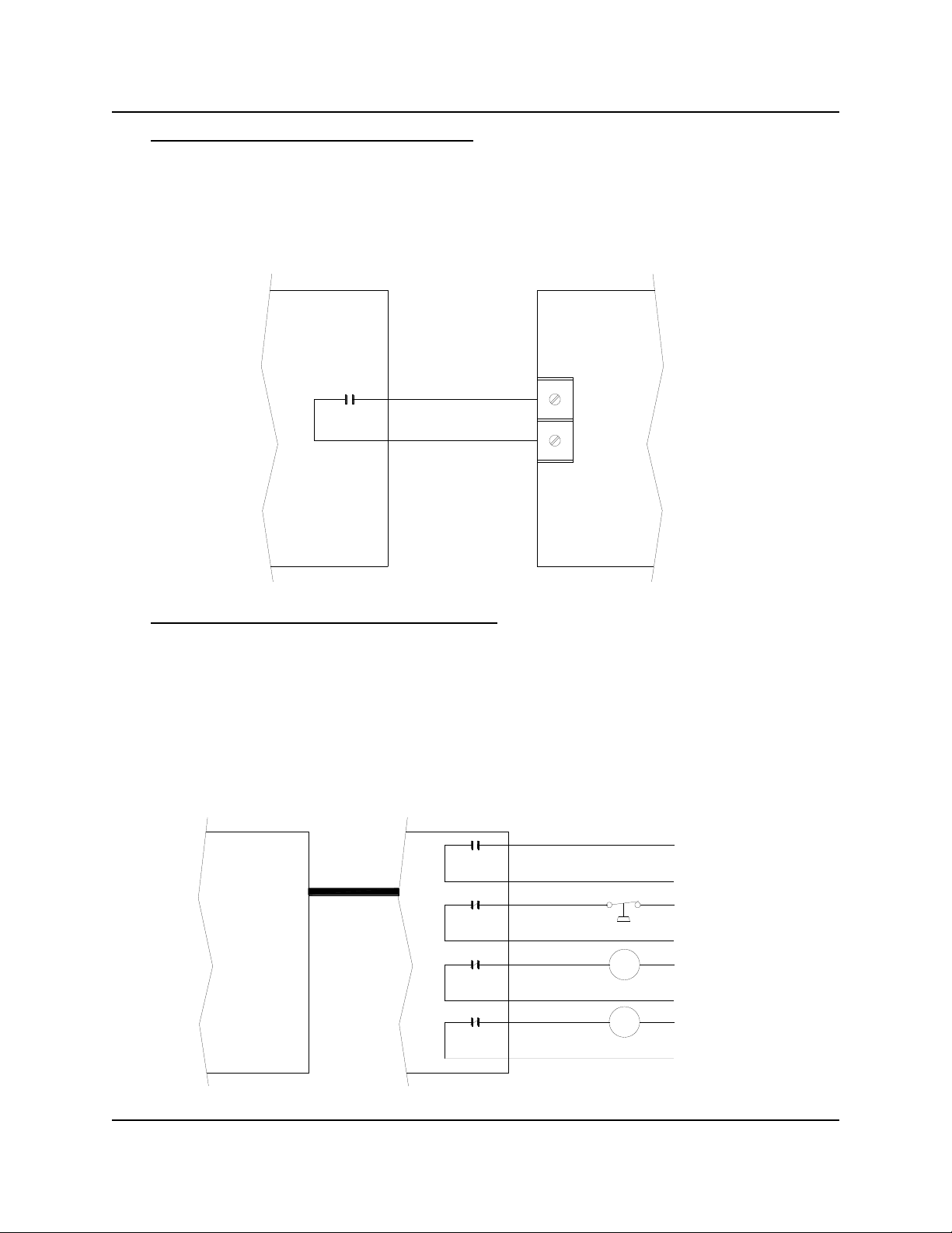
► Microprocessor Washer with Pause Control
CHEM-TRAK SIB WASHER PAUSE CONTROL
RELAY WIRED FOR
NORMALLY OPEN
OPERATION
HALT MODULE
RELAYS WIRED FOR
NORMALLY CLOSED
OPERATION
C
H
COLD WATER SOLENOID
HOT WATER SOLENOID
WATER LEVEL SENSOR
NOT USED IN THIS EXAMPLE
CHEM-TRAK SIB
5-CONDUCTOR CABLE
If the washer is microprocessor controlled, check to see if it has a designated input for connecting an external pause
device that operates with ―dry contacts‖ (such as a toggle switch). If the machine has such an input, then the relay on
the Chem-Trak SIB can be connected using the normally open (N/O) configuration as shown in the diagram below.
When the halt feature is active, the relay will close the circuit and thereby pause the washer.
► Microprocessor Washer without Pause Control
If the washer is microprocessor controlled but does not have a designated input for connecting an external pause
device, then other circuits on the machine will have to be interrupted using the halt module. The most common
approach is to wire the machine’s water level sensor, hot water fill solenoid, and cold water fill solenoid to the
normally closed contacts on the halt module as shown in the diagram below. When the halt feature is active, the
relays will open the circuits and thereby pause the washer.
NOTE: When the halt module is inter-connected to the Chem-Trak SIB, then the relay on the SIB can no longer be
used. Only use the relays on the halt module for this type of setup.
0900960 Rev: B (10/10) Page 11 of 40
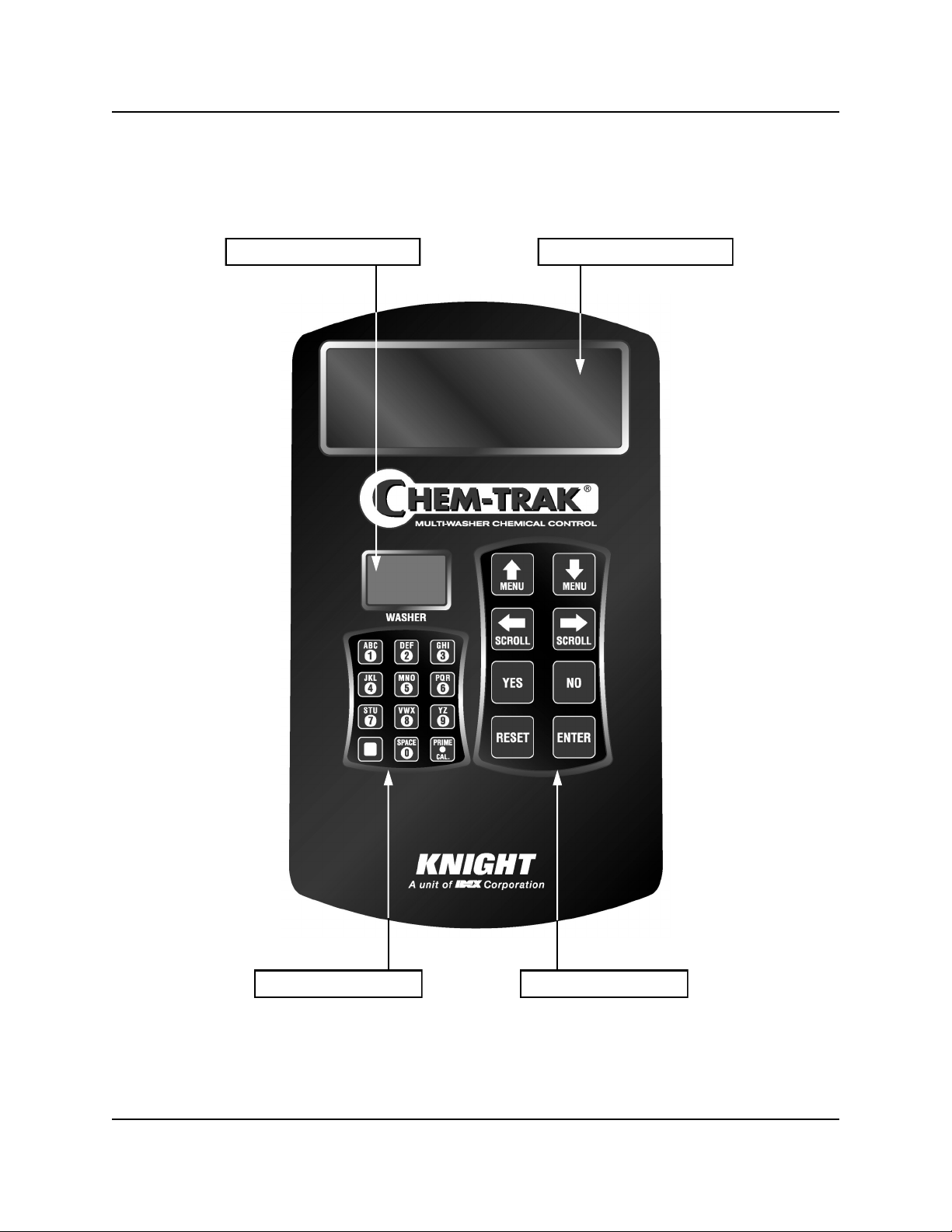
KEYPAD DIAGRAM
PROGRAMMING DISPLAY WASHER NUMBER DISPLAY
ALPHANUMERIC KEYPAD PROGRAMMING KEYPAD
Page 12 of 40 0900960 Rev: B (10/10)
 Loading...