

Knight Equipment APC-200 Installation Manual

APC-200 INSTRUCTION MANUAL
INTRODUCTION
The Liquidtrol Air Pump Control is designed to interface an ILCS-6900
Dispensing System to one or two optional Air Operated Double Diaphragm
Pumps. Air pumps are generally used as an alternative to peristaltic pumps
where feed rates in excess of three gallons per minute are required.
The APC-200 unit is installed in close proximity to the ILCS-6900 and
connects to the air pumps using 3/8” air line. Air pumps should be mounted
near the chemical source and push chemical to the point of use.
THEORY OF OPERATION
The APC-200 Liquidtrol Air Pump Control includes one or two air solenoid
valves for operating one or two Air Operated Double Diaphragm Pumps.
Built-in pressure regulators provide control of the air pump feed rate and
allow accurate calibration of the chemical volumes. An air filter prevents
“dirty” or “wet” air from contaminating the air solenoid valve. Adjustments for
the pressure regulator are located in the APC-200 cabinet to discourage
tampering by unauthorized users.
INSTALLATION
See diagrams on the following page for illustration of the steps below.
(1) Mount unit on a wall in a location that is near the ILCS-6900 System.
(2) Connect incoming air source to the inlet fitting using 3/8“ poly tubing.
Max recommended pressure is 150 PSI.
(3) Connect the outlet fitting(s) from the air solenoid valves to the air pump
inlet port using 3/8” poly tubing.
(4) Connect the solenoid(s) to the desired output circuits on the ILCS pump
output board using conduit and wiring that complies with all applicable
electrical codes. The solenoids are connected to a wiring barrier inside
the APC control box for quick and easy connection.
(5) Use of an air-operated 2-way valve is recommended for installations
where siphoning can occur. See part numbers to the lower right.
OPERATION / START-UP
Consult Air Pump operation manual for mfr’s operating specifications.
(1) Manually activate pump(s) using the prime button(s) on the ILCS pump
board. Priming a “dry” pump m ay require you flood the pump suction
with water. Suction line should be no longer than 10 feet (3 meters).
(2) The air pump will typically be easier to prime when running at a slower
speed. The speed and volume delivery of the pump can be controlled
by turning the regulator clockwise to increase pressure and counterclockwise to decrease pressure.
(3) Once the pump is primed, adjust the air pressure as needed and
calibrate the ILCS-6900 per the directions in the ILCS programming
manual (Dispenser Programming Routines menu).
Knight Air-Operated 2-Way
Valves can be ordered using the
following part numbers:
P/N 1600954 — for 1” ID line
P/N 1600955 — for 1/2” ID line
0900957 Rev: B (08/02) Page1of4
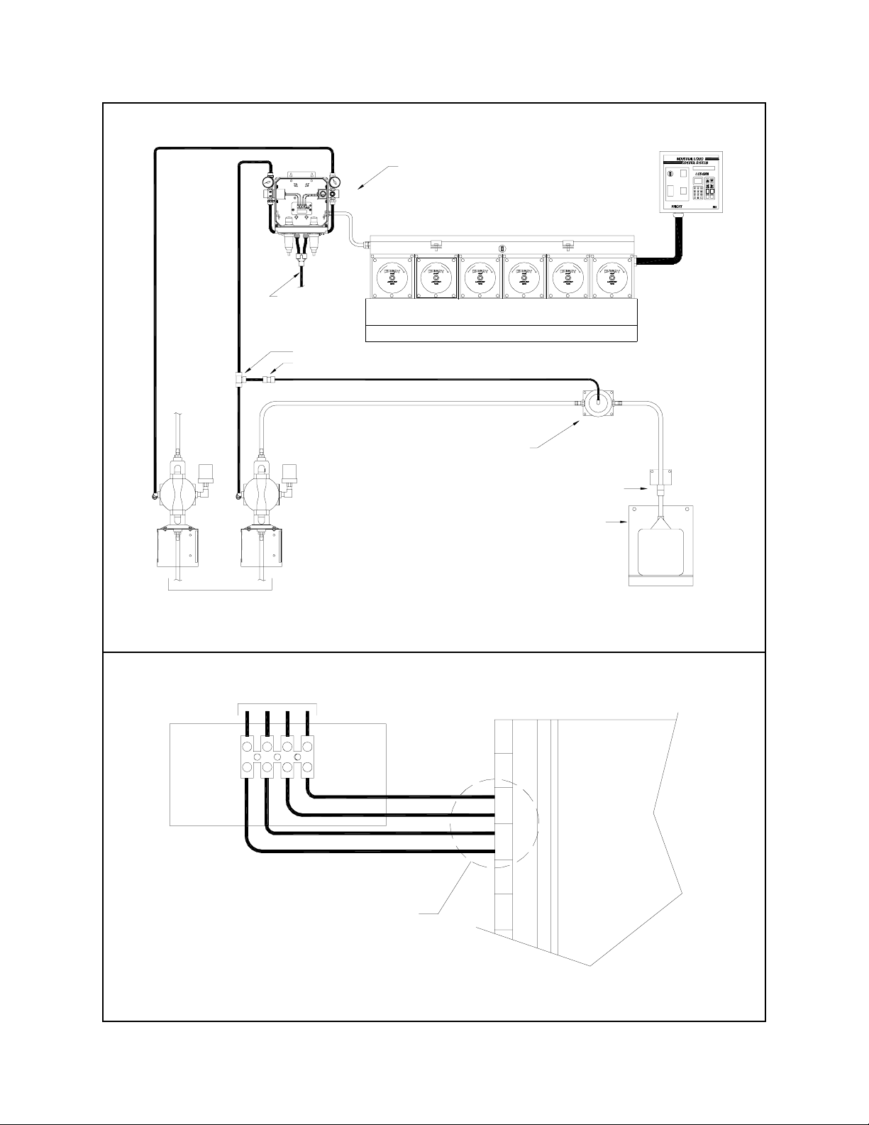
INSTALLATION AND WIRING DIAGRAMS
TO CHEMICAL TANKS
APC-200 AIR PUMP CONTROL
O
INCOMING
AIR SOURCE
W
L
F
W
O
L
F
QUICK-CONNECT 3/8" TEE FITTING (P/N 0600605)
QUICK-CONNECT 3/8" - 1/4" REDUCER (P/N 0600609)
EXAMPLE OF USING AIR OPERATED
2-WAY VALVE FOR APPLICATIONS
WHERE SIPHONING CAN OCCUR
NOTE: AIR PUMPS CAN BE LOCATED
REMOTELY AND "PUSH" CHEMICAL TO
THE POINT OF DISPENSE, HOWEVER A
SLIGHT AIR PRESSURE DROP CAN OCCUR
THE FARTHER THE PUMPS ARE FROM
THE APC-200. THIS MAY REQUIRE AN
ADJUSTMENT TO THE AIR PRESSURE TO
GET THE DESIRED OUTPUT FLOW RATE.
I.L.C.S.
DATAMANAG EMENTSYSTEM
CYCLE
ON/OFF
START
MAIN
POWER
FORMULA
WATER
GHIDEFABC
2
3
1
MNO
JKL
PQR
YES
5
6
4
VWX
STU
YZ
8
7
9
ENTERNORESET
P
R
I
M
E
SPACE
H
B
A
T
C
0
C
O
U
N
T
C
A
L
.
O
W
O
W
O
L
F
L
F
W
L
F
W
O
L
F
SPOUT
CONTAINER
SHELF
TO AIR SOLENOIDS
PUMP OUTPUTS #7 AND #8 ARE
SHOWNINTHISEXAMPLE.THIS
IS A TYPICAL APPLICATION,
HOWEVERTHE APC-200CAN BE
WIRED TO ANY AVAILABLE PUMP
OUTPUTS ON THE CONTROL BOARD.
CUTAWAY VIEW OF ILCS
PUMP OUTPUT BOARD (POB)
P
#
U
10
M
P
P
#
U
9
M
P
P
#
U
8
M
P
P
#
U
7
M
P
P
#
U
6
M
P
P
#
U
5
M
P
ILCS-APC-INSTALL/0 82102
Page2of4 0900957 Rev: B (08/02)
 Loading...