


YKFES530ESS0
KitchenAid YKFES530ESS0, YKFEG510ESS3, YKFEG510ESS1, YKFEG510ESS0, YKFEG500ESS3 Installation Guide
...
INSTALLATION INSTRUCTIONS
30" (76.2 CM) FREESTANDING ELECTRIC RANGES
INSTRUCTIONS D’INSTALLATION DES CUISINIÈRES
ÉLECTRIQUES AUTOPORTANTES DE 30" (76,2 CM)
Table of Contents/Table des matières
RANGE SAFETY .............................................................................2
INSTALLATION REQUIREMENTS................................................3
Tools and Parts ............................................................................3
Location Requirements................................................................3
Electrical Requirements ...............................................................4
INSTALLATION INSTRUCTIONS..................................................4
Unpack Range..............................................................................4
Install Anti-Tip Bracket.................................................................5
Level Range..................................................................................6
Verify Anti-Tip Bracket Is Installed and Engaged ........................6
Warming Drawer or Premium Storage Drawer............................7
Storage Drawer ............................................................................7
Oven Door ....................................................................................8
Complete Installation ...................................................................8
Moving the Range........................................................................9
SÉCURITÉ DE LA CUISINIÈRE ...................................................10
EXIGENCES D'INSTALLATION...................................................11
Outillage et pièces......................................................................11
Exigences d'emplacement.........................................................11
Spécifications électriques ..........................................................12
INSTRUCTIONS D'INSTALLATION.............................................13
Déballage de la cuisinière ..........................................................13
Installation de la bride antibasculement ....................................13
Réglage de l'aplomb de la cuisinière.........................................14
Vérifier que la bride antibasculement est
bien installée et engagée............................................................15
Tiroir-réchaud ou tiroir de remisage de qualité supérieure .......15
Tiroir de remisage.......................................................................16
Porte du four...............................................................................16
Achever l’installation ..................................................................17
Déplacement de la cuisinière.....................................................17
IMPORTANT:
Save for local electrical inspector's use.
IMPORTANT :
À conserver pour consultation par l'inspecteur local des installations électriques.
W10694024C
2
RANGE SAFETY
You can be killed or seriously injured if you don't immediately
You
can be killed or seriously injured if you don't
follow
All safety messages will tell you what the potential hazard is, tell you how to reduce the chance of injury, and tell you what can
happen if the instructions are not followed.
Your safety and the safety of others are very important.
We have provided many important safety messages in this manual and on your appliance. Always read and obey all safety
messages.
This is the safety alert symbol.
This symbol alerts you to potential hazards that can kill or hurt you and others.
All safety messages will follow the safety alert symbol and either the word “DANGER” or “WARNING.”
These words mean:
follow instructions.
instructions.
DANGER
WARNING
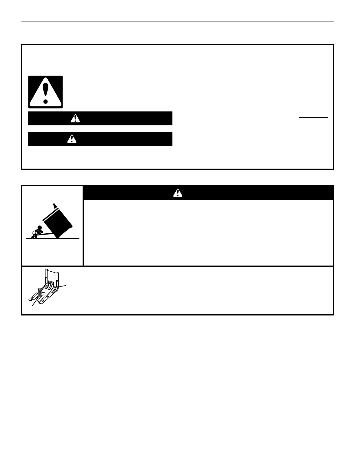
Tip Over Hazard
A child or adult can tip the range and be killed.
Install anti-tip bracket to floor or wall per installation instructions.
Slide range back so rear range foot is engaged in the slot of the anti-tip bracket.
Re-engage anti-tip bracket if range is moved.
Do not operate range without anti-tip bracket installed and engaged.
Failure to follow these instructions can result in death or serious burns to children and adults.
Anti-Tip
Bracket
To verify the anti-tip bracket is installed and engaged:
• Slide range forward.
• Look for the anti-tip bracket securely attached to floor or wall.
• Slide range back so rear range foot is under anti-tip bracket.
• See installation instructions for details.
Range Foot
WARNING
3
INSTALLATION REQUIREMENTS
Tools and Parts
Gather the required tools and parts before starting installation.
Read and follow the instructions provided with any tools listed here.
Tools Needed
Parts Supplied
Check that all parts are included.
■ Anti-tip bracket must be securely mounted to floor or wall.
Thickness of flooring may require longer screws to anchor
bracket to floor.
Parts Needed
Check local codes. Check existing electrical supply. See
“Electrical Requirements” section.
It is recommended that all electrical connections be made by a
licensed, qualified electrical installer.
Location Requirements
IMPORTANT: Observe all governing codes and ordinances.
■ It is the installer’s responsibility to comply with installation
clearances specified on the model/serial/rating plate. The
model/serial/rating plate is located on the frame behind a top
corner of the door or on either side of the drawer.
■ To eliminate the risk of burns or fire by reaching over heated
surface units, cabinet storage space located above the
surface units should be avoided. If cabinet storage is to be
provided, the risk can be reduced by installing a range hood
that projects horizontally a minimum of 5" (12.7 cm) beyond
the bottom of the cabinets.
■ Cabinet opening dimensions that are shown must be used.
Given dimensions are minimum clearances.
■ The anti-tip bracket must be installed. To install the anti-tip
bracket shipped with the range, see “Install Anti-Tip Bracket”
section.
■ Grounded electrical supply is required. See “Electrical
Requirements” section.
IMPORTANT: To avoid damage to your cabinets, check with your
builder or cabinet supplier to make sure that the materials used
will not discolor, delaminate or sustain other damage. This oven
has been designed in accordance with the requirements of UL
and CSA International and complies with the maximum allowable
wood cabinet temperatures of 194°F (90°C).
Mobile Home - Additional Installation Requirements
The installation of this range must conform to the Manufactured
Home Construction and Safety Standard, Title 24 CFR, Part 3280
(formerly the Federal Standard for Mobile Home Construction
and Safety, Title 24, HUD Part 280). When such standard is not
applicable, use the Standard for Manufactured Home
Installations, ANSI A225.1/NFPA 501A or with local codes.
In Canada, the installation of this range must conform with the
current standards CAN/CSA-Z240-latest edition, or with local
codes.
Mobile home installations require:
■ When this range is installed in a mobile home, it must be
secured according to the instructions in this document.
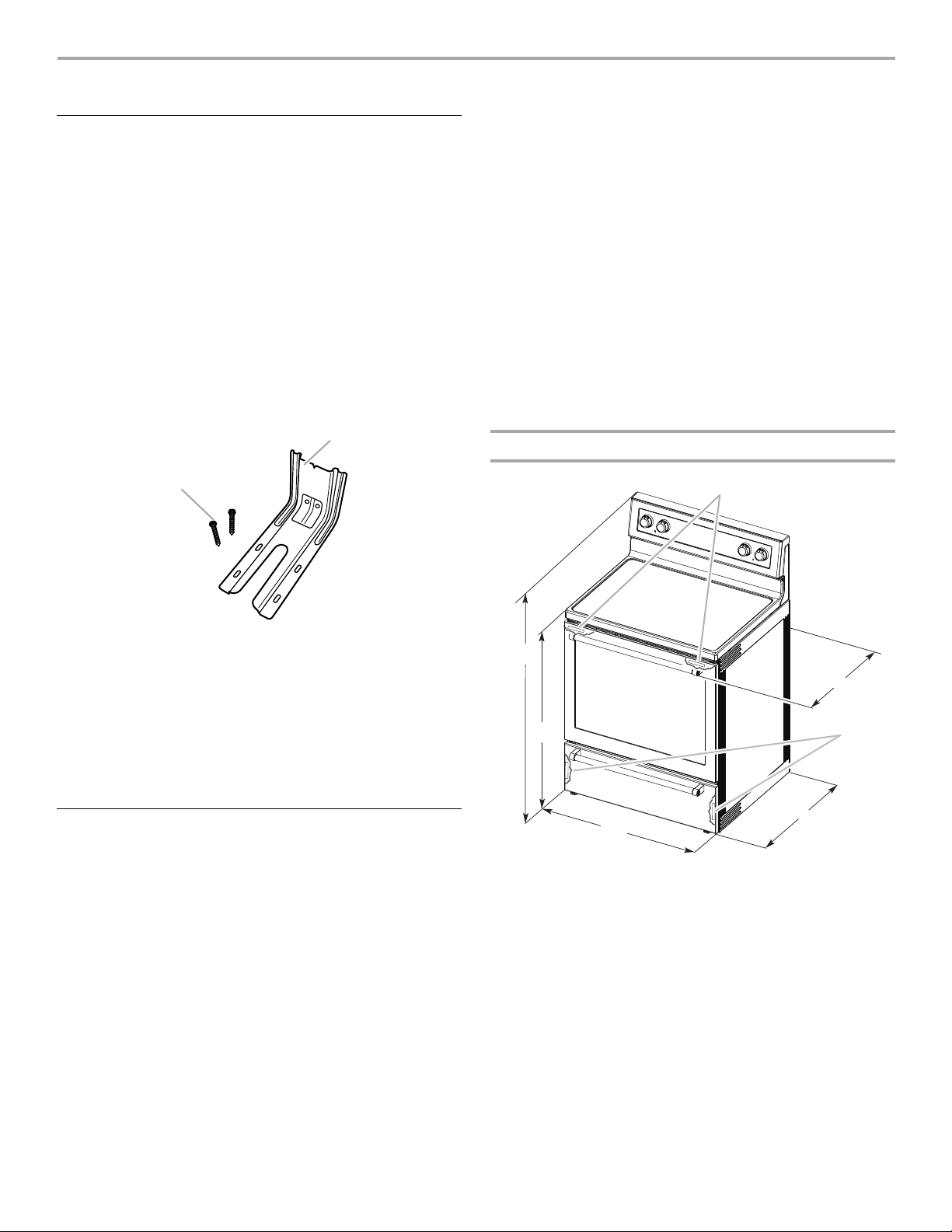
Product Dimensions
IMPORTANT: Range must be level after installation. Follow the
instructions in the “Level Range” section. Using the cooktop as a
reference for leveling the range is not recommended.
*Range can be raised approximately 1" (2.5 cm) by adjusting
the leveling legs.
**Front of door and drawer may extend further forward
depending on styling.
■ Tape m e a s ure
■ Flat-blade screwdriver
■ Phillips screwdriver
■ Level
■ Hammer
■ Hand or electric drill
■ Wrench or pliers
■ Marker or pencil
■ Masking tape
■ ¼" drive ratchet
■ ¼" nut driver
■ ³⁄₈" and ⁵⁄₁₆" nut driver
■ ¹⁄₈" (3.2 mm) drill bit (for
wood floors)
A. Anti-tip bracket
B. #12 x 1
⁵⁄₈
" screws (2)
A
B
A. 27
³⁄₄
" (70.5 cm) max. depth with handle
B. 47
¹⁄₈
" (119.7 cm) overall height (max.) with leveling legs
screwed in all the way*
C. 36" (91.4 cm) cooktop height (max.) with leveling legs screwed
in all the way*
D. 29
⁷⁄₈
" (75.9 cm) width
E. 25
⁵⁄₁₆
" (64.3 cm) depth - back of range to front of cooktop**
F. Model/serial/rating plate (located on the frame behind a top
corner of the door or on either side of the drawer)
A
E
D
C
B
F
F
4
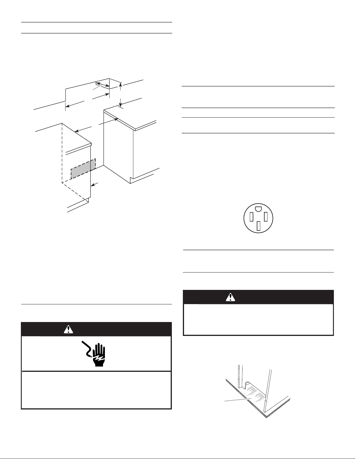
Cabinet Dimensions
Cabinet opening dimensions shown are for 25" (64.0 cm)
countertop depth, 24" (61.0 cm) base cabinet depth and
36" (91.4 cm) countertop height.
IMPORTANT: If installing a range hood or microwave hood
combination above the range, follow the range hood or
microwave hood combination installation instructions for
dimensional clearances above the cooktop surface.
*NOTE: 24" (61.0 cm) minimum when bottom of wood or metal
cabinet is covered by not less than ¹⁄₄" (0.64 cm) flame retardant
millboard covered with not less than No. 28 MSG sheet steel,
0.015" (0.4 mm) stainless steel, 0.024" (0.6 mm) aluminum or
0.020" (0.5 mm) copper.
30" (76.2 cm) minimum clearance between the top of the cooking
platform and the bottom of an uncovered wood or metal cabinet.
Electrical Requirements
If codes permit and a separate ground wire is used, it is
recommended that a qualified electrical installer determine that
the ground path is adequate and wire gauge are in accordance
with local codes.
Be sure that the electrical connection and wire size are adequate
and in conformance with CSA Standard C22.1, Canadian
Electrical Code, Part 1 - latest edition, and all local codes and
ordinances.
A copy of the above code standards can be obtained from:
Canadian Standards Association
178 Rexdale Blvd.
Toronto, ON M9W 1R3 CANADA
■ Check with a qualified electrical installer if you are not sure
the range is properly grounded.
*The NEC calculated load is less than the total connected load
■ A time-delay fuse or circuit breaker is recommended.
■ This range is equipped with a CSA International Certified
Power Cord intended to be plugged into a standard 14-50R
wall receptacle. Be sure the wall receptacle is within reach of
range’s final location.
■ Do not use an extension cord.
INSTALLATION INSTRUCTIONS
Unpack Range
1. Remove shipping materials, tape and film from range.
2. Remove oven racks and parts package from inside oven.
3. Do not remove the shipping base at this time.
A
B
D
F
E
C
WARNING
Electrical Shock Hazard
Electrically ground range.
Failure to do so can result in death, fire, or
electrical shock.
Range Rating* Specified Rating of
Power Supply Cord Kit
and Circuit Protection
120/240 Volts 120/208 Volts Amps
8.8 - 16.5 KW
16.6 - 22.5 KW
7.8 - 12.5 KW
12.6 - 18.5 KW
40 or 50**
50
A. Shipping base
WARNING
Excessive Weight Hazard
Use two or more people to move and install range.
Failure to do so can result in back or other injury.
A
A. 13" (33.0 cm) max. upper cabinet depth
B. 30" (76.2 cm) min. opening width
C. For minimum clearance to top of cooktop, see NOTE*.
D. 30" (76.2 cm) min. opening width
E. Outlet - 8" to 22" (20.3 cm to 55.9 cm) from either cabine
t,
7" (17.8 cm) max. from floor
F. Cabinet door or hinges should not extend into the cutout.
listed on the model/serial/rating plate.
**If connecting to a 50 amp circuit, use a 50 amp rated cord with
kit. For 50 amp rated cord kits, use kits that specify use with a
nominal 1³⁄₈" (34.9 mm) diameter connection opening.
5
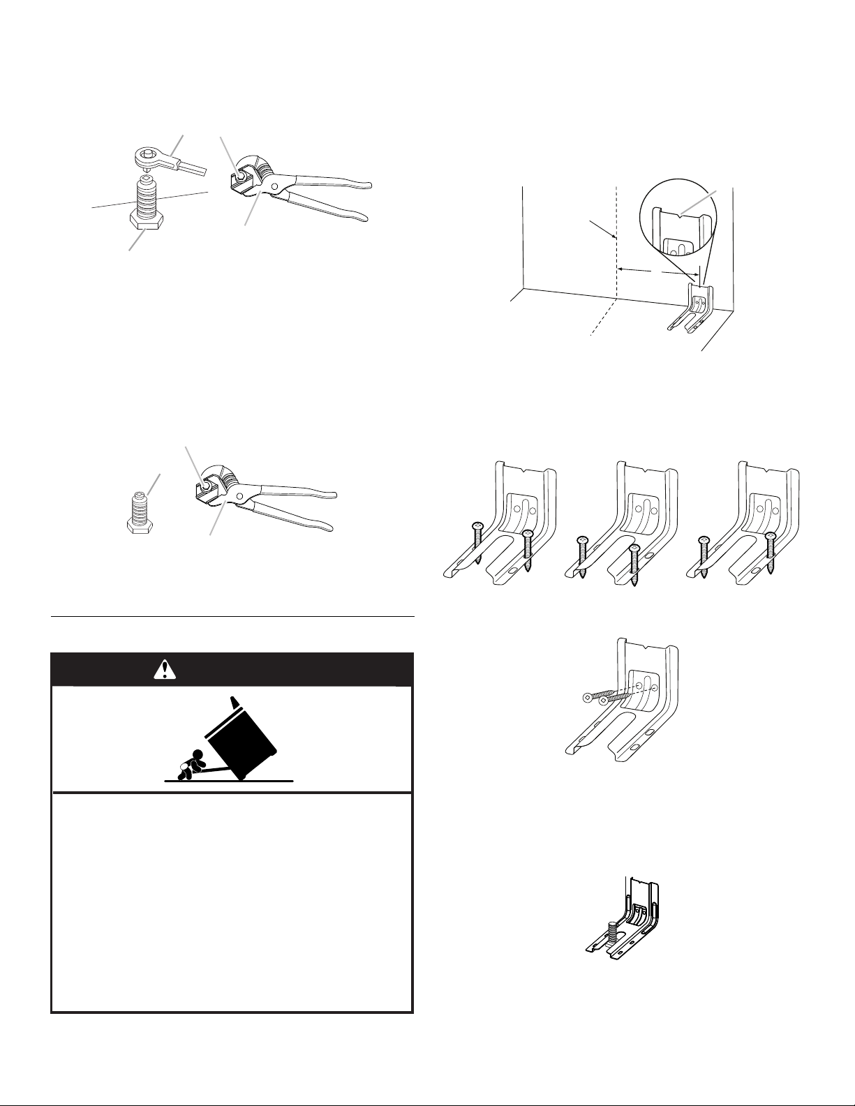
4. On Ranges Equipped with a Storage Drawer:
Remove the storage drawer. See the “Storage Drawer”
section. Use a ¼" drive ratchet to lower the rear leveling legs
one-half turn. Use a wrench or pliers to lower front leveling
legs one-half turn.
On Ranges Equipped with a Warming Drawer or Premium
Storage Drawer:
On ranges equipped with a warming drawer or premium
storage drawer, the rear leveling legs cannot be accessed by
removing the warming drawer or premium storage drawer. It
will be necessary to adjust the rear leveling legs from outside
the range. Use wrench or pliers to lower the front and rear
leveling legs one-half turn.
Install Anti-Tip Bracket
1. Remove the anti-tip bracket from where it is taped inside the
storage drawer or warming drawer.
2. Determine which mounting method to use: floor or wall.
If you have a stone or masonry floor, you can use the wall
mounting method. If you are installing the range in a mobile
home, you must secure the range to the floor.
3. Determine and mark centerline of the cutout space. The
mounting bracket can be installed on either the left-hand side
or right-hand side of the cutout. Position mounting bracket
against the wall in the cutout so that the V-notch of the
bracket is 12⁹⁄₁₆" (31.9 cm) from centerline as shown.
4. Drill two ¹⁄₈" (3 mm) holes that correspond to the bracket
holes of the determined mounting method. See the following
illustrations.
Floor Mounting
Wall Mounting
5. Using two #12 x 1⁵⁄₈" Phillips-head screws provided, mount
anti-tip bracket to the wall or floor.
6. Move range close enough to opening to allow for final
electrical connections. Remove shipping base, cardboard or
hardboard from under range.
7. Move range into its final location, making sure rear leveling
leg slides into anti-tip bracket.
A. ¼" drive ratchet
B. Rear leveling leg
C. Wrench or pliers
D. Front leveling leg
A. Rear leveling leg
B. Wrench or pliers
C. Front leveling leg
C
D
A
B
B
C
A
WARNING
Tip Over Hazard
A child or adult can tip the range and be killed.
Install anti-tip bracket to floor or wall per installation
instructions.
Slide range back so rear range foot is engaged in the
slot of the anti-tip bracket.
Re-engage anti-tip bracket if range is moved.
Do not operate range without anti-tip bracket installed
and engaged.
Failure to follow these instructions can result in death
or serious burns to children and adults.
A. 12
⁹⁄₁₆
" (31.9 cm)
B. Bracket V-notch
Rear position Front position Diagonal (2 options)
Centerline
B
A
6
8. Move range forward onto shipping base, cardboard or
hardboard to continue installing the range using the following
installation instructions.
9. Plug power cord into a grounded outlet (see “Electrical
Requirements” section).
10. Slide range back so that rear range foot is engaged in the
anti-tip bracket slot.
Level Range
Determine if you have AquaLift
®†
Technology or Steam Clean by
referring to the “Range Care” section of the User Instructions.
For Ranges with AquaLift
®
Technology or Steam Clean:
1. Place level on the oven bottom as indicated in one of the two
figures below, depending on the size of the level. Check with
the level: side to side and front to back.
2. If range is not level, pull range forward until rear leveling leg is
removed from the anti-tip bracket.
3. Follow the directions in Style 1 or Style 2, depending on the
style of drawer supplied with the range.
For Ranges without AquaLift
®
Technology or Steam Clean:
1. Place a standard flat rack in oven.
2. Place level on the rack and check levelness of the range, first
side to side; then front to back.
3. If range is not level, pull range forward until rear leveling leg is
removed from the anti-tip bracket.
4. Follow the directions in Style 1 or Style 2, depending on the
style of drawer supplied with the range.
Style 1: Ranges Equipped with a Storage Drawer:
Use a ¼" drive ratchet, wrench or pliers to adjust leveling legs
up or down until the range is level. Push range back into
position. Check that rear leveling leg is engaged in the anti-tip
bracket.
Style 2: Ranges Equipped with a Warming Drawer or
Premium Storage Drawer:
Use a wrench or pliers to adjust leveling legs up or down until
the range is level. Push range back into position. Check that
rear leveling leg is engaged in the anti-tip bracket.
5. NOTE: Range must be level for satisfactory baking
performance and best cleaning results using AquaLift
®
T
echnology and Steam Clean functions.
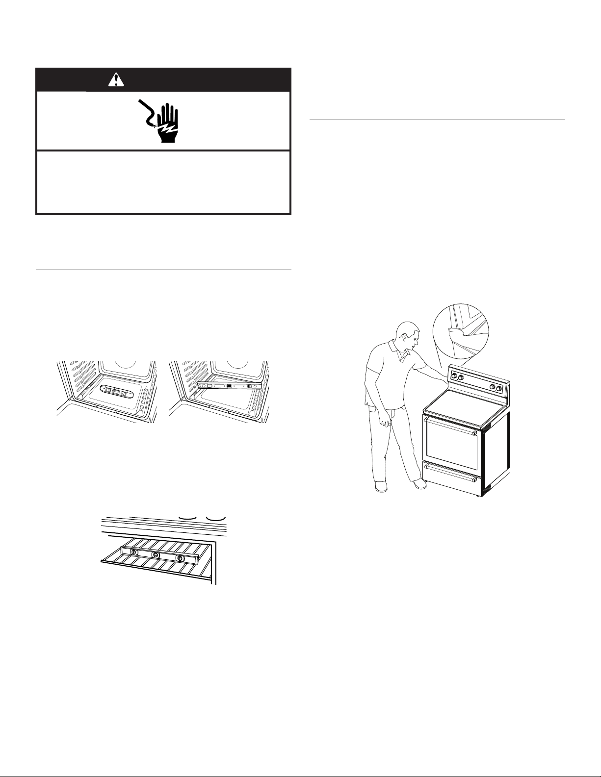
Verify Anti-Tip Bracket Is Installed and
Engaged
On Ranges Equipped with a Storage Drawer:
1. Remove the storage drawer. See “Storage Drawer” section.
2. Use a flashlight to look underneath the bottom of the range.
3. Visually check that the rear range foot is inserted into the slot
of the anti-tip bracket.
On Ranges Equipped with a Warming Drawer or Premium
Storage Drawer:
1. Place the outside of your foot against the bottom front of the
warming drawer or premium storage drawer, and grasp the
lower right-hand or left-hand side of the control panel as
shown.
NOTE: If your countertop is mounted with a backsplash, it
may be necessary to grasp the range higher than is shown in
the illustration.
2. Slowly attempt to tilt the range forward.
If you encounter immediate resistance, the range foot is
engaged in the anti-tip bracket.
3. If the rear of the range lifts more than ½" (1.3 cm) off the floor
without resistance, stop tilting the range and lower it gently
back to the floor. The range foot is not engaged in the anti-tip
bracket.
IMPORTANT: If there is a snapping or popping sound when lifting
the range, the range may not be fully engaged in the bracket.
Check to see if there are obstructions keeping the range from
sliding to the wall or keeping the range foot from sliding into the
bracket. Verify that the bracket is held securely in place by the
mounting screws.
4. Slide the range forward, and verify that the anti-tip bracket is
securely attached to the floor or wall.
5. Slide range back so the rear range foot is inserted into the
slot of the anti-tip bracket.
IMPORTANT: If the back of the range is more than 2" (5.1 cm)
from the mounting wall, the rear range foot may not engage the
bracket. Slide the range forward and determine if there is an
obstruction between the range and the mounting wall. If you
need assistance or service, refer to the “Assistance or Service”
section of the Use and Care Guide, or the cover or “Warranty”
section of the User Instructions, for contact information.
WARNING
Electrical Shock Hazard
Electrically ground range.
Failure to do so can result in death, fire, or
electrical shock.
 Loading...