


YKMHC319EBS
KitchenAid YKMHC319EBS, YKMHS120EW, MMV4207JK, MMV5227JZ, WMH54521JV Installation Instructions
...
MICROWAVE HOOD COMBINATION
INSTALLATION INSTRUCTIONS
This product is suitable for use above electric or gas cooking products up to and including 36" (91.4 cm) wide. See the “Installation
Requirements” section for further notes.
These installation instructions cover different models. The appearance of your particular model may differ slightly from the illustration
in these installation instructions.
INSTRUCTIONS D’INSTALLATION
DE L’ENSEMBLE FOUR À MICRO-ONDES/HOTTE
Ce produit est conçu pour l’utilisation au-dessus d’appareils de cuisson électriques ou à gaz de 36" (91,4 cm) de largeur ou moins.
Voir la section “Exigences d’installation” pour d’autres remarques.
Ces instructions d’installation sont valables pour plusieurs modèles. Il se peut que l’apparence de votre propre modèle soit légèrement
différente de celle montrée sur les illustrations dans ce document.
Table of Contents/Table des matières
MICROWAVE HOOD COMBINATION SAFETY ............................ 2
INSTALLATION REQUIREMENTS ................................................. 2
Tools and Parts ..................................................................................2
Remove Cardboard Template ............................................................ 3
Location Requirements ...................................................................... 3
Product Dimensions...........................................................................3
Electrical Requirements ..................................................................... 4
INSTALLATION INSTRUCTIONS ................................................... 5
Remove Mounting Plate ....................................................................5
Rotate Blower Motor ..........................................................................5
Locate Wall Stud(s) ............................................................................ 8
Mark Rear Wall ................................................................................... 9
Drill Holes in Rear Wall ..................................................................... 10
Attach Mounting Plate to Wall .........................................................10
Prepare Upper Cabinet .................................................................... 11
Install Damper Assembly ................................................................. 11
Install the Microwave Oven ..............................................................12
Complete Installation ....................................................................... 13
VENTING DESIGN SPECIFICATIONS .........................................14
ASSISTANCE ................................................................................15
Replacement Parts ..........................................................................15
Accessories. ..................................................................................... 15
SÉCURITÉ DE L’ENSEMBLE FOUR À
MICRO-ONDES/HOTTE...............................................................16
EXIGENCES D’INSTALLATION ...................................................16
Outillage et pièces ...........................................................................16
Dépose du gabarit de carton ........................................................... 17
Exigences d’emplacement ..............................................................17
Dimensions du produit ..................................................................... 18
Spécications électrique ..................................................................18
INSTRUCTIONS D’INSTALLATION .............................................19
Dépose de la plaque de montage ...................................................19
Réorientation du moteur du ventilateur ........................................... 19
Identier la position du/des poteau(x) du colombage mura ...........22
Tracé sur le mur arrière ....................................................................23
Perçage de trous dans le mur arrière ..............................................24
Fixation de la plaque de montage sur le mur .................................. 24
Préparation du placard supérieur .................................................... 25
Installation du module du clapet anti-reu ...................................... 25
Installation du four à micro-ondes ................................................... 26
Achever l’installation ........................................................................ 28
SPÉCIFICATIONS/CONCEPTION DU CIRCUIT
D’ÉVACUATION ............................................................................28
ASSISTANCE ................................................................................30
Pièces de rechange .........................................................................30
Accessoires.. .................................................................................... 30
W11401909A
MICROWAVE HOOD COMBINATION SAFETY
INSTALLATION REQUIREMENTS
Tools and Parts
Tools Needed
Gather the required tools and parts before starting installation.
Read and follow the instructions provided with any tools listed
here.
■ Measuring tape
■ Pencil
■ Masking tape or thumbtacks
■ Scissors
■ No. 2 Phillips screwdriver
■ No. 3 Phillips screwdriver
for 1/4 - 20 x 3" (7.6 cm)
bolts
■ Drill
■ 3/16" (5 mm), 3/8" (1cm),
5/8" (1.6 cm) drill bits
■ 3/4" (1.9 cm) hole saw
■ Diagonal wire cutting pliers
■ Stud nder
■ 7⁄16" (1.1 cm) socket wrench (or box wrench) for 1/4" x 2"
(6.4 mm x 5.1cm) lag screws
1
■ 1
/2" (3.8 cm) diam. hole drill bit for wood or metal cabinet
■ Keyhole saw
■ Caulking gun and weatherproof caulking compound
■ Duct tape
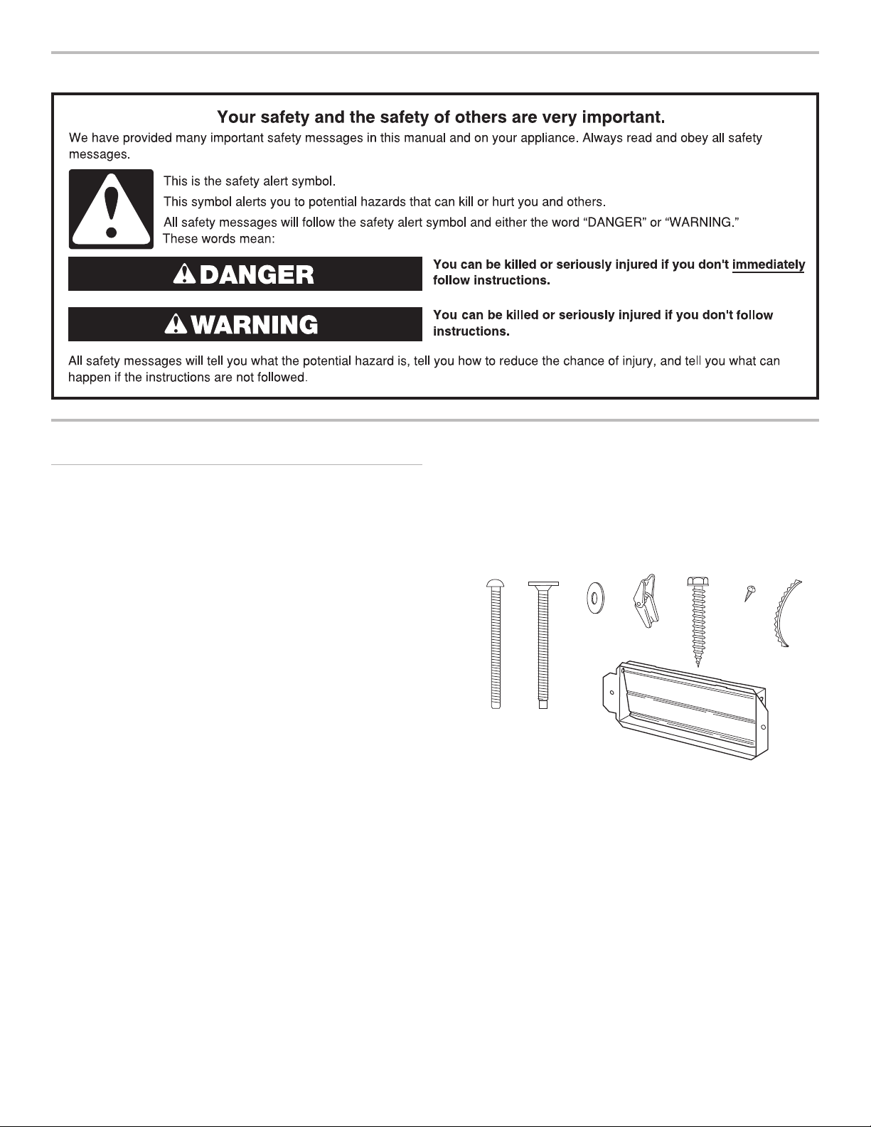
Parts Needed
For information on reordering, see the “Replacement Parts”
section.
NOTE: The hardware items listed here are for wood studs.
For other types of wall structures, be sure to use appropriate
fasteners.
A
A. 3/16 - 24 x 3" round-head
bolts (2)
B. 1/4 - 20 x 3" at-head bolts (2)
C. Washers (2)
D. 3/16" toggle nuts (2)
E. 1/4" x 2" lag screws (2)
F. #6 x 3/8" Sheet metal screws (2)
G. Power supply cord bushing (1)
H. Damper assembly (for wall or
roof venting)
B
C
DEF
H
Not Shown:
■ Upper cabinet template
■ Mounting plate (attached to
back of microwave oven)
■ Cardboard template (part of
packaging) or wall template
■ Aluminum grease lters
■ Charcoal lters (Depending
on model, charcoal lters may
not be included. See User
Instructions.)
G
NOTE: Depending on model, aluminum grease lter and
charcoal lter may be combined.
Materials Needed
Standard ttings for wall or roof venting. See the “Venting Design
Specications” section.
2
Remove Cardboard Template
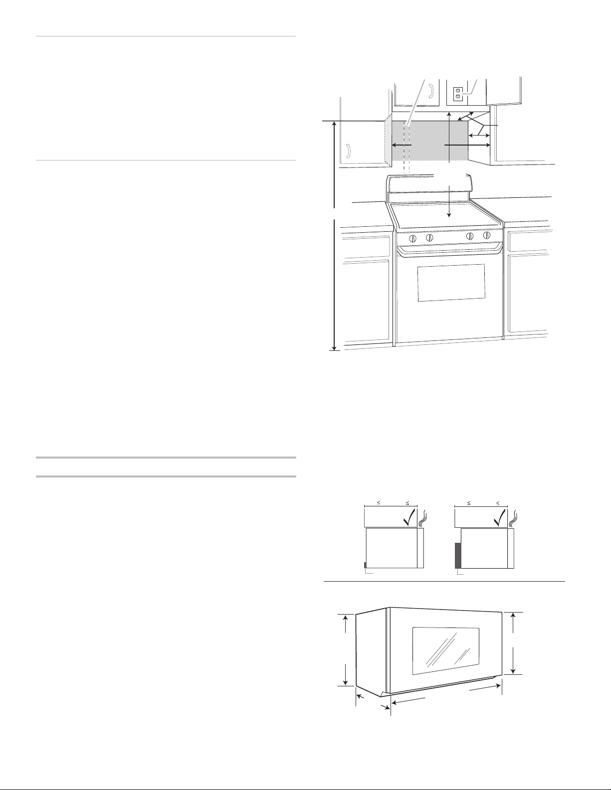
12" (30.5 cm) min.
14" (35.6 cm) max.
30"
(76.2 cm)
min.
AB
upper cabinet and
side cabinet depth
30"
(76.2 cm)
typical*
66" (167.6 cm) min.
Product Dimensions
16
¹⁄₄
"
(41.3 cm)
17
¹⁄₈
"
(43.5 cm)
+/-
³⁄₁₆
"
(0.5 cm)
17"
Up to
(43.2 cm)*
cm)
29
⁷⁄₈
" (76.0
I bar mounting plate
Bump out mounting bracket
12"
DEEPER
14"
14"
DEEPER
15"
The cardboard piece from the top of the microwave oven
packaging is perforated. The piece inside the perforation is for
use as a rear wall template.
1. Cut along the perforation to separate the template from the
rest of the cardboard packaging.
2. Set the cardboard template to the side and refer to it during
the “Mark Rear Wall” part of installation.
Depending on your model, skip "Remove Cardboard Template"
steps if full carton box is used for packing. But use the wall
template for "Mark Rear Wall" part of the installation.
Location Requirements
Check the opening where the microwave oven will be installed.
The location must provide:
■ Minimum installation dimensions. See the “Installation
Dimensions” illustration.
■ Minimum one 2" x 4" (5.1 x 10.2 cm) wood wall stud and
minimum 3/8" (1 cm) thickness drywall or plaster/lath within
cabinet opening.
■ Support for weight of 150 lbs (68 kg) which includes
microwave oven and items placed inside the microwave
oven and upper cabinet.
■ Grounded electrical outlet inside upper cabinet. See the
“Electrical Requirements” section.
NOTES:
■ If installing the microwave oven near a left sidewall, make
sure there is at least 6" (15.2 cm) of clearance between the
wall and the microwave oven so that the door can open fully.
■ Some models have a pocket handle. If installing the
microwave near a right side wall, make sure there is at least
3 inches of clearance between wall and microwave oven so
you can grab the handle integrated inside the door.
■ Some cabinet and building materials are not designed to
withstand the heat produced by the microwave oven for
cooking. Check with your builder or cabinet supplier to make
sure that the materials used will not discolor , delaminate, or
sustain other damages.
Special Requirements
For Wall Venting Installation Only:
■ Cutout must be free of any obstructions so that the vent t
properly and the damper blade opens freely and fully.
For Roof Venting Installation Only:
■ If you are using a rectangular-to-round transition piece, the
3" (7.6 cm) clearance needs to exist above the microwave
oven so that the damper blade can open freely and fully.
See “Rectangular to Round Transition” illustration in the
“Venting Design Specications” section.
Installation Dimensions
NOTE: The grounded 3 prong outlet must be inside the upper
cabinet. See the “Electrical Requirements” section.
A. 2" x 4" (5.1 x 10.2 cm) wall stud
B. Grounded 3 prong outlet
*30" (76.2 cm) is typical for 66" (167.6 cm) installation height.
Exact dimensions may vary depending on type of range/cooktop
below.
NOTE: To ensure good performance, do not obstruct top vent
airow. If cabinets are deeper than 14" (35.6 cm) but no more
than 15" (38.1 cm), use the bump out mounting kit replacing the
I bar mounting plate fr om the wall. The bump out mounting kit
(part # W11185746) is not provided but can be purchased from
Whirlpool.
*Overall depth of product will vary slightly depending on door
design.
3
Electrical Requirements
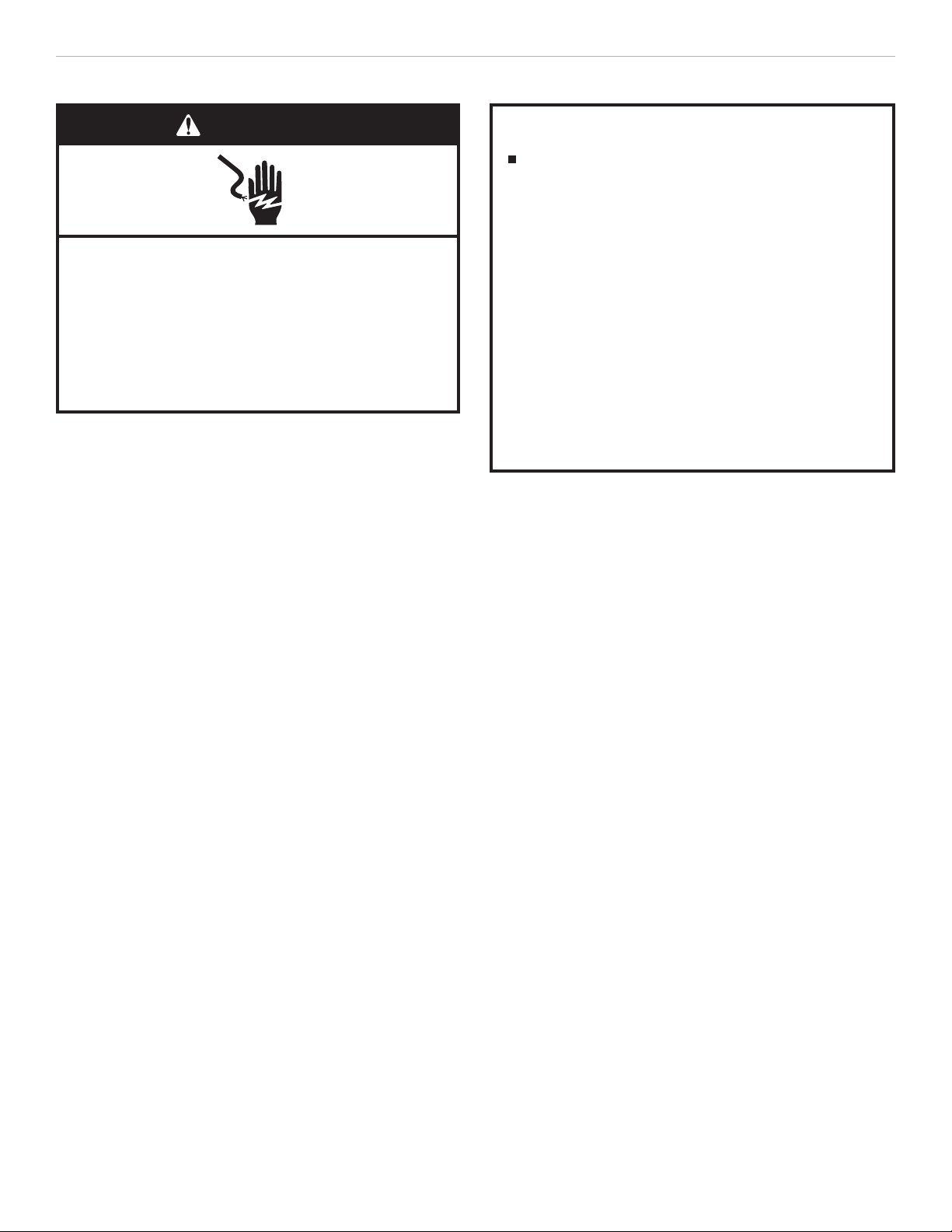
WARNING
Electrical Shock Hazard
Plug into a grounded 3 prong outlet.
Do not remove ground prong.
Do not use an adapter.
Do not use an extension cord.
Failure to follow these instructions can result in death,
fire, or electrical shock.
Observe all governing codes and ordinances.
Required:
■ A 120 V, 60 Hz, AC only, 15 or 20 A electrical supply with a
fuse or circuit breaker
Recommended:
■ A time-delay fuse or time-delay circuit breaker
■ A separate circuit serving only this microwave oven
GROUNDING INSTRUCTIONS
For all cord connected appliances:
The microwave oven must be grounded. In the event of
an electrical short circuit, grounding reduces the risk of
electric shock by providing an escape wire for the electric
current. The microwave oven is equipped with a cord
having a grounding wire with a grounding plug. The plug
must be plugged into an outlet that is properly installed
and grounded.
WARNING: Improper use of the grounding plug can
result in a risk of electric shock. Consult a qualified
electrician or serviceman if the grounding instructions are
not completely understood, or if doubt exists as to whether
the microwave oven is properly grounded.
Do not use an extension cord. If the power supply cord is
too short, have a qualified electrician or serviceman install
an outlet near the microwave oven.
SAVE THESE INSTRUCTIONS
4
INSTALLATION INSTRUCTIONS
A
B
A
A
A
Remove Mounting Plate
Depending on your model, the mounting plate may be in the
foam packaging, or it may be attached to the back of the
microwave oven.
NOTE: To avoid possible damage, cover the work surface.
1. Remove any remaining contents from the microwave oven
cavity.
2. If the mounting plate is attached to the back of the
microwave oven, remove it and set it aside.
3. Tape the microwave oven door closed so that the door does
not swing open while the microwave oven is being handled.
NOTE: To avoid damage to the microwave oven, do not grip or
use the door or door handle while the microwave oven is being
handled.
Rotate Blower Motor
The microwave oven is set for recirculation installation. For wall
or roof venting, changes must be made to the venting system.
NOTE: Skip this section if you are using recirculation installation.
Keep the damper assembly in case the venting method is
changed, or the microwave oven is reinstalled in another location
where wall or roof venting may be used.
Wall Venting Installation Only
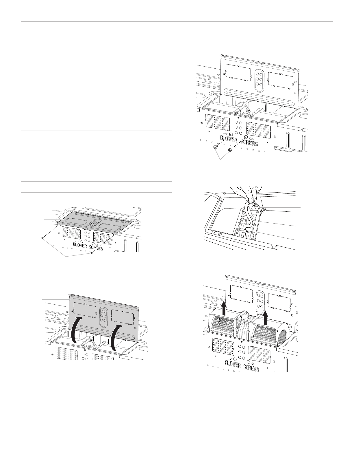
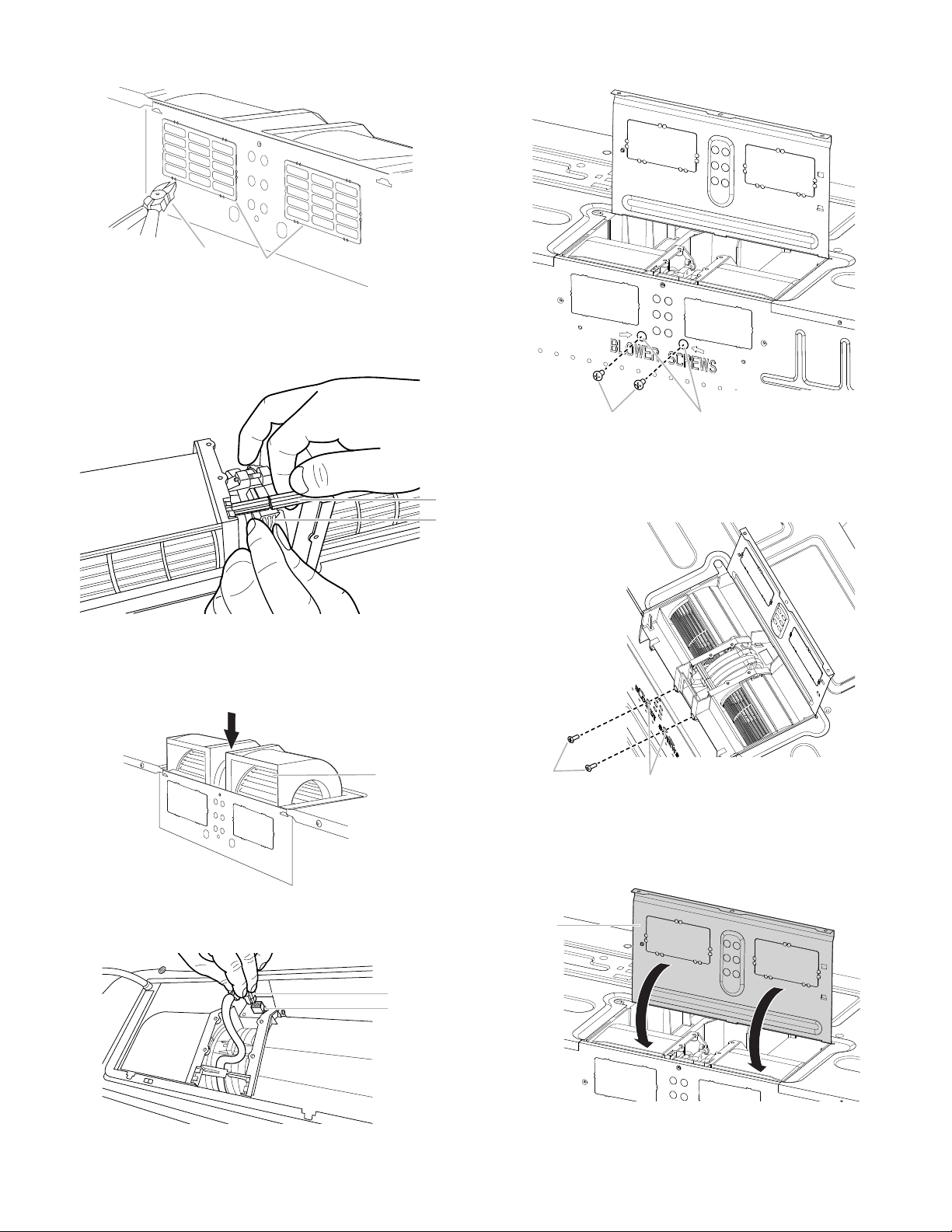
1. Remove screws attaching damper plate to back of
microwave oven, set the screws aside.
3. Remove 2 blower screws attaching blower motor to the
microwave oven, and set aside.
A. Blower screws (in recessed holes)
4. Disconnect the blower motor wire from the connector.
A
B
A. Blower motor wire
B. Connector
A. Damper plate
B. Screws
2. Turn and hold the damper plate vertically as shown.
A. Damper plate
5. Lift blower motor out of microwave oven, and set aside.
A. Blower Motor
5
6. Using diagonal wire cutting pliers, gently snip out the
B
A
A
B
A B
A
B
A
rectangular damper vent covers at the perforations.
A. Diagonal wire cutting pliers
B. Rectangular damper vent cover
7. Hold the blower motor wire, put the wire through the blower
motor bridge.
10. Reattach the 2 blower screws into the recessed holes in the
back of the microwave.
A. Screws
B. Recessed holes
A
B
A. Blower motor bridge
B. Blower motor wire
8. Lower blower motor back into the microwave oven. Exhaust
ports face the back of the microwave oven.
A
A. Exhaust Port
9. Reconnect the blower motor wire into the connector.
11. Check to make sure the 2 screws are secured properly in the
blower motor screw holes, so that the motor cannot move.
A. Screws
B. Blower motor screw holes
12. Return the damper plate to its original horizontal position.
A. Blower motor wire
B. Connector
6
A. Damper plate
13. Secure damper plate with 2 screws removed in Step 1.
A
B
A. Damper plate
B. Screws
Roof Venting Installation Only
1. Repeat Step 1 from “Wall Venting Installation Only.”
2. Repeat Step 2 from “Wall Venting Installation Only.”
3. Repeat Step 3 from “Wall Venting Installation Only.”
4. Repeat Step 4 from “Wall Venting Installation Only.”
5. Repeat Step 5 from “Wall Venting Installation Only.”
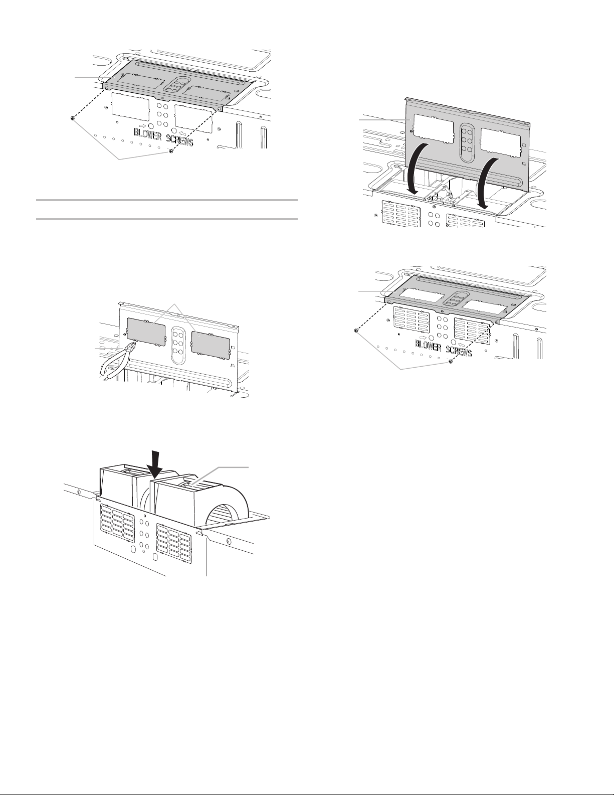
6. Using diagonal wire cutting pliers, gently snip out the
rectangular vent covers on the damper plate at the
perforations.
A
8. Reconnect the blower motor wire into the connector.
9. Reattach the 2 blower screws into the recessed holes in the
back of the microwave.
10. Check to make sure the 2 screws are secured properly in the
blower motor screw holes, so that the motor cannot move.
11. Return the damper plate to its original horizontal position.
A
A. Damper plate
12. Secure damper plate with 2 screws removed in Step 1.
A
B
A. Rectangular vent covers
B. Diagonal wire cutting pliers
7. Lower blower motor back into microwave oven. Exhaust
ports face the top of microwave oven.
A
A. Exhaust port
IMPORTANT: If blower motor is not positioned with at
side facing the back of the microwave oven (as shown),
performance will be poor.
B
A. Damper plate
B. Screws
7
Locate Wall Stud(s)
Figure 1
C
C
D
E
F
Figure 3
D
C
E
Figure 2
B
C
E
F
Figure 4
A,D
D
NOTE: If no wall studs exist within the cabinet opening, do not
install the microwave oven.
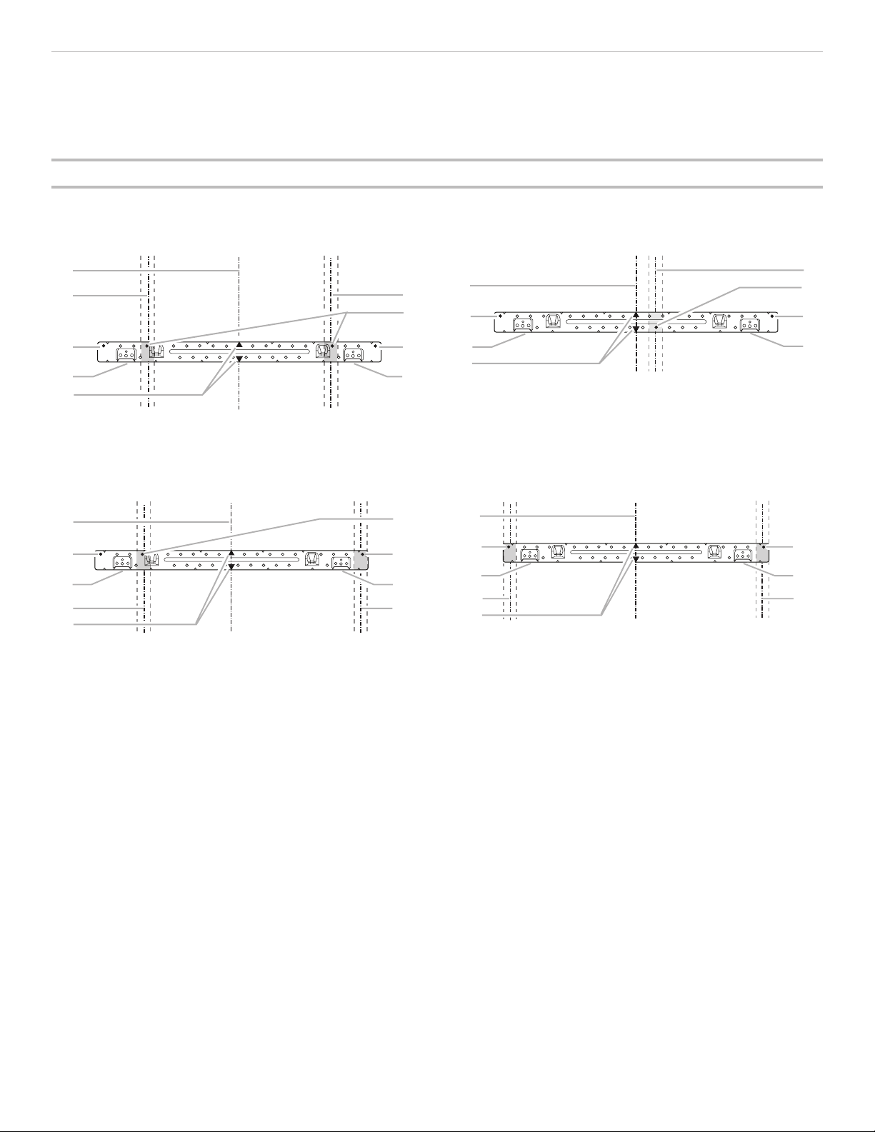
See illustrations in “Possible Wall Stud Congurations.”
Possible Wall Stud Congurations
These depictions show examples of preferred installation congurations with the mounting plate.
1. Using a stud nder, locate the edges of the wall stud(s)
within the opening.
2. Mark the center of each stud, and draw a plumb line down
each stud center. See illustrations in “Possible Wall Stud
Congurations.”
No Wall Studs at End Holes
No Wall Studs at End Holes
B
D
A
A
A
A
E
E
NOTE: If wall stud is within 6" (15.2 cm) of the vertical centerline
(see the “Mark Rear Wall” section), only recirculation or roof
venting installation can be done.
Wall Stud at End Hole
B
A
F
D
A,
E
C
B
E
C
F
Wall Studs at End Holes
A,
E
C
A. End holes (on mounting plate)
B. Cabinet opening vertical centerline
C. Wall stud centerlines
D. Holes for lag screws
E. Support tabs
F. Mounting plate center markers
8
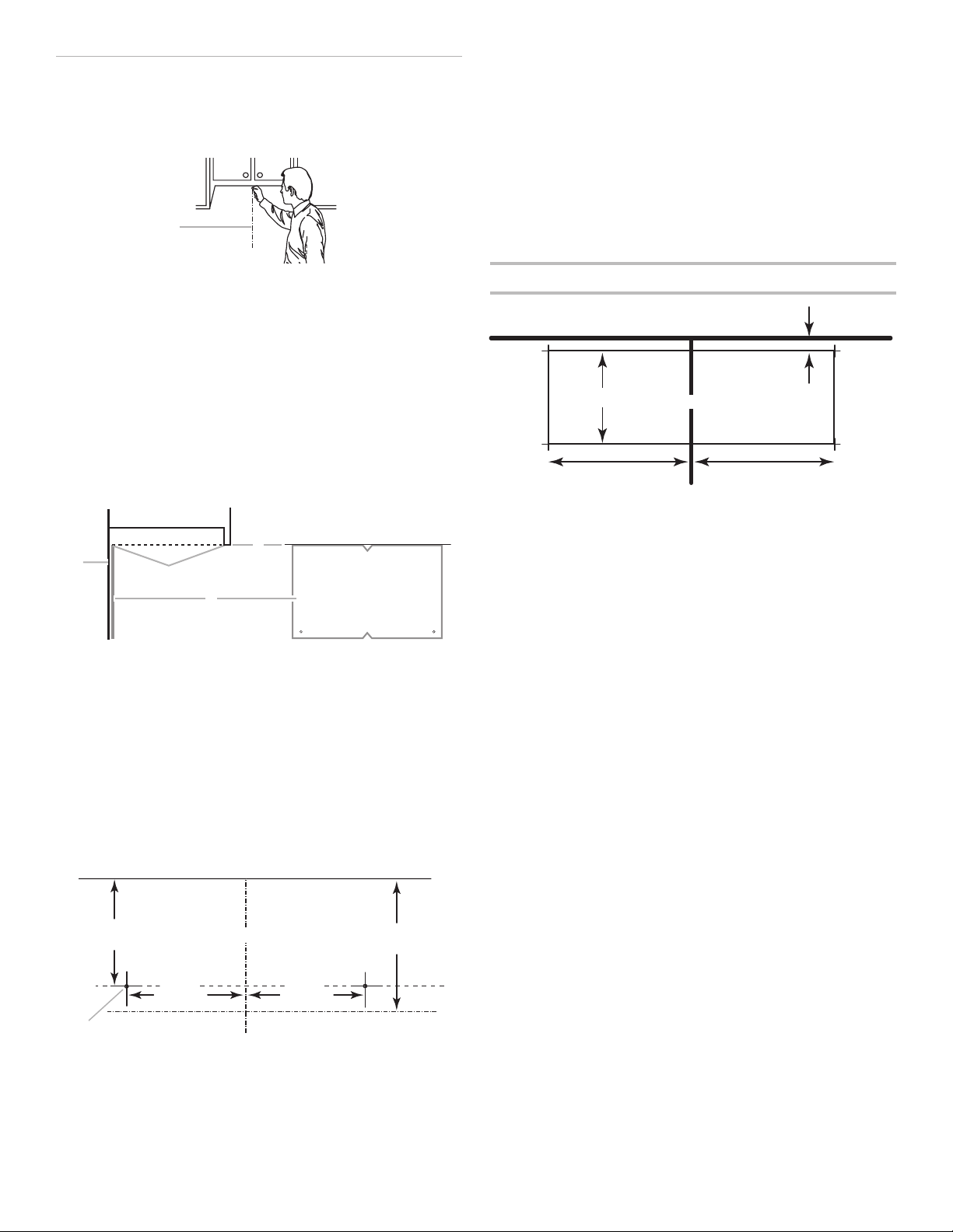
Mark Rear Wall
A
A
Mounting plate end hole
Upper cabinet bottom
The microwave oven must be installed on a minimum of 1 wall
stud, preferably 2, using a minimum of 1 lag screw, preferably 2.
1. Using measuring tape, nd and clearly mark the vertical
centerline of the opening.
5. With the support tabs facing forward (see illustrations in
the “Locate Wall Stud(s)” section), align the mounting plate
center markers to the centerline on the wall, making sure its
bottom edge is aligned to the horizontal line drawn in Step 3
and that the end holes are properly marked. Make sure the
mounting plate is level.
6. Holding the mounting plate in place, find the wall stud
centerline(s) drawn in Step 2 of “Locate Wall Stud(s)” and
mark at least 1, preferably 2 hole(s) through the mounting
plate, closest to the wall stud centerline(s). See figures 1,
2, and/or 3 in “Possible Wall Stud Congurations” in the
“Locate Wall Stud(s)” section. The blackened holes in the
shaded areas are ideal hole locations.
7. Set the mounting plate aside.
A. Centerline
2. Align the center markers on the cardboard template (carton
top cap) or Wall template, to the centerline on the wall,
making sure it is level, and that the top of the cardboard
template or wall template is butted up against the bottom
edge of the upper cabinet.
NOTES:
■ If the front edge of the upper cabinet is lower than the back
edge, lower the cardboard template or wall template so that
its top is level with the front edge of the cabinet.
■ If the cardboard template or wall template is damaged or
unusable, measure and mark the wall with the dimensions
described in Step 4.
D
C
B
A. Rear wall
B. Cardboard template or Wall template
C. Top of cardboard template or wall template
must align with front edge of cabinet.
D. Front edge of upper cabinet
Wall Venting Installation Only
Upper cabinet bottom
4" (10.2 cm)
6" (15.2 cm)6" (15.2 cm)
Centerline
8. Mark the centerline 3/8" (1 cm) down from the bottom edge
of the upper cabinet.
9. Using measuring tape, measure out 6" (15.2 cm) on both
sides of the centerline, and mark.
10. Measure down 4" (10.2 cm) from the mark made in Step 8
and mark.
11. Using a straightedge, draw the 2 horizontal, level lines
through the marks made in steps 8 and 10.
12. Draw the 2 vertical plumb lines down from the marks made
in Step 9 to complete the 12" x 4" (30.5 x 10.2 cm) rectangle.
This is the venting cutout area.
13. Cut a 3/4" (1.9 cm) hole in one corner of the cutout area.
14. Using a keyhole saw, cut out the venting cutout area.
³⁄₈
" (1 cm)
3. Holding the cardboard template or wall template in place,
mark both holes in the lower corners and draw a horizontal
line across the bottom edge of the cardboard template or
wall template. These represent the mounting plate’s end
holes and bottom edge.
4. Remove the cardboard template or wall template and check
the markings:
15⁵⁄₈"
(39.71 cm)
■ The bottom edge line must be 17
bottom of the upper cabinet and must be level.
■ The end holes must be 15
edge of the upper cabinet and must be on a level line with
each other. They must each be 141⁄8" (35.96 cm) from the
centerline.
14¹⁄₈"
(35.96 cm)
Centerline
14¹⁄₈"
(35.96 cm)
Bottom of mounting plate
5
⁄16" (44.02 cm) from the
5
⁄8" (39.71 cm) from the bottom
17⁵⁄₁₆"
(44.02 cm)
9
Drill Holes in Rear Wall
C
A
A
B
In addition to being installed on at least 1 wall stud, the
mounting plate must attach to the wall at both end holes. If the
end holes are not over wall studs, use two 3/16-24 x 3"
round-head bolts with toggle nuts; if 1 end hole is over a wall
stud, use 1 lag screw and one 3/16-24 x 3" round-head bolt with
toggle nut; or if both end holes are over wall studs, use 2 lag
screws. Following are 3 installation congurations.
Installation for No Wall Studs at End Holes
(Figures 1 and 2)
1. Drill 5/8" (1.6 cm) holes through the wall at both end holes
marked in Step 3 of the “Mark Rear Wall.”
2. Drill 3/16" (5 mm) hole(s) into the wall stud(s) at the hole(s)
marked in Step 6 of the “Mark Rear Wall.” Refer to gures 1
and 2 in “Possible Wall Stud Congurations” in the “Locate
Wall Stud(s)” section.
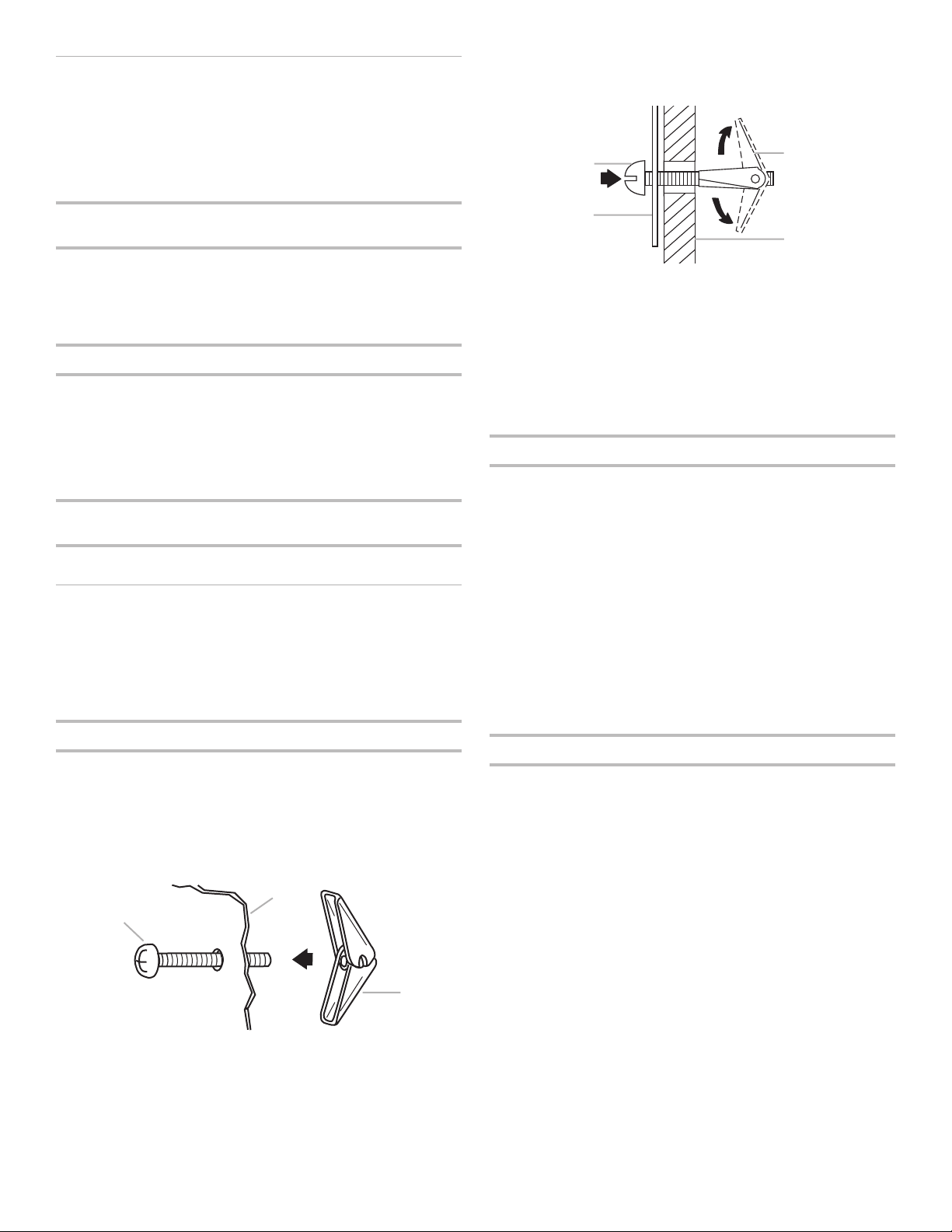
4. Push the 2 bolts with toggle nuts through the drywall, and
nger tighten the bolts to make sure toggle nuts have
opened against drywall.
C
D
A. 3/16-24 x 3" round-head bolt
B. Mounting plate
C. Spring toggle nut
D. Drywall
Installation for Wall Stud at One End Hole (Figure 3)
1. Drill a 3/16" (5 mm) hole into the wall stud at the end hole
marked in Step 3 of the “Mark Rear Wall.”
2. If installing on a second wall stud, drill a 3/16" (5 mm) hole
into the wall stud at the other hole marked in Step 6 of the
“Mark Rear Wall.” Refer to Figure 3 in “Possible Wall Stud
Congurations” in the “Locate all Stud(s)” section.
3. Drill a 5/8" (1.6 cm) hole through the wall at the other end
hole.
Installation for Wall Studs at Both End Holes
(Figure 4)
1. Drill 3/16" (5 mm) holes into the studs at the end holes
marked in Step 3 of the “Mark Rear Wall.”
Attach Mounting Plate to Wall
NOTE: Secure the mounting plate to the wall at both end holes
drilled into the wall studs and/or drywall using either 3/16-24 x
3" (7.6 cm) round-head bolts and toggle nuts or 1/4 x 2" (5.1 cm)
lag screws.
Refer to illustrations in “Possible Wall Stud Congurations” in the
“Locate Wall Stud(s)” section.
No Wall Studs at End Holes (Figures 1 and 2)
NOTE: The mounting plate must be secured to the wall on at
least 1 wall stud as well as at both ends.
1. With the support tabs of the mounting plate facing forward,
insert 3/16-24 x 3" round-head bolts through both end holes
of mounting plate.
2. Start toggle nuts on bolts from the back of the mounting
plate. Leave enough space for the toggle nuts to go through
the wall and to open.
5. Insert lag screw(s) into the hole(s) drilled into wall stud(s) in
Step 2 of “Installation for No Wall Studs at End Holes” in the
“Drill Holes in Rear Wall” section.
6. Check alignment of mounting plate, making sure it is level.
7. Securely tighten all lag screws and bolts.
Wall Stud at One End Hole (Figure 3)
1. With the support tabs of the mounting plate facing forward,
insert a 3/16-24 x 3" round-head bolt through the end
hole that ts over the 5/8" (16 mm) hole drilled in Step 3 of
“Installation for Wall Stud at One End Hole” in the “Drill Holes
in Rear Wall” section.
2. Start a toggle nut on the bolt from the back of the mounting
plate. Leave enough space for the toggle nut to go through
the wall and to open.
3. Position mounting plate on the wall.
4. Push the bolt with toggle nut through the drywall, and nger
tighten the bolt to make sure toggle nut has opened against
drywall.
5. Insert a lag screw into the remaining end hole.
6. If installing on a second wall stud, insert a lag screw into the
other hole drilled in Step 2 of “Installation for Wall Stud at
One End Hole” in the “Drill Holes in Rear Wall” section.
7. Check alignment of mounting plate, making sure it is level.
8. Securely tighten the lag screw(s) and bolt.
Wall Studs at Both End Holes (Figure 4)
1. Position mounting plate on the wall.
2. Insert lag screws into both end holes.
3. Check alignment of mounting plate, making sure it is level.
4. Securely tighten the lag screws.
B
A. 3/16-24 x 3" round-head bolt
B. Mounting plate
C. Spring toggle nut
3. Position mounting plate on the wall.
10
 Loading...