

KitchenAid KESS300B, KESC300B, KGST300B, KGST307B, KERS500B Reference Manual
...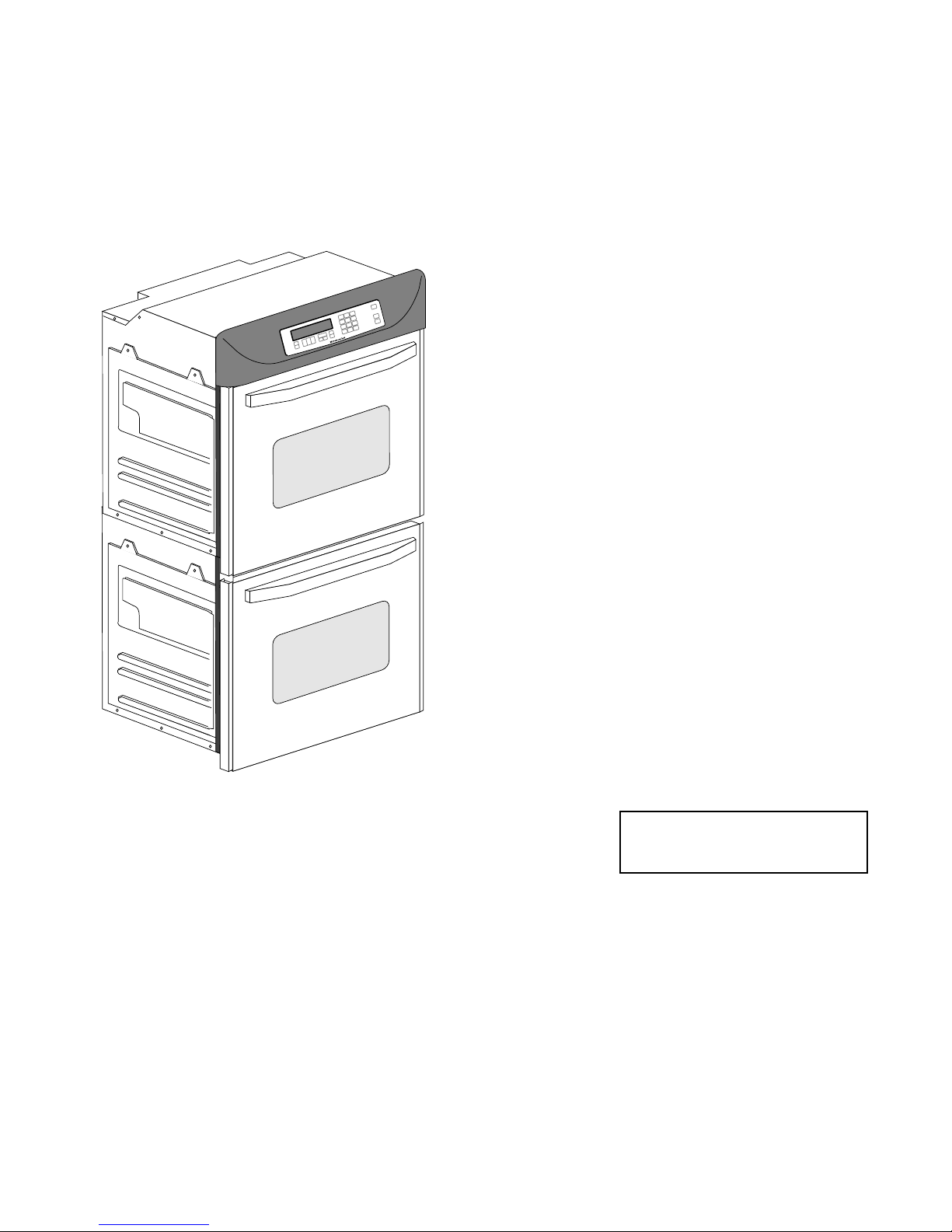
KITCHENAID
ELECTRONIC
RANGE
CONTROLS
“B” & “D” LINE WALL OVENS
JOB AID
Part No. 4317169

FORWARD
This Job Aid is a reference guide for the experienced technician. It is not
designed as a replacement to basic training, and does not replace the Service Manual or the Use and Care Guide.
OBJECTIVE
The objective of this Job Aid is to allow the experienced appliance technician to become familiar with the operation of the KitchenAid Electronic Range
Control. This Job Aid follows the instructions contained on the companion
training disk, and is designed as reference material.
WHIRLPOOL CORPORATION assumes no responsibility for any repair
made on our products by anyone other than Authorized Factory Service Technicians.
Copyright 1995 Whirlpool Corporation
- ii -

Table of Contents
KitchenAid Electronic Range Controls—“B” Line Slide-In..................................................... Page 2
KitchenAid Electronic Range Controls—“B” Line Freestanding ........................................... Page 4
KitchenAid Electronic Range Controls—“B” Line Freestanding/Slide-In ............................ Page 6
KitchenAid Electronic Range Controls—“D” Line Wall Ovens .............................................. Page 7
Reading The Graphic Display.................................................................................................. Page 12
KitchenAid Electronic Range Controls—“Easy Convect” ....................................................Page 13
KitchenAid Electronic Range Controls—“Easy Convect (Meats)”...................................... Page 14
KitchenAid Electronic Range Controls—“Sabbath Mode” ................................................... Page 23
KitchenAid Electronic Range Controls—“Clean Mode” .......................................................Page 32
- iii -

— NOTES —
- iv -
Important Safety Information
WARNING
This manual is intended for factory-service technicians only. We recommend that customers DO NOT
service their own units, because of the complexity and risk of high-voltage electrical shock.
The following information is used throughout this manual, and should be read carefully.
NOTE
Helpful information that explains a more complicated step, prior to carrying it out .
CAUTION
Information that will help you avoid actions that
could cause product damage (scratches, dents,
etc.) and damage to personal property.
WARNING
Information that alerts you to potentially dangerous conditions. These conditions can cause
serious personal injury (burns, fire and electrical
shock, etc.) if the suggested procedures are not
observed.
Fire Hazard
Do not obstruct the flow of ventilation air.
Electrical Shock Hazard
It is the customer’s responsibility to:
• Contact a qualified electrical installer.
• Assure that electrical installation is adequate
and in conformance with the National Electrical Code, ANSI/NFPA 70—latest edition*,
and all local codes and ordinances.
Failure to do so could result in fire, electrical
shock, or other personal injury.
Take special care when drilling holes into the
wall for venting or electrical wiring. Electrical
wires may be concealed behind the wall covering.
Failure to do so could result in fire, electrical
shock, or other personal injury.
* National Fire Protection Association
Batterymarch Park
Quincy, Massachusetts 02269
BILITY FOR ANY REPAIRS MADE ON OUR PROD-
UCTS BY ANYONE OTHER THAN AUTHORIZED
ASSUMES NO RESPONSI-
SM
SERVICE TECHNICIANS.
- 1 -
Installation Layout
SLIDE-IN ELECTRIC RANGES
Refer to Figure 1 while you read the following
installation information.
Proper installation is your responsibility. A qualified technician must install this range. Make sure
you have everything necessary for correct installation. It is the responsibility of the installer to comply
with the installation clearances specified on the
serial/rating plate. This plate is located behind the
oven door at the top of the left front frame. IMPOR-
TANT: Be sure to observe all governing codes and
ordinances.
Clearance Note:
A clearance of 30" (76.2 cm)
minimum is required when the bottom of a wood or
metal cabinet is protected by not less than
1
/4" of
flame-retardant millboard covered with not less
"
(33 cm)
13
max. upper
cabinet depth
"
(76.2 cm) min.
30
cabinet opening width
1
/2" (1.3 cm)
radius for both
"
(45.7 cm)
18
upper cabinet to
countertop
4" (10.2 cm) min.
clearance to side
wall or other combustible material on
both sides of the
range.
corners
3
/8" (77.2 cm) min.
30-
opening width
Wall receptacle is
8" (2-.3 cm) to 22"
(55.9 cm) from
either cabinet.
7" (17.8 cm) max.
from floor.
than #28 MSG sheet steel, 0.015" stainless steel,
0.024
"
aluminum, or 0.020" copper. A minimum
clearance of 36
"
(91.4 cm) between the top of the
cooking platform and the bottom of an unprotected
wood or metal cabinet is required.
The cutout shown is for a 25
with a 24
"
(61 cm) base cabinet and no backsplash.
"
(63.5 cm) countertop
The maximum depth for overhead cabinets is 13
(33 cm). For the minimum vertical clearance between the cooking surface and the overhead cabinets, see the previous “Clearance Note.” Overhead cabinets installed at either side of the range
must be a minimum of 18
"
(45.7 cm) above the
cooking surface. The minimum horizontal distance
between the overhead cabinets is 30
The Anti-Tip bracket MUST be
installed.
Refer to
“Clearance
Note” above.
3
/4" (57.8 cm)
22-
opening depth
The range should be located away
from strong draft areas, such as
windows, doors, and strong heating vents or fans. The range should
be located for convenient use in
the kitchen. Recessed installations
must provide complete enclosure
of the sides and rear of the range.
All openings in the wall or floor
where the range is to be installed
must be sealed.
Do not pinch the power cord between the range and the wall when
you push the range into its mounting location.
The shaded area shown in the illustration is the recommended area
for a 120-VAC outlet on the rear
wall and area for a through-thewall connection for gas pipe and
shutoff valve.
"
(76.2 cm).
"
7
/8" (2.2 cm)
min. required
between cutout
and cabinet door
or hinge.
"
(91.4 cm)
36
countertop
height
A grounded electrical outlet is required for this range.
FIGURE 1
Dimensions For Installing The Slide-In
Electric Range
- 2 -
FREESTANDING GAS RANGES
Refer to Figure 2 while you read the following
installation information.
Proper installation is your responsibility. A qualified technician must install this range. Make sure
you have everything necessary for correct installation. It is the responsibility of the installer to comply
with the installation clearances specified on the
serial/rating plate. This plate is located behind the
oven door at the top of the left front frame. IMPOR-
TANT: Be sure to observe all governing codes and
ordinances.
Clearance Note:
A clearance of 30" (76.2 cm)
minimum is required when the bottom of a wood or
metal cabinet is protected by not less than
1
/4" of
flame-retardant millboard covered with not less
13" (33 cm)
max.upper
cabinet depth
"
(76.2 cm) min.
30
cabinet opening width
3
/8" (77.2 cm) min.
4" (10.2 cm) min.
clearance to side
wall or other combustible material on
both sides of the
range.
Gas line opening can
be located within this
shaded area.
This area is recommended for throughthe-cabinet gas
connection and
shutoff valve
located directly
below the
pressure regulator.
9"
(22.9 cm)
(5.1 cm)
30-
opening width
18"
(45.7 cm)
1
/2
"
2-
6.4 cm
(6.4 cm)
24"
(64 cm)
2"
7
/8" (2.2 cm) min. required between cabinet
opening and door or
hinge opening.
than #28 MSG sheet steel, 0.015
0.024
"
aluminum, or 0.020" copper. A minimum
clearance of 36
"
(91.4 cm) between the top of the
"
stainless steel,
cooking platform and the bottom of an unprotected
wood or metal cabinet is required.
The cutout shown is for a 25
with a 24
"
(61 cm) base cabinet and no backsplash.
"
(63.5 cm) countertop
The maximum depth for overhead cabinets is 13
(33 cm). For the minimum vertical clearance between the cooking surface and the overhead cabinets, see the previous “Clearance Note.” Overhead cabinets installed at either side of the range
must be a minimum of 18
"
(45.7 cm) above the
cooking surface. The minimum horizontal distance
between the overhead cabinets is 30
"
(45.7 cm) min.
18
Refer to
“Clearance
Note” above.
6"
(15.2 CM)
10"
(25.4 cm)
This area is
recommended
for 120 VAC outlet
on rear wall
1
/2
"
2-
clearance upper cabinet
to countertop
"
(91.4 cm)
36
countertop
height
The Anti-Tip bracket MUST be
installed.
The range should be located away
from strong draft areas, such as
windows, doors, and strong heating vents or fans. The range should
be located for convenient use in
the kitchen. Recessed installations
must provide complete enclosure
of the sides and rear of the range.
All openings in the wall or floor
where the range is to be installed
must be sealed.
Do not pinch the power cord between the range and the wall when
you push the range into its mounting location.
The shaded area shown in the illustration is the recommended area
for a 120-VAC outlet on the rear
wall and area for a through-thewall connection for gas pipe and
shutoff valve.
A grounded electrical outlet is
required for this range.
FIGURE 2
Dimensions For Installing The
Freestanding Gas Range
"
(76.2 cm).
"
- 3 -

Electronic Range Controls
• Used on Gas & Electric Models.
– Slide-In: Up front glass “Capacitive Touch” switch membrane.
– Freestanding: Up front glass “Capacitive Touch” membrane.
• Unique Functions:
– Sabbath Mode: Allows the oven to be operated continuously
during the Jewish Sabbath.
– Easy Convect: Automatically converts standard cooking times
and temperatures to convection cooking times and
temperatures.
– Full Meal Convect: Ten preprogrammed cook cycles and one fa-
vorite cooking cycle.
• 2nd through 5th year parts only warranty on the control.
• Electric Models:
– KESS300B
– KESC300B
– KESC307B
– KESH307B
Freestanding
• Electric Models
(Available in late 1995):
– KERS500B
– KERC500B
– KERC507B
– KERH507B
Slide-In
• Gas Models:
– KGST300B
– KGST307B
• Gas Models:
– KGRT500B
– KGRT507B
- 4 -
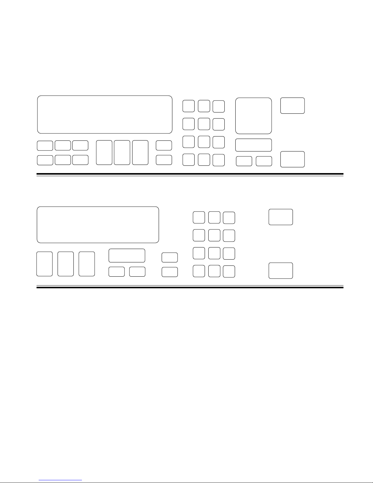
Electronic Range Controls
Keypad Layout
Convection Slide-In
Slide-In
Graphic Oven Display
23
1
4
56
78 9
Keypad Layout
Non-Convection Slide-In
Graphic Oven Display
CLOCK
12 3
SET - START
SET
START
CANCEL
10
11
10
11
#1 #2 #3
#4 #5 #6
#7 #8 #9
OVEN
#0
#12
#1 #2 #3
#4 #5 #6
#7 #8 #9
Control
LOCK
LIGHT
#0
OVEN
LIGHT
88: 88
HR MIN MIN SEC
CLOCK
SET - START
SET
START
CANCEL
START
CANCEL
OFF
START
CANCEL
OFF
Keypads:
1 = Bake
2 = Broil
3 = Clean
4 = Convection Bake
5 = Convection Broil
6 = Convection Roast
7 = Easy Convection (Baked Goods)
8 = Easy Convection (Meats)
9 = Easy Convection (Other Foods)
10 = Cook Time
11 = Stop Time
12 = Convection Full Meal
- 5 -
Electronic Range Controls
Keypad Layout
Convection Freestanding
Freestanding
Graphic Oven Display
23
1
78 9
56
4
Keypad Layout
Non-Convection Freestanding
Graphic Oven Display
CLOCK
SET - START
12 3
SET
START
CANCEL
10
11
10
11
#1 #2 #3
#4 #5 #6
#7 #8 #9
#0
#12
ON
NIGHT
OFF
SURFACE LIGHT
#1 #2 #3
#4 #5 #6
#7 #8 #9
SURFACE
#0
LIGHT
OVEN
LIGHT
OVEN
LIGHT
88: 88
HR MIN MIN SEC
CLOCK
SET - START
SET
START
CANCEL
START
CANCEL
OFF
START
CANCEL
OFF
Keypads:
1 = Bake
2 = Broil
3 = Clean
4 = Convection Bake
5 = Convection Broil
6 = Convection Roast
7 = Easy Convection (Baked Goods)
8 = Easy Convection (Meats)
9 = Easy Convection (Other Foods)
10 = Cook Time
11 = Stop Time
12 = Convection Full Meal
- 6 -
Electronic Range Controls
The Graphic Display
NOTE: Ring element used on electric models only.
EASYCONVECT
NONCONVECTION MODELS
NIGHT LIGHT DELAY
SET PROBE TEMP
888
ON
RAISING
F
BREAD
DEHYDRATE CONVECTION
ENTER STANDARD COOK TIME
COOK TEMP CLEAN TIME
8:88
CHECK
FOOD AT
CLOSE CONTROL LOCK
DOOR LOCKED START ?
CONVECTION MODELS
8:88
ON
TEMP PROBE TIMED DELAY
CONTROL
DOOR LOCKED
F
START ?
88:88
HR MIN MIN SEC
CLEAN
STOP
COOK TIMER
18:88
18:88
START
TIME
STOP
TIME
- 7 -
Electronic Range Controls
Reading The Graphic Display
Broiler Heat Indicator
NIGHT LIGHT DELAY
888
ON
EASYCONVECT
Bake Heat Indicator
Ring Element
Electric Convection Only
Meat Probe Indicator
Time Savings Bar Indicates:
% Of Time Remaining In Cook Cycle
OR
SET PROBE TEMP
RAISING
F
BREAD
DEHYDRATE CONVECTION
ENTER STANDARD COOK TIME
COOK TEMP CLEAN TIME
8:88
START
18:88
CHECK
FOOD AT
CLOSE CONTROL LOCK
DOOR LOCKED START ?
18:88
TIME
STOP
TIME
% Of Time Saved With EasyConvect
- 8 -
Electronic Range Controls
Easy Convect™
• Available on convection models only.
• Allows the consumer to cook standard oven recipes in
the convection mode.
• Three Easy Convect cooking functions:
– Baked Goods: Converts temperature by –50˚F.
– Meats: Converts time by –20% and temperature by –25˚F.
– Other: Converts time by –10% and temperature by –25˚F.
Easy Convect (Meats)
NIGHT LIGHT DELAY
SET PROBE TEMP
RAISING
EASYCONVECT
F
BREAD
DEHYDRATE CONVECTION
ENTER STANDARD COOK TIME
ON
COOK TEMP CLEAN TIME
8:88
CONVECTION MODELS
NOTE:
Ring element used
on electric models
only.
Meats
#1 #2 #3
#4 #5 #6
#7 #8 #9
#0
#12
OVEN
LIGHT
START
18:88
START
CANCEL
18:88
OFF
CHECK
FOOD AT
CLOSE CONTROL LOCK
DOOR LOCKED START ?
TIME
STOP
TIME
Time of Day
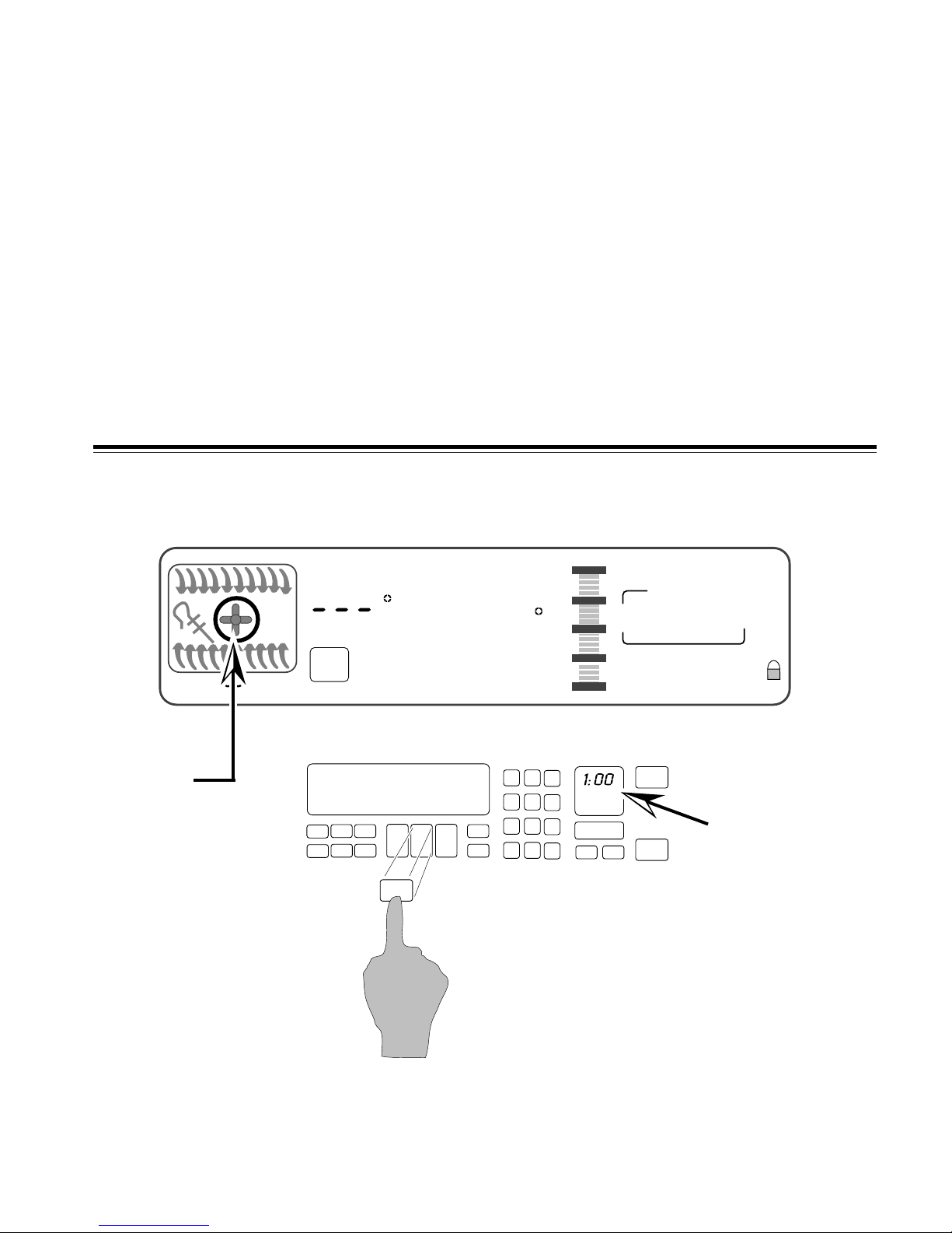
Press the “Meats” keypad.
- 9 -
Electronic Range Controls
Easy Convect (Meats)
START
TIME
STOP
TIME
Time of Day
EASYCONVECT
NOTE:
Ring element used
on electric models
only.
NIGHT LIGHT DELAY
SET PROBE TEMP
325
ON
RAISING
F
BREAD
DEHYDRATE CONVECTION
ENTER STANDARD COOK TIME
COOK TEMP CLEAN TIME
#1 #2 #3
#4 #5 #6
#7 #8 #9
#0
#12
18:88
18:88
CHECK
FOOD AT
CLOSE CONTROL LOCK
DOOR LOCKED START ?
START
OVEN
LIGHT
CANCEL
OFF
CONVECTION MODELS
Enter the normal cooking temperature.
START
TIME
STOP
TIME
Time of Day
EASYCONVECT
NOTE:
Ring element used
on electric models
only.
NIGHT LIGHT DELAY
SET PROBE TEMP
325
ON
RAISING
F
BREAD
DEHYDRATE CONVECTION
ENTER STANDARD COOK TIME
COOK TEMP CLEAN TIME
#1 #2 #3
#4 #5 #6
#7 #8 #9
#0
#12
18:88
18:88
CHECK
FOOD AT
CLOSE CONTROL LOCK
DOOR LOCKED START ?
START
OVEN
LIGHT
CANCEL
OFF
CONVECTION MODELS
Enter the normal cooking time.
- 10 -
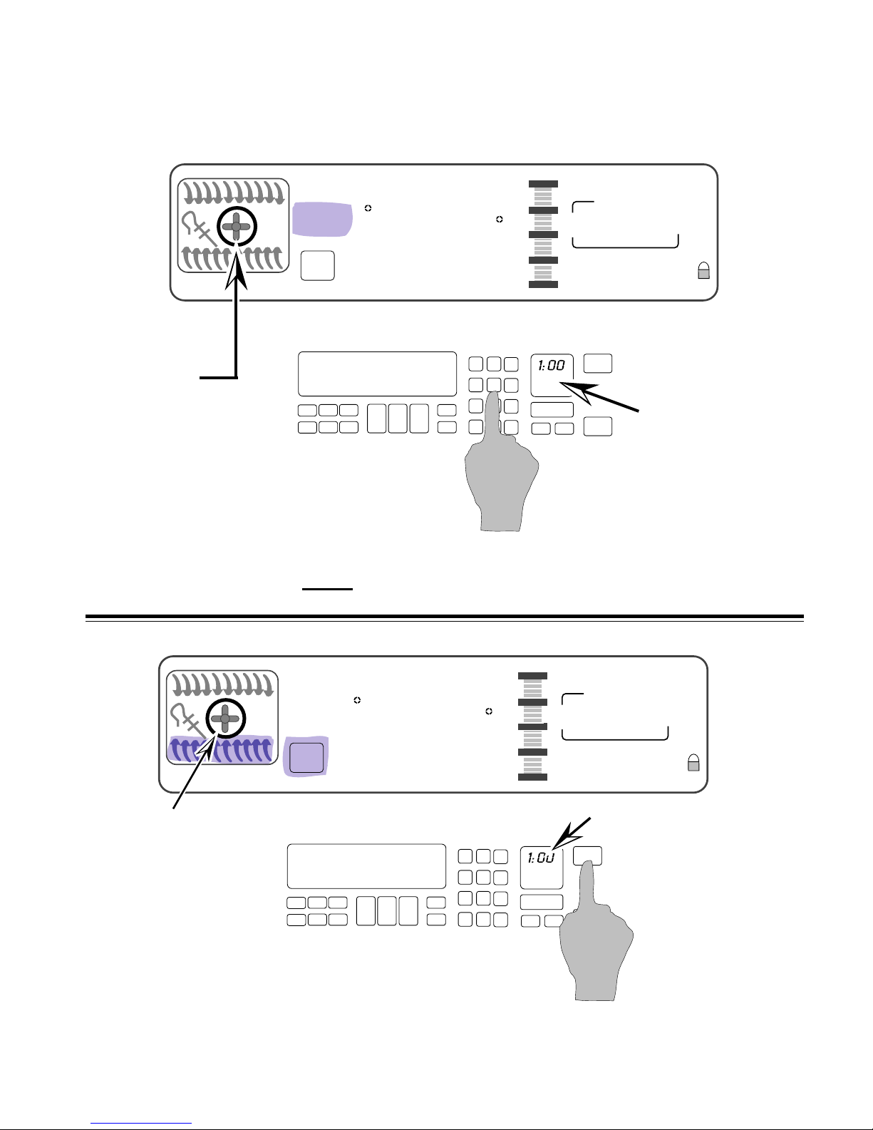
Electronic Range Controls
Easy Convect (Meats)
Temperature adjusted by 25˚
NIGHT LIGHT DELAY
300
DEHYDRATE CONVECTION
ON
EASYCONVECT
NOTE:
Ring element used
on electric models
only.
ENTER STANDARD COOK TIME
COOK TEMP CLEAN TIME
F
Convection Cooking Time adjusted by 20%
SET PROBE TEMP
RAISING
BREAD
CONVECTION MODELS
48
#1 #2 #3
#4 #5 #6
#7 #8 #9
#0
#12
OVEN
LIGHT
START
1:00
CHECK
FOOD AT
CLOSE CONTROL LOCK
DOOR LOCKED START ?
START
CANCEL
1:48
OFF
TIME
STOP
TIME
Press “Start”
After the Start button is pressed, the control
adjusts the convection cooking time by 20%
and the temperature by 25-degrees.
- 11 -
Electronic Range Controls
Sabbath Mode
• Allows the consumer to meet the “No Work” requirements
of the Jewish Sabbath. This means that:
– The range will operate nonstop as long as power is applied to
the range bypassing the 12-hour shutdown default.
– The range will resume cooking if there is a power failure while in
this mode of operation (convection models will resume the “Favorite Cycle”).
• No tones will sound when in this mode.
• Touchpad responses are delayed by 1-second to prevent
accidentally turning the range off.
EASYCONVECT
NOTE:
Ring element used
on electric models
only.
NIGHT LIGHT DELAY
350
ON
Bake
F
DEHYDRATE CONVECTION
ENTER STANDARD COOK TIME
COOK TEMP CLEAN TIME
Use the Sabbath mode with
SET PROBE TEMP
RAISING
BREAD
8:88
#1 #2 #3
#4 #5 #6
#7 #8 #9
#12
START
18:88
START
CANCEL
OFF
18:88
CHECK
FOOD AT
CLOSE CONTROL LOCK
DOOR LOCKED START ?
OVEN
#0
LIGHT
TIME
STOP
TIME
the BAKE function only
- 12 -
Electronic Range Controls
Sabbath Mode
START
TIME
STOP
TIME
Time of Day
EASYCONVECT
NOTE:
Ring element used
on electric models
only.
NIGHT LIGHT DELAY
SET PROBE TEMP
3 7 5
ON
RAISING
F
BREAD
DEHYDRATE CONVECTION
ENTER STANDARD COOK TIME
COOK TEMP CLEAN TIME
8:88
#12
#1 #2 #3
#4 #5 #6
#7 #8 #9
#0
18:88
18:88
CHECK
FOOD AT
CLOSE CONTROL LOCK
DOOR LOCKED START ?
START
OVEN
LIGHT
CANCEL
OFF
CONVECTION MODELS
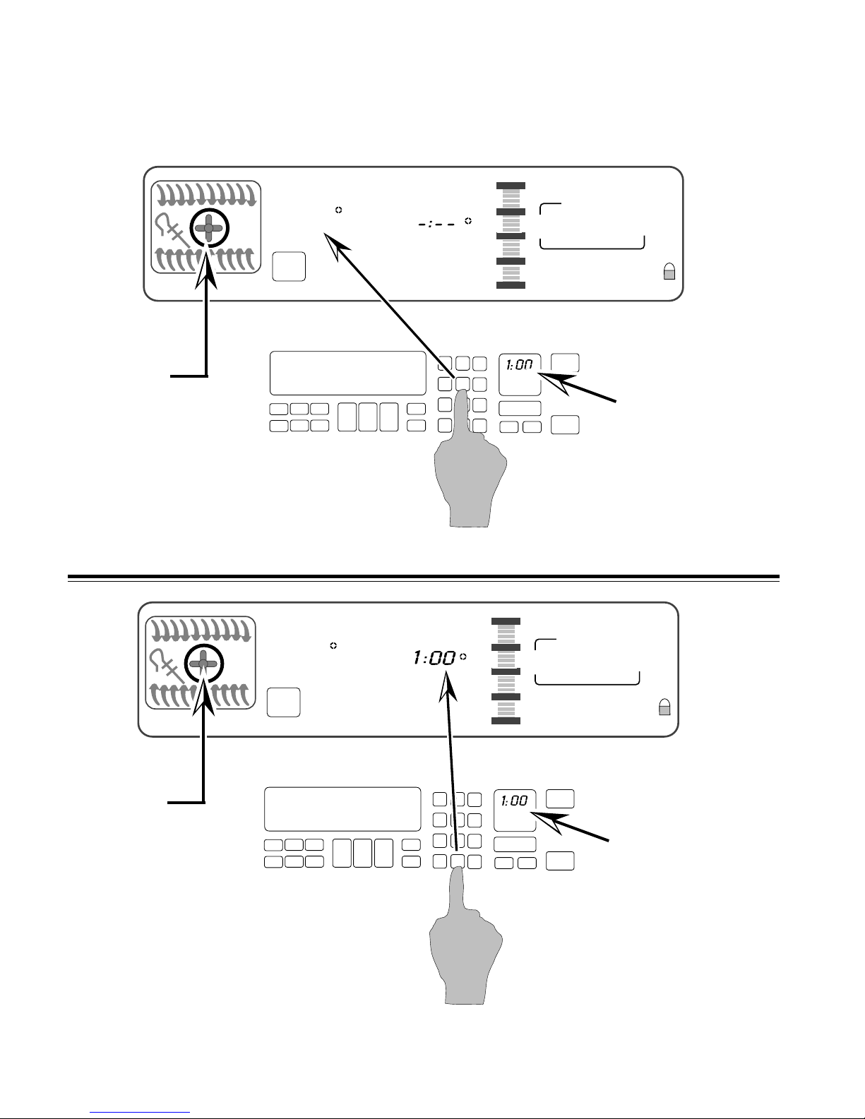
Set the temperature you desire to use during the Sabbath
Mode. We will use
375˚.
NIGHT LIGHT DELAY
SET PROBE TEMP
3 7 5
ON
EASYCONVECT
RAISING
F
BREAD
DEHYDRATE CONVECTION
ENTER STANDARD COOK TIME
COOK TEMP CLEAN TIME
NOTE:
Ring element used
on electric models
only.
CONVECTION MODELS
Select “Start” and the oven will preheat.
8:88
#1 #2 #3
#4 #5 #6
#7 #8 #9
#12
- 13 -
START
18:88
18:88
CHECK
FOOD AT
CLOSE CONTROL LOCK
DOOR LOCKED START ?
TIME
STOP
TIME
Time of Day
START
OVEN
#0
LIGHT
CANCEL
OFF
Electronic Range Controls
Sabbath Mode
NIGHT LIGHT DELAY
SET PROBE TEMP
3 7 5
ON
EASYCONVECT
RAISING
F
BREAD
DEHYDRATE CONVECTION
ENTER STANDARD COOK TIME
COOK TEMP CLEAN TIME
8:88
CONVECTION MODELS
NOTE:
Ring element used
on electric models
only.
#1 #2 #3
#4 #5 #6
#7 #8 #9
#0
#12
OVEN
LIGHT
START
18:88
START
CANCEL
OFF
18:88
Time of Day
CHECK
FOOD AT
CLOSE CONTROL LOCK
DOOR LOCKED START ?
TIME
STOP
TIME
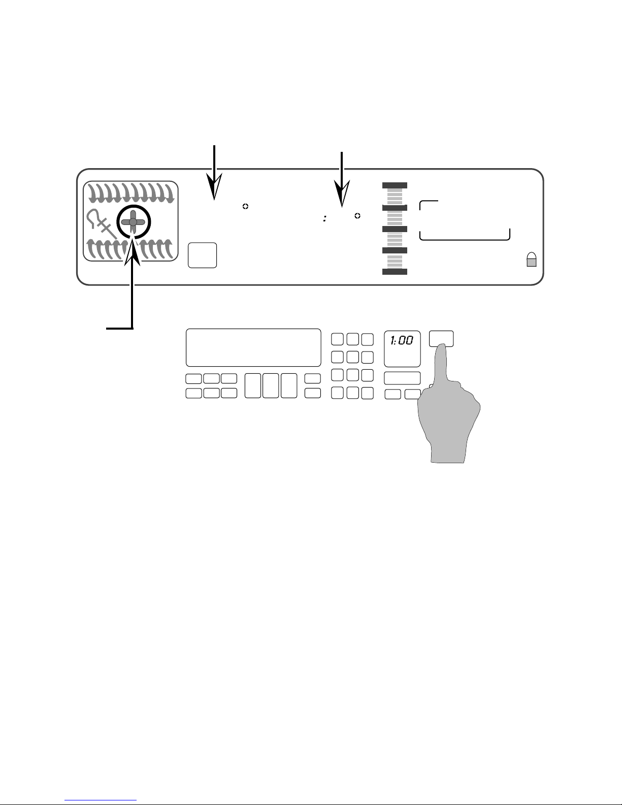
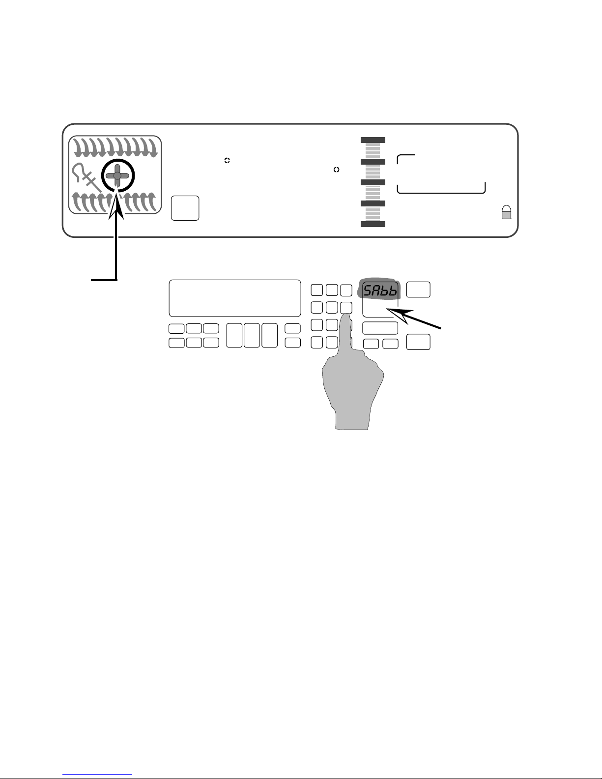
• When the oven has finished preheating, press and hold
the #6 keypad for 5-seconds.
• The Time of Day display changes to “SAbb.”
• The Sabbath Mode can only be cancelled by pressing and
holding the #6 keypad.
- 14 -
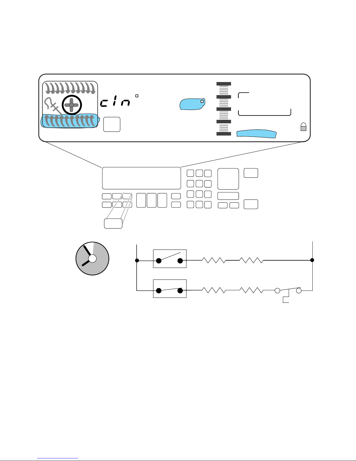
Electronic Range Controls
Clean Mode
EASYCONVECT
NIGHT LIGHT DELAY
SET PROBE TEMP
RAISING
F
BREAD
DEHYDRATE CONVECTION
ON
ENTER STANDARD COOK TIME
COOK TEMP CLEAN TIME
Clean
3:30
#1 #2 #3
#4 #5 #6
#7 #8 #9
#12
4:30
CHECK
FOOD AT
CLOSE CONTROL LOCK
DOOR LOCKED START ?
OVEN
#0
LIGHT
CANCEL
8:00
START
OFF
START
TIME
STOP
TIME
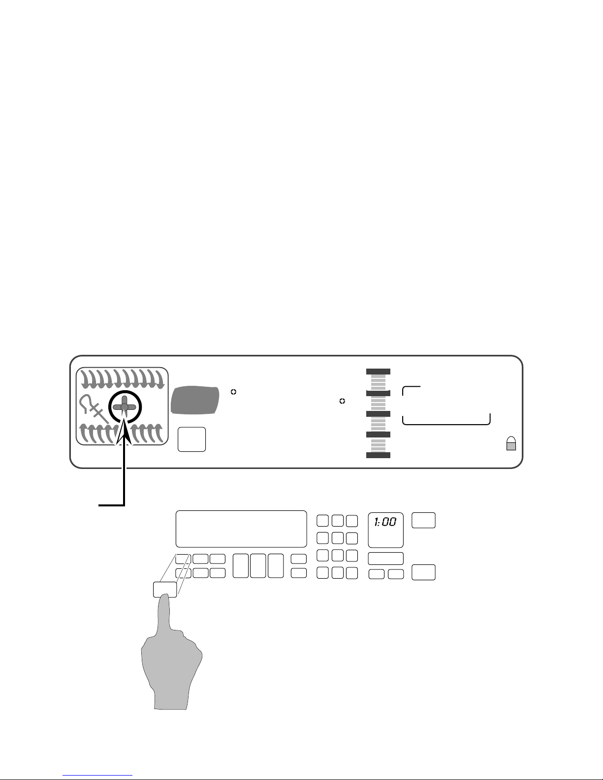
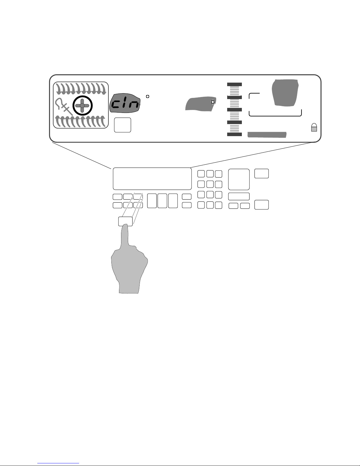
The customer selects the “Clean Mode” on the touch panel.
The 3-
1
/2 hour default clean time will be displayed (the cus-
tomer can select a clean cycle of between 2-
The Start and Stop times will be displayed (based on the time
selected by the customer).
- 15 -
1
/2 and 4-1/2 hours).
Electronic Range Controls
Clean Mode
EASYCONVECT
12
11
10
9
8
7
6
NIGHT LIGHT DELAY
SET PROBE TEMP
RAISING
F
BREAD
DEHYDRATE CONVECTION
ON
Clean
ENTER STANDARD COOK TIME
COOK TEMP CLEAN TIME
1
2
L1
3
4
5
3:30
#1 #2 #3
#4 #5 #6
#7 #8 #9
#12
P6
#0
Ignitor
OVEN
LIGHT
Broil
4:30
CHECK
FOOD AT
CLOSE CONTROL LOCK
DOOR LOCKED START ?
CANCEL
Broil
Valve
8:00
START
OFF
START
TIME
STOP
TIME
N
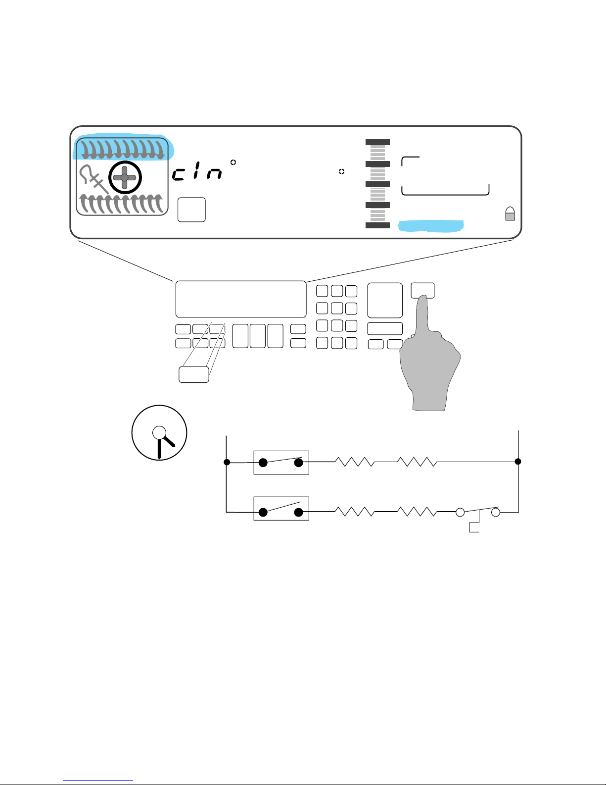
At the instant of start:
• The door will lock.
• The Broil Ignitor is ON.
• The Broil Valve is ON.
• The oven will start heating.
- 16 -
P11
Bake
Ignitor
Bake
Valve
Electronic Range Controls
Clean Mode
EASYCONVECT
12
11
10
9
NIGHT LIGHT DELAY
SET PROBE TEMP
RAISING
F
BREAD
DEHYDRATE CONVECTION
ON
Clean
1
ENTER STANDARD COOK TIME
COOK TEMP CLEAN TIME
L1
2
3
3:00
#1 #2 #3
#4 #5 #6
#7 #8 #9
#12
P6
#0
Broil
Ignitor
OVEN
LIGHT
4:30
CHECK
FOOD AT
CLOSE CONTROL LOCK
DOOR LOCKED START ?
START
CANCEL
Broil
Valve
8:00
OFF
START
TIME
STOP
TIME
N
8
7
6
4
5
After 30-minutes:
• The Bake Ignitor is ON.
• The Bake Valve is ON.
• The Broil Circuit is OFF.
P11
Bake
Ignitor
Bake
Valve
- 17 -
Electronic Range Controls
Clean Mode
EASYCONVECT
12
11
10
9
NIGHT LIGHT DELAY
SET PROBE TEMP
RAISING
F
BREAD
DEHYDRATE CONVECTION
ON
Clean
1
ENTER STANDARD COOK TIME
COOK TEMP CLEAN TIME
L1
2
3
:05
#1 #2 #3
#4 #5 #6
#7 #8 #9
#12
P6
#0
OVEN
LIGHT
Broil
Ignitor
4:30
CHECK
FOOD AT
CLOSE CONTROL LOCK
DOOR LOCKED START ?
CANCEL
Broil
Valve
8:00
START
OFF
START
TIME
STOP
TIME
N
8
7
6
4
5
P11
Bake
Ignitor
Bake
Valve
After approximately 3-hours:
• The display shows that the clean time remaining is
5-minutes.
- 18 -
Electronic Range Controls
Clean Mode
EASYCONVECT
12
11
10
9
NIGHT LIGHT DELAY
SET PROBE TEMP
RAISING
8:88
ON
Clean
1
F
BREAD
DEHYDRATE CONVECTION
ENTER STANDARD COOK TIME
COOK TEMP CLEAN TIME
L1
2
3
8:88
#1 #2 #3
#4 #5 #6
#7 #8 #9
#12
P6
#0
OVEN
LIGHT
Broil
Ignitor
8:88
CHECK
FOOD AT
CLOSE CONTROL LOCK
DOOR LOCKED START ?
START
CANCEL
Broil
Valve
8:88
OFF
START
TIME
STOP
TIME
N
8
7
6
4
5
P11
Bake
Ignitor
Bake
Valve
When the Clean Cycle ends:
• The oven door will remain locked.
• The display will show “locked” for as long as the oven is
hot.
- 19 -
Electronic Range Controls
Clean Mode
EASYCONVECT
12
11
10
9
NIGHT LIGHT DELAY
SET PROBE TEMP
RAISING
8:88
ON
Clean
1
F
BREAD
DEHYDRATE CONVECTION
ENTER STANDARD COOK TIME
COOK TEMP CLEAN TIME
L1
2
3
8:88
#1 #2 #3
#4 #5 #6
#7 #8 #9
#12
P6
OVEN
#0
LIGHT
Broil
Ignitor
8:88
CHECK
FOOD AT
CLOSE CONTROL LOCK
DOOR LOCKED START ?
START
CANCEL
Broil
Valve
8:88
OFF
START
TIME
STOP
TIME
N
8
7
6
4
5
P11
Bake
Ignitor
Bake
Valve
After approximately 45-minutes:
• The oven door will unlock.
• The oven door “locked” display will turn off when the
oven temperature is below 600˚F.
- 20 -

Things To Know
• Replacement service controls must be programmed to
meet the range configuration they are being used in. Failure to do so will result in an F-code (F1 - E3).
Program Procedure
Press the following keypad sequence after the unit has been
powered up.
Convection Freestanding/Slide In:
- Convection Broil
- Clean
- Baked Goods
- Stop Time
- #1, #9, #0
- Timer Set
- Start
- Cancel
Non-Convection Freestanding/Slide In:
- Clean
- Stop Time
- #0
- Oven Light
- #1
- Start
- Cancel
This will set the board for the proper range configuration.
NOTE: These program sequences also check all the capacitive
glass touchpad keys. If the sequence does not work, unplug
the unit, wait 10-seconds, plug the unit back in, and rerun the
sequence from the “PF” mode.
- 21 -

Things To Know (Cont’d)
• On gas models only, the conmvection fan is delay-started
1-minute for any convection cook cycle.
• On gas models the convection fan cycles on and off during operation.
— On for 10-seconds and off for 20-seconds in convection broil.
— On for 30-seconds and off for 1-seconds in convection bake/
roast.
• The convection fan stops running if the oven door is
opened.
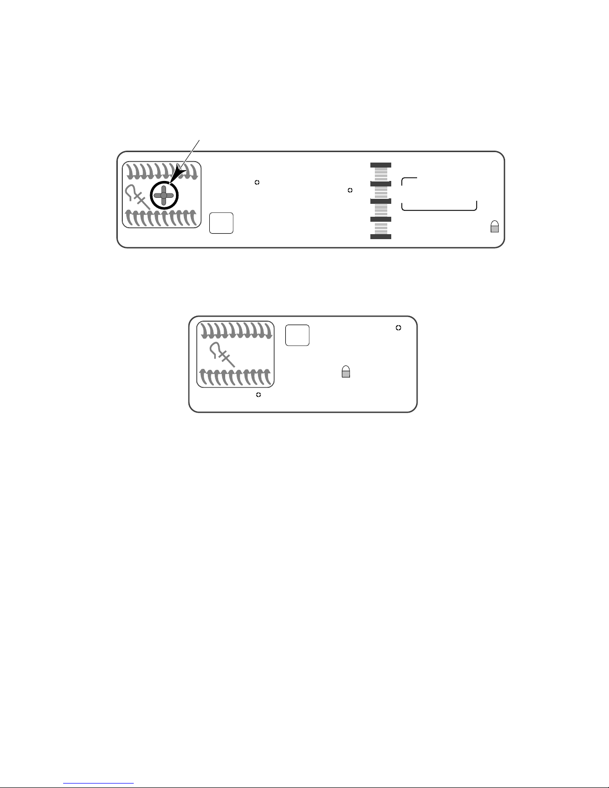
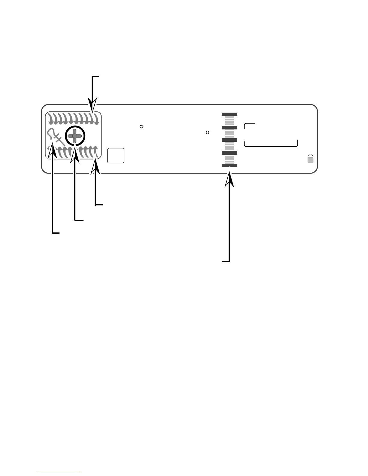
• The temperature sensor mounting screw is removed from
the rear on freestanding models, and from the front on
slide-in models.
• The gas shut-off lever is located on the gas safety valve.
• All gas models are shipped with the LP conversions ori-
fice kit Part #9751844 packed with the Use & Care
materials. The kit consists of the following:
(2) 6" burner spuds
(2) 8" burner spuds
(1) broiler burner spud
- 22 -
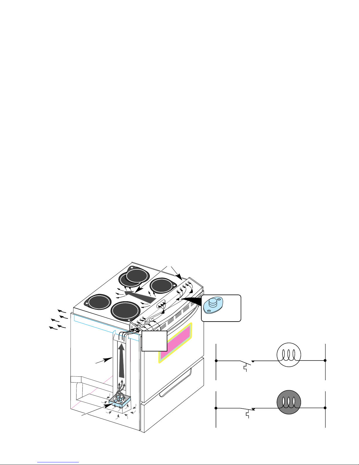
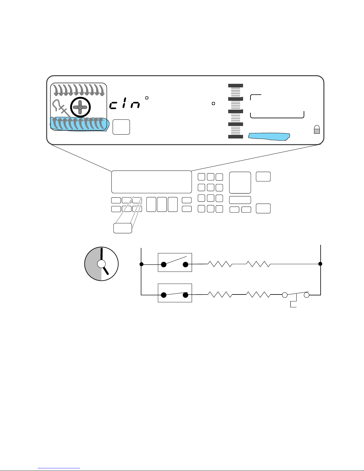
Range Cooling System
L1 N
N
L1
THERMAL
SWITCH
THERMAL
SWITCH
COOLING FAN
“OFF”
COOLING FAN
“ON”
Refer to Figure 3 while you read this section.
• A cooling fan, in the storage drawer area, is used to maintain
optimum temperatures in the console areas.
• Restrictions to the air flow in the cooling systems can cause premature failure of the controls or the thermal protectors.
The cooling fan draws air from inside the base of the cabinet. It
forces the air up the air channel, which is located under the left side
panel, to the opening at the end of the control panel chassis. Air then
flows across the chassis below the control panel, and cools it. Air
enters through the series of holes in front of the range top, flows beneath it, and exits to the outside through slots in the rear panel.
The cooling fan is operated by the cooling fan thermal switch, which
is located under the right side of the control panel, on the control
panel chassis.
When the control panel temperature exceeds 104˚F, the thermal
switch will close and turn ON the cooling fan.
When the control panel chassis temperature drops below the turn-on
point, the thermal switch opens, and turns the cooling fan off.
AIR FLOWS FROM
CONTROL PANEL
UNDER RANGE TOP
AIR FLOWS OUT
REAR PANEL
COOLING
FAN THERMAL
AIR CHANNEL
SWITCH
AIR INLETS
UNDER
CONTROL
PANEL
FIGURE 3
The Cooling System
COOLING FAN
- 23 -
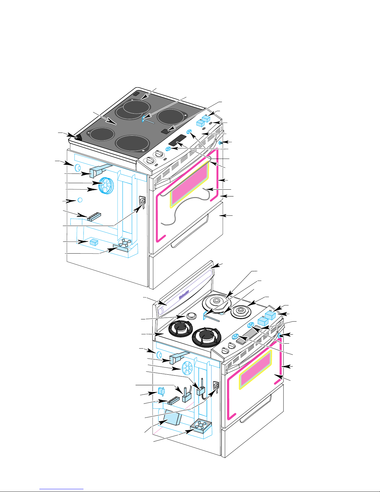
Component Layout
Refer to Figures 4 & 5 for the locations of the individual
components in the electric and gas ranges.
SURFACE ELEMENTS
OVEN TEMPERATURE SENSOR
HOT SURFACE LIGHTS (4)
OVEN VENT
OVEN LIGHT
DOOR LATCH
SOLENOID
CONVECTION FAN
CONVECTION BAKE
ELEMENT
BAKE ELEMENT
SHUTDOWN SWITCH
TERMINAL BLOCK
TEMPERATURE
PROBE SOCKET
DLB RELAY
COOLING FAN
MAINTOP GLASS
HALOGEN
FLUORESCENT
LAMP
OVEN VENT
HALOGEN
INFINITE CONTROLS (4)
INDICATOR LIGHT (4)
CONTROL PANEL
OVEN LIGHT SWITCH
CONTROL PANEL
THERMAL SWITCHES
ELECTRONICS BOARD
BROIL/CONVECTION
ELEMENTS
FIBERGLASS SEAL
BAKE ELEMENT
OVEN DOOR GLASS
STORAGE DRAWER
FIGURE 4
The Electric Range Components
BACKGUARD GLASS
10,000 BTU BURNER/
BEZEL & IGNITOR (2)
OVEN SENSOR
BAKE BURNER SHUTDOWN SWITCH
6,000 BTU BURNER/
BEZEL & IGNITOR (2)
GAS VALVE (4)
CONTROL PANEL
ELECTRONICS BOARD
MAINTOP GLASS
OVEN LIGHT
DOOR LATCH SOLENOID
CONVECTION FAN & ELEMENT
PRESSURE REGULATOR
SAFETY VALVE
BALLAST
TERMINAL BLOCK
TEMPERATURE
PROBE SOCKET
IGNITOR
MODULE
COOLING FAN
- 24 -
OVEN LIGHT SWITCH
COOLING FAN
THERMAL SWITCH
CONTROL PANEL
SHUTDOWN SWITCH
FIBERGLASS OVEN
DOOR SEAL
OVEN DOOR GLASS
FIGURE 5
The Gas Range Components
 Loading...