

Page 1

TK-D740
TK-D740H
TK-D740HV
TK-D840
TK-D840H
TK-D840HU
VHF DIGITAL TRANSCEIVER
UHF DIGITAL TRANSCEIVER
USER MANUAL
B5A‑0925‑00/01
Page 2

Contents
PREPARATION ...................................................................................................................... 4
Connecting the power cable............................................................................................ 4
Installing the Transceiver ................................................................................................. 4
ORIENTATION ....................................................................................................................... 6
FRONT AND REAR VIEWS ............................................................................................... 6
DISPLAY ............................................................................................................................. 8
PROGRAMMABLE FUNCTIONS ........................................................................................ 11
BASIC OPERATION ............................................................................................................ 15
SWITCHING POWER ON/ OFF ....................................................................................... 15
Transceiver Password ................................................................................................... 15
ADJUSTING THE VOLUME ............................................................................................. 15
SELECTING A ZONE AND CHANNEL ............................................................................ 15
TRANSMITTING ............................................................................................................... 15
RECEIVING ...................................................................................................................... 16
Receiving Group Calls .................................................................................................. 16
Receiving Individual Calls ............................................................................................. 16
FleetSync: ALPHANUMERIC 2-WAY PAGING FUNCTION ............................................... 17
SELCALL (SELECTIVE CALLING) .................................................................................. 17
Transmitting ................................................................................................................... 17
Receiving ...................................................................................................................... 17
Identification Codes ...................................................................................................... 17
PAGING CALL .............................................................................................................. 17
SCAN ................................................................................................................................... 18
PRIORITY SCAN .............................................................................................................. 18
TEMPORARY CHANNEL LOCKOUT ............................................................................... 18
SCAN DELETE/ ADD ....................................................................................................... 18
DTMF CALLS ...................................................................................................................... 19
MANUAL DIALING ........................................................................................................... 19
AUTODIAL ........................................................................................................................ 19
REDIALING ...................................................................................................................... 19
2
Page 3

ADVANCED OPERATIONS ................................................................................................. 20
EMERGENCY CALLS ...................................................................................................... 20
Lone Worker Mode ........................................................................................................ 20
SCRAMBLER ................................................................................................................... 21
MONITOR/ SQUELCH OFF ............................................................................................. 21
Squelch Level ................................................................................................................ 22
PUBLIC ADDRESS (PA) .................................................................................................. 22
HORN ALERT .................................................................................................................. 22
GPS REPORT .................................................................................................................. 22
DMR ..................................................................................................................................... 23
INDIVIDUAL/GROUP CALLS ........................................................................................... 23
Receiving ...................................................................................................................... 23
BACKGROUND OPERATIONS ........................................................................................... 24
TIME-OUT TIMER (TOT) .................................................................................................. 24
AUXILIARY PORT ............................................................................................................ 24
DISPLAY BRIGHTNESS .................................................................................................. 24
BUSY CHANNEL LOCKOUT (BCL) ................................................................................. 24
PTT ID .............................................................................................................................. 25
SIGNALING ..................................................................................................................... 25
COMPANDER ................................................................................................................... 25
VOICE ANNUNCIATION ................................................................................................... 25
3
Page 4
PREPARATION
WARNING
Various electronic equipment in your vehicle may malfunction if they are not properly protected
from the radio frequency energy which is present while transmitting. Typical examples include
electronic fuel injection, anti-skid braking, and cruise control. If your vehicle contains such
equipment, consult the dealer for the make of vehicle and enlist his/her aid in determining if they
will perform normally while transmitting.
Connecting the power cable
CAUTION
The transceiver operates in 12 V negative ground systems only! Check the battery polarity and
voltage of the vehicle before installing the transceiver.
1 Check for an existing hole, conveniently located in the firewall, where the
power cable can be passed through.
• If no hole exists, use a circle cutter to drill a hole, then install a rubber
grommet.
2 Run the power cable through the firewall and into the engine compartment.
3 Connect the red lead to the positive (+) battery terminal and the black lead to
the negative (–) battery terminal.
• Place the fuse as close to the battery as possible.
4 Coil the surplus cable and secure it with a retaining band.
• Be sure to leave enough slack in the cables so the transceiver can be
removed for servicing while keeping the power applied.
Installing the Transceiver
WARNING
For passenger safety, install the transceiver securely using the supplied mounting bracket and
screw set so the transceiver will not break loose in the event of a collision.
Note:
◆ Before installing the transceiver, check how far the mounting screws will extend below
the surface. When drilling mounting holes, be careful not to damage vehicle wiring or
parts.
1 Mark the position of the holes in the dash, using the mounting bracket as a
template. Using a 4.2 mm (5/32 inch) drill bit, drill the holes, then attach the
mounting bracket using the supplied screws.
• Mount the transceiver within easy reach of the user and where there is
sufficient space at the rear of the transceiver for cable connections.
2 Connect the antenna and the supplied power cable to the transceiver.
4
Page 5
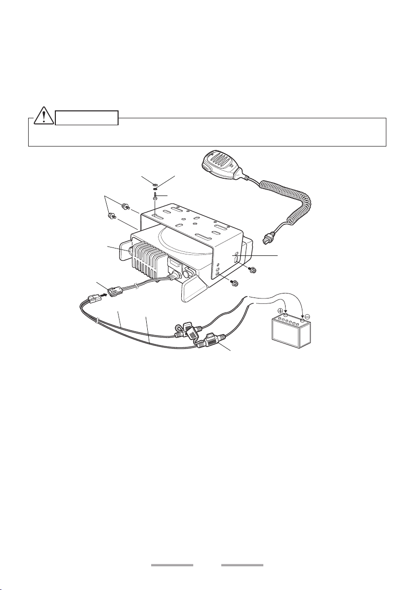
3 Slide the transceiver into the mounting bracket and secure it using the supplied
hex-headed screws.
4 Mount the microphone hanger in a location where it will be within easy reach
of the user.
• The microphone and microphone cable should be mounted in a place
where they will not interfere with the safe operation of the vehicle.
CAUTION
When replacing the fuse in the DC power cable, be sure to replace it with a fuse of the same value.
Never replace a fuse with one that is rated with a higher value.
M4 x 8 mm
Hex-headed screw
Antenna connector
Power input
connector
DC power cable
Flat
washer
Black (–) cable
Red (+) cable
Spring
washer
5 x 16 mm Self-tapping
screw
Microphone
Mounting bracket
12 V vehicle
battery
Fuse
5
Page 6
ORIENTATION
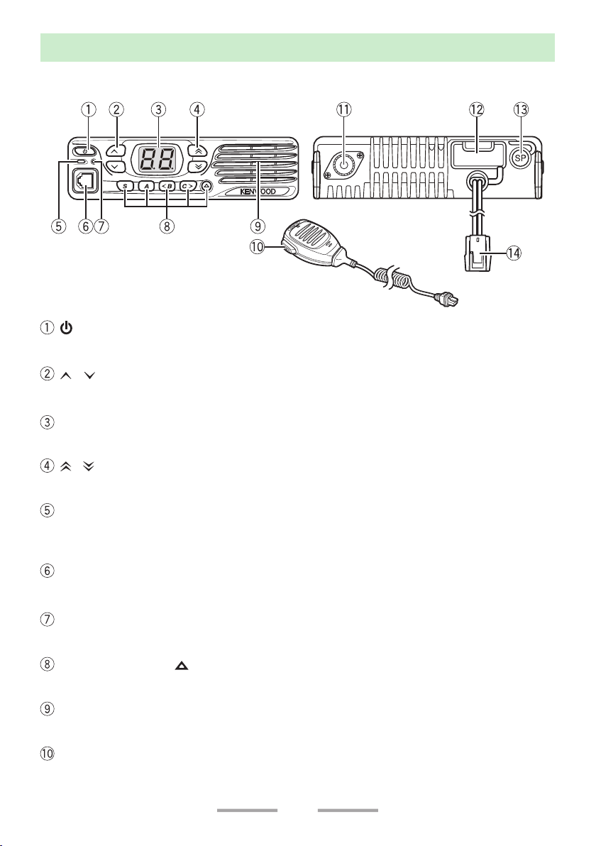
FRONT AND REAR VIEWS
(Power) switch
Press to switch the transceiver ON or OFF.
/ keys
Press to activate their programmable functions.
Display
Refer to page 8.
/ keys
Press to activate their programmable functions.
ACC.
TX/RX Indicator
Lights red while transmitting. Lights green while receiving a signal. Flashes
orange when receiving an optional signaling call.
Microphone jack
Insert the microphone plug into this jack.
Status Indicator
Lights during a specified mode, based on dealer programming.
S / A / <B / C> / keys
Press to activate their programmable functions.
Speaker
Internal speaker.
PTT switch
Press this switch, then speak into the microphone to call a station.
6
Page 7

Antenna connector
Connect the antenna to this connector.
ACC connector
Connect the ACC to this connector, via the KCT-60.
External speaker jack
Connect an external speaker to this jack.
Power input connector
Connect the DC Power Cable to this connector.
7
Page 8
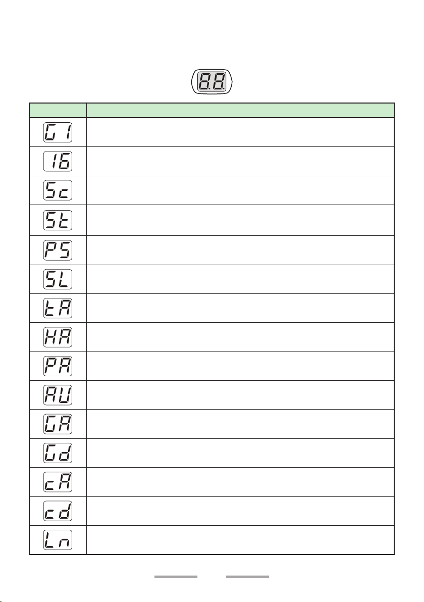
DISPLAY
The display shows the zone/ channel number and the left and right dots show
various modes of operation.
Display
Description
Zone Display (Zone 1)
Channel Display (Channel 16)
Appears during Scan. (Sc)
Appears during the transceiver is stunned. (St)
Appears when switch the transceiver ON.
The Transceiver Password function is programmed. (PS)
Appears when the Squelch Level setting is activated. (SL)
Appears when the Talk Around function is activated. (tA)
Appears when the Horn Alert function is activated. (HA)
Appears when the Public Address function is activated. (PA)
Appears when the AUX function is activated. (AU)
Appears when a zone is added to the scan list. (GA)
Appears when a zone is removed from the scan list. (Gd)
Appears when a channel is added to the scan list. (cA)
Appears when a channel is removed from the scan list. (cd)
Appears when the Lone Worker function is activated. (Ln)
8
Page 9

Display
Description
Appears during Send Data. (dt)
Appears during the channel is busy.
The selected channel is the Priority channel 1. (P1)
The selected channel is the Priority channel 2. (P2)
The selected channels are the Priority channel 1 and 2. (PP)
Appears when the Scrambler function is activated. (Sr)
Appears when the Scrambler code mode is activated. (co)
Appears when the Message is completed. (Ed)
Appears when the Call Interrupt function is activated. (It)
Appears when the External Speaker is selected. (SP)
Appears when the Key Lock function is activated. (Lc)
Emergency Status/ Lone Worker Status/ Man down Status/
Stationary Status/ Motion Status. (EG)
Appears when the Autodial mode. (Ad)
Appears when the Home channel. (Hc)
Appears during the Broadcast group call. (bc)
Appears when the Priority-channel select mode. (Pr)
Appears when the OVCM function is activated. (oc)
The left and right dots on the display can be programmed to indicate specific
9
Page 10

modes of operation, as listed below.
• AUX
• External Speaker
• Horn Alert
• Lone Worker
• Public Address
• Scan Delete/Add
• Scrambler
• Talk Around
• Priority Channel
The right dot will blink during special operations, as listed below.
• Scrambler Code
• Squelch Level
• Channel Entry
10
Page 11

PROGRAMMABLE FUNCTIONS
The , , , , S, A, <B, C>, and keys can be programmed with the functions
listed below. Ask your dealer for details on these functions.
Note:
◆ The duration of pressing a key to activate a function is dependent on your dealer
setting. Your dealer may have set some keys to be held down for a short duration
instead of being momentarily pressed. Ask your dealer for details on which keys need
to be held down to activate their functions.
n None
No function has been programmed.
n Autodial
Autodial allows you to make a private DTMF call to another party.
n AUX
Activate the auxiliary port. The auxiliary port is used with optional boards.
n Broadcast
Toggles the call type between Broadcast Call and Conference Call.
n Call 1/ Call 2
Initiates a call on the selected channel.
n Call Interruption
Interrupts a call, stopping it from being received.
n Channel Down
Decreases the Channel number in steps of 1.
n Channel Down (Continuous)
Hold down this key to continuously decrease the Channel number.
n Channel Entry
Selects the channel number.
n Channel Up
Increases the Channel number in steps of 1.
n Channel Up (Continuous)
Hold down this key to continuously increase the Channel number.
11
Page 12

n Emergency
Places the transceiver into Emergency mode. Emergency mode is used to carry
out emergency actions.
Note:
◆ This function can be programmed only on the key.
n Home Channel
Press this key to immediately select your home channel.
n Home Channel Select
Hold down this key to set the current channel as the Home Channel.
n Fixed Volume
Cycles the various tone levels of the transceiver between low, high, and off.
n External Speaker
Toggles Optional External Speaker ON and OFF.
n Horn Alert
Enables the Horn Alert terminal when a call is received. It activates the car
headlights and horn to alert you of the incoming call when you are away from the
transceiver.
n LED Brightness
Adjust the he display brightness between High, Low, and Off.
n Lone Worker
Toggles Lone Worker mode ON and OFF.
n Monitor
Turns the transceiver signaling off, to listen to all calls that are received on the
channel. Press this key again to turn the transceiver signaling back on.
n Monitor Momentary
Turns the transceiver signaling off while holding down this key. Release this key to
turn the transceiver signaling back on. While signaling is off, you can listen to all
calls that are received on the channel.
n OVCM
Toggles OVCM (Open Voice Channel Mode) between ON and OFF.
n Paging Call
To transmit your PTT ID list, to request a call.
n Priority-channel Select
Enters the Priority-channel Select mode.
12
Page 13

n Public Address
The PA system can only be used with an optional relay unit and external speaker.
n Scan
Press this key to start scanning the transceiver channels.
n Scan Delete/Add
Adds or removes the selected Channel to or from the scan sequence.
n Scrambler
Toggles the Scrambler function ON and OFF. Hold this key to enter Scrambler
Code mode, to change the Privacy List number. Hold the key again exit Scrambler
Code mode. Additionally, the Privacy List becomes the Scrambler List.
Note:
◆ This function cannot be used in certain countries. Contact your KENWOOD dealer for
further information.
n Send the GPS data
Manually sends your GPS data to the base station.
n Squelch Level
Adjusts the transceiver squelch level.
n Squelch Off
Press to hear background noise. Press this key again to return to normal
operation.
n Squelch Off Momentary
Hold down this key to hear background noise. Release this key to return to normal
operation.
n Talk Around
Toggle Talk Around function ON and OFF. Talk Around function allows you to
communicate directly with other transceivers, without the use of a repeater.
n Volume Down
Decreases the Volume level in steps of 1.
n Volume Down (Continuous)
Hold down this key to continuously decrease the Volume level.
n Volume Up
Increases the Volume level in steps of 1.
n Volume Up (Continuous)
Hold down this key to continuously increase the Volume level.
13
Page 14

n Zone Delete/Add
Toggles the Zone status between deleted and added.
n Zone Down
Decreases the zone number in steps of 1.
n Zone Down (Continuous)
Hold down this key to continuously decrease the Zone number.
n Zone Up
Increases the zone number in steps of 1.
n Zone Up (Continuous)
Hold down this key to continuously increase the Zone number.
14
Page 15

BASIC OPERATION
SWITCHING POWER ON/ OFF
Press [ ] to switch the transceiver ON.
Press [
] again to switch the transceiver OFF.
Transceiver Password
If the Transceiver Password function is programmed, “PS” will appear on the
display when the power is turned ON.
To enter the password:
1 Press
• When using an optional microphone with a keypad, simply enter the
2 Press S or
• Press A or # to delete an incorrect digit. Press and hold A or # to delete all
• Repeat steps 1 and 2 to enter the entire password.
3 Press S or
• If you enter an incorrect password, the transceiver remains locked.
/ to select a digit.
password digits and proceed to step 3.
to accept the entered digit and move to the next digit.
digits.
to confirm the password.
ADJUSTING THE VOLUME
Press the key programmed as [Volume Up] to increase the volume. Press the
key programmed as [Volume Down] to decrease the volume.
SELECTING A ZONE AND CHANNEL
Select the desired zone and channel using the keys programmed as [Zone Up]/
[Zone Down] and [Channel Up]/ [Channel Down].
• “G1” (Zone 1)/ “16” (Channel 16) appears on the display.
TRANSMITTING
1 Select the desired zone and channel.
2 Press the key programmed as [Monitor] or [Squelch Off] to check whether or
not the channel is free.
• If the channel is busy, wait until it becomes free.
3 Press the PTT switch and speak into the microphone. Release the PTT switch
to receive.
• For best sound quality at the receiving station, hold the microphone
approximately 1.5 inches (3 cm to 4 cm) from your mouth.
15
Page 16

RECEIVING
Select the desired zone and channel. If signaling has been programmed on the
selected channel, you will hear a call only if the received signal matches your
transceiver settings.
Receiving Group Calls
When you receive a group call and the received group ID matches the ID set up
on your transceiver, you can hear the caller’s voice.
Receiving Individual Calls
When you receive an individual call, a ringing tone will sound. To respond to the
call, press and hold the PTT switch and speak into the transceiver as you would
during a normal transmission.
16
Page 17

FleetSync: ALPHANUMERIC 2-WAY PAGING FUNCTION
FleetSync is an Alphanumeric 2-way Paging Function and is a protocol owned by
JVC KENWOOD Corporation.
SELCALL (SELECTIVE CALLING)
A Selcall is a voice call to a particular station or to a group of stations.
Transmitting
1 Select your desired zone and channel.
2 Press the PTT switch to transmit your PTT ID list and begin your conversation.
Receiving
If enabled by your dealer, an alert tone will sound and the LED will blink when a
Selcall has been received.
To respond to the call, press the PTT switch and speak into the microphone.
Identification Codes
An ID code is a combination of a 3-digit Fleet number and a 4-digit ID number.
Each transceiver must have its own Fleet and ID number.
Note:
◆ The ID range may be limited by programming.
PAGING CALL
1 Select your desired zone and channel.
2 Press the key programmed as [Paging Call] to transmit your PTT ID list, to
request a call.
17
Page 18

SCAN
Scan monitors for signals on the transceiver channels. While scanning, the
transceiver checks for a signal on each channel and only stops if a matching
signal is present.
To start/ stop scanning, press the key programmed as [Scan].
• “Sc” appears on the display during Scan.
• When a signal is detected, Scan pauses at that channel. The transceiver will
remain on the busy channel until the signal is no longer present, at which time
Scan resumes.
Note:
◆ To use Scan, there must be at least 2 channels added to the scanning sequence.
PRIORITY SCAN
If a Priority channel has been programmed, the transceiver will automatically
change to the Priority channel when a call is received on that channel, even if call
is being received on a normal channel.
• “P1” appears on the display to indicate the Priority channel 1.
• “P2” appears on the display to indicate the Priority channel 2.
• “PP” appears on the display to indicate the Priority channels 1 and 2.
TEMPORARY CHANNEL LOCKOUT
During scan, you can temporarily remove specific channels from the scanning
sequence by pressing the key programmed as [Scan Delete/Add] while Scan is
paused at the undesired channel.
• The channel is no longer scanned. However, when scanning is ended and
restarted, the Scan settings return to normal.
SCAN DELETE/ ADD
You can add and remove zones and/or channels to and from your scan list.
1 Select your desired zone and/or channel.
2 Press the key programmed as [Zone Delete/Add] (to add/remove zones) or
[Scan Delete/Add] (to add/remove channels).
• When a zone is added to scan, “GA” appears on the display. When it is
removed, “Gd” appears on the display.
• When a channel is added to scan, “cA” appears on the display. When it is
removed, “cd” appears on the display.
18
Page 19

DTMF CALLS
Note:
◆ For keypad operation, you must use an optional microphone with a keypad.
MANUAL DIALING
1 Press and hold the PTT switch.
2 Enter the desired digits using the keypad.
• If Keypad Auto-PTT is enabled by your dealer, you do not need to press
the PTT switch to transmit; you can make the call simply by pressing the
keys.
AUTODIAL
Autodial allows you to quickly call DTMF numbers that have been programmed
onto your transceiver.
1 Press the key programmed as [Autodial].
• “Ad” appears on the display.
2 Press the
number directly (1 ~ 9)
• “A1” (Autodial list 1) appears on the display.
3 Press the PTT switch to make the call.
/ key to select your desired Autodial list number, or enter the list
REDIALING
1 Press the key programmed as [Autodial].
• “Ad” appears on the display.
2 Press the 0 key.
• “rd” appears on the display.
• If there is no data in the redial memory, an error tone will sound.
3 Press the PTT switch to make the call.
Note:
◆ Switching the transceiver power OFF clears the redial memory.
19
Page 20

ADVANCED OPERATIONS
EMERGENCY CALLS
If your transceiver has been programmed with the Emergency function, you can
make emergency calls.
1 Press and hold the key programmed as [Emergency].
• Ask your dealer for the length of time necessary to hold this key before the
transceiver enters Emergency mode.
• When the transceiver enters Emergency mode, it will change to the
Emergency channel and begin transmitting based on how it is set up by
your dealer.
2 To exit Emergency mode, press the [Emergency] key again.
• If the Emergency mode completes a preset number of cycles, Emergency
mode will automatically end and the transceiver will return to the zone and
channel that was in use before Emergency mode was entered.
Note:
◆ Your dealer can set the transceiver to emit a tone when transmitting in Emergency
mode.
◆ Your dealer can set the transceiver to emit tones and received signals as normal, or
mute the speaker during Emergency operation.
Lone Worker Mode
Lone Worker Mode is a safety feature built into the transceiver. If the transceiver is
not operated for a pre-programmed period of time, the transceiver will emit a tone
and automatically enter Emergency operation.
Press the key programmed as [Lone Worker] to toggle the Lone Worker function
ON or OFF.
• “Ln” appears on the display for 1 second.
20
Page 21

SCRAMBLER
The Scrambler function allows you to hold a conversation in complete privacy.
When activated, any other party listening in on your channel will be unable to
understand your conversation. Press this key to toggle the Scrambler function ON
or OFF.
Press the key programmed as [Scrambler] to toggle the Scrambler function ON
or OFF.
• “Sr” appears on the display for 1 second.
You can change the scrambler codes:
1 Press and hold the key programmed as [Scrambler key].
• “co” (code) appears on the display, followed by the current scrambler code.
2 Press
/ to select your desired scrambler code.
3 Press S, A, C>, or
• After changing your scrambler code, be sure to inform all of your group
members of the new code so they can also reset their transceivers. The
scrambler function will not work with transceivers set up with different
scramble codes.
to store the new setting.
MONITOR/ SQUELCH OFF
You can use the key programmed as [Monitor] or [Squelch Off] to listen to weak
signals that you cannot hear during normal operation and to adjust the volume
when no signals are present on your selected channel.
Your dealer can program a key with one of 4 functions:
• Monitor:
Press to deactivate QT, DQT, FleetSync Signaling, or DMR. Press again to
return to normal operation.
• Monitor Momentary:
Press and hold to deactivate QT, DQT, FleetSync Signaling or DMR. Release
to return to normal operation.
• Squelch Off:
Press to hear background noise. Press again to return to normal operation.
• Squelch Off Momentary:
Press and hold to hear background noise. Release to return to normal
operation.
21
Page 22

Squelch Level
If a key has been programmed as [Squelch Level], you can readjust your
transceiver’s squelch level:
1 Press the key programmed as [Squelch Level].
• “SL” appears on the display, followed by the current squelch level.
2 Press
/ to select the desired squelch level from 0 to 9.
3 Press S, A, C>, or
to store the new setting.
PUBLIC ADDRESS (PA)
The PA system can only be used with an optional relay unit and external speaker.
1 Press the key programmed as [Public Address] to activate the Public Address
function.
• “PA” appears on the display for 1 second.
2 Press and hold the PTT switch, then speak into the microphone to make your
address through the external speaker.
3 Press the [Public Address] key again to exit Public Address.
HORN ALERT
The Horn Alert function can only be used with an optional relay unit.
Press the key programmed as [Horn Alert] to toggle the Horn Alert function ON
or OFF.
• “HA” appears on the display for 1 second.
GPS REPORT
If a GPS unit (NMEA-0183 format) is installed on your transceiver, you can press
the key programmed as [Send the GPS data] to send your location data.
22
Page 23

DMR
DMR is a generic name for a digital communication system protocol utilizing
4-level FSK.
In a DMR Conventional system, communications are realized by sending and
receiving digital signals on a DMR digital channel. Using a DMR ID (Unit ID or
Group ID) allows the various communications
INDIVIDUAL/GROUP CALLS
Each channel is set up with an individual or group ID list number. To make a call,
select the channel with the ID list number you wish to call, then press the PTT
switch to start the call.
• Your dealer may also have set Selcall on PTT for Individual or Group calls,
allowing you to make an Individual or Group call when pressing the PTT
switch.
• To page the target transceiver instead of initiating a voice call, press the key
programmed as [Paging Call].
• If PTT Proceed tone is enabled, the Proceed tone will sound. After the tone
ends, you can being the call.
Receiving
When you receive an individual call, a ringing tone will sound. Respond to the call
by pressing the PTT switch.
• If the auto reset timer expires before you respond to the call, the call will
end. Your dealer can set the duration for the auto reset timer (default is 10
seconds).
When you receive a group call and the received group ID matches the ID set up
on your transceiver, a ringing tone will sound and you can hear the caller’s voice.
23
Page 24

BACKGROUND OPERATIONS
TIME-OUT TIMER (TOT)
The Time-out Timer is used to prevent you from using a channel for an extended
duration. If you continuously transmit for a preset time, the transceiver will stop
transmitting and a warning tone will sound. Release the PTT switch to stop the
tone.
AUXILIARY PORT
Press the key programmed as [AUX] to activate the auxiliary port. The auxiliary
port is used with optional boards.
• “AU” appears on the display for 1 second.
DISPLAY BRIGHTNESS
You can cycle the display brightness between high, low, and off by pressing the
key programmed as [LED Brightness].
BUSY CHANNEL LOCKOUT (BCL)
When activated, BCL prevents you from interfering on a channel that is already
in use. Pressing the PTT switch will cause a warning tone to sound and the
transceiver will not transmit. Release the PTT switch to stop the tone.
Note:
◆ Ask your dealer for an explanation on how BCL functions when using QT, DQT, or
Optional signaling.
If BCL Override has been programmed, you can transmit over the current signal:
1 Press and hold the PTT switch.
• If the channel is already in use, a warning tone will sound.
2 Quickly release and then press the PTT switch again.
3 Speak into the transceiver as you would during a normal call.
24
Page 25

PTT ID
PTT ID is the transceiver unique ID code which is sent each time the PTT switch
is pressed and/or released.
Note:
◆ PTT ID can be made only in analog operation.
SIGNALING
QT/ DQT
The Encoder/Decoder function uses QT/ DQT to segregate talk groups, so users
only hear calls from their own group.
DTMF
A DTMF PTT ID is included for dispatch operations or simple remote control
applications. The DTMF decode capabilities include Selective Call ID, Transpond
with ID, and “Wild Card” Group Calling.
2-Tone
2-tone Signaling opens the squelch only when your transceiver receives a call
containing matching 2 tones.
5-Tone
5-tone Signaling opens the squelch only when the transceiver receives the 5
tones programmed in your transceiver. Transceivers that do not transmit the
correct tones will not be heard.
COMPANDER
If programmed by your dealer for a channel, the compander will remove excessive
noise from transmitted signals, to provide higher clarity of signals.
Note:
◆ The compander is used only in analog operation.
VOICE ANNUNCIATION
If enabled by your dealer, when changing the zone and channel, an audio voice
will announce the new zone and channel number.
25
Page 26

© 2016
 Loading...