

Page 1

TK-90
HF TRANSCEIVER
INSTRUCTION MANUAL
TRANSCEPTOR HF
MANUAL DE INSTRUCCIONES
短波对讲机
使用说明书
© B62-1866-10 (M)
09 08 07 06 05 04 03 02 01
Page 2

HF TRANSCEIVER
TK-90
INSTRUCTION MANUAL
ENGLISH
Page 3
THANK YOU
PRECAUTIONS
Thank you for choosing KENWOOD for your radio
telecommunication applications. We believe this
easy-to-use transceiver will provide dependable
communications to keep vehicles and personnel
operating at peak efficiency.
KENWOOD transceivers incorporate the latest in
advanced technology. As a result, we feel strongly
that you will be pleased with the quality and features
of this product.
NOTICES TO THE USER
◆ Government law prohibits the operation of unlicensed
transmitters within the territories under government control.
◆ Illegal operation is punishable by fine and/or imprisonment.
◆ Refer service to qualified technicians only.
SAFETY: It is important that the operator is aware of,
and understands, hazards common to the operation
of any transceiver.
◆ EXPLOSIVE ATMOSPHERES (GASES, DUST, FUMES,
etc.)
Turn OFF your transceiver while taking on fuel or while parked in
gasoline service stations. Do not carry spare fuel containers in
the trunk of your vehicle if your transceiver is mounted in the
trunk area.
◆ INJURY FROM RADIO FREQUENCY TRANSMISSIONS
Do not operate your transceiver when somebody is either
standing near to or touching the antenna, to avoid the
possibility of radio frequency burns or related physical injury.
◆ DYNAMITE BLASTING CAPS
Operating the transceiver within 150 m (500 feet) of dynamite
blasting caps may cause them to explode. Turn OFF your
transceiver when in an area where blasting is in progress, or
where “TURN OFF TWO-WAY RADIO” signs have been
posted. If you are transporting blasting caps in your vehicle,
make sure they are carried in a closed metal box with a
padded interior. Do not transmit while the caps are being
placed into or removed from the container.
Observe the following precautions to prevent fire,
personal injury, and transceiver damage.
• Do not attempt to configure the transceiver while driving;
it is too dangerous.
• Do not disassemble or modify the transceiver for any
reason.
• Do not expose the transceiver to long periods of direct
sunlight, nor place it near heating appliances.
• Do not place the transceiver in excessively dusty, humid,
or wet areas, nor on unstable surfaces.
• If an abnormal odor or smoke is detected coming from
the transceiver, switch the transceiver power off
immediately, and contact your KENWOOD dealer.
• Use of the transceiver while you are driving may be
against traffic laws. Please check and observe the
vehicle regulations in your area.
• Do not use options not specified by KENWOOD.
◆ The transceiver operates in 12 V negative ground systems
only! Check the battery polarity and voltage of the vehicle
before installing the transceiver.
◆ Use only the supplied DC power cable or a KENWOOD
optional DC power cable.
◆ Do not insert metal objects into the cooling fan.
◆ Do not cut and/or remove the fuse holder on the DC power
cable. Improper connections and/or current surges may
cause smoke or fire.
◆ For passenger safety, install the transceiver securely using
the supplied mounting bracket and screw set so the
transceiver will not break loose in the event of a collision.
i
Page 4

CONTENTS
PREPARATION / INSTALLATION ............................. 1
UNPACKING AND CHECKING EQUIPMENT ...... 1
UPPLIED ACCESSORIES ......................................... 1
S
BASE STATION INSTALLATION .......................... 1
F
OOT PADS ......................................................... 1
NTENNA CONNECTION ........................................... 1
A
G
ROUND CONNECTION ...........................................1
DC POWER SUPPLY CONNECTION ............................2
MOBILE INSTALLATION ...................................... 2
INSTALLING THE TRANSCEIVER .................................. 2
ANTENNA CONNECTION ........................................... 2
GROUND CONNECTION ........................................... 3
DC POWER CABLE CONNECTION ............................. 3
GETTING ACQUAINTED .......................................... 4
FRONT PANEL ..................................................... 4
REAR PANEL ....................................................... 4
DISPLAY ............................................................... 5
MICROPHONE (OPTIONAL) ............................... 6
PROGRAMMABLE FUNCTIONS ......................... 7
BASIC OPERATIONS ................................................ 8
SWITCHING POWER ON/OFF ............................ 8
ADJUSTING THE VOLUME ................................. 8
SELECTING A CHANNEL .................................... 8
DIRECT FREQUENCY ENTRY ................................... 8
SELECTING A MODE........................................... 8
DATA OPERATION .................................................. 8
TRANSMITTING ................................................... 9
VOX (VOICE-OPERATED TRANSMISSION) ................ 9
CW KEYING ........................................................ 9
CHANGING THE TRANSMIT POWER .......................... 9
TIME-OUT TIMER ................................................. 9
OVERHEATING ...................................................... 9
SQUELCH/ MONITOR ....................................... 10
SQUELCH LEVEL ................................................ 10
CHANNEL MONITORING ........................................ 10
MENU SETUP ......................................................... 11
ACCESSING THE MENU ................................... 11
MENU CONFIGURATION .................................. 11
SCAN ....................................................................... 12
BUSY FREQUENCY STOP................................ 12
SCAN RESUME TYPES ......................................... 12
PREFERRED SCAN........................................... 12
ADD TO SCAN/ REMOVE FROM SCAN ........... 12
SCAN REVERT CHANNEL ................................ 12
SELECTIVE CALLS ................................................. 13
ACTIVATING SELCALL MODE .......................... 13
MANUAL SELCALLS .......................................... 13
SELECTING A STATION USING THE TRANSCEIVER KEYS .. 13
SELECTING A STATION USING A MICROPHONE KEYPAD ... 13
DIRECT SELCALLS ........................................... 13
RECEIVING A SELCALL .................................... 13
MEMORY CALLS ............................................... 13
SELECTING A MEMORY CALL USING THE
TRANSCEIVER KEYS ............................................. 13
SELECTING A MEMORY CALL USING A
MICROPHONE KEYPAD .......................................... 14
MANUAL STATUS CALLS .................................. 14
MAKING A STATUS CALL USING THE
TRANSCEIVER KEYS ............................................. 14
AKING A STATUS CALL USING A
M
MICROPHONE KEYPAD .......................................... 14
DIRECT STATUS CALLS ................................... 15
OPTIONAL VOICE MESSAGES ........................ 15
RECEIVING A STATUS CALL ............................15
REVIEWING MESSAGES IN THE STACK MEMORY ......... 15
SEND THE GPS DATA ....................................... 16
MANUALLY SENDING THE GPS DATA .................... 16
GPS POLLING................................................... 16
SHORT TEXT MESSAGES ................................ 16
ADVANCED OPERATIONS..................................... 17
DIRECT CHANNEL ............................................ 17
SCRAMBLER ..................................................... 17
CHANGING THE SCRAMBLER CODE ........................ 17
VOX (VOICE-OPERATED TRANSMIT)
SETUP ................................................................17
VOX GAIN ....................................................... 17
ANTI-VOX GAIN ............................................... 17
VOX DELAY TIME .............................................. 18
ANTENNA TUNER ............................................. 18
EMERGENCY ..................................................... 18
CLARIFIER ......................................................... 18
NOISE BLANKER ............................................... 19
LCD BRIGHTNESS ............................................ 19
POWER-ON TEXT.............................................. 19
DISPAY NAME/ FREQUECY.............................. 19
PRE-AMPLIFIER/ ATTENUATOR ...................... 19
AUXILIARY ......................................................... 19
VGS-1 OPTIONAL VOICE GUIDE &
STORAGE UNIT ...................................................... 20
VOICE MEMOS .................................................. 20
RECORDING A VOICE MEMO .................................. 20
PLAYING BACK A VOICE MEMO .............................. 20
DELETING A VOICE MEMO ..................................... 20
VOICE MESSAGES ........................................... 20
RECORDING A VOICE MESSAGE .............................. 20
PLAYING BACK A VOICE MESSAGE .......................... 21
TRANSMITTING A VOICE MESSAGE ........................... 21
DELETING A VOICE MESSAGE ................................ 21
AUTO RECORDING ........................................... 21
PLAYING BACK AN AUTO RECORDING ...................... 21
DELETING AN AUTO RECORDING ............................. 21
VOICE GUIDE .................................................... 21
APPENDIX ............................................................... 22
KEY FUNCTIONS ............................................... 22
ii
Page 5
PREPARATION / INSTALLATION
metI rebmuNtraP ytitnauQ
)sesufhtiw(elbacrewopCDXX-9843-03E1
esuF
A52XX-4400-25F1
A4XX-8300-25F1
sdaptooFXX-2031-20J2
launamnoitcurtsnIXX-6681-26B1
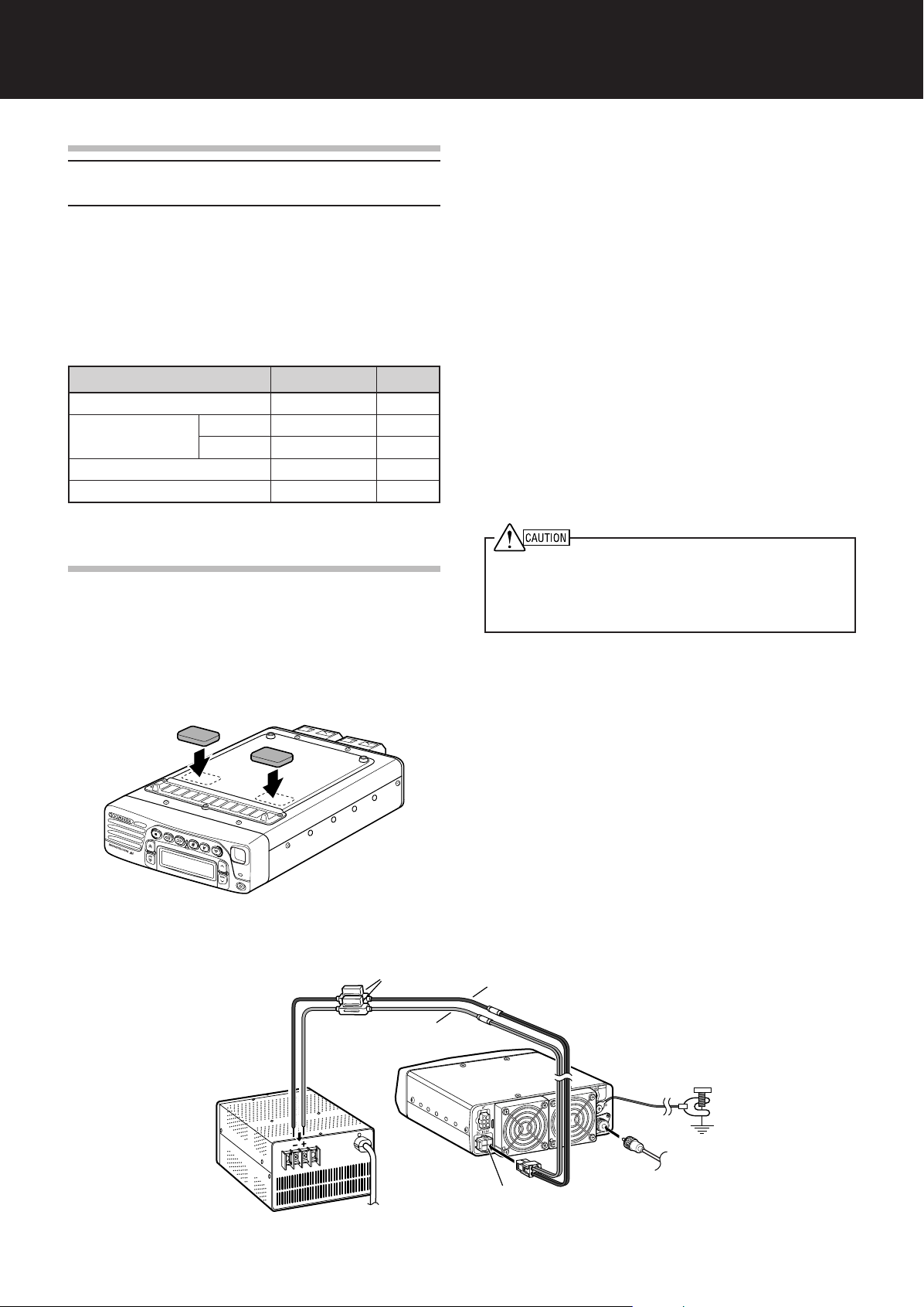
Earth ground
Black (—)
Red (+)
Fuse (25 A)
DC 13.6 V
DC Power supply
(20.5 A or more)
To antenna
UNPACKING AND CHECKING EQUIPMENT
Note: The following unpacking instructions are for use by your
KENWOOD dealer, an authorized KENWOOD service facility, or
the factory.
Carefully unpack the transceiver. We recommend
that you identify the items listed in the following table
before discarding the packing material. If any items
are missing or have been damaged during shipment,
file a claim with the carrier immediately.
SUPPLIED ACCESSORIES
BASE STATION INSTALLATION
FOOT PADS
A set of foot pads are provided so that you can
protect the surface of your desk/table/shelf from
scratching. Apply the foot pads to the base of the
transceiver.
ANTENNA CONNECTION
For best performance:
• Use a properly adjusted, good-quality 50 Ω
antenna.
• Use a good-quality 50 Ω coaxial cable and
connector.
• Match the impedance of the coaxial cable and
antenna so that the SWR is 1.5:1 or less.
• Ensure that all connections are clean and tight.
The transceiver’s protection circuit will activate if the
SWR is greater than 2.5:1, but do not rely on
protection to compensate for a poorly functioning
antenna system. High SWR will cause the transmit
output to drop, and may lead to radio frequency
interference with consumer products such as stereo
receivers and televisions. You may even interfere
with your own transceiver. Reports that your signal is
garbled or distorted, especially at peak modulation,
may indicate that your antenna system is not
transmitting efficiently.
◆ Transmitting without first connecting an antenna or other
matched load may damage the transceiver. Always connect
the antenna to the transceiver before transmitting.
◆ Use a lightning arrestor to prevent fire, electric shock, or
damage to the transceiver.
GROUND CONNECTION
•A good DC ground is required to prevent such
dangers as electric shock.
•A good RF ground is required for superior
communcations, against which the antenna
system can operate.
Both of these conditions can be met by providing a
good earth ground for your station. Bury one or more
ground rods or a large copper plate under the ground,
and connect this to the transceiver GND terminal.
Use heavy gauge wire or a copper strap, cut as short
as possible, for the connection. Ensure that all
connections are clean and tight.
Base Station Installation
1
Page 6
DC POWER SUPPLY CONNECTION
In order to use this transceiver as a base station, you
will need a separate 13.6 V DC power supply with a
current capacity of 20.5 A or higher (purchased
separately).
◆ Do not directly connect the transceiver to an AC outlet.
◆ Do not substitute the supplied DC power cable with a cable
with smaller gauge wires.
◆ Before connecting the DC power supply to the transceiver, be
sure to switch the DC power supply OFF.
◆ Do not plug the DC power supply into an AC outlet until you
make all connections.
1 Connect the supplied DC power cable to the
regulated DC power supply and check that the
polarities are correct (Red: positive, Black:
negative).
2 Connect the connectorized end of the DC power
cable to the DC 13.6 V powerconnector on the
rear of the transceiver.
• Press the DC power cable connector firmly into the
connector on the radiotelephone until the locking tab
clicks.
■ REPLACING FUSES
If the fuse blows, determine the cause then correct
the problem. After the problem is resolved, only
then replace the fuse. If newly installed fuses
continue to blow, disconnect the power plug and
contact your dealer for assistance.
Following are the ratings for fuses used with this
transceiver:
Transceiver: 4 A (for KAT-1 antenna tuner)
DC cable: 25 A
◆ When replacing any fuse, be sure to replace it with a fuse
of the same value. Never replace a fuse with a fuse that
has a higher value.
◆ Replace blown fuses only after investigating and
correcting the cause of the failed fuse.
MOBILE INSTALLATION
Various electronic equipment in your vehicle may malfunction if
they are not properly protected from the radio frequency energy
which is present while transmitting. Electronic fuel injection,
anti-skid braking, and cruise control systems are typical examples
of equipment that may malfunction. If your vehicle contains such
equipment, consult the dealer for the make of vehicle and enlist
his/her aid in determining if they will perform normally while
transmitting.
Note: The following preparation instructions are for use by your
KENWOOD dealer, an authorized KENWOOD service facility, or
the factory.
INSTALLING THE TRANSCEIVER
For passenger safety, install the transceiver securely using an
optional mounting bracket so the transceiver will not break loose
in the event of a collision.
1 Mark the position of the holes in the dash by using
the mounting bracket as a template. Drill the
holes, then attach the mounting bracket using
self-tapping screws supplied with the bracket.
• Be sure to mount the transceiver in a location where
the controls are within easy reach of the user and
where there is sufficient space at the rear of the
transceiver for cable connections.
2 Connect the antenna and the supplied power
cable to the transceiver {page 3}.
3 Slide the transceiver into the mounting bracket
and secure it.
4 Mount the microphone hanger in a location where
it will be within easy reach of the user.
• The microphone and microphone cable should be
mounted in a place where they will not interfere with
the safe operation of the vehicle.
ANTENNA CONNECTION
For best performance:
• Use a properly adjusted, good-quality 50 Ω
antenna.
• Use a good-quality 50 Ω coaxial cable and
connector.
Coupling the antenna to the transceiver via feed lines
having an impedance other than 50 Ω reduces the
efficiency of the antenna system and can cause
interference to nearby broadcast television receivers,
radio receivers, and other electronic equipment.
Transmitting without first connecting an antenna or other matched
load may damage the transceiver. Always connect the antenna to
the transceiver before transmitting.
2
Page 7
GROUND CONNECTION
a
•A high-quality ground installation significantly
improves the performance of a mobile antenna.
Securely connect a low-resistance ground strap (or
large gauge copper wire if unavailable) from the
transceiver GND terminal to the vehicle chassis.
Clean paint or dirt from the vehicle connection point
to expose bare metal before connecting the ground.
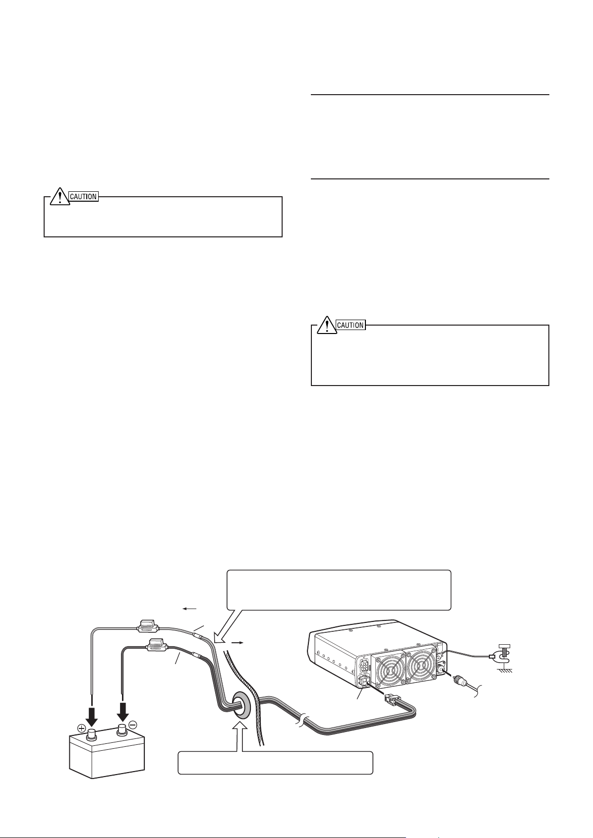
DC POWER CABLE CONNECTION
The transceiver operates in 12 V negative ground systems only!
Check the battery polarity and voltage of the vehicle before
installing the transceiver.
1 Check for an existing hole, conveniently located in
the firewall, where the power cable can be passed
through. If no hole exists, use a circle cutter to
drill the firewall, then install a rubber grommet.
2 Run the two power cable leads through the firewall
and into the engine compartment, from the
passenger compartment.
3 Connect the red lead to the positive (+) battery
terminal and the black lead to the negative (–)
battery terminal.
• Use the full length of the cable without cutting off any
excess; in particular, never remove the fuse holders.
•To prevent the risk of short circuits, disconnect other
wiring from the negative (–) battery terminal before
connecting the transceiver. Reconnect the wiring
after connecting the transceiver to the battery.
• Locate the fuse as close to the battery as possible.
4 Coil and secure the surplus cable with a retaining
band.
• Be sure to leave enough slack in the cables so the
transceiver can be removed for servicing while
keeping the power applied.
• Ensure that the cable is isolated from heat and
moisture. If necessary, wrap heat-resistant tape
around the fuse holder to protect it from moisture.
• If using a noise filter, it should be installed with an
insulator to prevent it from touching metal on the
vehicle.
5 Connect the DC power cable to the rear of the
transceiver.
• Press the connectors firmly together until the locking
tab clicks.
Note:
◆ We do not recommend using the cigarette lighter socket, as
some cigarette lighter sockets introduce an unacceptable
voltage drop.
◆ If you use the transceiver for a long period when the vehicle
battery is not fully charged or when the engine is OFF, the
battery may become discharged and will not have sufficient
reserves to start the vehicle. Avoid using the transceiver
under these conditions.
■ REPLACING FUSES
If the fuse blows, determine the cause then correct
the problem. After the problem is resolved, only
then replace the fuse. If newly installed fuses
continue to blow, disconnect the power plug and
contact your dealer for assistance.
Following are the ratings for fuses used with this
transceiver:
Transceiver: 4 A (for KAT-1 antenna tuner)
DC cable: 25 A
◆ When replacing any fuse, be sure to replace it with a fuse
of the same value. Never replace a fuse with a fuse that
has a higher value.
◆ Replace blown fuses only after investigating and
correcting the cause of the failed fuse.
Engine compartment
Black (–)
12 V battery
Place the DC cable securely within the wall of the engine
compartment. Ensure that the cable does not come into
contact with excessive heat, vapor, and/or water.
Red (+)
Passenger
compartment
DC 13.6V
Use a rubber or plastic grommet so that the cable
does not directly touch the vehicle chassis.
Mobile Installation
Vehicle
chassis
To antenn
3
Page 8
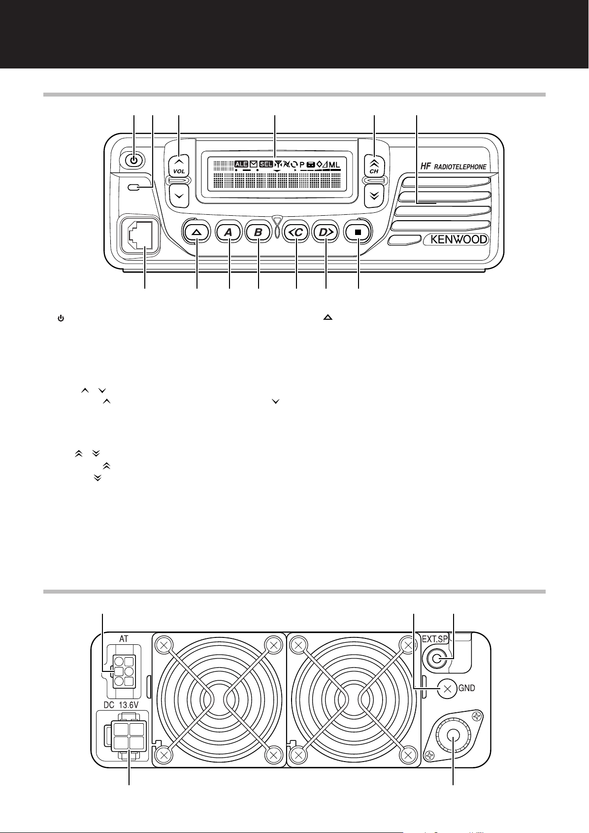
GETTING ACQUAINTED
q
u i o !0!0 !1!1 !2!2 !3!3
w e r t y
q
r t
w e
FRONT PANEL
qq
q (Power) switch
qq
Press to switch the transceiver power ON. Press
again to switch the power OFF.
ww
w Transmit/ Busy/ Call indicator
ww
Lights red while transmitting and green while
receiving a signal. Flashes orange during selcall.
ee
e VOL / keys
ee
Press the key to increase the volume and the
key to decrease the volume.
rr
r Display
rr
Refer to page 5.
tt
t CH / keys
tt
Press the key to increase the channel number
and the key to decrease the channel number.
yy
y Internal Speaker
yy
Audio is heard from this speaker if no external
speaker is connected.
uu
u Microphone jack
uu
Connect an optional microphone to this jack.
ii
i key
ii
Press to activate its programmable function
{page 7}. The default setting is Antenna Tuner.
oo
o A key
oo
Press to activate its programmable function
{page 7}. The default setting is Squelch Level.
!0!0
!0 B key
!0!0
Press to activate its programmable function
{page 7}. The default setting is Scan.
!1!1
!1 <C key
!1!1
Press to activate its programmable function
{page 7}. The default setting is Clarifier.
!2!2
!2 D> key
!2!2
Press to activate its programmable function
{page 7}. The default setting is Mode.
!3!3
!3 ■ key
!3!3
Press to activate its programmable function
{page 7}. The default setting is Menu.
REAR PANEL
4
Page 9

qq
rotacidnI noitpircseD
lennahcmargorpnacrelaedruoY.seicneuqerfdnasemanlennahcehtsyalpsiD
sutatsdeviecersyalpsidoslA.seicneuqerffoecalpni,sretcarahc21otpuhtiwseman
.segassem
.edomuneMnielihwrebmununemehtsyalpsidoslA.srebmunlennahcehtsyalpsiD
.detavitcasinoitcnufELAlanoitpoehtnehwsraeppA
kcatsehtniderotssiegassemanehwsthgiL.egassemaevieceruoynehwsehsalF
.}51egap{yromem
.}31egap{detavitcaneebsahllacleSnehwsraeppA
sihctamdooganehwsthgiL.gninutsirenutannetnalanoitpoehtelihwsehsalF
.}81egap{metsysannetnaehthtiwdeniatbo
.}91egap{detavitcasinoitcnufreknalBesioNehtnehwsraeppA
.}21egap{edomnacSgnisuerauoynehwsraeppA
.}21egap{derreferPsademmargorpsilennahcdetcelesehtnehwsraeppA
sinocisihT.yromemreviecsnartruoyniderotsneebsahgnidroceranehwsraeppA
.}12egap{1-SGVlanoitpoehthtiwdesuylno
.}71egap{detavitcasinoitcnufrelbmarcSehtnehwsraeppA
.}81egap{detavitcasinoitcnufreifiralCehtnehwsraeppA
.}9egap{rewopmuidemgnisugnittimsnartnehwsraeppA
.}9egap{rewopwol-muidemgnisugnittimsnartnehwsraeppA
.}9egap{rewopwolgnisugnittimsnartnehwsraeppA
.}91egap{detavitcaneebsahnoitcnufXUAehtnehwsraeppA
.}71egap{detavitcaneebsahnoitcnufXOVehtnehwsraeppA
.reviecsnartsihtnodesutonsinocisihT
.}21egap{ecneuqesgninnacsehtotdeddasilennahcdetcelesehtnehwsraeppA
.}91egap{detavitcaneebsahnoitcnufreifilpma-erPehtnehwsraeppA
asasevres,gnittimsnartelihW.htgnertslangisdeviecerehtsyalpsid,gniviecerelihW
noitacidnielacs-llufa,retemFRnasagnitcaelihW.retemFRtimsnartevitaler
.rewopmumixamdemmargorpehtotsdnopserroc
q AT connector
qq
Attach an optional KAT-1 external Antenna Tuner
here.
ww
w GND terminal
ww
Connect a heavy gauge wire or copper strap
between this ground terminal and the nearest
earth ground.
ee
e EXT SP jack
ee
Connect an external 4 ~ 8 Ω speaker to this jack.
Mates with a 3.5 mm (1/8") diameter, 2-conductor
(mono) plug. Connecting an external speaker
automatically cuts off the audio from the internal
speaker.
DISPLAY
rr
r DC 13.6 V power input connector
rr
Connect a 13.6 V DC power source to this
connector. Use the supplied cable with a
regulated DC power supply.
tt
t Antenna connector
tt
Connect the feed line from your 50 Ω antenna to
this connector. Mates with a PL-259 male
connector.
5
Page 10

MICROPHONE (OPTIONAL)
q
q
w
q
q
w
Optional KMC-30 Microphone
qq
q PTT (Push-to-Talk) switch
qq
Press and hold this switch, then speak into the
microphone to make a call.
ww
w Keypad
ww
Press these keys to enter a frequency {page 8}.
Press the key to cancel the frequency entry and
the # key to complete the frequency entry.
Press the A, B, C, D, #, and keys to activate
their programmable functions {page 7}.
In Selcall Mode, press these keys to enter a
Selcall/Status ID {page 13}. Press the key to
unmute the speaker in Selcall mode and the # key
to reset the entered Selcall ID. Use the A, B, C,
and D keys to access memory codes.
Optional KMC-32 Microphone
Optional KMC-35 Microphone
Optional KMC-36 Microphone
6
Page 11

PROGRAMMABLE FUNCTIONS
The , S, A, <B, C>, ■, and optional microphone A,
B, C, and D keys can be programmed with the
functions listed below. The microphone # and keys
can be programmed only with the Channel Up/Down
and Volume Up/Down functions. Please contact your
dealer for further details on these functions.
• Antenna Tuner
• Anti-VOX Gain
• Auto Recording
• AUX
• Call Type
• Channel Down
• Channel Up
• Clarifier
• Direct Call 1 ~ 4
• Direct CH 1 ~ 4
• Direct Status Call 1 ~ 4
• Display Character
• Emergency
• LCD Brightness
• Menu
• Mode
• Monitor
• Noise Blanker
• None
• Playback 1 ~ 4
• Pre-amplifier/ Attenuator
• Scan
• Scan Delete/Add
•Scrambler
• Selcall
• Squelch Level
•Transmit Power
• VFO
•Volume Down
•Volume Up
• VOX
• VOX Delay
• VOX Gain
1
“Auto Recording” and “Playback 1 ~ 4” can be programmed only
when the optional VGS-1 board has been installed.
2
“Emergency” can be programmed only on the key.
1
2
1
7
Page 12

BASIC OPERATIONS
USB
DATA
LSB
FSK
CW
AM
SWITCHING POWER ON/ OFF
Press and hold the switch to switch the transceiver
ON.
•A beep sounds and the power-on message
momentarily appears.
Press and hold the switch again to switch the
transceiver OFF.
ADJUSTING THE VOLUME
Press the VOL key to increase the volume and the
VOL key to decrease the volume.
• Additionally, you can press and hold the VOL /
keys to continuously change the volume level,
rather than adjusting it by only 1 step at a time.
SELECTING A CHANNEL
Press the CH key to increase the channel number
and the CH key to decrease the channel number.
• Additionally, you can press and hold the CH /
keys to continuously change the channel number,
rather than changing it by only 1 step at a time.
2 Enter your desired frequency using a microphone
keypad (0 ~ 9).
• Direct entry only allows you to enter down to the 10’s
value; 0 is automatically selected for the 1’s value.
3 After entering a frequency using the microphone
keypad, press the # key.
•To cancel the frequency entry, press the key; the
frequency will return to the original frequency before
you started to enter your new frequency.
4 To exit VFO mode and return to your
preprogrammed memory channels, press and hold
the VFO key again.
■ VFO S
TEP VALUE
When using the CH / keys to select a
frequency in VFO mode, the frequency is adjusted
by a pre-determined step value. You can adjust
this step value as follows:
1 Press the key programmed as VFO.
2 Press the <C and D> keys to select the desired
digit (10’s, 100’s, 1000’s, etc.).
3 Press the CH / keys to select the desired
value for the digit you selected in the previous
step.
• The default step value is 10 Hz.
4 Press the key to store the new step value
and exit the VFO step value adjustment.
SELECTING A MODE
DIRECT FREQUENCY ENTRY
Besides using the CH / keys to select your
pre-programmed memory channels, you can directly
enter a VFO station frequency using an optional
microphone keypad.
1 Press and hold the key programmed as VFO for
approximately 1 second.
• The frequency of the currently selected channel
appears on the display along with the selected
operating mode.
The mode stored with each channel can be
temporarily changed. To change the operating mode:
1 Press the key programmed as Mode.
2 Continuously press the Mode key to cycle through
the various available operation modes as
displayed below:
3 After selecting your desired mode, perform no
operations for 1 second to return to save the
operation mode and exit.
DATA OPERATION
Your dealer can program various settings for FSK and
DATA modes. Ask your dealer for details.
8
Page 13

TRANSMITTING
High Medium Medium-Low Low
CHANGING THE TRANSMIT POWER
Note: You cannot transmit on channels that have only a receive
frequency stored.
1 Select the desired channel or frequency.
2 Press microphone PTT switch and speak into the
microphone. Release the PTT switch to receive.
• For best sound quality at the receiving station, hold
the microphone approximately 3 ~ 4 cm (1.5 inches)
from your mouth.
VOX (VOICE-OPERATED TRANSMISSION)
VOX eliminates the need of manually switching to
transmit mode each time you want to make a call.
The transceiver automatically switches to transmit
when the VOX feature senses that you have begun
speaking into the microphone.
• When VOX is activated, the VOX icon
(
) appears on the display.
To properly use the VOX feature, you must properly
set up the VOX Gain, VOX Anti-Gain, and VOX Delay
Time for your environment {page 17}.
CW KEYING
1 Select a CW channel.
2 With a CW key connected to the transceiver, begin
transmitting by keying.
• In order to use CW keying, your dealer must have
enabled the CW break-in function on your
transceiver. The default setting for CW break-in is
disabled.
• When CW break-in is enabled, pressing the PTT
switch will not allow transmission. When CW
break-in is disabled, pressing the PTT switch will
allow transmission.
3 To end the transmission, stop keying.
• After keying has stopped, the transceiver will remain
in transmit mode momentarily before returning to
receive mode.
If your call is too weak (or is using unnecessarily high
power), you can adjust the transmit power for your
channel/frequency.
1 Press the key programmed as Transmit Power.
2 Continuously press the Transmit Power key to
cycle through the various power settings as
displayed below:
•Your dealer may have set a power limit on some
channels. In this case, the settings available may be
limited. Additionally, if a channel is set up as
receive-only, you will be unable to set a transmit
power for that channel.
• When using Low power, “L” appears on the display.
When using Medium-Low power, “ML” appears on
the display. When using Medium power, “M” appears
on the display. When using High power, no icon
appears on the display.
TIME-OUT TIMER
If you continuously transmit for a period of time that
exceeds the programmed time set by your dealer (default
is OFF), the transceiver will stop transmitting and an alert
tone will sound. To stop the tone, return the transceiver to
receive mode.
Your dealer can program the TOT time in the range of 3 to
30 minutes.
OVERHEATING
The internal fan operates automatically to keep the
transceiver cool, especially during extended
transmissions and extended operation using high
power. However, if the temperature rises too high, an
internal protection circuit will activate, reducing the
transceiver power.
• “HIGH–TEMP” appears on the display.
Note: When “HIGH–TEMP” appears on the display, ensure that
the transceiver cooling fan is functioning.
9
Page 14

SQUELCH/ MONITOR
The purpose of squelch is to silence audio output
from the speaker when no signals are present.
Setting the squelch threshold too high causes the
squelch to remain closed while a weak signal is
present. Setting the threshold too low allows noise to
be heard between transmissions from other stations.
SQUELCH LEVEL
Adjust the squelch level to just eliminate the
background noise when no signal is present. If
signals are weak, set the control to a lower threshold:
1 Press the key programmed as Squelch Level.
2 Press the <C key to decrease the squelch level
(open) and the D> key to increase the squelch
level (tighten).
3 Press the
and exit the squelch level adjustment.
key to store the new squelch level
CHANNEL MONITORING
You can use the key programmed as Monitor to
listen to weak signals that you cannot hear during
normal operation and to adjust the volume when no
signals are present on your selected channel.
Press and hold the Monitor key to turn the
transceiver squelch off.
Release the Monitor key to return to normal
operation.
10
Page 15

MENU SETUP
uneM
.oN
emaNuneM emaNnoitcnuFlluF
1LVLLQStnemtsujdaleveLhcleuqS
2IRALCreifiralC
3BNreknalBesioN
4THGIRBssenthgirBDCL
5PSID
:yalpsiD
ycneuqerfroemanlennahc
6XOVFFO/NOXOV
7YLDXOVemiTyaleDXOV
8NIAGXOVniaGXOV
9XOVITNAniaGXOV-itnA
01PYTLLACepyTllaC
uneM
.oN
emaNuneM yeKsseccAtceriD
1LVLLQSleveLhcleuqS
2IRALCreifiralC
3BNreknalBesioN
4THGIRBssenthgirBDCL
5PSIDyalpsiD
6XOVXOV
7YLDXOVyaleDXOV
8NIAGXOVniaGXOV
9XOVITNAniaGXOV-itnA
01PYTLLACepyTllaC
Many functions of this transceiver are selected or
configured via a software-controlled Menu rather than
using physical controls on the transceiver. Once
familiar with the Menu system, you will appreciate the
versatility it offers.
ACCESSING THE MENU
The following procedure explains how to check or
change any of the Menu items:
1 Press the key programmed as Menu.
• Alternatively, you can press any key that has been
pre-programmed with direct access to a particular
menu. For example, to access Menu No. 1, you
could press the key programmed as Squelch Level.
2 Press the CH / keys to select the desired
Menu number.
• CH increments the Menu number and CH
decrements the Menu number.
MENU CONFIGURATION
Following is a list of “Direct Access” keys that can be
programmed for each of the Menus.
3 Press the <C and D> keys to select a parameter.
• Alternatively, you can press the KMC-32 microphone
C and D keys.
4 Press the key to save your selection and exit
Menu mode.
• Alternatively, you can press the microphone key.
11
Page 16

SCAN
Scan allows each of the channels that has a receive
frequency stored to be automatically monitored for
activity. Channels must be added to the scanning
sequence in order to be scanned.
To activate Scan, press the key programmed as
Scan.
• The icon appears on the display.
• The channel add indicator (
on the display when the selected channel is added to
the scan sequence.
• If only one channel is added to the scan sequence or
has a frequency stored, pressing the Scan key causes
an error tone to sound and Scan does not operate.
To stop scanning, press the Scan key again.
) will appear
BUSY FREQUENCY STOP
The transceiver will automatically pause on a channel
when a signal is detected. The transceiver will
remain on the busy channel for either a short time or
until the signal drops out, depending on which Scan
Resume type your dealer has set up (see below).
• The squelch must be adjusted to the noise threshold
point with no signals present for Busy Frequency Stop to
operate.
When the transceiver has paused on a channel, you
can transmit by pressing the microphone PTT switch.
Depending on your dealer settings, Scan may either
end when you transmit or continue to operate. If
Scan is set to continue even after transmitting, then it
will remain on the current channel for a
predetermined time before continuing. This time is
set so that if a signal re-appears on the channel, or if
you transmit again, Scan will remain on the current
channel until the signal either drops out or you stop
transmitting.
SCAN RESUME TYPE
Scan Resume controls when the transceiver
continues scanning after stopping due on a busy
channel.
• Time-Operated Scan: After stopping on a busy
channel, Scan resumes after a predetermined
time (set by your dealer) whether or not the signal
is still present on the channel.
• Carrier-Operated Scan: The transceiver remains
on the busy channel until the signal ends. Scan
resumes after a predetermined time (set by your
dealer) after the signal has dropped out.
PREFERRED SCAN
A Preferred channel must be programmed in order for
Preferred Scan to function.
During Scan, the Preferred channel is checked during
regular intervals (set up by your dealer). This interval
ensures that you do not miss important transmissions
on your Preferred channel, while scanning other
channels.
• The indicator appears on the display when the
Preferred channel is selected.
ADD TO SCAN/ REMOVE FROM SCAN
Press the key programmed as Scan Delete/Add, to
add or remove each channel to or from the scan
sequence. Only those channels that have been
added to the scan sequence will be scanned.
Deleted channels will be skipped.
• The channel add indicator ( ) will appear
on the display when the selected channel is added to
the scan sequence.
SCAN REVERT CHANNEL
Your dealer can set up 1 of 4 different types of Scan
Reverts for your transceiver. A Scan Revert channel
is the channel that you are able to transmit on during
Scan, when you press the microphone PTT switch.
• Preferred Channel: If your dealer has
programmed a Preferred channel, this channel is
the revert channel.
• Preferred Channel + Talkback: If your dealer
has programmed a Preferred channel, this
channel is the revert channel. However, when
paused on a busy channel, you are able to “talk
back” on that channel until Scan resumes.
• Selected Channel: The last channel selected
before you begain scanning is assigned as the
revert channel.
• Selected Channel + Talkback: The last channel
selected before you begain scanning is assigned
as the revert channel. However, when paused on
a busy channel, you are able to “talk back” on that
channel until Scan resumes.
12
Page 17

SELECTIVE CALLS
A Selective Call, or Selcall, is a voice call to a
particular station or group of stations.
ACTIVATING SELCALL MODE
To activate Selcall Mode, access Menu No. 10 (Call
Type) {page 11} and set the call type to Selcall.
MANUAL SELCALLS
If your dealer has programmed your transceiver with
a list of stations, you can manually select a station to
send a selcall.
SELECTING A STATION USING THE TRANSCEIVER KEYS
1 While in Selcall Mode, press the key programmed
as Selcall to view the Selcall list.
2 Press the CH and keys to select the ID of the
station you want to call.
3 Press the PTT switch and begin your conversation.
• Alternatively, you can press the ■ key to page the
selected station, rather than making a voice call.
• While making the call, the icon flashes.
4 When the call connects, the LED indicator flashes
orange. Begin your conversation by pressing the
PTT switch and speaking into the microphone.
5 After you have finished your call, release the PTT
switch.
•A proceed tone sounds and the icon remains on
the display.
• Depending on the Auto Reset time set up by your
dealer, your speaker will mute if no response is
received. You can unmute the speaker to remain in
standby mode by pressing the key programmed as
Monitor.
3 After you have finished your call, release the PTT
switch.
•A proceed tone sounds and the icon remains on
the display.
• Depending on the Auto Reset time set up by your
dealer, your speaker will mute if no reponse is
received. You can unmute the speaker to remain in
standby mode by pressing the # key or the key
programmed as Monitor.
DIRECT SELCALLS
Your dealer can program up to 4 special keys so that
you can quickly and easily make a selcall to a specific
station.
Press the key programmed as Direct Call 1 to
Direct Call 4 to send a selcall to the stations
programmed onto those keys.
• While making the call, the icon flashes. When the
call is complete, the
• Depending on the Auto Reset time set up by your dealer,
your speaker will mute if no reponse is received. You
can unmute the speaker to remain in standby mode by
pressing the # key or the key programmed as Monitor.
icon remains on the display.
RECEIVING A SELCALL
When a Selcall is received, an alert tone will sound
and the calling station’s ID (or name) will appear on
the display.
To respond to the call, press the PTT switch and
speak into the microphone.
• Depending on the Auto Reset time set up by your dealer,
your speaker will mute if no reponse is received. You
can unmute the speaker to remain in standby mode by
pressing the # key or the key programmed as Monitor.
MEMORY CALLS
If a character message has been set up in one of the
4 available memory call locations, you can easily
send those messages when making a Selcall.
SELECTING A STATION USING A MICROPHONE KEYPAD
1 While in Selcall Mode, press and hold the PTT
switch, then enter the 3-digit ID of the station you
want to call, followed by the # key.
• Releasing the PTT switch before entering the # key
will cancel the call.
• The key is used as a wild card when entering
group codes. For example, sending the group code
00 allows you to contact all stations that have “00”
as the last 2 digits of their ID codes.
• While making the call, the icon flashes.
2 When the call connects, the LED indicator flashes
orange. Begin your conversation by pressing the
PTT switch and speaking into the microphone.
SELECTING A MEMORY CALL USING THE TRANSCEIVER KEYS
1 While in Selcall Mode, press the key programmed
as Selcall to view the Selcall list.
13
Page 18

2 Press the CH and keys to select CODE A to
CODE D.
• Press the D> key to view the character message of
the selected code, and the <C key to return to the
code selection.
MANUAL STATUS CALLS
You can send and receive 2-digit Status codes which
may be decided in your talk group. Codes can
contain up to 12 alphanumeric character messages.
Status codes range from 10 to 99 (80 ~ 99 are
reserved for special messages).
3 Press the ■ key or the PTT switch to send the
message.
• While making the call, the icon flashes.
4 When the call connects, the LED indicator flashes
orange. Begin your conversation by pressing the
PTT switch and speaking into the microphone.
•A proceed tone sounds and the icon remains on
the display.
5 After you have finished your call, release the PTT
switch.
• Depending on the Auto Reset time set up by your
dealer, your speaker will mute if no reponse is
received. You can unmute the speaker to remain in
standby mode by pressing the key programmed as
Monitor.
SELECTING A MEMORY CALL USING A MICROPHONE KEYPAD
1 While in Selcall Mode, press and hold the PTT
switch, then enter the # key, key A to D (to select
the respective memory location), followed by the #
key again
• Releasing the PTT switch before entering the final #
key will cancel the call.
• While making the call, the
2 When the call connects, the LED indicator flashes
orange. Begin your conversation by pressing the
PTT switch and speaking into the microphone.
•A proceed tone sounds and the icon remains on
the display.
3 After you have finished your call, release the PTT
switch.
• Depending on the Auto Reset time set up by your
dealer, your speaker will mute if no reponse is
received. You can unmute the speaker to remain in
standby mode by pressing the # key or the key
programmed as Monitor.
icon flashes.
MAKING A STATUS CALL USING THE TRANSCEIVER KEYS
1 While in Selcall Mode, press the key programmed
as Selcall to view the Selcall list.
2 Press the CH and keys to select the ID of the
station you want to call.
3 Press the D> key to view the Status list.
4 Press the CH and keys to select the status
you want to transmit.
5 Press the ■ key or the PTT switch to send the
status call.
• While making the call, the icon flashes and
“SEND DATA” appears on the display.
• “COMPLETE” appears on the display when the call
has been successfully transmitted.
• If the call cannot go through, “NO REPLY” appears
on the display.
MAKING A STATUS CALL USING A MICROPHONE KEYPAD
1 While in Selcall Mode, press and hold the PTT
switch, then enter the 3-digit ID of the station you
want to call.
2 While continuing to hold the PTT switch, press the
key to enter Status entry mode.
3 While continuing to hold the PTT switch, enter the
2-digit ID number of the status you want to
transmit.
4 While continuing to hold the PTT switch, press the
# key to send the status call.
• Releasing the PTT switch before entering the # key
will cancel the call.
• While making the call, the icon flashes and
“SEND DATA” appears on the display.
• “COMPLETE” appears on the display when the call
has been successfully transmitted.
• If the call cannot go through, “NO REPLY” appears
on the display.
14
Page 19

DIRECT STATUS CALLS
Your dealer can program up to 4 special keys so that
you can quickly and easily make a status call to a
specific station.
Press the key programmed as Direct Status Call 1 to
Direct Status Call 4 to send the programmed status
call to the stations programmed onto those keys.
• While making the call, the icon flashes and “SEND
DATA” appears on the display. When the call is
complete, the
• “COMPLETE” appears on the display when the call has
been successfully transmitted.
• If the call cannot go through, “NO REPLY” appears
on the display.
icon remains on the display.
OPTIONAL VOICE MESSAGES
If both you and the target transceiver have optional
VGS-1 units installed on your transceivers {page 20},
you can also use voice recordings as status
messages.
1 While in Selcall Mode, press the key programmed
as Selcall to view the Selcall list.
RECEIVING A STATUS CALL
A maximum of 5 received messages can be stored in
the stack memory of your transceiver. These saved
messages can be reviewed after reception. When
the stack memory is full, either the oldest message
will be erased when a new message is received or
the new message will not be stored in the stack
memory.
1 The icon will flash and a calling ID will appear
when a status call is received.
2 Press the D> key to view the status call.
3 Press the key to return to normal operation.
• The icon remains on the display when a message
is stored in the stack memory.
2 Press the CH and keys to select the ID of the
station you want to call.
3 Press the D> key to view the Status list.
4 Press the CH and keys to select “VOICE
REC”.
5 Press the ■ key or the PTT switch to initiate the
call.
• While making the call, the icon flashes.
•A timer appears on the display when the transceiver
is ready to receive your recording.
6 Press the PTT switch and speak into the
microphone to begin your recorded message.
• As you make your recording, the timer will count
down.
7 Press the key to end the recording at any time
before the timer expires.
REVIEWING MESSAGES IN THE STACK MEMORY
1 Press and hold the key programmed as Selcall for
1 second to enter Status Confirmation mode.
• The name or ID of the person who sent the last
received message is displayed with the message
number.
• The icon will flash when there is a message
stored in memory that has not yet been viewed.
• The icon will flash when there is a voice message
stored in memory.
2 Press the CH and keys to select the desired
caller ID.
3 Press the D> key to view the message and the <C
key to return to the caller ID list.
• When selecting a voice message, “VOICE MSG”
appears on the display and the message will be
played back.
4 Press the key to return to normal operation.
•To delete the selected message, press the A key. To
confirm the deletion, press the ■ key. To cancel,
press the key.
•To delete all messages, press and hold the A key for
1 second. To confirm the deletion, press the ■ key.
To cancel, press the
key.
15
Page 20

SEND THE GPS DATA
If a GPS unit has been installed and is set up by your
dealer, your transceiver may automatically transmit
your GPS data.
MANUALLY SENDING THE GPS DATA
1 While in Selcall Mode, press the key programmed
as Selcall to view the Selcall list.
2 Press the CH and keys to select the ID of the
station you want to call.
3 Press the D> key to view the Status list.
4 Press the CH and keys to select “GPS
DATA”.
5 Press the ■ key or the PTT switch to send the
GPS data.
• While making the call, the icon flashes and
“SEND DATA” appears on the display.
• “COMPLETE” appears on the display when the call
has been successfully transmitted.
GPS POLLING
If your transceiver receives a GPS Polling request, it
will automatically transmit your GPS data to the
requesting station.
• “SEND DATA” appears on the display until the data has
been transmitted.
SHORT TEXT MESSAGES
To send and receive short text messages, you must
connect the transceiver to a PC. Ask your dealer for
details.
• Short text messages can contain a maximum of 48
characters.
16
Page 21

ADVANCED OPERATIONS
DIRECT CHANNEL
Your dealer can program up to 4 keys to allow you to
quickly and easily jump to a frequently used channel.
Press the keys programmed as Direct CH 1 to Direct
CH 4 to select the memory channels they have been
programmed to access.
SCRAMBLER
If your dealer has installed an optional scrambler
board, you can make private calls to others. Although
the scrambler function does not offer complete
privacy with your calls, it does prevent others from
easily listening in on your calls. When activated, the
transceiver distorts your voice so that anybody
listening to your conversation will be unable to clearly
hear what you are saying.
In order for members of your own group to clearly
hear your call while you are using the scrambler, all
other members must have the same scrambler code
set up on their transceivers. This distorts everybody’s
voice while transmitting and corrects the voice
message on your own transceiver when you receive
the call.
To activate the scrambler, press the key programmed
as Scrambler.
• The icon appears on the display while the scrambler
is active.
VOX (VOICE-OPERATED TRANSMIT) SETUP
VOX eliminates the need of manually switching to
transmit mode each time you want to make a call.
The transceiver automatically switches to transmit
when the VOX feature senses that you have begun
speaking into the microphone.
You can switch the VOX feature ON and OFF by
pressing the key programmed as VOX or by
accessing Menu No. 6 {page 11}.
• When VOX is activated, the VOX icon
(
To properly use the VOX feature, you must properly
set up the VOX Gain, Anti-VOX Gain, and VOX Delay
Time for your environment {see below}.
VOX GAIN
This setting allows the transceiver to recognize sound
levels. If the VOX Gain is too low, the microphone
will not pick up your voice when you begin speaking.
Be sure to adjust the VOX Gain level to an
appropriate sensitivity to allow smooth transmission.
Sensitivity levels range from 1 to 9.
You can set the VOX Gain by pressing the key
programmed as VOX Gain or by accessing Menu
No. 8 {page 11}.
) appears on the display.
To deactivate the scrambler, press the Scrambler
key again.
CHANGING THE SCRAMBLER CODE
It is possible to change the pre-set scrambler code on
a channel:
1 Press and hold the key programmed as
Scrambler for approximately 1 second.
2 Press the <C or D> key to select a new code (from
1 to 16).
3 Press the key to store the new code and exit.
Note: If the scrambler memory is not enabled by your dealer,
changing the channel or turning the transceiver power OFF will
reset your scrambler code to the default setting.
ANTI-VOX GAIN
VOX operation is sometimes difficult when using high
speaker volumes. Adjust this control to reduce the
tendency of the transceiver to switch into transmit
mode due to the speaker output. Use the minimum
Anti-Gain level to achieve reliable VOX operation.
Anti-Gain levels range from 0 to 9.
You can set the Anti-VOX Gain by pressing the key
programmed as Anti-VOX Gain or by accessing
Menu No. 9 {page 11}.
17
Page 22

VOX DELAY TIME
EMERGENCY
Set this duration to change the amount of time that
the transceiver remains in transmit mode after you
stop speaking. Set the duration long enough so that
it does not cut off the end of your call. Delay times
range from 200 milliseconds to 3000 milliseconds
(3 seconds), in steps of 200 milliseconds. You can
also set the VOX Delay Time to OFF.
You can set the VOX Delay Time by pressing the key
programmed as VOX Delay or by accessing Menu
No. 7 {page 11}.
ANTENNA TUNER
In order to use the Antenna Tuner function, you must
first attach an optional external KAT-1 antenna tuner
to your transceiver.
1 Press and hold the key programmed as Antenna
Tuner for approximately 1 second to start tuning.
• The transmit indicator lights red and the icon
appears on the display and blinks.
•To cancel the tuning, press the Antenna Tuner key
at any time.
If your transceiver has been programmed with the
Emergency function, you can make emergency calls.
Your dealer can set up the transceiver Emergency
function to be accessed via voice, CW, or selcall.
Refer to the appropriate section below, depending on
how your transceiver has been set up.
Note: The Emergency feature can be set up onto a foot switch,
attached to the AUX terminal, for vehicle use.
1 Press and hold the key programmed as
Emergency.
• Depending on the delay time programmed into your
transceiver, the length of time you must hold the
Emergency key will vary.
• When the transceiver enters Emergency mode, the
transceiver will change to the Emergency channel
and begin transmitting based on how the transceiver
is set up by your dealer. Transmit periods are also
set by your dealer.
• Depending on your transceiver settings, the display
may either remain unchanged when you enter
Emergency mode, or a new display with a
preprogrammed text message will appear.
2 To exit Emergency mode, press and hold the
Emergency key again.
• If the Emergency mode completes the preset
number of cycles, Emergency mode will
automatically end and the transceiver will return to
the channel that was in use before Emergency mode
was entered.
2 Within 20 seconds, tuning will complete.
•A tone sounds, the transmit indicator turns off, and
• If tuning does not complete within 20 seconds, the
icon stops blinking and remains on the
the
display.
tuning action will stop, an error tone will sound, and
the antenna will not be tuned to the selected
channel.
If set up by your dealer, each time you press the PTT
switch to transmit, the tuning process will begin if the
antenna has not been tuned to the selected channel.
•To cancel the tuning process, press the Antenna Tuner
key at any time.
Note:
◆ Your dealer can set a beginning of transmit and end of
transmit tone for the transceiver.
◆ Your dealer can set the transceiver to emit tones and received
signals as normal or mute the speaker during Emergency
operation.
CLARIFIER
The Clarifier control changes the receive frequency,
without affecting the transmit frequency, by up to
±400 Hz.
You can set the Clarifier by pressing the key
programmed as Clarifier or by accessing Menu
No. 2 {page 11}.
• The Clarifier value can be set between –400 Hz and
+400 Hz in steps of 10 Hz.
• The icon appears on the display while the Clarifier is
set to a value other than 0 Hz.
18
Page 23

Pre-amp On Pre-amp/ ATT Off ATT On
NOISE BLANKER
PRE-AMPLIFIER/ ATTENUATOR
The Noise Blanker is effective in reducing or
eliminating ignition and/or pulse-type noises.
You can turn the Noise Blanker ON or OFF by
pressing the key programmed as Noise Blanker or
by accessing Menu No. 3 {page 11}.
• The icon appears on the display while the Noise
Blanker is ON.
LCD BRIGHTNESS
You can set the brightness of the display backlight
and the key illumination by pressing the key
programmed as LCD Brightness or by accessing
Menu No. 4 {page 11}.
• The brightness levels can be set as High, Low, and Off.
• The key illumination can be set only as on or off.
The pre-amplifier allows you to boost the power of the
received signal, and the attenuator attempts to cut
out any interfering signals you may be receiving.
You can turn the pre-amplifier/ attenuator on or off
using the key programmed as Pre-amplifier/
Attenuator. Depending on how each channel has
been set up by your dealer, pressing the
Pre-amplifier/ Attenuator key will cycle to the next
setting, as displayed below.
• When the pre-amplifier is ON, the pre-amp icon
(
pre-amp/ ATT is OFF or when ATT is ON, the icon does
not appear on the display.)
• Changing the channel or frequency reverts the setting
back to the programmed setting.
) appears on the display. (When the
POWER-ON TEXT
Your dealer may have programmed your transceiver
to display a text message when the transceiver is
turned on. This message will appear on the display
momentarily before reverting to your regular channel/
frequency operation display.
DISPLAY NAME/ FREQUENCY
You can select whether you want to show a channel
name or the frequency of that channel on your
transceiver display. You can change the display
settings by pressing the key programmed as Display
Character or by accessing Menu No. 5 {page 11}.
• If your dealer has not set up a name for a particular
channel, the channel number will appear instead.
AUXILIARY
If a key has been programmed with the AUX function,
you can press that key to turn the Auxiliary Port on
and off. Ask your dealer for details.
• When the Auxiliary Port is activated, the AUX indicator
(
) appears on the display.
19
Page 24

VGS-1 OPTIONAL VOICE GUIDE & STORAGE UNIT
When using the optional VGS-1 voice guide &
storage unit, you gain access to the transceiver’s
voice recorder and voice announcement functions.
Ask your dealer for details.
VOICE MEMOS
RECORDING A VOICE MEMO
You can record up to 4 voice memos, each with a
duration of up to 15 seconds. To record a voice
memo for later playback:
1 Press and hold the key programmed as
Playback 1 to 4 for approximately 1 second to
begin recording. (Each Playback key corresponds
to a memory location of 1 to 4.)
• The duration of recording memory will appear on the
display and begin counting down. The voice memo
can record only the received signal.
Note: Playback keys can be set up for either voice memos or
voice messages by your dealer. The keys function differently
depending on how they are set up, so be sure to press a
Playback key set up for use for voice memos.
2 Press the key to end the recording at any time
and store it into the transceiver memory.
• If the memory becomes full, recording will stop
automatically and store the voice memo to memory.
• “WRITING” appears on the display while the
recording is being stored to memory.
DELETING A VOICE MEMO
To delete a recorded voice memo:
1 Press the key programmed as Playback 1 to 4 to
select and play back the specified voice memo.
2 Press the ■ key to delete the recording.
• “DELETE?” appears on the display.
3 Press the ■ key again to confirm the selection and
delete the recording from memory.
•To cancel, press the key.
VOICE MESSAGES
RECORDING A VOICE MESSAGE
You can record up to 4 voice messages, each with a
duration of up to 15 seconds. To record a voice
message for later playback/transmission:
1 Press and hold the key programmed as
Playback 1 to 4 for approximately 1 second.
(Each Playback key corresponds to a memory
location of 1 to 4).
• “REC/PLAY” appears on the display.
• Press the
operation.
Note: Playback keys can be set up for either voice messages
or voice memos by your dealer. The keys function differently
depending on how they are set up, so be sure to press a
Playback key set up for use for voice messages.
key to cancel and return to normal
PLAYING BACK A VOICE MEMO
To play back a recorded voice memo:
1 Press the key programmed as Playback 1 to 4 to
play back the specified voice memo.
2 Press the key to end the playback at any time.
20
2 Press the ■ key and speak into the microphone to
begin recording your message.
• The duration of recording memory will appear on the
display and begin counting down.
3 Press the key to end the recording at any time
and store it into the transceiver memory.
• If the memory becomes full, recording will stop
automatically and store the voice message to
memory.
• “WRITING” appears on the display while the
recording is being stored to memory.
Page 25

PLAYING BACK A VOICE MESSAGE
AUTO RECORDING
To play back a recorded voice message:
1 Press and hold the key programmed as Playback
1 to 4 for approximately 1 second.
• Press the key to cancel and return to normal
operation.
2 Press the D> key to begin playback.
3 Press the key to end the playback at any time.
TRANSMITTING A VOICE MESSAGE
To transmit a recorded voice message:
1 Select the channel on which you want to transmit
your recording.
2 Press the key programmed as Playback 1 to 4 to
play back and transmit the specified voice
message.
3 Press the key to end the transmission at any
time.
The auto recording function continuously records all
transmitted and received signals. The recording
storage area retains 30 seconds of recording, so all
transmitted and received signals are simultaneously
recorded and erased, leaving only the last 30
seconds of recording in memory.
• The icon appears on the display while the auto
record function is active.
To save the last recording in order for it to be played
back, press and hold the key programmed as Auto
Recording for approximately 1 second.
• “WRITING” appears on the display.
PLAYING BACK AN AUTO RECORDING
To play back a recording:
1 Press the key programmed as Auto Recording.
• “PLAYBACK” appears on the display.
2 Press the key to end the playback at any time.
DELETING A VOICE MESSAGE
To delete a recorded voice message:
1 Press and hold the key programmed as Playback
1 to 4 for approximately 1 second to select the
specified voice message.
2 Press and hold the ■ key for approximately
1 second to delete the recording.
• “DELETE?” appears on the display.
3 Press the ■ key again to confirm the selection and
delete the recording from memory.
•To cancel, press the key.
DELETING AN AUTO RECORDING
To delete a recording:
1 Press the key programmed as Auto Recording to
play back the recording.
2 Press the ■ key to delete the recording.
• “DELETE?” appears on the display.
3 Press the ■ key again to confirm the selection and
delete the recording from memory.
•To cancel, press the key.
VOICE GUIDE
When changing the channel, an audio voice will
announce the new channel after it has been selected.
This is convenient while driving, as you cannot
always check the display to see which channel you
have selected. (Voice Annunciation can be activated
or deactivated by your dealer.)
21
Page 26

KEY FUNCTIONS
reviecsnarT
yeK
noitarepOlamroN
puteSuneM
noitarepO
noitarepOllacleS
ybdnatSllacleS
edoM
noitceleSnoitatS
edoM
noitceleSsutatS
edoM
llaCgniruD
noitcennoC
1
emulovehttsujdAemulovehttsujdAemulovehttsujdAemulovehttsujdAemulovehttsujdAemulovehttsujdA
FPstietavitcA
2
lamronotnruteR
noitarepo
FPstietavitcA
2
otnruteRacleSll
ybdnatSedom
otnruteRacleSll
ybdnatSedom
FPstietavitcA
4,2
FPstietavitcA
2
noitarepooN
3
FPstietavitcA
2
noitarepooNnoitarepooNFPstietavitcA
4,2
FPstietavitcA
2
noitarepooNFPstietavitcA
2
noitarepooNnoitarepooNFPstietavitcA
4,2
stietavitcAFP
2
atceleS
retemarap
FPstietavitcA
2
noitarepooN
noitatSretnE
edoMnoitceleS
FPstietavitcA
4,2
FPstietavitcA
2
atceleS
retemarap
FPstietavitcA
2
sutatSretnE
edomnoitceleS
noitarepooNFPstietavitcA
4,2
FPstietavitcA
2
noitarepooNFPstietavitcA
2
llacehtnigeBllacehtnigeBFPstietavitcA
4,2
lennahcatceleSunematceleSlennahcatceleSnoitatsatceleSsutatsatceleSnoitarepooN
/23-CMK
63-CMK
yeK
noitarepOlamroN
puteSuneM
noitarepO
noitarepOllacleS
ybdnatSllacleS
edoM
edoMyrtnEdapyeK
edoCllaCyromeM
edoMnoitceleS
llaCgniruD
noitcennoC
1
0 ~ 9 noitarepooNnoitarepooNnoitarepooNedocaretnEnoitarepooNnoitarepooN
A
5
stietavitcAFP
2
noitarepooN
3
stietavitcAFP
2
noitarepooN
yromeMtceleS
AedoC
stietavitcAFP
2
B
5
stietavitcAFP
2
noitarepooNstietavitcAFP
2
noitarepooN
yromeMtceleS
BedoC
stietavitcAFP
2
C
5
stietavitcAFP
2
atceleS
retemarap
stietavitcAFP
2
noitarepooN
yromeMtceleS
CedoC
stietavitcAFP
2
D
5
stietavitcAFP
2
atceleS
retemarap
stietavitcAFP
2
noitarepooN
yromeMtceleS
DedoC
stietavitcAFP
2
stietavitcAFP
2
lamronotnruteR
noitarepo
rotinoMehtnruT
NOnoitcnuf
)etumnu(
edocaretnEnoitarepooNnoitarepooN
# stietavitcAFP
2
noitarepooN
rotinoMehtnruT
FFOnoitcnuf
yromeMretnE•
edoCllaC
edomnoitceleS
gniretneerofeb(
)edoca
llacehtnigeB•
gniretneretfa(
)edoca
llacehtnigeB
agniretneretfa(
)edoc
otnruteRacleSll
ybdnatSedom
TTP timsnartotsserPtimsnartotsserP
otdlohdnasserP
dapyeKretne
edomyrtnE
nruterotesaeleR
llacleSot
edomybdnatS
nruterotesaeleR
llacleSot
edomybdnatS
timsnartotsserP
APPENDIX
1
When a call connects, the LED indicator will flash orange.
2
PF is a Programmable Function.
3
During Menu Setup operation, when changing the Clarifier frequency, pressing the A key (on the transceiver or
microphone) will clear the frequency
4
During Selcall operation, when a call connects, pressing the key programmed as Monitor will return the transceiver to
Selcall Standby mode.
5
The KMC-36 does not have keys A ~ D.
22
 Loading...