


Document Copyrights
Copyright 2006 by Kenwood Corporation. All rights reserved.
No part of this manual may be reproduced, translated, distributed, or transmitted in any
form or by any means, electronic, mechanical, photocopying, recording, or otherwise, for
any purpose without the prior written permission of Kenwood.
Disclaimer
While every precaution has been taken in the preparation of this manual, Kenwood
assumes no responsibility for errors or omissions. Neither is any liability assumed for
damages resulting from the use of the information contained herein. Kenwood reserves
the right to make changes to any products herein at any time for improvement purposes.
文档版权信息
Kenwood Corporation
Kenwood
未经
括电子、机械、影印、录音或其他方式复制、翻译、分发或传播本手册的任何部分。
公司预先书面同意,无论出于何种目的,均不得以任何形式或任何方式包
拥有版权
2006
。保留所有权利。
免责声明
Kenwood
责任,也不对因使用本文中所含的信息而导致的损害负责。
的需要而随时对文中的产品信息做出更改的权利。
公司在准备本文档时已采取所有必要的预防措施,恕不对错误或疏漏承担任何
Kenwood
公司保留出于改进
VHF FM TRANSCEIVER / VHF
2
5
23
28
35
42
45
49
57
58
59
77
PLL/VCO (X58-4712-71) 78
TX-RX UNIT (X57-6143-01) (A/2) 79
TX-RX UNIT (X57-6143-01) (B/2) 85
89
97
100
103
TK -782
SERVICE MANUAL /
Panel assy
(A62-0642-03)
Cabinet (Upper)
(A01-2165-23)
© 2002-3
B51-8619-00 (N) 611
Key top
(K29-9105-22)
CONTENTS
GENERAL ................................................................. 2
OPERATING FEATURES ......................................... 5
REALIGNMENT...................................................... 23
INSTALLATION...................................................... 28
CIRCUIT DESCRIPTION......................................... 35
SEMICONDUCTOR DATA..................................... 42
DESCRIPTION OF COMPONENTS ....................... 45
PARTS LIST............................................................ 49
EXPLODED VIEW .................................................. 57
PACKING ................................................................ 58
ADJUSTMENT ....................................................... 59
TERMINAL FUNCTION ......................................... 76
PC BOARD VIEWS
PLL/VCO (X58-4712-71) ................................... 78
TX-RX UNIT (X57-6143-01) (A/2)..................... 79
TX-RX UNIT (X57-6143-01) (B/2) ..................... 85
SCHEMATIC DIAGRAM ........................................ 89
BLOCK DIAGRAM.................................................. 97
LEVEL DIAGRAM................................................. 100
SPECIFICATIONS................................................. 102
TK-782
INTRODUCTION
SCOPE OF THIS MANUAL
This manual is intended for use by experienced technicians familiar with similar types of commercial grade communications equipment. It contains all required service information for the equipment and is current as of the publication data. Changes which may occur after publication are
covered by either Service Bulletins or Manual Revisions.
These are issued as required.
ORDERING REPLACEMENT PARTS
When ordering replacement parts or equipment information, the full part identification number should be included.
This applies to all parts : components, kits, or chassis. If the
part number is not known, include the chassis or kit number
of which it is a part, and a sufficient description of the required component for proper identification.
PERSONNEL SAFETY
The following precautions are recommended for personnel safety :
! DO NOT transmit if someone is within two feet (0.6 meter)
of the antenna.
! DO NOT transmit until all RF connectors are verified se-
cure and any open connectors are properly terminated.
! SHUT OFF and DO NOT operate this equipment near elec-
trical blasting caps or in an explosive atmosphere.
! All equipment should be properly grounded before power-
up for safe operation.
! This equipment should be serviced by a qualified techni-
cian only.
GENERAL /
!
!
!
!
!
PRE-INSTALLATION CONSIDERNATIONS
1. UNPACKING
Unpack the radio from its shipping container and check
for accessory items. If any item is missing, please contact
KENWOOD immediately.
2. PRE-INSTALLATION CHECKOUT
2-1. Introduction
Each radio is adjusted and tested before shipment. However, it is recommended that receiver and transmitter operation be checked for proper operation before installation.
2-2. Testing
The radio should be tested complete with all cabling and
accessories as they will be connected in the final installation. Transmitter frequency, deviation, and power output
should be checked, as should receiver sensitivity, squelch
operation, and audio output. QT equipment operation should
be verified.
2
GENERAL /
3. PLANNING THE INSTALLATION
3-1. General
Inspect the vehicle and determine how and where the ra-
dio antenna and accessories will be mounted.
Plan cable runs for protection against pinching or crush-
ing wiring, and radio installation to prevent overheating.
3-2. Antenna
The favored location for an antenna is in the center of a
large, flat conductive area, usually at the roof center. The
trunk lid is preferred, bond the trunk lid and vehicle chassis
using ground straps to ensure the lid is at chassis ground.
3-3. Radio
The universal mount bracket allows the radio to be
mounted in a variety of ways. Be sure the mounting surface
is adequate to support the radio’s weight. Allow sufficient
space around the radio for air cooling. Position the radio
close enough to the vehicle operator to permit easy access
to the controls when driving.
TK-782
3-4. DC Power and wiring
1. This radio may be installed in negative ground electrical
systems only. Reverse polarity will cause the cable fuse
to blow. Check the vehicle ground polarity before installa-
tion to prevent wasted time and effort.
2. Connect the positive power lead directly to the vehicle
battery positive terminal. Connecting the Positive lead to
any other positive voltage source in the vehicle is not rec-
ommended.
3. Connect the ground lead directly to the battery negative
terminal.
4. The cable provided with the radio is sufficient to handle
the maximum radio current demand. If the cable must be
extended, be sure the additional wire is sufficient for the
current to be carried and length of the added lead.
4
. INSTALLATION PLANNING - CONTROL STATIONS
4-1. Antenna system
Control station. The antenna system selection depends
on many factors and is beyond the scope of this manual.
Your KENWOOD dealer can help you select an antenna system that will best serve your particular needs.
4-2. Radio location
Select a convenient location for your control station radio
which is as close as practical to the antenna cable entry point.
Secondly, use your system’s power supply (which supplies
the voltage and current required for your system). Make sure
sufficient air can flow around the radio and power supply to
allow adequate cooling.
3
TK-782
SERVICE
This radio is designed for easy servicing. Refer to the
schematic diagrams, printed circuit board views, and alignment procedures contained in this manual.
Note
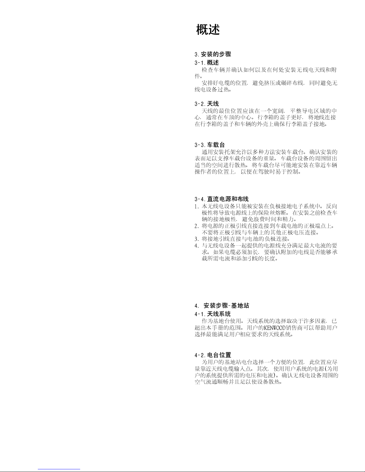
When you modify your radio as described in system set-
up, take the following precaution.
The rating of pin 7 (SB) of the accessory connector cable
(KCT-19) on the rear of the radio is 13.6V (0.75A). Insert a 1A
fuse if you use the SB pin for external equipment.
Accessory connector
cable (KCT-19)
GENERAL /
1
7
13
15
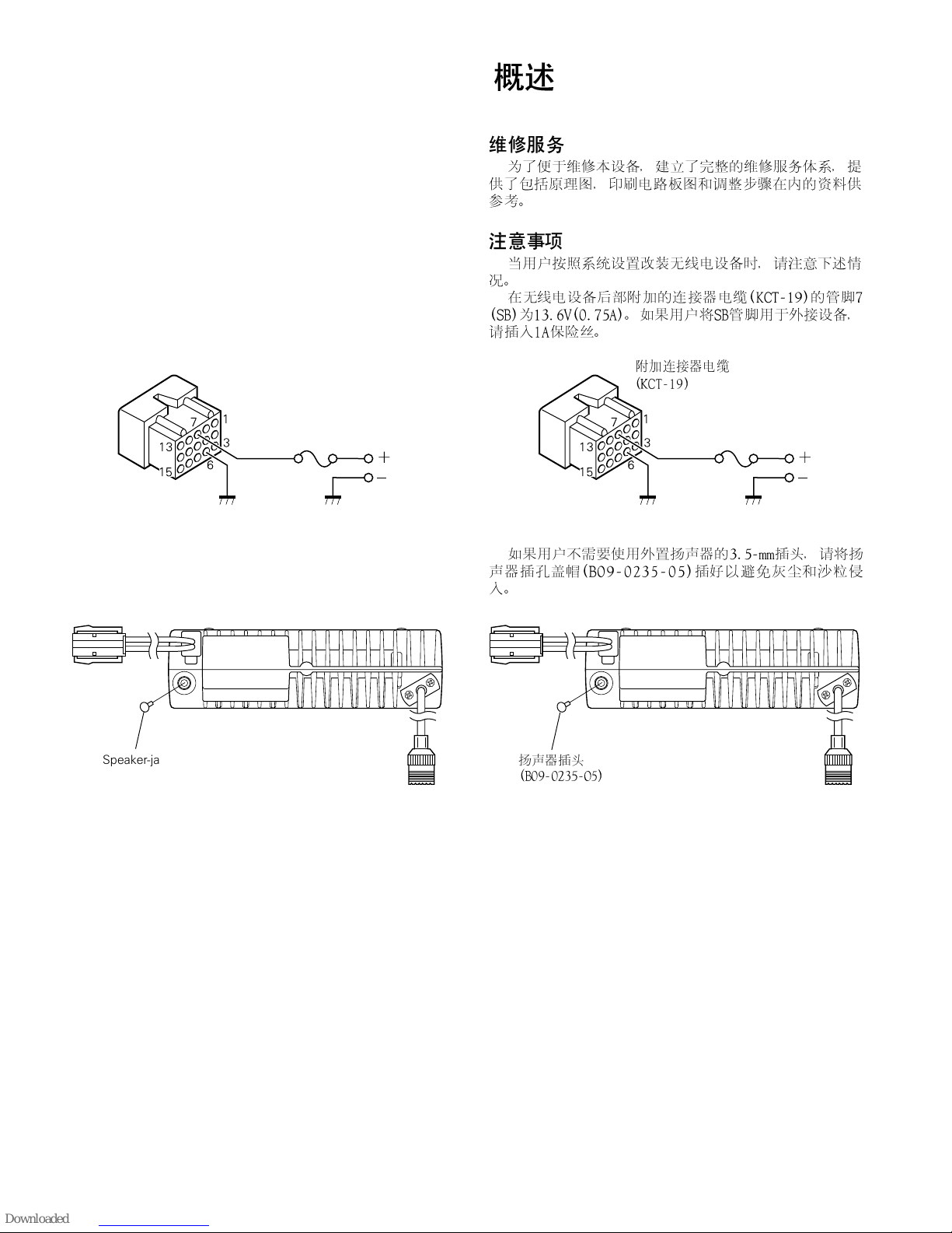
If you do not intend to use the 3.5-mm jack for the exter-
nal speaker, fit the supplied speaker-jack cap (B09-0235-05)
to stop dust and sand getting in.
Speaker-jack cap
(B09-0235-05)
3
6
+
13
15
1
7
3
6
+
4
OPERATING FEATURES /
1. Operation Features
The TK-782 is a VHF FM radio designed in DTMF/DMS
model.
This transceiver can handle up to 250 groups with 250
channels in each group.
You can use option signalling which is DTMF or DMS (Digital Message System-FFSK signalling) for every channel.
2. Transceiver Controls and Indicators (Fig. 1)
2-1. Front Panel Controls
All the keys on the front panel are momentary-type push
buttons. The functions of these keys are explained below.
TK-782
! POWER key
Transceiver POWER key. When the power is switched
off, all the parameters, such as the group and channel, are
stored in memory. When the power is switched on again,
the transceiver returns to the previous conditions.
! CHANNEL UP/DOWN key
! CALL key (Programmable)
!" key (Programmable)
! A, B, C and D key (Programmable)
! VOLUME UP/DOWN key (Programmable)
! BUSY/TX LED
The BUSY indicator (Green LED) shows that the channel
is in use. The TX indicator (Red LED) shows that you are
transmitting.
2-2. Programmable Keys
The FPU (KPG-77D) enables programmable keys to select
the following functions.
!
!
!
!
!
!
!
" Auto Dial
To transmit the stored DTMF code automatically. When
you select DTMF encode in the “Auto dial mode” menu, Auto
dial, Redial, Dial ID and Store Send modes are available.
Press the [Auto dial] key to enter the “Auto dial mode”.
Select the desired number to send. It is use the [Channel
up] and [Channel down] keys, or the [2] and [8] keys on the
microphone to select. Press the [
bers.
] key to transmit the num-
*
"
5
TK-782
OPERATING FEATURES /
" Auto Dial Programming
You can store the DTMF code and name, or erase it at the
transceiver.
! To store a DTMF code
Press the [Auto dial programming] key to enter “Auto dial
programming mode”. Select the desired memory number
you wish to store.
Press the [
(Enter auto dial memory name).
Press the [
the DTMF codes you want to store.
Press the [
confirms that the numbers are stored in the memory.
] key to select the desired memory number
*
] key to store the memory name. Now, enter
*
] key to store the numbers. A beep sound
*
! To erase the stored DTMF code
Press the [Auto dial programming] key to enter “Auto dial
programming mode”.
Press the [#] key to enter “Auto dial clear mode”. Select
the memory number you want to erase.
Press the [
“Auto dial clear mode”.
] key to erase the stored numbers and exit
*
" AUX A
If this key is pressed, “AUX” icon lights on the LCD and
Horn alert port which is inside of the transceiver turns to the
high level. If pressed again, the “AUX” icon goes off and the
Horn alert ports turns to the lower level.
"
!
!
"
" AUX B
This function can be programmed when the voice scram-
bler board is not installed.
If this key is pressed, an underscore (“_”) appears at the
extreme right of the LCD and OPT port which is inside of the
transceiver turns to the active level (low). If pressed again,
the underscore disappears and the OPT ports turns to the
deactive level (high).
" Channel Name
Press this key to switch between the “Channel name” and
“Grp #/Ch #” for the display. If no channel name is programmed, the transceiver automatically displays the group #/
channel #.
" Channel Up/Down
When this key is pressed each time, the channel number
to be selected is increased/decreased and repeats if held for
one second or longer.
" Channel Entry
You can directly recall the channel using the numeric key-
pad without using the [Channel up], [Channel down].
To access the channel directly, enter 1 to 3 digit numbers,
depending on the number of the programmed channels.
For example, if the radio has 199 programmed channels
(the maximum channel number is a 3-digit number) and you
would like to recall channel 5, you must enter [0],[0],[5]. If
the radio has 99 channels (2-digit number), you must enter
[0],[5] to access channel 5.
6
"
"
"
"
OPERATING FEATURES /
TK-782
" Display
Press the this key toggle the display function on/off. The
function backups when the transceiver turns on/off.
" Emergency Call
Pressing this key causes the transceiver to enter the emergency mode. The transceiver jumps to the programmed
“Emergency group/channel” and transmits for programmed
“Duration of transmission time”.
The transceiver disables microphone mute while transmitting. After finishing transmission, the transceiver receivers for programmed “Duration of receiving”. The transceiver
mutes the speaker while receiving. Following the above sequence, the transceiver continues to transmit and receive.
You can select whether or not the emergency ID is transmitted in the emergency mode.
" Fixed Volume
This function is used for changing the volume level, it is
power on tone, control tone, warning tone, alert tone, AF
volume type.
If these tone is set up in “Fixed”, the tone level can be
changed when [Fixed volume] key is pressed. When [Fixed
volume] key is pressed, tone level changes in turn to low
(tone volume low), high (tone volume high) and off.
"
"
"
" Group Up/Down
When this key is pressed each time, the group number to
be selected is increased/decreased and repeats if held for
one second or longer.
" Home Channel
Press this key once, the channel switches to the
preprogrammed home channel.
" Key Lock
Key lock prevents accidental operation of the transceiver.
When key lock is activated, all keys other that PTT, Emergency, Monitor, Monitor momentary, Shift, Squelch momentary and Volume up/down, are locked.
“LOCKED” appears momentarily when the [Key lock] key
is pressed.
" Monitor
When this key pressed once, “MON” icon lights and
squelch unmutes if a carrier is present, regardless of the
specified signalling (including option signalling).
If press again, “MON” icon goes off and squelch mutes.
" Monitor Momentary
While pressing this key, “MON” appears and the squelch
unmutes if a carrier is present, regardless of the specified
signalling (including option signalling).
If released, “MON” disappears, and the squelch mutes.
"
"
"
"
"
7
TK-782
OPERATING FEATURES /
" Operator Selectable Tone
When this key is pressed, the “OST” appears and encode/
decode QT/DQT is switched to the OST tone pair. If pressed
again, the “OST” display goes off and encode/decode QT/
DQT returns to transceivers preset.
When this key is held down for one second, the trans-
ceiver enters “OST select mode”. In this mode, the display
shows OST No. or OST name which is set to the channel and
operator can select one of OST tone pair using [Channel up],
[Channel down] key.
If pressed this key again, the displayed OST code is memo-
rized to the channel, the transceiver exits from the OST select mode, returns to normal channel display and “OST” display.
16 kinds of OST tone pairs can be programmed in the
operator selectable tone window. While in the OST select
mode, the transceiver does not look back at the priority channel in the scan resume mode.
" Queue
Press [Queue] key to toggle Queue mode on or off. When
it is on, you will see the contents of the queue buffer. You
can scroll the queue buffer using the [Channel up], [Channel
down] or [2]/[8] keys on the microphone.
When you are in Queue mode, [D] or [6] key to toggle the
Selcall and Status displays. When you are in Queue mode,
press the [C] or [4] key to toggle the Code and Selcall/Status
displays.
Hold down the [D] or [6] key to delete the top stack of the
Queue buffer. Hold down the [C] or [4] key to cancel Queue
mode and return to normal operation.
"
"
" Radio Password
Backup is done even if the power supply is cut off. A lock
is not canceled unless a proper password is inputted. The
character which can be inputted is to 6 digits with the number of 0 to 9. A lock is canceled if it is the same as code set
up at “Optional feature - Radio password”.
If the entered radio password is incorrect, the “Key input
error tone” sounds and the transceiver remains in “LOCK1”
screen.
" Scan
Press the [Scan] key to toggle scanning the channels on
and off. When the transceiver is scanning, “Revert channel
display” is temporary disabled and the SCN icon and
“#SCAN#” appear.
" Scan Delete/Add
Press the [Scan del/add] key to temporarily delete or add
each channel from/to the scan list. When a channel is added
to the scan list,“ ” appears on LCD.
When the transceiver exits Scan mode, the added or de-
leted channels are erased from the scan list. The original
scan list is restored.
"
"
"
8
OPERATING FEATURES /
TK-782
" Selcall Entry
Press [Selcall entry] key to enter the desired Selcall code
you want to call.
A transceivers unit ID is defined by a combination of 3digit fleet and 4-digit ID numbers.
To enter Selcall number, use the keypad (keypad model)
or use the [Channel up], [Channel down] keys to select a number. Then press [C] key to enter the selected number. The
selected digit will shift left to enter the next digit.
Press [D] key to move the cursor 1 position right. Hold
down [D] key ([6] key on a keypad) to clear the entered number.
" Selcall List
Press [Selcall list] key to enter Selcall list mode.
The ID list code of DMS will appear on LCD.
To select the Selcall list, use [Channel up]/[Channel down]
key or [2]/[8] key on the microphone keypad.
" Selcall + Status Entry
Select the selcall number you wish to call. Press [Selcall
+ Status entry] key to enter “Selcall entry mode”. It works as
“Selcall entry mode” mode. If you press [CALL] or [*] key
again, it works as “Status entry mode”.
" Selcall + Status List
Select the selcall number you wish to call. Press [Selcall
+ Status list] key to enter “Selcall list select mode”. It works
as “Status list” mode. If you press [Selcall + Status list] key
again, it works as “Status list select mode”.
"
"
"
"
" Send GPS
You can send the GPS location data manually. To perform
the operation, you have to install a GPS receiver with NMEA0183 output. (GPS receiver must be installed.)
" Shift
It allows you to enable [Shift + Function] key access. When
[Shift] key is pressed, SFT appears on LCD.
" Squelch Momentary
Press [Squelch momentary] key to force the squelch
unmute. “MON” icon appears on LCD and BUSY LED (Green)
lights. If released, the squelch unmutes and “MON” disappears. Also, BUSY LED (Green) goes off.
" Squelch Off
Press [Squelch off] key to force the squelch unmute.
“MON” icon appears on LCD and BUSY LED (Green) lights.
If the key is pressed again, the squelch unmutes and “MON”
disappears. Also, BUSY LED (Green) goes off.
" Talk Around
When Talk around function is activated, “TA” appears and
the transceiver transmits on the receive frequency, using
receiver’s QT/DQT code.
The operator can call the other party directly (without repeater).
"
"
"
"
"
9
TK-782
OPERATING FEATURES /
" None
When you press this key, the transceiver emits the “Key
input error tone” (no function is performed).
" Volume Up/Down
When this key is pressed, the volume level is increased/
decreased and repeats if held for 200ms or longer.
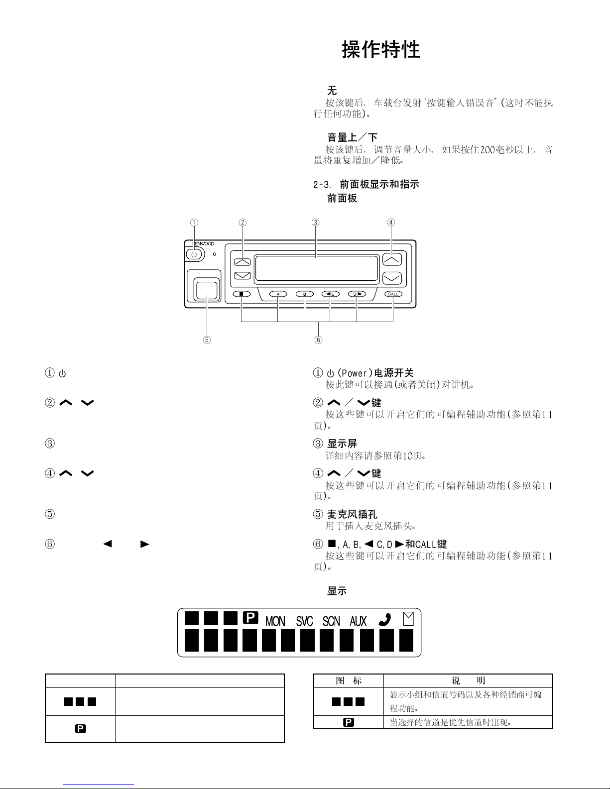
2-3. Front Panel Displays and Indicators
" Front Panel
(Power) switch
Press to switch the transceiver ON (or OFF).
"
"
"
/ keys
Press these keys to activate their programmable auxiliary
functions (page 11).
Display
See page 10 for more information.
/ keys
Press these keys to activate their programmable auxiliary
functions (page 11).
Microphone jack
Insert the microphone plug into this connector.
", A, B, C, D , and CALL keys
Press these keys to activate their programmable auxiliary
functions (page 11).
" Display
Indicator Description
Displays the group and channel numbers as
well as various dealer programmable functions.
Appears when the selected channel is a
priority channel.
"
10
OPERATING FEATURES /
Indicator Description
Appears when you press key programmed
as Monitor.
This icon is not used on this transceiver.
Appears while you are in Scan mode.
Appears when you activate the auxiliary function.
This icon is not used on this transceiver.
Appears when a message is stored in the
queue memory. Flashes when you receive
a new message.
Displays the group and channel number or
name (which your dealer can program with
up to 10 characters) as well as received
messages when using DMS. The left most
display is used as an add indicator ( ) and
the right most display is used for Selective
Call (
). The add indicator shows the
*
channels that are not locked out of the
scanning sequence. Selective Call is a
dealer programmable optional function.
TK-782
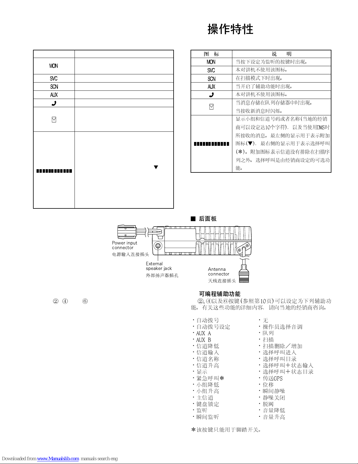
" Rear Panel
Power input
connector
External
speaker jack
" Programmable Auxiliary Functions
Keys , , and (page 10) can be programmed with
the auxiliary functions listed below. Please contact you dealer
for further details on these functions.
$ Auto Dial $ None
$ Autodial Programming $ Operator Sel Tone
$ AUX A $ Queue
$ AUX B $ Scan
$ Channel Down $ Scan Delete/Add
$ Channel Entry $ Scan Entry
$ Channel Name $ Selcall List
$ Channel Up $ Selcall + Status Entry
$ Display $ Selcall + Status List
$ Emergency Call* $ Send GPS
$ Group Down $ Shift
$ Group Up $ Squelch Momentary
$ Home Channel $ Squelch Off
$ Key Lock $ Talk Around
$ Monitor $ Volume Down
$ Monitor Momentary $ Volume Up
"
"
Antenna
connector
* : This key can be assigned only to a foot switch.
11
TK-782
OPERATING FEATURES /
3. Scan Operating
" Scan types
! Single group scan
You can scan all valid (ADD) channels in the displayed
group that can be selected with the group up/down key.
"
!
! Multiple group scan
You can scan all valid (ADD) channels in the all valid (ADD)
group.
" SCAN start condition
One or more non-priority channels must be added to all
channels that can be scanned. The transceiver must be in
normal receive mode (PTT off).
When you activate the key programmed to the scan func-
tion, the scan starts. The scan icon “SCN” lights and
“#SCAN#” or revert channel (programmable) is indicated
on alphanumeric display.
" Scan stop condition
The scan stops temporarily if the following conditions are
satisfied.
1) A carrier is detected, then signalling matches on channels for which receive the signalling is set by the programming software.
2) A carrier is detected on the channels for which receiving
signalling is not set by the programming software or when
the monitor (signalling cancel) function is activated.
" Scan channel types
1) Priority channel is the most important channel for the scan,
and always detects a signal during scan and when the
scan stops temporarily.
2) Non-priority channels detects a signal during scan. For
the channels that can be selected with the group or channel up/down key when the scan does not occur, adds an
indicator “
” lights.
!
"
"
"
" Priority channel setting
A priority channel can be set as follows with the program-
ming software.
1) Specify a priority channel as a fixed priority channel.
2) Make a selected channel, a priority channel.
" Scan type according to the priority channel
1) When no priority channel is set : Only the non-priority channels are scanned.
If a non-priority channel stops temporarily, it stops until
there is no signal on the channel.
2) When priority channel is set : Either priority channel is
scanned.
If a non-priority channel stops temporarily, a priority channel signal is detected at certain intervals.
If a priority channel stops temporarily, it stops until there
is no signal on the priority channel.
12
"
"
OPERATING FEATURES /
TK-782
" Revert channel
The revert channel is used to transmit during scanning
and set by the programming software.
1) Priority
The transceiver reverts to the priority channel.
2) Priority with talkback
The transceiver reverts to the priority channel.
If you press PTT during a resume timer (dropout delay
time, TX dwell time) or calling, you can transmit on current channel to answer to the call however revert channel
is set to priority channel.
After resume time, scan re-starts and transmission channel is return to priority channel.
3) Selected channel
The transceiver reverts to the channel before scanning or
the channel that you changed during scan.
4) Last called channel
The transceiver reverts to the last called channel during
the scan.
5) Last used channel
The transceiver reverts to the last used (transmitted) channel during scan. “Last used” revert channel includes
talkback function.
6) Selected with talkback
The transceiver reverts to the channel before scanning or
the channel that you changed during scan.
"
" Scan end
When you reactivate the key programmed to the scan func-
tion during scan mode, the scan ends.
The scan icon “SCN” and “#SCAN#” or revert channel
(programmable) display goes off.
" Temporarily delete/add
It is possible to delete or add channel temporarily during
scan. When scan stops on unnecessary channel for example
by interference of the other party, activate the delete/add function (for example press the key), then that channel is deleted
temporarily and scan re-start immediately.
When you would like to add the deleted channel temporarily to scan sequence, select the desired (deleted) channel
during scan, activate the delete/add function (for example
press the key) before scan re-start.
That channel is added temporarily to scan sequence. The
temporary deleted or added channels are returns to pre-set
delete/add, when the transceiver exits from scan mode.
" Keypad operation
This parameter selects the default use of the numerical
field of the keypad. You can select from “DTMF”, “Selcall
entry”, “Status entry” and “OST”.
In the case of “OST”; Enter to use the keypad to recall
OST directly. To recall OST memory 1 to 9, press the OST
number directly for 1 second. To recall OST memory 10 to
16, press [
Example; Recall OST memory 15 : [
When OST memory is recalled by keypad [1] to [9], the
“OST” display lights and OST is turned on. If the keypad [#]
is pressed, OST is turned off, and the “OST” display goes off.
] for 1 second, then press [0] to [6].
*
] [5]
*
"
"
"
13
TK-782
OPERATING FEATURES /
" Squelch logic signal
This signal is useful for external radio control units which
require a signal at the time of carrier operate relay or tone
operate relay.
" TX sense
Select one of the following three output functions for data
communication.
! MIC PTT
Indicates the state of the microphone PTT.
MIC PTT on = Low, MIC PTT off = High
! Ext PTT
Indicates the state of the Acc PTT input.
Ext PTT on = Low, Ext PTT off = High
! TX line
Indicates the actual transmitter activity.
TX on = Low, TX off = High
" MIC hook logic signal
The MIC hook logic signal is on the CODE 2 terminal. The
MIC hook logic signal type is the type of active low or high
for the MIC hook logic signal.
"
"
!
!
!
"
" Unlock logic signal
The PLL unlock logic signal is on the CODE 1 terminal.
The unlock logic signal type is the type of active low or high
for the PLL unlock logic signal.
" Com port
! Com 0
This function selects the external serila port function at
the microphone jack (TXD/RXD). PC programming is accepted, regardless of this setting.
! Com 1
This function selects the external COM1 pin serial port
function on the KCT-19 accessory jack. If the transceiver is
installed GPS unit, this function must be set up in “GPS”.
! Com 2
This function selects the external COM2 pin serial port
function on the KCT-19 accessory (RXD2 (AHK)/TXD2 (PTT))
and the external serial port function (TXD2/RXD2).
4. Details of Features
" Time-out timer
The time-out timer can be programmed off or in 30 sec-
onds increments from 30 seconds to five minutes. If the
transmitter is keyed continuously for longer than the programmed time, the transmitter is disabled and a warning tone
sounds while the PTT button is held down. The alert tone
stops when the PTT button is released.
"
"
!
!
!
"
14
OPERATING FEATURES /
TK-782
" Sub LCD display
You can use 3-digit the display to display the channel number or group number. It is useful when the main (12-digit)
display indicates group or channel name or other functions.
" Selective call alert LED
You can select whether or not the LED on the transceiver
flashes in an orange color when selective call was occurred.
" PTT ID
PTT ID provides a DTMF or FFSK (DMS : Fleet-ID) ANI to
be sent with every time PTT (beginning of transmission, end
of transmission, or both).
You can program PTT ID “on” or “off” for each channel.
The contents of ID are programmed for each transceiver.
The timing that the transceiver sends ID is programmable.
BOT : DTMF ID (BOT)/FFSK ID is sent on beginning of
transmission.
EOT : DTMF ID (EOT)/FFSK ID is sent on end of transmis-
sion.
Both : DTMF ID (BOT)/FFSK ID is sent on beginning of
transmission and DTMF ID (EOT)/FFSK ID is sent on end
of transmission.
" Radio password
When the password is set in the transceiver, user can not
use the transceiver unless enter the correct password.
This code can be up to 6 digits from 0 to 9 and input with
the key, and [CALL] key.
"
"
"
"
" Off hook decode
If the Off hook decode function has been enabled, removing and replacing the microphone on the hook has no effect
for decoding QT/DQT and option signalling.
" Timed power off
This function works as “Automatic Power Switch Off”.
Timed power off timer starts from the ignition-off. After
the timer expires, the radio will automatically turn off. The
timer will be reset if the ignition is turned on and off.
This function requires ignition-sense. Connect the ignition-line to the 9-pin connector which is located at the rear of
the radio.
After the timer expires, press the power switch to turn on
the radio.
" “TOT” pre-alert
The transceiver has “TOT” pre-alert timer. This parameter
selects the time at which the transceiver generates “TOT”
pre-alert tone before “TOT” is expired.
“TOT” will be expired when the selected time passes from
a TOT pre-alert tone.
" “TOT” re-key time
The transceiver has “TOT” re-key timer. This timer is the
time you can not transmit after “TOT” exceeded. After “TOT”
re-key time expired you can transmit again.
"
"
"
"
15
TK-782
OPERATING FEATURES /
" “TOT” reset time
The transceiver has “TOT” reset timer. This timer is the
minimum wait time allowed during a transmission that will
reset the “TOT” count.
“TOT” reset time causes the “TOT” to continue even after
PTT is released unless the “TOT” reset timer has expired.
" OST (Operator Selectable Tone)
The transceiver is capable to have “OST” function and 16
tone pair (QT/DQT) with max 10-digit name for each tone
pair.
! “OST” back up
The transceiver is programmable the selected “OST” code
is memorized or not. If you set to Disable (no memorized),
the “OST” function always starts at “off”.
" Clear to transpond
The transceiver waits the transpond of DTMF if channel is
busy until channel open. This feature prevents the interference to other party.
5. Option Signalling (DTMF)
Built-in DTMF decoder is available for option signalling.
It is possible to use individual call, group call, stun, kill.
Stun and kill are used with DTMF.
If the option signalling matches, a predetermined action
will occur.
If option signalling matches on a group/channel which is
set up with option signalling, the option signalling indicator
) will flash and option signalling will be released. The
(
*
transpond or alert tone will sound.
If the selective call alert LED is set up, the orange LED will
flash.
While option signalling matches (or if option signalling is
deactivated when you are transmitting), you can mute or
unmute ID/QT/DQT/Carrier.
"
"
!
"
" AND/OR
Option signalling match conditions can be selected with
AND/OR logic.
Alert/Transpond
AND Triggers at match with QT/DQT/ID+DTMF; Both
OR Triggers only for match with DTMF; Option
AF mute open
AND Triggers at match with QT/DQT/ID+DTMF; Both
OR Triggers only for match with QT/DQT/ID; Signalling
Even if set for OR, AF mute cannot be canceled just by a
match with DTMF.
In channels not set with QT/DQT, signalling is a match
just by rceiving the carrier.
16
"
OPERATING FEATURES /
TK-782
" Auto Reset
If option signalling matches a group set up with option
signalling, option signalling is released. After matching option signalling, option signalling will temporarily reset automatically.
" Stun/Kill
If the stun code matches, a predetermined action will oc-
cur. Whether option signalling is activated or not, when stun
code matches on any channel, the transceiver will become
stun or kill.
While stun is active (“LOCK2” appears), if the stun code +
“#” code is received, stun will disactive. While kill is active
(“ERROR” appears), the transceiver will be disable all functions. The transceiver must be reprogrammed by the FPU
(KPG-77D) to operation again.
6.
Alphanumeric Two-way Paging Function
(Digital Message System : DMS)
" General
The Alphanumeric Two-way Paging Function (DMS) is a
Kenwood proprietary protocol. It enables a variety of paging
functions.
" ID Construction
A radio unit ID is defined by a combination of 3-digit Fleet
and 4-digit ID numbers. Each radio unit must be assigned its
own Fleet and ID numbers.
"
"
"
"
" PTT ID
A pre-programmed unique ID can be sent at the begin-
ning of transmission and/or the end of transmission to identify which radio unit is on air.
" Selective Call (SELCALL)
This is a voice call to a particular individual or group of
stations.
! Example of call types;
[100][ALL ] : <Fleet Call>
All the units whose fleet number is “100” are called.
[100][1000] : <Individual Call>
The unit, whose the fleet number is “100” and ID number
is “1000”, is called.
[ALL][ALL ] : <Broadcast Call>
All the units are called.
[ALL][1000] : <Supervisor Call>
All ID “1000” are called regardless of their fleet number.
! Unit ID Encode Block
Encode ID Block can be set to limit manual dial ID. The
radio unit will not accept an ID other than these IDs which
are entered from the keypad. If Inter-fleet Call is enabled,
block ID setting affects each fleet group.
"
"
!
!
17
TK-782
OPERATING FEATURES /
" Status Message
Using a 2-digit number, you can send and receive a Status
message which may be decided in your talk group. Each
Status may be displayed with 16 alphanumeric characters if
programmed in the radio. A maximum of 15 received messages can be stored in the stack memory, and it can be reviewed after reception. If the message memory becomes
full, the oldest one will be erased. The stack memory will be
cleared by turning radio power off.
! Status 80~99 (Special)
Status numbers from 80 to 99 are reserved for special
purposes. Entering these statuses from the DTMF keypad
can be inhibited.
Please notice that the following status numbers are used
for special purposes;
80~89 : Reserved for future use.
90 : Remote kill on. Disable all transceiver functions.
91 : Remote stun on. The transceiver cannot operate.
92 : Turns stun off.
93 : Spare.
94 : Acknowledgement status sent when the radio unit is
in stun mode.
95~98 : Reserved for future use.
99 : Emergency Status.
"
!
Note : Remote stun works with DTMF stun function also.
! Automatic Status Response
If you pre-select a status number and leave the radio in
the Status Mode, it can automatically respond with the selected status number upon request from the base station.
(The request function is initiated by serial control on the base
station (Optional).)
" Short Messase (Optional)
A maximum of 48 characters can be sent (External equip-
ment is required). Received Short Messages will be displayed
in the same manner as a Status Message. A maximum of 15
received messages can be stored in the stack memory. In
the Stack Mode, 3-digit LCD indicates the received Short Message as “Q1”~“Q15”.
" Long Message
A maximum of 4096 characters can be sent (External
equipment is required). Received Long Message will not be
displayed or stacked in the radio memory but is output
through the COM (Data) port.
" Emergency Function
Emergency status 99 will be sent at the beginning of each
emergency transmission.
!
"
"
"
! Emergency Status response
Either “Horn” or “Alert” can be selected for the called ra-
dio unit’s response to reception of status 99 which is used
as an emergency status.
18
!
OPERATING FEATURES /
TK-782
" Other Functions
! Manual Dial
Fleet, ID and Status numbers can be entered from DTMF
keypad. (DTMF microphopne is required.)
! Data TX with QT/DQT
Whether programmed QT/DQT is modulated or not with a
data transmission except for Selcall. A radio unit can receive
a data message regardless of QT/DQT if the receiving unit is
not scanning.
! DMS Baud Rate
FFSK data baud rate setting. The same rate must be set
as a communication partner.
1200bps :
Data communication is made in 1200bps. The communi-
cation area is much wider than 2400bps. Recommended
for repeater operation.
2400bps :
Data communication is made in 2400bps. The communi-
cation area is narrower than 1200bps, but it will decrease
the data traffic. Data rate 2400bps may not work properly
depending on the repeater’s characteristic.
! Inter-Fleet Call
Inter-fleet calls allow a radio of one fleet number to call a
radio with a different fleet number (radio users can manually
dial a unit ID with a different fleet number).
"
!
!
!
!
!
Status/Short/Long Message on Data Group/Channel
Status/Short/Long Message transmission is made whether
on the Data Group/Channel.
! Status/Short/Unit ID Message Serial Output
Whether a received Status/Short message or PTT ID is
outputed or not to serial port.
" GPS Report
A NMEA-0183 GPS unit must be installed.
! GPS Report Mode
GPS data can be sent automatically or upon request. Manually sending GPS data works regardless of this setting.
Auto : GPS data is sent both automatically and by re-
quest. GPS Auto TX Interval and GPS Time Mark must be
adjusted if required.
Poll : GPS data is sent upon request from dispatcher.
! GPS Report Interval
Interval time between automatic GPS data transmissions.
! GPS Time Mark (Per Mobile)
The amount of time from the 0 (zero) minute of the standardized GPS UTC time to starting the first transmission of
GPS data. It must be set to a different value for each radio
unit to avoid a transmission crash.
!
!
"
!
!
!
19
TK-782
OPERATING FEATURES /
! Send GPS
Pressing this key causes the transceiver to send a single
GPS data.
! GPS Report On Data Group/Channel
GPS data transmission is made on the Data Group/Chan-
nel in conventional format.
! Received GPS Data Output
Any selected sentence can be output through the radio
serial port (COM1).
1) MAP HEADER NMEA1 ($GPGGA), NMEA2 ($GPGLL),
NMEA3 ($GPRMC)
NMEA-0183 standard command. This should be set according to your PC application.
2) MAP HEADER KW1 ($PKLDS)
This is a Kenwood original sentence which consists of
“$GPGLL + Fleet + ID + Status”. This item should be set
according to your PC application.
3) MAP HEADER KW2 ($PKLID)
This is a Kenwood original sentence which consists of
“Fleet + ID”. This should be set according to your PC
application.
!
!
!
" Parameters
! GTC Count
Number of “Go To data Channel” messages to be sent
before transmitting a data message if it is being made on
Data Group/Channel. If a radio unit receives a GTC message, it will move to the Data Group/Channel of the current
group. Increase this item to make sure the called radio unit
moves to the Data Group/Channel.
! Random Access (Contention)
When a channel is busy, radio unit will not transmit (de-
pending on its Busy Channel Lockout setting). As soon as a
channel is cleared, some transmissions may crash. Random
access is used to avoid this by employing a random transmission sequence.
! Number of Retries
Number of Retries is the maximum number of retry trans-
mission when no acknowledgement is received in the Maximum ACK Wait Time. Increase this item to improve data
communication reliability.
! TX Busy Wait Time
TX Busy Wait Time is the maximum amount of time be-
fore giving up the data transmission when the channel is
busy. Also, this timer affects if it expires during Random
Access period.
"
!
!
!
!
20
OPERATING FEATURES /
TK-782
! Maximum ACK Wait Time
Maximum ACK Wait Time is the maximum amount of time
to wait for an acknowledgement from the called radio unit. It
is used as an interval time of retries. It must be set greater
than the ACK Delay Time of the called radio unit.
! ACK Delay Time
ACK Delay Time is the amount of time from the end of
receiving a data to the beginning of sending an
acknowledgement. It should be adjusted as the repeater’s
hang-up delay time. Also, it must be set less than the Maximum ACK Wait Time of the calling radio unit.
! TX Delay Time (RX Capture)
TX Delay Time is the amount of unmodulated transmission to let the called unit stop scanning or exit its battery
save mode. It is used only when starting a data communication sequence.
! Data TX Modulation Delay Time
Data TX Modulation Delay Time is the amount of time from
the beginning of transmission to the beginning of a data
modulation. It is used every time data is transmitted.
7. Audible User Feedback Tones
The transceiver outputs various combinations of tones to
notify the user of the transceiver operating state. The main
tones are listed below.
!
!
!
!
" Power on tone
This tone is output when the transceiver is turned on. (The
high tone is output for 500ms.)
" Alert tone
This tone is output when the transceiver is TX inhibition
for TOT, battery warning and PLL unlocked. It is output until
the PTT button is released.
" Group call tone
Sounds when a group call with the correct DTMF option
signalling is received.
" DMS signalling alert tone
Sounds when an individual call with the correct DMS signalling is received.
" Individual call tone
Sounds when an individual call with the correct DTMF
option signalling is received.
" Key press tone [A]
Sounds when a key is pressed. For toggle keys, sounds
when toggle function is turned on (key press tone [B] sounds
when it is turned off).
"
"
"
"
"
"
21
TK-782
OPERATING FEATURES /
" Key press tone [B]
Sounds when a key is pressed. For toggle keys, sounds
when the toggle function is turned off (key press tone [A]
sounds when it is turned on).
" Key press tone [C]
Sounds when a key is pressed. Also sounds when stor-
ing data, adding a DTMF code to memory, and when changing test mode settings.
" Key input error tone
Sounds when a key is pressed but that key cannot be
used.
" Roll over tone
Sounds at the smallest group/channel.
" Transpond tone
Sounds when an individual call with the correct DTMF
option signalling is received. For group calls, only the group
tone will sound, not the transpond tone.
" Pre alert tone
Sounds prior to the TOT TX inhibit activation. If TOT pre
alert is set, the tone sounds at the amount of time programmed, before the TOT expires (TOT time # TOT pre alert
time = Pre alert tone sounding time).
"
"
"
"
"
"
22
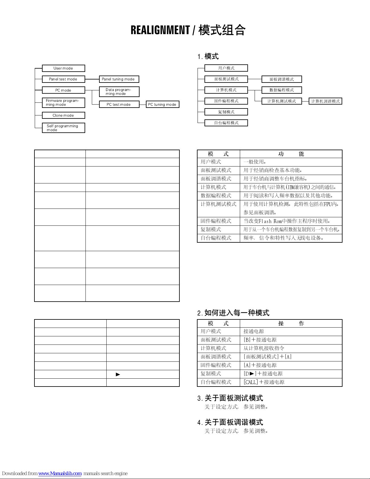
1. Modes
User mode
TK-782
REALIGNMENT /
Panel test mode
PC mode
Firmware program-
ming mode
Clone mode
Self programming
mode
Mode Function
User mode For normal use.
Panel test mode Used by the dealer to check the funda-
Panel tuning mode Used by the dealer to tune the radio.
PC mode Used for communication between the
Data programming Used to read and write frequency data
mode and other features to and from the radio.
PC test mode Used to check the radio using the PC.
Firmware program- Used when changing the main program
ming mode of the flash memory.
Clone mode Used to transfer programming data from
Self programming Frequency, signalling and features write
mode to the radio.
Panel tuning mode
Data program-
ming mode
PC test mode
ment characteristics.
radio and PC (IBM compatible).
This feature is included in the FPU.
See panel tuning.
one radio to another.
PC tuning mode
2. How to Enter Each Mode
Mode Operation
User mode Power ON
Panel test mode
PC mode Received commands from PC
Panel tuning mode [Panel test mode]+[A]
Firmware programming mode [A]+Power ON
Clone mode [D ]+Power ON
Self programming mode [CALL]+Power ON
[B]+Power ON
3. Panel Test Mode
Setting method refer to ADJUSTMENT.
4.Panel Tuning Mode
Setting method refer to ADJUSTMENT.
23
TK-782
REALIGNMENT /
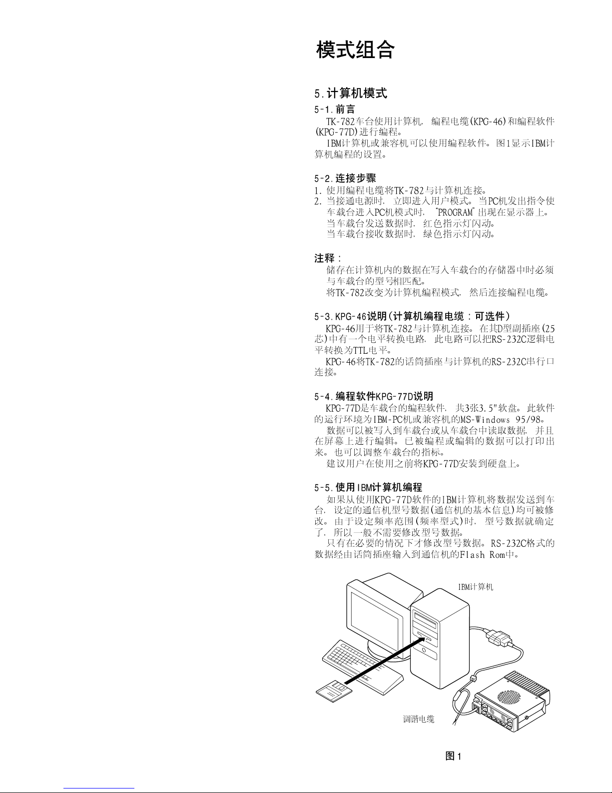
5. PC Mode
5-1. Preface
The TK-782 transceiver is programmed by using a personal
computer, a programming interface (KPG-46) and programming software (KPG-77D).
The programming software can be used with an IBM PC
or compatible. Figure 1 shows the setup of an IBM PC for
programming.
5-2. Connection Procedure
1. Connect the TK-782 to the personal computer with the
interface cable.
2. When the Power switch on, user mode can be entered
immediately. When PC sends command the radio enter
PC mode, and “PROGRAM” is dispalyed on the LCD.
When data transmitting from transceiver, the red LED is
blinking.
When data receiving to transceiver, the green LED is blinking.
!
!
Notes :
! The data stored in the personal computer must match
model type when it is written into the flash memory.
! Change the TK-782 to PC mode, then attach the interface
cable.
5-3. KPG-46 Description
(PC programming interface cable : Option)
The KPG-46 is required to interface the TK-782 to the com-
puter. It has a circuit in its D -subconnector (25-pin) case that
converts the RS-232C logic level to the TTL level.
The KPG-46 connects the modular microphone jack of the
TK-782 to the computers RS-232C serial port.
5-4. Programming Software KPG-77D Description
The KPG-77D is the programming software for the trans-
ceiver supplied on two 3.5” floppy disks. This software runs
under MS-Windows 95 or 98 on an IBM-PC or compatible
machine.
The data can be input to or read from the transceiver and
edited on the screen. The programmed or edited data can
be printed out. It is also possible to tune the transceiver.
We recommend that install the KPG-77D for example to
hard disk first then use it.
5-5. Programming With IBM PC
If data is transferred to the transceiver from an IBM PC
with the KPG-77D, the destination data (basic radio information) for each set can be modified. Normally, it is not necessary to modify the destination data because their values are
determined automatically when the frequency range (frequency type) is set.
The values should be modified only if necessary.
Data can be programmed into the flash memory in RS-
232C format via the modular microphone jack.
KPG-77D
IBM-PC
KPG-46
Tuning cable
24
TK-782
Fig. 1 /
REALIGNMENT /
6. Firmware Programming Mode
6-1. Preface
Flash memory is mounted on the TK-782. This allows the
TK-782 to be upgraded when new features are released in
the future. (For details on how to obtain the firmware, contact Customer Service.)
6-2. Connection Procedure
Connect the TK-782 to the personal computer (IBM PC or
compatible) with the interface cable (KPG-46). (Connection
is the same as in the PC Mode.)
6-3. Programming
1. Start up the programming software (Fpro. exe).
2. Set the communications speed (normally, 57600 bps) and
communications port in the configuration item.
3. Set the firmware to be updated by File name item.
4. Turn the TK-782 Power ON with the [A] switch held down.
Hold the switch down until the display changes to “PROG
57600”. When “PROG 57600” appears, release your fin-
ger from the switch.
5. Check the connection between the TK-782 and the per-
sonal computer, and make sure that the TK-782 is in the
Program mode.
6. Press write button in the window. A window opens on
the display to indicate progress of writing. When the TK-
782 starts to receive data, the
7. If writing ends successfully, the LED on the TK-782 lights
and the checksum is displayed.
8. If you want to continue programming other TK-782, re-
peat steps 4 to 7.
Notes :
! This mode cannot be entered if the Firmware program-
ming mode is set to Disable in the Programming software
(KPG-77D).
! When programming the firmware, it is recommend to copy
the data from the floppy disk to your hard disk before up-
date the radio firmware.
Directly copying from the floppy disk to the radio may not
work because the access speed is too slow.
icon is blinking.
TK-782
!
!
6-4. Function
1. If you press the ["] switch while “PROG 57600” is dis-
played, the version is displayed. If you press the ["] switch
again while the version is displayed, “PROG 57600” is
redisplayed.
2. If you press the [D
played, the display changes to “PROG 19200” to indicate
that the write speed is low speed (19200 bps). If you
press the [D
played, the display changes to “PROG 38400”, and the
write speed becomes the middle speed (38400 bps). If
you press the [D
displayed, the display returns to “PROG 57600”.
3. If you press the [D ] switch while the version is displayed,
the checksum is displayed. If you press the [D
again while the checksum is displayed, the version is
redisplayed.
] switch while “PROG 57600” is dis-
] switch again while “PROG 19200” is dis-
] switch again while “PROG 38400” is
Note :
Normally, write in the high-speed mode.
] switch
25
TK-782
REALIGNMENT /
7. Self Programming Mode
Write mode for frequency data and signalling etc. Mainly
used by the person maintaining the user equipment.
7-1. Channel Setting Mode
Each channel can be setup in its action mode by using
the panel keys.
! Pressing ["] while “SELF PROG” is diaplyed will change
to channel setting mode.
! Press [D
up/down] to change the selection.
! By pressing [
memory, and the next item appears. By pressing [D
the displayed information is not stored in memory, and
the next item appears.
! Press["] to return to the original display (“SELF PROG”).
The setup items for channel setting mode are listed be-
low.
] to select a setup item, then press [Channel
C], the displayed information is stored in
!
!
!
],
!
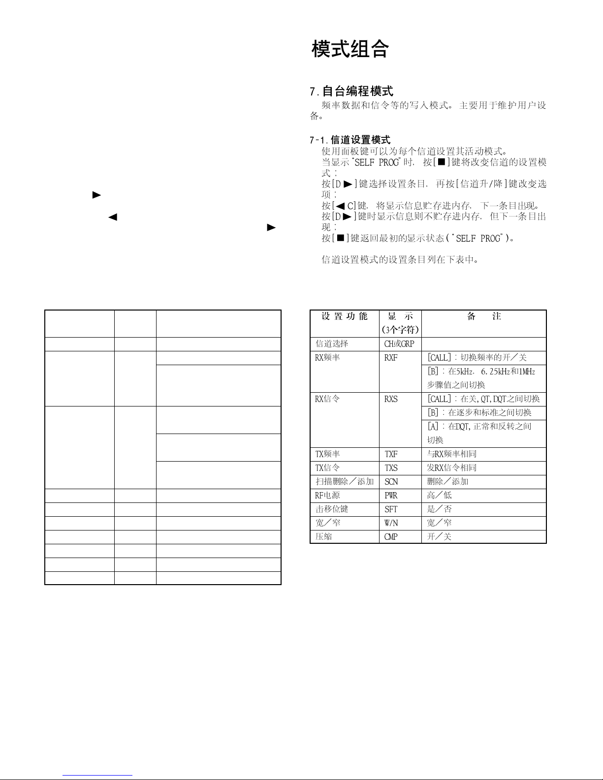
Setup function Display Remarks
(3 character)
Channel selection
RX frequency RXF
RX signalling RXS [CALL] : Switches between off,
TX frequency TXF Same as RX frequency
TX signalling TXS Same as RX signalling
Scan del/add SCN DEL/ADD
RF power PWR HIGH/LOW
Beat shift SFT YES/NO
Wide/Narrow W/N WIDE/NARROW
Compander CMP ON/OFF
CH or GRP
[CALL] : Switches frequency on/off
[B] : Changes the step value
between 5kHz, 6.25kHz, and
1MHz
QT, and DQT.
[B] : Switches between 1 step
and standard
[A] : Switches between DQT
normal and invert
26
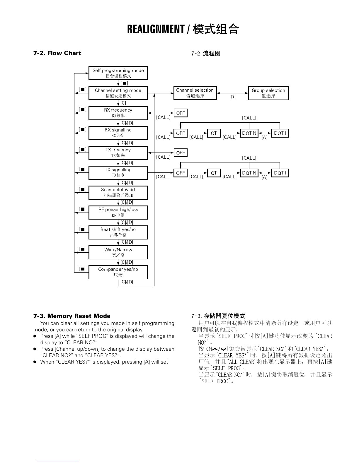
7-2. Flow Chart
Self programming mode
[]
Channel setting mode
[]
[]
[]
[]
[]
RX frequency
RX signalling
TX freuency
TX signalling
Scan delete/add
REALIGNMENT /
[]
[C]
[CALL]
[C]/[D]
[CALL] [CALL] [CALL]
[C]/[D]
[CALL]
[C]/[D]
[CALL] [CALL] [CALL]
[C]/[D]
Channel selection
OFF
OFF QT
OFF
OFF
QT
Group selection
[D]
[CALL]
DQT N DQT I
[CALL]
DQT N DQT I
TK-782
[A]
[A]
[C]/[D]
[]
[]
[]
[]
RF power high/low
[C]/[D]
Beat shift yes/no
[C]/[D]
Wide/Narrow
[C]/[D]
Compander yes/no
[C]/[D]
7-3. Memory Reset Mode
You can clear all settings you made in self programming
mode, or you can return to the original display.
! Press [A] while “SELF PROG” is displayed will change the
display to “CLEAR NO?”.
! Press [Channel up/down] to change the display between
“CLEAR NO?” and “CLEAR YES?”.
! When “CLEAR YES?” is displayed, pressing [A] will set all
data to default, and “ALL CLEAR” will appear on the dis-
play. Press [A] again to display “SELF PROG”.
! When “CLEAR NO?” is displayed, pressing [A] will cancel
the reset, and “SELF PROG” will be displayed.
!
!
!
!
27
 Loading...