

10 DISC DVD / CD CHANGER
KDV-C810/C820/
C830/C840/C860
© 2002-4 PRINTED IN JAPAN
SERVICE MANUAL
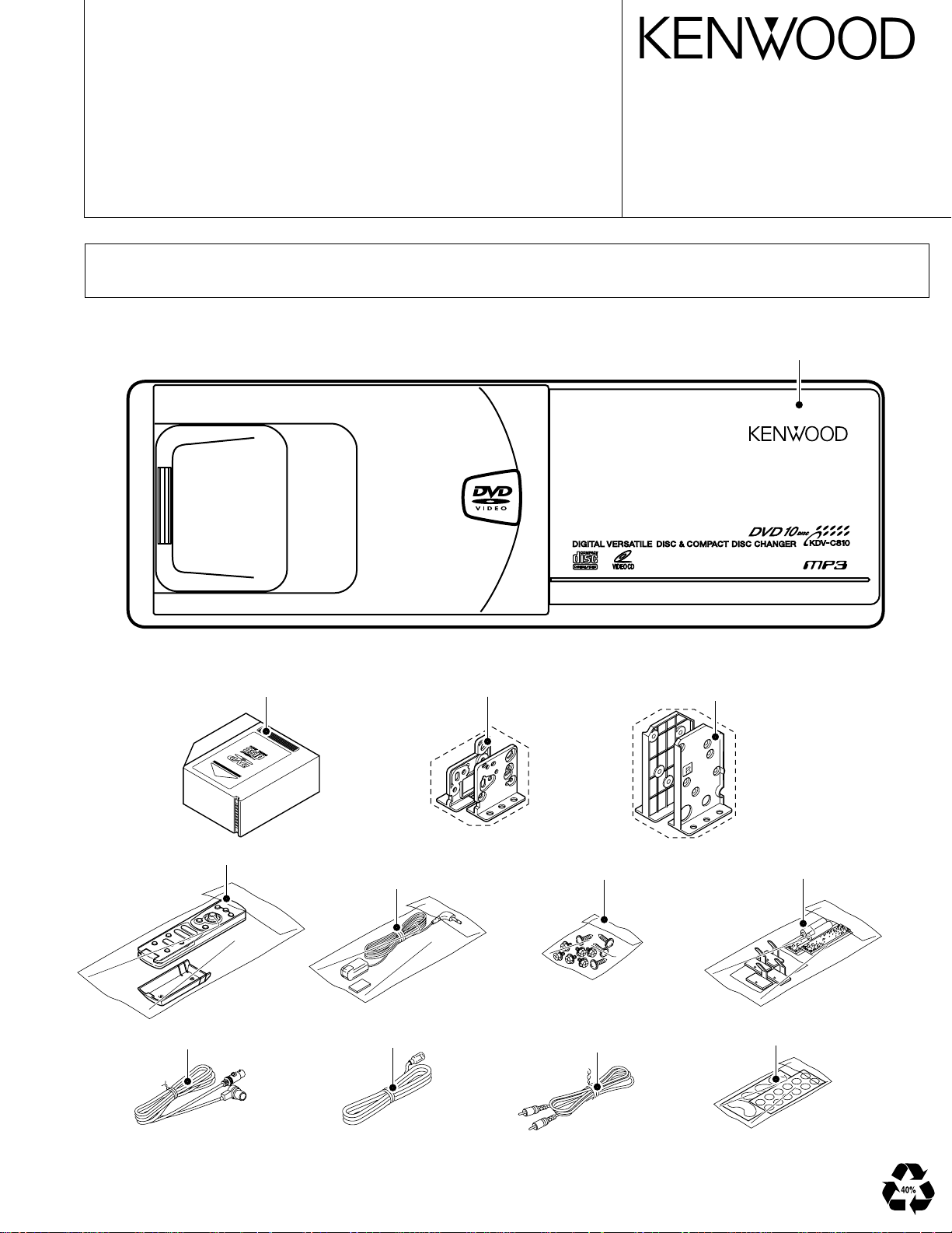
About the handling after repair (for transportation)
Please after repair for the units you must be internalized elevator mechanism of most below position (for magazine pack eject position)
and always attach CAUTION CARD and STEPPED SCREW (for transportation). In order to make an elevator mechanism downed.
B51-7953-00 (N) 3394
PANEL ASSY
A64-2965-08 : K type, A64-2966-08 : E type
A64-2967-08 : M type, A64-2968-08 : X type
A64-2969-08 : C type
MAGAZINE PACK ASSY
(J19-5211-08)
REMOTE CONTROL ASSY
RC-DV300
(A70-2038-08)
CORD WITH PLUG
(E30-6124-05)
BRACKET
(J19-5209-08)
REMOTE CONTROL
SENSOR ASSY
(T95-0235-05)
DC CORD
(E30-6148-08)
SCREW SET
(N99-1732-08)
VIDEO CORD
(E30-6149-08)
Illustration is KDV-C810
BRACKET
(J19-5210-08)
MOUNTING PARTS SET
(W06-0745-08)
PROTECTION SHEET
(H21-1146-08)
2
50MHz
X250
16MHz
X151
8.38MHz
X301
ACCACC DET
VCC5
VCC
VCC1
VBB
V5 BU
5V
11.5V
VIDEO DECODER
DOLBY AC3/
VCD,SVCD,
MPEG AUDIO/
AUDIO CD,
MP3 DECODER
DTS AUDIO DECODING
X551 27MHz
BU2 to MAIN UNIT
ACC to MAIN UNIT
VCC 2.8 D +5V
VCC5 to MAIN UNIT
VCC 5.0
VCC 3.3
VCC 3.3D
VCC 3.6
CONTROL
ACC 5V
ACC
BU
L052
L053
ACC 5V
V +5V
A +9V
BU1
BU to MAIN UNIT
L914
5L BUS
22.75MHz
X201
ATAPI I/F
TR COIL
FO COIL
EF
D
A
B
PD
C
M
M
M
IC1
SPINDLE
MOTOR
DRIVER
M
RF AMP/SERVO
CONTROL
IC101
Q102,103
LD DRIVER
IC102
FOCUS, FEED
TRACKING
DRIVER
IC202
1M DRAM
PROCESSOR
& DATA
CD/DVD SERVO
IC201
DECODER
DVD ROM
ATAP I/F &
IC250
IC251
4M DRAM
IC105
PULSE COUNT
FEED GEAR
IC152,153
RESET IC
IC305
DRIVER
LOADING
CONTROLLER
SERVO
PROCESSOR
IC151
IC301
CONTROLLER
PROCESSOR
MECHANISM
IC306
RESET IC
DRIVER
ELEVATOR
IC304
MOTOR
MOTOR
MICRO-
MICRO-
Q304
IC307
5V
Q301
5V
IC303
(SW301)
EJECT SW
DVD
PROCESSOR
IC501
IC514
IC511
DRAM
MEMORY
FLASH
EEPROM
IC591
VIDEO
IC571
VIDEO
182
IC561
AUDIO D/A
CONVERTER
IC101,111
LINE AMP
IC581
BUFFER
IC551
OPTICAL
PARKING
VIDEO
AUDIO
(SW901)
SETTING SW
PAL/NTSC
ENCODER DRIVER
IC181,
2.8V
IC081
5V
Q004
Q003
5V
Q002
3.3V
ACC
Q072
BACK UP
IC071
5V
5V
IC062 IC061
9V
IN
OUTPUT
OUT L/R
OUT F/R
CONTROL
HEAD
to
UNIT
DIN13P
REMOTE
FEED MOTOR
(VM2)
SPINDLE MOTOR
(VM1)
INSIDE SW
(SW4)
FEED SENSOR
(PHT2)
LOADING MOTOR
(VM3)
CLAMP
SW
(SW302)
LOAD OUT
SW
(SW1)
IN SW
(SW5)
MAGAZINE DISC
SENSOR
(D1)
(SW2)
UP SW
(SW3)
DOWN
(VM4)
ELEVATOR
MOTOR SENSOR
POSITION
(PHT1)
SW
(VPU1)
PICKUP ASSY
MAIN UNIT MPEG UNIT
MECHANISM ASSY
KDV-C810/C820/C830
/C840/C860
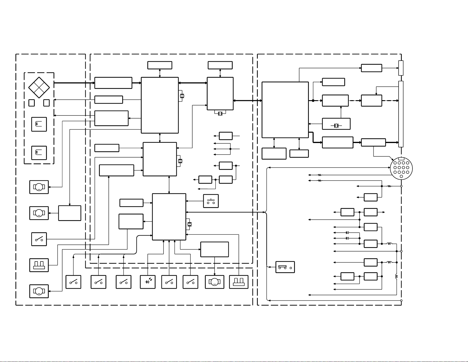
BLOCK DIAGRAM
KDV-C810/C820/C830
/C840/C860
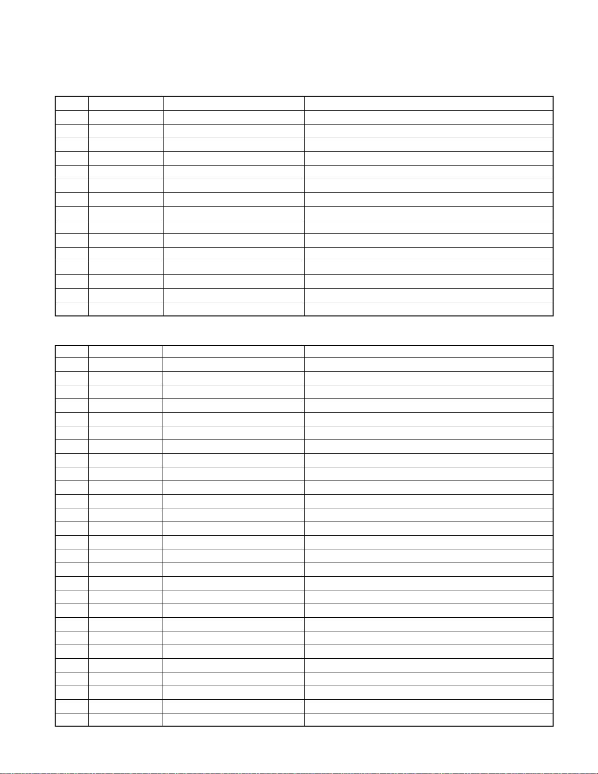
COMPONENTS DESCRIPTION
MECHANISM (SWITCH / SENSOR / MOTOR)
Ref.No.
SW1 S68-0858-08 LOAD OUT SW Disc tray return (magazine pack side) detect switch
SW2 S68-0858-08 UP SW Elevator unit topmost part (disc 1) detect switch
SW3 S68-0858-08 DOWN SW Elevator unit lowermost part (magazine eject position) detect switch
SW4 S68-0878-08 INSIDE SW Pickup unit inside position detect switch
SW5 S68-0858-08 MAGAZINE IN SW Magazine pack in detection switch
SW302 S74-0820-08 CLAMP SW Disc clamp operation end switch
VM1 - SPINDLE MOTOR Disc rotation drive motor
VM2 T42-1079-08 FEED MOTOR Pickup unit drive motor ( Feed motor)
VM3 T42-1080-08 LOADING MOTOR Disc tray loading / unloading drive motor
VM4 T42-1078-08 ELEVATOR MOTOR Elevator mechanism part drive motor
VPU1 T25-0227-08 LASER PICKUP 2 Laser pickup unit
PHT1 T95-0256-08 POSITION SENSOR Magazine tray position detect photointerruptor
PHT2 - FEED SENSOR Feed motor rotation detect photointerruptor
LED1 AN1102W-3 LED LED for disc detection
IC1 BA6849FP-Y SPINDLE MOTOR DRIVER Spindle motor driver
Component Name Application/Function Operation/Condition/Compatibility
MAIN UNIT
Ref.No.
IC101 TA1293F RF AMP/SERVO CONTROL RF amplifier / Servo control IC
IC102 BA5918FP-Y FOCUS/TRACKING/FEED DRIVER Focus/ Tracking coil, Feed motor driver
IC105 TC75S51F PULSE COUNT Feed motor rotation detection comparator
IC151 HD64F3039TEBL1
IC103 RN5RG33AA +3.3V AVR 3.3V regulator IC
IC104 MMDF2P01HD +5.0V AVR 5.0V regulator IC
IC152 TC7ST08FU BUFFER Reset signal buffer IC
IC153 IC-PST597EN RESET REGULATOR Reset signal regulator IC
IC154 TC7WU04FU BUFFER ATAPI interface buffer IC
IC108 LM50CIM3 TEMP DETECTOR Temperature detection thermistor
IC201 TC9453AF
IC202 LH61665AS-60E2 DATA BUFFER DRAM Data buffer DRAM
IC250 TC9469BF ATAPI I/F & DVD ROM DECODER ATAPI interface & DVD decoder
IC251 MSM514265C50TS DATA BUFFER DRAM Data buffer DRAM
IC301 UPD78F0034AGK9
IC302 S-24C04BFJ EEPROM Disc information data memory
IC303 L78M05TL +5.0V AVR 5.0V regulator IC
IC304 BA6289F ELEVATOR MOTOR DRIVER Elevator motor driver
IC305 BA6289F LOADING MOTOR DRIVER Loading motor driver
IC306 S-80732AN-DW RESET IC Reset IC
IC307 S81250HG-RD +5.0V AVR 5V power supply regulator IC for Microprocessor
IC308 S-80732AN-DW BATTERY DETECTOR Battery voltage detection IC
Q101 2SB1424-R CURRENT DRIVE 3.3V current drive transistor
Q102 2SA1338-5 DVD LD DRIVE Laser diode power supply for DVD
Q103 2SA1338-5 CD LD DRIVE Laser diode power supply for CD
Q151 DTA114YUA SW Flash rewriting permission changeover switch
Q152 2SA1338-5 DVD LD DRIVE DVD laser high frequency superposition circuit on-switch
Component Name Application/Function Operation/Condition/Compatibility
MICROPROCESSOR (SERVO CONTROLLER)
CD/DVD SERVO & DATA PROCESSOR
MICROPROCESSOR (MECHANISM CONTROL)
Servo IC control microprocessor
Digital-servo control IC
Mechanism control microprocessor
3
KDV -C810/C820/C830
/C840/C860
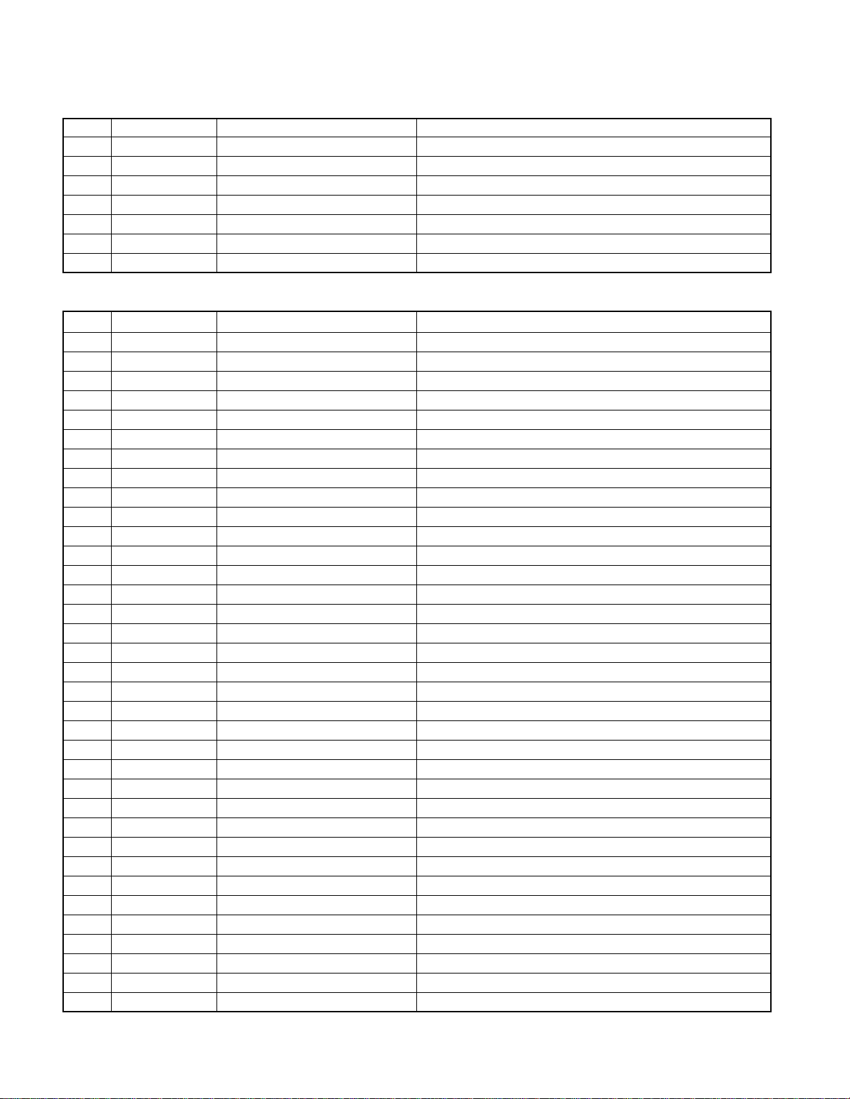
COMPONENTS DESCRIPTION
Ref.No.
Q301 2SB1424-R AVR FOR MECHANISM Mechanism power supply
Q302 DTC114YK POWER CONTROL SW Mechanism power supply control switch
Q303 DTA114YK ACC DETECTOR CONTROL SW ACC detection transistor (At the time of ACC detection : H)
Q304 2SC2412K-R ACC DETECTOR ACC detection transistor (At the time of ACC detection : ON)
Q305 DTC124EK RESET SW FOR MECHANISM Mechanism control microcomputer (IC301) reset switch
Q307 2SC2412K-R BATTERY DETECTOR Battery detection IC (It tur ns on at the time of 13 pin connection)
SW301 S70-0900-08 EJECT SW Magazine eject switch
Component Name Application/Function Operation/Condition/Compatibility
MPEG UNIT
Ref.No.
IC001 LTC1628CG D/D CONVERTER 3.3V / 5.0 V D/D converter
IC061 PQ09DZ1U +9.0V AVR 9.0V regulator IC
IC062 S81250HG-RD +5.0V AVR 5.0V regulator IC
IC071 S81250HG-RD +5.0V AVR 5.0V regulator IC
IC081 LM1117IMPX-ADJ +2.8V AVR 2.8V regulator IC
IC101 NJM4565M-B AUDIO SIGNAL BPF Audio signal BPF filter
IC111 NJM4565M-B AUDIO SIGNAL BPF Audio signal BPF filter
IC171 NC7S04P5 INVERTER (MUTING) Muting signal inverter
IC181 TK15405AM VIDEO SIGNAL DRIVER Video signal amp
IC182 TK15405AM VIDEO SIGNAL DRIVER Video signal amp
IC501 ES4428S DVD PR OCESSOR MPEG 2 video, audio processing DSP
IC511 HY57V641620HGT DRAM MPEG 2 data memory
IC514 MX29F800TTC-90 FLASH MEMORY System program memory
IC515 TC7S32FU OR GATE Signal selector IC
IC516 SN74AHC174PW-R SELECTOR Input selector IC
IC551 TC7WU04FU 27MHz OSC Crystal oscillator buffer (27MHz)
IC561 PCM1716E AUDIO SIGNAL D/A CONVERTER Audio signal D/A converter
IC571 AK8812 VIDEO ENCODER Video signal D/A converter
IC581 NC7ST08P5 DIGITAL OUT BUFFER Digital out signal buffer
IC591 HN58X2408FPIZ BACKUP MEMORY Backup memory
Q001 2SA1622-6 SW 3.3V and 5.0V power supply Control
Q002 FDS8936A +3.3V DRIVER 3.3V power supply drive
Q003 FDS8936A +5.0V DRIVER 5.0V power supply drive
Q004 DTA113ZUA +5.0V CONTROL SW 5.0V power supply control
Q051 DTC144EUA CHANGER CONTROL SW Changer control switch
Q052 DTA113ZUA MUTING CONTROL SW Muting signal ON/OFF
Q071 DTA114YUA SW Backup (BU) power supply ON/OFF
Q072
Q101,111,
151,161
Q171 DTA113ZUA MUTING CONTROL SW Muting transistor control (for Q111,161)
Q172 DTA113ZUA MUTING CONTROL SW Muting transistor control ( for Q101,151)
Q181 DTC144EUA PARKING SIGNAL DETECTOR Parking brake signal control (Parking H)
Q182 2SB709A (R) VIDEO SIGNAL BUFFER Video signal buffer
SW901 S62-0868-08 PAL/NTSC SETTING SW PAL/NTSC change-over switch (PAL : L / NTSC : H)
CT551 C05-0520-08 27MHz REF ADJ Reference 27MHz adjustment trimmer
Component Name Application/Function Operation/Condition/Compatibility
DTC144EUA/UMC2N
DTC323TU MUTING Audio signal muting transistor.
SW Control of Q71
4

KDV-C810/C820/C830
/C840/C860
MICROCOMPUTER’S TERMINAL DESCRIPTION
IC151 (MAIN UNIT : SERVO CONTROL)
Pin No.
14-20 D0-D7 I/O CPU data bus terminal IC201 and IC250 control data bus
22-28 HA0-HA6 O CPU address bus terminal IC201 and IC250 address bus
61-64
Pin Name I/O Purpose / Description Processing Operation
1 /RST0 O
2 /RST1 O CD/DVD Servo / Data processor reset output terminal Reset terminal 48PIN of IC201 (Active L)
3 SPSTBY O Spindle motor driver power save output terminal VM1 (spindle motor) control
7 MD2 I Operation mode change input terminal Connected to +5V
9 FLCNT O Flash memory write-in circuit ON output terminal Control of Q151
10 SB O Spindle motor short brake output terminal VM1 (spindle motor) control
12 VSS - GND Connected to GND
21 VCC - Power supply input terminal Connected to +5V
30 VSS - GND Connected to GND
31 SWA I Loading mechanism SWA input terminal Connected to +5V
32 SWB I Loading mechanism SWB input terminal Connected to +5V
33 LOEJKEY I Loading/eject key input terminal Connected to +5V
34 INSIDE I Pickup inside detection (SW4) input terminal Active L
37 CSEL I IDE cable selection input terminal CSEL (7PIN) control signal of IC250
38 SWC I Loading mechanism SWC input terminal Connected to +5V
40 /SRVDPCS O Servo / Data processor selection output terminal SDCS (44PIN) selection control signal of IC201
41 /ATACS O
43 PCS O VRCK frequency demultiplier output terminal (RF AMP ) PSC (50PIN) control signal of IC101
44 MD0 I Operation mode change input terminal Connected to +5V
45 MD1 I Operation mode change input terminal Connected to GND
47 /STBY I CPU standby input terminal Connected to +5V
48 /RES I CPU reset input terminal System reset input of IC151 (ActiveL)
49 NMI I GND Connected to GND
50 VSS - GND Connected to GND
51 EXTAL I Crystal input terminal X151 16MHz
52 XTAL I Crystal input terminal X151 16MHz
53 VCC - Power supply input terminal Connected to +5V
55 /RD O Lead control terminal The bus control output of IC201 and IC250
56 /WR O Write control terminal The bus control output of IC201 and IC250
57 FEW I Flash memory rewriting permission input 58 AVSS - GND Connected to GND
59 FE I Focus error input terminal 60 LVL I Sub beam signal input terminal -
TEST0-TEST3
65 TESTCNT I Temperature sensor input terminal 67 AVCC - Power supply input terminal Connected to +5V
68 /ATAINT I
ATAPI I/F controller / DVD ROM decoder /reset output terminal
ATAPI I/F controller / DVD ROM decoder selection output terminal
I Test mode input terminal Not used for after service
ATAPI I/F controller / DVD ROM decoder request signal input terminal
Reset terminal 104PIN of IC250 (Active L)
ATACS (98PIN) selection control signal of IC250
Request signal input from 102PIN of IC250
5
KDV -C810/C820/C830
/C840/C860
MICROCOMPUTER’S TERMINAL DESCRIPTION
Pin No.
4,5,6,8,
11,29,39,
42,46,54,
66,72,77,
78,80
35,36 NC - (N.C) connected to +5V
Pin Name I/O Purpose / Description Processing Operation
69 /SRVDPINT I
70 TXD O Serial data transformer terminal (for debugging) Not used for after service
71 RXD I Serial data receive terminal (for debugging) Not used for after service
73 ENCODER I Encoder pulse input terminal Feed sensor pulse input terminal (PHT2)
74 /PWRDWN1 O Analog 5V Power down control output terminal Control of the power down of IC 104 (Active H)
75 /PWRDWN2 O Digital 5V Power down control output terminal Control of the pow er down of IC 104 (Active H)
76 STBY O BTL driver muting output terminal Control of the driver of IC 102 (Active H)
79 RFMVON O
NC - (N.C) open
CD/DVD Servo / data processor request signal input terminal
Laser high frequency superposition circuit control output ter minal
Request signal input from 45PIN of IC201
Control of the driver-on Q152
IC301(MAIN UNIT : MECHANISM CONTROL)
Pin No.
Pin Name I/O Description Processing Operation
STOP LOAD UNLOAD BRAKE
1 LOAD+ O Loading motor (+) output terminal LOAD+ L H L H
2 LOAD- O Loading motor (-) output terminal LOAD- L H H H
LOAD : DISC CLAMP, UNLOAD : Magazine pack return
STOP LOAD UNLOAD BRAKE
3 ELV+ O Elevator motor (+) output terminal ELV+ L H L H
4 ELV- O Elevator motor (-) output terminal ELV- L L H H
UP : DISC10→1, DOWN : DISC1→10
5 POWER O Power supply ON output terminal for mechanisms Control of Q302 (Active H)
6 MPEG+B O MPEG 2 power supply ON output terminal Control of the power supply Q071 (Active H)
7 CD+B O DVD changer mode output terminal Control of the power supply IC 061 (Active H)
8 SCL O Clock output terminal for EEPROM IC302 (6PIN) EEPROM Clock output
9 VSS0 - GND Connected to GND
10 VDD0 - Power supply input terminal Connected to +5V
11 SDA O Data output terminal for EEPROM IC302 (5PIN) EEPROM Data output
15 DATAH I DATAH Kenwood bus
16 DATAC O DATAC Kenwood bus
17 HCLK I/O HCLK Kenwood bus
18 MPDAI I Data input terminal from DVD processor Data input ter minal from 162PIN of IC501
19 MPDAO O Data output terminal for DVD processor Data output terminal for 168PIN of IC501
20 MPCLK O Clock output terminal for DVD processor Clock output terminal for 169PIN of IC501
23 MPREQ O Request output terminal for DVD processor Request output terminal for 166PIN of IC501
24 VDD1 - Power supply input terminal Connected to +5V
6

KDV-C810/C820/C830
/C840/C860
MICROCOMPUTER’S TERMINAL DESCRIPTION
Pin No.
12-14,21,
22,37,38,
53,57-63
32,54 NC - (N.C) connected to +5V
Pin Name I/O Description Processing Operation
25 AVSS - A/D g rand terminal Connected to GND
26 UPSW I Elevator up switch input terminal Elevator up switch (SW2) input terminal (Active L)
27 LOWSW I Elevator down switch input terminal
28 LOADSW I Disc tray loading switch input terminal
29 CLAMPSW I Disc clamp switch input terminal
30 BUDET I Battery connection detection input terminal
31 DISC.C I Elevator position detection sensor input terminal Position sensor (PHT1) input terminal
33 DISCON I Disc detection input terminal Disc detection input terminal (Disc load : H)
34 AVREF - Analog reference voltage Connected to +5V
35 AVDD - Analog po wer supply input ter minal Connected to +5V
36 RESET I Reset input terminal System reset input terminal (Active L)
39 IC (Vpp) - (N.C) connected to GND
40 X2 I Crystal input terminal X301 8.38MHz
41 X1 I Crystal input terminal X301 8.38MHz
42 VSS1 - GND Connected to GND
43 BATT I Battery voltage detection input terminal Battery low voltage detect input terminal
44 CE I ACC input terminal ACC detect input terminal (Active H)
45 EJECT I Magazine Eject switch input terminal
46 CHCON I CHCON Kenwood bus
47 REMOCON I Remote control signal input terminal Remote control signal input
48 REQH I REQH Kenwood bus
49 REQC I REQC Kenwood bus
50 5LMUTE O Muting signal output terminal for muting line (5pin) Mute line (5pin for DIN terminal) control (Active L)
51 SMUTE O Muting signal output terminal for audio muting line Audio line muting for DIN 13pin line (Active H)
52 RCAMUTE O Audio muting control output terminal for RCA pin line Audio line muting for RCA pin line (Active H)
55 /MPRST O Reset output terminal for DVD processor System reset output for IC501,516,561,571
56 NTPASW I PAL/NTSC setting switch (SW901) input terminal PAL : H, NTSC : L
64 /MAGZSW I Magazine in detection switch input terminal Magazine in detection switch (SW5 : Active L)
NC - (N.C) open
Elevator down switch (SW3) input terminal (Active L)
Disc tray loading out switch (SW1) input terminal (Active L)
Disc clamp switch (SW302) input terminal (Active L)
Backup supply voltage detect input terminal (Active L)
Magazine Eject switch (SW301) input terminal (Active L)
7
KDV -C810/C820/C830
/C840/C860
TIMING CHART OF MECHANISM OPERATION
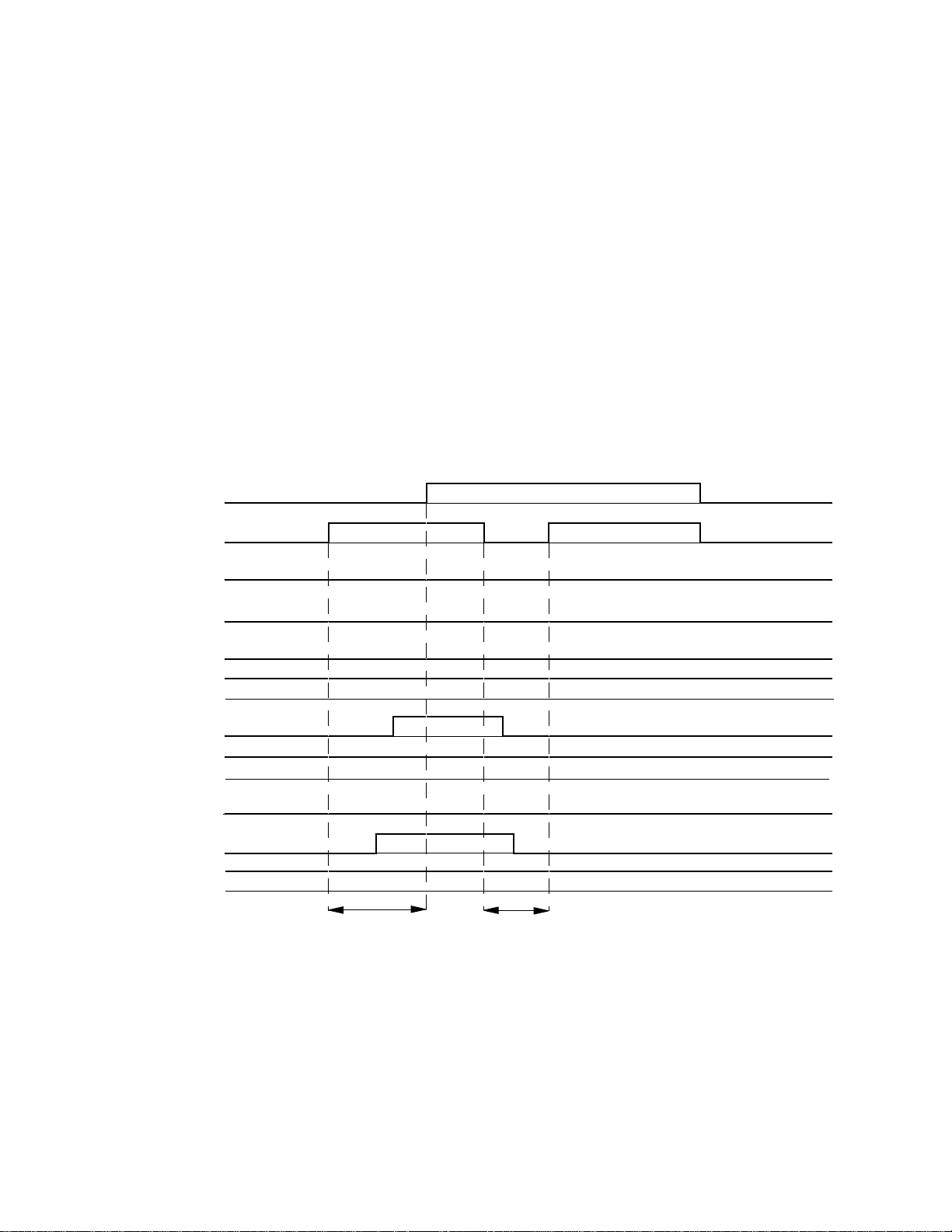
Initialized operation (without any magazine pack).
After microcomputer reset starting moves an elevator position to the position of DISC1, and carries out initial operation.
1, Elevator motor control terminal ELV+ (3PIN) is set to L,
ELV- (4PIN) is set to H, and an elevator position is moved
downward.
2, UP SW (SW2 for IC301, 26PIN) checks H (SW2 is OFF
position).
ELV +
(IC301 3pin)
ELV (IC301 4pin)
LOAD +
(IC301 1pin)
L
H
L
3, Elevator motor control terminal ELV+ (3PIN) is set to H,
ELV- (4PIN) is set to L, and an elevator position is moved
upward.
4, UP SW (SW2 for IC301, 26PIN) checks L (SW2 is ON po-
sition).
5, After checking DISCC (31PIN), and carries out DISC1 po-
sition detection (PHT1).
6, ELV+ (3PIN) and ELV- (4PIN) are set to H, and elevator
operation is made to STOP.
Timing chart 1
L
H
L
H
L
L
LOAD (IC301 2pin)
LOAD OUT SW
(SW1 , IC301 28pin)
CLAMP SW
(SW302 , IC301 29pin)
UP SW
(SW2 , IC301 26pin)
DOWN SW
(SW3 , IC301 27pin)
DISCON
(IC301 33pin)
DISC.C
(PHT1 , IC301 31pin)
MAG SW
(SW5, IC301 64pin)
L
L
H
L
H
L
L
H
ELEVATOR
DOWN
H
H
L
L
ELEVATOR
UP
8
KDV-C810/C820/C830
TIMING CHART OF MECHANISM OPERATION
/C840/C860
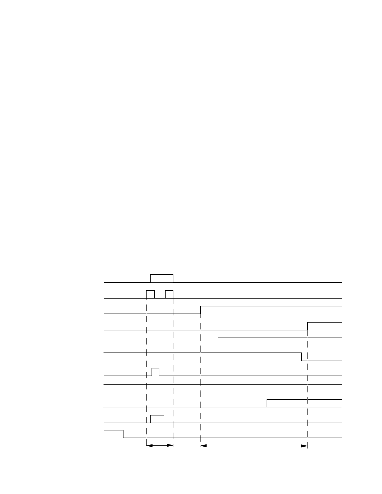
Magazine pack in (for disc clamp about DISC1).
Detection of insertion of a magazine pack checks whether
an elevator position is in DISC1 (top position).Basic operation is the same as initial operation. Then, DISC1 is pulled
out from a magazine pack and a disc clamp is carried out.
1, Detection for MAGSW (SW5 for IC301, 64PIN) checks L.
2, An elevator position and initial operation is performed.
3, LOAD+ (IC301, 1PIN) is set to H, LOAD- (IC301, 2PIN) is
set to L, and DISC1 tray is pulled out from a magazine
pack.
4,LOADING MOTOR (VM3) is driven until CLAMP SW
(SW302) is set to L.
5, LOAD+ (IC301, 1PIN) and LOAD- (IC301, 2PIN) are set
to H, and loading operation is made to STOP.
Operation for disc clamp after playback
A disc detection sensor (D1) performs the focus search, after
that detection (DISCON H) for disc existence, and it goes
into playback mode.
1, Laser ON.
2, Focus search ON.
3, Focus error detection. (f or disc surf ace and recorded la yer)
When FE of a recorded side is detected twice, it distinguishes from the two layer disk of DVDs. CD and DVD is
distinguished by the time lag of FE detected from recorded
side and disc surface. When distinguished from CD, the
reflective level of a disc is detected and CD/CD-RW is dis-
tinguished.
4, Focus, Tracking servo ON.
5, Automatic adjustment of circuit.
Focus, Tracking offset, Focus, Tracking loop gain, Focus,
Tracking balance and RF gain.
6, TOC information read-out.
7, Playback start.
ELV +
(IC301 3pin)
ELV (IC301 4pin)
LOAD +
(IC301 1pin)
LOAD (IC301 2pin)
LOAD OUT SW
(SW1 , IC301 28pin)
CLAMP SW
(SW302 , IC301 29pin)
UP SW
(SW2 , IC301 26pin)
DOWN SW
(SW3 , IC301 27pin)
DISCON
(IC301 33pin)
DISC.C
(PHT1 , IC301 31pin)
MAG SW
(SW5, IC301 64pin)
Timing chart 2
L
H
L
L
H
L
H
H
L
H
L
L
H
LH
H
L
LH
L
H
L
L
H
INITIALIZE
DISC LOADING
9
KDV -C810/C820/C830
/C840/C860
TIMING CHART OF MECHANISM OPERATION
Disc change operation (for operation to out of
DISC1 playback after change to DISC2).
If disc change command is received, the playback disc under
present will be returned to the magazine pack. After that, the
selected disc is pulled out of the magazine pack and disc
tray is carried out.
1, LOAD+ (IC301, 1PIN) is set to L, LOAD- (IC301, 2PIN) is
set to H, and DISC1 tray is returned to a magazine pack.
2, LOADING MOTOR (VM3) is driven until LOAD OUT SW
(SW1 : IC301, 28PIN) is set to L.
3, ELV+ (3PIN) and ELV- (4PIN) are set to H, and elevator
operation is made to STOP.
4, After checking DISCC (31PIN), and carries out DISC2 po-
sition detection (PHT1).
5,Check (PHT1) DISC2 position detection of the DISCC
(31PIN) is carried out.
6, ELV+ (3PIN) and ELV- (4PIN) are set to H, and elevator
operation is made to STOP.
7, LOAD+ (IC301, 1PIN) is set to H, LOAD- (IC301, 2PIN) is
set to L, and DISC2 tray is pulled out from a magazine
pack.
8, LOADING MOTOR (VM3) is driven until CLAMP SW
(SW302 : IC301, 29PIN) is set to L.
9, LOAD+ (IC301, 1PIN) and LOAD- (IC301, 2PIN) are set to
H, and loading operation is made to STOP.
ELV +
(IC301 3pin)
ELV (IC301 4pin)
LOAD +
(IC301 1pin)
LOAD (IC301 2pin)
LOAD OUT SW
(SW1 , IC301 28pin)
CLAMP SW
(SW302 , IC301 29pin)
UP SW
(SW2 , IC301 26pin)
DOWN SW
(SW3 , IC301 27pin)
DISCON
(IC301 33pin)
DISC.C
(PHT1 , IC301 31pin)
MAG SW
(SW5, IC301 64pin)
L
HL H
H
L
L
H
H
L
H
L
Timing chart 3
L
H
L
L
H
L
H
L
L
H
H
H
H
L
H
L
10
DISC UNLOADING
ELEVATOR
DOWN
DISC LOADING
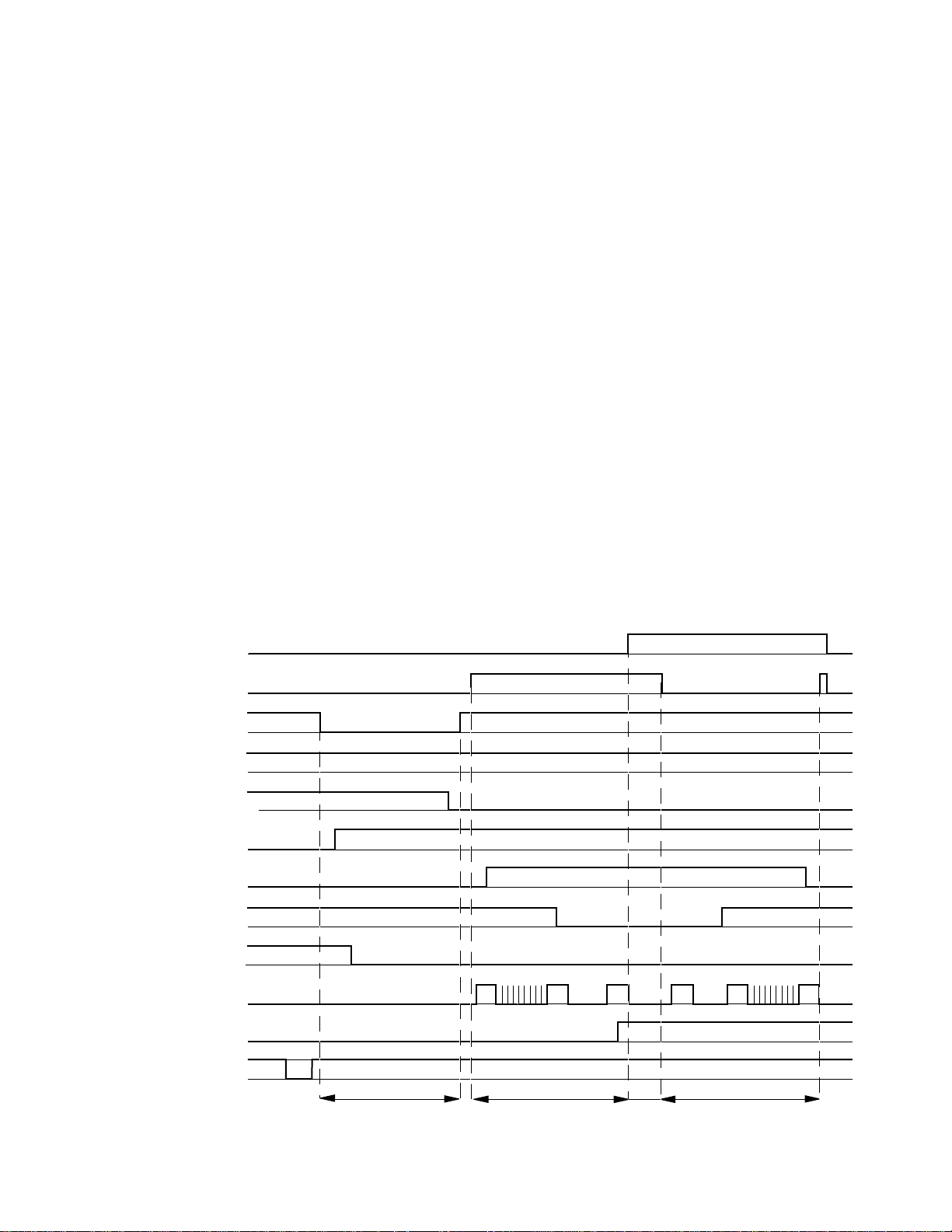
TIMING CHART OF MECHANISM OPERATION
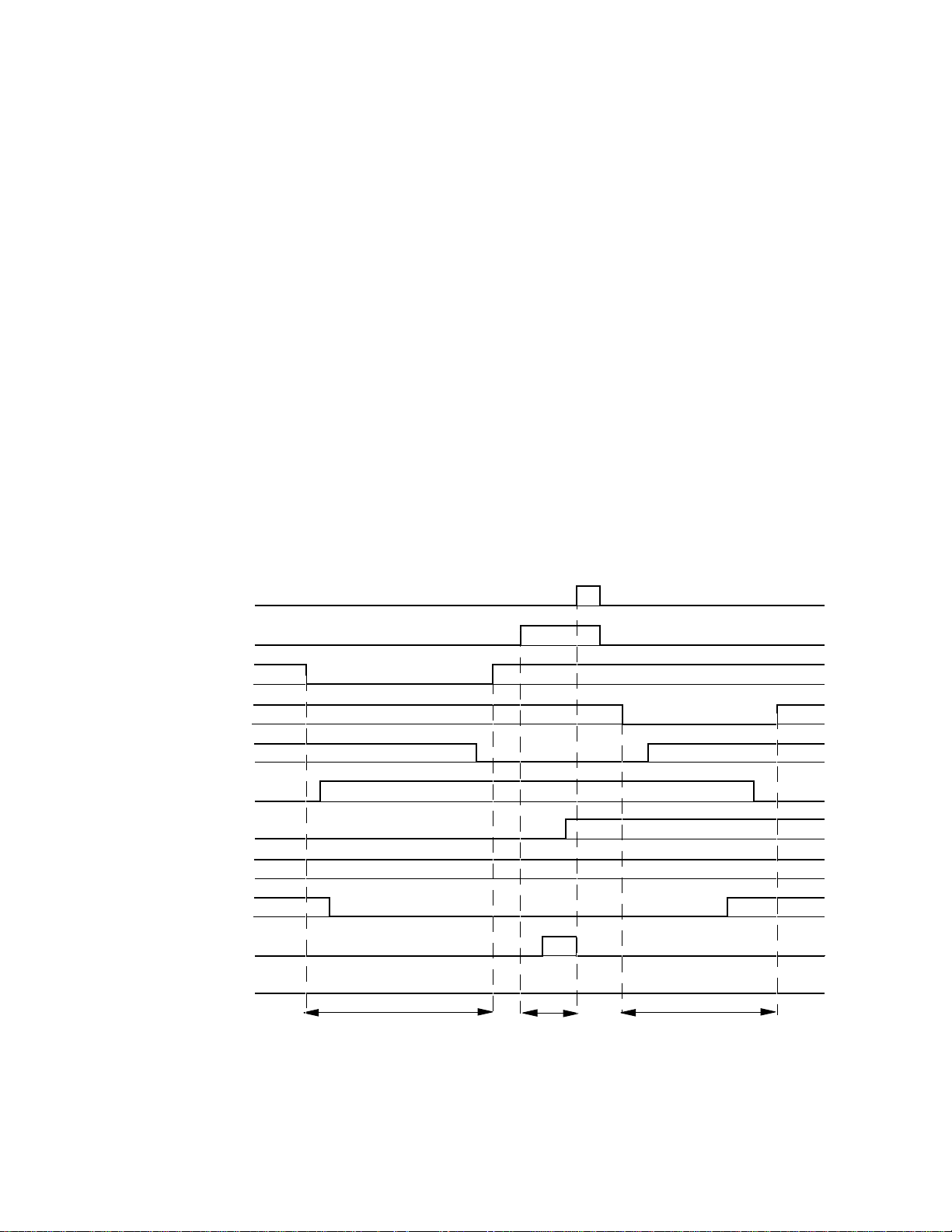
Magazine ejection operation (for operation to DISC1 playback after magazine pack eject)
If the input of EJECT SW (SW301) is detected, the playback
disc under present will be returned to a magazine pack, an
elevator mechanism part will be moved to an eject position
(most below position), and a magazine pack will be discharged. After that, an elevator mechanism part is moved to
DISC1.
1, LOAD+ (IC301 and 1PIN) is set to L, LOAD- (IC301, 2PIN)
is set to H, and DISC1 tray is returned to a magazine pack.
2, LOADING MOTOR (VM3) is driven until LOAD OUT SW
(SW1 : IC301, 28PIN) is set to L.
3, LOAD+ (IC301, 1PIN) and LOAD- (IC301, 2PIN) are set to
H, and loading operation is made to STOP.
4, Elevator motor control terminal ELV+ (3PIN) is set to L,
ELV- (4PIN) is set to H, and an elevator mechanism is
moved downward.
KDV-C810/C820/C830
/C840/C860
5, ELEV ATOR MOT OR (VM4) is driven until DO WN SW (SW3)
is set to L.
6, EJECT position detection of the DISCC (31PIN) is carried
out. H->L (it checks twice).
7, ELV+ (3PIN) and ELV- (4PIN) are set to H, and elevator
operation is made to STOP.
8, After 2 seconds of magazine pack eject, elevator motor
control terminal ELV+ (3PIN) is set to H, ELV- (4PIN) is set
to L, and an elevator mechanism part is moved upward.
9, UP SW (SW2 for IC301, 26PIN) checks L.
10, After chec king DISCC (31PIN) (PHT1), DISC1 position
detection is carried out.
11,ELV+ (3PIN) and ELV- (4PIN) are set to H, and elevator
operation is made to STOP.
ELV +
(IC301 3pin)
ELV (IC301 4pin)
LOAD +
(IC301 1pin)
LOAD (IC301 2pin)
LOAD OUT SW
(SW1 , IC301 28pin)
CLAMP SW
(SW302 , IC301 29pin)
UP SW
(SW2 , IC301 26pin)
DOWN SW
(SW3 , IC301 27pin)
DISCON
(IC301 33pin)
DISC.C
(PHT1 , IC301 31pin)
MAG SW
(SW5, IC301 64pin)
EJECT SW
(SW5, IC301 45pin)
H
L
H
H
HL H
Timing chart 4
L
H
L
H
L
H
H
L
Disc
1
L
L
H
L
H
Disc 2 to 9 Disc 2 to 9
Disc
10
L
L
H
Disc
10
H
L
H
L
L
Disc
1
DISC UNLOADING
ELEVATOR
DOWN
EJECT
POSITION
ELEVATOR
UP
11
 Loading...