

Kenwood KD-CX-493, KD-CW-5644-UY, KD-CMP-6043-U, KD-CMP-442-U, KD-CW-5544-U Service Manual
CD RECEIVER
KDC-MP442U/MP6043U
KDC-W5544U/W5644UY
KDC-X493
SERVICE MANUAL
© 2009-1 PRINTED IN JA PAN
B53-0697-00 (N) 429
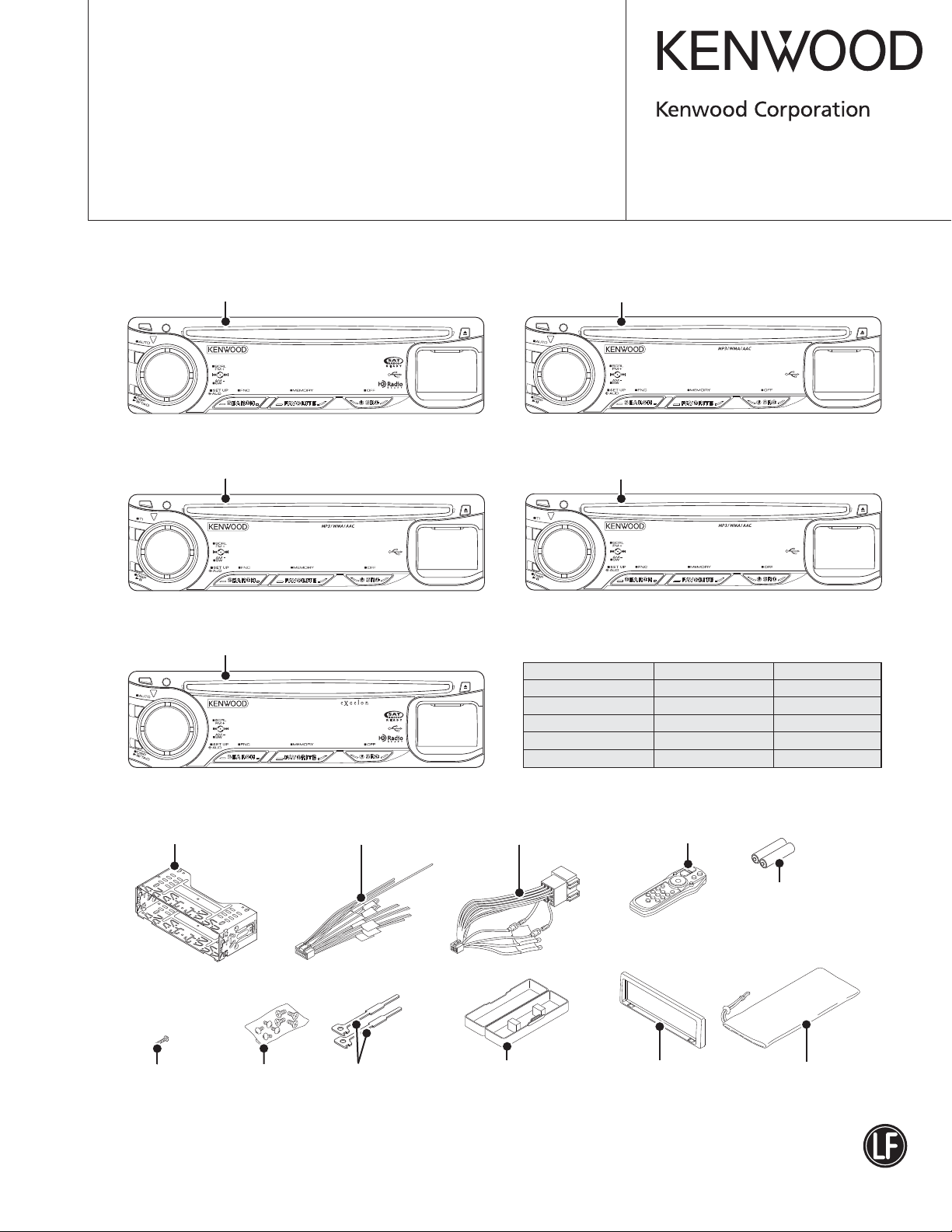
Panel assy
KDC-MP442U (A64-4719-02)
Panel assy
KDC-W5544U (A64-4720-02)
Panel assy
KDC-X493 (A64-4718-02)
KDC-MP442U
KDC-W5544U
KDC-X493
Panel assy
KDC-MP6043U (A64-4722-02)
KDC-MP6043U
Panel assy
KDC-W5644UY (A64-4721-02)
KDC-W5644U
TDF SPARE-PANEL
MAIN UNIT NAME TDF PARTS No. TDF NAME
KDC-MP442U Y33-3060-10 TDF-94DX
KDC-MP6043U Y33-3060-21 TDF-MP6043U
KDC-W5544U Y33-3062-71 TDF-W5544U
KDC-W5644UY Y33-3062-71 TDF-W5544U
KDC-X493 Y33-3060-11 TDF-MP94D
Mounting hardware assy
(J22-0789-03)
* Screw (4x16)
(N84-4016-48)
* Depends on the model. Refer to the parts list.
* Screw set
(N99-1757-15)
* DC cord
(E30-6428-05)
Lever
(D10-7049-04) x2
* DC cord
(E30-6671-05)
* Plastic cabinet assy
(A02-2755-23)
This product complies with the
* Remote controller assy (RC-547)
(A70-2085-15)
Battery
(Not supplied)
* Escutcheon
(B07-xxxx-xx)
This product uses Lead Free solder.
RoHS directive for the European market.
* Carrying case
(W01-xxxx-xx)
2
(X92-6360-00)
USB u-COM
iPod
AUTHENTICATION
3.3V
5V
LEVEL SHIFT
ROM
CORRECTION
ELECTRIC UNIT (X34- )
∗
DME1
CD MECHA
X92-6320-00
(W/O USB MODEL)
or
X92-6360-00
(USB MODEL ONLY)
A480 or A481
FRONT-END
E2PROM
FST
MPX for RDS
∗
J400
LX BUS
AM+B
A8V
SW5V
BACK
UP
SWITCH UNIT (X16- )
SERVO
BU5V
USB5V
∗
J4
USB CN AUX
∗
RESET
IC
S3 S1
RESET
SW
J3
IC500
RDS
DECODER
IC301
R520
PAN
DET
GND
∗
IC241
MEMORY
BU5V
ROTARY
ENCODER
∗
SW5V
IC302
3
25
CN
Q5,21
SW5V
IC2
REMOTE
IC240
DSP
IC260
E-VOL
I2CI2C
A8V
LPF
ED1
AC IN
AC OUT
WININ
MUTE
DC ERRDC DET
MUTE
∗
A600
BLUETOOTH
MODULE
ILLUMI+B
PAN5V
R74,
75
1/2W
Rx2
FL
(with DRIVER)
14-SEG 13-DIGIT
MATRIX
CD
MD
FM/AM
CH (ISO IN)
AUX (ISO IN)
SYSTEM u-COM
∗
IC600
KEY ILLUMI KEY
(LED)
FDC
DSP5V
A8V
A4V
PRE+B
STBY
PRE MUTE
2
∗
P-IC MUTE
J520
J1
CN1
MIC
BT3.3V
Q441,461
SW MUTE
IC303
MUTE
DRIVER
RST
PAN5V
SERVO
USB5V
FDC
BT3.3V BT3.3V
ILLUMI+B
PRE+B
DSP5V
BU5V
BU5V
SW5V
A8V
AM+B
∗
IC150
HI-SIDE
SW
∗
IC601
Q440,442,
450,451,
460,462
PRE
MUTE
IC200
POWER IC
OFFSET
Q90
BU DET
Q93
SURGE DET
∗
D130
TEL MUTE
Q92
ACC DET
∗
Q130
DIMMER
∗
Q114,115
ANT-CON
Q110-113
Q520
PAN5V
Q30,31
SW5V
Q480,481
AM+B
IC70
D5V
P-CON
Q32,33
BU5V
IC10
A8V
Q40-43
SERVO
Q50-53
ILLUMI+B
∗
Q81-83
4V-PRE
+B
∗
Q20-23
DSP5V
∗
J420
∗
WH160
∗
∗
PRE OUT
(SW)
J1
SP OUT (FL)
SP OUT (FR)
SP OUT (RL)
SP OUT (RR)
BACK UP
∗
ACC
∗
∗
P. CON
WIRED
REMOTE
PRE OUT
(FRONT)
PRE OUT
(REAR)
LINE MUTE
DIMMER
ANT CON
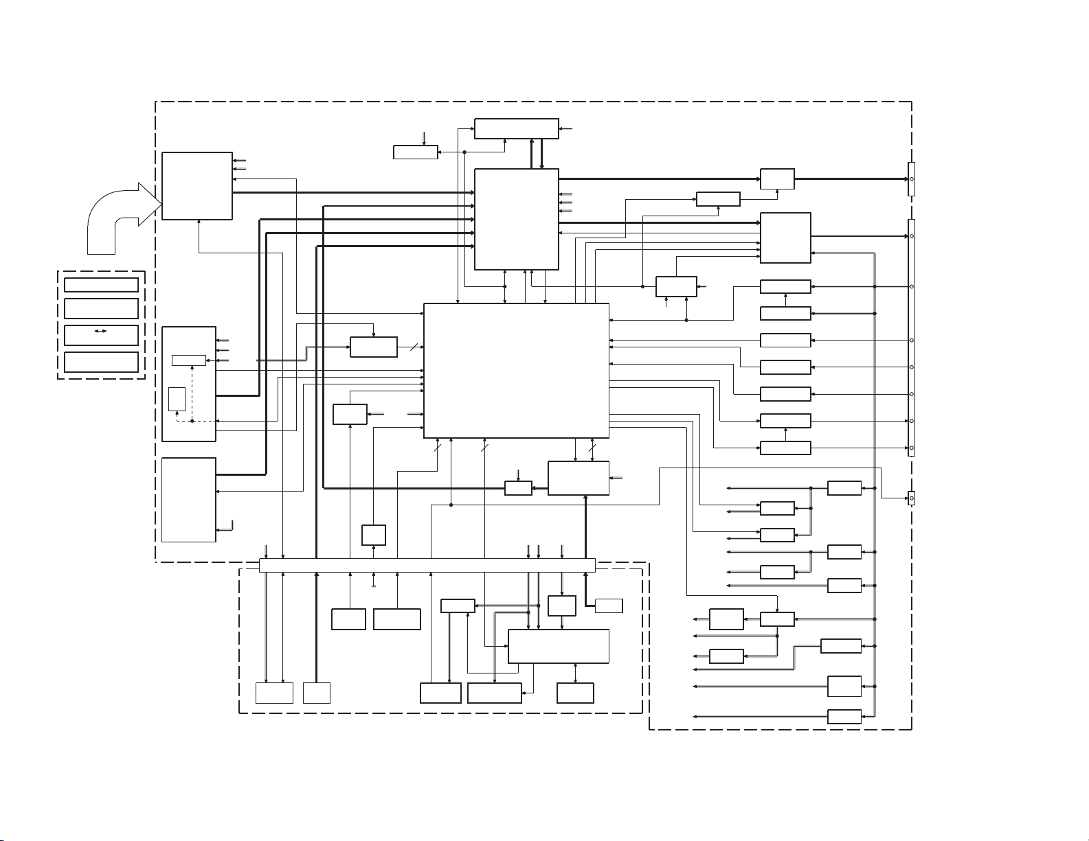
BLOCK DIAGRAM
/W5544U/W5644UY/X493
KDC-MP442U/MP6043U
DPU1
ACB
EF
FO COIL
TR COIL
DM1
SPINDLE
MOTOR
DM2
LOADING &
SLED
MOTOR
CD PLAYER UNIT (X32-6260-00)
IC2
SIGNAL A/B/C/E/F
Q7
APC
IC3
FOO
TRO
MOTOR
DRIVER
DMO
FMO
PD
LD
VREF
FOO
TRO
DMO
FMO
X3
CLOCK
16.934MHz
RF AMP
SERVO
PROCESSOR
MP3 DECODER
WMA DECODER
AAC DECODER
1Mbit SRAM
Q3
SW
+
+
+
+
+
BU1.5V
SW1.5V
S
DVSS
D
G
D3.3V
AVSS
CD REQ
SRAMSTB
BSIF ST REQ
BSIF GATE
BSIF DATA
BSIF BCK
BSIF LRCK
A3.3VLORO
SW3.3V
SO
SI
BUCK
CCE
RST
Z DET
IC4
iPod
AUTHENTICATION
IC1
CD SO
CD CLK
DSP REQ
CE
CD SRAMSTB
CD RST
ZDET IN
BSIF ST REQ
BSIF GATE
BSIF DATA
BSIF BCK
BSIF LRCK
CD DRIVE MUTE
IPOD SDA
IPOD SCL
IC9
9.000MHzX132.768kHz
PON
SW3.3V
REG
CLOCK
MECHANISM
u-COM
DVSS
DVCC3A
Q5
SW
X2
PWE
CLOCK
CD LOE LIM SW
RVIN1/RVIN2
DVCC3B
BU3.3V
BU1.5V
DATA SCD SI
REQ A
MSTOP
MRST
DATA M
REQ M
CLK
CD MUTE
USB D+
USB D-
USB OC
USB VBUS SW
IC7
BU3.3 /
BU1.5V
REG
IC5
LEVEL
SHIFT
IC6
LEVEL
SHIFT
MOTHER
BOARD
(X34- )
SO
CCE
MSTOP
MRST
SI
REQ
BUCK
MUTE L/R
USB+
USBVBUS OC
VBUS SW
Lch
Rch
BU5V
Q9
DGND
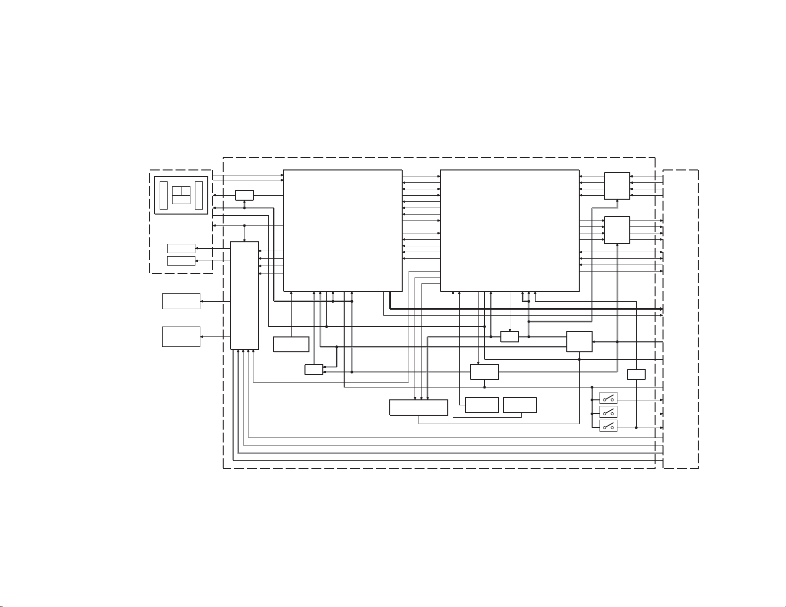
BLOCK DIAGRAM
INV
S1
S2
S3
AGND
LOS SW
12EJE SW
LOE SW
LO/EJ
MOTOR
S7.5V
S.GND
/W5544U/W5644UY/X493
KDC-MP442U/MP6043U
3
KDC-MP442U/MP6043U
/W5544U/W5644UY/X493
COMPONENTS DESCRIPTION
ELECTRIC UNIT (X34-630x-xx)
●
Ref. No. Application / Function Operation / Condition / Compatibility
IC10 Audio 8V REF / Power Supply Outputs 1.27V.
IC70 Digital AVR for Panel & USB Switching regulator for USB&VBUS and FDC (5V).
IC150 Power Control SW USB power control switch with over current detection and protection.
IC200 Power IC Amplifi es front L/R and rear L/R.
IC241 E2P Memory DSP setting memory.
Selects analog source & full source volume. Analog source: AM/FM, CH, AUX.
IC260 Source Selector & E-VOL
IC301 System μ-COM Reset Control Outputs Lo (system μ-COM reset) when detection voltage goes below 3.6V.
IC302 System μ-COM
IC303 Mute Logic Controls logic for muting.
IC500 RDS & RBDS Decoder
Q10~12 Audio 8V AVR During active time, POWER is ON.
Q30,31 SW5V During active time, POWER is ON.
Q32,33 BU5V AVR During active time, POWER is ON.
Q40~43 Servo AVR During active time, POWER is ON.
Q50~53 ILLUMI AVR During active time, POWER is ON.
Q80 Overcurrent Protection When the base goes Hi, 4V preout AVR is OFF.
Q81~83 4V Preout AVR During active time, POWER is ON.
Q90 BU DET SW Detects the backup voltage. If the backup is detected, it is ON.
Q92 ACC DET SW Detects ACC voltage. If ACC is detected, it is ON.
Q93 Surge DET SW Detects over-input voltage. If surge is detected, it is ON.
Q110~113 Power Cntrol Output
Q114,115 Power ANT SW During active time, tuner source is active.
Q130 Small Lamp DET SW Detects small lamp. If small lamp is detected, it in ON.
Q440 Preout Mute SW Non-fader Lch
Q441 Preout Mute Driver (Non-fader) When this transistor is ON, mute is active.
Q442 Preout Mute SW Non-fader Rch
Q450 Preout Mute SW Front Lch
Q451 Preout Mute SW Front Rch
Q460 Preout Mute SW Rear Lch
Q461 Preout Mute Driver (F/R) When this transistor is ON, mute is active.
Q462 Preout Mute SW Rear Rch
Q480,481 AM+B SW During active time, AM source is active.
Q520 PAN5V SW When the base goes Lo, PAN5V is ON.
Digital source is selected by CD mecha. (CD/USB)
Speaker-out “DC-offset” detection and protection. (This function consists of
IC260 and IC200)
System control including power management, panel control, AM/FM/CH/SOC
control, external control and etc.
When the base of Q110 goes Hi, power control output is ON. During active time,
audio source is active.
SWITCH UNIT (X16-6500-10)
●
Ref. No. Application / Function Operation / Condition / Compatibility
IC2 Remote Controller Remote control receiver.
Q5 PAN5V When the base goes Hi, PAN5V is supplied for IC2.
Q20 Key Scan Timing Adjustment When the base goes Hi, key scan starts.
4
KDC-MP442U/MP6043U
/W5544U/W5644UY/X493
COMPONENTS DESCRIPTION
Ref. No. Application / Function Operation / Condition / Compatibility
Q21 PAN5V When the base of Q5 goes Hi, PAN5V is supplied for IC2.
Q22 Grid Reversing Driver When the base goes Hi, GRID1 is ON.
Q23 Grid Reversing Driver When the base goes Hi, GRID2 is ON.
Q24 Grid Reversing Driver When the base goes Hi, GRID3 is ON.
Q51 Left Sub-ILLUMI Controller When the base goes Hi, left sub-illumination is ON.
Q52 Center 3-key ILLUMI Controller When the base goes Hi, center 3-key illuminations are ON.
Q53 Right Sub-ILLUMI Controller When the base goes Hi, right sub-illuminations are ON.
CD PLAYER UNIT (X32-6260-00)
●
Ref. No. Application / Function Operation / Condition / Compatibility
IC1 Mechanism μ-COM
IC2 Servo DSP with Built-in Audio DAC
IC3 4ch BTL Driver
IC4 iPod Authentication
IC5 3.3V→5.0V Level Shift Converts communication signal from 3.3V to 5.0V.
IC6 5.0V→3.3V Level Shift Converts communication signal from 5.0V to 3.3V.
IC7 BU1.5V / BU3.3V Regulator
IC8 E2PROM
IC9 A3.3V Regulator Power supply for digital, analog and audio line.
Q3 D1.5V Output
Q5 B.3.3V Output
Q6 Control signal Inverter Controls Q5.
Q7 APC (Auto Power Control) Laser diode driver.
Q9 Control signal Inverter
D1 Laser Diode Protection
D2,3 Countermeasure against Static Electricity
Controls DSP and peripheral circuit.
USB host controller. (Compliant with Universal Serial Bus Specifi cation Rev2.0)
Built-in MP3·WMA·AAC decoder.
Built-in 1M-bit-SRAM.
Driver for focusing & tracking coil, driver for sled & spindle motor, and operation
for disc loading & ejection.
Connection authentication for iPod.
MFI341S2162: iPhone-compliant.
Power supply for digital back-up.
Power supply for mechanism μ-COM.
Memory for ROM correction.
Countermeasure for software malfunction.
The output voltage in which the power supply that diverges from the BU1.5V line
is turned on and off is used as D1.5V.
The output voltage in which the power supply that diverges from the BU3.3V line
is turned on and off is used as D3.3V.
Because the detection logic of LOE/LIM_SW is different in the mechanism
μ-COM and the system μ-COM, the logic to the mechanism μ-COM side is
reversed.
Prevents reverse bias which is applied to laser.
Laser destruction prevention.
The potential difference between DGND and AGND is absorbed, and the
malfunction by static electricity is prevented.
5
KDC-MP442U/MP6043U
/W5544U/W5644UY/X493
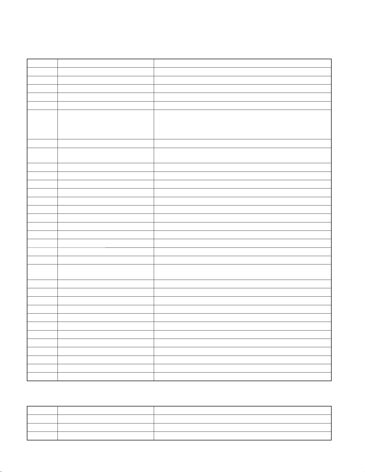
MICROCOMPUTER’S TERMINAL DESCRIPTION
SYSTEM μ-COM: IC302 on X34- (ELECTRIC UNIT)
●
Pin No. Pin Name I/O Application
1 REMO I
2 LX REQ M O Communication request to slave unit
3 B SYS DATA O Serial output to Bolero
4 B MECHA DATA I Serial input from Bolero
5 B MECHA CLK I Serial clock input from Bolero
6 BYTE -
7 CNVSS -
8 XCIN - Sub clock 32.768kHz
9 XCOUT - Sub clock 32.768kHz
10 RESET -
11 XOUT - Main clock 12.00MHz
12 VSS -
13 XIN - Main clock 12.00MHz
14 VCC1 -
15 NMI -
16 LX REQ S I Communication request from slave unit
17 RDS CLK I RDS decoder clock input (Terminal for European model)
18 PANEL DET
19 PON AM I/O AM power supply control AM operated: H, AM not operated: Hi-Z
20 TUN IFC OUT I Front-end IFC-OUT input H: Station found, L: No station
21 RDS AFS M I/O Noise detection time constant SW (Terminal for European model)
22 RDS QUAL I/O RDS decoder qualifi cation input (Terminal for European model)
23 RDS DATA I RDS decoder data input (Terminal for European model)
24 V SYNC - Not used Output L fi xed
25 NC - Not used Output L fi xed
26 PWIC BEEP O Beep output 2kHz/1kHz (Model with Bluetooth)
27 TUN SCL I/O Front-end I2C clock input/output MAX 400kHz
28 TUN SDA I/O Front-end I2C data input/output
29 VFD DATA I/O VFD data input/output
30 ROTARY CW I VOL key detection (Clockwise)
31 VFD CLK O VFD clock output 125kHz
32 VFD RST
33 BT SYS DATA O Data output to Bluetooth
34 BT BT DATA I Data input from Bluetooth
35,36 NC - Not used Output L fi xed
37 PON D5V I/O SW-REG control H: ON, Hi-Z: OFF
38 NC - Not used Output L fi xed
39 ROMCOR DET I E2PROM writing request H: Writing
40 PDN O Simple DSP power down H: ON, L: OFF
41 DFZ MUTE I Mute request from simple DSP L: Mute request
External remote control input and panel remote
control input
I Panel connector detached/attached detection H: Panel detached, L: Panel attached
O VFD reset
Truth Value
Table
Processing / Operation / Description
Detects pulse width
TDF: 15-pulse/360°, 2-click/1-pulse
H: Reset released, L: Reset
Momentary power-down or panel detached
or 11 minutes after ACC OFF: L
6
KDC-MP442U/MP6043U
/W5544U/W5644UY/X493
MICROCOMPUTER’S TERMINAL DESCRIPTION
Pin No. Pin Name I/O Application
42 ROTARY CCW I VOL key detection (Counterclockwise)
43 NC - Not used Output L fi xed
44 VFD CS O VFD control request H: Possible to transfer VFD data
45 BT RST O Bluetooth module reset L: Normal, H: Bluetooth reset
46 VFD INT I VFD-INT input
47 NC - Not used Output L fi xed
48 PON PANEL I/O Panel 5V power supply control
49 PON O Power supply control H: Power supply ON, L: Power supply OFF
50 CD DISC12 SW I 12cm disc detection
51 CD LOS SW I CD loading detection
52 MECHA STOP O SOC (System On Chip) stop H: Normal, L: SOC stopped
52 CD PON O CD mechanism power supply control H: ON, L: OFF
53 CD MUTE
54 S MECHA REQ
55 MECHA RST
56 SRAMSTBY O Decoder SRAM standby control H: SRAM standby
56 NC - Not used Output L fi xed
CD LOE LIM
57
SW
58 S SYS REQ O
58 MDSP CE O Mechanism chip enable
59 PON ILL O Key illumination power supply control H: Power supply ON, L: Power supply OFF
60 VCC2 -
61 DRV MUTE O CD motor driver mute output
62 VSS -
63 TYPE 1 I Destination SW
64 TYPE 2 I Destination SW
65 NC - Not used Output L fi xed
66 CD LOEJ I/O CD motor control
67 CD MOTOR O CD motor control
68~70 NC - Not used Output L fi xed
71 ILLUMI DET I Dimmer illumination detection L: ON, H: OFF
72 ACC DET I ACC power supply detection ACC found: L, No ACC: H
73 BU DET I Momentary power-down detection BU found: L, Momentary power down: H
74 ANT CON O Power antenna control Tuner ON: H
75 PCON O External power amplifi er control
76 PWIC SVR O Power IC SVR discharge circuit control H: ON, L: OFF
77 PWIC MUTE O Power IC mute control
78 PWIC STBY O Power IC standby control
79 LINE MUTE I Line mute detection TEL mute: Below 1V, NAVI mute: Over 2.5V
I CD Mute request L: Mute request, H: Normal
Communication request from mechanism to system
I
μ-COM
O SOC (System On Chip) reset H: Normal, L: Reset
I CD detection (Chucking SW) H: Loading completed, L: No disc
Communication request from system μ-COM to
mechanism
Truth Value
Table
q
q
Processing / Operation / Description
Detects pulse width
TDF: 15-pulse/360°, 2-click/1-pulse
ON (For 11 minutes after ACC OFF): L
Momentary power-down or panel detached
or 11 minutes after ACC OFF: Hi-Z
Refer to the truth value table
Refer to the truth value table
7
KDC-MP442U/MP6043U
/W5544U/W5644UY/X493
MICROCOMPUTER’S TERMINAL DESCRIPTION
Pin No. Pin Name I/O Application
80 ST DC DET I Wrong connection detection
81 E2P SDA I/O E2PROM I2C data input/output
82 E2P SCL I/O E2PROM I2C clock input/output
83 DC DET I DC offset detection
84 MUTE AFS
85 MUTE 0
86 MUTE 1
87 MUTE 2
88 MUTE PRE FR
89 MUTE PRE SW
90 RDS NOISE I FM noise detection (Terminal for European model)
91 TUN SMETER I S-meter input
92 LX MUTE I Mute request from slave unit H: Mute ON, L: Mute OFF
93 LX CON O Start-up request to slave unit H: Slave unit ON , L: Slave unit OFF
94 AVSS -
95 LX RST O Forced reset to slave unit H: Reset, L: Normal
96 VREF -
97 AVCC -
98 LX DATA S I Data from slave unit
99 LX DATA M O Data to slave unit
100 LX CLK I/O LX-BUS clock
I/O AFS mute L: Mute ON, Hi-Z: Mute OFF
O E-VOL Front mute L: ON, H: OFF
O E-VOL Rear mute L: ON, H: OFF
O E-VOL Sub Woofer mute L: ON, H: OFF
O PRE-OUT mute Front/Rear
PRE-OUT mute SW (Sub Woofer)
O
* For both PRE-OUT Rear selected and SW selected.
Truth Value
Table
Processing / Operation / Description
Lo when mute is Lo (CD played).
Momentary power-down: L
H fi xed only when Dual Zone is ON.
L: Mute, H: Mute OFF
Lo when mute is Lo (CD played).
Momentary power-down: L
• Truth value table
CD motor control
q
Stop L L
Load H L
Eject H H
Brake H Hi-z
8
CD motor CD loading/eject
KDC-MP442U/MP6043U
/W5544U/W5644UY/X493
TEST MODE
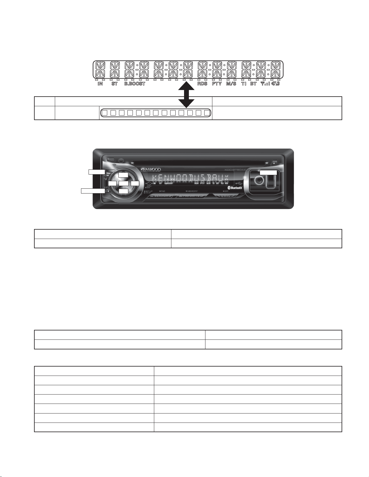
Display description
■
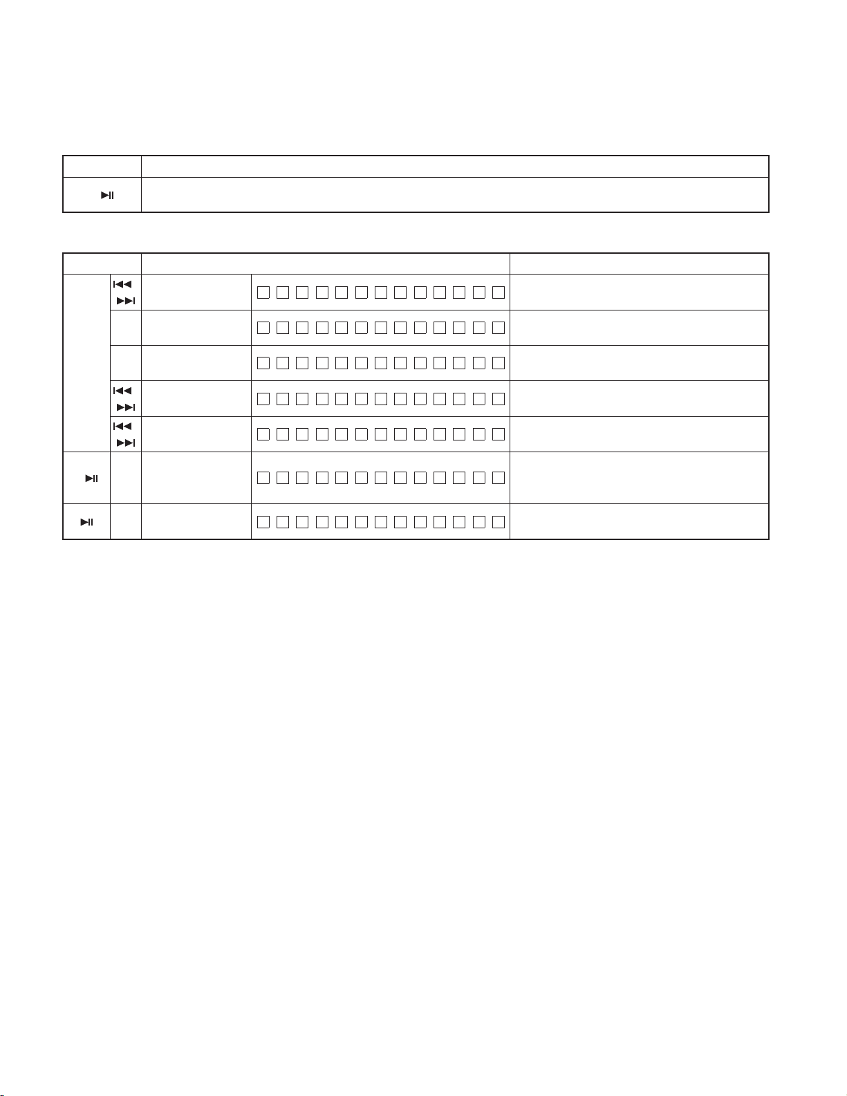
Key Description of display Description
÷÷÷÷÷÷÷
A symbol “■” in the key column indicates that the key should be pressed and held for 1 second or longer.
Key layout
■
TI/AUTO
PLAY/PAUSE
How to enter the test mode
■
Procedure Note
Reset while [SEARCH] and [SRC] keys are being pressed. While “– – – –” is displayed, power can be turned ON.
tt
FM+
AUD
AM–
uu
←
RESET
All lamps blink when it is detected that the sub-clock resonator is disconnected.
When having started up in the test mode, change the LINE MUTE inhibition time from 10 seconds to 1 second.
When operating in the test mode, even if a DC offset error occurs, detection information is not written in the E2PROM.
When operating in the test mode, CD mechanism error log information clear mode, and DC offset error detection information
clear mode, do not perform DEMO mode operations.
Also, do not display DEMO ON/OFF option items in the MENU in STANDBY source in the above modes.
In the test mode the forced disc ejection is prohibited to shorten the period of activation during the test mode transition opera-
tion.
How to clear the test mode
■
Procedure Note
Reset, momentary power down, ACC OFF, POWER OFF, Panel detached. Clearing the test mode
Test mode default condition
■
Description Default values
Source STANDBY
Display Display lights are all turned on.
Volume -10dB (“30” is displayed.)
Bass Boost OFF
CRSC OFF regardless of having/not having the switching function.
AUX ON1
9
KDC-MP442U/MP6043U
/W5544U/W5644UY/X493
TEST MODE
Description Default values
System Q/dB EQ NATURAL (FLAT)
Simple DSP STANDBY (FLAT)
Simple DSP BYPASS (Set up the path that does not go through the DSP)
Beep Goes on (i.e., beeps) when the key is pressed briefl y
Preout Rear
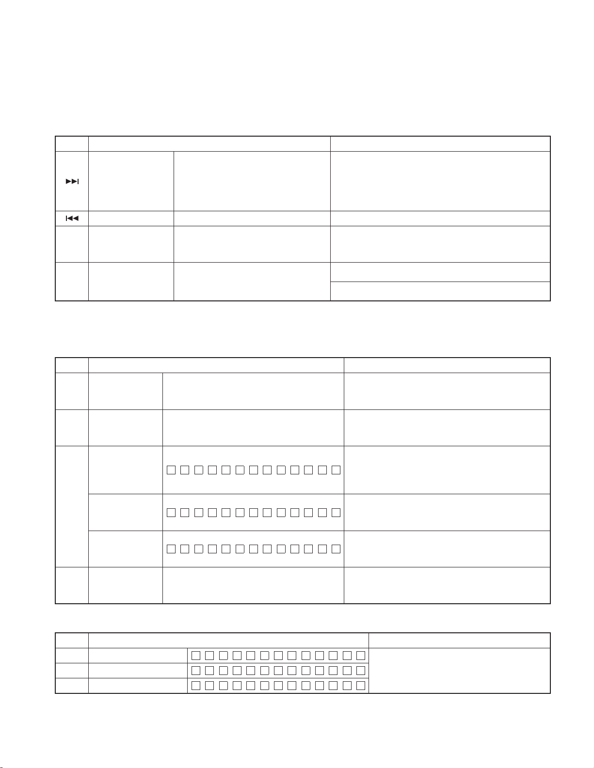
Test mode specifi cation in Standby source
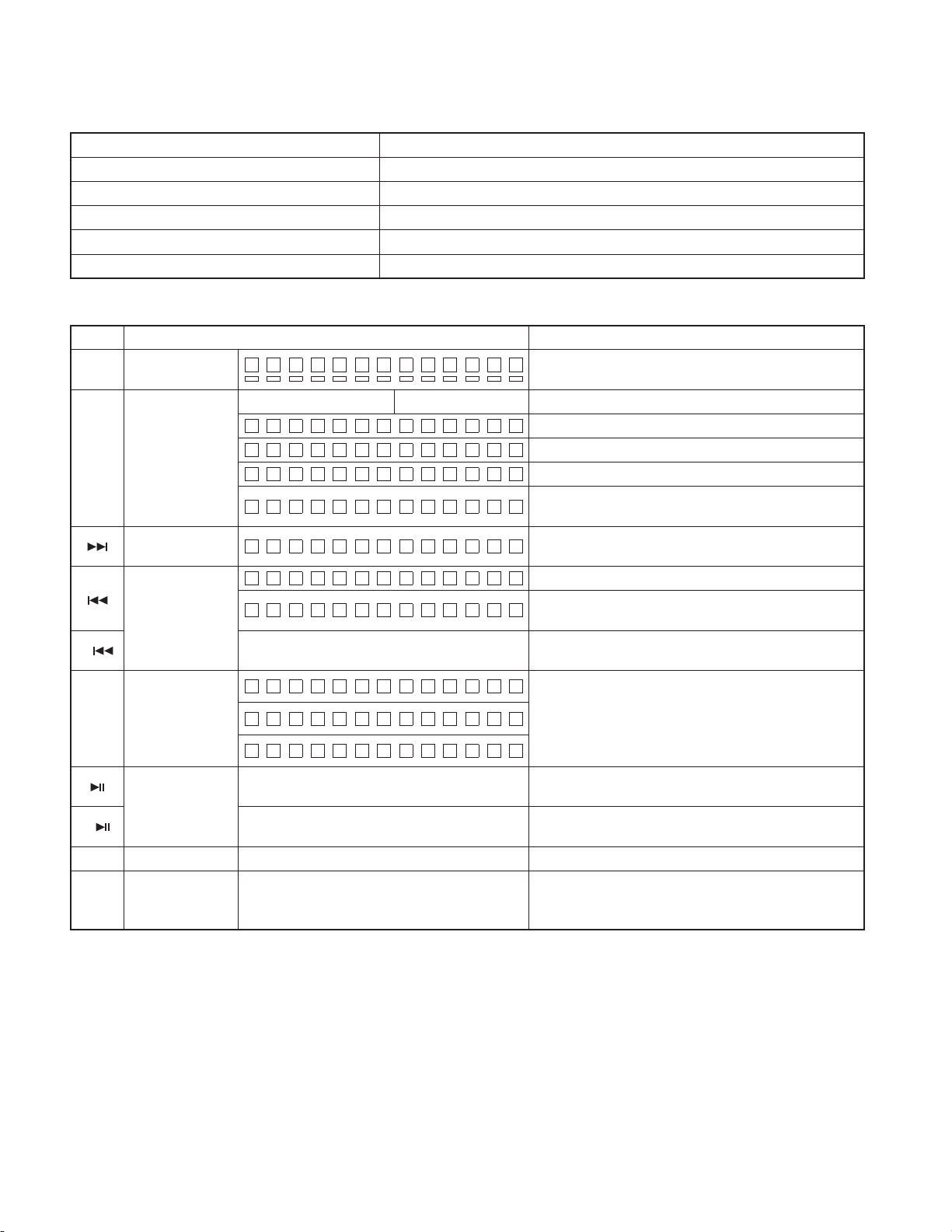
■
Key Description of display Description
Common
FM
■
AUD
■
SEARCH
FAV
All lights ON.
S: R0001M:R0001
ROM correction
version display
Audio data
initialization
Forced Power
OFF information
display
Information display
iPod authentica-
tion IC installation
status display
CD information
display mode
ON/OFF
FNC operation Multi-function operation (Normal operation)
Version & service
information
display
S:ERR M:ERR
S:R––––M:R––––
S:R
AUDIO INIT
POF F – – –
POF F PNL
Move to CD information display mode (sub-mode)
Clear entire CD information
Move to Version and service information display
(Sub-mode)
÷÷÷÷÷÷÷
System μ-com Mecha μ-com
∗∗∗∗
iPod:
iPod:OK
iPod:NG
M:R
∗∗∗∗
All lights ON.
* Red dot lines also go ON.
Figures are ROM correction version number.
In the case when E2PROM is not installed.
In the case when correnction data is not yet written.
In the case when the correction data is incompatible
(Version of data is incompatible)
AUDIO setting value is re-set to the test mode default
value.
No forced power OFF
Forced power OFF by communication error between
system μ-com and panel.
While the forced power OFF data is displayed, press and
hold for 2 seconds to clear the data.
iPod authentication IC installation condition display.
Blank: Checking if the IC is installed
OK: IC is being installed, NG: IC is not yet installed
(Press the key while the display is what is shown in the left
column to return to the normal display)
* Refer to “CD information display mode” for the contents
and operation of the display.
While in CD information display mode, press and hold for
2 seconds or longer to clear all CD information.
* Refer to “Version and service information display” for the
contents and operation of the display.
10
KDC-MP442U/MP6043U
/W5544U/W5644UY/X493
TEST MODE
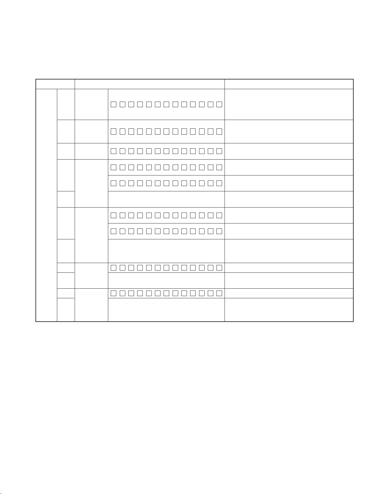
• Version and service information display (Sub-mode)
* When “Version and service information display” is selected, “Destination terminal condition display” will be opened as default
display.
Key Description of display Description
FM
(forward)
↑
↓
AM
(reverse)
■
■
■
■
FAV
FAV
FAV
FAV
Destination
terminal
condition
indication
Development
ID condition
indication
Serial No.
display
Power ON
time display
Disc opera-
tion time dis-
play
Disc EJECT
times display
Panel open/
close times
display
T Y P E 2:1 T Y P E 1:1
C0857WE2 –3.00
SNO 00000000
PONT I M 0 HX X
PONT IM XXXXX
CDT I M 0H XX
CDT IM XXXXX
EJECNT XXXXX
PNCNT XXXXX
“TYPE” indicates system μ-com (IC302) destination,
and shows real-time condition of the destination
terminal.
Development ID – Version (system μ-com: IC302)
Serial No. is displayed (8 digits)
00~50 is displayed for “XX”. When less than 1 hour,
displayed by increments of 10 minutes.
00001~10922 is displayed for “XXXXX”.
MAX 10922 (hours)
When Power ON time is displayed, press and hold for 2
seconds or longer to clear Power ON time.
00~50 is displayed for “XX”. When less than 1 hour,
displayed by increments of 10 minutes.
00001~10922 is displayed for “XXXXX”.
MAX 10922 (hours)
While the disc operation time is displayed, press and
hold for 2 seconds or longer to clear the disc operation
time. (Cleared only for displayed media.)
Disc EJECT times display. MAX 65535 (times)
While disc EJECT times is displayed, press and hold for
2 seconds or longer to clear disc EJECT times.
PANEL open/close times display. MAX 65535 (times)
Press the key for more than 2 seconds while the PANEL
open/close count is displayed and PANEL open/close
count is cleared.
11
KDC-MP442U/MP6043U
/W5544U/W5644UY/X493
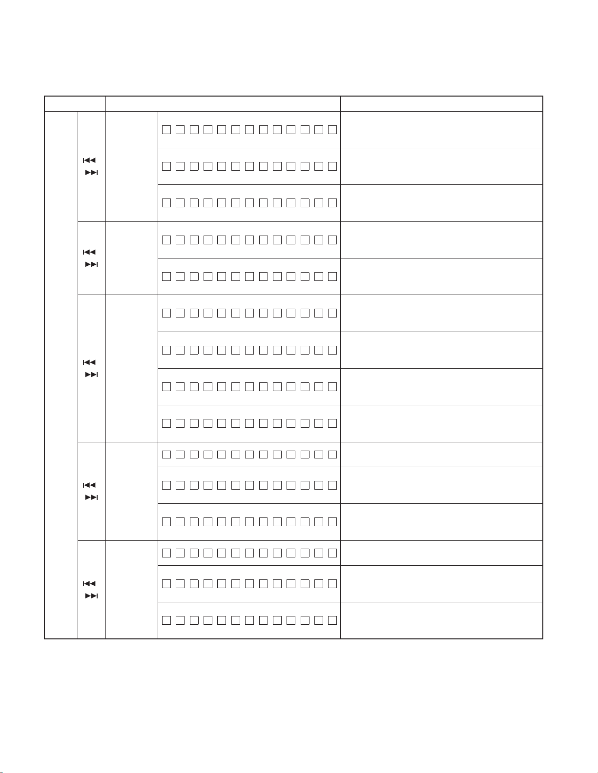
• CD information display mode (Sub-mode)
Key Description of display Description
MECH A ERR 1 :X X
CD mecha-
FM
(forward)
↑
↓
AM
(reverse)
/
nism error
log display
CD Load
/
error
information
display
CD Ejec-
/
tion error
information
display
CD time
code error
/
count data
display
(Missing
counts)
CD time
code error
/
count data
display
(count not
updated)
MECH A ERR 2 :X X
MECH A ERR 3 :X X
LOAD ERR1 :XX
LOAD ERR2 :XX
EJECT ERR1 :XX
EJECT ERR2 :XX
EJECT ERR3 :XX
EJECT ERR4 :XX
CNT LOS E
CDDA :XX
CDROM :X X
CNT STAY
CDDA :XX
CDROM :X X
TEST MODE
Mechanism error log 1 (Latest)
XX: Error number. “– –” is displayed in case there is no
error.
Mechanism error log 2 (Latest)
XX: Error number. “– –” is displayed in case there is no
error.
Mechanism error log 3 (Latest)
XX: Error number. “– –” is displayed in case there is no
error.
Load error switch 1
XX: Number of errors. “– –” is displayed in case there is
no error.
Load error switch 2
XX: Number of errors. “– –” is displayed in case there is
no error.
Ejection error switch 1
XX: Number of errors. “– –” is displayed in case there is
no error.
Ejection error switch 2
XX: Number of errors. “– –” is displayed in case there is
no error.
Ejection error switch 3
XX: Number of errors. “– –” is displayed in case there is
no error.
Ejection error switch 4
XX: Number of errors. “– –” is displayed in case there is
no error.
CD time code error count data (Missing counts) mode
display.
Number of CD-DA count errors
XX: Number of errors. “– –” is displayed in case there is
no error.
CD-ROM (Compressed fi le) number of count errors
XX: Number of errors. “– –” is displayed in case there is
no error.
CD time code error count data (count not updated)
mode display.
Number of CD-DA count errors
XX: Number of errors. “– –” is displayed in case there is
no error.
CD-ROM (Compressed fi le) number of count errors
XX: Number of errors. “– –” is displayed in case there is
no error.
12
KDC-MP442U/MP6043U
/W5544U/W5644UY/X493
TEST MODE
Test mode specifi cations in TUNER source
■
Error is found in front-end (A1), etc. if indications below is displayed while in tuner source.
Status Display Description
Front-end (A48x) E2PROM data
error
Front-end (A48x) communication
error
Destination mismatch
TNE2P NG
TNCON NG
TNTYP NG
• TUNER preset operation
Key Display Description
FAV Preset function
■
F M # 9 8.3 A :4
• K3I forced switching
Every time when [FAV] key is pressed in tuner FM source, switched in the following order: AUTO → Forced WIDE → Forced
MIDDLE → Forced NARROW → AUTO. Default status is AUTO, and displayed as shown below.
Key Display Description
FM1 9 8.1A :
F
FAV K3I Forced switching
M1 9 8.1W
FM1 9 8.1M :
F M 1 9 8.1 N :
Front-end (A48x) E2PROM is still the default
(unspecifi ed) value.
Communication with front-end (A48x) is not
possible.
When destination is mismatch between front-end
(A48x) E2PROM and the product.
Change to 98.3MHz.
AUTO
:
Forced WIDE
Forced MIDDLE
Forced NARROW
• RDS automatic measurement (Only models with RDS)
Add this measurement instead of the visual inspection of PS display that has been used in the production line.
Status Display Description
When the display is what is shown in the left col-
PS data reception
FM1 RDS T E S T:
umn, forcibly turn off.
P-CON returns when the power is turned off/on
(POWER OFF/ON).
13
KDC-MP442U/MP6043U
/W5544U/W5644UY/X493
TEST MODE
• FST adjustment mode
Perform FST soft-mute adjustment.
Key Note
■
Operations in the FST adjustment mode are as follows:
Key Display Description
FM
(UP)
↑
↓
AM
(DOWN)
■
Switch Local Seek ON or OFF by briefl y pressing [TI/AUTO] key when the Local Seek ON/OFF switching is allowed in the band.
After completing the FST adjustment, if you wish to clear the test mode, you can do this using the reset button.
To enter into FST adjustment mode (Press and hold the key for 1 second)
In FM, the frequency changes to 98.3MHz
/ Soft-mute
adjustment
Seek Stop Level
adjustment (Auto)
Seek Stop Level
adjustment (Auto)
/ Seek Stop Level
adjustment (Manual)
/ Seek Stop Level
adjustment (Manual)
Adjustment value
memory
Mode clear
SMD – F
ATN V
ATL V
MNN V
MN L V
EP WRI TE
F M 1 9 8.3 A :4
0 ↔ 7
0.00 (V) ↔ 5.00 (V). Normal (Local OFF)
0.00 (V) ↔ 5.00 (V). Normal (Local ON)
0.00 (V) ↔ 5.00 (V). Normal (Local OFF)
0.00 (V) ↔ 5.00 (V). Normal (Local ON)
Displays the data that has been written in the
E2PROM when pressing the key for 2 seconds or
longer.
Clear the FST adjustment mode. (Returns to
normal display and the test mode is retained.)
14
KDC-MP442U/MP6043U
/W5544U/W5644UY/X493
TEST MODE
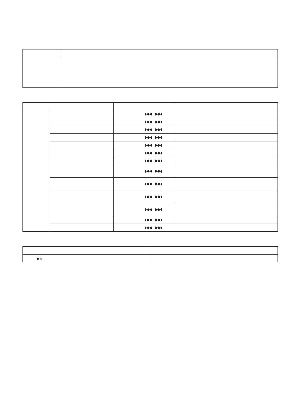
Test mode specifi cations in CD source
■
Display mode default: P-Time
• Procedure in CD-DA media (KTD-02A)
Key Display Description
Every time pressed, jumps to the track shown below.
No.9 → No.15 → No.10 → No.11 → No.12 → No.13 → No.22
Track up procedure
Track down procedure Goes down by 1 track from the currently played track.
Jump operation and
FAV
Mechanism version
display
TI/AUTO Jump operation
Jump operation and Mechanism version
display (Sub-mode)
Jump operation
* Toggling of jumping between tracks No. 9
and No. 22 (No.9 ↔ No.22)
No.14 → No.9 (recursive)
→
But in case the disc has 8 tracks or less, playback starts with
track No.1. (For both CD-DA and compressed fi le discs)
* Refer to “Jump operation and Mechanism version display” for
contents and operation of the display.
Jump to No. 9 when the track of No. 22 is being played back.
Jump to No. 22 when the track of No. 9 is being played back.
• Jump operation and Mechanism version display (Sub-mode)
* When operating the jump operation of the track while the mechanism information in this sub-mode, the track number is dis-
played for the specifi c period of time (prior to any other information) and then the mechanism information is displayed again.
Key Display Description
FM
Jump operation
AM
Jump operation
Information display
Mechanism μ-com
version
Information display
FAV
Mechanism servo
version
Information display
Mechanism boot
program version
TI/AUTO Jump operation
This operation is operational only in the “Jump
operation and Mechanism version display” during
CD source.
This operation is operational only in the “Jump
operation and Mechanism version display” during
CD source.
9B30:
SERV:
BOOT:
This operation is operational only in the “Jump
operation and Mechanism version display” during
CD source.
Jump to No. 28. (Scratch 0.7mm for MUSIC line vibration
testing)
Jump to No. 14. (Disc whose surface is not perfectly fl at:
TCD-731RA Tr14)
Display of Mechanism model name and Mechanism ver-
sion (Pressing the key while the indication in the left cell
is shown is to change to the mechanism servo version
display.)
Mechanism servo table version display (Pressing the key
while the indication in the left cell is shown is to change
to the mechanism boot program version display.)
Mechanism boot program version display (Pressing the
key while the indication in the left cell is shown is to
change to the normal display.)
Jump to No.15.
Set the volume value to 25. (For 20Hz 0dB DC protection
error operation FCT checking)
• Operations with the compressed media
Key Display
File format display (MP3)
File format display (WMA)
File format display (AAC)
MP 3
WM A
AAC
Description
Display fi le format just before the start of fi le play
back.
15
KDC-MP442U/MP6043U
/W5544U/W5644UY/X493
TEST MODE
Audio-related test mode
■
Procedure Note
Enter the audio adjustment mode.
When DUAL ZONE is ON: DUAL ZONE→FADER→BALANCE→BASS→MID→TRE→R-VOLUME→B.BOOST
TI/AUTO
■
About audio adjustment items (include both Audio Function Mode and Audio Setup Mode)
Procedure Item Procedure Description
For item
forwarding
procedure,
press [AUD]
key and
[FM] key
USER→HPF-F→HPF-R→V-OFFSET
When DUAL ZONE is OFF: DUAL ZONE→FADER→BALANCE→BASS→MID→TRE→SUB-W→B.BOOST
USER→HPF-F→HPF-R→LPF-SW→V-OFFSET
Dual Zone [VOL] knob and [
Fader [VOL] knob and [
Balance [VOL] knob and [
R-VOLUME [VOL] knob and [
Bass Level [VOL] knob and [
Middle Level [VOL] knob and [
Treble Level [VOL] knob and [
HPF Front [VOL] knob and [
HPF Rear [VOL] knob and [
LPF Subwoofer [VOL] knob and [
LPF Subwoofer Phase [VOL] knob and [
Volume Offset [VOL] knob and [
Bass BOOST [VOL] knob and [
/ ] key Adjust to 2 steps of OFF ↔ ON. (Default value: OFF)
/ ] key Adjust to 3 steps of R15 ↔ 0 ↔ F15. (Default value: 0)
/ ] key Adjust to 3 steps of L15 ↔ 0 ↔ R15. (Default value: 0)
/ ] key Adjust to 2 steps of 0 ↔ 35. (Default value: 35)
/ ] key Adjust to 3 steps of -8 ↔ 0 ↔ +8. (Default value 0)
/ ] key Adjust to 3 steps of -8 ↔ 0 ↔ +8. (Default value 0)
/ ] key Adjust to 3 steps of -8 ↔ 0 ↔ +8. (Default value 0)
/ ] key
/ ] key
/ ] key
/ ] key
/ ] key Adjust to 2 steps of -8 ↔ 0. (Default value 0)
/ ] key Adjust to 2 steps of OFF ↔ ON. (Default value OFF)
Adjust to 2 steps of Through ↔ 180Hz.
(Default value: Through)
Adjust to 2 steps of Through ↔ 180Hz.
(Default value: Through)
Adjust to 2 steps of 60Hz ↔ Through.
(Default value: Through)
Adjust to 2 steps of Normal ↔ Reverse.
(Default value: Normal)
→
→
[ATT] key operation
■
Press [
] key briefl y in the Tuner source. ATT OFF/ON
16
Procedure Note
 Loading...